Embed Size (px)
Citation preview

Document for
mini SCADA
design and
development
NOTE: It is published in connection with application to be
filled for the Intellectual Property Right (IPR) for the above
project. If any person having objection regarding the above
project, please write to us at [email protected]
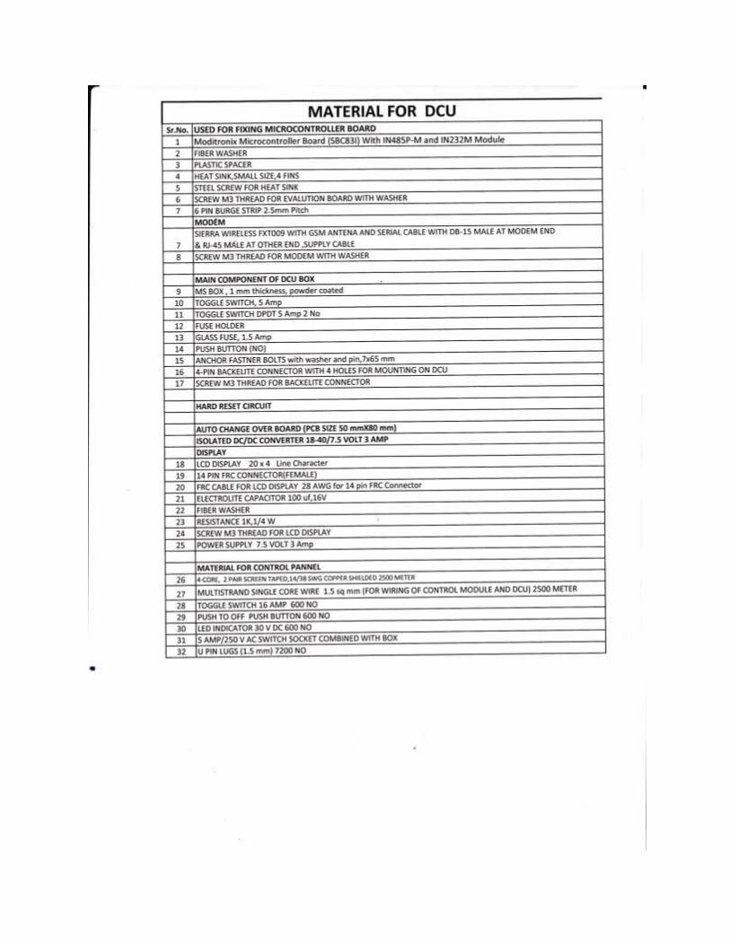
Data Concentrator Unit (DCU)
DCU module consists of -
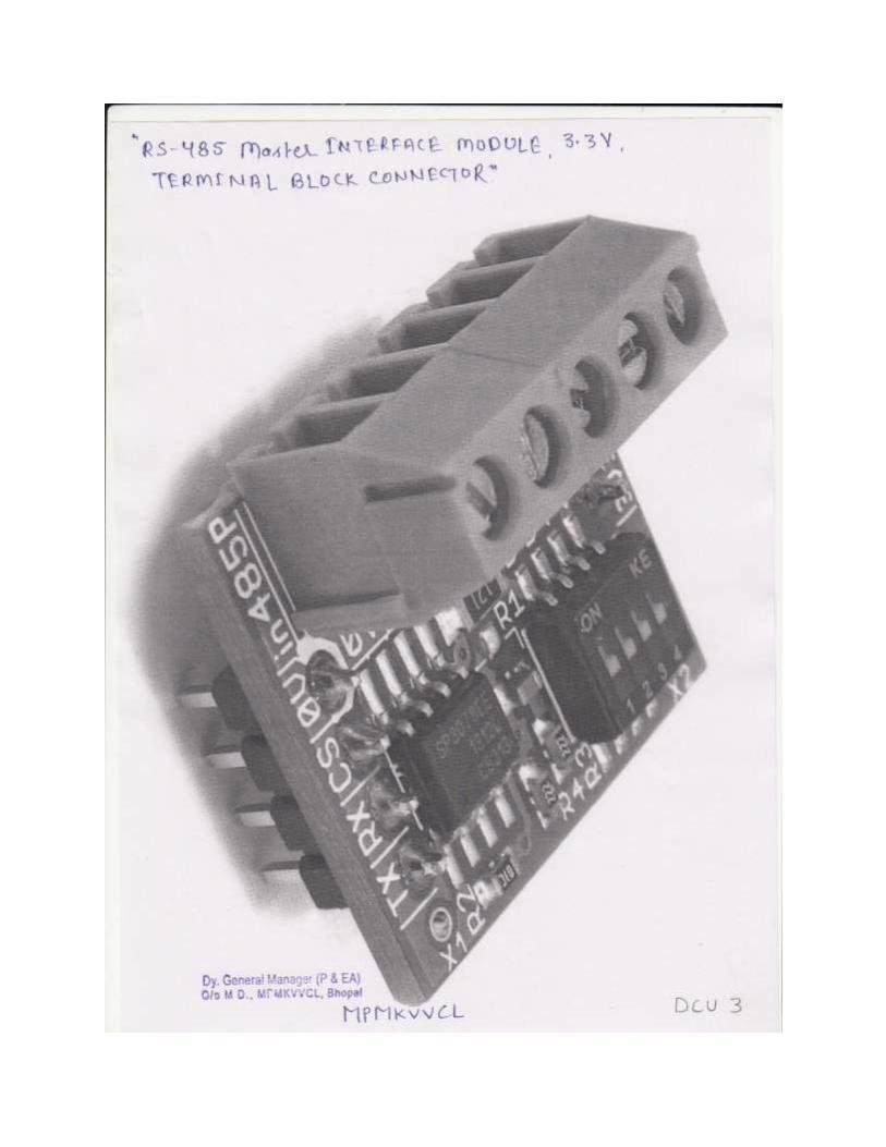
1) Evolution board of Modtronix make and model no. SBC83I R2 with IN 485 P –
M and IN 232M module.
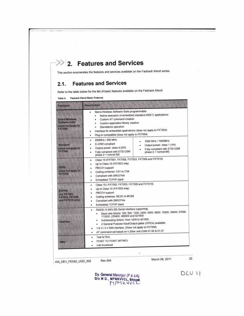
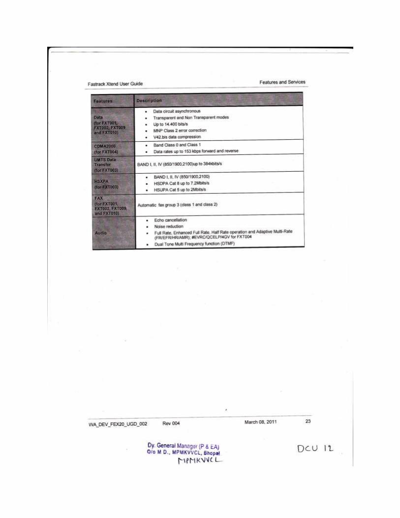
2) Modem of make Sierra Wireless(FASTRACK XTEND) and model no. FXT009.
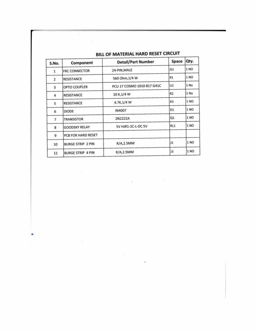
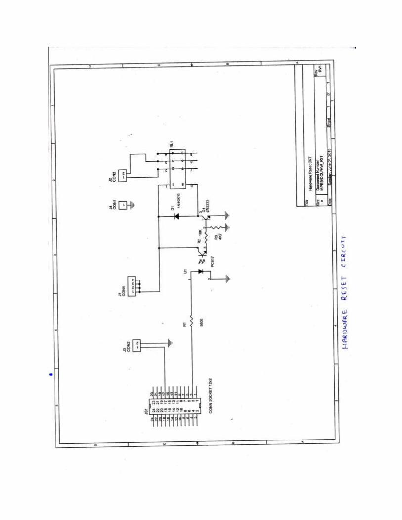
3) Hard Reset Circuit.
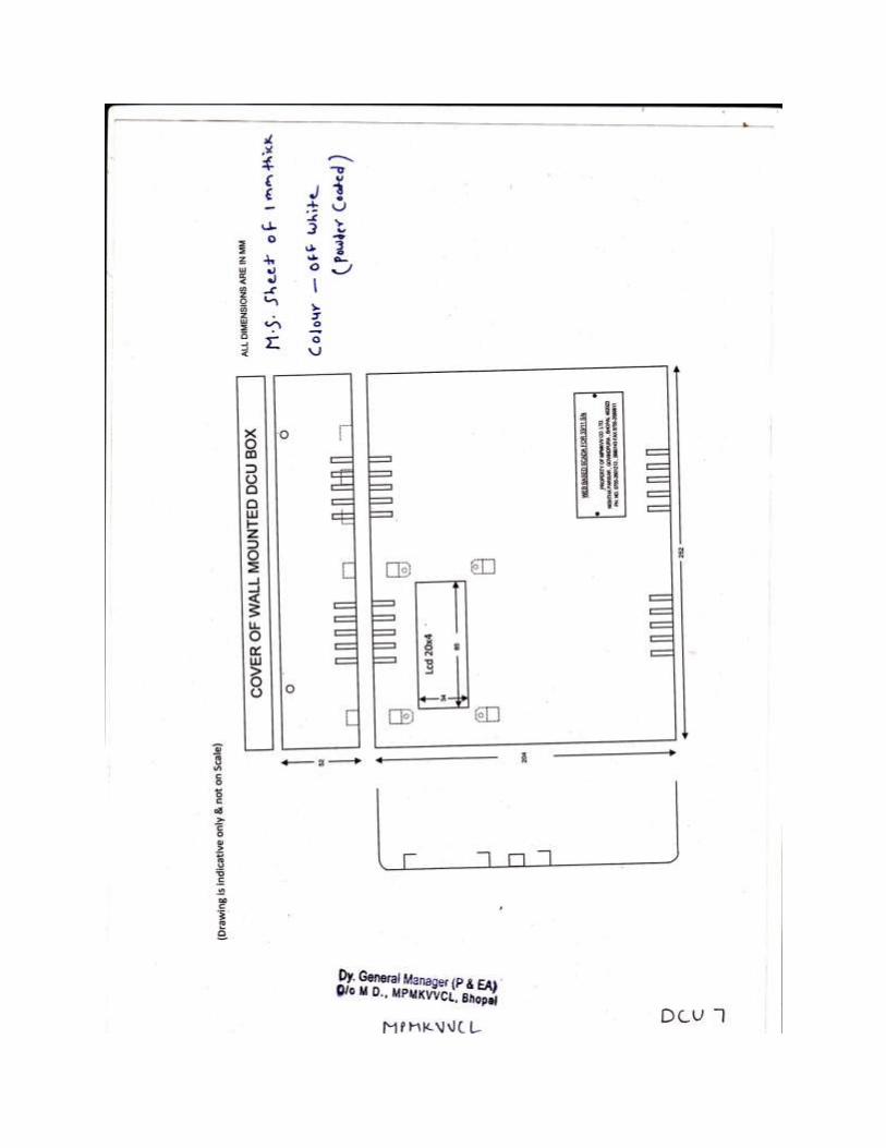
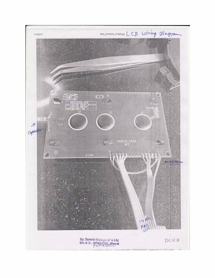
4) LCD display 20X4 character.
5) SMPS 7.5 Volt 3 amp. DC
6) Auto Change Over Board (PCB Size 50 mmX80 mm)
7) Isolated DC/DC Converter 18-40/7.5 Volt 3 Amp
8) Dual Band 900/1800 MHZ 3 dBi Omni directional magnetic mount antenna GSM
cellular aerial with 3 meter cable with SMA male connector.
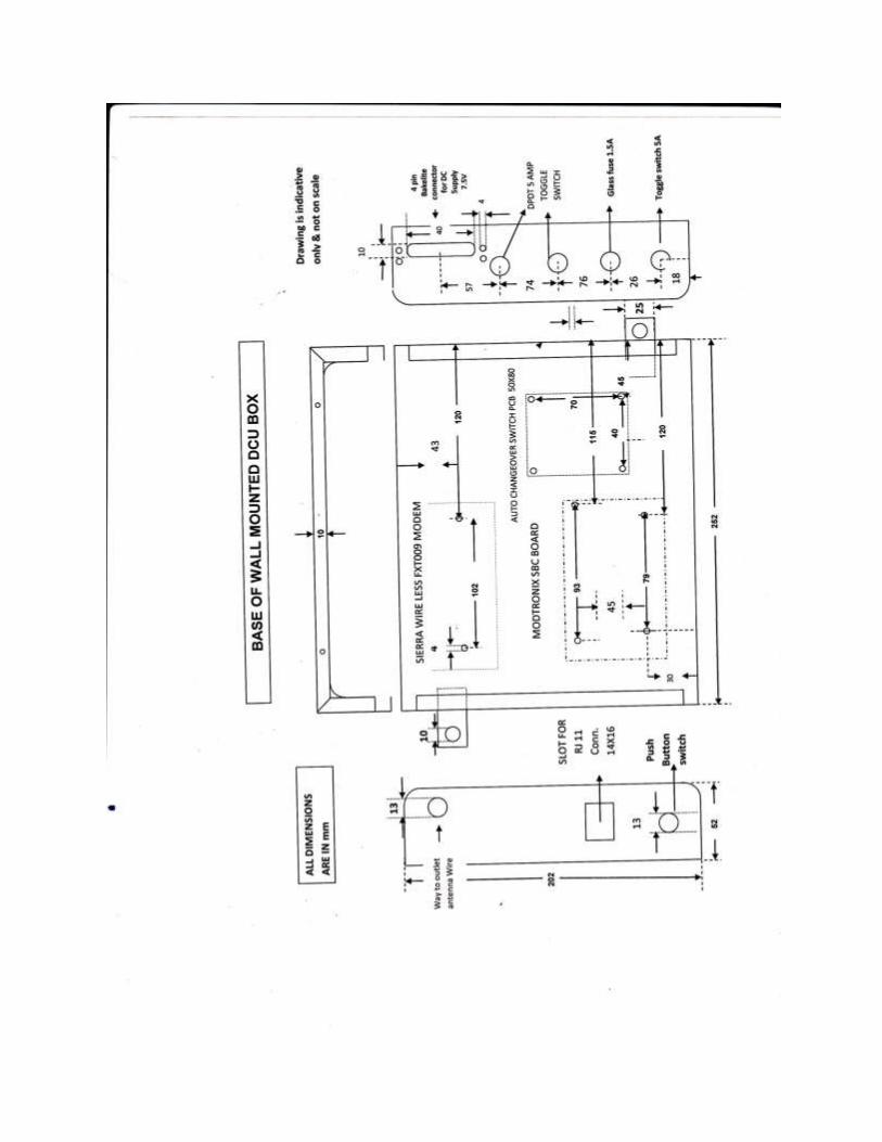
Power supply to the DCU box is given through SMPS/DCDC converter of 7.5 volt DC, 3
ampere. The output of SMPS and DC/DC converter connected to DCU Box through 4 pin
Bakelite connector. The SMPS and DC/DC converter should be branded make and mounted on
suitable single wall mounted casing. Inside the DCU box one of the supply is selected through
autochange over board and feed to the DC jack of Evolution Board through 2 ampere toggle
switch and glass fuse of 1.5 ampere and to Modem through hard reset board. The supply is
extended from evolution board (through Berge strip) to hard reset circuit (5 volt).It is also
connected to modem through hard reset circuit. Then supply from hard reset circuit given to
LCD. The connection diagram is given in drawing for reference. Two no module IM232M and
IN485P-M shall be fitted to evolution board. All above module shall be fitted in the MS steel
Box. The top cover of the DCU box should be hinged with base part. Passive components like
resistor, capacitor etc. shall only be procured from AVX or/and Kemet or/and Vishay or/and
Epcos. All the active components should be exactly as per bill of material.
The display unit is connected from evolution board through 14 cores FRC (28 AWG) and
connector. Display unit shall be fitted in the Top cover of DCU box.
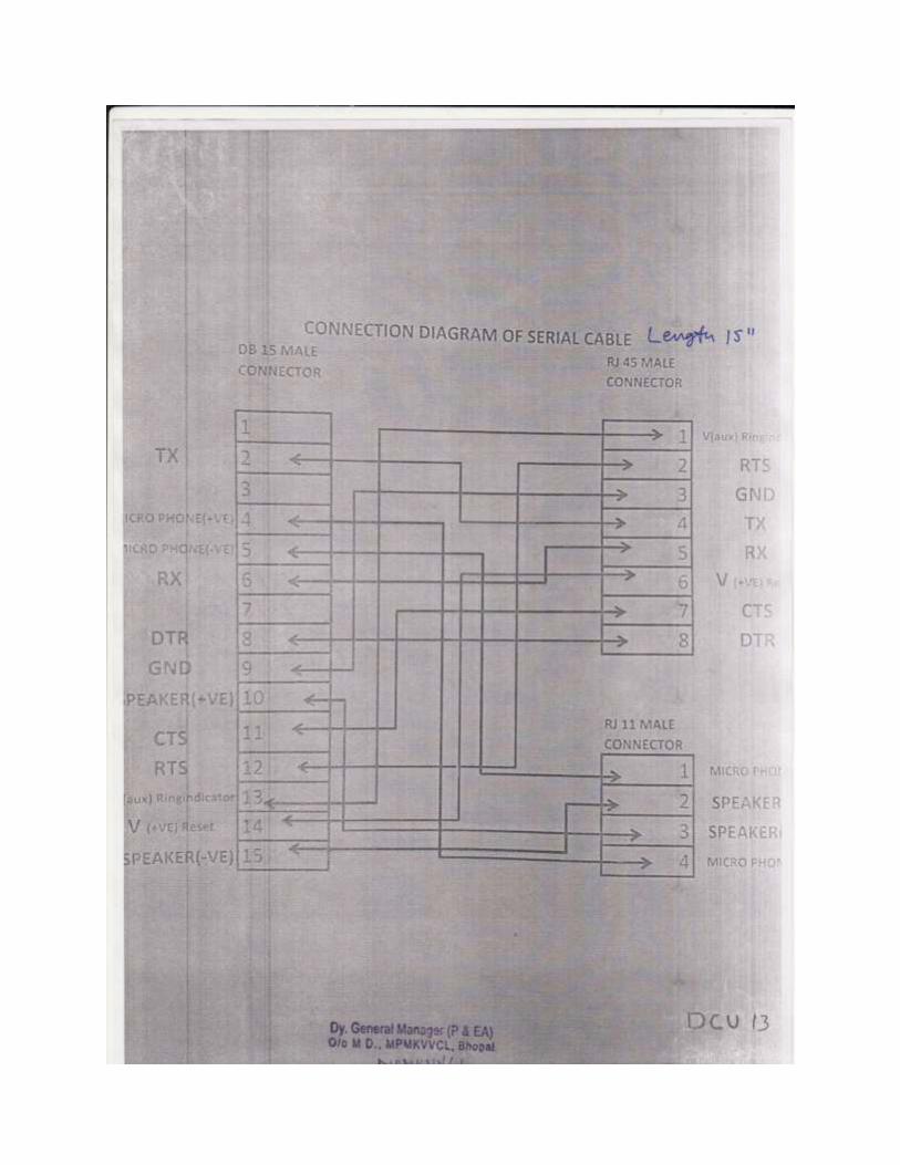
The data input cable to modem will be connected through D-15 connector to modem and through
IM232M to evolution board.
1 no. heat sink (4 fins) is to be mounted on voltage regulator IC (5 volt).
The drawings and bill of material is attached hereafter.


Breaker Control Module
The PCB of Breaker Control Module shall be placed in enclosure of make Universal DIN Rail
Enclosure UE – 105. Suitable connectors shall be fitted on both the end of PCB as per the
drawing enclosed. The drawings and bill of material is attached hereafter.


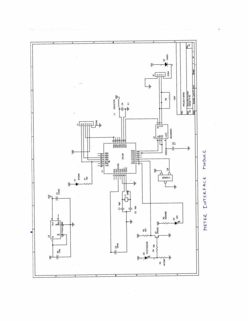
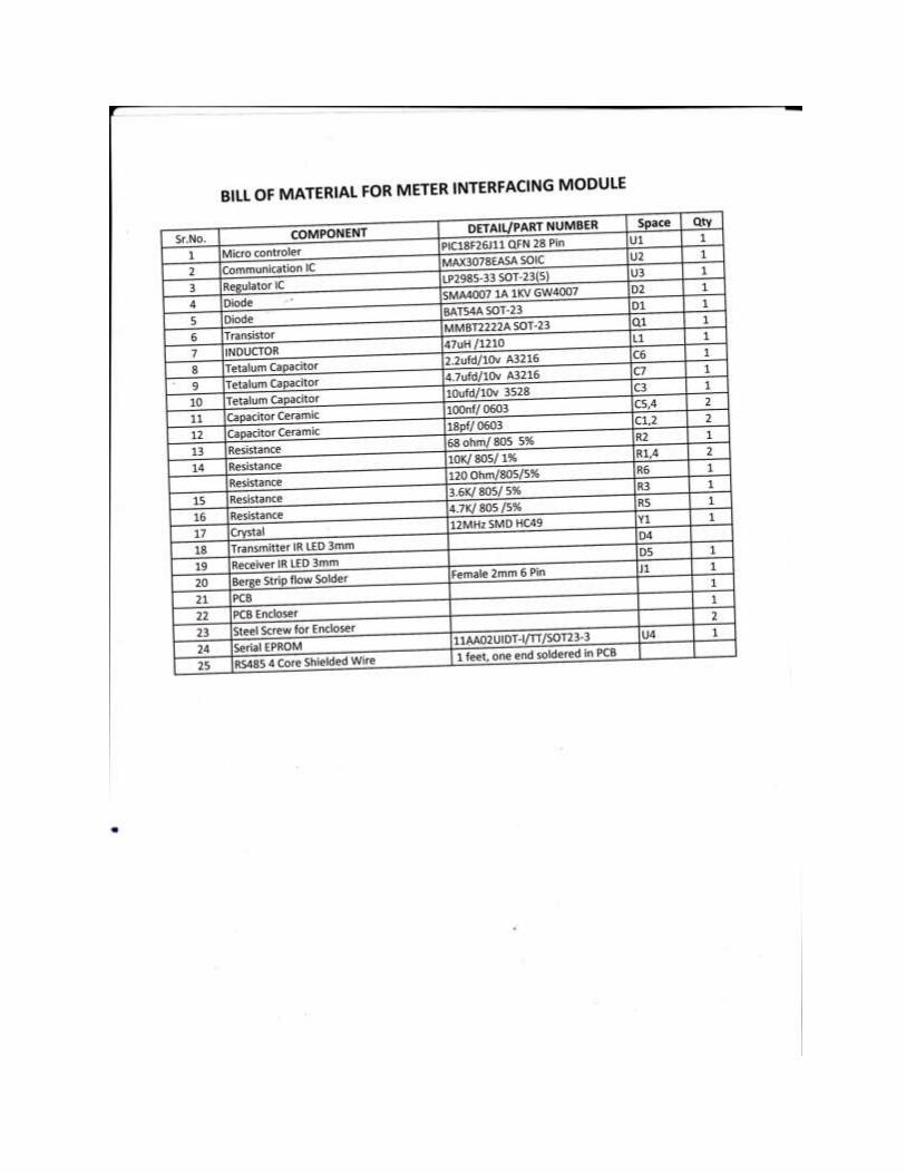
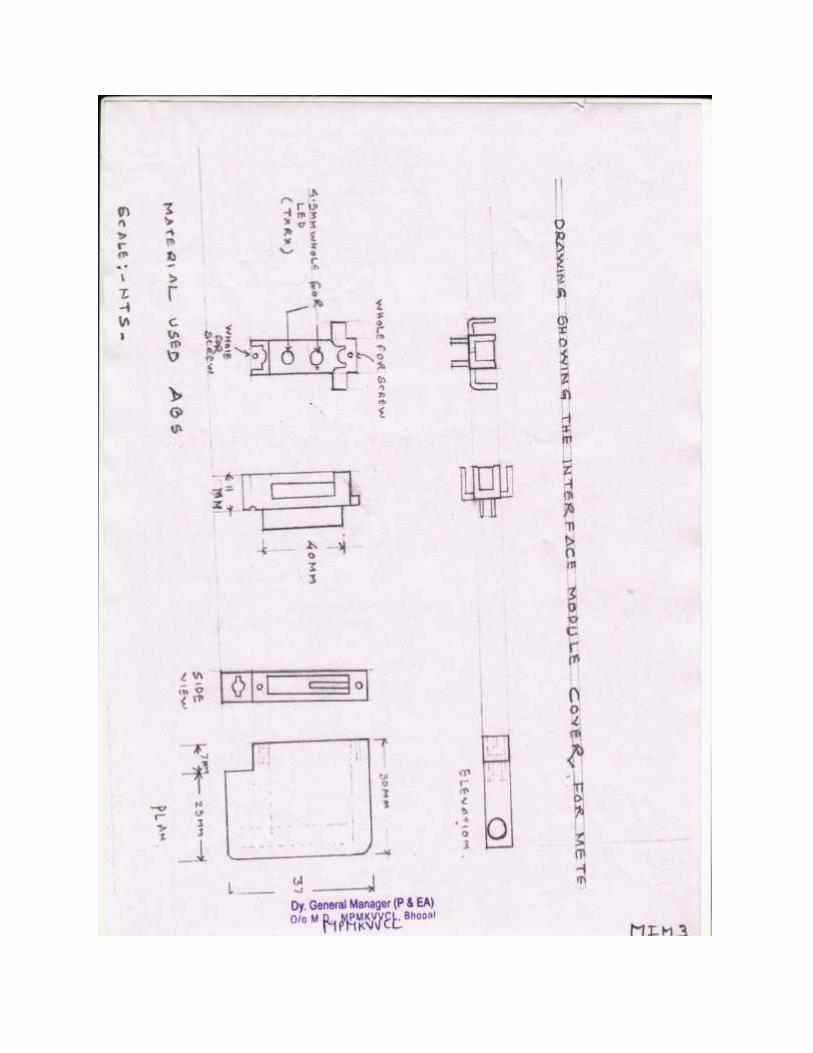
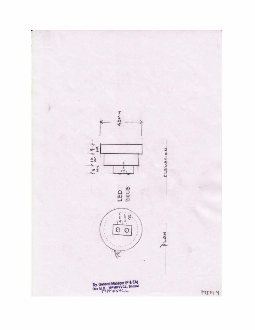
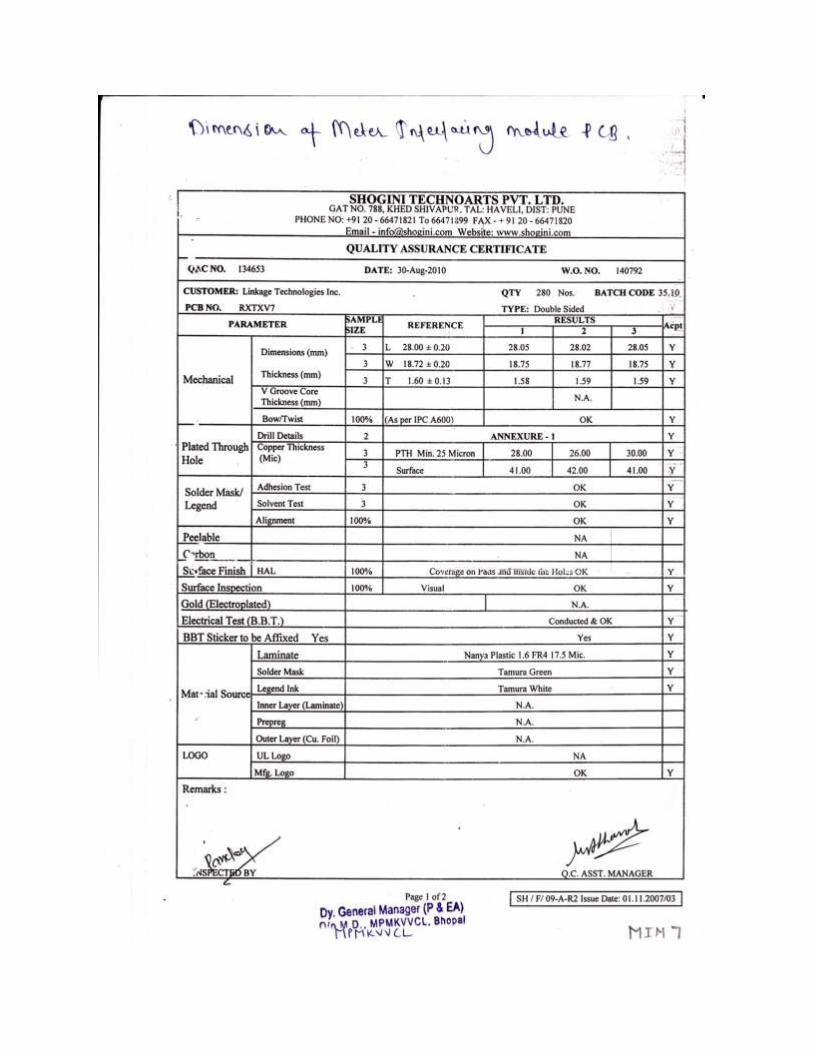
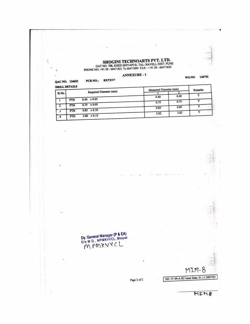
Meter Interface Module
Meter interface module shall be fitted in the enclosure as per drawing attached. 18
inches long 4 core 2 pair screen taped 14/38 SWG copper shielded wire shall be
soldered in the output of module.(in 4 pin connector) as per the drawing attached.
The enclosure shall be in rectangle and round shape. The drawings and bill of
material is given hereafter. The round shape enclosure should be compatible to all
type of meters as per their fixing arrangment.


![ฟังก์ชัÉนSCADA มาตรฐานfile.siam2web.com/bangprakong/files[document]/20141016_36946.pdf · ฟังก์ชัÉนscada](https://img.pdfslide.net/doc/110x75/5aa2c28a7f8b9a1f6d8dae8b/scada-file-document2014101636946pdfscada.jpg)