Embed Size (px)
Citation preview

Elevations Drawings
DoorKing Model 1602
Parking Barrier Arm
1602 - Top View
1602 - Side View
1602 - Front View
Layout 1
DoorKing Model 1602
Parking Barrier Arm
w/27' Arm Kit
w/One-Way Entrance or Exit Drive
w/DoorKing Card Reader/Keypad
w/Right-hand Operator Mount
w/6' Loops for High Vehicles
Layout 2
DoorKing Model 1602
Parking Barrier Arm
w/27' Arm Kit
w/One-Way Entrance or Exit Drive
w/DoorKing Card Reader/Keypad
w/Left-hand Operator Mount
w/6' Loops for High Vehicles
Layout 3
DoorKing Model 1602
Parking Barrier Arm
w/27' Arm Kit
w/One-Way Exit Drive
w/Right-hand Operator Mount
w/6' Loops for High Vehicles
Layout 4
DoorKing Model 1602
Parking Barrier Arm
w/27' Arm Kit
w/One-Way Exit Drive
w/Left-hand Operator Mount
w/6' Loops for High Vehicles
Layout 5
DoorKing Model 1602
Parking Barrier Arm
w/27' Arm Kit
w/Two-Way Traffic
w/DoorKing Card Reader/Keypad Entry
w/DoorKing Card Reader/Keypad Exit
w/Right-hand Operator Mount
w/6' Loops for High Vehicles
Layout 6
DoorKing Model 1602
Parking Barrier Arm
w/27' Arm Kit
w/Two-Way Traffic
w/DoorKing Card Reader/Keypad Entry
w/DoorKing Card Reader/Keypad Exit
w/Left-hand Operator Mount
w/6' Loops for High Vehicles
Layout 7
DoorKing Model 1602
Parking Barrier Arm
w/27' Arm Kit
w/Two-Way Traffic
w/DoorKing Card Reader/Keypad Entry
w/Free Exit
w/Right-hand Operator Mount
w/6' Loops for High Vehicles
Layout 8
DoorKing Model 1602
Parking Barrier Arm
w/27' Arm Kit
w/Two-Way Traffic
w/DoorKing Card Reader/Keypad Entry
w/Free Exit
w/Left-hand Operator Mount
w/6' Loops for High Vehicles
Layout 9
DoorKing Model 1602
Parking Barrier Arm
w/27' Arm Kit
w/One-Way Entrance or Exit Drive
w/DoorKing Card Reader/Keypad
w/Bi-parting Operator Mount
w/6' Loops for High Vehicles
Layout 10
DoorKing Model 1602
Parking Barrier Arm
w/27' Arm Kit
w/One-Way Exit Drive
w/Bi-parting Operator Mount
w/6' Loops for High Vehicles
Layout 11
DoorKing Model 1602
Parking Barrier Arm
w/27' Arm Kit
w/Two-Way Traffic
w/DoorKing Card Reader/Keypad Entry
w/DoorKing Card Reader/Keypad Exit
w/Bi-parting Operator Mount
w/6' Loops for High Vehicles
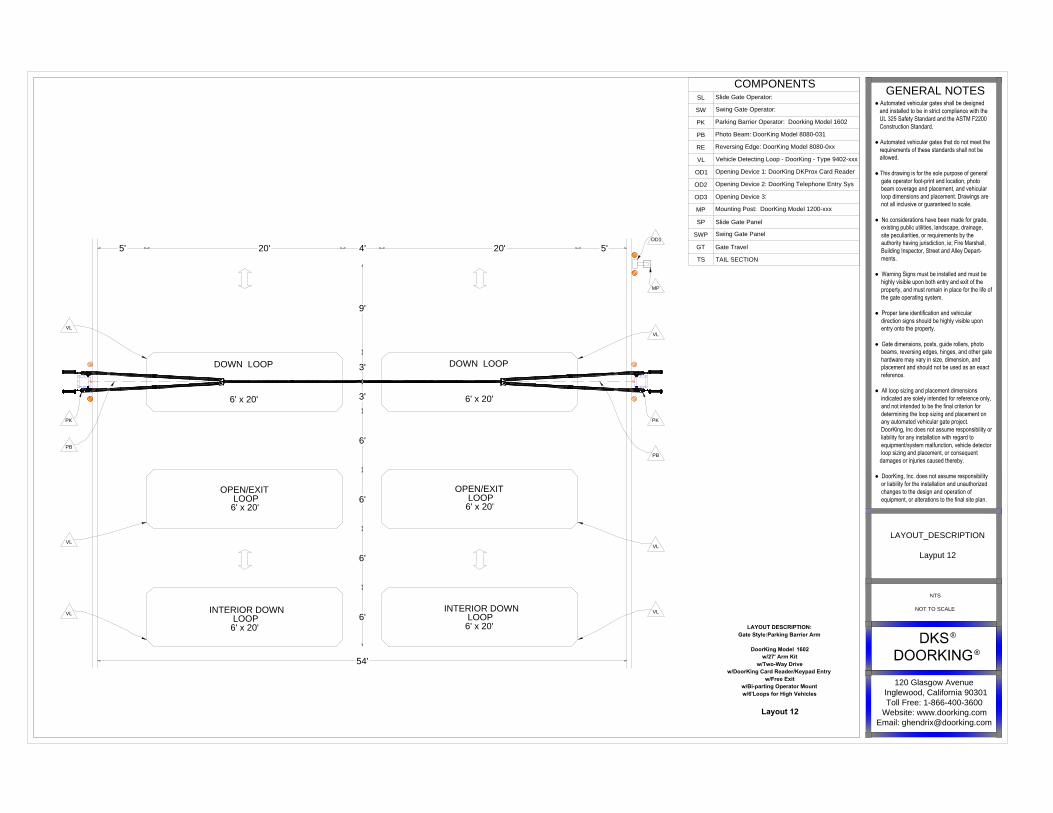
Layout 12
DoorKing Model 1602
Parking Barrier Arm
w/27' Arm Kit
w/Two-Way Drive
w/DoorKing Card Reader/Keypad Entry
w/Free Exit
w/Bi-parting Operator Mount
w/6' Loops for High Vehicles
Layout 13
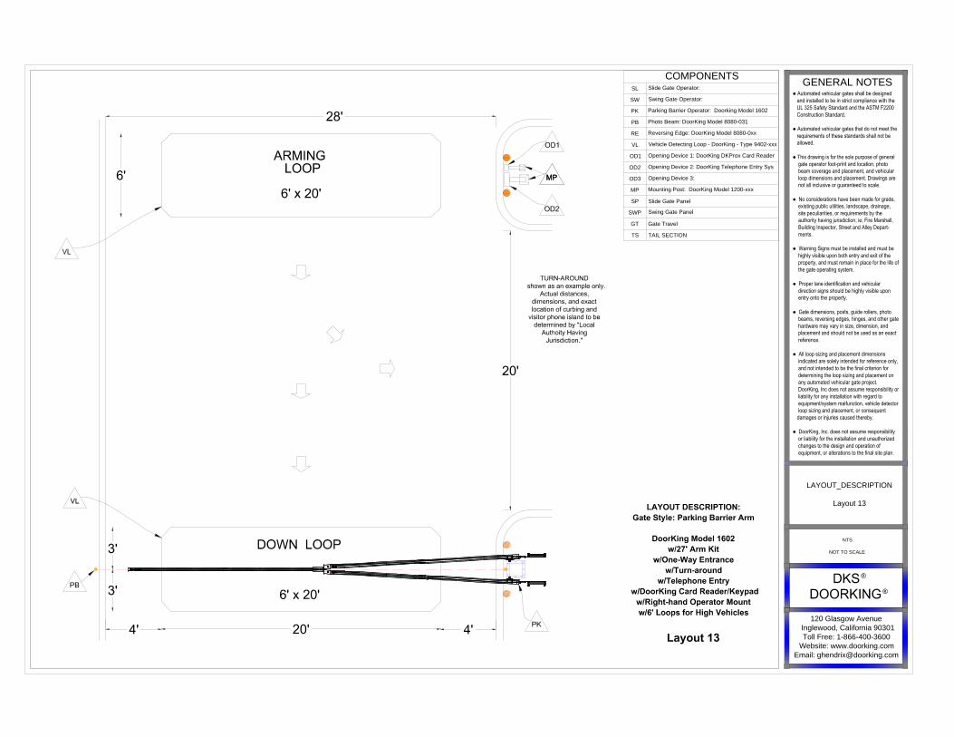
DoorKing Model 1602
Parking Barrier Arm
w/27' Arm Kit
w/One-Way Entrance
w/Turn-around
w/Telephone Entry
w/DoorKing Card Reader/Keypad
w/Right-hand Operator Mount
w/6' Loops for High Vehicles
Layout 14
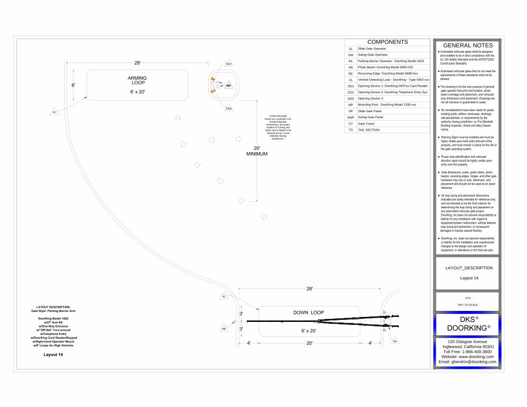
DoorKing Model 1602
Parking Barrier Arm
w/27' Arm Kit
w/One-Way Entrance
w/"Off-Set" Turn-around
w/Telephone Entry
w/DoorKing Card Reader/Keypad
w/Right-hand Operator Mount
w/6' Loops for High Vehicles
Layout 4
DoorKing Model 1602
Parking Barrier Arm
w/27' Arm Kit
w/One-Way Exit Drive
w/Left-hand Operator Mount
w/6' Loops for High Vehicles
Layout 5
DoorKing Model 1602
Parking Barrier Arm
w/27' Arm Kit
w/Two-Way Traffic
w/DoorKing Card Reader/Keypad Entry
w/DoorKing Card Reader/Keypad Exit
w/Right-hand Operator Mount
w/6' Loops for High Vehicles
Layout 6
DoorKing Model 1602
Parking Barrier Arm
w/27' Arm Kit
w/Two-Way Traffic
w/DoorKing Card Reader/Keypad Entry
w/DoorKing Card Reader/Keypad Exit
w/Left-hand Operator Mount
w/6' Loops for High Vehicles
Layout 7
DoorKing Model 1602
Parking Barrier Arm
w/27' Arm Kit
w/Two-Way Traffic
w/DoorKing Card Reader/Keypad Entry
w/Free Exit
w/Right-hand Operator Mount
w/6' Loops for High Vehicles
Layout 12
DoorKing Model 1602
Parking Barrier Arm
w/27' Arm Kit
w/Two-Way Drive
w/DoorKing Card Reader/Keypad Entry
w/Free Exit
w/Bi-parting Operator Mount
w/6' Loops for High Vehicles
Layout 13
DoorKing Model 1602
Parking Barrier Arm
w/27' Arm Kit
w/One-Way Entrance
w/Turn-around
w/Telephone Entry
w/DoorKing Card Reader/Keypad
w/Right-hand Operator Mount
w/6' Loops for High Vehicles
Layout 14
DoorKing Model 1602
Parking Barrier Arm
w/27' Arm Kit
w/One-Way Entrance
w/"Off-Set" Turn-around
w/Telephone Entry
w/DoorKing Card Reader/Keypad
w/Right-hand Operator Mount
w/6' Loops for High Vehicles
Layout 4
DoorKing Model 1602
Parking Barrier Arm
w/27' Arm Kit
w/One-Way Exit Drive
w/Left-hand Operator Mount
w/6' Loops for High Vehicles
Layout 5
DoorKing Model 1602
Parking Barrier Arm
w/27' Arm Kit
w/Two-Way Traffic
w/DoorKing Card Reader/Keypad Entry
w/DoorKing Card Reader/Keypad Exit
w/Right-hand Operator Mount
w/6' Loops for High Vehicles
Layout 6
DoorKing Model 1602
Parking Barrier Arm
w/27' Arm Kit
w/Two-Way Traffic
w/DoorKing Card Reader/Keypad Entry
w/DoorKing Card Reader/Keypad Exit
w/Left-hand Operator Mount
w/6' Loops for High Vehicles
Layout 7
DoorKing Model 1602
Parking Barrier Arm
w/27' Arm Kit
w/Two-Way Traffic
w/DoorKing Card Reader/Keypad Entry
w/Free Exit
w/Right-hand Operator Mount
w/6' Loops for High Vehicles
Layout 8
DoorKing Model 1602
Parking Barrier Arm
w/27' Arm Kit
w/Two-Way Traffic
w/DoorKing Card Reader/Keypad Entry
w/Free Exit
w/Left-hand Operator Mount
w/6' Loops for High Vehicles
Layout 9
DoorKing Model 1602
Parking Barrier Arm
w/27' Arm Kit
w/One-Way Entrance or Exit Drive
w/DoorKing Card Reader/Keypad
w/Bi-parting Operator Mount
w/6' Loops for High Vehicles
Layout 10
DoorKing Model 1602
Parking Barrier Arm
w/27' Arm Kit
w/One-Way Exit Drive
w/Bi-parting Operator Mount
w/6' Loops for High Vehicles
Layout 11
DoorKing Model 1602
Parking Barrier Arm
w/27' Arm Kit
w/Two-Way Traffic
w/DoorKing Card Reader/Keypad Entry
w/DoorKing Card Reader/Keypad Exit
w/Bi-parting Operator Mount
w/6' Loops for High Vehicles
Layout 12
DoorKing Model 1602
Parking Barrier Arm
w/27' Arm Kit
w/Two-Way Drive
w/DoorKing Card Reader/Keypad Entry
w/Free Exit
w/Bi-parting Operator Mount
w/6' Loops for High Vehicles
Layout 13
DoorKing Model 1602
Parking Barrier Arm
w/27' Arm Kit
w/One-Way Entrance
w/Turn-around
w/Telephone Entry
w/DoorKing Card Reader/Keypad
w/Right-hand Operator Mount
w/6' Loops for High Vehicles
Layout 14
DoorKing Model 1602
Parking Barrier Arm
w/27' Arm Kit
w/One-Way Entrance
w/"Off-Set" Turn-around
w/Telephone Entry
w/DoorKing Card Reader/Keypad
w/Right-hand Operator Mount
w/6' Loops for High Vehicles
DOCUMENT HISTORY
DATE OF ORIGIN/RELEASE 05/22/2015
REV DESCRIPTION OF REVISION DATE
120 Glasgow Avenue
Inglewood, California 90301
Toll Free: 1-866-400-3600
Website: www.doorking.com
Email: [email protected]
GENERAL NOTES
● Automated vehicular gates shall be designed and installed to be in strict compliance with the UL 325 Safety Standard and the ASTM F2200 Construction Standard.
● Automated vehicular gates that do not meet the requirements of these standards shall not be allowed.
● This drawing is for the sole purpose of general gate operator foot-print and location, photo beam coverage and placement, and vehicular loop dimensions and placement. Drawings are not all inclusive or guaranteed to scale.
● No considerations have been made for grade, existing public utilities, landscape, drainage, site peculiarities, or requirements by the authority having jurisdiction, ie; Fire Marshall, Building Inspector, Street and Alley Depart- ments.
● Warning Signs must be installed and must be highly visible upon both entry and exit of the property, and must remain in place for the life of the gate operating system.
● Proper lane identification and vehicular direction signs should be highly visible upon entry onto the property.
● Gate dimensions, posts, guide rollers, photo beams, reversing edges, hinges, and other gate hardware may vary in size, dimension, and placement and should not be used as an exact reference.
● All loop sizing and placement dimensions indicated are solely intended for reference only, and not intended to be the final criterion for determining the loop sizing and placement on any automated vehicular gate project. DoorKing, Inc does not assume responsibility or liability for any installation with regard to equipment/system malfunction, vehicle detector loop sizing and placement, or consequent damages or injuries caused thereby.
● DoorKing, Inc. does not assume responsibility or liability for the installation and unauthorized changes to the design and operation of equipment, or alterations to the final site plan.
NTS
NOT TO SCALE
CONTENTS
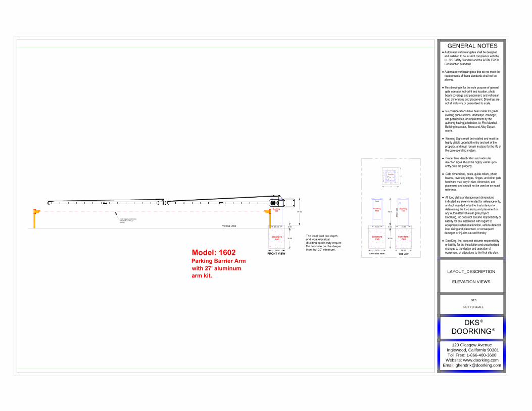
Model: 1602
Parking Barrier Arm
with 27' aluminum
arm kit.
DOOR-SIDE VIEW
SIDE VIEW
24.00
CONCRETE
PAD
CONCRETE
PAD
4.00
30.00
24.00
Door
ST
RE
ET
S
ID
E
11.50
Conduit Area
39.61
15.5015.00
24.00
11.00
15.50
15.00
24.00
DoorKing
1602
DoorKing
1602
VEHICLE LANE
PHOTO-BEAM LOCATION
MAXIMUM 27" FROM
GRADE
FRONT VIEW
CONCRETE
PAD
24.00
4.00
30.00
15.50
39.61
DoorKing
1602
120 Glasgow Avenue
Inglewood, California 90301
Toll Free: 1-866-400-3600
Website: www.doorking.com
Email: [email protected]
GENERAL NOTES
● Automated vehicular gates shall be designed and installed to be in strict compliance with the UL 325 Safety Standard and the ASTM F2200 Construction Standard.
● Automated vehicular gates that do not meet the requirements of these standards shall not be allowed.
● This drawing is for the sole purpose of general gate operator foot-print and location, photo beam coverage and placement, and vehicular loop dimensions and placement. Drawings are not all inclusive or guaranteed to scale.
● No considerations have been made for grade, existing public utilities, landscape, drainage, site peculiarities, or requirements by the authority having jurisdiction, ie; Fire Marshall, Building Inspector, Street and Alley Depart- ments.
● Warning Signs must be installed and must be highly visible upon both entry and exit of the property, and must remain in place for the life of the gate operating system.
● Proper lane identification and vehicular direction signs should be highly visible upon entry onto the property.
● Gate dimensions, posts, guide rollers, photo beams, reversing edges, hinges, and other gate hardware may vary in size, dimension, and placement and should not be used as an exact reference.
● All loop sizing and placement dimensions indicated are solely intended for reference only, and not intended to be the final criterion for determining the loop sizing and placement on any automated vehicular gate project. DoorKing, Inc does not assume responsibility or liability for any installation with regard to equipment/system malfunction, vehicle detector loop sizing and placement, or consequent damages or injuries caused thereby.
● DoorKing, Inc. does not assume responsibility or liability for the installation and unauthorized changes to the design and operation of equipment, or alterations to the final site plan.
NTS
NOT TO SCALE
LAYOUT_DESCRIPTION
ELEVATION VIEWS

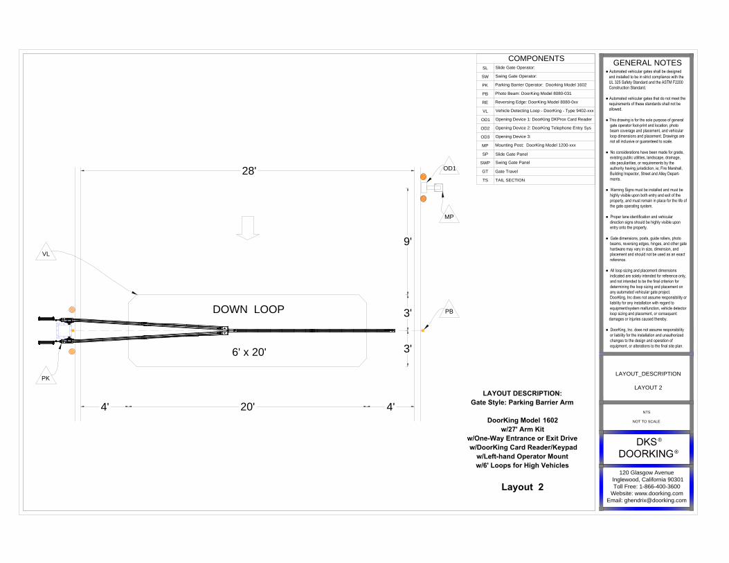
LAYOUT DESCRIPTION:
Gate Style: Parking Barrier Arm
DoorKing Model 1602
w/27' Arm Kit
w/One-Way Entr4ance or Exit Drive
w/DoorKing Card Reader/Keypad
w/Right-hand Operator Mount
w/6' Loops for High Vehicles
Layout 1
DOWN LOOP
6' x 20'
VL
OD1
MP
PK
20'4' 4'
3'
9'
3'
28'
PB
COMPONENTS
SL
Slide Gate Operator:
SW
Swing Gate Operator:
PK
Parking Barrier Operator: Doorking Model 1602
PB
Photo Beam: DoorKing Model 8080-031
RE
Reversing Edge: DoorKing Model 8080-0xx
VL
Vehicle Detecting Loop - DoorKing - Type 9402-xxx
OD1
Opening Device 1: DoorKing DKProx Card Reader
OD2
Opening Device 2: DoorKing Telephone Entry Sys
OD3
Opening Device 3:
MP
Mounting Post: DoorKing Model 1200-xxx
SP Slide Gate Panel
SWPSwing Gate Panel
GT Gate Travel
TS TAIL SECTION
120 Glasgow Avenue
Inglewood, California 90301
Toll Free: 1-866-400-3600
Website: www.doorking.com
Email: [email protected]
GENERAL NOTES
● Automated vehicular gates shall be designed and installed to be in strict compliance with the UL 325 Safety Standard and the ASTM F2200 Construction Standard.
● Automated vehicular gates that do not meet the requirements of these standards shall not be allowed.
● This drawing is for the sole purpose of general gate operator foot-print and location, photo beam coverage and placement, and vehicular loop dimensions and placement. Drawings are not all inclusive or guaranteed to scale.
● No considerations have been made for grade, existing public utilities, landscape, drainage, site peculiarities, or requirements by the authority having jurisdiction, ie; Fire Marshall, Building Inspector, Street and Alley Depart- ments.
● Warning Signs must be installed and must be highly visible upon both entry and exit of the property, and must remain in place for the life of the gate operating system.
● Proper lane identification and vehicular direction signs should be highly visible upon entry onto the property.
● Gate dimensions, posts, guide rollers, photo beams, reversing edges, hinges, and other gate hardware may vary in size, dimension, and placement and should not be used as an exact reference.
● All loop sizing and placement dimensions indicated are solely intended for reference only, and not intended to be the final criterion for determining the loop sizing and placement on any automated vehicular gate project. DoorKing, Inc does not assume responsibility or liability for any installation with regard to equipment/system malfunction, vehicle detector loop sizing and placement, or consequent damages or injuries caused thereby.
● DoorKing, Inc. does not assume responsibility or liability for the installation and unauthorized changes to the design and operation of equipment, or alterations to the final site plan.
LAYOUT_DESCRIPTION
LAYOUT 1
NTS
NOT TO SCALE
LAYOUT DESCRIPTION:
Gate Style: Parking Barrier Arm
DoorKing Model 1602
w/27' Arm Kit
w/One-Way Entrance or Exit Drive
w/DoorKing Card Reader/Keypad
w/Left-hand Operator Mount
w/6' Loops for High Vehicles
Layout 2
DOWN LOOP
6' x 20'
VL
OD1
MP
PK
20' 4'4'
3'
9'
3'
28'
PB
COMPONENTS
SL
Slide Gate Operator:
SW
Swing Gate Operator:
PK
Parking Barrier Operator: Doorking Model 1602
PB
Photo Beam: DoorKing Model 8080-031
RE
Reversing Edge: DoorKing Model 8080-0xx
VL
Vehicle Detecting Loop - DoorKing - Type 9402-xxx
OD1
Opening Device 1: DoorKing DKProx Card Reader
OD2
Opening Device 2: DoorKing Telephone Entry Sys
OD3
Opening Device 3:
MP
Mounting Post: DoorKing Model 1200-xxx
SP Slide Gate Panel
SWPSwing Gate Panel
GT Gate Travel
TS TAIL SECTION
120 Glasgow Avenue
Inglewood, California 90301
Toll Free: 1-866-400-3600
Website: www.doorking.com
Email: [email protected]
GENERAL NOTES
● Automated vehicular gates shall be designed and installed to be in strict compliance with the UL 325 Safety Standard and the ASTM F2200 Construction Standard.
● Automated vehicular gates that do not meet the requirements of these standards shall not be allowed.
● This drawing is for the sole purpose of general gate operator foot-print and location, photo beam coverage and placement, and vehicular loop dimensions and placement. Drawings are not all inclusive or guaranteed to scale.
● No considerations have been made for grade, existing public utilities, landscape, drainage, site peculiarities, or requirements by the authority having jurisdiction, ie; Fire Marshall, Building Inspector, Street and Alley Depart- ments.
● Warning Signs must be installed and must be highly visible upon both entry and exit of the property, and must remain in place for the life of the gate operating system.
● Proper lane identification and vehicular direction signs should be highly visible upon entry onto the property.
● Gate dimensions, posts, guide rollers, photo beams, reversing edges, hinges, and other gate hardware may vary in size, dimension, and placement and should not be used as an exact reference.
● All loop sizing and placement dimensions indicated are solely intended for reference only, and not intended to be the final criterion for determining the loop sizing and placement on any automated vehicular gate project. DoorKing, Inc does not assume responsibility or liability for any installation with regard to equipment/system malfunction, vehicle detector loop sizing and placement, or consequent damages or injuries caused thereby.
● DoorKing, Inc. does not assume responsibility or liability for the installation and unauthorized changes to the design and operation of equipment, or alterations to the final site plan.
LAYOUT_DESCRIPTION
LAYOUT 2
NTS
NOT TO SCALE
OPEN/EXIT
LOOP
6' x 20'
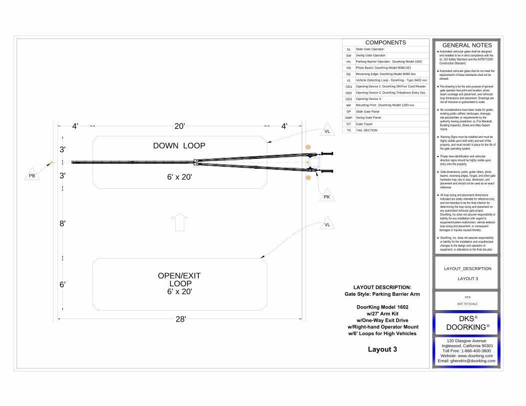
LAYOUT DESCRIPTION:
Gate Style: Parking Barrier Arm
DoorKing Model 1602
w/27' Arm Kit
w/One-Way Exit Drive
w/Right-hand Operator Mount
w/6' Loops for High Vehicles
Layout 3
DOWN LOOP
6' x 20'
VL
VL
PK
20'4' 4'
3'
6'
28'
3'
8'
PB
COMPONENTS
SL
Slide Gate Operator:
SW
Swing Gate Operator:
PK
Parking Barrier Operator: Doorking Model 1602
PB
Photo Beam: DoorKing Model 8080-031
RE
Reversing Edge: DoorKing Model 8080-0xx
VL
Vehicle Detecting Loop - DoorKing - Type 9402-xxx
OD1
Opening Device 1: DoorKing DKProx Card Reader
OD2
Opening Device 2: DoorKing Telephone Entry Sys
OD3
Opening Device 3:
MP
Mounting Post: DoorKing Model 1200-xxx
SP Slide Gate Panel
SWPSwing Gate Panel
GT Gate Travel
TS TAIL SECTION
120 Glasgow Avenue
Inglewood, California 90301
Toll Free: 1-866-400-3600
Website: www.doorking.com
Email: [email protected]
GENERAL NOTES
● Automated vehicular gates shall be designed and installed to be in strict compliance with the UL 325 Safety Standard and the ASTM F2200 Construction Standard.
● Automated vehicular gates that do not meet the requirements of these standards shall not be allowed.
● This drawing is for the sole purpose of general gate operator foot-print and location, photo beam coverage and placement, and vehicular loop dimensions and placement. Drawings are not all inclusive or guaranteed to scale.
● No considerations have been made for grade, existing public utilities, landscape, drainage, site peculiarities, or requirements by the authority having jurisdiction, ie; Fire Marshall, Building Inspector, Street and Alley Depart- ments.
● Warning Signs must be installed and must be highly visible upon both entry and exit of the property, and must remain in place for the life of the gate operating system.
● Proper lane identification and vehicular direction signs should be highly visible upon entry onto the property.
● Gate dimensions, posts, guide rollers, photo beams, reversing edges, hinges, and other gate hardware may vary in size, dimension, and placement and should not be used as an exact reference.
● All loop sizing and placement dimensions indicated are solely intended for reference only, and not intended to be the final criterion for determining the loop sizing and placement on any automated vehicular gate project. DoorKing, Inc does not assume responsibility or liability for any installation with regard to equipment/system malfunction, vehicle detector loop sizing and placement, or consequent damages or injuries caused thereby.
● DoorKing, Inc. does not assume responsibility or liability for the installation and unauthorized changes to the design and operation of equipment, or alterations to the final site plan.
LAYOUT_DESCRIPTION
LAYOUT 3
NTS
NOT TO SCALE
OPEN/EXIT
LOOP
6' x 20'
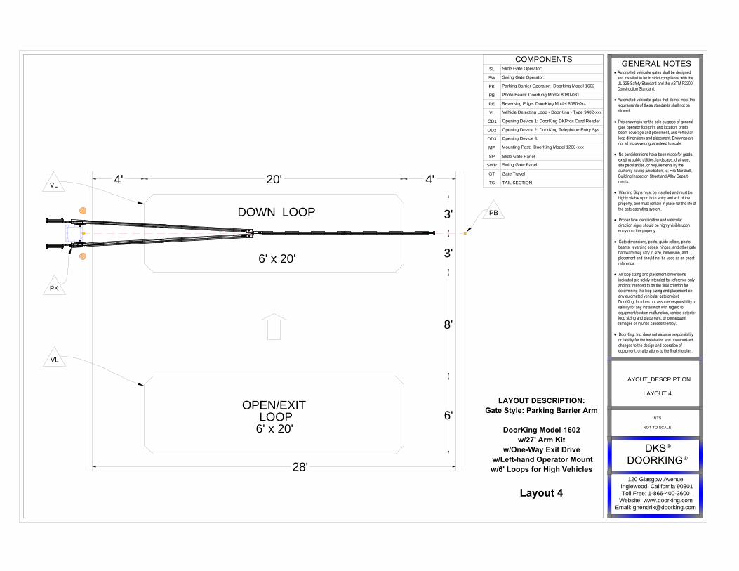
LAYOUT DESCRIPTION:
Gate Style: Parking Barrier Arm
DoorKing Model 1602
w/27' Arm Kit
w/One-Way Exit Drive
w/Left-hand Operator Mount
w/6' Loops for High Vehicles
Layout 4
DOWN LOOP
6' x 20'
VL
VL
PK
20' 4'4'
3'
6'
28'
3'
8'
PB
COMPONENTS
SL
Slide Gate Operator:
SW
Swing Gate Operator:
PK
Parking Barrier Operator: Doorking Model 1602
PB
Photo Beam: DoorKing Model 8080-031
RE
Reversing Edge: DoorKing Model 8080-0xx
VL
Vehicle Detecting Loop - DoorKing - Type 9402-xxx
OD1
Opening Device 1: DoorKing DKProx Card Reader
OD2
Opening Device 2: DoorKing Telephone Entry Sys
OD3
Opening Device 3:
MP
Mounting Post: DoorKing Model 1200-xxx
SP Slide Gate Panel
SWPSwing Gate Panel
GT Gate Travel
TS TAIL SECTION
120 Glasgow Avenue
Inglewood, California 90301
Toll Free: 1-866-400-3600
Website: www.doorking.com
Email: [email protected]
GENERAL NOTES
● Automated vehicular gates shall be designed and installed to be in strict compliance with the UL 325 Safety Standard and the ASTM F2200 Construction Standard.
● Automated vehicular gates that do not meet the requirements of these standards shall not be allowed.
● This drawing is for the sole purpose of general gate operator foot-print and location, photo beam coverage and placement, and vehicular loop dimensions and placement. Drawings are not all inclusive or guaranteed to scale.
● No considerations have been made for grade, existing public utilities, landscape, drainage, site peculiarities, or requirements by the authority having jurisdiction, ie; Fire Marshall, Building Inspector, Street and Alley Depart- ments.
● Warning Signs must be installed and must be highly visible upon both entry and exit of the property, and must remain in place for the life of the gate operating system.
● Proper lane identification and vehicular direction signs should be highly visible upon entry onto the property.
● Gate dimensions, posts, guide rollers, photo beams, reversing edges, hinges, and other gate hardware may vary in size, dimension, and placement and should not be used as an exact reference.
● All loop sizing and placement dimensions indicated are solely intended for reference only, and not intended to be the final criterion for determining the loop sizing and placement on any automated vehicular gate project. DoorKing, Inc does not assume responsibility or liability for any installation with regard to equipment/system malfunction, vehicle detector loop sizing and placement, or consequent damages or injuries caused thereby.
● DoorKing, Inc. does not assume responsibility or liability for the installation and unauthorized changes to the design and operation of equipment, or alterations to the final site plan.
LAYOUT_DESCRIPTION
LAYOUT 4
NTS
NOT TO SCALE
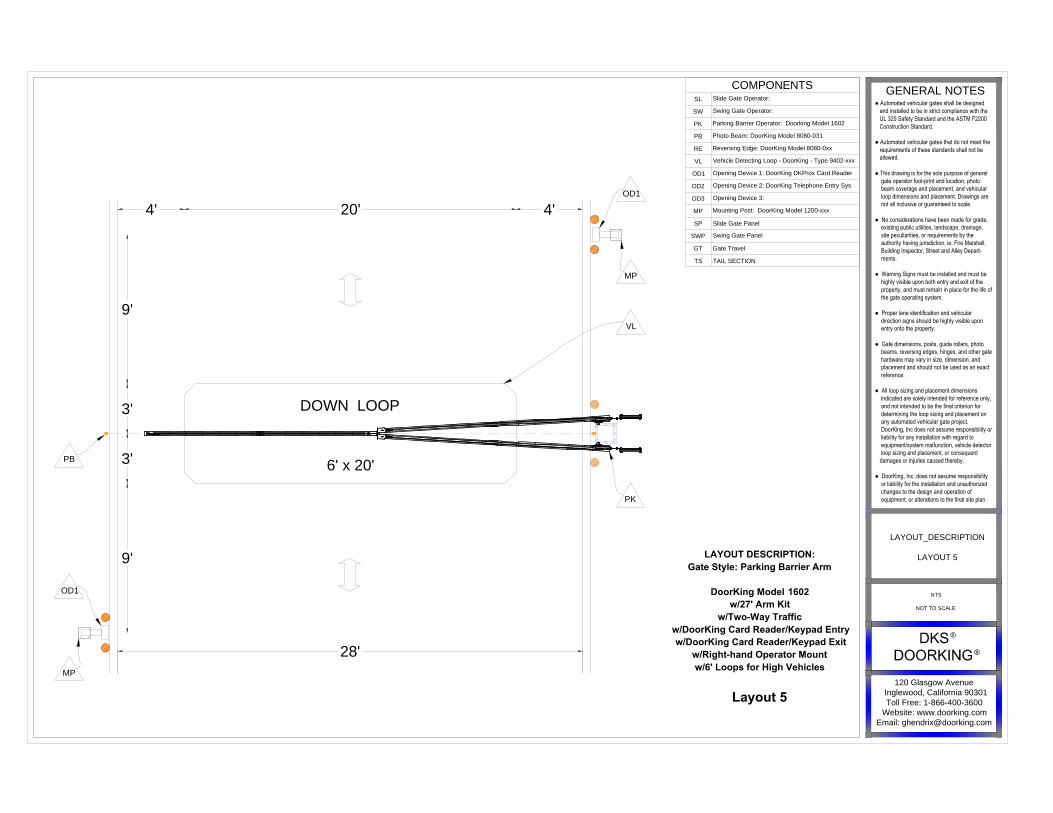
LAYOUT DESCRIPTION:
Gate Style: Parking Barrier Arm
DoorKing Model 1602
w/27' Arm Kit
w/Two-Way Traffic
w/DoorKing Card Reader/Keypad Entry
w/DoorKing Card Reader/Keypad Exit
w/Right-hand Operator Mount
w/6' Loops for High Vehicles
Layout 5
VL
OD1
MP
OD1
MP
PK
20'4' 4'
3'
9'
9'
28'
3'
DOWN LOOP
6' x 20'
PB
COMPONENTS
SL
Slide Gate Operator:
SW
Swing Gate Operator:
PK
Parking Barrier Operator: Doorking Model 1602
PB
Photo Beam: DoorKing Model 8080-031
RE
Reversing Edge: DoorKing Model 8080-0xx
VL
Vehicle Detecting Loop - DoorKing - Type 9402-xxx
OD1
Opening Device 1: DoorKing DKProx Card Reader
OD2
Opening Device 2: DoorKing Telephone Entry Sys
OD3
Opening Device 3:
MP
Mounting Post: DoorKing Model 1200-xxx
SP Slide Gate Panel
SWPSwing Gate Panel
GT Gate Travel
TS TAIL SECTION
120 Glasgow Avenue
Inglewood, California 90301
Toll Free: 1-866-400-3600
Website: www.doorking.com
Email: [email protected]
GENERAL NOTES
● Automated vehicular gates shall be designed and installed to be in strict compliance with the UL 325 Safety Standard and the ASTM F2200 Construction Standard.
● Automated vehicular gates that do not meet the requirements of these standards shall not be allowed.
● This drawing is for the sole purpose of general gate operator foot-print and location, photo beam coverage and placement, and vehicular loop dimensions and placement. Drawings are not all inclusive or guaranteed to scale.
● No considerations have been made for grade, existing public utilities, landscape, drainage, site peculiarities, or requirements by the authority having jurisdiction, ie; Fire Marshall, Building Inspector, Street and Alley Depart- ments.
● Warning Signs must be installed and must be highly visible upon both entry and exit of the property, and must remain in place for the life of the gate operating system.
● Proper lane identification and vehicular direction signs should be highly visible upon entry onto the property.
● Gate dimensions, posts, guide rollers, photo beams, reversing edges, hinges, and other gate hardware may vary in size, dimension, and placement and should not be used as an exact reference.
● All loop sizing and placement dimensions indicated are solely intended for reference only, and not intended to be the final criterion for determining the loop sizing and placement on any automated vehicular gate project. DoorKing, Inc does not assume responsibility or liability for any installation with regard to equipment/system malfunction, vehicle detector loop sizing and placement, or consequent damages or injuries caused thereby.
● DoorKing, Inc. does not assume responsibility or liability for the installation and unauthorized changes to the design and operation of equipment, or alterations to the final site plan.
LAYOUT_DESCRIPTION
LAYOUT 5
NTS
NOT TO SCALE

LAYOUT DESCRIPTION:
Gate Style: Parking Barrier Arm
DoorKing Model 1602
w/27' Arm Kit
w/Two-Way Traffic
w/DoorKing Card Reader/Keypad Entry
w/DoorKing Card Reader/Keypad Exit
w/Left-hand Operator Mount
w/6' Loops for High Vehicles
Layout 6
VL
OD1
MP
OD1
MP
20' 4'4'
3'
9'
9'
28'
3'
DOWN LOOP
6' x 20'
PB
PK
COMPONENTS
SL
Slide Gate Operator:
SW
Swing Gate Operator:
PK
Parking Barrier Operator: Doorking Model 1602
PB
Photo Beam: DoorKing Model 8080-031
RE
Reversing Edge: DoorKing Model 8080-0xx
VL
Vehicle Detecting Loop - DoorKing - Type 9402-xxx
OD1
Opening Device 1: DoorKing DKProx Card Reader
OD2
Opening Device 2: DoorKing Telephone Entry Sys
OD3
Opening Device 3:
MP
Mounting Post: DoorKing Model 1200-xxx
SP Slide Gate Panel
SWPSwing Gate Panel
GT Gate Travel
TS TAIL SECTION
120 Glasgow Avenue
Inglewood, California 90301
Toll Free: 1-866-400-3600
Website: www.doorking.com
Email: [email protected]
GENERAL NOTES
● Automated vehicular gates shall be designed and installed to be in strict compliance with the UL 325 Safety Standard and the ASTM F2200 Construction Standard.
● Automated vehicular gates that do not meet the requirements of these standards shall not be allowed.
● This drawing is for the sole purpose of general gate operator foot-print and location, photo beam coverage and placement, and vehicular loop dimensions and placement. Drawings are not all inclusive or guaranteed to scale.
● No considerations have been made for grade, existing public utilities, landscape, drainage, site peculiarities, or requirements by the authority having jurisdiction, ie; Fire Marshall, Building Inspector, Street and Alley Depart- ments.
● Warning Signs must be installed and must be highly visible upon both entry and exit of the property, and must remain in place for the life of the gate operating system.
● Proper lane identification and vehicular direction signs should be highly visible upon entry onto the property.
● Gate dimensions, posts, guide rollers, photo beams, reversing edges, hinges, and other gate hardware may vary in size, dimension, and placement and should not be used as an exact reference.
● All loop sizing and placement dimensions indicated are solely intended for reference only, and not intended to be the final criterion for determining the loop sizing and placement on any automated vehicular gate project. DoorKing, Inc does not assume responsibility or liability for any installation with regard to equipment/system malfunction, vehicle detector loop sizing and placement, or consequent damages or injuries caused thereby.
● DoorKing, Inc. does not assume responsibility or liability for the installation and unauthorized changes to the design and operation of equipment, or alterations to the final site plan.
LAYOUT_DESCRIPTION
LAYOUT 6
NTS
NOT TO SCALE

INTERIOR DOWN
LOOP
6' x 20'
LAYOUT_DESCRIPTION:
Gate Style = Parking Barrier Arm
DoorKing Model 1602
w/ 27' Arm Kit
w/ Two-Way Traffic
w/ DoorKing Card Reader/Keypad Entry
w/ Free Exit
w/ Right-hand Operator Mount
w/ 6 Loops for High Vehicles
Layout 7
DOWN LOOP
6' x 20
OPEN/EXIT
LOOP
6' x 20'
VL
VL
VL
OD1
MP
PK
20'4' 4'
3'
9'
6'
3'
28'
6'
6'
6'
PB
COMPONENTS
SL
Slide Gate Operator:
SW
Swing Gate Operator:
PK
Parking Barrier Operator: Doorking Model 1602
PB
Photo Beam: DoorKing Model 8080-031
RE
Reversing Edge: DoorKing Model 8080-0xx
VL
Vehicle Detecting Loop - DoorKing - Type 9402-xxx
OD1
Opening Device 1: DoorKing DKProx Card Reader
OD2
Opening Device 2: DoorKing Telephone Entry Sys
OD3
Opening Device 3:
MP
Mounting Post: DoorKing Model 1200-xxx
SP Slide Gate Panel
SWPSwing Gate Panel
GT Gate Travel
TS TAIL SECTION
120 Glasgow Avenue
Inglewood, California 90301
Toll Free: 1-866-400-3600
Website: www.doorking.com
Email: [email protected]
GENERAL NOTES
● Automated vehicular gates shall be designed and installed to be in strict compliance with the UL 325 Safety Standard and the ASTM F2200 Construction Standard.
● Automated vehicular gates that do not meet the requirements of these standards shall not be allowed.
● This drawing is for the sole purpose of general gate operator foot-print and location, photo beam coverage and placement, and vehicular loop dimensions and placement. Drawings are not all inclusive or guaranteed to scale.
● No considerations have been made for grade, existing public utilities, landscape, drainage, site peculiarities, or requirements by the authority having jurisdiction, ie; Fire Marshall, Building Inspector, Street and Alley Depart- ments.
● Warning Signs must be installed and must be highly visible upon both entry and exit of the property, and must remain in place for the life of the gate operating system.
● Proper lane identification and vehicular direction signs should be highly visible upon entry onto the property.
● Gate dimensions, posts, guide rollers, photo beams, reversing edges, hinges, and other gate hardware may vary in size, dimension, and placement and should not be used as an exact reference.
● All loop sizing and placement dimensions indicated are solely intended for reference only, and not intended to be the final criterion for determining the loop sizing and placement on any automated vehicular gate project. DoorKing, Inc does not assume responsibility or liability for any installation with regard to equipment/system malfunction, vehicle detector loop sizing and placement, or consequent damages or injuries caused thereby.
● DoorKing, Inc. does not assume responsibility or liability for the installation and unauthorized changes to the design and operation of equipment, or alterations to the final site plan.
LAYOUT_DESCRIPTION
LAYOUT 7
NTS
NOT TO SCALE
6'
6'
6'
6'
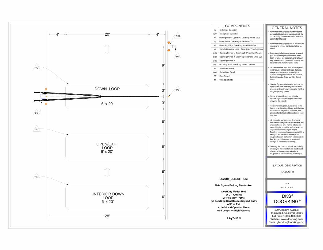
LAYOUT_DESCRIPTION:
Gate Style = Parking Barrier Arm
DoorKing Model 1602
w/ 27' Arm Kit
w/ Two-Way Traffic
w/ DoorKing Card Reader/Keypad Entry
w/ Free Exit
w/ Left-hand Operator Mount
w/ 6 Loops for High Vehicles
Layout 8
INTERIOR DOWN
LOOP
6' x 20'
DOWN LOOP
6' x 20'
OPEN/EXIT
LOOP
6' x 20'
VL
VL
VL
OD1
MP
PK
20' 4'4'
3'
9'
6'
3'
28'
PB
COMPONENTS
SL
Slide Gate Operator:
SW
Swing Gate Operator:
PK
Parking Barrier Operator: Doorking Model 1602
PB
Photo Beam: DoorKing Model 8080-031
RE
Reversing Edge: DoorKing Model 8080-0xx
VL
Vehicle Detecting Loop - DoorKing - Type 9402-xxx
OD1
Opening Device 1: DoorKing DKProx Card Reader
OD2
Opening Device 2: DoorKing Telephone Entry Sys
OD3
Opening Device 3:
MP
Mounting Post: DoorKing Model 1200-xxx
SP Slide Gate Panel
SWPSwing Gate Panel
GT Gate Travel
TS TAIL SECTION
120 Glasgow Avenue
Inglewood, California 90301
Toll Free: 1-866-400-3600
Website: www.doorking.com
Email: [email protected]
GENERAL NOTES
● Automated vehicular gates shall be designed and installed to be in strict compliance with the UL 325 Safety Standard and the ASTM F2200 Construction Standard.
● Automated vehicular gates that do not meet the requirements of these standards shall not be allowed.
● This drawing is for the sole purpose of general gate operator foot-print and location, photo beam coverage and placement, and vehicular loop dimensions and placement. Drawings are not all inclusive or guaranteed to scale.
● No considerations have been made for grade, existing public utilities, landscape, drainage, site peculiarities, or requirements by the authority having jurisdiction, ie; Fire Marshall, Building Inspector, Street and Alley Depart- ments.
● Warning Signs must be installed and must be highly visible upon both entry and exit of the property, and must remain in place for the life of the gate operating system.
● Proper lane identification and vehicular direction signs should be highly visible upon entry onto the property.
● Gate dimensions, posts, guide rollers, photo beams, reversing edges, hinges, and other gate hardware may vary in size, dimension, and placement and should not be used as an exact reference.
● All loop sizing and placement dimensions indicated are solely intended for reference only, and not intended to be the final criterion for determining the loop sizing and placement on any automated vehicular gate project. DoorKing, Inc does not assume responsibility or liability for any installation with regard to equipment/system malfunction, vehicle detector loop sizing and placement, or consequent damages or injuries caused thereby.
● DoorKing, Inc. does not assume responsibility or liability for the installation and unauthorized changes to the design and operation of equipment, or alterations to the final site plan.
LAYOUT_DESCRIPTION
LAYOUT 8
NTS
NOT TO SCALE

DOWN LOOP
6' x 20'
LAYOUT DESCRIPTION:
Gate Style: Parking Barrier Arm
DoorKing Model 1602
w/27' Arm Kit
w/One-Way Entrance or Exit Drive
w/DoorKing Card Reader/Keypad
w/Bi-parting Operator Mount
w/6' Loops for High Vehicles
Layout 9
VL VL
OD1
MP
PKPK
4'-6" 20' 4'-6"
3'
9'
3'
54'
DOWN LOOP
6' x 20'
20' 5'
COMPONENTS
SL
Slide Gate Operator:
SW
Swing Gate Operator:
PK
Parking Barrier Operator: Doorking Model 1602
PB
Photo Beam: DoorKing Model 8080-031
RE
Reversing Edge: DoorKing Model 8080-0xx
VL
Vehicle Detecting Loop - DoorKing - Type 9402-xxx
OD1
Opening Device 1: DoorKing DKProx Card Reader
OD2
Opening Device 2: DoorKing Telephone Entry Sys
OD3
Opening Device 3:
MP
Mounting Post: DoorKing Model 1200-xxx
SP Slide Gate Panel
SWP
Swing Gate Panel
GT Gate Travel
TS TAIL SECTION
120 Glasgow Avenue
Inglewood, California 90301
Toll Free: 1-866-400-3600
Website: www.doorking.com
Email: [email protected]
GENERAL NOTES
● Automated vehicular gates shall be designed and installed to be in strict compliance with the UL 325 Safety Standard and the ASTM F2200 Construction Standard.
● Automated vehicular gates that do not meet the requirements of these standards shall not be allowed.
● This drawing is for the sole purpose of general gate operator foot-print and location, photo beam coverage and placement, and vehicular loop dimensions and placement. Drawings are not all inclusive or guaranteed to scale.
● No considerations have been made for grade, existing public utilities, landscape, drainage, site peculiarities, or requirements by the authority having jurisdiction, ie; Fire Marshall, Building Inspector, Street and Alley Depart- ments.
● Warning Signs must be installed and must be highly visible upon both entry and exit of the property, and must remain in place for the life of the gate operating system.
● Proper lane identification and vehicular direction signs should be highly visible upon entry onto the property.
● Gate dimensions, posts, guide rollers, photo beams, reversing edges, hinges, and other gate hardware may vary in size, dimension, and placement and should not be used as an exact reference.
● All loop sizing and placement dimensions indicated are solely intended for reference only, and not intended to be the final criterion for determining the loop sizing and placement on any automated vehicular gate project. DoorKing, Inc does not assume responsibility or liability for any installation with regard to equipment/system malfunction, vehicle detector loop sizing and placement, or consequent damages or injuries caused thereby.
● DoorKing, Inc. does not assume responsibility or liability for the installation and unauthorized changes to the design and operation of equipment, or alterations to the final site plan.
LAYOUT_DESCRIPTION
LAYOUT 9
NTS
NOT TO SCALE
LAYOUT DESCRIPTION:
Gate Style: Parking Barrier Arm
DoorKing Model 1602
w/27' Arm Kit
w/One-Way Exit Drive
w/Bi-parting Operator Mount
w/6' Loops for High Vehicles
Layout 10
OPEN/EXIT
LOOP
6' x 20'
OPEN/EXIT
LOOP
6' x 20'
VL
VL
PK
PK
54'
PBPB
VLVL
5' 20' 5'20' 4'
3'
3'
8'
6'
DOWN LOOP
6' x 20'
DOWN LOOP
6' x 20'
COMPONENTS
SL
Slide Gate Operator:
SW
Swing Gate Operator:
PK
Parking Barrier Operator: Doorking Model 1602
PB
Photo Beam: DoorKing Model 8080-031
RE
Reversing Edge: DoorKing Model 8080-0xx
VL
Vehicle Detecting Loop - DoorKing - Type 9402-xxx
OD1
Opening Device 1: DoorKing DKProx Card Reader
OD2
Opening Device 2: DoorKing Telephone Entry Sys
OD3
Opening Device 3:
MP
Mounting Post: DoorKing Model 1200-xxx
SP Slide Gate Panel
SWPSwing Gate Panel
GT Gate Travel
TS TAIL SECTION
120 Glasgow Avenue
Inglewood, California 90301
Toll Free: 1-866-400-3600
Website: www.doorking.com
Email: [email protected]
GENERAL NOTES
● Automated vehicular gates shall be designed and installed to be in strict compliance with the UL 325 Safety Standard and the ASTM F2200 Construction Standard.
● Automated vehicular gates that do not meet the requirements of these standards shall not be allowed.
● This drawing is for the sole purpose of general gate operator foot-print and location, photo beam coverage and placement, and vehicular loop dimensions and placement. Drawings are not all inclusive or guaranteed to scale.
● No considerations have been made for grade, existing public utilities, landscape, drainage, site peculiarities, or requirements by the authority having jurisdiction, ie; Fire Marshall, Building Inspector, Street and Alley Depart- ments.
● Warning Signs must be installed and must be highly visible upon both entry and exit of the property, and must remain in place for the life of the gate operating system.
● Proper lane identification and vehicular direction signs should be highly visible upon entry onto the property.
● Gate dimensions, posts, guide rollers, photo beams, reversing edges, hinges, and other gate hardware may vary in size, dimension, and placement and should not be used as an exact reference.
● All loop sizing and placement dimensions indicated are solely intended for reference only, and not intended to be the final criterion for determining the loop sizing and placement on any automated vehicular gate project. DoorKing, Inc does not assume responsibility or liability for any installation with regard to equipment/system malfunction, vehicle detector loop sizing and placement, or consequent damages or injuries caused thereby.
● DoorKing, Inc. does not assume responsibility or liability for the installation and unauthorized changes to the design and operation of equipment, or alterations to the final site plan.
LAYOUT_DESCRIPTION
LAYOUT 10
NTS
NOT TO SCALE

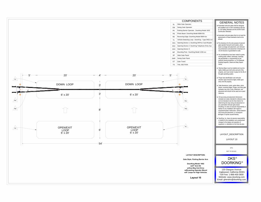
LAYOUT DESCRIPTION:
Gate Style: Parking Barrier Arm
DoorKing Model 1602
w/27' Arm Kit
w/Two-Way Traffice
w/DoorKing Card Reader/Keypad Entry
w/DoorKing Card Reader/Keypad Exit
w/Bi-parting Operator Mount
w/6' Loops for High Vehicles
Layout 11
OD1
MP
PKPK
9'
9'
5'
3'
3'
20' 20'
54'
OD1
MP
4'
PBPB
VL
VL
5'
DOWN LOOP
6' x 20'
DOWN LOOP
6' x 20'
COMPONENTS
SLSlide Gate Operator:
SW
Swing Gate Operator:
PK
Parking Barrier Operator: Doorking Model 1602
PB
Photo Beam: DoorKing Model 8080-031
RE
Reversing Edge: DoorKing Model 8080-0xx
VL
Vehicle Detecting Loop - DoorKing - Type 9402-xxx
OD1
Opening Device 1: DoorKing DKProx Card Reader
OD2
Opening Device 2: DoorKing Telephone Entry Sys
OD3Opening Device 3:
MP
Mounting Post: DoorKing Model 1200-xxx
SP Slide Gate Panel
SWP
Swing Gate Panel
GT Gate Travel
TS TAIL SECTION
120 Glasgow Avenue
Inglewood, California 90301
Toll Free: 1-866-400-3600
Website: www.doorking.com
Email: [email protected]
GENERAL NOTES
● Automated vehicular gates shall be designed and installed to be in strict compliance with the UL 325 Safety Standard and the ASTM F2200 Construction Standard.
● Automated vehicular gates that do not meet the requirements of these standards shall not be allowed.
● This drawing is for the sole purpose of general gate operator foot-print and location, photo beam coverage and placement, and vehicular loop dimensions and placement. Drawings are not all inclusive or guaranteed to scale.
● No considerations have been made for grade, existing public utilities, landscape, drainage, site peculiarities, or requirements by the authority having jurisdiction, ie; Fire Marshall, Building Inspector, Street and Alley Depart- ments.
● Warning Signs must be installed and must be highly visible upon both entry and exit of the property, and must remain in place for the life of the gate operating system.
● Proper lane identification and vehicular direction signs should be highly visible upon entry onto the property.
● Gate dimensions, posts, guide rollers, photo beams, reversing edges, hinges, and other gate hardware may vary in size, dimension, and placement and should not be used as an exact reference.
● All loop sizing and placement dimensions indicated are solely intended for reference only, and not intended to be the final criterion for determining the loop sizing and placement on any automated vehicular gate project. DoorKing, Inc does not assume responsibility or liability for any installation with regard to equipment/system malfunction, vehicle detector loop sizing and placement, or consequent damages or injuries caused thereby.
● DoorKing, Inc. does not assume responsibility or liability for the installation and unauthorized changes to the design and operation of equipment, or alterations to the final site plan.
LAYOUT_DESCRIPTION
Layout 11
NTS
NOT TO SCALE
LAYOUT DESCRIPTION:
Gate Style:Parking Barrier Arm
DoorKing Model 1602
w/27' Arm Kit
w/Two-Way Drive
w/DoorKing Card Reader/Keypad Entry
w/Free Exit
w/Bi-parting Operator Mount
w/6'Loops for High Vehicles
Layout 12
6'
6'
6'
INTERIOR DOWN
LOOP
6' x 20'
INTERIOR DOWN
LOOP
6' x 20'
VL
VL
VL
VL
VL
VL
PKPK
20' 4'5' 20' 5'
3'
9'
6'
3'
OD1
MP
PB
PB
54'
DOWN LOOP
6' x 20'
DOWN LOOP
6' x 20'
OPEN/EXIT
LOOP
6' x 20'
OPEN/EXIT
LOOP
6' x 20'
COMPONENTS
SLSlide Gate Operator:
SW
Swing Gate Operator:
PK
Parking Barrier Operator: Doorking Model 1602
PB
Photo Beam: DoorKing Model 8080-031
RE
Reversing Edge: DoorKing Model 8080-0xx
VL
Vehicle Detecting Loop - DoorKing - Type 9402-xxx
OD1
Opening Device 1: DoorKing DKProx Card Reader
OD2
Opening Device 2: DoorKing Telephone Entry Sys
OD3Opening Device 3:
MP
Mounting Post: DoorKing Model 1200-xxx
SP Slide Gate Panel
SWP
Swing Gate Panel
GT Gate Travel
TS TAIL SECTION
120 Glasgow Avenue
Inglewood, California 90301
Toll Free: 1-866-400-3600
Website: www.doorking.com
Email: [email protected]
GENERAL NOTES
● Automated vehicular gates shall be designed and installed to be in strict compliance with the UL 325 Safety Standard and the ASTM F2200 Construction Standard.
● Automated vehicular gates that do not meet the requirements of these standards shall not be allowed.
● This drawing is for the sole purpose of general gate operator foot-print and location, photo beam coverage and placement, and vehicular loop dimensions and placement. Drawings are not all inclusive or guaranteed to scale.
● No considerations have been made for grade, existing public utilities, landscape, drainage, site peculiarities, or requirements by the authority having jurisdiction, ie; Fire Marshall, Building Inspector, Street and Alley Depart- ments.
● Warning Signs must be installed and must be highly visible upon both entry and exit of the property, and must remain in place for the life of the gate operating system.
● Proper lane identification and vehicular direction signs should be highly visible upon entry onto the property.
● Gate dimensions, posts, guide rollers, photo beams, reversing edges, hinges, and other gate hardware may vary in size, dimension, and placement and should not be used as an exact reference.
● All loop sizing and placement dimensions indicated are solely intended for reference only, and not intended to be the final criterion for determining the loop sizing and placement on any automated vehicular gate project. DoorKing, Inc does not assume responsibility or liability for any installation with regard to equipment/system malfunction, vehicle detector loop sizing and placement, or consequent damages or injuries caused thereby.
● DoorKing, Inc. does not assume responsibility or liability for the installation and unauthorized changes to the design and operation of equipment, or alterations to the final site plan.
LAYOUT_DESCRIPTION
Layput 12
NTS
NOT TO SCALE
COMPONENTS
SL
Slide Gate Operator:
SW
Swing Gate Operator:
PK
Parking Barrier Operator: Doorking Model 1602
PB
Photo Beam: DoorKing Model 8080-031
RE
Reversing Edge: DoorKing Model 8080-0xx
VL
Vehicle Detecting Loop - DoorKing - Type 9402-xxx
OD1
Opening Device 1: DoorKing DKProx Card Reader
OD2
Opening Device 2: DoorKing Telephone Entry Sys
OD3
Opening Device 3:
MP
Mounting Post: DoorKing Model 1200-xxx
SP Slide Gate Panel
SWP
Swing Gate Panel
GT Gate Travel
TS TAIL SECTION
120 Glasgow Avenue
Inglewood, California 90301
Toll Free: 1-866-400-3600
Website: www.doorking.com
Email: [email protected]
GENERAL NOTES
● Automated vehicular gates shall be designed and installed to be in strict compliance with the UL 325 Safety Standard and the ASTM F2200 Construction Standard.
● Automated vehicular gates that do not meet the requirements of these standards shall not be allowed.
● This drawing is for the sole purpose of general gate operator foot-print and location, photo beam coverage and placement, and vehicular loop dimensions and placement. Drawings are not all inclusive or guaranteed to scale.
● No considerations have been made for grade, existing public utilities, landscape, drainage, site peculiarities, or requirements by the authority having jurisdiction, ie; Fire Marshall, Building Inspector, Street and Alley Depart- ments.
● Warning Signs must be installed and must be highly visible upon both entry and exit of the property, and must remain in place for the life of the gate operating system.
● Proper lane identification and vehicular direction signs should be highly visible upon entry onto the property.
● Gate dimensions, posts, guide rollers, photo beams, reversing edges, hinges, and other gate hardware may vary in size, dimension, and placement and should not be used as an exact reference.
● All loop sizing and placement dimensions indicated are solely intended for reference only, and not intended to be the final criterion for determining the loop sizing and placement on any automated vehicular gate project. DoorKing, Inc does not assume responsibility or liability for any installation with regard to equipment/system malfunction, vehicle detector loop sizing and placement, or consequent damages or injuries caused thereby.
● DoorKing, Inc. does not assume responsibility or liability for the installation and unauthorized changes to the design and operation of equipment, or alterations to the final site plan.
LAYOUT_DESCRIPTION
Layout 13
NTS
NOT TO SCALE
COMPONENTS
SLSlide Gate Operator:
SW
Swing Gate Operator:
PK
Parking Barrier Operator: Doorking Model 1602
PB
Photo Beam: DoorKing Model 8080-031
RE
Reversing Edge: DoorKing Model 8080-0xx
VL
Vehicle Detecting Loop - DoorKing - Type 9402-xxx
OD1
Opening Device 1: DoorKing DKProx Card Reader
OD2
Opening Device 2: DoorKing Telephone Entry Sys
OD3Opening Device 3:
MP
Mounting Post: DoorKing Model 1200-xxx
SP Slide Gate Panel
SWP
Swing Gate Panel
GT Gate Travel
TS TAIL SECTION
120 Glasgow Avenue
Inglewood, California 90301
Toll Free: 1-866-400-3600
Website: www.doorking.com
Email: [email protected]
GENERAL NOTES
● Automated vehicular gates shall be designed and installed to be in strict compliance with the UL 325 Safety Standard and the ASTM F2200 Construction Standard.
● Automated vehicular gates that do not meet the requirements of these standards shall not be allowed.
● This drawing is for the sole purpose of general gate operator foot-print and location, photo beam coverage and placement, and vehicular loop dimensions and placement. Drawings are not all inclusive or guaranteed to scale.
● No considerations have been made for grade, existing public utilities, landscape, drainage, site peculiarities, or requirements by the authority having jurisdiction, ie; Fire Marshall, Building Inspector, Street and Alley Depart- ments.
● Warning Signs must be installed and must be highly visible upon both entry and exit of the property, and must remain in place for the life of the gate operating system.
● Proper lane identification and vehicular direction signs should be highly visible upon entry onto the property.
● Gate dimensions, posts, guide rollers, photo beams, reversing edges, hinges, and other gate hardware may vary in size, dimension, and placement and should not be used as an exact reference.
● All loop sizing and placement dimensions indicated are solely intended for reference only, and not intended to be the final criterion for determining the loop sizing and placement on any automated vehicular gate project. DoorKing, Inc does not assume responsibility or liability for any installation with regard to equipment/system malfunction, vehicle detector loop sizing and placement, or consequent damages or injuries caused thereby.
● DoorKing, Inc. does not assume responsibility or liability for the installation and unauthorized changes to the design and operation of equipment, or alterations to the final site plan.
LAYOUT_DESCRIPTION
Layput 14
NTS
NOT TO SCALE


![Untitled Document []me3200/hws/F02HWS/F02_HW1.pdf2. When the brake pad contacts the wheel rim we could consider the joint between the pad, which is rigidly attached to the brake arm](https://img.pdfslide.net/doc/110x75/5e9700f0302f15767300d74a/untitled-document-me3200hwsf02hwsf02hw1pdf-2-when-the-brake-pad-contacts.jpg)