Embed Size (px)
Citation preview
ED 021 742By- Balabanian. NormanOFIIIS LAW AND ELECTRICAL SOURCES, A PROGRAMMED TEXT.Syracuse Univ. N.Y. Dept. of Electrical Engineering.Spons Agency- Office of Education (DHEW), Washington, D.C. Bureau of ResearthReport No-2Bureau No- BR-5-0796Pub Date 63Contract- OEC- 4- 10-102Note- 82p.EDRS Price MF-S0.50 HC-S336Descriptors-*COLLEGE SCIENCE ELECTRICITY, *ELECTRONICS, *ENGINEERING EDUCATION. *INSTRUCTIONALMATERIALS PHYSICAL SCIENCES *PROGRAMED INSTRUCTIOR TEXTBOOKS, UNDERGRADUATE STUDY
Identifiers- Syracuse University, United States Office of EducationThis proGramed textbook was developed under contract with the United States
Office of Education as Number 2 of a series of materials for use in an electricalengineering sequence. It is divided into five parts--(1) Ohm's Law. (2) resistance, (3)conductance, (4) voltage sources, and (5) current sources. (OH)
DOCUMENT RESUME
24 SE 004 649
I
U.S
. DE
PA
RT
ME
NT
OF
HE
ALT
H, E
DU
CA
TIO
N&
WE
LFA
RE
OF
FIC
E O
F E
DU
CA
TIO
N
TH
IS D
OC
UM
EN
T H
AS
BE
EN
RE
PR
OD
UC
ED
EX
AC
TLY
AS
RE
CE
IVE
D F
RO
M T
HE
PE
RS
ON
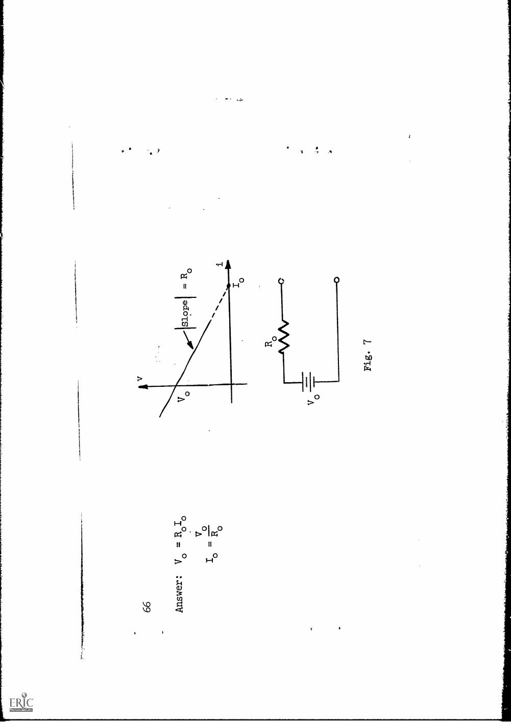
OR
OR
GA
NIZ
AT
ION
OR
IGIN
AT
ING
IT. _
PO
INT
S O
f VIE
W O
R O
PIN
ION
S
ST
AT
ED
DO
NO
T N
EC
ES
SA
RIL
Y R
EP
RE
SE
NT
OF
FIC
IAL
OF
FIC
E O
F E
DU
CA
TIO
N
RA
MO
N O
R P
OLI
CY
.A
Pro
gram
med
Tex
t
OH
M'S
LA
W A
ND
EL
EC
TR
ICA
L S
OU
RC
ES
by'
Norman Balabanian
Electrical Engineering Department
Syracuse University
Contract No. OE -10-102
U.S. Office of Education
Copyright (C) 1963
(3rd Edition)
8A-E
-617
q1
?tf-
"PE
RM
ISS
ION
TO
RE
PR
OD
UC
E T
HIS
CO
PY
RIG
HT
ED
MA
TE
RIA
L H
AS
BE
EN
GR
AN
TE
D
BY
Lfi
e
TO
ER
IC A
ND
OR
GA
NIZ
AT
ION
S O
PE
RA
TIN
GU
ND
ER
AG
RE
EM
EN
TS
WIT
H T
HE
U.S
. OF
FIC
E O
F
ED
UC
AT
ION
. FU
RT
HE
R R
EP
RO
DU
CT
ION
OU
TS
IDE
TH
E E
RIC
SY
ST
EM
RE
OU
IRE
S P
ER
MIS
SIO
N O
F
TH
E C
OP
YR
IGH
T O
WN
ER
."
Table of Contents
Page,
Ohm's Law
1
Resistor, Resistance
13
Conductance
21
Sources (Voltage Source)
31
Current Source
57
1
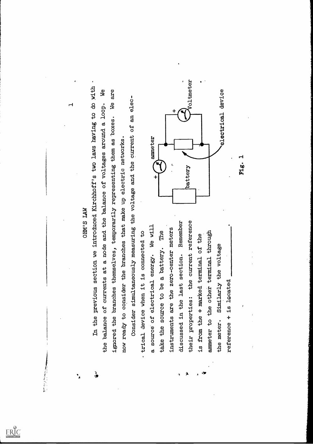
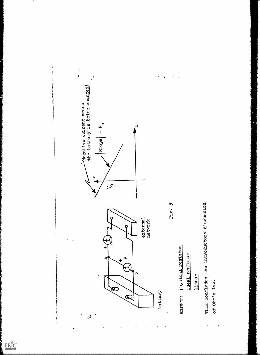
OHM'S LAW
In the previous section we introduced.
Kir
chho
ff's
two laws having to do Nith -
the balance of currents at a node and the balance
of voltages around a loop.
We
ignored the branches themselves, temporarily representing
them as boxes.
We are
now ready to consider the branches thatmake up electric networks.
Consider simultaneously measuring the voltage and
the current of an elec-
- trical devicewhen it is connected to
a source of electrical energy.
We will
ammeter
take the source to be a battery.
The
instruments are the zero-center meters
discussed in the last section.
Remember
their properties:
the current reference
W oltmeter
is from the + marked terminal of the
ammeter to the other terminal through
the meter.
Similarly the voltage
elec
tric
aldevice
reference + is located
Fig. 1
2 Answer:
at the + marked-terminal of the voltmeter
(a)
Fig. 2
(-i11-v1
)
v (b)
i
3
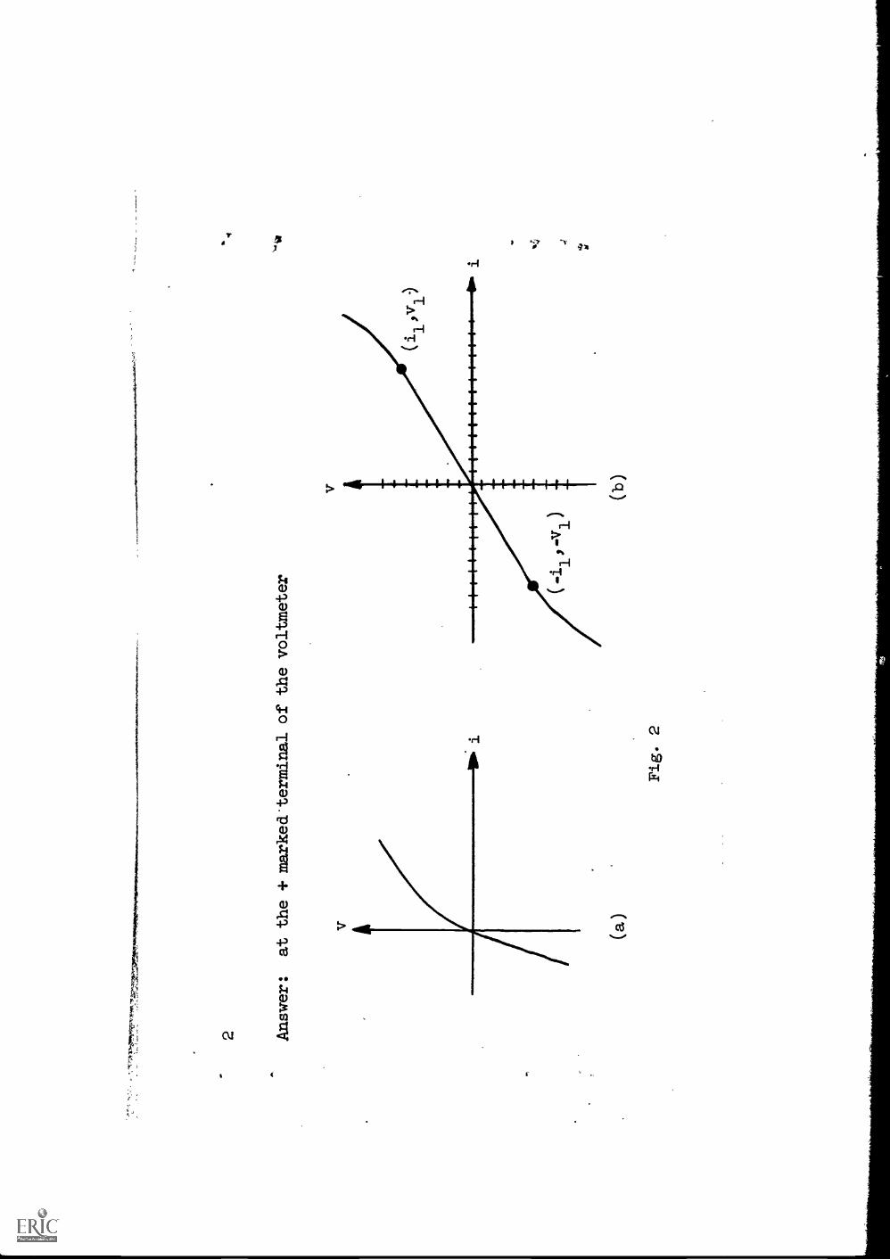
If the described measurements are
made on a large number of
different devices,
and a graph is made ofthe-voltage plqtted against
the current for each one, anumber
of different curves will result.
Two possible curves are
shown.
Figure 2(a) results whenmeasurements aremade
on a device called a
diode.
(Consideration of this will be deferredto a later sec-
tion.) Other devices, notably metallic
objects or lengths of wire,
lead to curves
like that in Fig.
2(b).
Note the characteristics
of this curve, Fig.
2(b):
.
_
(1)
When the current
jc positive, the voltage is
and when the
current is negative the voltage is
(2)
The curve is symmetrical aboutthe origin, in that if vl
is the voltage
for a positive current i1'
the voltage for a current
-i1
is
Note carefully the mannerin which the instruments are
connected in Fig. 1.
We assume further that the
instruments are ideal:
that is, although current
is
flowing through the ammeter, there
is no voltage across it
and although there is
a voltage across
the voltmeters there is no
current through it.
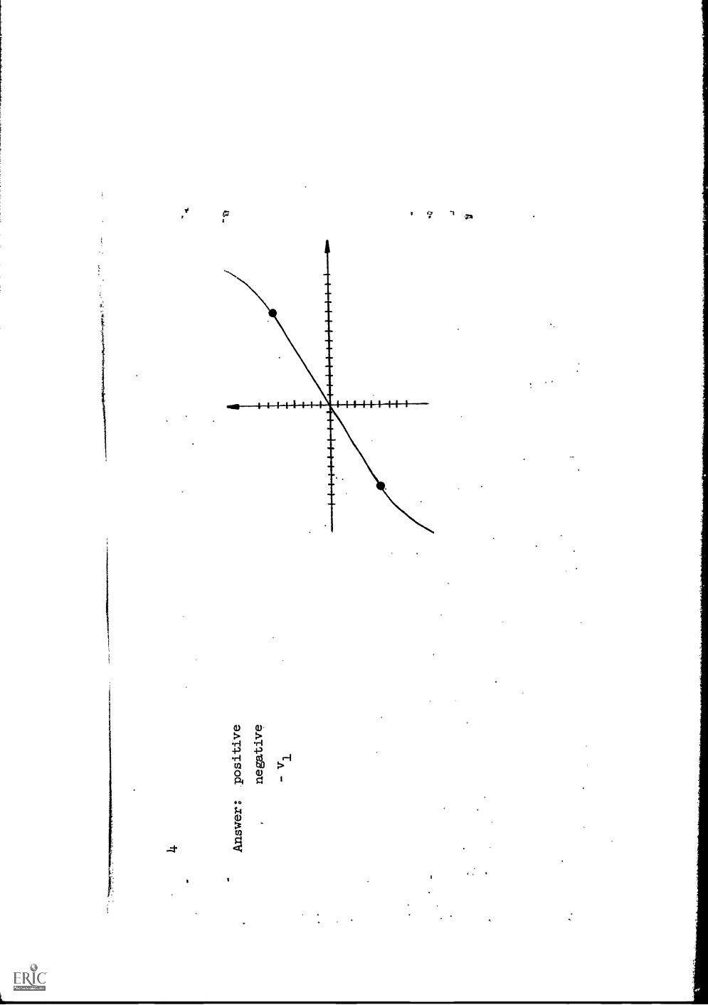
14. Answer:
Tositive
negative
-vl
5
Another.characteristic of the curve,
Fig. 2(b), is that,
for a range
'of positive and negative
values around zero current,
the curve is approxi-
mately a straight line.
Now if the coordinates were xand y instead of i
and v, you would no
doubt agree that the equationof the straight line
could be written as
Y =
6 Answer:
y = mx,
where m'is a constant equalto the slope of the
line.
This expression is called, a
linear equation.

From memory, drawthe approximatelylinear v-i curve wehave been dis-
cussing.
In the range of small
current magnitudes the equationrelating v to i
can be written as
8 Ans
wer
:v
= W
., w
here
Ris
a c
onst
ant.
(You
may
hav
e us
ed a
diff
eren
t sym
bol,
such
as
m f
or th
eco
nsta
nt R
I w
hich
is O
K, b
ut le
t's u
seR
fro
m r
iow
on.
)vt
it

..
9
The equation v = Rirepresents a straight
line passing through
the origin;
it is called a
equation.
10 Answer:
linear
w
.4
4
.;
v-s-
11
Remember that the linear relationship
between v and i extends only over a
finite range of current.
But the linear equation is so simple
and easy to
handle, 'we cannot butwish that there were a device having
such a voltage-
current relationship.
We therefore imagine, or mentally
invent, a hypothetical
device whose v-i relationship we assign
to be, or Dostulate to be,
(Give an equation.)
r
12 Ans
wer
v =
Ri
13
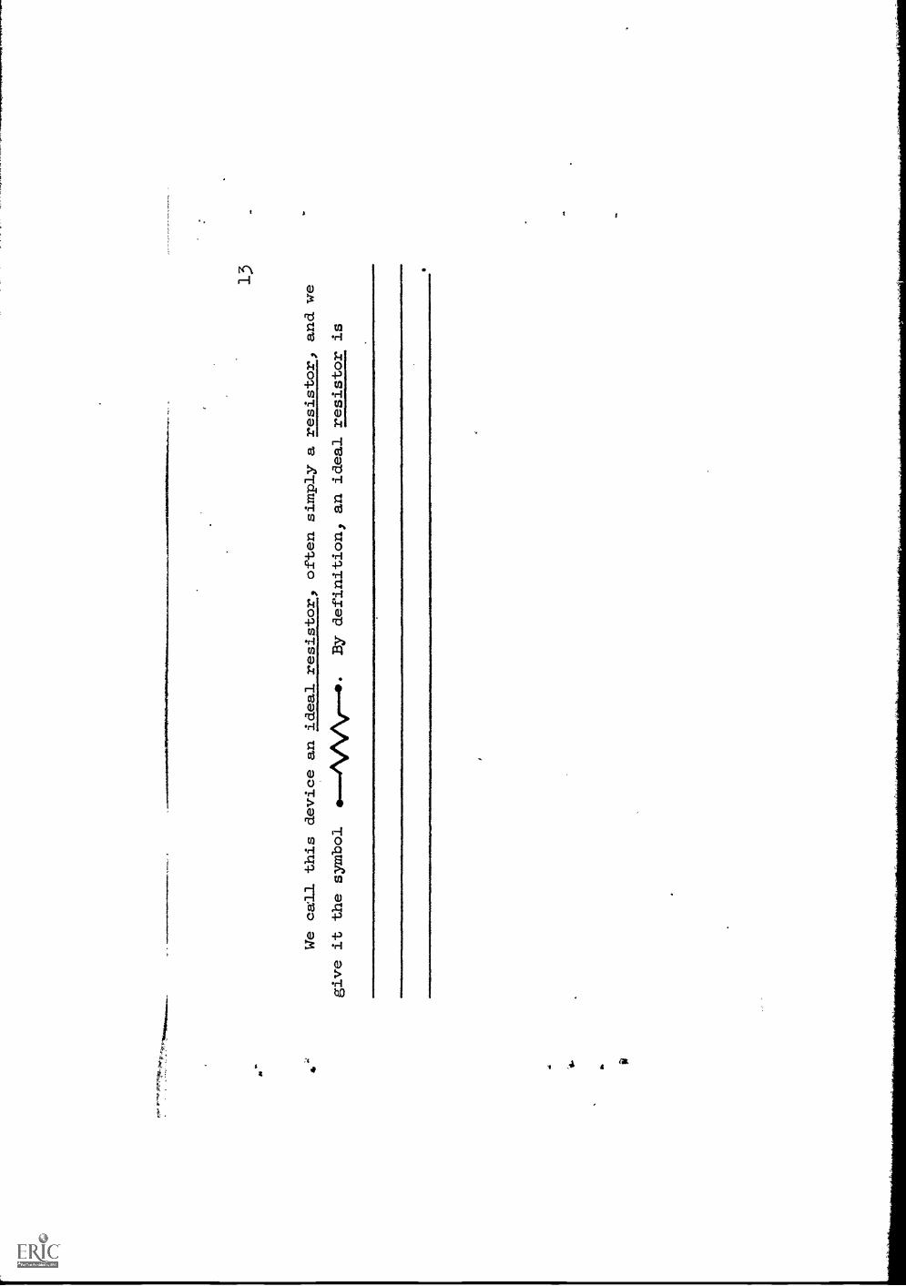
We call this device an ideal resistor, often simply a resistor, and we
give it the symbol
..-...4VOSINI-4P.
By definition, an ideal resistor is

:
Answer:
A hypothetical
(electrical) device postulated to have(or havin)
the voltage-current
relationship v = Ri.
NOTE: Be sure your definition
included something about
1.
A resistor is assumed tohave certain properties,
and
2.
The equation v = R. describes a
linear relationship.
Do not include anything
about the effect of time
variation.
Go back and change your
definition, as may be
appropriate.
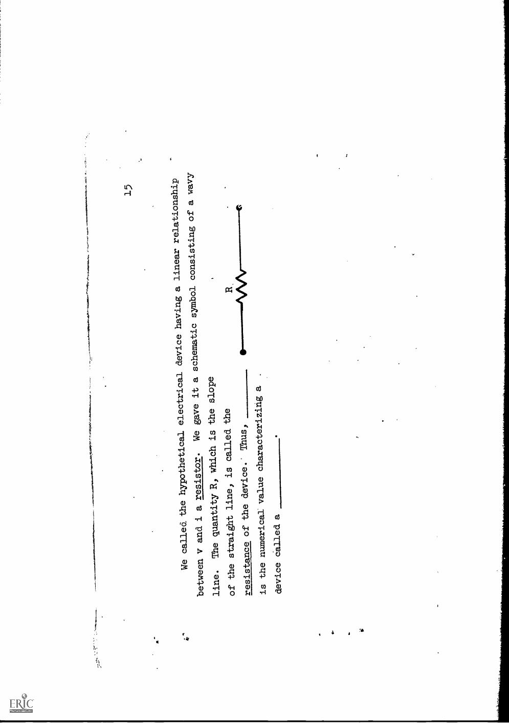
15
We called thehypothetical electrical
device having a
linear relationship
between v and i aresistor.
We gave it aschematic symbol
consisting of a wavy
line.
The quantity:RI
which is the slope
of the straight
line, is calledthe
resistance of the
device.
Thus,
is the numericalvalue characterizing a
device called a

16
Answer:
resistance
resistor

17
Since;(with the instruments connectedas in Fig. 1) the slope of the straight
_
line Is positive, the resistance isa,positive quantity.
When a resistor is in a circuit supplied by sources) there will normally be
a current through it and a voltage across it.
Since there are .two alternatives
'for choosing the voltage reference and two for the current reference, there will
,be a total of four possible combinations for the voltage and current references
togetherl.as shown in the diagram be163.
Of these four there are only two distinctly different combinations, as
rotating sui
of them 180 degrees will show.
Which pairs are the same?
(a)
(b)
(c)
(d)

18
Answer:
a and. d. are the same
b and. c are the same
+ V
I0
(a)
(b)
.4 le
19
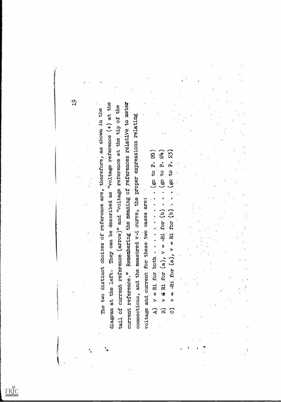
The two distinct choices Ofreference are, thereforel-as shown inthe
diagram at the left.
They can be described as 'voltage
reference (-0 at the
tail Of current reference
(arrow)" and "voltage reference at the tip ofthe
current reference." RememberingAhemeaning of references relative tometer
connections, and the measilred v-i.curvel
the proper expressions relating
voltage and current for these
twO cases are:
A)
v = Ri for both ....
..
.(go to. P. 20)
B)
v 4 Ri for
(a), v =
for (b)
..
.(go to P. 24.)
C)
v = -Ri.for
(a), v
= Ri for
(b)
..(go to P. 23)
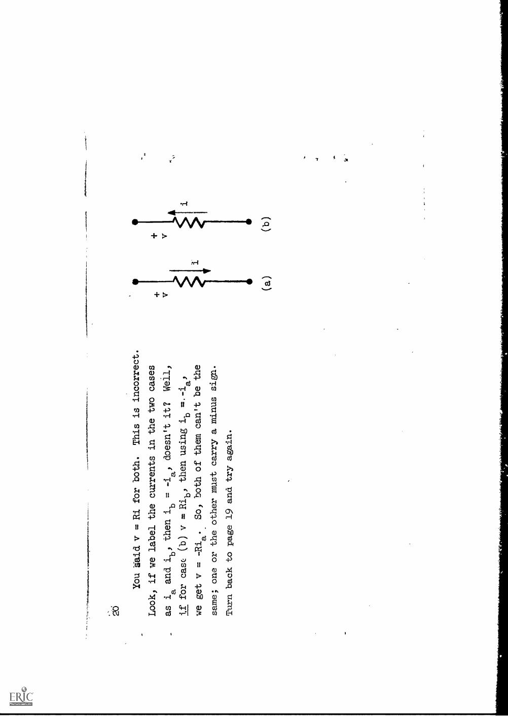
You 'Said v = Ri for both.
This is incorrect.
Look, if we label the currents in the two cases
as i
and ib'
then i
= -ia
doesn't it?
Well,
aif for case (b) v = Ribl
then using
awe get v =
So, both of them can't be the
same; one or the other must carry a minus sign.
Turn back to page 19 and try again.
(a)
(b)
21
As we have written Ohm's law, v is expressed in terms of i.
It is possible
1of course, to invert this expression and write i
.v which is just another
form of Ohm's law.
It is convenient to give the reciprocal of R a name; we
1call 1/R conductance and give it the symbol G: G =
and i = Gv.
Conductance is the
cr: resistance.
The unit in which conductance
is measured is bbtained by spelling backwards the unit in which resistance is
measured; that is, the unit of G is a
.1.1
*

22
Answer:
reciprocal
mho
(go to pag
1.
et
23
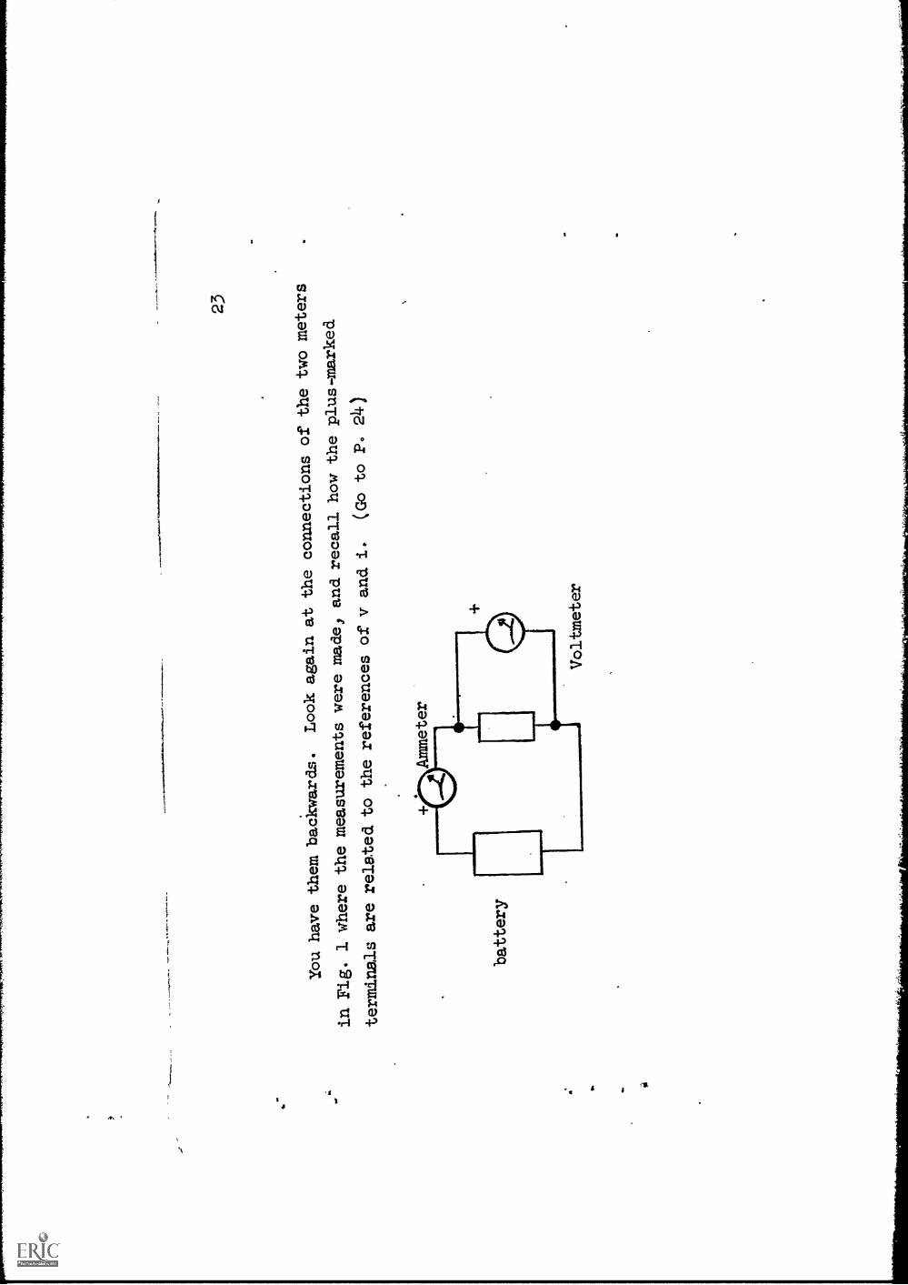
You have thembackwards.
Look again at the
connections of the twometers
in Fig. 1 where themeasurements were made,
and recall how theplus-marked
terminals are related to
the references of v
and i.
(Go to P. 24)
battery
1%,
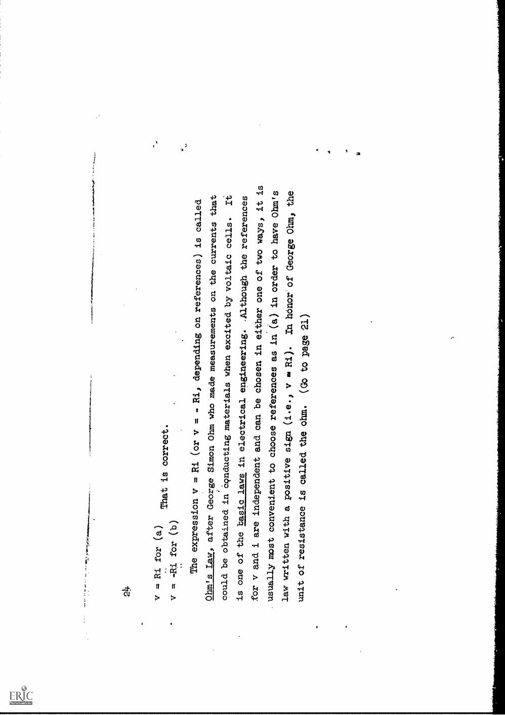
v = Ri for (a)
That is correct.
v = -Ri for (b)
The expression v
= Ri (or v =
Ri, depending on references) is
called
Ohm's Law, after George Simon
Ohm who made measurements
on the currents that
could be obtained in 69nductingmaterials when excited by voltaic
cells.
Ii
is one of the basic laws in
electrical engineering. ,Althoughthe references
for v and i are independentand can be chosen in either
one of two ways, it is
.
usually most convenient to
choose references
as in (a) in order to have Ohm's
law written witha positive sign (i.e., v
Ri).
In honor'of George Ohm, the
unit of resistance is
called the ohm.
(Go to pagela)
Sf

25
For the resistor shown there
is a voltage v = 100 voltswhen the current
is i = 2 milliamperes. 1110Pre.
+v
NA
&
The conductance and resistance are:
a)
conductance G =
b)
resistance R =
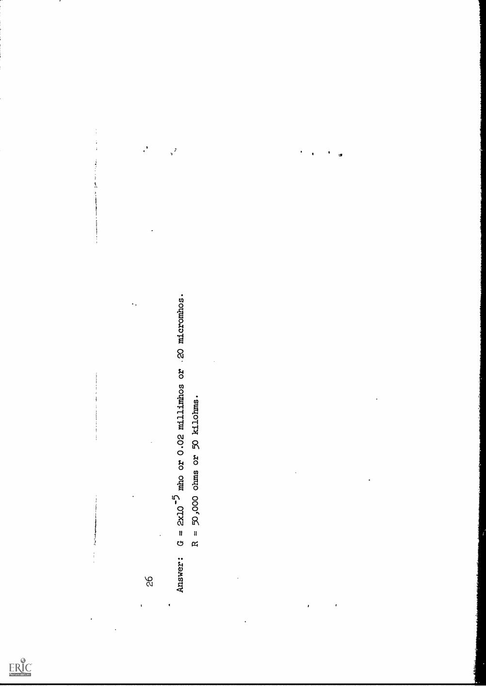
26
Answer:
G = 2x10⁻⁵mho or 0.02 millimhos or .20 micromhos.
R = 50,000 ohms or 50 kilohms.

If the resistance R in the diagram is
100 kilohms and the voltage v is
(5 sin 100t)
volts) what is the current 13
(Expresv; in
microamps.)
27
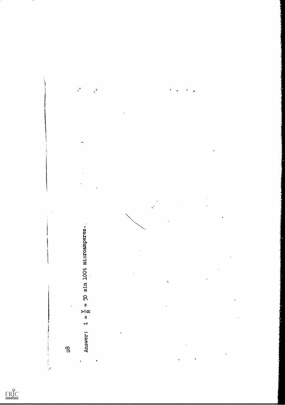
28
vAnswer:
.=
= 50 sin 100t microamperes..

a.
29
We have called thehypothetical device having a
linear v-i relationship
a resistor.
But what of the actual
physical devices,
simultaneous measurements
of whose voltage andcurrent give an uproximate
linear relationship,
at least
over a limited range
of current; what should we
call them? We call
them resistors
also, but whenever thereis the possibility of
confusion, we qualifythe name by
the adjective physical.
Thus, a
is an actualelec-
t
trical device and a
is a hypothetical
device
having a
voltage-current relationship.
30
battery
Answer:
physical resistor
ideal resistor
linear
external
network
Fig.
3
This concludes the
introductory discussion
of Ohm's law.
MIO
1101
11
--Negative
current means
411e/4:712-----thebattery is being
charged!
4e//e1Slopet
= Ro
s
31
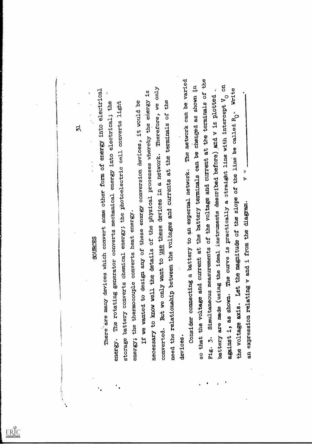
.SOURCES
There'are many devices
which convert some
other form of energyinto electrical
energy.
The rotating generator
converts mechanical energyinto electrical;
the
storage battery
converts chemical energy;
the photoelectric
cell converts
light
energy; the
thermocouple converts
heat energy.
If we wanted. to
design any of these energyconversion devices,
it would be
necessary toknaw well the details
of the physical
processes wherebythe energy is
converted.
But we only want to use
these devices in a
network.
Therefore, we only
need the relationahipbetween the voltagesand currents at
the terminalsof the
devices.
Consider connecting a
battery to an expernal
network.
The network canbe varied
so that thevoltage and current atthe batteryterminals can be
char:zed as shownin
Fig. 3.
Simultaneous measurements
of the voltage andcurrent at tbe
terminals of the
battery are made
(using the ideal instruments
described before) And V
is plotted
against 1, as shown.
The curve is practically
a Erbraightline with interceptVo on
the voltage axis.
Let the magnitude ofthe slope of the
line be called 110.
Write
an expressionrelating v and i fram
the diagram.
v
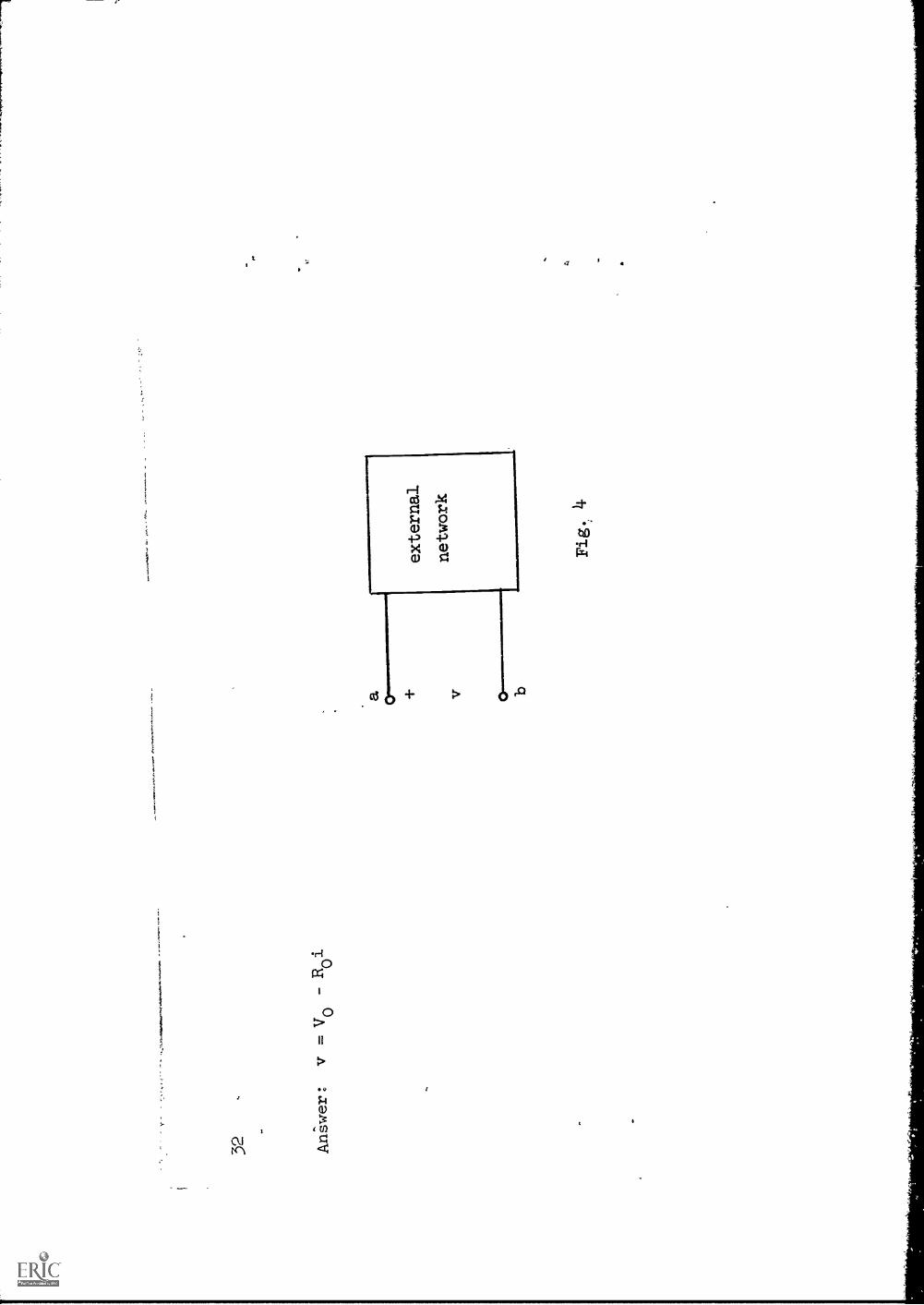
32,
Arliwer: v.V0-R0i
external
network
Fig.,4
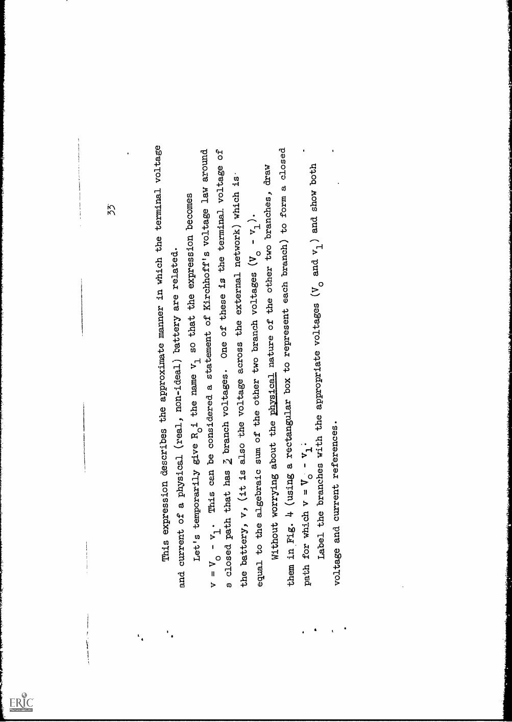
33'
This expression describes
the approximate manner
in which the terminal
voltage
and current of a physical
(real, non-ideal) battery are
related.
Let's temporarily giveRoi the name vl sothat the expressionbecomes
v = Vo - vl.
This can be considered a
statement of Kirchhoff'svoltage law around
a closed path thathas 2 branchvoltages.
One of these is
the terminal voltageof
the battery, v,
(it is also the voltage across
the external
network) which is
equal to the algebraic sumof the other two
branch voltages
(V0
-v1).
Without worrying aboutthe azgall nature
of the other two
branches, draw
them in Fig. 4
(using a rectangular box torepresent eachbranch) to form a closed
path for which v =V0 - v1;
Label the branches withthe appropriate
voltages (Voand v1) and show both
voltage and current references.

Answer:
(You may have interchanged
the vl and Voboxes, which
is OK.) But be sure your
Vo
voltage reference polarities
are correct:
)
external
network
I I

35
Since v1
= Roil the branchwith voltage v1across it
consists of a
.In the space below,
redraw the diagramto the left of
terminals a-b using anappropriate symbol
for this branchand keeping all
other
symbols.

36 Answer:
resistor
Ro
IVN
/Nr.
-1"P
lio1
a
37
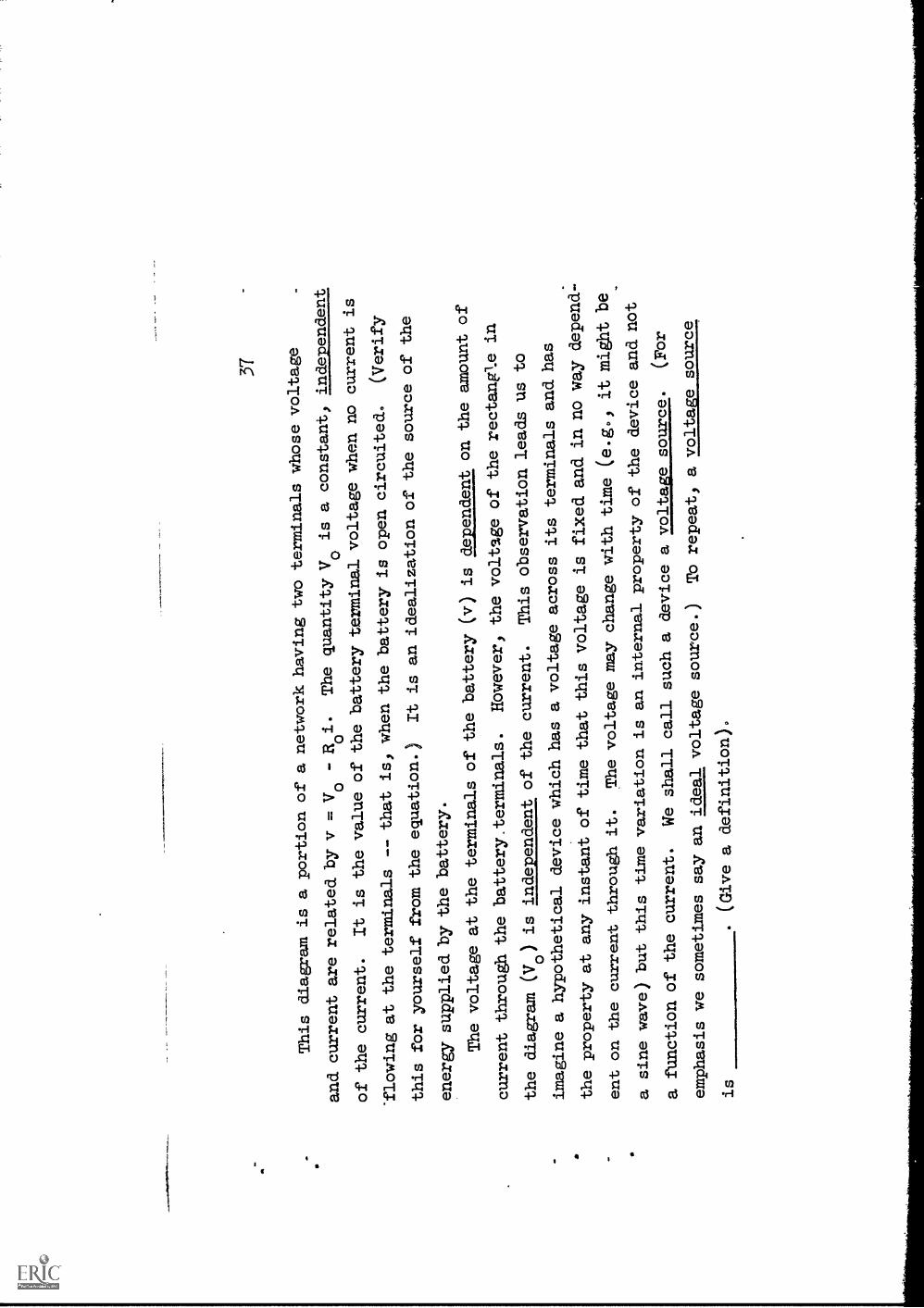
This diagram is a portionof a network having two
terminals whose voltage
and current are related by v =Vo
Roi.
The quantity Vo is a
constant, independent
of the current.
It is the value of the batteryterminal voltage when no
current is
'flowing at the terminals -- that
is, when the battery is open
circuited.
(Verify
this for yourself from the
equation.)
It is an idealization ofthe source of the
energy supplied bythe battery.
The voltage at the terminalsof the battery
(v) is dependent on the amount
of
current through the
battery.terminals.
However, the voltage of
the rectangle in
the diagram (170) is independent
of the current.
This observation leads us
to
imagine a hypothetical device which
has a voltage across its
terminals and has
the property at any instant of
time that this voltage is
fixed and in no way
depend-
ent on the current through it.
The voltage may change with
time (e.g., it niert
be
a sinewave) but this time variation is an
internal property of the
device and not
a function of the
current.
We shall call such a device a
voltage source.
(For
emphasis we sometimes say an ideal
voltage source.)
To repeat, a voltage source
is
.(Givea
definition).

38 Answer:
A voltage source is an idealized electrical
device whose terminal
volta e is inde endent of its terminal current
althou
it ma
t
depend on time.
(Note:
This definition of a voltage source is a
general one, and applies
whether
the voltage is constant or variable with
time.)
39
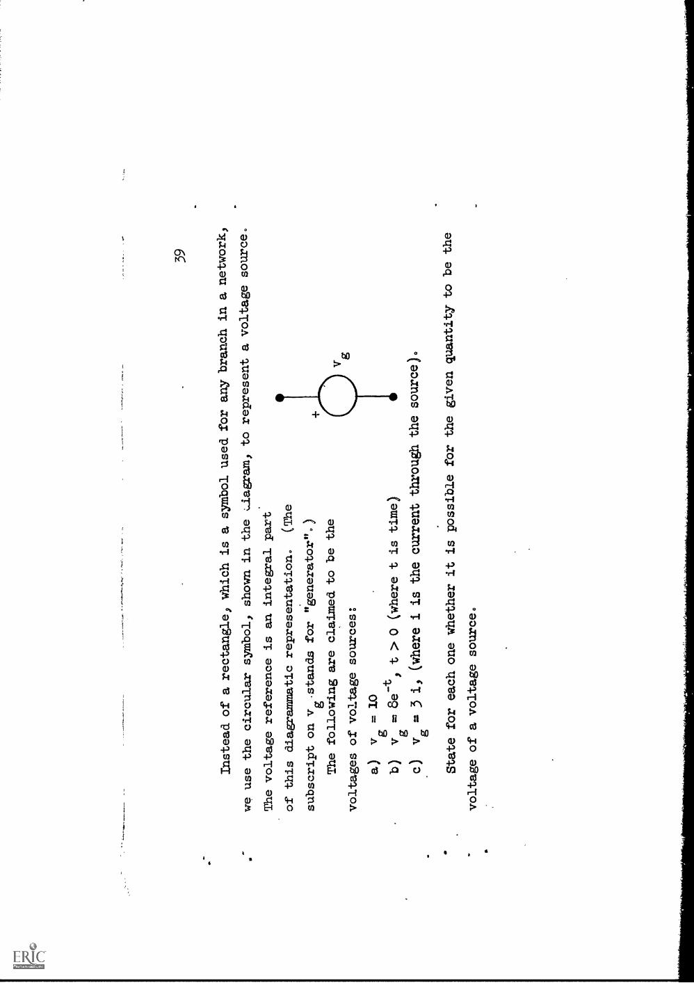
Instead of a rectangle, which is a symbol used for anybranch in a network,
we use the circular symbol, shown in the dagram,
to represent a voltage source.
The voltage reference is an integral part
of this diagrammatic representation.
(The
subscript on v .stands for "generator".)
The following are claimed to be the
voltages of voltage sources:
a)
v. 10n -t
b)
v = oe
yt > 0 (where t is time)
c)
v=
3 i,
(where i is the current through the source).
State for each one whether it is possible for the givenquantity to be the
voltage of a voltage source.

Ito
Answer:
(a)
Yes, a constant voltage
(b)
Yes, a voltage whtchvaries with time
(c)
Ho, because it depends on
its terminal current
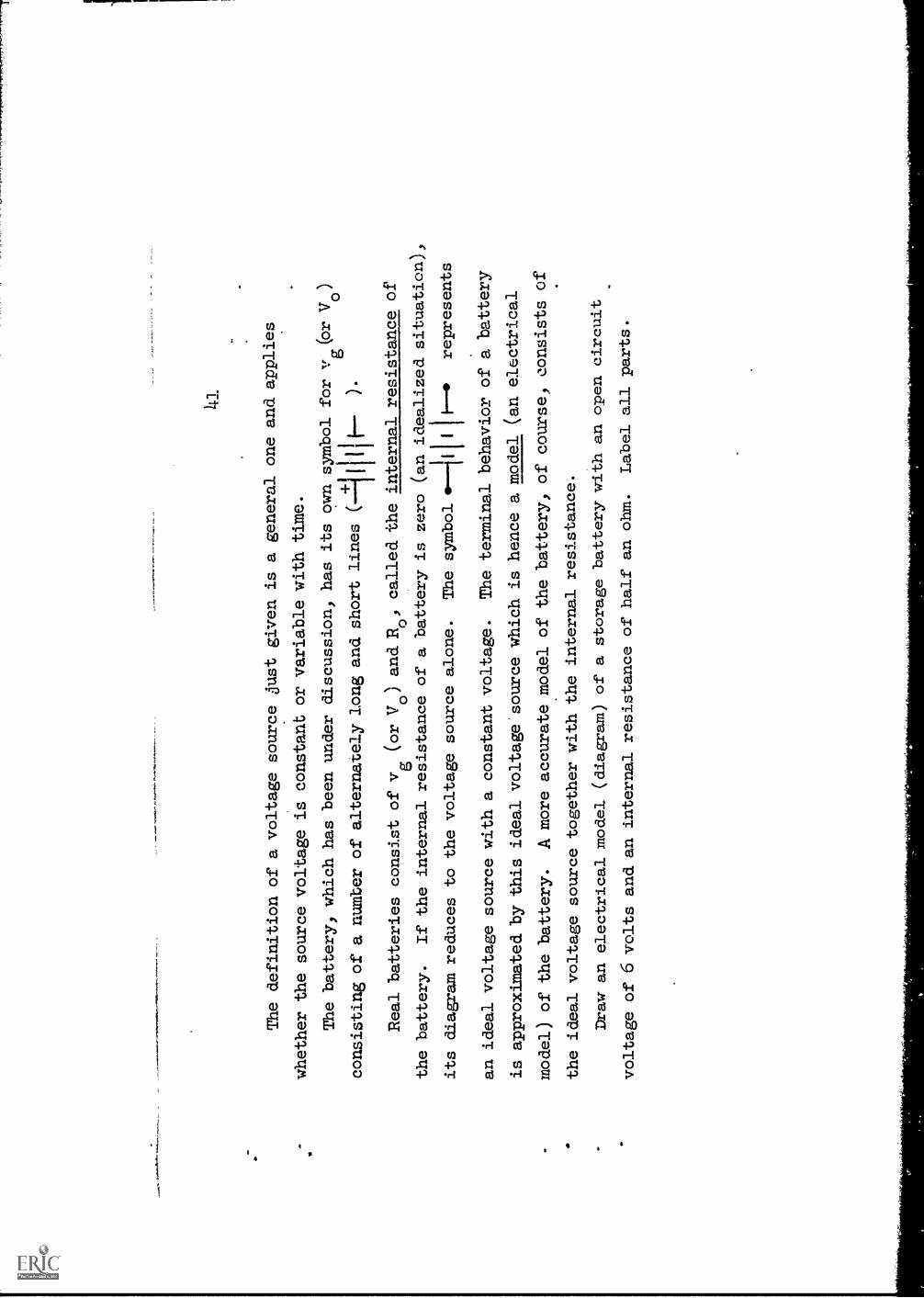
The definition of a voltage source just given is a general one andapplies
whether the source voltage is constant or variable with time.
The battery, which has been under discussion, has its own symbolfor v (or V )
go
consisting of a number of alternately long and short lines(1110--
).
Real batteries consist of v
(or Vo) and_ R0
,called the internal resistance of
gthe battery.
If the internal resistance of a battery is zero
(an idealized situation),
its diagxam reduces to the voltage source alone.
The symbol
.--11111 1* represents
an ideal voltage source with a constant
voltage.
The terminal behavior of a battery
is approximated by this ideal voltage source which is hence a model(an electrical
model) of the battery.
A more accuratemodel of the battery, of course, consists
of
the ideal voltage source together with the internal resistance.
Draw an electrical model (diagram) of a storage battery with an open
circuit
voltage of 6 volts and an internal resistance of half an ohm.
Label all parts.

o-4-4V
WIx 0 =
oa
4:6
0,
A 9 =
A
:.xarisray
+m
ra*ram,M
ieeokits...:
air
'r""'
'
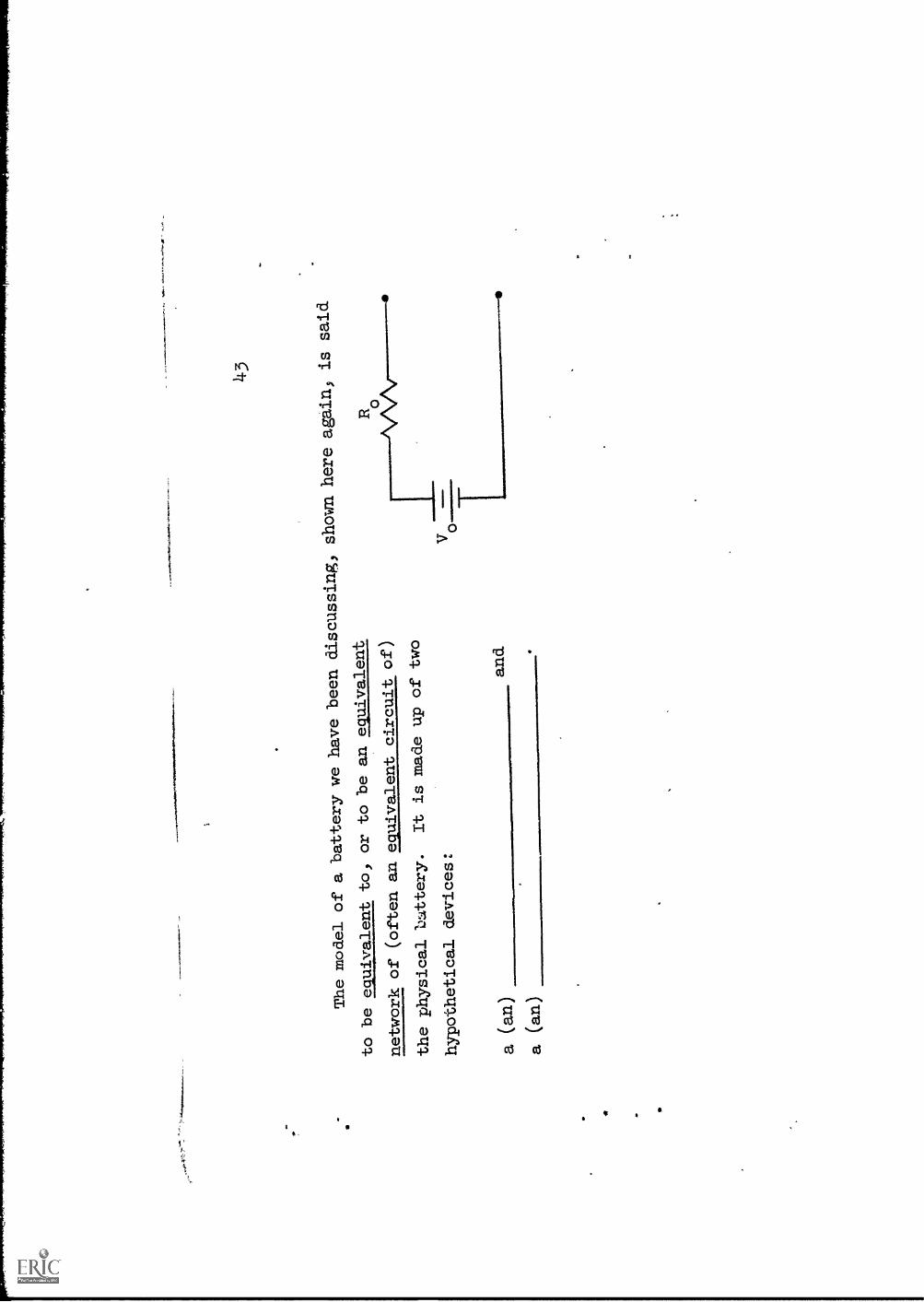
The model of a battery we
have been discussing,
to be equivalent to, orto be an equivalent
network of (often anequivalent circuit
of)
the physical b:Atery.
It is made up oftwo
hypothetical devices:
V
24-3
shown here again,
is said
a(an)
and
a(an)
414.
Answer:
voltage thource
resistor (or ideal resistor)
This moclel of a battery is equivalent to a battery because the
%.11
voltage-current relationship for the battery and for this network are
As far as behavior in a network is concerned, then, two devices are equivalent
if
46
Answer:
the terminal voltage-current relationships of the two devices
are identical.. As faxas 'file total network is concerned, the
two equivalent devices act the same.

47
To be moreprecise, a device
and its
"model" are equivalent
only over the
range ofcurrent and voltagemeasured.
The combination
of an idealvoltage source
Voand an internal
resistance Ro
will have thevoltage-current
relat.onship
v =V
-R0 ifor anyvalue of currentand will retainthis relationshipno matter
0how long it is
used.
You may have hadenough experiencewith real batteries
(flashlights, radios,
etc.) to know whether or
not this is true
of real batteries.
Does a physical
battery behave like
its model?
Give reasons for
your answer.
Answer:
NO, it will not.
First, the equivalence can only apply over the
range we have measured; for different currents the curve may depart
from a straight line.
Secondly, in a physical battery a finite
amount of chemical energy is stored.
The battery can convert only
as much as was initially stored.
Eventually it will be exhausted.
But even before this happens, it will deteriorate and the value of
its open circuit voltage will decrease and its internal resistance
will increase.
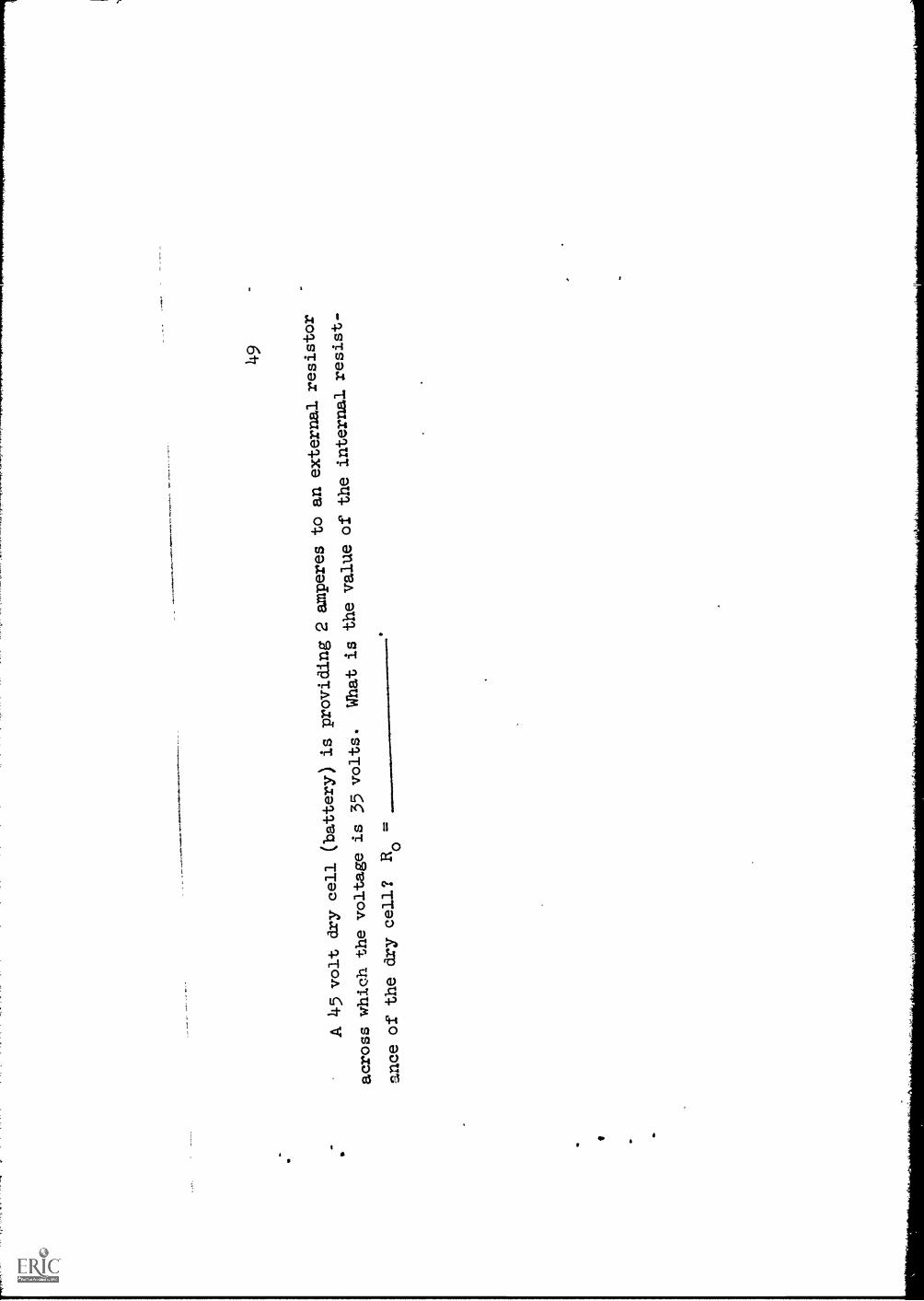
49
A 45 volt dry
cell (battery)
is providing
2 amperes
to an externalresistor
across which
the voltage
is 35 volts.
What is thevalue of the
internal resist-
ance of the drycell? Ro =
50
Answer:
Ro
= 5 ohms
(Voltage across internal resistance is 45 - 35 = 10
volts; hencp)
by Ohm's law, R0 = 10/2 = 5ohms.)
51
The modelof a batteryunder discussionwasarrived at frommeasurements
of terminalvoltage andcurrent.
The voltage was
plotted as
ordinate with cur-
rent as the
abscissa.
It is, of
course,
possible to
interchange these
and plot
i against v, as
shown in Fig.
5.
This is the same
as theprevious plotwith the
axes
interchanged.
The slope ofthe line is nownegative andequal to
1/ao
in
magnitude.
Suppose the
line is extended
to
intercept the
i axis at
the value 10:
From the
diagram writethe equation
relating v andi, this timewith i
taken as the
dependent variable.
Io
'Slope'
.7..itz
Fig. 5

52 Ans
wer
:=
I-
vo
Ro

52(a)
Draw an equivalent circuit
for a physical batteryand identify thebranches
by name and symbol.
Draw the v-i plot for the
equivalent circuit andidentify the two
intercepts
by symbol and name
(using terms such as SHORT CIRCUIT andOPEN CIRCUIT)-
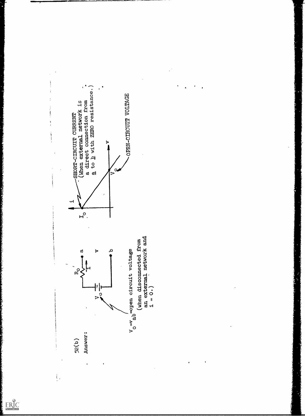
52(b
)Answer:
rAr-
ro--
--
a b
Vo=vab=open circuit voltage
(when disconnected from
an external
network and
i = O.)
SHORT-CIRCUIT CURRENT
(When external network
is
a direct
connection from
a to b withZERO
resistance.)
11'\--OPEN-CIRCUITVOLTAGE
53
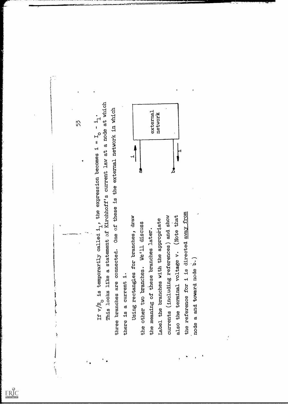
If v/Ro
is temporarily called i1,
the expression becomes
i10
This looks like a statement of
Kirchhoff's current law at anode at which
three branches are connected.
One of these is theexternal network in which
there is a current i.
Using rectangles for branches;
draw
the other two branches.
We'll discuss
the meaning of
these branches later.
Label the branches with theappropriate
currents (including references)
and show
also the terminal voltage v.
(Note that
the reference for i is directed away
from
node a and toward node b.
)
external
network

,3
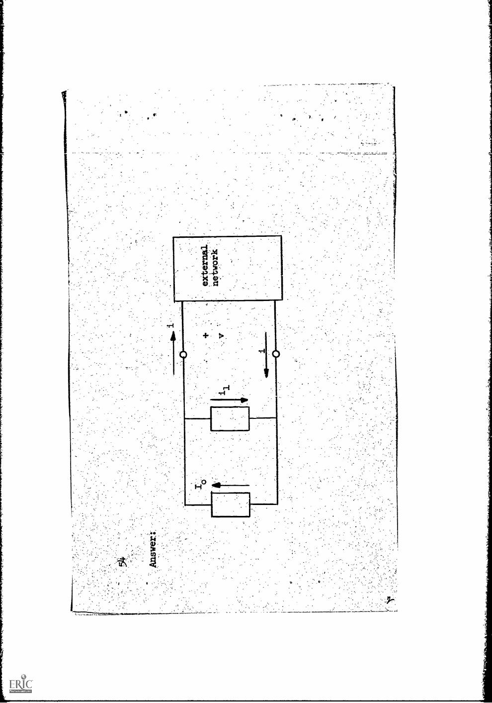
55
Since i1
= v/ilo
,in the second branch) and v is the voltage across this branch)
the
branch in which i1
is flawing must consist of a
whose value is
56
..
Answer:
resistor
Ro

57
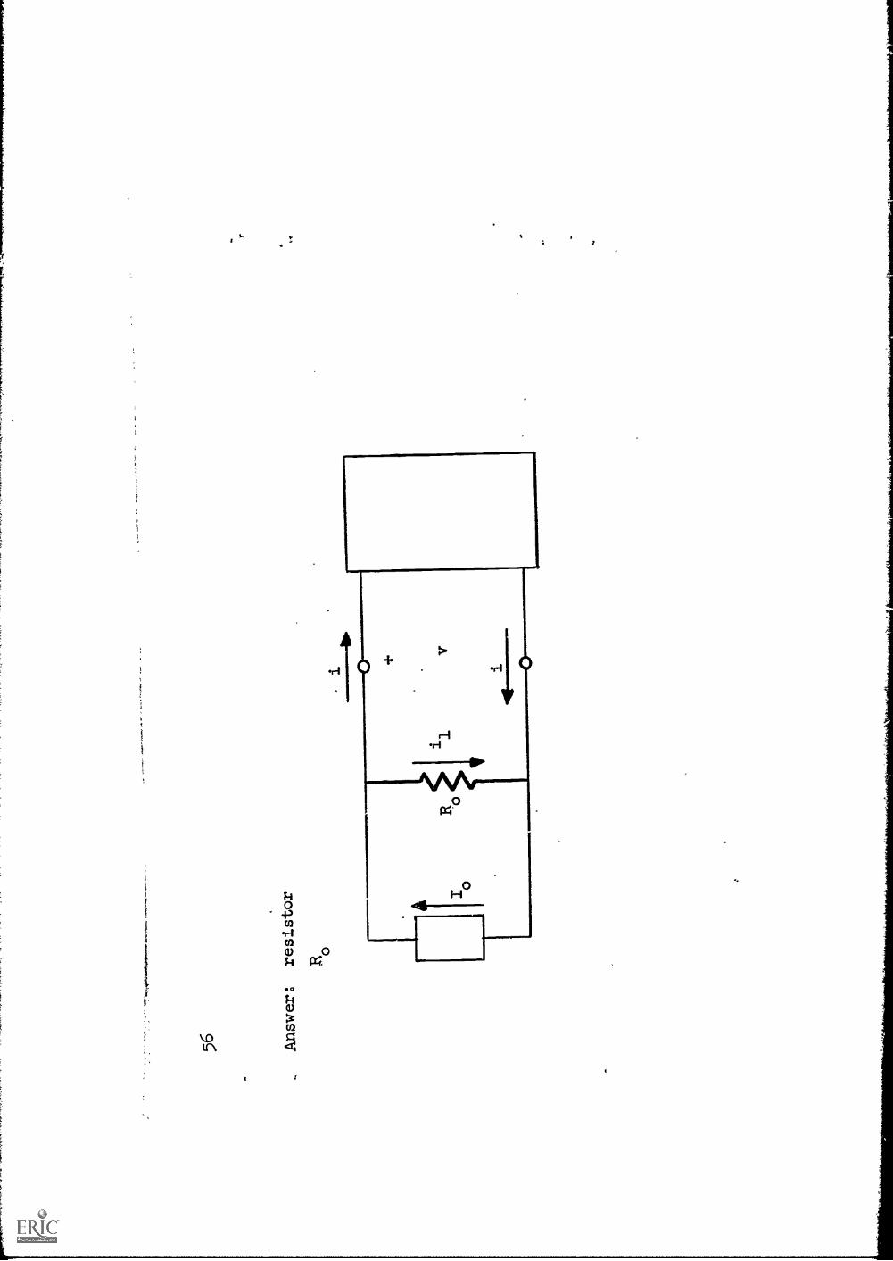
The third branch carries a constant current Iowhich is independent of the
voltage at the terminals of the battery, althougli-the terminal current of the hat-
tery is certainly dependent on the voltage.
We met an analogous situation before
when the voltage source was introduccd.
This observation leads us now to imagine a hypothetical device which has a cur-
rent in its terminals with the property that at any instant of time this current is
inde endent of the volta e across the terminals.
The current may change with time
but this variation is not dependent on the terminal voltage.
We shall call such a
device a current source (or an ideal current source, for emphasis).
It also will
be given a circular simbol to designate a source.
It can be distinguished from
a,
voltage source by means of the reference which, in this case, is an arrow either
.
alongside the symbol or inside the circle) as shown.
for generator.)
The equivalent circuit representing the battery
then takes the following form.
(Complete the
diagram and label all parts.)
(The subscript again stands
1011
. .1
OE
M a
NI I
M O
NO
ME
I.1
0 M
I= 4
0V
.MO
N0
NO
D...
. 11
110
MM
. 411
1 11
11,
01.
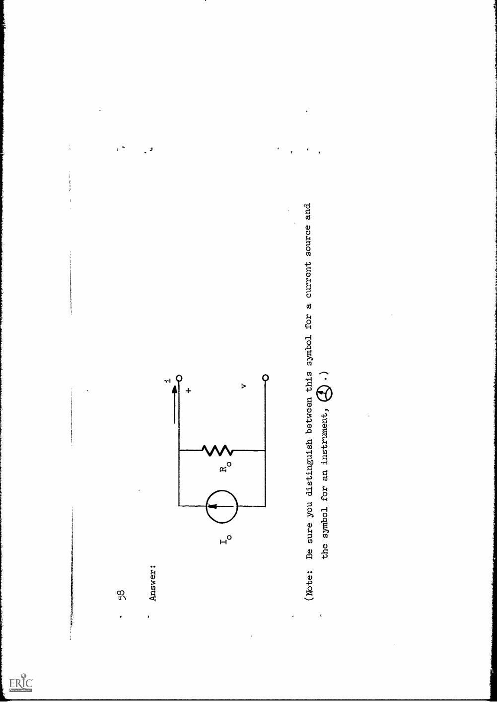
Answer:
I o
(Nbte:
Be sure you distinguish between this symbol for a current sourceand
the symbol for an instrument,

59
This diagram constitutes analternative model of a battery.
It is equivalent
to a battery because it hasthe same
Describe what you would do at
the terminals in order to
observe (or use ideal
instruments to measure) Vo
.How would you measure Io?
a)
To measure Vo
:
b)
To measure Io
:
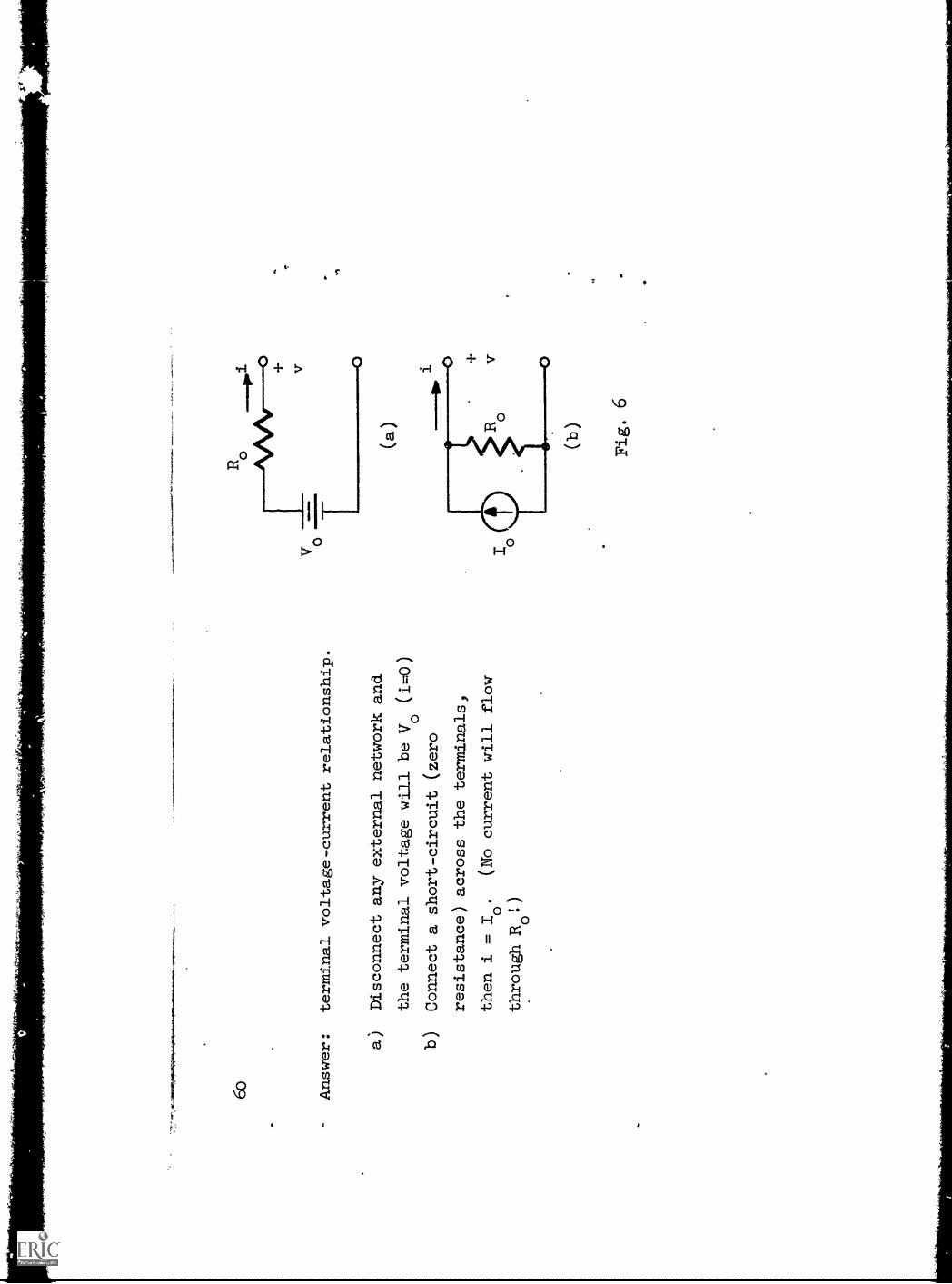
6o
-
Answer:
terminal voltage-current relationship.
a)
Disconnect any external network and
the terminal voltage will be Vo (i.0)
b)
Connect a short-circuit (zero
resistance) across the terminals)
then i
=I.
(No current will flow
through Ro!)
v o
Ro
(a
0
(b)
Fig. 6
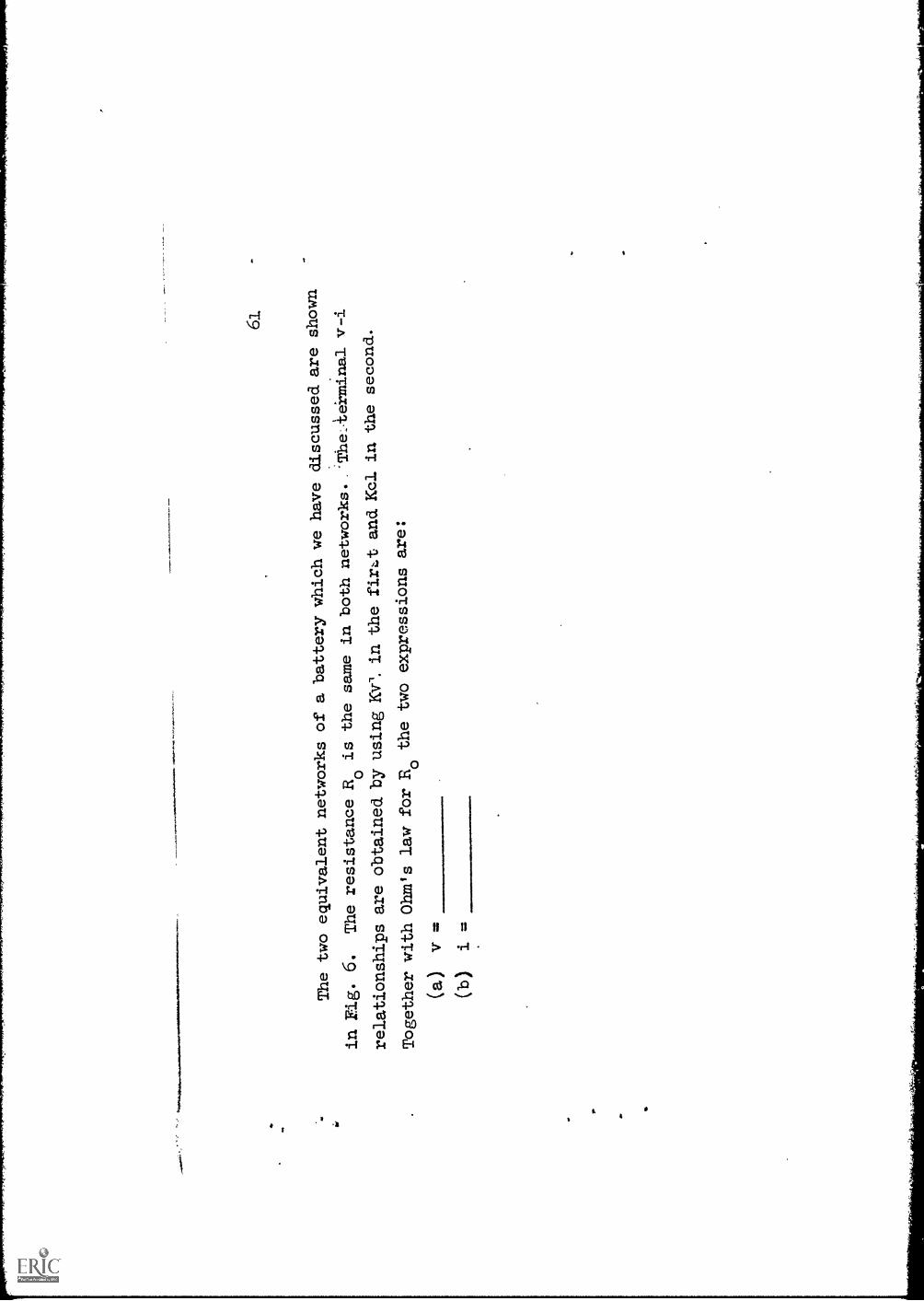
61.
The
two
equivalent networks of a
batte
ry w
hich
we
ilaV
edi
scus
sed
are
show
n
in F
ig. 6
.T
he r
esis
tanc
e It
o is
the same in. both networks
'The.k,e'rmi.nal v-i
rela
tions
hips
are
obt
aine
d bY
usin
g K
Y'.
in th
e fi
rtand Kc2. in the second.
Tog
ethe
r w
ith O
hm's
law
for
Bo
the
two
expr
essi
ons
are:
(a)
1'3
____
____
_(b
)i.
="*
.

62 Ans
wer
:v
= V
oR
oi
41,

The
sec
ond.
of
thes
e ca
n be
sol
ved.
for
v.
The
res
ult i
s v
=
63
611. Ans
wer
:v
=R
I -R
i or
R (
I .-
i)0
00
00
65
This is to be compared with v = Vo
Roi.
Since the two networks are
both equivalent to a battery, they should be equivalent to each other.
This
means they should have the same terminal v-i relationship.
Comparing the two
expressions leads to the conclusion that equivalence requires 1/0
or I
=0
6 6
Ans
wer
:V
= R
I0
0 0
Vo
I=
oR
o
Fig.
7

67
'mp
This conclusion is
consistent with theoriginal v-i curve
of the battery
4(extended to intercept the i axis as
shown in Fig.
7) fram which it is
clear
that the ratio of Vo
to Io
is the
(negative) slope Ro
.
It has alreadybeen noted that Vo
is theterminal voltage on open
circuit,
that isj when nothingis connected to
the terminals.
Similarly, from the
equivalent network it canbe seen that 10
is the terminal
current when
Alp
.,
68
Answer:
...
when there is a short circuit, that is when
the terminals are
connected dire.ctly together.
Remark In the case of a physical battery, it is
inadVisabie to short circuit it)
since the battery will then "run down" rapidly.
However, as far as themodel
is concerned, short circuiting the
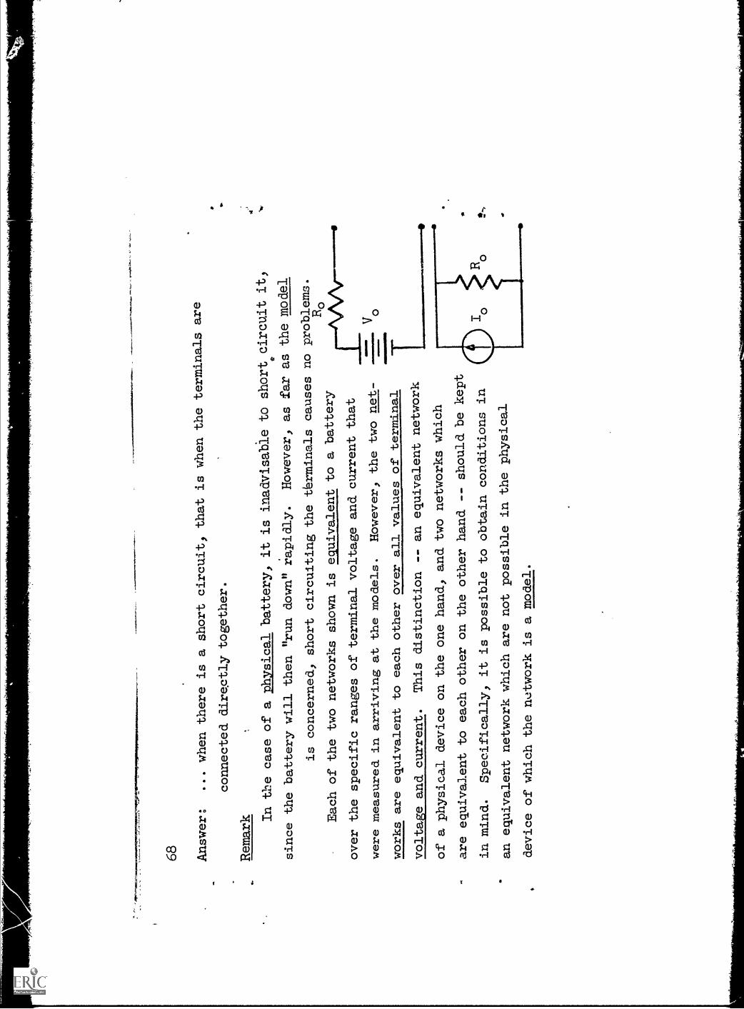
tbrminals causes no problems.
Ro
Each of the two networks shown is equivalent to a battery
over the specific ranges of terminal voltage andcurrent that
were measured in arriving at the models.
However, the two net-
works are equivalent to each other over all values of terminal
MIO
NO
INV
aw 1--
voltage and current.
This distinction -- an equivalent network
of a physical device on the one hand, and two networks
which
are equivalent to each other on the other hand --
should be kept
in mind.
Specifically, it is possible to obtain conditions in
an equivalent network which are not possible in
the physical
device of which the network is a model.

in the two equivalent
networks of the battery wehave been discussing,
three quantities appear inboth networks.
Name these and. write their
mathematical symbols.
1. 2. 3.
Symbols
Name
Description
-
69
70
Answer:
(a)
the internal resistance-Ro
(b)
the open circuit voltage -Vo
(c)
the short-circuit
current -
o
'4
71
These three quantities are related.
If two of them are known the third
one can be calculated.
Which two?
Give an expression for finding the third.
72 Answer:
Any two.
The relationship among them is Vo = RoIo.
.001
0111
:7f.'
,.....
dera
ltelO
WIN
II.em
omr
73
a
To sum up, we have defined two ideal
devices which are 'sources
of electric
energy: (a)
(ID
)
's
711-
Ans
wer
:(a
)a
volta
ge s
ourc
e(b
)a
curr
ent s
ourc
e
75
a 3:
By exaiining the voltage-currentrelationship at
;the
term
inal
S,of
aba
ttery
, ,
we have found two
netwOrks which are eggivalent
td the battery, bywhich is
meant ths.,t
Draw the two equivalent circuits
of a battery and. thev-i plot which is
applicable to both circuits.
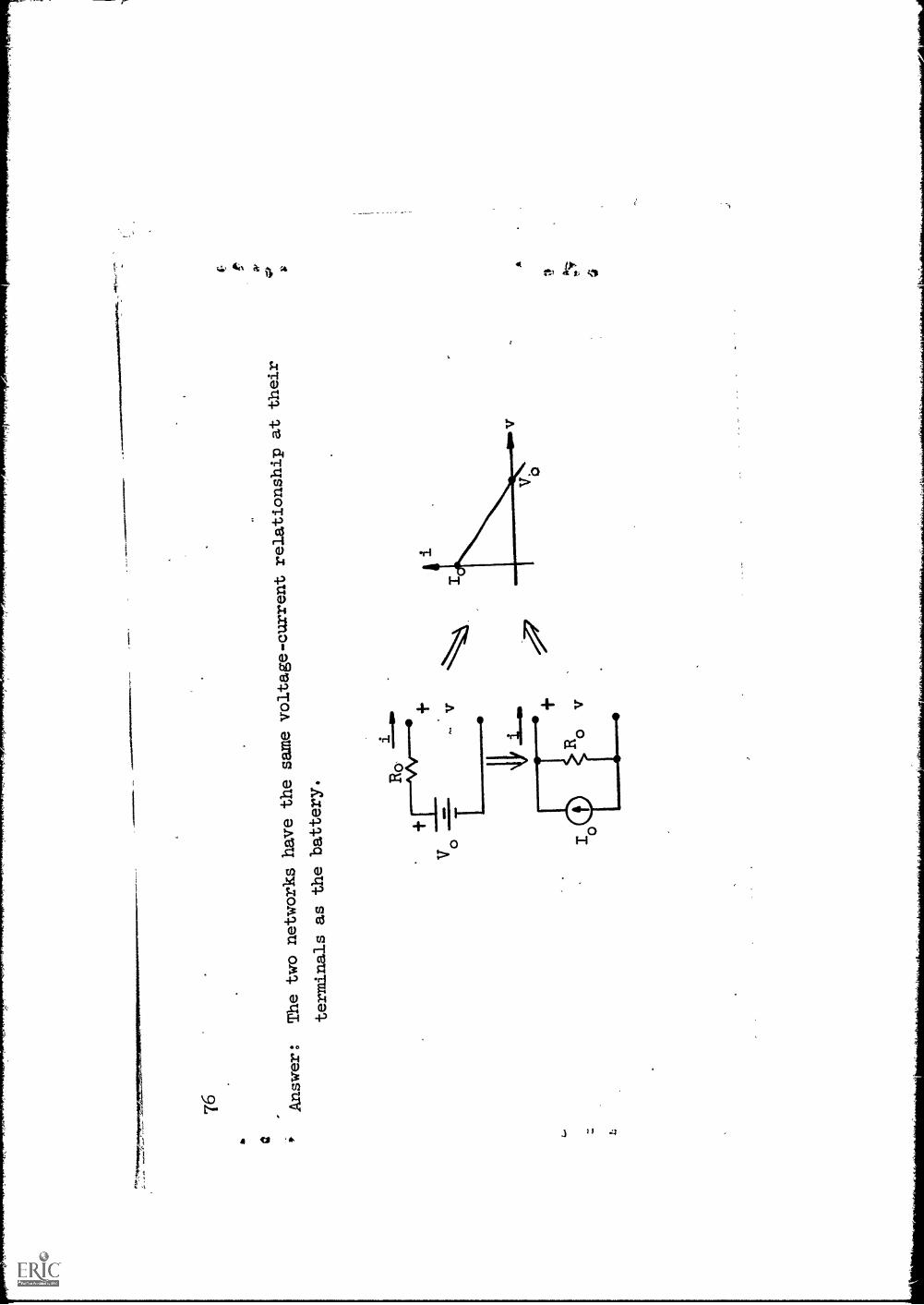
a
76 Answer:
The two networks
have the same
voltage-current
relationship at
their
terminals as the
battery.
77
The voltage source in one of thesetwo networks and the current source
in the other are constants.
Is the following statement true?
If it is not, then correct
it.
However, a Current source need not
have a constant current nor a
voltage
source a constant voltage; they can vary
with time.
4

78 Answer:
Yes, it is true.
Either can be a
constant or time varying.
This terminates the section on sources.