Embed Size (px)
Citation preview

MELBURY HE
3800 TO 10000
Document No. 410821-V11 / 18.12.2020
FR DE EN ES IT NL
Installation, use and
maintenance instructions
CAUROIR SITE Route de Solesmes
FR - 59400 CAUROIR
L

MELBURY HE 3800-10000 - Installation, Use and Maintenance
Page 2 / 36 410821-V11

MELBURY HE 3800-10000 - Installation, Use and Maintenance
10.12.2019 Page 3 / 36
WARNINGS AND CONFORMITIES
Symbols used in this document
INFORMATION: This symbol highlights the remarks.
CAUTION: Failure to follow these guidelines carries the risk of damage to the facility or to other objects.
DANGER: Failure to follow these instructions can cause injury and serious property damage.
Conformity
This boiler fulfils the requirements of the low voltage directive 73/23/EEC, of the EMC-directive 89/336/EEC and the efficiency directive 92/42/EEC. The boiler range with ECA-rating has efficiencies in conformity with the requirements of the Enhanced Capital Allowance Scheme (ECA).
CE-certificate: CE 0461 Type marking: 01-226-598 X
Environmental compatibility
This device contains electrical and electronic elements and should not be discarded in household waste. Local regulations in force must be observed.
Steps to be taken in case of danger Close fuel supply disconnect unit from mains using
emergency stop or main switch (outside of the boiler room).
Use suitable fire extinguishers to extinguish flames.
Occurrence of gas smell (gas units) - Ventilate the affected rooms thoroughly by opening doors and windows.
- Do not use any electronic devices (mobile phone, etc.). - Do not activate any electrical contacts (light, motor,
lift, doorbell, etc.) - Do not ignite matches or lighters, and do not smoke.
- Call the gas board or heating engineer.
The boiler The boiler room must be lockable and it's external air
openings must conform to the norms prevailing locally. When in doubt regarding air circulation, measure the CO2 count with the burner operating at its maximum delivery and the room ventilated only by the burner ventilation air openings and a second time with the door open. The CO2 count measured in both cases must not differ. Should there be more than one unit in the same room, this test must be performed with all the equipment operating simultaneously.
Never obstruct the boiler room's air openings, the burner fan suction opening, and any air ducts and
ventilation. The equipment must always be protected against
rain, snow, and freezing conditions. The boiler room must be kept clean and free of
volatile substances that may be sucked into the fan and clog the inner burner or combustion head air ducts.
The combustion air must be free of halogens (chlorine and fluorine compounds). If there is any doubt, the quality of the combustion air must be ensured with an external air intake.
!
STOP

MELBURY HE 3800-10000 - Installation, Use and Maintenance
Page 4 / 36 410821-V11
Packaging After removing all packaging materials, check the
contents to make sure that no damage has occurred during shipping. When in doubt, do not use the
Unit Smooth boiler performance and manufacturer’s
guarantee are dependent upon adherence to the boiler installation, operation and maintenance instructions contained in this booklet.
Never permit children or unauthorized persons to tamper with the equipment.
The unit must be used only for its expressed application. All other uses are considered dangerous.
The burner's minimum and maximum delivery settings, all pressures and temperatures must all be contained in the range stipulated in this manual.
Modification of the equipment in order to alter its performance or applications prohibited.
Do not open or tamper with components of the unit other than those parts of the unit that are subject to maintenance operations.
apparatus and contact the supplier. The packaging materials are to be disposed of properly.
Never touch the hot parts of the unit; these parts (flue gas conduit, sight glass, burner parts, etc) may remain hot for quite some time after the burner has switched off.
Never touch the unit with wet parts of the body or without wearing shoes.
When the unit is not to be used for a longer period, the main power switch on the electrical control panel must be switched off and the manual valve on the unit fuel supply line must be closed.
The device contains components made of synthetic silicon mineral fibers (ceramic and glass fibers, insulation wool). These components must be disposed of appropriately at the end of their life cycle. Local regulations must be observed.
Installation and settings
The installation and calibration of the unit must be performed exclusively by qualified personnel in conformity with existing regulations and the indications provided in this Manual.
INFORMATION:
For hot water installation: o Maximal operating temperature: 95°C when the boiler is managed by a
Navistem B1000 ou B2000. o Maximal operating temperature: 105°C if the regulation system is compatible
with this work. In any case, this device has been designed according to EN 14394. The safety limit thermostat does not exceed 110 °C.
Fuel The unit must be fed with the type of fuel for which it
has been preset as indicated on the rating plate. The fuel pressure must be according to the values
listed in the burner manual. The fuel line that feeds the unit must be sized
according to the requirements of local regulations and the prescriptions in the burner manual. The line must be perfectly sealed. The fuel supply line must also be equipped with all the control and safety mechanisms required by local regulations in force. The line must be free from all impurities; take particular care that foreign matter does not enter the line during installation.
Oil: - The light oil storage tank must be adequately
protected against penetration of impurities and water. The fuel tank must be kept full of fuel during the summer in order to avoid the condensation of humidity. Clean the tank carefully before filling. Beware not to overfill the tank.
- Both the tank and the unit fuel supply line must be protected from frost.
- Oil consumption and tank unit must be checked regularly, in order for leaks to be detected in good time.
Gas: - The gas line must be checked for leakage during
commissioning and after each disconnection.

MELBURY HE 3800-10000 - Installation, Use and Maintenance
10.12.2019 Page 5 / 36
Water quality The following rules apply once the boiler is put into service and remain valid until the end of life of the product.
Preparing the water system before putting the boiler into service For any installation (new or renovation), the water system pipes must be thoroughly cleaned. The purpose of this initial cleaning is to eliminate germs and residue that can cause deposits to form. In new installations in particular, residue from grease, oxidised metal, and even copper microdeposits must be removed. In renovated installations, cleaning should focus on removing sludge and the products of corrosion formed when the unit was last in operation. There are two types of methods for cleaning and
removing sludge: a high intensity approach that takes a few hours and a slower, more gradual approach that takes several weeks. This first type of cleaning must be done before connecting the new boiler, and with the second type, a filter should be installed on the back of the boiler to capture loosened deposits.
The cleaning performed prior to installation improves performance, reduces energy consumption, and resists scaling and corrosion on the unit. A professional (water treatment) should carry out the cleaning.
Protecting the unit against scaling Water naturally contains dissolved calcium ions and carbonates that cause scaling (calcium carbonate) to form. To prevent excessive deposits, take precautions with regard to the water used to fill the unit: TH < 10°f
Water must be added during the life of the boiler. The new water adds scaling to the water system. The amount of fill water plus the amount of make-up water added during the life of the unit should not be more than three times the water capacity of the heating system. Also, the hardness of the make-up water must be controlled. Make-up water: TH < 5 °f
Adding a large amount of untreated water always contributes a significant amount of scaling. To monitor this and to detect problems, a system water meter must be installed. Failure to comply with these guidelines (such that the fill water plus the make-up water is more than three times the water capacity of the heating system) requires a full cleaning (to remove sludge and scaling) to be performed.
Additional precautions are required for operation:
- When the unit has a water softener, the equipment must be inspected on a regular basis in order to ensure that it is not outputting chloride-rich water into the system. The concentration of chlorides must always remain below 50 mg/l.
- To prevent the build-up of calcium deposits (such as on exchange surfaces), the unit should be brought into service slowly, starting by operating at a low power with high primary water flow.
- When the tap water lacks the desired qualities, water treatment is required. The fill water must be treated, and whenever new water is added, the make-up water must also be treated.
- Installations with multiple boilers require all of the boilers to be brought up simultaneously at minimal power. Doing this prevents the calcium in the water from depositing on the exchange surfaces of the first boiler.
- When working on the unit, avoid draining it completely; only the required parts of the system are to be drained.
The rules listed above are designed to minimise scaling on the exchange surfaces and thus to increase the life of the boilers. To optimise how the equipment operates, plan to remove its calcium deposits. This must be done by a specialized company. Also, before putting the unit into service, verify that the heating system is not damaged (ex. leaks). If it has excessive scaling, the unit's settings for operation and for water treatment must be adjusted.
Protecting steel and stainless-steel boilers against corrosion Corrosion can affect the iron components used in boilers and heating systems, which is directly related to the presence of oxygen in the water heater's water. Dissolved oxygen that enters the unit when it is being filled for the first time reacts with the equipment materials and quickly disappears. Without refreshing the oxygen through significant contributions of water, the unit might not experience any damage whatsoever.
However, it is important to follow the sizing rules and installation guidelines in order to prevent oxygen from continuously flowing into the heating water. From these rules, we have:
- Preferably an expansion vessel with a membrane rather than an open expansion vessel that allows direct passage.

MELBURY HE 3800-10000 - Installation, Use and Maintenance
Page 6 / 36 410821-V11
- Internal pressure with the unit of more than 1 bar cold.
- Remove leaky (permeable) components that are letting out more gas than as if they were sealed.
If the guidelines above are followed, the unit's system water has the proper characteristics to last a long time: 8.2 < pH < 9.5 with a water concentration of < 0.1 mg/l.
If there is a chance that oxygen could enter the unit, you must take additional precautions. Adding an oxygen scavenger (ex. sodium sulphite) is highly recommended. We recommend directing any water
treatment questions to specialists, which can provide:
- The appropriate treatment based on the characteristics of the unit,
- A monitoring agreement with a guarantee as to the results.
For units in which the water comes into contact with heterogeneous materials, such as copper or aluminum, appropriate treatment is recommended in order to ensure that the unit will last. In most cases, this consists of adding corrosion inhibitors (in the form of chemical solutions) to the unit. Referring to a water treatment specialist is recommended.
Setting up a filtration system A filtration system on the back of the boiler is recommended in order to remove suspended particles
Choice of burner / boiler
from the unit.
We recommend adopting modulating burners to avoid thermal shock in operation.
Hydraulic Set up an effective degasser as close as possible to the boiler outlet to evacuate the air from the networks introduced during the filling and the addition of water in order to maintain a good convection coefficient. Add an additional expansion vessel if the characteris-
tics of the pressure maintenance unit do not allow the pressure variations to be limited to 0.5 bar in order to limit the variations in hydraulic pressure. Respect the minimum flow rates recommended. (chapter 2.5.1. - 2.5.2.)
Unit monitoring If the recommendations listed above (new installation or renovation) have been followed, the unit monitoring is limited to:
- Checking the amount of make-up water (fill water volume + make-up water volume < 3 times the unit volume)
- Checking the pH level (stable or slightly increasing) - Checking the total hardness (stable or slightly
decreasing)
We recommend monitoring these parameters two to three times a year. Note: Monitoring the quantity of make-up water is critical to the long life of the unit. If any of these parameters deviates from the above recommendations, refer to a water treatment specialist to correct the problem.
Setting up a plate exchanger If the recommendations listed above cannot be met, you can set up a plate exchanger to separate the primary
system from the secondary system, which protects the boiler from undesirable effects.
Exploitation The frequency of cold starts should be as low as possible; during these periods, the flue gas temperature can be low and cause condensation that is detrimental to the life of the boiler; it is recommended not to exceed a cold start per week.
During a cold start, the heat emitters of the installation will be irrigated when the set temperature is reached; the temperature rise of the installation will be carried out at minimum power.
Do not shut off the burner at full load to avoid temperature shock.
Do not hesitate to add buffer volumes to the plant's hydraulic system to avoid short operating cycles, especially when the boiler is protected by an isolation plate heat exchanger. Regarding the regulation of the installation, we recommend burner modulation parameters (PID) sufficiently slow to ensure stability and low temperature variations, start / stop differentials / hysteresis must be reasonable in order to leave a range of operation sufficient for the burner and to ensure its modulation (value +/- 4 ° C). All strategies must allow the burner to be started up for an average operating time of 30 minutes.
The temperature variations of the boiler must be as low

MELBURY HE 3800-10000 - Installation, Use and Maintenance
10.12.2019 Page 7 / 36
as possible to ensure the highest service life.
The first heating must allow the evacuation of moisture from concrete doors, it is necessary to avoid any heat shock and adopt a rise in temperature as slow as
possible.
Do not hesitate to adopt the burner's burner maintenance accessories to minimize structural vibration of the burner assembly.
Unit monitoring If the recommendations listed above (new installation or renovation) have been followed, the unit monitoring is limited to: - Checking the amount of make-up water (fill water volume + make-up water volume < 3 times the unit volume) - Checking the pH level (stable or slightly increasing) - Checking the total hardness (stable or slightly
decreasing) We recommend monitoring these parameters two to three times a year. Note: Monitoring the quantity of make-up water is critical to the long life of the unit. If any of these parameters deviates from the above recommendations, refer to a water treatment specialist to correct the problem.
Setting up a plate exchanger If the recommendations listed above cannot be met, you can set up a plate exchanger to separate the primary system from the secondary system, which protects the
Electrical installation Electrical connections must be made exclusively by
qualified personnel and all prevailing electrical regulations must be scrupulously observed.
Make sure that the electrical power supply used for connection conforms to the specifications indicated on the rating plate and in this manual.
The unit must be correctly connected to an efficient ground system in conformity to the prevailing norms and checked and controlled for efficiency by qualified personnel when in doubt.
Never confuse neutral wires with phase wires. The unit must be hooked up to the electrical network
with a plug-socket connection that is such as to
boiler from undesirable effects.
prevent inversion of phase and neutral. Install a master switch for the heating plant as requested by existing legislation.
The entire electrical system, and all cable sections in particular, must be adequate to deliver the maximum absorbed power value indicated on the equipment's rating plate and in this manual.
If the mains power cable is found to be defective, it must be replaced only by qualified personnel.
Never stretch power supply cables and keep them well away from sources of heat.
Maintenance Maintenance must be performed by qualified
personnel regularly or at least once a year. Prior to performing any maintenance operations,
switch off the power supply by using the main switch and cut off the fuel supply as well.
Only parts indicated by the manufacturer in the Spare Parts Catalogue may be replaced.
In order to avoid all types of health hazards, suitable clothing and a protective mask must be worn for work on or with components made of synthetic silicon mineral fibers (ceramic and glass fibers, insulation wool).
Malfunction If the unit stops working and goes into lock-out and
does not resume operation after two or three manual lock-out reset attempts, disconnect the power supply, do not attempt to repair, and contact a qualified specialist.
All repairs required must be performed exclusively at a technical servicing and/or technician centre
authorized by the manufacturer using original spare parts only. Failure to observe the above may compromise the reliability and safety of the equipment.
Any failure or damage resulting from improper use or intentional damage will relieve the manufacturer from any guarantee obligation.

MELBURY HE 3800-10000 - Installation, Use and Maintenance
Page 8 / 36 410821-V11
CONTENTS
WARNINGS AND CONFORMITIES................................................................................ 3 Symbols used in this document ............................................................................................................................. 3 Conformity ............................................................................................................................................................. 3 Environmental compatibility ................................................................................................................................... 3 Steps to be taken in case of danger ...................................................................................................................... 3 The boiler ............................................................................................................................................................... 3 Packaging .............................................................................................................................................................. 4 Unit ........................................................................................................................................................................ 4 Installation and settings ......................................................................................................................................... 4 Fuel ........................................................................................................................................................................ 4 Water quality .......................................................................................................................................................... 5 Electrical installation .............................................................................................................................................. 7 Maintenance .......................................................................................................................................................... 7 Malfunction ............................................................................................................................................................ 7
1. DESCRIPTION ...................................................................................................... 10 1.1. General information ...................................................................................................................................... 10 1.2. Scope of supply ............................................................................................................................................ 10
2. DATA ................................................................................................................................................. 11 2.1. Main data ...................................................................................................................................................... 11 2.2. Minimum operating pressure ........................................................................................................................ 11 2.3. Dimensions Melbury HE ............................................................................................................................... 12 2.4. Dimensions of custom-made models for Melbury HE .................................................................................. 14 2.5. Technical data Melbury HE ........................................................................................................................... 16 2.6. Correction values for different operating conditions ..................................................................................... 20
3. BOILER CONTROL PANEL ......................................................................................... 21 3.1. Description .................................................................................................................................................... 21 3.2. Basic equipment NAVISTEM B1000 and B2000 ......................................................................................... 21 3.3. Additional equipment .................................................................................................................................... 21 3.4. Heating regulators ........................................................................................................................................ 22 3.5. Burner cables ............................................................................................................................................... 22
4. INSTALLATION GUIDE .......................................................................................... 23 4.1. Boiler room and boiler room ventilation ........................................................................................................ 23 4.2. Planning dimensions .................................................................................................................................... 23 4.3. Hydraulic connection .................................................................................................................................... 25 4.4. Electrical installation ..................................................................................................................................... 25 4.5. Turbulators ................................................................................................................................................... 26 4.6. Connecting the burner .................................................................................................................................. 27 4.7. Flue gas system ........................................................................................................................................... 29

MELBURY HE 3800-10000 - Installation, Use and Maintenance
10.12.2019 Page 9 / 36
5. OPERATING CONDITIONS .................................................................................... 30 5.1. Fuels ............................................................................................................................................................. 30 5.2. Combustion air ............................................................................................................................................. 30 5.3. Filling the installation and water quality ........................................................................................................ 30 5.4. Protection against corrosion ......................................................................................................................... 30 5.5. Requirements for operation .......................................................................................................................... 30
6. OPERATION ............................................................................................................. 31 6.1. Commission .................................................................................................................................................. 31 6.2. Decommission .............................................................................................................................................. 31 6.3. First steps to take in case of failure .............................................................................................................. 32
7. MAINTENANCE .................................................................................................... 33 7.1. Periodical checks and maintenance operations ........................................................................................... 33 7.2. Boiler cleaning .............................................................................................................................................. 33 7.3. Burner maintenance ..................................................................................................................................... 33
8. SPARE PARTS ............................................................................................................. 33

MELBURY HE 3800-10000 - Installation, Use and Maintenance
Page 10 / 36 410821-V11
1. DESCRIPTION
1.1. General information Melbury HE boilers are high efficiency, power-saving boilers ranging from 1150 to 5400 kW, from 1000 to 4700 kW for low-NOx applications and from 1000 to 4300 kW with ECA-rating. They can be operated in
combination with oil or gas burners. Models Melbury 3800-10000 are also adapted for use with heavy fuel at a maximum output corresponding to the low-NOx applications.
The Melbury HE boiler range are three pass, smoke tube boilers with combustion chamber and flue way using the low-Nox technology. The geometry of the furnace, the furnace’s low charge, coupled with the Ygnis patented flame escape system, allow users to obtain low emission values and safe operation in conformity with law provisions.
figure 1 - Three pass
The third pass is equipped with turbulators. Their turbulent action further increases the heat exchange and allows the system to work at low combustion gas temperatures, guaranteeing optimal fuel use as a result. The boiler’s thermal insulation is made of glass fibre felt that adheres to the boiler shell, guaranteeing minimal loss in stand-by mode. In addition, the front part of the Melbury HE 3800-10000 boiler is provided with superior quality ceramic fibre insulation. The outstanding characteristics of the material are the low thermal conductivity and the low specific thermal capacity. This leads to a further reduction of the stand- by losses. On the larger boilers a special concrete with similar characteristics is used as thermal insulation of
the boiler door. The revolving door gives easy access to parts of the boiler that are in contact with combustion gases. This allows cleaning of combustion chamber and passage ways to be easily performed from the front. The turbulators are retractable from the front. The flue gas collector on the rear of the boiler is provided with an opening for easy cleaning. A divided version of the boiler range can be made available as custom made option. Thanks to the inferior dimensions of the individual parts, this version is most suitable when bringing-in conditions are tight. The individual prefabricated parts must be welded together in the boiler room.
1.2. Scope of supply - Boiler body, flue gas collector and flue gas tube - Gas-tight boiler door with insulation and burner
connection (and flue gas fan connection if ordered for Melbury HE 3800-6300)
- Furnace sight glass integrated in the boiler door - Supply and return tubes as well as safety valve
connection with flanges, counterflanges, gaskets and screws
- Filling and discharge tube - Flue gas turbulators - Boiler insulation
- Catwalk over the boiler - Two lifting rings - Boiler control panel (version depending on order) - Burner cables (optional) - Burner pipe insulation material (supplied loose)
- Cleaning set - Manual of installation and maintenance, and operating
instructions

MELBURY HE 3800-10000 - Installation, Use and Maintenance
18.12.2020 Page 11 / 36
2. DATA
2.1. Main data
Melbury HE
Max. operating pressure (standard model) 6,0 bar Test pressure (other pressures on request) 9,0 bar Boiler supply and return pipe flanges PN 6 Max. operating temperature (safety cut-out) 110 °C Min. operating temperature with fuel oil 65 °C
with natural gas 65 °C with propane 75 °C with heavy fuel (Melbury HE) 75 °C Min. return temperature with fuel oil 50 °C
60 °C 60 °C 60 °C
with natural gas with propane with heavy fuel (Melbury HE)
Max. CO2-content with fuel oil 15.5 % (dry flue gas) with natural gas 11.7 %
with propane 13.7 % Min. flue gas temperature with fuel oil S-content: 50 ppm 100 °C
0.05 % 110 °C 0.1 % 115 °C 0.2 % 120 °C 0.5 % 125 °C with natural gas S-content: 10 mg/nm3 95 °C 150 mg/nm3 110 °C with heavy fuel (Melbury HE) S-content: 0.5 % 125 °C 1.0 % 130 °C 2.0 % 135 °C
(*): No heavy fuel in Melbury HE version
2.2. Minimum operating pressure
Melbury HE 3800 4500 5400 6300 7400 8600 10000 bar g 1.8 2.2
MELBURY HE 3800-10000 - Installation, Use and Maintenance
Page 12 / 36 410821-V11
22297-B
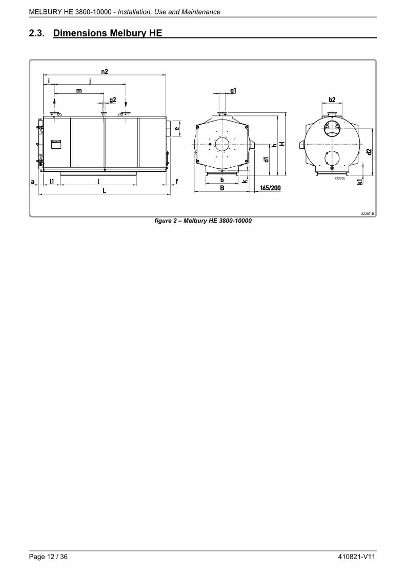
2.3. Dimensions Melbury HE
figure 2 – Melbury HE 3800-10000

MELBURY HE 3800-10000 - Installation, Use and Maintenance
18.12.2020 Page 13 / 36
Melbury HE 3800 4500 5400 6300 7400 8600 10000
Boiler feet length l mm 2700 2850 3200 4110 4510 4912 5412
Boiler feet width b mm 1150 1290 1350 1520 1610 1670 1730
Boiler height h mm 2105 2320 2435 2740 2895 3005 3100
Door thickness a mm 170 170 170 212 212 212 212
Boiler flange centre d1 mm 1110 1225 1285 1450 1530 1590 1640
Height flue d2 mm 1660 1850 1940 2120 2280 2390 2460
Flue outside diameter e mm 550 600 650 700 750 850 900
Flue length f mm 150 150 150 150 150 150 150
Ø supply - return PN6 g1 DN 200 200 200 250 250 300 300
Distance front - supply i mm 390 410 450 495 540 590 645
Distance supply - return j mm 2530 2677 2920 3160 3430 3740 4120
Ø safety valve connection PN16 g2 DN 80 80 100 100 100 125 125
Distance supply - safety valve m mm 1751 1855 2024 2190 2370 2590 2850
Discharge position k mm DN
167 2"
182 2"
187 2"
135 65
140 65
150 65
127 80
Height flue collector discharge k1
mm DN
264 11/4"
279 11/4"
284 11/4"
335 2"
340 2"
350 2"
360 2"
Distance front / feet l1 mm 600 640 650 - - - -
Catwalk width b2 mm 700 700 700 750 800 850 850
Catwalk length n2 mm 4340 4577 4977 5395 5845 6387 6987
Overall length L mm 4670 4910 5310 5771 6221 6763 7364
Boiler width B mm 1970 2170 2280 2560 2710 2810 2900
Height supply - return flange H mm 2235 2450 2565 2870 3025 3135 3230
Weight empty G kg 7025 8425 10075 13545 16040 18620 21900
Boiler water content V L 3805 5385 6060 9300 11400 13300 15120
Boiler gas content VG L 5870 7380 9450 11640 14250 17240 20720
Furnace diameter DF mm 1020 1110 1220 1270 1350 1430 1500
Furnace length LF mm 3765 3980 4360 4690 5090 5550 6120
Furnace volume VF m3 2.96 3.72 4.95 5.78 7.12 8.73 10.58

MELBURY HE 3800-10000 - Installation, Use and Maintenance
Page 14 / 36 410821-V11
2.4. Dimensions of custom made models for Melbury HE The following custom made models are available on request. They are however subject to different delivery times!
2.4.1. Vertical flue connection
CAUTION: The vertical smoke nozzles are not made on the Melbury HE.
figure 3 – Melbury HE 3800-1000
Melbury HE
3800 4500 5400 6300 7400 8600 10000
Flue outside diameter e mm 550 600 650 700 750 850 900
Flue position n1 mm 4235 4477 4872 5277 5722 6254 6849
Overall length L1 mm 4695 4960 5380 5850 6320 6900 7520
Catwalk length n mm 3940 4157 4527 4905 5325 5807 6377
The other dimensions are identical to those of the standard range.
!
MELBURY HE 3800-10000 - Installation, Use and Maintenance
18.12.2020 Page 15 / 36
22648-#
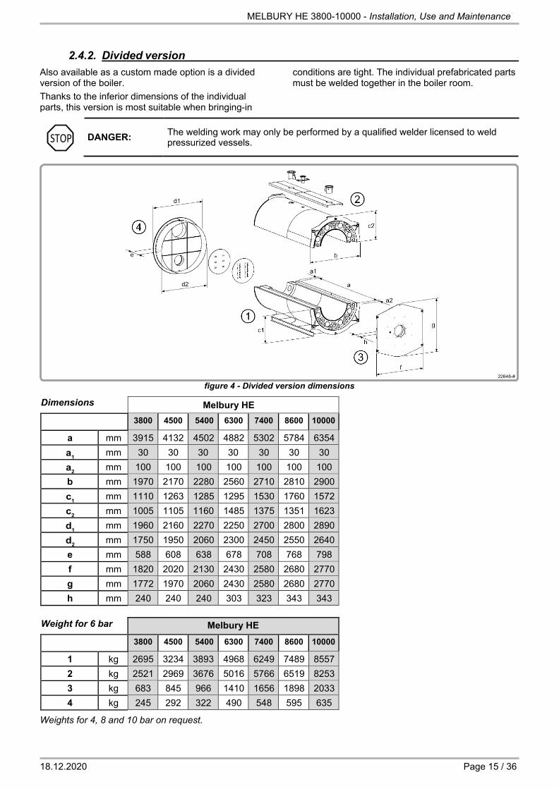
2.4.2. Divided version Also available as a custom made option is a divided version of the boiler. Thanks to the inferior dimensions of the individual parts, this version is most suitable when bringing-in
conditions are tight. The individual prefabricated parts must be welded together in the boiler room.
DANGER: The welding work may only be performed by a qualified welder licensed to weld pressurized vessels.
figure 4 - Divided version dimensions
Dimensions Melbury HE 3800 4500 5400 6300 7400 8600 10000
a mm 3915 4132 4502 4882 5302 5784 6354 a1 mm 30 30 30 30 30 30 30 a2 mm 100 100 100 100 100 100 100 b mm 1970 2170 2280 2560 2710 2810 2900 c1 mm 1110 1263 1285 1295 1530 1760 1572 c2 mm 1005 1105 1160 1485 1375 1351 1623 d1 mm 1960 2160 2270 2250 2700 2800 2890 d2 mm 1750 1950 2060 2300 2450 2550 2640 e mm 588 608 638 678 708 768 798 f mm 1820 2020 2130 2430 2580 2680 2770 g mm 1772 1970 2060 2430 2580 2680 2770 h mm 240 240 240 303 323 343 343
Weight for 6 bar Melbury HE
3800 4500 5400 6300 7400 8600 10000
1 kg 2695 3234 3893 4968 6249 7489 8557 2 kg 2521 2969 3676 5016 5766 6519 8253 3 kg 683 845 966 1410 1656 1898 2033 4 kg 245 292 322 490 548 595 635
Weights for 4, 8 and 10 bar on request.
STOP

MELBURY HE 3800-10000 - Installation, Use and Maintenance
Page 16 / 36 410821-V11
2.4.3. Different operating pressures Melbury HE boilers can be provided for the operating pressures of 4, 8 and 10 bar-g. Their dimensions and performances are identical to those of the standard
Empty weights
range of 6 bar-g, but their weights are different and the flanges of the return and flow connections of the 8 and 10 bar versions are PN16.
Melbury HE
3800 4500 5400 6300 7400 8600 10000
4 bar G kg 6332 7891 9566 12116 14717 17295 20358
8 bar G kg 7521 9258 11184 14458 17181 20174 23220
10 bar G kg 8225 9907 11923 16022 18574 21378 24754
2.5. Technical data Melbury HE
CAUTION:
The power indicated is the maximum power that the corresponding heating body model can deliver. The selected burner and the output or polluting emissions (NOx) constraints may require the burner to be set at a lower calorific flow value. For more information, please contact the after sales department.
!

MELBURY HE 3800-10000 - Installation, Use and Maintenance
18.12.2020 Page 17 / 36
2.5.1. Melbury HE Technical specifications Melbury HE, fuel oil
Melbury HE 3800 4500 5400 6300 7400 8600 10000
POWER Boiler nominal power qN (80/60°C)
max. kW
3800 4500 5400 6300 7400 8600 10000
min. 1621 2012 2518 2930 3442 4163 5127
Calorific power qF max. kW
4160 4922 5887 6852 8047 9319 10785
min. (2) 1706 2116 2649 3083 3621 4380 5393
Modulation rate at 80/60°C (2) % 41 43 45 45 45 47 50
EFFICIENCES Overall efficiency 60/80°C 100% % 91.4 91.4 91.7 91.9 92.0 92.3 92.7
Overall efficiency 50/70°C 30% % 95.0 95.0 95.0 95.0 95.0 95.0 95.0
Overall efficiency 60/80°C min qF % 95.1 95.1 95.1 95.0 95.0 95.0 95.1
Efficiency DIN4702-8, 60/75°C ɳN % 94.8 94.8 94.9 94.9 94.9 95.0 95.0
MASS FLOW Fuel oil flow max. (1)
kg/h 351.1 415.4 496.8 578.2 679.1 786.4 910.1
min. (1) (2) 143.9 178.6 223.6 260.2 305.6 369.6 455.1
Exhaust gas mass flow max. wet kg/s
1.79 2.12 2.54 2.95 3.47 4.01 4.64 min. wet
(1) (2) 0.73 0.91 1.14 1.33 1.56 1.89 2.32
EXHAUST GAS DATA, LOSSES Overpressure combustion chamber max. mbar 10.80 9.99 10.71 12.22 14.13 15.73 17.16
Exhaust gas temperature at 80/60°C
max. °C
198 196 190 185 185 178 169
min. (2) 120
Exhaust gas losses at 80/60°C max. % 8.6 8.5 8.2 8.0 8.0 7.6 7.2
Stand-by loss qB 70°C W 2724 3413 3827 4511 5118 5582 6043
HYDRAULIC DATA, Water resistance ∆t=15K
mbar 78 109 157 84 116 80 108
∆t=20K 44 62 89 47 65 45 61
Water flow max. m3/h
218 258 309 361 424 493 573
mini P/45 (P = Power in th / h provided at time t.)
Operating temperatures max. °C
95
SCO 110
Values acc. EN304 at: - lambda = 1.2, CO2 = 12.7% - T-air = 20 °C, rel. humidity = 60%, p-baro = 100 kPa
(1) : LCV = 11.85 kWh/kg (2) : Sulphur content up to 0.2%
figure 5 - Flue gas temperature diagram Melbury HE, fuel oil with clean boiler

MELBURY HE 3800-10000 - Installation, Use and Maintenance
Page 18 / 36 410821-V11
Technical specifications Melbury HE, natural gas
Melbury HE 3800 4500 5400 6300 7400 8600 10000
POWER Boiler nominal power qN (80/60°C)
max. kW
3800 4500 5400 6300 7400 8600 10000
min. 880 1160 1473 1582 1935 2332 2907
Calorific power qF max. kW
4166 4929 5894 6861 8055 9328 10795
min. (3) 916 1208 1532 1647 2014 2425 3023
Modulation rate at 80/60°C (3) % 22 25 26 24 25 26 28
EFFICIENCIES Overall efficiency 60/80°C 100% % 91.2 91.3 91.6 91.8 91.9 92.2 92.6
Overall efficiency 60/80°C 30% % 95.7 95.8 95.9 95.8 95.8 95.9 96.1
Overall efficiency 60/80°C min qF % 96.1 96.1 96.1 96.1 96.1 96.1 96.2
Efficiency DIN4702-8, 60/75°C ɳN % 95.1 95.1 95.3 95.3 95.3 95.4 95.6
MASS FLOW Gas flow, NG type E max. (1) (2)
nm3/h 418.0 494.6 591.4 689.0 808.0 936.0 1083.0
min. (1) (2) 92.0 121.2 153.8 165.0 202.0 243.0 303.0
Exhaust gas mass flow max. wet kg/s
1.74 2.06 2.46 2.87 3.36 3.89 4.51 min. wet
(1) (3) 0.38 0.50 0.64 0.69 0.84 1.01 1.26
EXHAUST GAS DATA, LOSSES Overpressure combustion chamber max. mbar 11.01 10.18 10.91 12.46 14.4 16.03 17.48
Exhaust gas temperature at 80/60°C
max. °C
199 197 191 186 185 179 170
min. (3) 95
Exhaust gas losses at 80/60°C max. % 8.7 8.6 8.3 8.1 8.0 7.7 7.3
Stand-by loss qB 70°C W 2724 3413 3827 4511 5118 5582 6043
HYDRAULIC DATA Water resistance ∆t=15K
mbar 78 109 157 84 116 80 108
∆t=20K 44 62 89 47 65 45 61
Water flow max. m3/h
218 258 309 361 424 493 573
mini P/45 (P = Power in th / h provided at time t.)
Operating temperatures max. °C
95
SCO 110
Values acc. EN303-3 at: - lambda = 1.15, CO2 = 10% - T-air = 20 °C, rel. humidity = 60%, p-baro = 100 kPa
(1) : LCV = 9.97 kWh/nm3
(2) : nm3 at 0°C, 1013 mbar (3): S max = 10 mg / nm3
figure 6 - Flue gas temperature diagram Melbury HE, natural gas with clean boiler

MELBURY HE 3800-10000 - Installation, Use and Maintenance
18.12.2020 Page 19 / 36
Technical specifications Melbury HE, heavy fuel Melbury HE
3800 4500 5400 6300 7400 8600 10000 POWER
Boiler nominal power qN (80/60°C) max. kW 3300 4000 4700 5600 6700 8100 9700
Calorific power qF max. (1) kW 3579 4336 5075 6047 7243 8751 10443
(1): LCV = 11.53 kWh/kg, 970 kg/m3, 1% S
Respect the operating conditions according to chapter 2.1. Further data on request.
MELBURY HE 3800-10000 - Installation, Use and Maintenance
Page 20 / 36 410821-V11
2.6. Correction values for different operating conditions 2.6.1. Flue gas temperature correction values
Average boiler water temperature tm °C 50 60 70 80 90 100
Flue gas temperature difference ∆t K - 16 - 8 ± 0 + 8 + 16 + 24
Excess air λ − 1.10 1.15 1.20 1.25 1.30 1.35
Flue gas temperature difference ∆t K - 6 - 3 ± 0 + 3 + 6 + 8
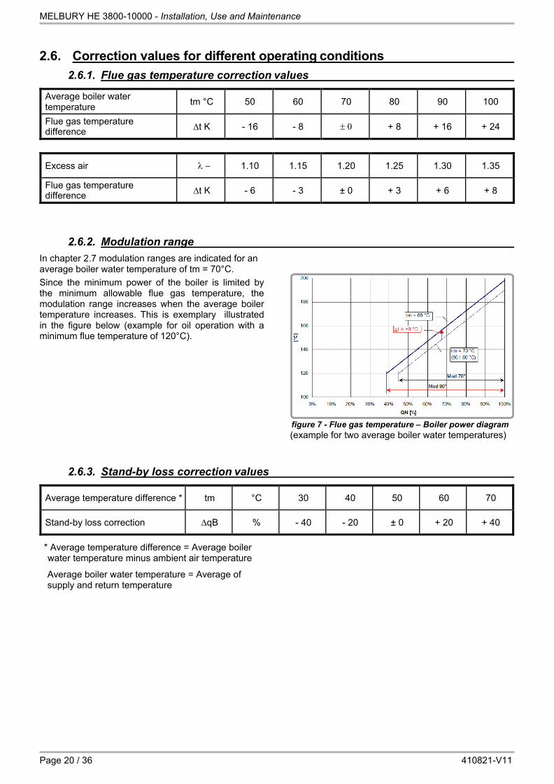
2.6.2. Modulation range In chapter 2.7 modulation ranges are indicated for an average boiler water temperature of tm = 70°C. Since the minimum power of the boiler is limited by the minimum allowable flue gas temperature, the modulation range increases when the average boiler temperature increases. This is exemplary illustrated in the figure below (example for oil operation with a minimum flue temperature of 120°C).
figure 7 - Flue gas temperature – Boiler power diagram (example for two average boiler water temperatures)
2.6.3. Stand-by loss correction values
Average temperature difference * tm °C 30 40 50 60 70
Stand-by loss correction ∆qB % - 40 - 20 ± 0 + 20 + 40
* Average temperature difference = Average boiler water temperature minus ambient air temperature
Average boiler water temperature = Average of supply and return temperature
MELBURY HE 3800-10000 - Installation, Use and Maintenance
18.12.2020 Page 21 / 36
3. BOILER CONTROL PANEL
INFORMATION:
For hot water installation: o Maximal operating temperature: 95°C when the boiler is managed by a
Navistem B1000 ou B2000. o Maximal operating temperature: 105°C if the regulation system is compatible
with this work. In any case, this device has been designed according to EN 14394. The safety limit thermostat does not exceed 110 °C.
3.1. Description Several types of control panel are assigned to Melbury HE. The NAVISTEM B1000 control panel without heating regulator is used to manage the operation of a burner at 1 or 2 stages using a double regulation thermostat. It does not protect the boiler against condensation in the steel heater housing, ensuring a minimum return temperature of 50° C with oil and 60° C with gas. The NAVISTEM B2000 control panel with RVS 63 heating regulator enables management of the operation of the burner (speed 1 / 2 or modulating), heating circuits and domestic hot water production. The RVS 63 regulator is equipped with digital logic enabling the boiler to be protected against cold starts. It also enables management of the flow and temperature of return water by acting on the three-way valves of the heating circuits or three-way valve for heating the boiler return temperature.
The control panels are supplied ready to be connected. The regulators must be set according to the recommendations in the instructions provided in the control panel to protect the boiler against condensation. Settings must also be adapted to comply with the hydraulic system configuration (circuits for heating, domestic hot water, etc.). The steel sheet housing is ready to be mounted on top of the boiler cover or on the carrier located on the side cover. The electrical diagram is attached to the control panel.
3.2. Basic equipment NAVISTEM B1000 and B2000
- Burner ON / OFF switch - 6.3 A H 250VAC fuse for burner - 6.3 A H 250VAC fuse(s) for regulator(s) - Safety thermostat - Regulating thermostat for 1st and 2nd speed (2nd
speed inactive for a NAVISTEM B2000 panel with RVS 63 regulator)
- Overheat indicator - Burner safety indicator - External fault indicator - Water thermometer
3.3. Additional equipment - Timer and pulse counter speeds 1 and 2 - Dry contacts module / overheating fault, burner fault,
burner operation at speed 1, burner operation at speed 2, external fault indicators
- Dry contacts module and burner reset
- Three-phase burner power supply - RVS 46 additional heating regulator (management of
a mixer valve circuit)

MELBURY HE 3800-10000 - Installation, Use and Maintenance
Page 22 / 36 410821-V11
3.4. Heating regulators
3.4.1. RVS 46 regulator (optional on the NAVISTEM B2000 control panel)
Regulator not included in the basic panel (sold as additional equipment) : - Slave heating regulator to control a mixer valve
heating circuit - Return temperature mixer valve protection: protection
against condensation in the steel heater when the RVS 63 outputs are already used to manage two heating circuits.
3.4.2. RVS 63 regulator (included as standard with NAVISTEM B2000 control panel)
Regulator enabling : - A burner to be run at one speed, two speeds or
modulating - Running a direct heating circuit - Running two heating circuits or one heating circuit
and a mixer valve protecting the heater in return temperature
- Running domestic hot water preparation - Achieve a tile effect with one or more other boilers
equipped with a SIEMENS regulator (LPB communication bus).
3.5. Burner cables
Depending on the order, sets of cables with standardised 7 and 4 pin connectors (DIN 4791) can be supplied with the control panel. The burners used should be equipped with suitable connectors.

MELBURY HE 3800-10000 - Installation, Use and Maintenance
18.12.2020 Page 23 / 36
4. INSTALLATION GUIDE
4.1. Boiler room and boiler room ventilation
The boiler room must be arranged in compliance with local regulations and installation specifications. Particular attention should be paid to the ventilation of the boiler room. Supply of combustion air must be guaranteed (non-shut opening).
Minimum air requirement is 1.6 m3/h for each kW of boiler power. Minimum free section of combustion air opening is 6 cm2 for each kW of boiler power.
CAUTION:
The combustion air must not have high dust concentrations. Furthermore, it must be free of halogens (chlorine and fluorine compounds). An excessive presence of halogen in the combustion air leads to great corrosion damage. The maximum permitted amount of halogen in the combustion air is 5 ppm. Halogen compounds are found in spray cans, thinners, cleaning agents, degreasing agents and solvents, among others. In addition, halogen emissions are strongly suspected in the vicinity of dry cleaners', hair dressing salons, swimming pools, printing offices and washing machines installed in the same room. In the case of doubt, the perfect quality of the combustion air must be ensured with an external air intake. Make sure that there is a minimum loss of pressure, since this could impair the performance of the burner.
4.2. Planning dimensions
4.2.1. Space required
It must be possible to open the furnace door, including burner, by 90°.
E = Burner length
A = E + d + 150 mm
figure 8 - Planning dimensions
4.2.2. Boiler base If the floor of the boiler room is moist or loose, a sufficiently high boiler base must be provided. Moisture does not go well with electrical equipment! A base is also a good idea if the height is not sufficient for installing the burner. Otherwise, no base is needed for the boiler series.
!

MELBURY HE 3800-10000 - Installation, Use and Maintenance
Page 24 / 36 410821-V11
4.2.3. Boiler support It is possible to mount the boiler on vibration dampers (available as option) to reduce noise transmission
caused by vibrations.
figure 9 - With vibration dampers figure 10 - Without vibration dampers
Melbury HE 3800 4500 5400 6300 7400 8600 10000
Distance wall - boiler body front D mm 3800 4000 4400 4800 5200 5700 6200 Boiler length T mm 4350 4590 4990 5409 5859 6401 7002
Distance wall - boiler back U mm 1150 1150 1150 1150 1150 1150 1150 Distance wall - boiler flank (*) V mm 1000 1000 1000 1000 1000 1000 1000
Boiler feet length I mm 2700 2850 3200 4110 4510 4912 5412 Boiler feet width b mm 1150 1290 1350 1520 1610 1670 1730
Measure d mm 15 15 15 42 42 42 42
Silent block length e mm 706 / 562 706 634 634 634 670 670
Silent block width S mm 50 50 60 75 75 85 85 Number of silent blocks 6 / 2 8 10 12 14 14 16
U-girder width S1 mm 60 60 65 80 80 90 90
* The dimension can be reduced to 200 mm, as long as this does not impair the operation of the control panel and the ability to open a nearby furnace door.
The mounting instructions for the silent blocks can be found in the separate assembly guide. After this, you can start installing the connection tubes on the water and flue gas side.
CAUTION: Once the boiler is filled up, it will come down by further 3-5 mm.
!

MELBURY HE 3800-10000 - Installation, Use and Maintenance
18.12.2020 Page 25 / 36
4.3. Hydraulic connection For the hydraulic connection of the heating system and water heaters– in particular with regards to technical safety devices such as safety valves, expansion tanks, etc. – refer to generally accepted engineering rules as well as locally applicable standards, specifications and regulations. If boilers are installed in garret-based heating plants or at the highest point of the heating system, then boilers will have to be provided with additional safety devices (such as protections against water shortage). Observe the minimum operating pressure as specified in chapter 2.2, page 11. Act in compliance with local safety regulations in force at all times. Before connecting the boiler to an old installation, it is necessary to flush the whole heating system. It is also recommended to provide for a sludge separator. To protect the boiler from return temperatures below the limits as specified in chapter 2.1, page 11, the boiler should be provided with an automatic return temperature regulation. If the boilers are combined with a water heater, make sure that their size and capacity correspond to the installed boiler capacity.
A component-tested membrane safety valve must be used to reliably prevent the permitted operating overpressure in the water heater from being exceeded; it must not be possible to shut the valve off from the water heater. When water heaters with an electrical auxiliary heater are used, a reliable check valve must be installed in the charging tube between the boiler and the water heater. Boiler’s maximum operating pressure and the maximum operating temperature are given in chapter 2.1, page 11. No minimum level of the amount of circulating water is required. Damage can occur from corrosion when oxygen continuously enters the heating water through open installations, expansion tanks that are too small, floor heaters with pipe material that is not oxygen-tight, etc. If this cannot be prevented, additional measures are necessary in the form of correctly used oxygen binding agents or chemicals. If it is not possible to realize an installation without oxygen entrance, a system separation must be set up using heat exchangers.
4.4. Electrical installation 4.4.1. General notice
The electrical installation must be carried out by an authorised electrician from beginning to end. In carrying out the electrical installation, local regulations as well as any standards and specifications in force must be complied with.
The mounting instructions for the control panel and its support can be found in the separate assembly guide. The wiring diagram is joined with the control panel.
CAUTION:
Electrical connections, especially the connection to the mains, should only be made after all other assembly and installation work has been completed. Locally made installations (raceways, etc.) must not be clamped to the boiler’s cladding!
4.4.2. Connecting to the supply mains
External supply is one-phase, alternate current type 230VAC, 50Hz or three-phase alternate current 400VAC, 50Hz, both max. 16A. The apparatus is internally protected by a 6,3A delayed-action fuse (burner/boiler) and by an additional 6,3A delayed- action fuse for each additional governor or module. The quality of the supply must respect norm EN50160 (voltage ±10% maxi, frequency ±1%).
All external connection cables to the boiler must be suitably laid on site. A DIN VDE 0116-compliant disconnecting device must be provided on site.
!

MELBURY HE 3800-10000 - Installation, Use and Maintenance
Page 26 / 36 410821-V11
4.4.3. Connecting the burner The electrical connections of the burner (power supply and control) are made by the customer in accordance with the requirements of the burner.
4.5. Turbulators Thanks to the turbulators, which are to be inserted in the smoke tubes, the combustion gas temperature can be controlled. All smoke tubes in the third pass must equally be provided with turbulators. These smoke tubes are
those that are open on the rear part, in the direction of the combustion gas collector. The mounting instructions can be found in the separate assembly guide.
Melbury HE
3800 4500 5400 6300 7400 8600 10000 Number of turbulators 54 63 72 80 84 91 99 Outer diameter Da mm 72 Edge diameter d mm 10 Pitch A mm 80 Length L mm 3100
figure 11 - Turbulator

MELBURY HE 3800-10000 - Installation, Use and Maintenance
18.12.2020 Page 27 / 36
4.6. Connecting the burner 4.6.1. Burner mating dimensions / orientation possibilities for Melbury HE
figure 12 - Burner mating dimensions for Melbury BE
Melbury HE
3800 4500 5400 6300 7400 8600 10000 FURNACE
Length FRL mm 3765 3980 4360 4690 5090 5550 6120 Diameter FR mm 1020 1110 1220 1270 1350 1430 1500
BURNER CONNECTION Burner admittance diameter M mm 480 510 540 580 580 620 Burner mini tube max (qN max) length (*) max (qN low NOx)
P
mm
290 350 370 390 440 390 430 500 590 540 580 600
Screw hole centre diameter Lk mm 580 640 680 680 700
8xM12, -15° 4xM16, +20° / 4xM12, -20° Maximum door load from burner weight (**) kg x m 370 440 500 745 850 915 980
BURNER ORIENTATION Max. swivel radius R mm 1365 1505 1615 1780 1895 1985 2065 Distance boiler axle - pivot D1 mm 860 960 1015 1150 1225 1275 1320 Distance door flange - pivot D2 mm 130 172 Door thickness T mm 240 292 312 332
* Burner tube lengths without consideration of an eventual intermediate flange
** Load as burner weight x distance burner center of gravity - door. When necessary use a burner support.

MELBURY HE 3800-10000 - Installation, Use and Maintenance
Page 28 / 36 410821-V11
4.6.2. Burner assembly The front door of models Melbury HE 3800-10000 is provided with a norm-conform flange to fit the burner. An additional intermediate flange may nevertheless be necessary to fit the burner. Models Melbury HE 3800-10000 will in
most cases require a special flange. This intermediate flange and related screws must be ordered separately or supplied by the burner manufacturer.
CAUTION:
The intermediate space between the burner tube and door hole must be filled with the supplied insulating material before the burner is commissioned (see separate assembly guide).
4.6.3. Connection to the fuel supply The whole installation may only be carried out by a licensed installation company. The installation must be performed in accordance with local regulations. Particular care is to be taken that measures are foreseen to prevent any burner start when the boiler door is open. Good practice is to connect the fuel
supply to the burner in such a way that the supply line has to be disconnected in order to be able to open the boiler door. Another possibility is to attach the burner cables with glands in such a way that the connectors on the burner have to be pulled to open the door.
CAUTION: Customer installations (oil tubes, etc.) must not be attached to the boiler cladding!
Gas burner Observe the separate instructions of the supplied burner. The gas installation must be dimensioned in accordance with the gas flow rate and the available gas pressure. A shut-off valve must be installed in the gas supply line to the burner.
INFORMATION:
Oil burner
Before the gas burner is connected to the gas line, it must be ensured that the line has been blown through and is free from particles and chips. The gas line must be checked for leakage during commissioning and after each disconnection (leak detector spray). The installation may only be operated using gas of the intended quality – observe additional panel on boiler!
Observe the separate instructions of the supplied burner.
4.6.4. Part load operation
Stick to the minimum power of the supply heat according the technical data, chapter 2.7 and 2.8.
!
!

MELBURY HE 3800-10000 - Installation, Use and Maintenance
18.12.2020 Page 29 / 36
4.7. Flue gas system The Melbury HE boilers have been developed using the latest technologies. The perfect balance existing between boiler and chimney ensures optimal fuel use and economical system operation as a result.
The pertinent rules of technology and good practice as well as the country-specific regulations and valid standards must be observed.
4.7.1. Section determination
Sections must be calculated for boilers without draught. Fuel type, power output, combustion gas temperature and quantity, chimney construction and height are all important elements in determining sizes.
4.7.2. Flue gas tubes We recommend the use of flue gas tubes made from acid-resistant, non-corrosive materials. The tube must be laid and introduced in the chimney to an inclination of 30-45° to minimize pressure loss. The tube will have to be inserted in such a way as to prevent any condensation reversal from the chimney down into the boiler. To avoid vibration transmission, combustion gas tubes must be fitted with adequate sleeve tubes or clamps. Connections exceeding 1 m in length should be insulated.
At the same time, ensure that the measuring pipes extend beyond the insulation and that flanges and cleaning covers remain accessible. The chimney must be designed so that it is gas and pressure-tight as well as moisture-insensitive and acid- resistant.
MELBURY HE 3800-10000 - Installation, Use and Maintenance
Page 30 / 36 410821-V11
5. OPERATING CONDITIONS
5.1. Fuels
The Melbury HE boilers are designed for operation with fuel oil EL and natural gas. Models Melbury HE 3800-10000 can also be operated on heavy fuel.
CAUTION: The use of other fuels such as for example biogas is only permitted with the express approval of the manufacturer.
5.2. Combustion air
The combustion air must not have high dust concentrations.
CAUTION:
Furthermore, it must be free of halogens (chlorine and fluorine compounds). An excessive presence of halogen in the combustion air leads to great corrosion damage. Make sure that no paints, thinners, cleaning agents, degreasing agents, solvents, chlorine containers, etc. are stored in the boiler room!
5.3. Filling the installation and water quality
The installation must be thoroughly rinsed before it is finally filled. When filling for the first time and refilling, check the quality of the water in accordance with the values recommended in chapter "Water quality", page 5. Poor water quality leads to damage in heating installations from calcification and corrosion. On the other hand, the service life, functional reliability and
efficiency can be increased using appropriately treated water. During the filling process, the circulation pumps should be switched off and all ventilating valves opened, so that the air in the system can completely escape. The filling process is finished when the operating pressure has been reached.
5.4. Protection against corrosion Normally, no corrosion problems arise if systems are properly designed and installed and are run according to these instructions; consequently there is no need to use chemical additives. However, if water is of poor quality or if oxygen seeps from the air into the heating system (expansion chambers open, expansion/supply chambers too small, plastic tubes without diffusion blocking in floor heating) damages are something which cannot be completely excluded. If you happen to
use chemical additives in your system, make sure that they are effective, harmless and above all appropriate for the materials your system is made of. Enquire with your chemical additive supplier. In this case, you will need to arrange for a specialist water company to carry out annual quality checks on the water used in the heating system in order to avoid any damage to the system.
5.5. Requirements for operation
The maximum operating pressure and the maximum temperature to be observed are listed on the type plate. The minimum temperatures to be observed are given in chapter 2.1. It is strictly recommended to maintain the boiler in operation during several hours after a cold start-up in order to evaporate condensates that are inevitably formed in any boiler during cold start-up.
!
!

MELBURY HE 3800-10000 - Installation, Use and Maintenance
18.12.2020 Page 31 / 36
6. OPERATION
Read this section of the manual with great care and get an installer to explain the heat producing system in all its different aspects: regulation and control. If you suspect that the boiler or other part of the system is frozen, do not start the system.
Please also note the operating conditions described in chapter 5.
Note for Melbury HE 3800-10000: The boiler door screws on the side of the axis of rotation must NOT be loosened!
6.1. Commission Before commissioning the system, please check: - Whether the burner and the fuel system have been
checked and the settings of the burner correspond to the required performance of the unit. Observe the instructions for putting the burner into operation,
- Whether any foreign matter has been removed from the boiler furnace,
- Whether the turbulators have been properly installed, - Whether the clearance space around the burner tube
has been filled with insulation material, - Whether the boiler door is closed properly, - Whether the heating system has been filled up with
water and completely vented, - Whether the thermostats are properly regulated and
whether the heating system governor has been set according to the necessary parameters by the support service or by the installer,
- Whether the regulation and safety devices work properly,
- Whether all shut-off valves (of both water and burner) have been opened,
- Whether the circulation pumps work, - Whether the air supply is ensured and the flue outlet
is free.
The inside of the burner door is built using insulating, refractory concrete. The residual humidity present in the concrete, resulting from the manufacturing process, may, during the initial operating phase, release steam and form water droplets on the door. The steam must be allowed to escape throughout the pre-heating phase before reaching the operating temperature. This process can last one week. The increase in operating power of the burner must be progressive during this period.
INFORMATION: Pre-heating may result in the appearance of cracks. Small shrinkage splits and cracks do not hinder operation and do not represent a defect; they are unavoidable.
The unit is put in operation by actuating the ON/OFF switch of the control panel (position I) or possibly, depending on the installation, by actuating a switch on the burner or within the central control cabinet.
6.2. Decommission The unit is put out of operation by actuating the ON/OFF
switch of the control panel (position O) or possibly, depending on the installation, by actuating a switch on the burner or within the central control cabinet.
Should the heat producing system remain off for several weeks, we recommend that the following measures be taken:
- Close the fuel supply, - Clean and protect the heating surface of the boiler.
Your installation contractor will be pleased to give you some advice.
- In case of frost warnings, drain the system or add an anti-freeze product and follow the instructions given in chapter 5.4.

MELBURY HE 3800-10000 - Installation, Use and Maintenance
Page 32 / 36 410821-V11
6.3. First steps to take in case of failure In the event of system operational failure, perform the checks in the table below. Also check the governor set- up. If the failure cannot be eliminated, call a reliable engineer or your support service.
Problem Possible cause Solution Burner not functioning No power. Check fuse, switch on main or safety
switch. Connect supply and burner plug.
Burner LED is on.
Press burner reset button.
No oil.
Add oil.
Gas pressure insufficient. Call the gas board.
Overheat temperature LED is on. Safety thermostat has come into operation.
Fix the cause, wait until temperature has dropped below overheat setpoint then reset the safety thermostat by pushing the pin.
External default LED is on. Fix the cause.
No heat release to consumers Incorrect operation type setting on governor.
Circulation pump blocked.
Water level or system pressure.
Shut-off elements on supply and return lines closed.
Set up type of operation and heating program.
Remove locking screw, turn shaft until no more resistance is left.
Top up and ventilate.
Open them.

MELBURY HE 3800-10000 - Installation, Use and Maintenance
18.12.2020 Page 33 / 36
7. MAINTENANCE
To maintain the high degree of efficiency of the unit, it is necessary to service it regularly. Depending on the type of operation, annual or semi-annual servicing is recommended. The boiler and firing must be inspected by a qualified
specialist in accordance with the official regulations. Before performing any work on the unit, it must be disconnected from the mains and the fuel supply must be shut off.
DANGER:
The device contains components made of synthetic silicon mineral fibers (ceramic and glass fibers, insulation wool). In order to avoid all types of health hazards, suitable clothing and a protective mask must be worn for work on or with these components.
7.1. Periodical checks and maintenance operations
- Check manometer with circulation pump off. Low water or pressure level indicates that the system must be filled up with water.
- Check that the expansion chambers function properly. - Check safety valves as well as heating and hot water
system blowers.
- Carry out burner maintenance according to the recommendations given in the burner manual.
- Check fuel oil level. - Clean boiler and chimney.
7.2. Boiler cleaning
Boiler should be cleaned by your chimney sweeper and engineer.
The cylindrical type construction of the boilers makes cleaning much easier to perform. However, we recommend that heating surfaces in fuel oil boilers be cleaned with appropriate chemical products. Your installation contractor, as an engineer, will know how to best advise you.
- Turn off burner, - Disconnect burner plug from socket, - Loosen boiler door screws and rotate door together with
burner. Attention: On Melbury HE 3800-10000 do NOT loosen screws on the side of the axis of rotation!
- Remove the turbulators,
- Clean the combustion chamber and smoke tubes, - Disassemble the lid on the back of the boiler and clean
the flue gas collector, - Re-install the cleaned turbulators following the
instructions given in chapter 4.5 of these instructions, - Re-install lid and close furnace door, - Start up burner again.
7.3. Burner maintenance The regular maintenance of the burner (body, jet, burner head, igniter, pump filters) must be carried out by a qualified specialist in accordance with the instructions of the burner.
After the work has been completed, the settings of the burner must be checked to ensure that they meet the performance requirements of the unit.
8. SPARE PARTS
Spare parts on request.
STOP

Wessex House New Fields Business Park Stonsford Road, Poole Dorset H17 ONF Tel.: 01202 662500 Fax.: 01202 662522 [email protected] www.hamworthy-heating.corn
CAUROIR SITE 1 route de Solesmes
FR - 59400 CAUROIR