Embed Size (px)
Citation preview
Document number: 62.120.001 Document title: FGM 160 Installation and Hook-Up
Instructions
Scope: ISO 9001:2008 §7.2.3
Additional Information (when applicable)
E 2014.07.14 Updated installation guidelines AP MS KP MB KP
D 2013.11.29 Proofread and updated AP MR CT MB MW
C 2013.02.14 Removed from User Manual, updated: changes in content.
MKJ KH - MW MW
B 2009.05.29 Updated information MS DIÅ RT N/A AAJ
A 2007.11.26 Issued for Fluenta release; moved to
User Manual MS DIÅ TM N/A AAJ
Rev. index
Issue date Reason for issue Author Review Review Review by QA
Approved
Replacement for: Total pages:
41 Fluenta source doc. (for translations):

FGM 160 Installation and Hook-Up Instructions
62.120.001 Page 2 of 41
TABLE OF CONTENTS
1. Purpose .......................................................................................................... 5
2. Abbreviations / Definitions............................................................................. 5
2.1 Abbreviations .............................................................................................. 5 2.2 Definitions .................................................................................................. 5
3. General ........................................................................................................... 6
4. Unpacking....................................................................................................... 6
4.1 Inspection of Goods ..................................................................................... 6 4.2 Ex-Classification Marking .............................................................................. 6 4.3 Equipment Information ................................................................................. 7 4.4 Manufacturer Information ............................................................................. 7
5. Transducer/Probe Installation ....................................................................... 7
5.1 Installation of Transducer Holders .................................................................. 7 5.1.1 Space Requirements ............................................................................ 7
5.1.1.1 Space requirements for the Transducer Full Size, TFS ................. 8 5.1.1.2 Space requirements for the Temperature and Pressure
Transmitters ..................................................................................... 9 5.2 Mounting the Transducer Holders ..................................................................10
5.2.1 Orientation ........................................................................................10 5.2.1.1 Horizontal Flare Pipe ............................................................. 10 5.2.1.2 Vertical Flare Pipe ................................................................ 11
5.2.2 Cold Tapping .....................................................................................12 5.2.3 Using the Sighting Tool .......................................................................16 5.2.4 Hot Tapping Transducers Full Size, TFS .................................................18
5.3 Mounting the Ultrasonic Transducers .............................................................18 5.3.1 Determining the Correct Position for the Transducers..............................18 5.3.2 Edge Flush Transducer Mounting ..........................................................19
5.3.2.1 Setting the correct insertion depth ......................................... 19 5.3.2.2 45° installations ................................................................... 20 5.3.2.3 48°/42° installations ............................................................ 21
5.3.3 Insertion of the Transducer Full Size (TFS) ............................................22
6. Field Computer Installation .......................................................................... 22
6.1 The Field Computer Mounting Frame .............................................................22 6.2 Electrical Wiring ..........................................................................................23
6.2.1 Cable Preparations .............................................................................24 6.2.2 Power Cable ......................................................................................25 6.2.3 Ultrasonic Transducer Cables ...............................................................25 6.2.4 Connecting the Pressure and Temperature Transmitters ..........................28 6.2.5 Control Room and Data Cables .............................................................30
6.2.5.1 DCS Port, Modbus ................................................................ 30 6.2.5.2 Foundation Fieldbus Output ................................................... 30 6.2.5.3 Service Port ........................................................................ 31 6.2.5.4 Current Loop Outputs (4-20mA) ............................................ 31 6.2.5.5 HART Output ....................................................................... 36 6.2.5.6 Pulse/Frequency/Level Output ............................................... 37
6.3 Upgrading from the FGM 130 .......................................................................39
7. References .................................................................................................... 40
8. Appendix I - Space requirements for the TFS ............................................... 41

FGM 160 Installation and Hook-Up Instructions
62.120.001 Page 3 of 41
TABLE OF FIGURES
Figure 1: Fluenta’s minimum straight up- and downstream distances to disturbances. ... 8 Figure 2: Distance requirements for the pressure and temperature transmitters. ........... 9 Figure 3: The preferred and non-preferred orientation for horizontal pipe installation. ...10 Figure 4: Vertical flare boom with the transducer holders and transducers installed. .....11 Figure 5: Cold tapping – placement of spot marks. ...................................................12 Figure 6: Cold tapping – centerlines. .......................................................................12 Figure 7: Cold tapping – contour marker. ................................................................12 Figure 8: Marking a line around the pipe using a marking band. .................................13 Figure 9: Machined hole. .......................................................................................14 Figure 10: Machined holder. ...................................................................................14 Figure 11: As you raise the transducer holder, you must also move it backwards to keep
the centering correct. ............................................................................................14 Figure 12: Welding jig and transducer holder. ..........................................................15 Figure 13: Transducer holder welded to the pipe. .....................................................15 Figure 14: The sighting tool for the 42°/48° transducer holders .................................16 Figure 15: The sighting tool for 45° transducer holders. ............................................16 Figure 16: The stop washer for the sighting tool for the 42°/48° transducer holders. ....16 Figure 17: A 45° sighting tool mounted in a transducer holder. ..................................16 Figure 18: A 42°/48° sighting tool with stop washer mounted in a transducer holder. ...16 Figure 19: Look through the holes on the sighting tool. Rotate the sighting tool on the
left to get a correct alignment. ...............................................................................17 Figure 20: A good alignment. .................................................................................18 Figure 21: A bad alignment....................................................................................18 Figure 22: The gas-proof measuring tool. ................................................................18 Figure 23: A schematic of the gas-proof measuring tool. ...........................................19 Figure 24: Insertion depth. ....................................................................................19 Figure 25: Retracted tranducers distance. ...............................................................20 Figure 26: Edge-flush position for a 45° transducer holder. ........................................20 Figure 27: Edge-flush position for a 42° transducer holder. ........................................21 Figure 28: Edge-flush position for a 48° transducer holder. ........................................21 Figure 29: Mounting the Transducer Full Size. ..........................................................22 Figure 30: The FGM 160 Field Computer mounting frame versions. .............................23 Figure 31: Ex-e enclosure terminals overview. .........................................................24 Figure 32: Power to the FGM 160. ..........................................................................25 Figure 33: Connecting the Ultrasonic Transducers to the FGM 160. .............................26 Figure 34: Connection details for ultrasonic transducers. ...........................................27 Figure 35: Pressure and temperature transmitter hook-up. ........................................28 Figure 36: FGM 160 – 4-20 mA pressure and temperature transmitter connections. ......29 Figure 37: Pressure and Temperature HART transmitter connection. ...........................29 Figure 38: Data and Signal Cables. .........................................................................30 Figure 39: Foundation Fieldbus Connection ..............................................................31 Figure 40: Active output current loop(s), wiring .......................................................32 Figure 41: Passive output current loop(s), wiring ......................................................33 Figure 42: Current loop outputs, details ..................................................................34 Figure 43: Current loop outputs, Load/Voltage limitations ..........................................35 Figure 44: Current loop active output, High side load and Low side load ......................35 Figure 45: Current loop passive output, High side load and Low side load ....................35 Figure 46: Multiple current loop outputs, Active output configuration ..........................36 Figure 47: Multiple current loop outputs, Passive output configuration ........................36 Figure 48: FGM 160 Pulse/frequency output connections ...........................................38 Figure 49: FGM 160 Pulse/frequency output connections. Without external power ........38 Figure 50: FGM 130 –> FGM 160 upgrade ...............................................................39 Figure 51: Space requirements for the TFS ..............................................................41

FGM 160 Installation and Hook-Up Instructions
62.120.001 Page 4 of 41
LIST OF TABLES Table 1: The space requirements for Transducer Full Size, TFS. ................................... 8 Table 2: Min./max. loop resistance at typical loop voltages. .......................................34

FGM 160 Installation and Hook-Up Instructions
62.120.001 Page 5 of 41
1. PURPOSE
The purpose of this procedure is to provide a traceable point-by-point installation
guideline for the Fluenta Flare Gas meter, Field Computer (FGM 160) system. This document provides details on the different options that are available on the
FGM 160 system, the installation of the base system, and the optional configurations. The optional configurations include the two types of transducer, possible upgrade from previous Fluenta Flare Gas Meters, and the different
interfaces available from the Flow Computer to the Plant Control System. The procedure also provides a means to establish an “Installation and Hook-Up
Record” to document the installation.
2. ABBREVIATIONS / DEFINITIONS
2.1 Abbreviations
FGM Flare Gas Meter
TFS Transducer Full Size
2.2 Definitions
Metering Spool Section A section of pipe that has the transducer, pressure, and temperature holders already mounted.
Cold Tapping Mounting the transducer, pressure, and temperature
holders on a section of the flare pipe which has been shut off from the flare system.
Hot Tapping Mounting the transducer, pressure, and temperature holders on a section of the flare pipe which is an active
part of the flare system. Center flush The center of the tip of the transducer is flush with the
inner wall of the pipe.
Edge-Flush The part of the transducer tip that is inserted furthest into the transducer holder/ball valve, and is flush with
the inner wall of the pipe. Insertion depth The distance from the tip of the transducer to the
raised part of the transducer flange.

FGM 160 Installation and Hook-Up Instructions
62.120.001 Page 6 of 41
3. GENERAL
The FGM 160 system supplied from Fluenta is designed to work with no
substantial pre-installation preparations. Due to the complexity and the required accuracy of the measurements, it is mandatory to obtain a very high degree of
precision and care during all phases of the installation. This procedure includes the required steps from unpacking to commissioning. After unpacking and inspection of the received goods has been carried out, the
system should be ready for installation. The description of the installation of the system is divided into subsections as follows:
• Transducer/ Probe installation. • FGM 160 Field Computer installation.
NOTE: Installation of transducers is forbidden and causes loss of warranty,
unless it is performed by certified personnel. Certified personnel includes Fluenta service engineers, service engineers of Fluenta agents
who have received proper training and operators who have attended and completed Fluenta’s 2-day Operators Training Course. Installation of computers should be performed for preparation, but it is forbidden to
energize them without a properly trained person (same condition as for transducers) to supervise it. Additionally, any interference within
transducers and computers (opening, configuring, etc.) is forbidden and will cause loss of warranty.
4. UNPACKING
4.1 Inspection of Goods
Installation of the equipment supplied by Fluenta must never occur without the
inspection of the supplied goods carried out first. This should be performed according to the instructions and tasks described in:
FGM 160 – Preservation, Packing, Unpacking and Storage Procedure[1].
It is important to verify the goods according to the packing list and inspect for damages caused by transportation, and to save packing material for storing and reshipping of the equipment, if required.
Fluenta ensures that equipment is packed and shipped properly. Mechanical damage caused during transportation on Ex-works terms or on customer’s site
will not be considered as warranty.
4.2 Ex-Classification Marking
Make sure that the FGM 160 is certified for the area and hazardous zone it is intended to be installed in. The Ex-Classification marking of the equipment is described in:
FGM 160 – Hazardous Area Installation Guidelines [2].

FGM 160 Installation and Hook-Up Instructions
62.120.001 Page 7 of 41
4.3 Equipment Information
The FGM 160 requires +24 VDC power supply (nominal). If 24 VDC is not available, an optional 110-230 VAC/24 VDC converter can be supplied by
Fluenta. For more detailed equipment information and equipment ratings, please refer to:
FGM 160 – Hazardous Area Installation Guidelines[1].
4.4 Manufacturer Information
The FGM 160 Flare Gas Meter is manufactured by Fluenta AS:
Operations Office: ul. Lęborska 3B
80-386 Gdańsk Poland
Telephone: General: +47 21 02 19 27
Sales: +47 21 02 19 38
Head Office: Haraldsgate 90
PO Box 420 N-5501 Haugesund
Norway
E-mail: Sales: [email protected]
Support: [email protected]
5. TRANSDUCER/PROBE INSTALLATION
5.1 Installation of Transducer Holders
There are three alternatives for mounting the transducer holders. The first uses a
metering spool piece that has the transducer, pressure, and temperature holders already installed. The second is referred to as “Cold Tapping”, where the holders
are installed on a section of pipe that is shut off from the flare system. The third option is referred to as “Hot Tapping”, where the holders are mounted onto a flare pipe that is active. The metering spool piece is assembled in a mechanical
workshop, and “Cold Tapping” and “Hot Tapping” are done by welders under the supervision of Fluenta personnel.
It is recommended that all of the above three methods are performed under Fluenta supervision, including spool piece inspection and welding supervision.
5.1.1 Space Requirements
The space requirements around the pipe vary depending on transducer models and pipe diameters. This will be covered in the following sections. The transducers must be mounted, regardless of the pipe diameter or transducer
model, on a straight section of pipe. The length of this straight section must be at least 15 times the diameter of the pipe. The nearest upstream disturbance
must be at least 10 times the diameter of the pipe away from the center of the metering section, and the nearest downstream disturbance must be at least 5 times the diameter of the pipe long. These distances are illustrated in Figure 1.
For installations that cannot meet these requirements, Fluenta should be

FGM 160 Installation and Hook-Up Instructions
62.120.001 Page 8 of 41
contacted as this may have an effect on the measurement uncertainty. As this product is a fiscal measurement system, this effect should be evaluated.
Figure 1: Fluenta’s minimum straight up- and downstream distances to
disturbances.
5.1.1.1 Space Requirements for the Transducer Full
Size, TFS
There are two different space requirements for the TFS installation. This is due to
the fact that for pipes with a diameter of 10” and less, the mounting angle for the upstream holder (U) is 48°, and for the downstream holder (D) the angle is 42°. Pipes with diameters from 12” to 72” have a mounting angle of 45° for both
holders. Table 1 below shows the distances required and in Appendix I there is a schematic of the installation for both sets of diameters. Note that the
Perpendicular Distance is the distance that the mounted transducer assembly protrudes from the side of the pipe, and the Length is the length of the assembly without regard to the pipe.
Table 1: The space requirements for Transducer Full Size, TFS.
Pipe Size
6” – 10” 12” – 72”
Perpendicular Distance
Operational upstream perpendicular distance 525 mm 500 mm
Operational downstream perpendicular distance
475 mm 500 mm
Retracted upstream perpendicular distance 770 mm 730 mm
Retracted downstream perpendicular distance 690 mm 730 mm
Length
Operational 700 mm 700 mm
Retracted 1,030 mm 1,030 mm

FGM 160 Installation and Hook-Up Instructions
62.120.001 Page 9 of 41
5.1.1.2 Space Requirements for the Temperature and
Pressure Transmitters
The pressure and temperature transmitters must be mounted no closer than 2D
(where D = diameter of the pipe) downstream of path between the transducers (this does not apply to certain pre fabricated spool pieces) and no longer away than 1,000 mm (where 2D is more than 1,000 mm the transmitters must be
mounted 1,000 mm away). The temperature transmitter’s intrusive design requires that it be mounted as the furthermost transmitter. These transmitters
should be mounted on top of pipe if the pipe is horizontality oriented or at a 90° angle to the transducers if the pipe is vertically oriented. These positions are chosen in accordance with best engineering practice. Due to the possibility that
there is liquid in the pipe, and mounting on the top of the pipe reduces the chance that they will be damaged by an accumulation of liquid. Figure 2
illustrates the minimum distance and orientation of the pressure and temperature transmitters.
Figure 2: Distance requirements for the pressure and temperature transmitters.

FGM 160 Installation and Hook-Up Instructions
62.120.001 Page 10 of 41
5.2 Mounting the Transducer Holders
There are three ways to mount the transducer holders. The first is by mounting a Spool piece which is a pre-fabricated pipe with all of the holders (transducer,
pressure, and temperature) already mounted. This pre-fabricated spool piece is inserted into the existing flare pipe system. The second option is to perform Cold
Tapping which means that the transducer holders are mounted directly onto a flare pipe which has been temporarily removed or cut off from the flare system. The last option is Hot Tapping which means that the transducer holders are
mounted directly onto a pipe that is being used by the flare system. Due to the dangerous nature of this option, it is performed by a third party specialist, under
supervision of Fluenta personnel.
5.2.1 Orientation
5.2.1.1 Horizontal Flare Pipe
The optimal orientation of the transducers on the flare pipe depends on whether
the flare pipe is horizontal, vertical, or inclined at a certain angle. If the transducer holders are to be installed on a horizontal section of the flare line, the transducers should be horizontally oriented as shown left in Figure 3. The reason
for this is that there may be fluid accumulation in the flare pipe, and if the transducers are oriented in any other way than horizontally, fluids might
accumulate in the lower transducer holder. Then, the fluid must be drained to ensure the functionality of the meter.
Figure 3: The preferred and non-preferred orientation for horizontal pipe
installation.
FGM 160 Installation and Hook-Up Instructions
62.120.001 Page 11 of 41
5.2.1.2 Vertical Flare Pipe
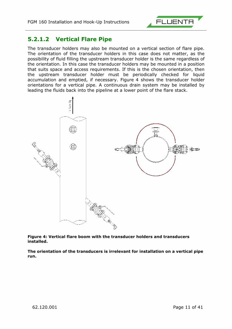
The transducer holders may also be mounted on a vertical section of flare pipe. The orientation of the transducer holders in this case does not matter, as the
possibility of fluid filling the upstream transducer holder is the same regardless of the orientation. In this case the transducer holders may be mounted in a position
that suits space and access requirements. If this is the chosen orientation, then the upstream transducer holder must be periodically checked for liquid accumulation and emptied, if necessary. Figure 4 shows the transducer holder
orientations for a vertical pipe. A continuous drain system may be installed by leading the fluids back into the pipeline at a lower point of the flare stack.
Figure 4: Vertical flare boom with the transducer holders and transducers
installed.
The orientation of the transducers is irrelevant for installation on a vertical pipe
run.
FGM 160 Installation and Hook-Up Instructions
62.120.001 Page 12 of 41
5.2.2 Cold Tapping
Installation of transducer holders must always be supervised by trained Fluenta personnel. Before installing the transducer holders on the pipe, the correct
placement of the spot marks must be ensured. There are numerous ways this can be done.
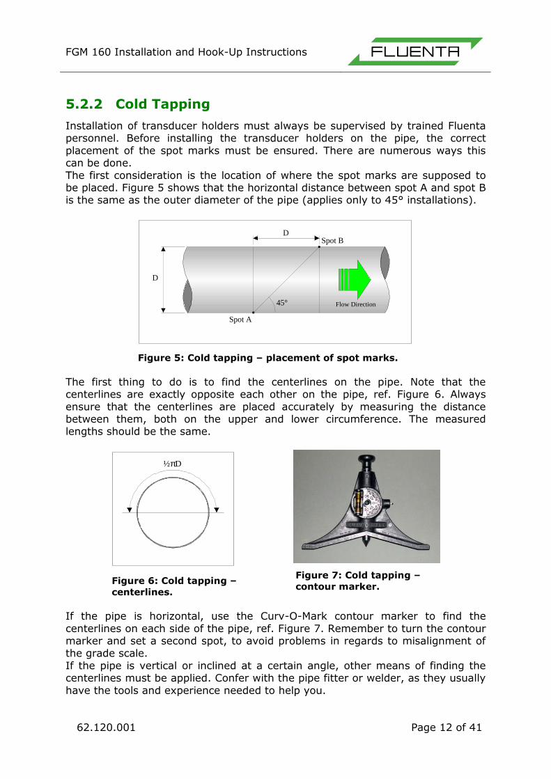
The first consideration is the location of where the spot marks are supposed to be placed. Figure 5 shows that the horizontal distance between spot A and spot B is the same as the outer diameter of the pipe (applies only to 45° installations).
Figure 5: Cold tapping – placement of spot marks.
The first thing to do is to find the centerlines on the pipe. Note that the centerlines are exactly opposite each other on the pipe, ref. Figure 6. Always
ensure that the centerlines are placed accurately by measuring the distance between them, both on the upper and lower circumference. The measured lengths should be the same.
Figure 6: Cold tapping –
centerlines.
Figure 7: Cold tapping –
contour marker.
If the pipe is horizontal, use the Curv-O-Mark contour marker to find the
centerlines on each side of the pipe, ref. Figure 7. Remember to turn the contour marker and set a second spot, to avoid problems in regards to misalignment of the grade scale.
If the pipe is vertical or inclined at a certain angle, other means of finding the centerlines must be applied. Confer with the pipe fitter or welder, as they usually
have the tools and experience needed to help you.
D
D
Spot A
Spot B
Flow Direction45°
½pD

FGM 160 Installation and Hook-Up Instructions
62.120.001 Page 13 of 41
One proven method is to use a marking band. After the centerlines have been marked and their position has been verified, use the labeling band to mark a line
around the pipe, placed at the first spot (spot A), ref. Figure 8. Then, on the other side of the pipe, measure the distance to the second spot (spot B). It is
also a good idea to mark another line around the pipe at spot B, as this will help when placing transducer holder B.
Figure 8: Marking a line around the pipe using a marking band.
Mark the hole for the sensors on the pipe wall following the inside rim of the
transducer holder when they are mounted in the welding-jig. Repeat the procedure for the other transducer holder. The holes can now be cut according to
the marked line on the pipe-wall. After the holes are cut, ensure that the inner edges are grinded to be smooth, and beveled in the correct way, ref. Figure 9. Before the welding starts, the
groove angle must be grinded on the holders. Normally the holders must be taken off the welding-jigs for grinding/adjustment to get the right opening and
joint, ref. Figure 10.
Spot A
πD

FGM 160 Installation and Hook-Up Instructions
62.120.001 Page 14 of 41
Figure 9: Machined hole.
Figure 10: Machined holder.
Adjust the gap between the pipe and the transducer holder until it is correct. This is done to get a satisfactory welding connection. Usually, the spacing will be
between 2mm and 4mm, depending on the welder’s preference, but always at the correct angle (45º/48º/42). Note that as you raise the transducer holder
from the pipe, it must be moved backwards with the same amount (applies only to 45º installations), see Figure 11.
Figure 11: As you raise the transducer holder, you must also move it backwards
to keep the centering correct.
When the transducer holders are grinded and the holes have been made, the welding-jig should be located in the right position and the transducer holder
connected. The transducer holder can now be tacked to the pipe. Usually, the welder will use three or four tacks. Ensure that there is enough space to insert
the transducer. Fluenta recommends using the sighting tool to verify this. The tool should be able to be inserted without any friction or obstructions. The next step is to mount the second transducer holder. Repeat the procedure,
but to verify the exact location/position, you must use the special measuring/view tool.
It is assumed that the buyer’s welding procedure is approved before the work starts and that the welding is performed by certified welders.

FGM 160 Installation and Hook-Up Instructions
62.120.001 Page 15 of 41
When correct alignment of both transducer holders is ensured (see section 0), the welder can weld and fill out both transducer holders. Be aware that as the
welding is in progress, the transducer holders can be pulled off their angles by the welding process. Therefore, it is necessary to pay close attention during the
welding, regularly checking the angles with the digital electronic level.
Figure 12: Welding jig and
transducer holder.
Figure 13: Transducer holder welded to
the pipe.
This activity needs to be carried out by a skilled welder as precision and accuracy
is necessary to get the transducer holders welded into their right positions. The transducer holders are welded onto the pipe according to the buyer’s welding
procedure. Next step will be NDT and final approval of the welding. The welding-jigs can be dismounted when the transducer holders are properly connected to the pipe as shown in Figure 13.

FGM 160 Installation and Hook-Up Instructions
62.120.001 Page 16 of 41
5.2.3 Using the Sighting Tool
There are two types of sighting tool, one for each angle set. The first type, shown in Figure 15, is for transducer holders mounted at a 45° angle. There are
two tools in a set, one fits tightly in each transducer holder. Each of the tools has a hole in the center.
Figure 14:
The sighting
tool for the
42°/48°
transducer
holders
Figure 15: The sighting tool
for 45° transducer holders.
Figure 16: The
stop washer for
the sighting tool
for the 42°/48°
transducer
holders.
The second type of sighting tool is made for transducer holders that are mounted on pipes with a diameter of 10” and less and with 42°/48° transducer holders, ref. Figure 14. This set of tools uses the path of light for verification like the first.
As the transducer holder’s mounting angles are not equal, these tools require some adjustments before they can be used. The set comes with a pair of stop
washers, shown in Figure 16. The tool must penetrate the transducer holder to the same depth as the transducer.
Figure 17: A 45° sighting
tool mounted in a transducer holder.
Figure 18: A 42°/48° sighting tool with
stop washer mounted in a transducer holder.

FGM 160 Installation and Hook-Up Instructions
62.120.001 Page 17 of 41
When using the sighting tool for pipes that have a diameter greater than 10”, insert the sighting tool into the transducer holder so that the flange of the
sighting tool is flush with the flange of the transducer holder. This is shown in Figure 17.
When using the sighting tool for pipes that are 10” and less, use the measurement from the special tool as described in section 5.3.1 to find the correct depth for the transducer. This depth should be the same for the sighting
tool. Measure from the narrow end of the sighting tool and tighten the stop washer at that position. Insert the sighting tool so that the stop washer is flush
with the flange on the transducer holder, this is shown in Figure 18. There is a groove in the head of this type of sighting tool shown in Figure 19. Align one sighting tool with the pipe, and rotate the other until the light is visible. Adjust
the sensor holder so that the circle of light is seen as described below.
Figure 19: Look through the holes on the sighting tool. Rotate the sighting tool
on the left to get a correct alignment.
When the transducer holders are properly aligned and the sighting tools are
inserted, it is possible to see a perfect circle of light when looking through the hole in one of the sighting tools, shown in Figure 20. If there is not enough
ambient light, it may be necessary to shine a light source through the hole in the opposite sighting tool.
Visual check

FGM 160 Installation and Hook-Up Instructions
62.120.001 Page 18 of 41
Figure 20: A good alignment.
Figure 21: A bad alignment.
5.2.4 Hot Tapping Transducers Full Size, TFS
If hot tapping is needed, use the same procedure as described in “Cold Tapping”
but do not drill the pilot holes. When the welding of the transducer holders has been performed and the ball valves are mounted, connect the hot-tapping equipment to the 2" ball valve. Open the ball valve and drill the hole. The hole
should be as close to 49.3 mm as possible, but care should be taken to avoid damage to the ball valve. If possible, use a 49 mm drill and avoid sharp edges.
5.3 Mounting the Ultrasonic Transducers
5.3.1 Determining the Correct Position for the
Transducers
Fluenta will use a special gas proof measuring tool to find the correct position for the transducers, as shown in Figure 22. The method is shown in the figure below.
This is carried out on site during installation of the transducers due to the fact that the entire length is measured, including ball valves and gaskets. The transducer is thereafter positioned correctly.
Figure 22: The gas-proof measuring tool.

FGM 160 Installation and Hook-Up Instructions
62.120.001 Page 19 of 41
Figure 23: A schematic of the gas-proof measuring tool.
5.3.2 Edge Flush Transducer Mounting
5.3.2.1 Setting the correct insertion depth
The insertion depth measurement should be performed as usual. When setting the insertion depth, remember that the retraction of the transducer means that
the insertion depth should be reduced (see Figure 24).
Figure 24: Insertion depth.
The insertion depth (green arrow) must be reduced (red arrow) according to the angle of the transducer holder
As a result of the reduced insertion depth, the distance between the transducer tips will increase (see Figure 25). The transducer tip distance is a parameter that
directly affects the flow velocity calculations, therefore the transducer distance must be updated in the configuration of the flow computer.
For the FGM 160, the transducer distance can be found in the O&S Console software under Config – Config Main Page – Mechanical Parameters – Measured (length in m).

FGM 160 Installation and Hook-Up Instructions
62.120.001 Page 20 of 41
Figure 25: Retracted tranducers distance.
When the transducers are retracted, the transducer distance will increase from
the original distance (red arrow in Figure 25) to the new transducer distance (green arrow). This must be updated in the flow computer.
5.3.2.2 45° installations
Figure 26: Edge-flush position for a 45° transducer holder.
For an installation where the transducer-holder angles are 45°, the retraction
needed for each transducer is 18mm (see Figure 26). The transducer distance must then be increased by 36mm (2x18mm) in the flow computer configuration.
FGM 160 Installation and Hook-Up Instructions
62.120.001 Page 21 of 41
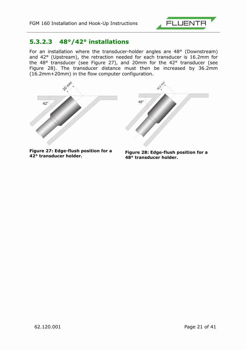
5.3.2.3 48°/42° installations
For an installation where the transducer-holder angles are 48° (Downstream) and 42° (Upstream), the retraction needed for each transducer is 16.2mm for
the 48° transducer (see Figure 27), and 20mm for the 42° transducer (see Figure 28). The transducer distance must then be increased by 36.2mm
(16.2mm+20mm) in the flow computer configuration.
Figure 27: Edge-flush position for a
42° transducer holder.
Figure 28: Edge-flush position for a
48° transducer holder.

FGM 160 Installation and Hook-Up Instructions
62.120.001 Page 22 of 41
5.3.3 Insertion of the Transducer Full Size (TFS)
When the transducer holders and ball valves are installed, the ultrasonic transducers may be inserted. This shall ONLY be done by personnel certified by
Fluenta. If this is a first time installation, the transducer holder should be checked for liquid and drained prior to installation. Care must be taken to avoid
any impact or friction to the ultrasonic sensor head. Also, it must be ensured that the sensor casing is connected to protective earth.
NOTE: During transducer installation, the power supply to FGM 160 must
be turned OFF!
Verify that the installed ball valves are gas tight (no gas leaks). This should be done by the on-site personnel - using a gas monitoring device. Measure and
adjust the installation depth of each transducer, which is set by fastening the A-lock lock-ring. Mount the transducer/packbox. Open the ball valve, and push the
transducer all the way in, until meeting the A-lock locker ring. Fasten the A-lock nut to the transducer packbox.
Figure 29: Mounting the Transducer Full Size.
6. FIELD COMPUTER INSTALLATION
In order to reduce signal loss and maintain signal quality, the length of the signal
cables should be kept as short as possible. Thus the FGM 160 (Ex-d/e Enclosure) must be mounted close to the spool piece/ transducers. The FGM 160 has lugs that enable easy mounting on either a separate frame or on top of the spool
piece by brackets.
6.1 The Field Computer Mounting Frame
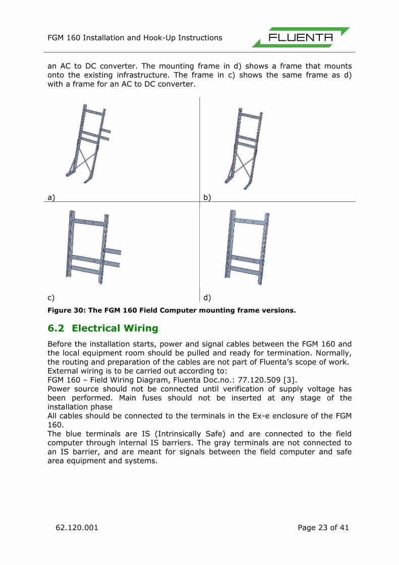
The field computer can be mounted on existing infrastructure, or a custom
mounting frame. The custom mounting frame comes in four versions. The first is shown in Figure 30 a), and includes legs for a free standing mount, as well as
two frames for mounting a separate AC to DC converter in an Ex-d housing. The frame shown in b) is the same, except it does not include a mounting frame for
Insert the transducer
2 Open the ball valve
3
Mount the transducer
Screw in the locking nut
1
4
FGM 160 Installation and Hook-Up Instructions
62.120.001 Page 23 of 41
an AC to DC converter. The mounting frame in d) shows a frame that mounts onto the existing infrastructure. The frame in c) shows the same frame as d)
with a frame for an AC to DC converter.
a) b)
c) d)
Figure 30: The FGM 160 Field Computer mounting frame versions.
6.2 Electrical Wiring
Before the installation starts, power and signal cables between the FGM 160 and the local equipment room should be pulled and ready for termination. Normally,
the routing and preparation of the cables are not part of Fluenta’s scope of work. External wiring is to be carried out according to:
FGM 160 – Field Wiring Diagram, Fluenta Doc.no.: 77.120.509 [3]. Power source should not be connected until verification of supply voltage has been performed. Main fuses should not be inserted at any stage of the
installation phase All cables should be connected to the terminals in the Ex-e enclosure of the FGM
160. The blue terminals are IS (Intrinsically Safe) and are connected to the field computer through internal IS barriers. The gray terminals are not connected to
an IS barrier, and are meant for signals between the field computer and safe area equipment and systems.

FGM 160 Installation and Hook-Up Instructions
62.120.001 Page 24 of 41
Figure 31: Ex-e enclosure terminals overview.
Note: Foundation Fieldbus terminal overview available in doc. no. 77.120.217.
6.2.1 Cable Preparations
The steps described below should be carried out at both ends of the cables. However, the installation of glands is not applicable for the Local Equipment Room.
• Verify the labeling/tag name on the cable. • Verify whether the cable is “megged” or not.
• Cut the cable to a length that allows slack. • Pull the cable through its respective gland, and make sure that the
cable gland is of the required type and size.
• Terminate and secure the cable and cable gland according to instructions for the specific cable gland.
• Strip and terminate the conductors and screen according to good workmanship.
• If the cable is not “megged”, it should be carried out at this point.
• The conductors and screens should also be checked for continuity.

FGM 160 Installation and Hook-Up Instructions
62.120.001 Page 25 of 41
6.2.2 Power Cable
The FGM 160 requires a 24 VDC power supply (ref. section 4.3 Equipment Information). Keep the twisting of the conductor pair and route the conductors to
the power input terminals (ref. Figure 31). If applicable, terminate the screen to the PE Earthbar.
Figure 32: Power to the FGM 160.
NOTE: It is forbidden to energize the computer without a properly trained
personnel to supervise it. Certified personnel include Fluenta service engineers, service engineers of our agents who have received proper training and operators who have attended and completed Fluenta’s
2-day Operators Training Course. Energizing the computer without Fluenta certified personnel will cause loss of warranty.
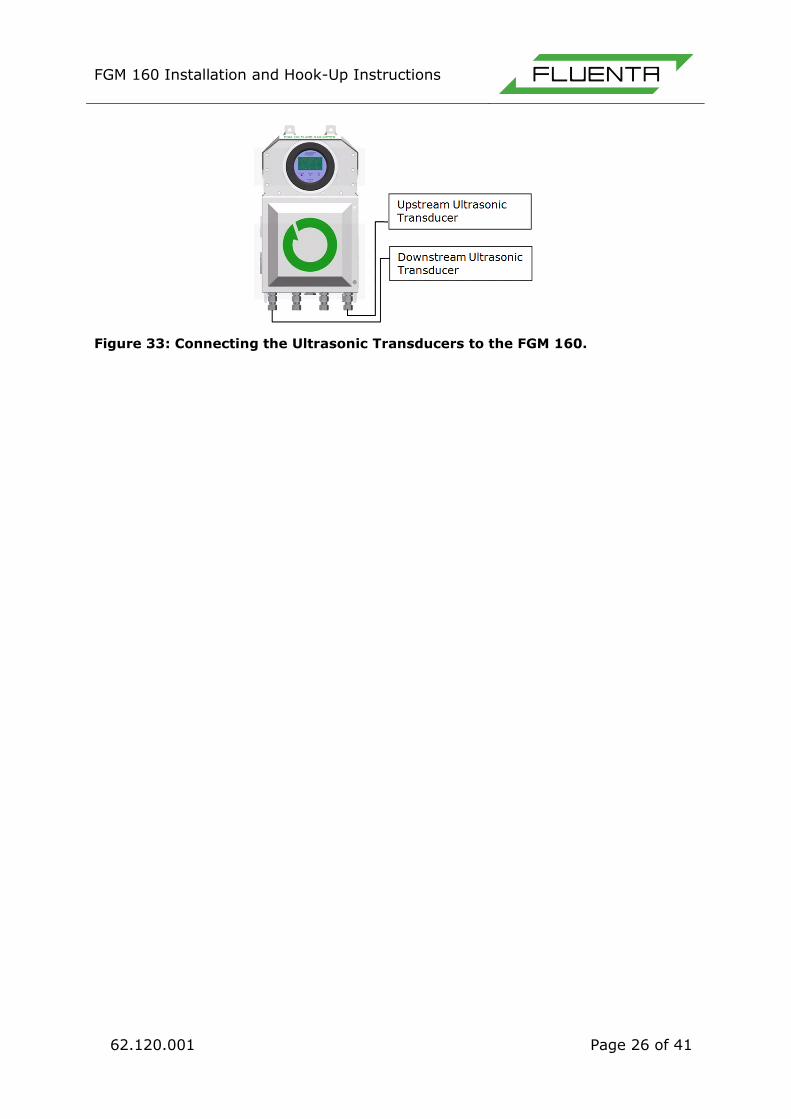
6.2.3 Ultrasonic Transducer Cables
The ultrasonic transducer cables are already prepared at the Fluenta production
facilities. These cables should be handled with care. Verify the labeling/tag name on the cable. Pull the cable through its respective gland; make sure that the cable gland is of the required type and size. Secure
the cable and cable gland. It is recommended that the cable between the FGM and the transducers is kept
as short as possible, 10 meter cable is supplied as a standard. For other lengths than standard, Fluenta must be notified.
FGM 160 Installation and Hook-Up Instructions
62.120.001 Page 26 of 41
Figure 33: Connecting the Ultrasonic Transducers to the FGM 160.
FGM 160 Installation and Hook-Up Instructions
62.120.001 Page 27 of 41
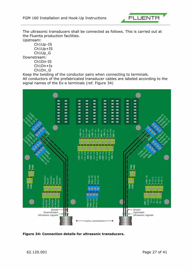
The ultrasonic transducers shall be connected as follows. This is carried out at the Fluenta production facilities.
Upstream: Ch1Up–IS
Ch1Up+IS Ch1Up_G Downstream:
Ch1Dn-IS Ch1Dn+Is
Ch1Dn_G Keep the twisting of the conductor pairs when connecting to terminals. All conductors of the prefabricated transducer cables are labeled according to the
signal names of the Ex-e terminals (ref. Figure 34)
Figure 34: Connection details for ultrasonic transducers.

FGM 160 Installation and Hook-Up Instructions
62.120.001 Page 28 of 41
6.2.4 Connecting the Pressure and Temperature
Transmitters
Pressure and temperature transmitters should be connected directly to the
connection terminals in the Ex-e enclosure, no barriers are required, as these are built-in in the IS Barrier module within the FGM 160. For detailed information regarding the built-in barriers and the optional grounding wire shown in Figure
35, please refer to: FGM 160 – Hazardous Area Installation Guidelines [2]. The FGM 160 can interface either to 4-20 mA current loop transmitters or HART
transmitters. Depending on the transmitter interface to the FGM 160, a connection described in figures below should be used. Up to four HART transmitters can be connected to the HART input terminals, e.g. if condition
based maintenance scheme is utilized with double or dual transmitters. The pressure and temperature inputs at the FGM 160 are always configured as
active current loop inputs (i.e. the pressure and temperature transmitters are always powered from the FGM 160 field computer).
Figure 35: Pressure and temperature transmitter hook-up.

FGM 160 Installation and Hook-Up Instructions
62.120.001 Page 29 of 41
Figure 36: FGM 160 – 4-20 mA pressure and temperature transmitter
connections.
Figure 37: Pressure and Temperature HART transmitter connection.

FGM 160 Installation and Hook-Up Instructions
62.120.001 Page 30 of 41
6.2.5 Control Room and Data Cables
The FGM 160 Flow Computer can be connected to the control room in several different ways. These allow the DCS or SCADA software in the control room to
communicate with the FGM 160 Flow Computer. The connection options are as follows:
• DCS port, Modbus protocol (RS-485) • Three (3) 4-20 mA, with additional three (3) as option. • HART interface (optional).
• One (1) Pulse, Frequency or Level output (optional).
Figure 38: Data and Signal Cables.
The Service port is for the Operator & Service Console. This connection must
be available in the safe area in order to enable Fluenta support personnel to check the meter’s performance, configure the meter and upload new firmware.
Figure 38 shows the different connections. Normally, Operator Console and DCS wiring is not a part of Fluenta’s scope of work.
6.2.5.1 DCS Port, Modbus
The FGM 160 can be interfaced to a DCS Modbus system by an RS 485 signal
interface. Normally a 2-wire interface is used, but 4-wire interface can also be used.
For detailed information regarding the DCS port wiring, please refer to: FGM 160 – DCS Modbus Interface Specifications [4]. DCS Modbus Interface is disabled in FGM 160 Foundation Fieldbus configuration
6.2.5.2 Foundation Fieldbus Output
In FGM 160, FF configuration 4-20mA Outputs are not available. They are replaced by Foundation Fieldbus Outputs. Wires for FF should be connected to
FF_1 and FF_2 outputs marked on the Figure below.

FGM 160 Installation and Hook-Up Instructions
62.120.001 Page 31 of 41
Figure 39: Foundation Fieldbus Connection
6.2.5.3 Service Port
The wiring of the service port is similar to the DCS port wiring. For more detailed information, please refer to: FGM 160 – Operator Console
Description [5].
6.2.5.4 Current Loop Outputs (4-20mA)
The FGM 160 has three operational 4-20mA current loop outputs as default, with
additional three as an option. Each of the current loop outputs can be configured either as active or passive output.
In active output configuration, the current loop is powered from the FGM 160 field computer. In passive output configuration, an external power source is
required. In default configuration, all current loop outputs are configured as active outputs. The current loop outputs can be configured as follows:
Analog output. o The output is assigned to a specific parameter/process variable and
configured with a desired range. Alarm status output.
o The output can be configured as a specific alarm output (e.g.
temperature alarm) or as a general global alarm output. o Alarm level can be set to 4mA or 20mA.
Level indicator output. o The output can be configured to shift from 4mA to 20mA (or
opposite) at a certain level of the assigned variable.
Current Loop Outputs are replaced by Foundation Fieldbus Outputs in FGM 160 Foundation Fieldbus configuration.
FGM 160 Installation and Hook-Up Instructions
62.120.001 Page 32 of 41
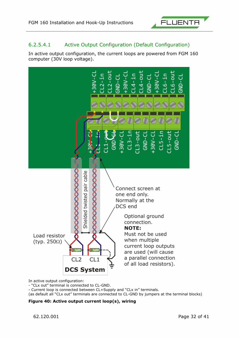
6.2.5.4.1 Active Output Configuration (Default Configuration)
In active output configuration, the current loops are powered from FGM 160 computer (30V loop voltage).
In active output configuration: - “CLx out” terminal is connected to CL-GND. - Current loop is connected between CL+Supply and “CLx in” terminals. (as default all “CLx out” terminals are connected to CL-GND by jumpers at the terminal blocks)
Figure 40: Active output current loop(s), wiring
FGM 160 Installation and Hook-Up Instructions
62.120.001 Page 33 of 41
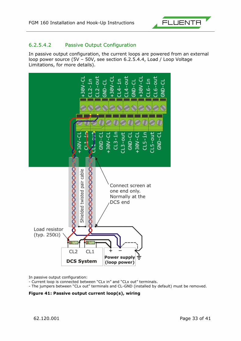
6.2.5.4.2 Passive Output Configuration
In passive output configuration, the current loops are powered from an external loop power source (5V – 50V, see section 6.2.5.4.4, Load / Loop Voltage
Limitations, for more details).
In passive output configuration:
- Current loop is connected between “CLx in” and “CLx out” terminals. - The jumpers between “CLx out” terminals and CL-GND (installed by default) must be removed.
Figure 41: Passive output current loop(s), wiring

FGM 160 Installation and Hook-Up Instructions
62.120.001 Page 34 of 41
6.2.5.4.3 Current Loop Outputs Details
The current loop outputs of the FGM 160 are galvanic isolated from the rest of the FGM 160
field computer. However, they are not individually isolated with respect to each other (they all share the same
ground reference point). The outputs are protected against reverse
polarity. See Figure 42 for detailed schematic of the current loop outputs.
6.2.5.4.4 Load / Loop Voltage
Limitations
A typical load resistor value is 250Ω.
This value gives a voltage on the DCS input within the range of 1 – 5V.
Active Output Configuration In active output configuration, the loop voltage is 30V.
Minimum loop resistance: 100Ω. Maximum loop resistance: 1350Ω.
Passive Output Configuration Minimum loop voltage: 5V. Maximum loop voltage: 50V.
Minimum loop resistance: - Loop voltage < 30V: Rloop min. = 100Ω.
- Loop voltage > 30V: Rloop min. = (Loop voltage - 28V) x 50 [Ω]. Maximum loop resistance:
Rloop max. = (Loop voltage - 3V) x 50 [Ω].
Table 2: Min./max. loop resistance at typical
loop voltages.
Loop voltage Rloop
min.
Rloop
max.
12 V 100 Ω 450 Ω
24 V 100 Ω 1050 Ω
30 V 100 Ω 1350 Ω
36 V 400 Ω 1650 Ω
48 V 1000 Ω 2250 Ω Figure 42: Current loop
outputs, details

FGM 160 Installation and Hook-Up Instructions
62.120.001 Page 35 of 41
Figure 43: Current loop outputs, Load/Voltage limitations
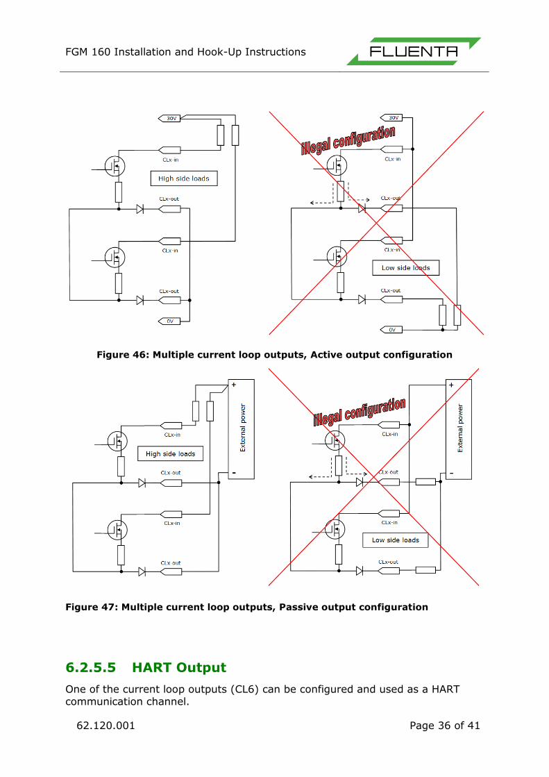
6.2.5.4.5 Restrictions of the Current Loop Outputs
High side load/Low side load The load resistor should normally be connected on high side (see Figure 44 and Figure 45). Low side load can be used alternatively, but only when a single
current loop outputs is used/connected. If more than one current loop output is used and load resistor is connected on low side, the readings on each output will
show erroneous values. The reason for this is that the current from each output will disperse over all connected outputs. (see Figure 46 and Figure 47)
Figure 44: Current loop active output, High side load and Low side load
Figure 45: Current loop passive output, High side load and Low side load
FGM 160 Installation and Hook-Up Instructions
62.120.001 Page 36 of 41
Figure 46: Multiple current loop outputs, Active output configuration
Figure 47: Multiple current loop outputs, Passive output configuration
6.2.5.5 HART Output
One of the current loop outputs (CL6) can be configured and used as a HART communication channel.
FGM 160 Installation and Hook-Up Instructions
62.120.001 Page 37 of 41
For detailed information regarding wiring of the HART output channel, please refer to: FGM 160 – HART Output Interface Specification [6].
6.2.5.6 Pulse/Frequency/Level Output
As an option, the FGM 160 can be configured with one passive pulse/frequency/level output.
This output can be configured in three different ways: Pulse output configuration.
o The pulse signal can be used e.g. to interface an external
totalizer/counter. Frequency output configuration.
o The frequency signal can be used as an alternative to analog current loop output.
Level output configuration. o This signal can e.g. be used for alarm or status output.

FGM 160 Installation and Hook-Up Instructions
62.120.001 Page 38 of 41
6.2.5.6.1 Voltage / Current Limitations
Maximum voltage: 30V Maximum current: 40 mA (output is protected by a 62mA internal fuse)
Figure 48: FGM 160 Pulse/frequency output connections
Figure 49: FGM 160 Pulse/frequency output connections. Without external
power

FGM 160 Installation and Hook-Up Instructions
62.120.001 Page 39 of 41
6.3 Upgrading from the FGM 130
It is strongly recommended to upgrade all FGM 130 installations to FGM 160. The upgrade is relatively simple and easy to perform. Existing mounts can be used,
although the transducers must be replaced, as the FGM 160 uses upgraded Ultrasonic Transducers, and the signal is not backward compatible with the
Ultrasonic Transducers used with the FGM 130. The existing temperature and pressure sensors can be used, and the fiber optic cables can be re-used for DCS signal transmission with the addition of an RS485 optical converter. The figure
below shows the similarities and differences between the FGM 130 and FGM 160 setups.
Figure 50: FGM 130 –> FGM 160 upgrade

FGM 160 Installation and Hook-Up Instructions
62.120.001 Page 40 of 41
The table below shows the components of the FGM 130 that can be re-used when upgrading to the FGM 160.
FGM 130
FGM 160
Flow Computer No Replaced by FGM 160 Computer
Field Electronics Enclosure No Integrated in FGM 160 Computer
Ultrasonic Sensors No New FGM 160 sensors
Pressure Transmitter Yes Interface directly to FGM 160 Computer
Temperature Transmitter Yes Interface directly to FGM 160
Computer
Power Cable Yes Power or Communication
Fiber Optic Signal Cable Yes Communication (RS422/RS485)
Sensor Holders Yes
DCS/SCADA Interface Yes Compatible, with an additional HART interface
7. REFERENCES
[1] FGM 160 – Preservation, Packing, Unpacking and Storage Procedure [2] FGM 160 – Hazardous Area Installation Guidelines
[3] FGM 160 – Field Wiring Diagram, Fluenta Doc.no.: 77.120.509 [4] FGM 160 – DCS Modbus Interface Specifications [5] FGM 160 – Operator Console Description
[6] FGM 160 – HART Output Interface Specification

FGM 160 Installation and Hook-Up Instructions
62.120.001 Page 41 of 41
8. APPENDIX I - SPACE REQUIREMENTS FOR
THE TFS
Figure 51: Space requirements for the TFS


![A Comparison of Floating Point and Logarithmic Number ... · 3 Number Systems 3.1 Floating point A floating point number F has the value [Koren02] F =−1S ×1. f ×2E where S is](https://img.pdfslide.net/doc/110x75/5f1bbfe83ee80a7be934a382/a-comparison-of-floating-point-and-logarithmic-number-3-number-systems-31-floating.jpg)