Embed Size (px)
Citation preview
ED 404 840
TITLE
INSTITUTIONPUB DATENOTEAVAILABLE FROM
PUB TYPE
EDRS PRICEDESCRIPTORS
DOCUMENT RESUME
EC 305 440
Standing on My Own Two Feet: A Step-by-Step Guide toDesigning & Constructing Simple, IndividuallyTailored Adaptive Mobility Devices for Preschool-AgeChildren Who Are Visually Impaired.Blind Childrens Center, Los Angeles, CA.96
41p.
Blind Children's Center, 4120 Marathon Street, LosAngeles, CA 90029; telephone: 800-222-3566; fax:212-665-3828; e-mail: [email protected] ($8).Books (010) Guides Non-Classroom Use (055)
MF01/PCO2 Plus Postage.Assistive Devices (for Disabled); Case Studies;*Construction (Process); Construction Materials;*Mobility Aids; Personal Autonomy; PreschoolChildren; *Visual Impairments; *Visually ImpairedMobility
IDENTIFIERS Canes; *Orienting Instruction
ABSTRACTThis booklet provides step-by-step instructions for
designing and constructing simple, individually tailored adaptivemobility devices for preschool-age children who are visuallyimpaired. These devices are intended to enable children to begin tomaster independent travel, which'precedes long cane training. How tointroduce the mobility device to children, why an adaptive mobilitydevice is needed, how to determine the appropriate device, andtypical sequencing and device transition are discussed. Fourdifferent types of devices are then introduced: the Moveabout (withthree different design options), the Pusher, the L-Bar, and theArc-Definer. Instructions about each device include a list of thematerials and tools needed to construct the device, the cost ofmaterials and tools, optional features, and construction directions.Information is also provided on how to individualize devices to fitthe height and width of the child, and photographs and diagrams showthe assembly process. Three case studies of children (ages 1-2) withvisual impairments illustrate the use of the devices. (Contains 19references.) (CR)
**************,ti********************************************************
Reproductions supplied by EDRS are the best that can be madefrom the original document.
***********************************************************************

LA,
A
step-by-stepguide to
designing
constructingsimple,
individuallytailoredadaptive
mobility devicesfor preschool-age
childrenwho are
visually impaired
BEST COPY AVAILABLE'
TANDINGON MY
OWNTWO
-:.
V BLIND CHILDRENS CENTER(U S DEPARTMENT OF EDUCATION
Office of Educational Research and ImprovementEDUC IONAL RESOURCES INFORMATION
CENTER (ERIC)his document has been reproduced as
received from the person or organizationoriginating it
Minor changes have been made toimprove reproduction quality.
Points of view or opinions stated in thisdocument do not necessarily representofficial OERI position or policy.
PERMISSION TO REPRODUCE ANDDISSEMINATE THIS MATERIAL
HAS BEEN GRANTED BY
Ark leX"" 5
TO THE EDUCATIONAL RESOURCESINFORMATION CENTER (ERIC)
STANDINGON MY
OWNTWO
FEETA step-by-step guide to designing &
constructing simple, individually
tailored adaptive mobility devices
for preschool-age children
who are visually impaired
by
LORIE LYNN LaPRELLE, M.A.
Blind Childrens Center
Los Angeles, California
3
STANDING ON MY
OWN TWO FEET
A step-by-step guide
to designing and
constructing simple,
individually tailored
adaptive mobility
devices for preschool-
age children who are
visually impaired
All rights reserved.
This is copyrighted
material and may not be
duplicated in whole or in
part without the
express permission of the
Blind Childrens Center.
©1996
Library of Congress
Catalog Card Number
96-085467
Published by
Blind Childrens Center
4120 Marathon Street
Los Angeles
California
90029
(213)664-2153
In California 1(800) 222 -3567
In the USA 1(800) 222 -3566
Fax
(213)665-3828
Web Site
http: / /wwwblindcntr.org /bcc
Photography
Megan Minnehan Smith
Graphic Design & Production
Donna Kaptain
STANDINGON MY
OWNTWO
FEET
A step-by-step guide to designing & constructing simple,individually tailored adaptive mobility devices
for preschool-age children whoare visually impaired
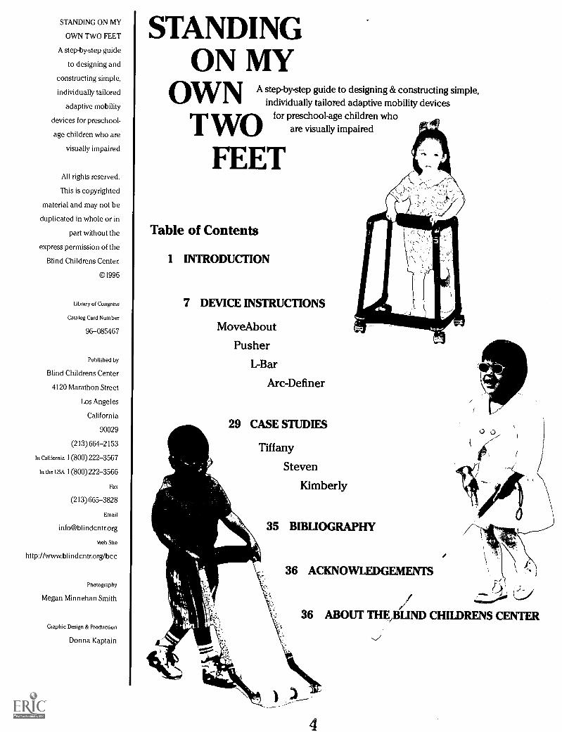
Table of Contents
1 INTRODUCTION
7 DEVICE INSTRUCTIONS
MoveAbout
Pusher
L-Bar
Arc-Definer
29 CASE STUDIES
Tiffany
Steven
Kimberly
35 BIBLIOGRAPHY
36 ACKNOWLEDGEMENTS
Q
/36 ABOUT THE,BLIND CHILDRENS CENTER
4
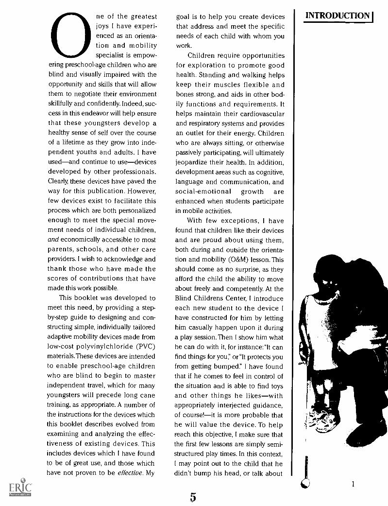
0 ne of the greatestjoys I have experi-enced as an orienta-tion and mobilityspecialist is empow-
ering preschool-age children who areblind and visually impaired with theopportunity and skills that will allowthem to negotiate their environmentskillfully and confidently. Indeed, suc-
cess in this endeavor will help ensurethat these youngsters develop ahealthy sense of self over the courseof a lifetime as they grow into inde-pendent youths and adults. I haveusedand continue to usedevicesdeveloped by other professionals.Clearly, these devices have paved theway for this publication. However,few devices exist to facilitate thisprocess which are both personalizedenough to meet the special move-ment needs of individual children,and economically accessible to mostparents, schools, and other careproviders. I wish to acknowledge andthank those who have made thescores of contributions that havemade this work possible.
This booklet was developed tomeet this need, by providing a step-by-step guide to designing and con-structing simple, individually tailoredadaptive mobility devices made fromlow-cost polyvinylchloride (PVC)materials. These devices are intendedto enable preschool-age childrenwho are blind to begin to masterindependent travel, which for manyyoungsters will precede long canetraining, as appropriate. A number ofthe instructions for the devices whichthis booklet describes evolved fromexamining and analyzing the effec-tiveness of existing devices. Thisincludes devices which I have foundto be of great use, and those whichhave not proven to be effective. My
goal is to help you create devices INTRODUCTIONthat address and meet the specificneeds of each child with whom youwork.
Children require opportunitiesfor exploration to promote goodhealth. Standing and walking helpskeep their muscles flexible andbones strong, and aids in other bod-ily functions and requirements. Ithelps maintain their cardiovascularand respiratory systems and providesan outlet for their energy. Childrenwho are always sitting, or otherwisepassively participating, will ultimatelyjeopardize their health. In addition,development areas such as cognitive,language and communication, andsocial-emotional growth areenhanced when students participatein mobile activities.
With few exceptions, I havefound that children like their devicesand are proud about using them,both during and outside the orienta-tion and mobility (O&M) lesson. Thisshould come as no surprise, as theyafford the child the ability to moveabout freely and competently. At theBlind Childrens Center, I introduceeach new student to the device Ihave constructed for him by lettinghim casually happen upon it duringa play session. Then I show him whathe can do with it, for instance:"It canfind things for you," or"It protects you
from getting bumped:' I have foundthat if he comes to feel in control ofthe situation and is able to find toysand other things he likeswithappropriately interjected guidance,of course!it is more probable thathe will value the device. To helpreach this objective, I make sure thatthe first few lessons are simply semi-structured play times. In this context,I may point out to the child that hedidn't bump his head, or talk about
51
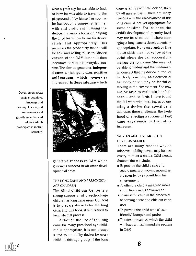
Development areas
such as cognitive,
language and
communication, and
social-emotional
growth are enhanced
when students
participate in mobile
activities.
2
what a great toy he was able to find,or how he was able to travel to theplayground all by himself. As soon as
he has become somewhat familiarwith and proficient in using thedevice, my lessons focus on helpingthe child learn how to use his devicesafely and appropriately. Thisincreases the probability that he willbe able and willing to use the deviceoutside of the O&M lesson. It thenbecomes part of his everyday rou-tine. The device generates indepen-dence which generates positiveself-esteem which generatesincreased independence which
°i
generates success in O&M whichgenerates success in all other devel-opmental areas.
THE LONG CANE AND PRESCHOOL-
AGE CHILDREN
The Blind Childrens Center is astrong supporter of preschool-agechildren as long cane users. Our goalis to prepare students for the longcane, and this booklet is designed tofacilitate that process.
Although the use of the longcane for many preschool-age child-ren is appropriate, it is not alwayssuited as a mobility device for everychild in this age group. If the long
cane is an appropriate device, thenby all means, use it! There are manyreasons why the employment of thelong cane is not yet appropriate forsome children. For instance, thechild's developmental maturity levelmay not be at the point where man-aging a long cane is developmentallyappropriate. Her gross and/or finemotor skills may not yet be at thepoint where she can successfullymanage the long cane. She may notbe able to understand the fundamen-tal concept that the device in front ofher body is actually an extension ofher body, or she may be fearful ofmoving in the environment. She maynot be able to maintain her bal-ance... and so forth. I have foundthat if I work with these issues by cre-ating a device that specificallyaddresses these challenges, the likeli-hood of effecting a successful longcane experience in the futureincreases.
WHY AN ADAPTIVE MOBILITY
DEVICE IS NEEDED
There are many reasons why anadaptive mobility device may be nec-essary to meet a child's O&M needs.Some of these include:
To provide the child a safe andsecure means of moving around asindependently as possible in hisenvironmentTo offer the child a means to moveabout freely in his environmentTo assist the child in the process ofbecoming a safe and efficient caneuserTo provide the child with a"userfriendly" bumper and probeTo offer a means by which the childwill have almost immediate successin O&M
To assist the child in his ability to
process all relevant sensory infor-mation by reducing and/or elimi-nating his safety and fear concernsTo aid in correcting the child's awk-
ward and atypical gait patterns andpoor postural positioning
Additional benefits from using anadaptive mobility device include
Decreased tactual defensiveness byincreased regular interaction withthe child's various environmentsIncreased contact with peersExpanded interaction with allaspects of the child's environmentTangible, first-hand experience withreal travel situations
DETERMINING THE APPROPRIATE
DEVICE
The main issues to consider whenevaluating the child for an adaptivemobility device are his
Walking or emerging walking skills
Level of fear (or lack of) in moving
Comprehension level of arms/hands as an extension of his bodyUnderstanding of the mobilitydevice as an extension of his body
When the child begins to indi-cate that he is ready to walk (i.e.,pulling up to a standing position,cruising furniture, accepting anoffered hand, or pushing push-typetoys), he may be ready for an adap-tive mobility device. A device caneasily and with little expense be con-structed. It will serve to encouragethe child not only to stand indepen-dently, but also to attempt walkingmovements under safe and secureconditions. Care should always betaken to ensure that the child issteady when using the device, eitherby initially not attaching wheels onthe device or by making sure that an 7
adult steadies the device wheneverthe child is using, or is likely to use,the device. Remember, the goal is toprovide a safe and secure means forthe child to start to move around inhis environment. Therefore, facilitat-ing positive first experiences with thedevice is of the utmost importance.
For a child who is fearful aboutmoving around in his environment, adevice may be constructed thatensures the child's physical safety. Itwill also teach him about his sur-roundings without having to uninten-tionally bump into objects in his pathwith various parts of his body.
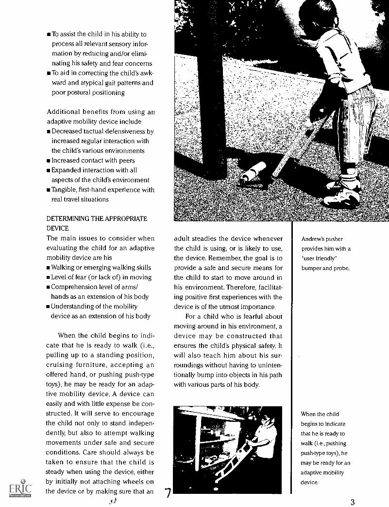
Andrew's pusher
provides him with a
"user friendly"
bumper and probe.
When the child
begins to indicate
that he is ready to
walk (i.e., pushing
push-type toys), he
may be ready for an
adaptive mobility
device.
3

Byron explores his
new Move About.
4
TYPICAL SEQUENCING AND DEVICE
TRANSITION
A child's sequence of device-usebegins with the push-type toys, to theMove About, to the Pusher, to the long
cane (with or without an L-Bar).Oftentimes, children use two differ-ent devices for different purposesand situations. For instance, a childmay keep a Pusher in his classroomto be used for general travel, and bereceiving long cane training duringhis O&M lesson. The amount of timea child uses one device before transi-tioning to another varies from onechild to the next. Unfortunately, thereis no set formula for determining the"what, when, and how" of mobilitydevices.
A Move About is usually themobility device I use as an "introduc-tory" device. In addition to its ease ofuse, the Move About offers nearly fullbody protection. It allows the child toindependently and safely move inthe environment without bumpingwalls and other objects, while realiz-ing the advantages of movement.When the child is comfortable inmoving, is not fearful, understandsthe device as an extension of hisbody, manages and navigates it prop-erly, and is responsible for the useand storage of the device, then it istime to transition to a Pusher.
Unlike the Move About, thePusher requires that the child sup-port the device. In other words, it isnot free-standing. It also requiresmore refined gross motor skills inorder to control and navigate thedevice. It is less cumbersome, butoffers less protection. It adapts touneven surfaces more than theMove About and can be easily man-aged with one hand if needed. Again,once the child starts to indicate thathe is ready for something more chal-
lengingusually indicated by casualemployment of the Pusherit is timeto start formal transition to the longcane.
When the child has long sincebeen introduced to the cane in vari-ous informal situations, it is no longera foreign object. Just like other mobil-
ity devices, the cane is somethingthat is used for safe travel. I usuallydo not attach an L-Bar to the caneunless there is a strong indicationthat the child is not going to be suc-cessful without it. If the child is ableto keep her cane in front of her bodywithout an excess of verbal and phys-ical reminders, an L-Bar is not indi-cated. If, however, the cane is notmaintained in front of her body, thenthe addition of an L-Bar' is needed. Iusually have the child help me makethe device and place it on her cane.Children seem to enjoy this activityand I believe it helps them under-stand the purpose of the L-Bar. Thechild is free to switch hands betweencane grip and L-Bar and can use onlyone hand if she is able to consistentlykeep the cane in front of her body.Decreased use of the L-Bar is a directindicator that it is time to remove itfrom the cane. Sometimes a childwill ask me to take the L-Bar off, atwhich point we talk about "the rules"for using the cane without the L-Bar.With few exceptions, once the deviceis removed, she is able to maintainthe cane in front of her body on aconsistent basis.
Regardless of the type of deviceemployed, the child with whom youare working should be encouragedto bump into walls, doors, and otherlarge objects. Children can evenbump into each other with theirdevices. This can be a great tool forteaching social skills and encourag-ing children to interact with each
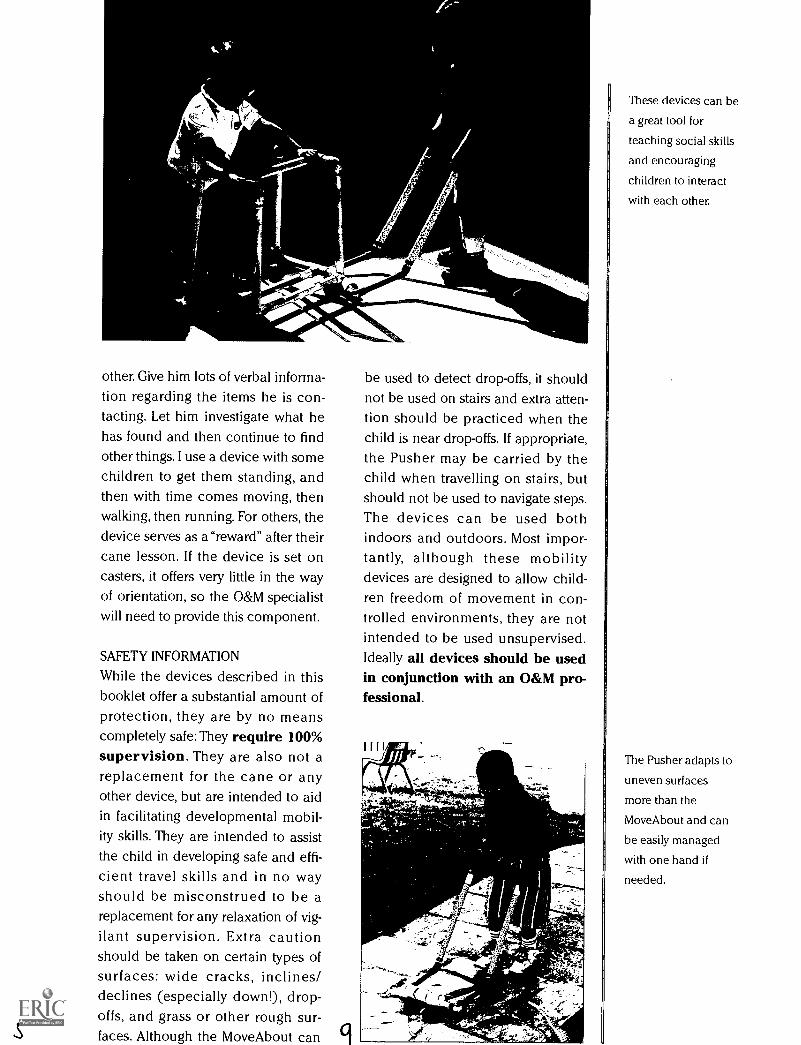
other. Give him lots of verbal informa-
tion regarding the items he is con-tacting. Let him investigate what hehas found and then continue to findother things. I use a device with somechildren to get them standing, andthen with time comes moving, thenwalking, then running. For others, thedevice serves as a "reward" after theircane lesson. If the device is set oncasters, it offers very little in the wayof orientation, so the O&M specialistwill need to provide this component.
SAFETY INFORMATION
While the devices described in thisbooklet offer a substantial amount ofprotection, they are by no meanscompletely safe: They require 100%supervision. They are also not areplacement for the cane or anyother device, but are intended to aidin facilitating developmental mobil-ity skills. They are intended to assistthe child in developing safe and effi-cient travel skills and in no wayshould be misconstrued to be areplacement for any relaxation of vig-ilant supervision. Extra cautionshould be taken on certain types ofsurfaces: wide cracks, inclines/declines (especially down!), drop-offs, and grass or other rough sur-faces. Although the Move About can
be used to detect drop-offs, it shouldnot be used on stairs and extra atten-tion should be practiced when thechild is near drop-offs. If appropriate,the Pusher may be carried by thechild when travelling on stairs, butshould not be used to navigate steps.The devices can be used bothindoors and outdoors. Most impor-tantly, although these mobilitydevices are designed to allow child-ren freedom of movement in con-trolled environments, they are notintended to be used unsupervised.Ideally all devices should be usedin conjunction with an O&M pro-fessional.
41/..
tit
These devices can be
a great tool for
teaching social skills
and encouraging
children to interact
with each other.
The Pusher adapts to
uneven surfaces
more than the
MoveAbout and can
be easily managed
with one hand if
needed.
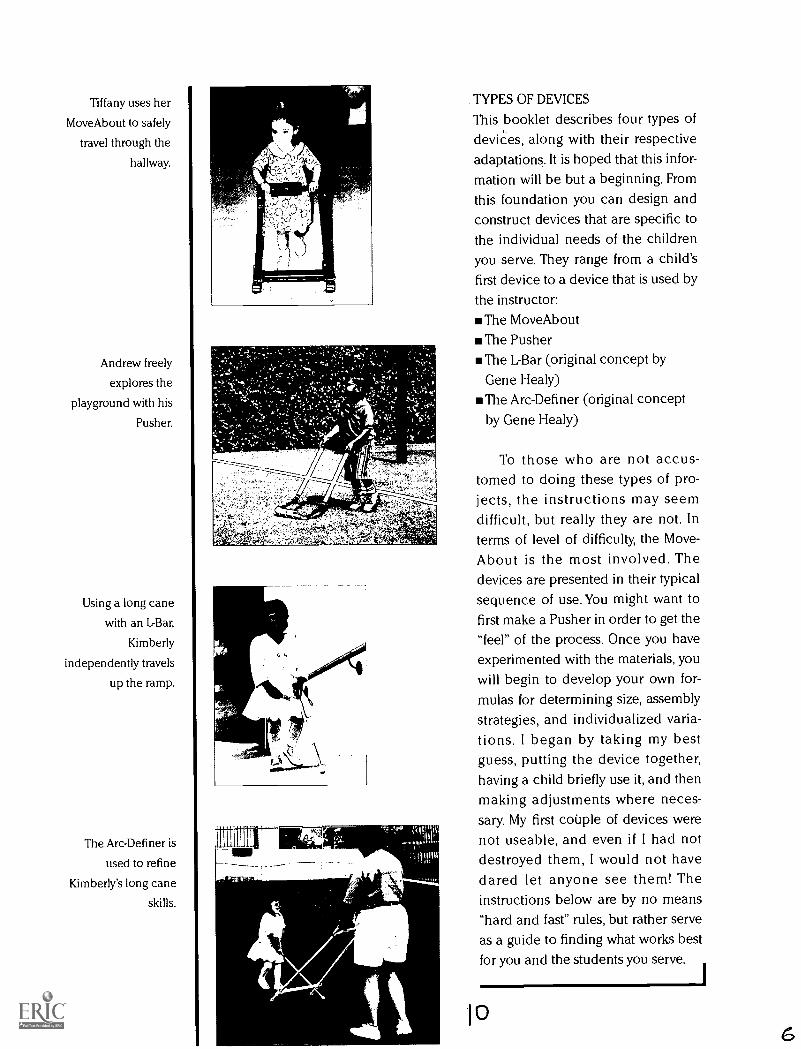
Tiffany uses her
Move About to safely
travel through the
hallway.
Andrew freely
explores the
playground with his
Pusher.
Using a long cane
with an L-Bar,
Kimberly
independently travels
up the ramp.
The Arc-Definer is
used to refine
Kimberly's long cane
skills.
1- .4VIP
TAW
TYPES OF DEVICES
This booklet describes four types ofdevices, along with their respectiveadaptations. It is hoped that this infor-mation will be but a beginning. Fromthis foundation you can design andconstruct devices that are specific tothe individual needs of the childrenyou serve. They range from a child'sfirst device to a device that is used by
the instructor:The Move About
The PusherThe L-Bar (original concept by
Gene Healy)The Arc-Definer (original concept
by Gene Healy)
To those who are not accus-tomed to doing these types of pro-jects, the instructions may seemdifficult, but really they are not. Interms of level of difficulty, the Move-About is the most involved. Thedevices are presented in their typicalsequence of use. You might want tofirst make a Pusher in order to get the"feel" of the process. Once you haveexperimented with the materials, youwill begin to develop your own for-mulas for determining size, assemblystrategies, and individualized varia-tions. I began by taking my bestguess, putting the device together,having a child briefly use it, and thenmaking adjustments where neces-sary. My first couple of devices werenot useable, and even if I had notdestroyed them, I would not havedared let anyone see them! Theinstructions below are by no means"hard and fast" rules, but rather serveas a guide to finding what works bestfor you and the students you serve.
6
Aword about jargon:The terminology usedthroughout theseinstructions utilizes,for the most part,
basic plumbing terms. Although Ihave tried to limit the use of jargon inthese instructions, when you go topurchase materials you will mostassuredly run into the following ter-minology:ELL Elbow jointSOL Side Out Elbow jointTEE Tee joint
S "S" indicates a slip joint (non-threaded)
T "T" indicates a threaded jointSxS Indicates a joint that has fit-
tings that are both slip jointsSxT Indicates a joint that has one
slip fitting and one threadedfitting
SxSxT Indicates a joint that has twoslip fittings and one threadedfitting
Schedule 40 PVC, Schedule 120PVC, etc. The number indicates thedegree of thicknessthe higher thenumber, the thinner the material.
(See the following page for a photoof these materials.)
Size indications and joint types,both on the PVC joints and in theseinstructions, will follow a specific,uniform denotation. For example,unless otherwise indicated, a 1/2" Slipx Slip ELL joint signifies an elbowjoint that is 1/2" on both ends and hasslip fittings at both ends. Similarly, a3/4"x 1/2" Slip x Threaded ELL jointdenotes an elbow joint that is 1/4" onthe slip side and 1/2" on the threadedside. For those of you who are nowcompletely confused, keep reading!Although this seems confusing it willmake sense as you continue.
Although it is not a requirement,marking the pieces with a felt-typepen as you cut them can be veryhelpful. I do this even when I amputting each section together as I amcutting the pieces. This will not onlyreduce unneeded confusion as towhich piece goes where, but will alsohelp ensure success in the assemblyand will further familiarize you withthe various parts of each of thedevices. You can use any terms,abbreviations, or acronyms you wishin order to manage the piecesjustmake sure they make sense to you.Below is a list of the markings I usewhen building the devices. They area bit elaborate, but I have found themuseful.
Possible Abbreviations forLabeling PiecesFLL
FRL
BLL
BRL
TSFL
TSFR
TSBL
TSBR
BSFL
BSFR
BSBL
BSBR
TCB
BCBF
BCBM
Front Left Leg
Front Right LegBack Left Leg
Back Right Leg
Top Side Front Left
Top Side Front Right
Top Side Back Left
Top Side Back Right
Bottom Side Front Left
Bottom Side Front Right
Bottom Side Back LeftBottom Side Back RightTop Cross Bar
Bottom Cross Bar Front
Bottom Cross Bar Middle
Within the instructions for eachof the devices, there are "pre-gluing"and "gluing" instructions. The instruc-tions are divided in this manner inorder to allow for evaluation andexperimentation with the deviceprior to gluing, and to ensure that thedevice will not be put togetherwrong. Since much of "getting it right"comes with experimentation, the pre-
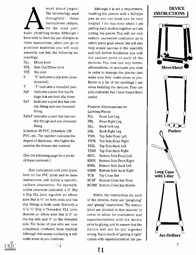
DEVICEINSTRUCTIONS I
MoveAbout
Pusher
Long Canewith L-Bar
Arc-Definer
7
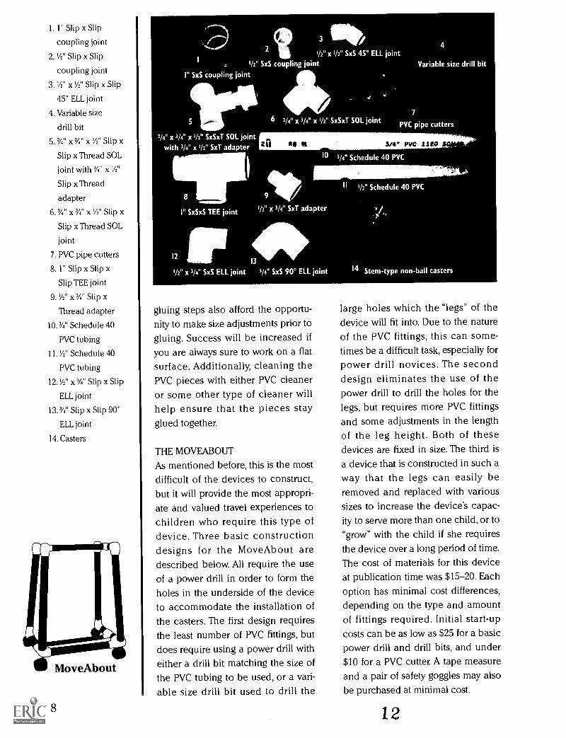
1. 1" Slip x Slip
coupling joint
2. '/2" Slip x Slip
coupling joint
3. 'A" x 'A" Slip x Slip
45° ELL joint
4. Variable size
drill bit
5. N" x 3/4" x 'A" Slip x
Slip x Thread SOL
joint with 3/4" x 'A"
Slip x Thread
adapter
6.3/4" x3/4" x IA" Slip x
Slip x Thread SOL
joint
7. PVC pipe cutters
8. 1" Slip x Slip x
Slip TEE joint
9. 'A" x 3/4" Slip x
Thread adapter
10.3/4" Schedule 40
PVC tubing
11. 'A" Schedule 40
PVC tubing
12.1/2" X 3/4" Slip x Slip
ELL joint
13.3/4" Slip x Slip 90°
ELL joint
14. Casters
MOW
MoveAbout
8
I211
I II
a ti,
gluing steps also afford the opportu-nity to make size adjustments prior togluing. Success will be increased ifyou are always sure to work on a flatsurface. Additionally, cleaning thePVC pieces with either PVC cleaneror some other type of cleaner willhelp ensure that the pieces stayglued together.
THE MOVEABOUT
As mentioned before, this is the mostdifficult of the devices to construct,but it will provide the most appropri-ate and valued travel experiences tochildren who require this type ofdevice. Three basic constructiondesigns for the MoveAbout aredescribed below. All require the useof a power drill in order to form theholes in the underside of the deviceto accommodate the installation ofthe casters. The first design requiresthe least number of PVC fittings, butdoes require using a power drill witheither a drill bit matching the size ofthe PVC tubing to be used, or a vari-able size drill bit used to drill the
II
3/4° PVC 2120
large holes which the "legs" of thedevice will fit into. Due to the natureof the PVC fittings, this can some-times be a difficult task, especially forpower drill novices. The seconddesign eliminates the use of thepower drill to drill the holes for thelegs, but requires more PVC fittingsand some adjustments in the lengthof the leg height. Both of thesedevices are fixed in size. The third isa device that is constructed in such away that the legs can easily beremoved and replaced with varioussizes to increase the device's capac-ity to serve more than one child, or to"grow" with the child if she requiresthe device over a long period of time.The cost of materials for this deviceat publication time was $15-20. Eachoption has minimal cost differences,depending on the type and amountof fittings required. Initial start-upcosts can be as low as $25 for a basicpower drill and drill bits, and under$10 for a PVC cutter. A tape measureand a pair of safety goggles may alsobe purchased at minimal cost.
12
Basic Tools and Materials Neededfor All Three Move About Options
PVC pipe cutters
Power drill
3/8" drill bit
Tape measurePVC glue
Safety goggles
Marking pen
OptionalPadding for top cross bar (foam-
type pipe insulation works great)Spray paint, bicycle handlebarwrap, colored plastic adhesive tape"Channel lock" pliers (optional, butvery helpful!)
Below are sample dimensions foran Option #1 MoveAbout for a two-year-old child who is 30" tall.Measurement from floor-to-elbow is22" and no special adaptations areneeded. If these dimensions areapplied to Option #2, remember todeduct 11/2" from the front legs. If they
are used for Option #3, deduct the11/2" from all four legs. The number of
pieces required is indicated in paren-theses:
Vertical legs are 18" (4 ea.)Top cross bar is 13" (1 ea.)
Bottom cross bars are 15" (2 ea.)Top side pieces are 31/2" (4 ea.)
Front bottom side pieces are 3"(2 ea.)
Rear bottom side pieces are 6"(2 ea.)
Using these dimensions, whenthe device is constructed, includingcasters, it should be approximately22" tall, 141/2" wide (side to side) attop and 161/2" at bottom. It should be10" deep (front to back) at top and13" at bottom.
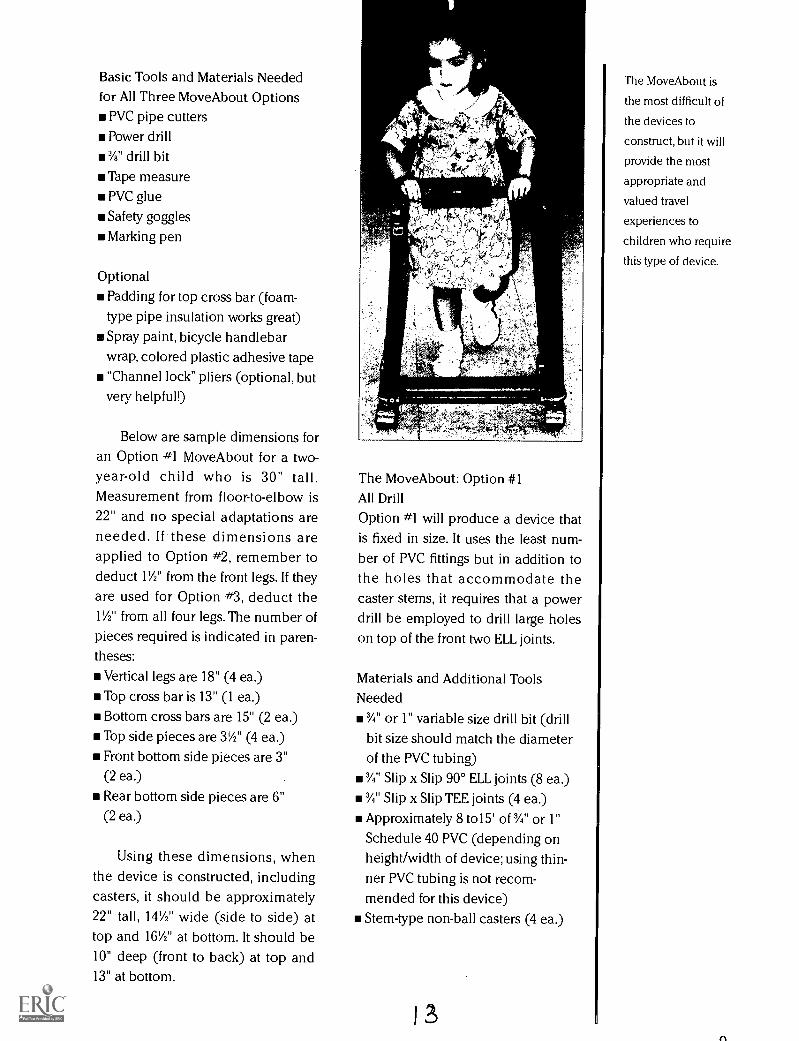
The MoveAbout: Option #1All Drill
Option #1 will produce a device thatis fixed in size. It uses the least num-ber of PVC fittings but in addition tothe holes that accommodate thecaster stems, it requires that a powerdrill be employed to drill large holeson top of the front two ELL joints.
Materials and Additional ToolsNeeded
m3/4" or 1" variable size drill bit (drill
bit size should match the diameterof the PVC tubing)
3/4" Slip x Slip 90° ELL joints (8 ea.)
3/4" Slip x Slip TEE joints (4 ea.)
Approximately 8 to15' of %" or 1"
Schedule 40 PVC (depending onheight/width of device; using thin-ner PVC tubing is not recom-mended for this device)Stem-type non-ball casters (4 ea.)
13
The MoveAbout is
the most difficult of
the devices to
construct, but it will
provide the most
appropriate and
valued travel
experiences to
children who require
this type of device.
fl
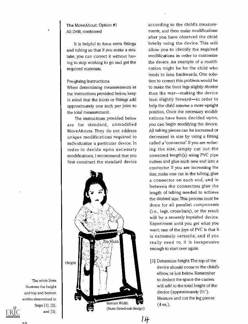
The white lines
illustrate the height
and top and bottom
widths determined in
Steps [1], [2],
and [3].
1
The Move About: Option #1
All Drill, continued
It is helpful to have extra fittingsand tubing so that if you make a mis-take, you can correct it without hav-ing to stop working to go and get therequired materials.
Pre-gluing InstructionsWhen determining measurements inthe instructions provided below, keepin mind that the joints or fittings addapproximately one inch per joint tothe total measurement.
The instructions provided beloware for standard, unmodifiedMoveAbouts. They do not addressunique modifications required toindividualize a particular device. Inorder to decide upon necessarymodifications, I recommend that youfirst construct the standard device
Bottom Width We(Note flared-out design)
/it
according to the child's measure-ments, and then make modificationsafter you have observed the childbriefly using the device. This willallow you to identify the requiredmodifications in order to customizethe device. An example of a modifi-cation might be for the child whotends to lean backwards. One solu-tion to correct this problem would beto make the front legs slightly shorterthan the rearmaking the devicelean slightly forwardin order tohelp the child assume a more uprightposition. Once the necessary modifi-cations have been decided upon,you can begin modifying the device.All tubing pieces can be increased ordecreased in size by using a fittingcalled a"connector." If you are reduc-ing the size, simply cut out theunwanted length(s) using PVC pipecutters and glue each new end into aconnector. If you are increasing thesize, make one cut in the tubing, gluea connector on each end, and inbetween the connectors glue thelength of tubing needed to achievethe desired size. This process must bedone for all parallel components(i.e., legs, cross-bars), or the resultwill be a severely lopsided device.Experiment until you get what youwant; one of the joys of PVC is that itis extremely versatile, and if youreally need to, it is inexpensiveenough to start over again.
[ 1 ] Determine height:The top of thedevice should come to the child'selbow, or just below. Rememberto deduct the space the casterswill add to the total height of thedevice (approximately TA").Measure and cut the leg pieces(4 ea.).
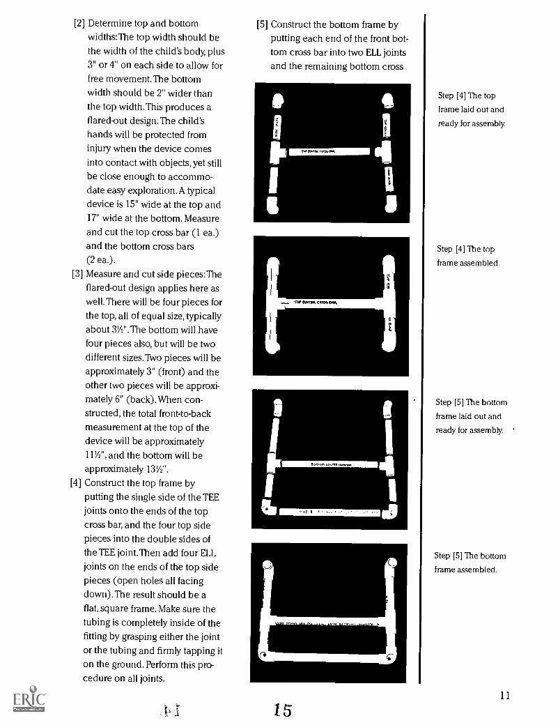
[2] Determine top and bottomwidths:The top width should bethe width of the child's body, plus3" or 4" on each side to allow forfree movement. The bottomwidth should be 2" wider thanthe top width.This produces aflared-out design.The child'shands will be protected frominjury when the device comesinto contact with objects, yet stillbe close enough to accommo-date easy exploration. A typicaldevice is 15" wide at the top and17" wide at the bottom. Measureand cut the top cross bar (1 ea.)and the bottom cross bars(2 ea.).
Measure and cut side pieces:Theflared-out design applies here aswell.There will be four pieces forthe top, all of equal size, typically
about 3V2".The bottom will havefour pieces also, but will be twodifferent sizes. Two pieces will be
approximately 3" (front) and theother two pieces will be approxi-mately 6" (back).When con-structed, the total front-to-back
measurement at the top of thedevice will be approximately111/2", and the bottom will be
approximately 13%2 ".
[4] Construct the top frame byputting the single side of the TEE
joints onto the ends of the topcross bar, and the four top sidepieces into the double sides ofthe TEE joint. Then add four ELL
joints on the ends of the top sidepieces (open holes all facingdown).The result should be aflat, square frame. Make sure the
tubing is completely inside of thefitting by grasping either the jointor the tubing and firmly tapping iton the ground. Perform this pro-cedure on all joints.
[3]
[5] Construct the bottom frame byputting each end of the front bot-tom cross bar into two ELL joints
and the remaining bottom cross
1
8 CITIFfll I.C.104k
111, 0311114l culla IRK
a R 4
urrflEacroW,
15
Step [4] The top
frame laid out and
ready for assembly.
Step [4] The top
frame assembled.
Step [5] The bottom
frame laid out and
ready for assembly. '
Step [5] The bottom
frame assembled.
11
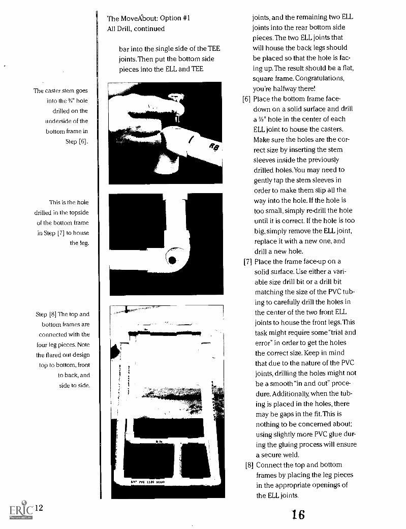
The caster stem goes
into the Yli" hole
drilled on the
underside of the
bottom frame in
Step [6].
This is the hole
drilled in the topside
of the bottom frame
in Step [7] to house
the leg.
Step [8] The top and
bottom frames are
connected with the
four leg pieces. Note
the flared out design
top to bottom, front
to back, and
side to side.
12
The MoveXbout: Option #1
All Drill, continued
bar into the single side of the TEEjoints. Then put the bottom sidepieces into the ELL and TEE
flf
joints, and the remaining two ELL
joints into the rear bottom sidepieces. The two ELL joints that
will house the back legs shouldbe placed so that the hole is fac-ing up. The result should be a flat,
square frame. Congratulations,
you're halfway there![6] Place the bottom frame face-
down on a solid surface and drilla 3/8" hole in the center of each
ELL joint to house the casters.
Make sure the holes are the cor-rect size by inserting the stemsleeves inside the previouslydrilled holes.You may need togently tap the stem sleeves inorder to make them slip all theway into the hole. If the hole istoo small, simply re-drill the holeuntil it is correct. If the hole is too
big, simply remove the ELL joint,
replace it with a new one, anddrill a new hole.Place the frame face-up on asolid surface. Use either a vari-
able size drill bit or a drill bitmatching the size of the PVC tub-ing to carefully drill the holes in
the center of the two front ELLjoints to house the front legs. This
task might require some"trial anderror" in order to get the holesthe correct size. Keep in mindthat due to the nature of the PVCjoints, drilling the holes might notbe a smooth"in and out" proce-dure. Additionally, when the tub-
ing is placed in the holes, theremay be gaps in the fit. This is
nothing to be concerned about;using slightly more PVC glue dur-
ing the gluing process will ensure
a secure weld.[8] Connect the top and bottom
frames by placing the leg piecesin the appropriate openings ofthe ELL joints.
[71
16

[9] Adjust the device until it is sym-
metrical from left to right, top tobottom, side to side and you willhave a precise rectangular shape.After all the adjustments havebeen made, use a marking pen todraw match-up lines on the fit-tings and their respective piecesso that when you start to glue thepieces together the device willnot be disproportionate.
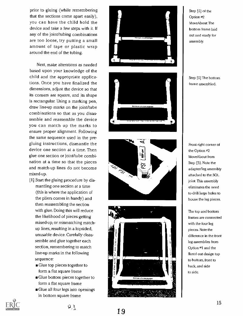
Gluing InstructionsOnce you have put the devicetogether and you are sure the size isaccurate, proceed with the gluinginstructions. If you are not sure aboutthe dimensions, or if you want toobserve the child using the deviceprior to gluing (while rememberingthat the sections come apart easily),you can have the child hold thedevice and take a few steps with it. Ifany of the joint/tubing combinationsare too loose, try putting a smallamount of tape or plastic wraparound the end of the tubing.
Next, make alterations as neededbased upon your knowledge of thechild and the appropriate applica-tions. Once you have finalized thedimensions, adjust the device so thatit is squarely rectangular. Using amarking pen, draw line-up marks onthe joint/tube combinations so thatas you disassemble and reassemblethe device you can match up themarks to ensure proper alignment.
Following the same sequenceused in the pre-gluing instructions,dismantle the device one section at atime. Then glue one section orjoint/tube combination at a time sothat the pieces and match-up linesdo not become mixed-up.
[1] Start the gluing procedure by dis-mantling one section at a time(this is where the application ofthe pliers comes in handy) andthen reassembling the sectionwith glue. Doing this will reducethe likelihood of pieces gettingmixed-up, or mismatching match-up lines, resulting in a lopsided,unusable device. Carefully disas-semble and glue together eachsection, remembering to matchline-up marks in the followingsequence:
Glue top pieces together toform a flat square frameGlue bottom pieces together toform a flat square frameGlue all four legs into openingsin bottom square frameGlue top square frame onto topof legs.
The PVC glue dries very fast (3 to5 seconds), so work quickly witheach assembly and make sure thelines match-up. If you make a mis-take, simply measure and cut newpieces, put the device together fol-lowing the "pre-gluing assemblyinstructions" and resume construc-tion at the point where the erroroccurred.
[2] Place the device upside downand insert the stem of each casterinto the sleeves.You may need topush these with a slight forceuntil a click is heard or felt. If the
17
A side view of the
Move About showing
the match-up lines.
13
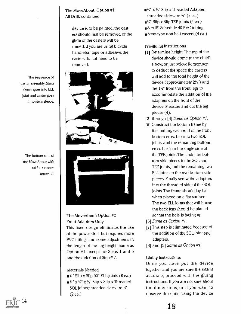
The sequence of
caster assembly: Stem
sleeve goes into ELL
joint and caster goes
into stem sleeve.
The bottom side of
the Move About with
all four casters
attached.
14
The Move About: Option #1
All Drill, continued
device is to be painted, the cast-ers should first be removed or theglide of the casters will beruined. If you are using bicyclehandlebar tape or adhesive, thecasters do not need to beremoved.
n F7 I n 51 r OP^.1
The MoveAbout: Option #2Front Adapters OnlyThis fixed design eliminates the useof the power drill, but requires morePVC fittings and some adjustments inthe length of the leg height. Same asOption #1, except for Steps 1 and 5and the deletion of Step # 7.
Materials Needed3/4" Slip x Slip 90° ELL joints (6 ea.)
w %" x 3/4" x 1/2" Slip x Slip x Threaded
SOL joints; threaded sides are 1/2"
(2 ea.)
3/4" x 1/2" Slip x Threaded Adapter;
threaded sides are 1/2" (2 ea.)
%" Slip x Slip TEE joints (4 ea.)
8 to15' Schedule 40 PVC tubingStem-type non-ball casters (4 ea.)
Pre-gluing InstructionsDetermine height:The top of thedevice should come to the child'selbow, or just below. Remember
to deduct the space the casterswill add to the total height of thedevice (approximately 21/2") and
the 11/4" from the front legs to
accommodate the addition of theadapters on the front of thedevice. Measure and cut the legpieces (4).through [4] Same as Option #1.Construct the bottom frame byfirst putting each end of the frontbottom cross bar into two SOLjoints, and the remaining bottomcross bar into the single side ofthe TEE joints.Then add the bot-tom side pieces to the SOL andTEE joints, and the remaining twoELL joints to the rear bottom sidepieces. Finally, screw the adaptersinto the threaded side of the SOLjoints. The frame should lay flatwhen placed on a flat surface.The two ELL joints that will house
the back legs should be placedso that the hole is facing up.
[6] Same as Option #1.
[7] This step is eliminated because ofthe addition of the SOL joint and
adapters.[8] and [9] Same as Option #1.
[1]
[2]
[5]
Gluing InstructionsOnce you have put the devicetogether and you are sure the size isaccurate, proceed with the gluinginstructions. If you are not sure aboutthe dimensions, or if you want toobserve the child using the device
IS
prior to gluing (while rememberingthat the sections come apart easily),you can have the child hold thedevice and take a few steps with it. Ifany of the joint/tubing combinationsare too loose, try putting a smallamount of tape or plastic wraparound the end of the tubing.
Next, make alterations as neededbased upon your knowledge of thechild and the appropriate applica-tions. Once you have finalized thedimensions, adjust the device so thatits corners are square, and its shapeis rectangular. Using a marking pen,draw line-up marks on the joint/tubecombinations so that as you disas-semble and reassemble the deviceyou can match up the marks toensure proper alignment. Followingthe same sequence used in the pre-gluing instructions, dismantle thedevice one section at a time. Thenglue one section or joint/tube combi-nation at a time so that the piecesand match-up lines do not becomemixed-up.
[1] Start the gluing procedure by dis-mantling one section at a time(this is where the application ofthe pliers comes in handy) andthen reassembling the sectionwith glue. Doing this will reducethe likelihood of pieces gettingmixed-up, or mismatching match-up lines, resulting in a lopsided,unusable device. Carefully disas-semble and glue together eachsection, remembering to matchline-up marks in the following
sequence:Glue top pieces together toform a flat square frameGlue bottom pieces together toform a flat square frameGlue all four legs into openingsin bottom square frame
9 ),
vtril {W.f.
(So,' V> I
f-)
Mfgti
19
Step [5] of the
Option #2
MoveAbout:The
bottom frame laid
out and ready for
assembly.
Step [5] The bottom
frame assembled.
Front right corner of
the Option #2
MoveAbout from
Step [5]. Note the
adapter/leg assembly
attached to the SOL
joint. This assembly
eliminates the need
to drill large holes to
house the leg pieces.
The top and bottom
frames are connected
with the four leg
pieces. Note the
difference in the front
leg assemblies from
Option #1 and the
flared out design top
to bottom, front to
back, and side
to side.
15
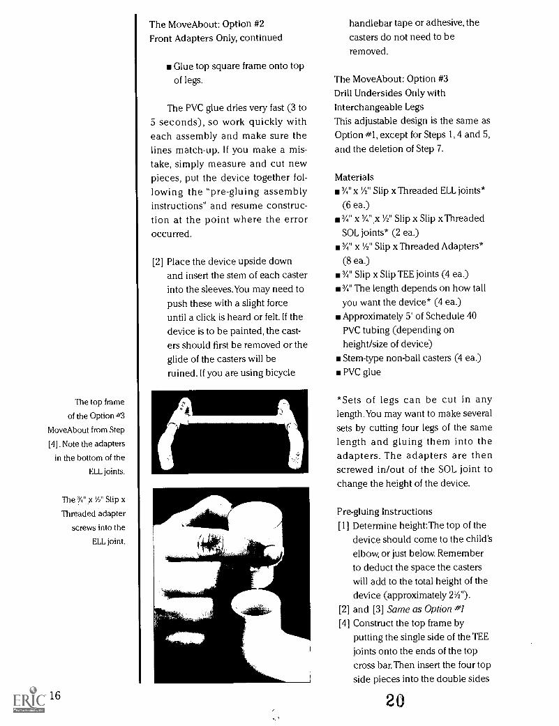
The top frame
of the Option #3
Move About from Step
[4]. Note the adapters
in the bottom of the
ELL joints.
The 3/4" x Y2" Slip x
Threaded adapter
screws into the
ELL joint.
16
The Move About: Option #2Front Adapters Only, continued
Glue top square frame onto topof legs.
The PVC glue dries very fast (3 to5 seconds), so work quickly witheach assembly and make sure thelines match-up. If you make a mis-take, simply measure and cut newpieces, put the device together fol-lowing the "pre-gluing assemblyinstructions" and resume construc-tion at the point where the erroroccurred.
[2] Place the device upside downand insert the stem of each casterinto the sleeves.You may need topush these with a slight forceuntil a click is heard or felt. If the
device is to be painted, the cast-ers should first be removed or theglide of the casters will beruined. If you are using bicycle
handlebar tape or adhesive, thecasters do not need to beremoved.
The Move About: Option #3
Drill Undersides Only with
Interchangeable LegsThis adjustable design is the same asOption #1, except for Steps 1, 4 and 5,
and the deletion of Step 7.
Materials1/4" x 'A" Slip x Threaded ELL joints*
(6 ea.)3/4" x 3/4".x 1/2" Slip x Slip x Threaded
SOL joints* (2 ea.)
1/4" x 1/2" Slip x Threaded Adapters*
(8 ea.)3/4" Slip x Slip TEE joints (4 ea.)
3/4" The length depends on how tall
you want the device* (4 ea.)Approximately 5' of Schedule 40
PVC tubing (depending onheight/size of device)Stem-type non-ball casters (4 ea.)PVC glue
*Sets of legs can be cut in anylength.You may want to make severalsets by cutting four legs of the samelength and gluing them into theadapters. The adapters are thenscrewed in/out of the SOL joint tochange the height of the device.
Pre-gluing Instructions[1] Determine height: The top of the
device should come to the child'selbow, or just below. Remember
to deduct the space the casterswill add to the total height of thedevice (approximately 2Y2").
[2] and [3] Same as Option #1
[4] Construct the top frame byputting the single side of the TEE
joints onto the ends of the topcross bar. Then insert the four topside pieces into the double sides
20

of the TEE joint, and add the four
ELL joints (threaded sides all fac-ing down) on the ends of the topside pieces. Make sure the tubingis completely inside of the fittingby grasping either the joint or thetubing and firmly tapping it onthe ground. Apply this procedureto all joints.
[5] Construct the bottom frame byputting the slip sides of the twoSOL joints onto the ends of thefront bottom cross bar (threadedside up). Then insert the remain-ing bottom cross bar into the sin-gle side of the TEE joints, and addthe bottom side pieces to con-nect the SOL and TEE joints.
Finally, add the remaining two
ELL joints to the rear bottom sidepieces (threaded side up).Theframe should be flat when placedon a flat surface.
[6] Same as Option #1.[7] This step is eliminated because of
the addition of the SOL and ELLjoints and adapters.
[8] and [9] Same as Option #1.
Gluing Instructions
Once you have put the devicetogether and you are sure the size isaccurate, proceed with the gluinginstructions. If you are not sure aboutthe dimensions, or if you want toobserve the child using the deviceprior to gluing (while rememberingthat the sections come apart easily),you can have the child hold thedevice and take a few steps with it. Ifany of the joint/tubing combinationsare too loose, try putting a smallamount of tape or plastic wraparound the end of the tubing.
Next, make alterations as neededbased upon your knowledge of thechild and the appropriate applica-
ceurmemesa.o.
95fanR B3.4. PVC 1198 UM() APO PSI r-
tions. Once you have finalized thedimensions, adjust the device so thatit is squarely rectangular. Using amarking pen, draw line-up marks onthe joint/tube combinations so thatas you disassemble and reassemblethe device you can match up themarks to ensure proper alignment.Following the same sequence usedin the pre-gluing instructions, dis-mantle the device one section at atime. Then glue one section orjoint/tube combination at a time sothat the pieces and match-up linesdo not become mixed-up.[1] Start the gluing procedure by dis-
mantling one section at a time(this is where the application ofthe pliers comes in handy) andthen reassembling the sectionwith glue. Doing this will reducethe likelihood of pieces gettingmixed-up, or mismatching match-
21
Step [5] The bottom
frame of the Option
#3 MoveAbout. Note
the adapters in the
SOL and ELL joints.
The top and bottom
frames are connected
with the four leg
pieces. Note the
adapters in the leg
assemblies and the
flared out design top
to bottom, front to
back, and side to
side.
17
The Move About: Option #3
Drill Undersides Only &Interchangeable Legs, continued
up lines, resulting in a lopsided,unusable device. Carefully disas-semble and glue together eachsection, remembering to matchline-up marks in the following
sequence:Glue top pieces together toform a flat square frameGlue bottom pieces together toform a flat square frameGlue all four legs into adapteropenings in bottom squareframeScrew leg assemblies (leg pieceand adapter) into top and bot-tom frames to complete theOption #3 Move About (see
photo on page 17).
The PVC glue dries very fast (3 to5 seconds), so work quickly witheach assembly and make sure thelines match-up. If you make a mis-take, simply measure and cut newpieces, put the device together fol-lowing the "pre-gluing assemblyinstructions" and resume construc-tion at the point where the erroroccurred.
[2] Place the device upside downand insert the stem of each casterinto the sleeves.You may need topush these with a slight forceuntil a click is heard or felt. If thedevice is to be painted, the cast-ers should first be removed or theglide of the casters will beruined. If you are using bicyclehandlebar tape or adhesive, thecasters do not need to beremoved.
18
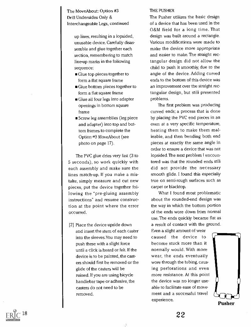
THE PUSHER
The Pusher utilizes the basic designof a device that has been used in theO&M field for a long time. Thatdesign was built around a rectangle.Various modifications were made tomake the device more appropriateand easier to make. The straight rec-tangular design did not allow thechild to push it smoothly, due to theangle of the device. Adding curvedends to the bottom of this device wasan improvement over the straight rec-tangular design, but still presentedproblems.
The first problem was producingcurved ends; a process that is doneby placing the PVC end pieces in anoven at a very specific temperature,heating them to make them mal-leable, and then bending both endpieces at exactly the same angle inorder to ensure a device that was notlopsided. The next problem I encoun-tered was that the rounded ends stilldid not provide the necessarysmooth glide. I found this especiallytrue on semi-rough surfaces such ascarpet or blacktop.
What I found most problematicabout the rounded-end design wasthe way in which the bottom portionof the ends wore down from normaluse. The ends quickly became flat asa result of contact with the ground.Even a slight amount of wearcaused the device tobecome stuck more than itnormally would. With morewear, the ends eventuallywore through the tubing, caus-ing perforations and evenmore resistance. At this pointthe device was no longer use-able to facilitate ease of move-ment and a successful travelexperience.
22
Pusher
The device presented here is theresult of experimenting with variousrevisions of the basic rectangularshape. Following the gluing instruc-tions there are instructions for mak-ing a hand placement modificationfor children who have difficultygrasping the side bars.
Tools and Materials Needed
PVC pipe cutters
Marking penTape measureSafety goggles
PVC glue
IA" thick Schedule 40 or 125 PVC
tubing (amount depends on child'smeasurements, see below)Slip x Slip ELL joints (4 ea.)
45° Slip x Slip ELL joints (2 ea.)
11/4" Slip x Slip connector joints; will
serve as "rollers" (3 ea.)Optional: Spray paint, bicycle han-
dlebar wrap, colored plastic adhe-sive tape, etc., and padding forcenter cross bar
Purchasing extra tubing andjoints will afford a margin of errorand let you experiment with differentlengths and widths.
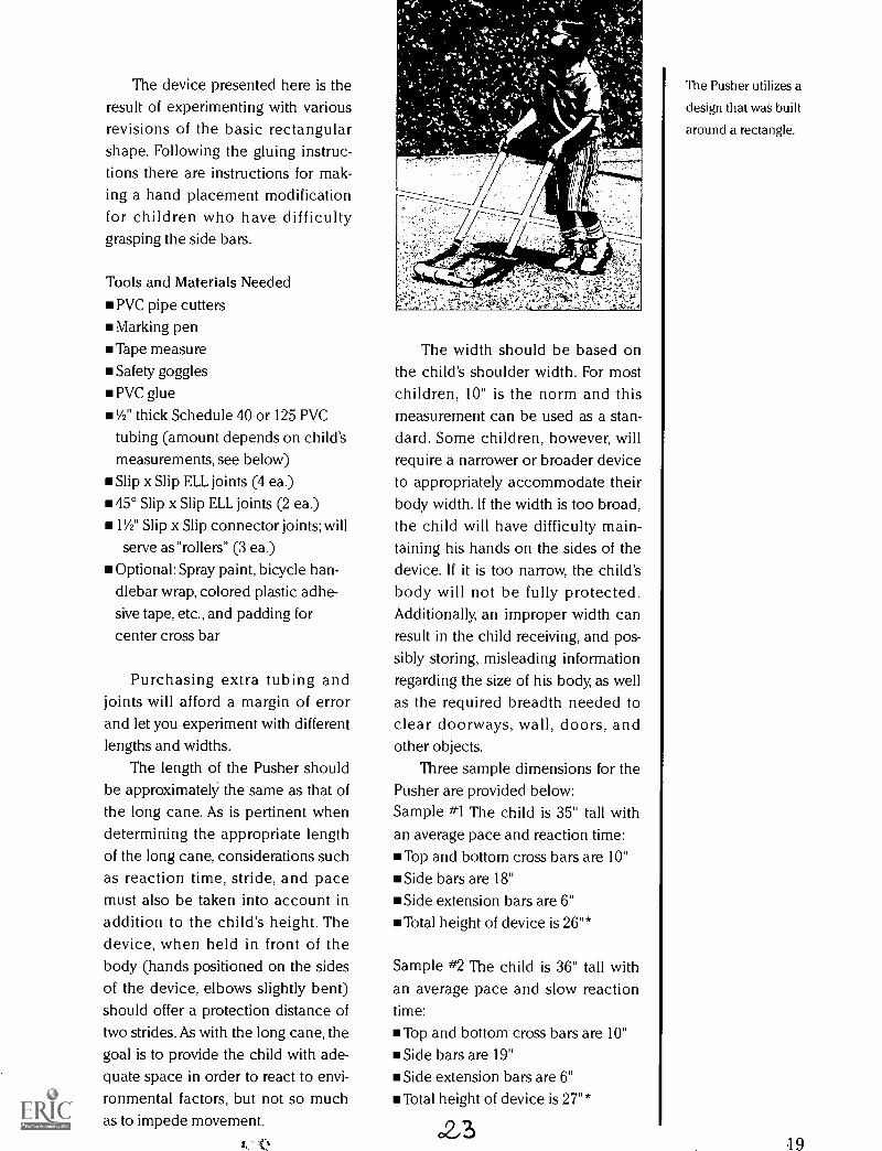
The length of the Pusher shouldbe approximately the same as that ofthe long cane. As is pertinent whendetermining the appropriate lengthof the long cane, considerations suchas reaction time, stride, and pacemust also be taken into account inaddition to the child's height. Thedevice, when held in front of thebody (hands positioned on the sidesof the device, elbows slightly bent)should offer a protection distance oftwo strides. As with the long cane, thegoal is to provide the child with ade-quate space in order to react to envi-ronmental factors, but not so muchas to impede movement.
ss. Q
The width should be based onthe child's shoulder width. For mostchildren, 10" is the norm and thismeasurement can be used as a stan-dard. Some children, however, willrequire a narrower or broader deviceto appropriately accommodate theirbody width. If the width is too broad,the child will have difficulty main-taining his hands on the sides of thedevice. If it is too narrow, the child'sbody will not be fully protected.Additionally, an improper width canresult in the child receiving, and pos-sibly storing, misleading informationregarding the size of his body, as wellas the required breadth needed toclear doorways, wall, doors, andother objects.
Three sample dimensions for thePusher are provided below:Sample #1 The child is 35" tall withan average pace and reaction time:
Top and bottom cross bars are 10"Side bars are 18"Side extension bars are 6"Total height of device is 26"*
Sample #2 The child is 36" tall withan average pace and slow reactiontime:
Top and bottom cross bars are 10"Side bars are 19"Side extension bars are 6"Total height of device is 27"*
23
The Pusher utilizes a
design that was built
around a rectangle.
19
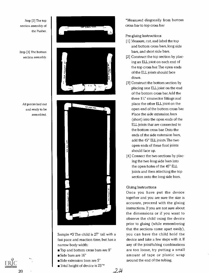
Step [2] The top
section assembly of
the Pusher.
Step [3] The bottom
section assembly.
All pieces laid out
and ready to be
assembled.
20
fimsamm2c.13.
se1410104
Sample #3 The child is 27" tall with afast pace and reaction time, but has anarrow body width:
Top and bottom cross bars are 8"Side bars are 16"Side extension bars are 5"Total height of device is 23"*
4
*Measured diagonally from bottomcross bar to top cross bar
Pre-gluing Instructions[1] Measure, cut, and label the top
and bottom cross bars, long sidebars, and short side bars.
[2] Construct the top section by plac-ing an ELL joint on each end ofthe top cross bar. The open endsof the ELL joints should face
down.Construct the bottom section byplacing one ELL joint on the endof the bottom cross bar. Add thethree 11/2" connector fittings and
place the other ELL joint on theopen end of the bottom cross bar.Place the side extension bars(short) into the open ends of theELL joints that are connected tothe bottom cross bar. Onto theends of the side extension bars,add the 45° ELL joints.The two
open ends of these final jointsshould face up.
[4] Connect the two sections by plac-ing the two long side bars intothe open holes of the 45° ELLjoints and then attaching the topsection onto the long side bars.
[3]
Gluing InstructionsOnce you have put the devicetogether and you are sure the size isaccurate, proceed with the gluinginstructions. If you are not sure aboutthe dimensions or if you want toobserve the child using the deviceprior to gluing (while rememberingthat the sections come apart easily),you can have the child hold thedevice and take a few steps with it. Ifany of the joint/tubing combinationsare too loose, try putting a smallamount of tape or plastic wraparound the end of the tubing.
Next, make alterations as neededbased upon your knowledge of thechild and the appropriate applica-tions. Once you have finalized thedimensions, adjust the device so thatit is squarely rectangular. Using amarking pen, draw line-up marks onthe joint/tube combinations so thatas you disassemble and reassemblethe device you can match up themarks to ensure proper alignment.Following the same sequenCe usedin the pre-gluing instructions, dis-mantle the device one section at atime. Then glue one section orjoint/tube combination at a time sothat the pieces and match-up linesdo not become mixed-up.
Hand Placement ModificationIn addition to the materials neededfor the basic Pusher, you will need:
1/2" Slip x Slip TEE joints (2 ea.)
1/2" Slip end caps (2 ea.)
PVC tubing cut in the followinglengths:
2" lengths (2 ea.)4" lengths (2 ea.)
Follow the above instructions forconstructing the Pusher, with the fol-lowing changes:[1] At [2], add to the open end of the
ELL joints the following assembly:
Place an end cap on one end ofthe 4" pieces of tubing, thenplace the other end of the tubinginto the single open end of oneof the TEE joints. On one end ofthe "T" sides of the same TEE
joint, insert the 2" tubing piece.The other end of the 2" piecegoes into the open end of the ELLjoint from the previously con-structed top section of thePusher. Repeat this procedure toassemble the remaining side.
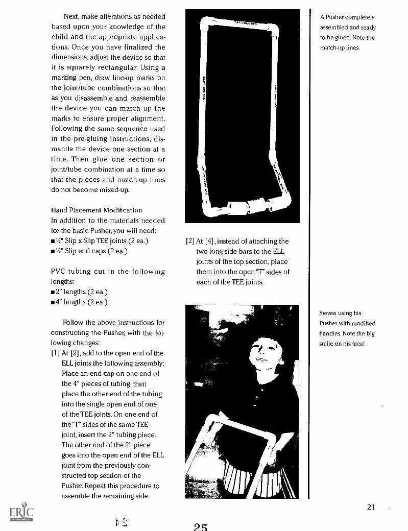
[2] At [4], instead of attaching thetwo long side bars to the ELLjoints of the top section, placethem into the open "T" sides ofeach of the TEE joints.
25
A Pusher completely
assembled and ready
to be glued. Note the
match-up lines.
Steven using his
Pusher with modified
handles. Note the big
smile on his face!
21
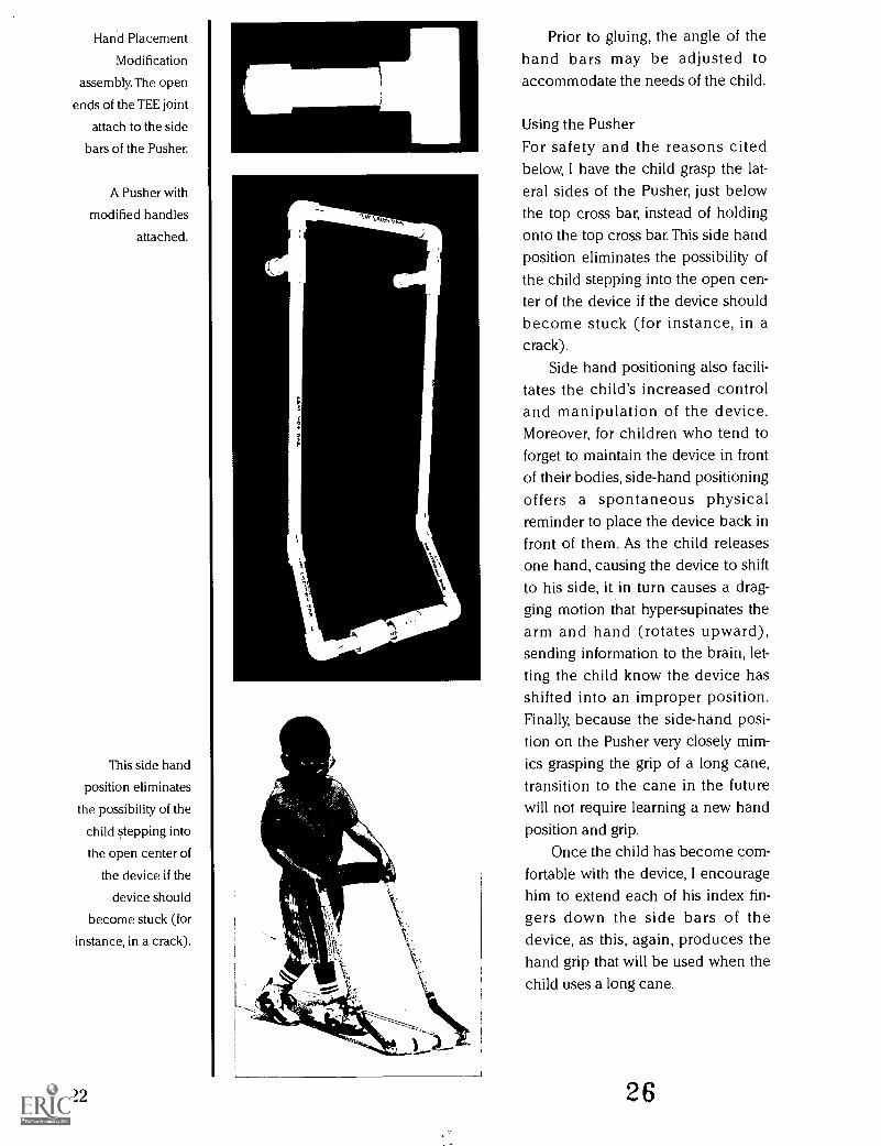
Hand Placement
Modification
assembly. The open
ends of the TEE joint
attach to the side
bars of the Pusher.
A Pusher with
modified handles
attached.
This side hand
position eliminates
the possibility of the
child stepping into
the open center of
the device if the
device should
become stuck (for
instance, in a crack).
El
Prior to gluing, the angle of thehand bars may be adjusted toaccommodate the needs of the child.
Using the PusherFor safety and the reasons citedbelow, I have the child grasp the lat-eral sides of the Pusher, just belowthe top cross bar, instead of holdingonto the top cross bar. This side handposition eliminates the possibility ofthe child stepping into the open cen-ter of the device if the device shouldbecome stuck (for instance, in acrack).
Side hand positioning also facili-tates the child's increased controland manipulation of the device.Moreover, for children who tend toforget to maintain the device in frontof their bodies, side-hand positioningoffers a spontaneous physicalreminder to place the device back infront of them. As the child releasesone hand, causing the device to shiftto his side, it in turn causes a drag-ging motion that hyper-supinates thearm and hand (rotates upward),sending information to the brain, let-ting the child know the device hasshifted into an improper position.Finally, because the side-hand posi-tion on the Pusher very closely mim-ics grasping the grip of a long cane,transition to the cane in the futurewill not require learning a new handposition and grip.
Once the child has become com-fortable with the device, I encouragehim to extend each of his index fin-gers down the side bars of thedevice, as this, again, produces thehand grip that will be used when thechild uses a long cane.
22 26
THE L-BAR
Originally represented by Gene Healyin the TAPS curriculum, the L-Bar has
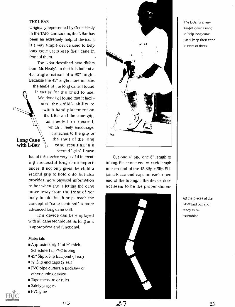
been an extremely helpful device. Itis a very simple device used to helplong cane users keep their cane infront of them.
The L-Bar described here differsfrom Mr. Healy's in that it is built at a45° angle instead of a 90° angle.Because the 45° angle more imitates
the angle of the long cane, I foundit easier for the child to use.Additionally, I found that it facili-
tated the child's ability toswitch hand placement on
the L-Bar and the cane grip,as needed or desired,which I freely encourage.
It attaches to the grip orthe shaft of the longcane, resulting in asecond "grip." I have
found this device very useful in creat-ing successful long cane experi-ences. It not only gives the child asecond grip to hold onto, but alsoprovides more physical informationto her when she is letting the canemove away from the front of herbody. In addition, it helps teach theconcept of "cane centered," a moreadvanced long cane skill.
This device can be employedwith all cane techniques, as long as itis appropriate and functional.
Long Canewith L-Bar
Materials
Approximately 1' of 'A" thick
Schedule 125 PVC tubing45° Slip x Slip ELL joint (1 ea.)
'A" Slip end caps (2 ea.)
PVC pipe cutters, a hacksaw orother cutting deviceTape measure or rulerSafety goggles
PVC glue
Cut one 4" and one 8" length oftubing. Place one end of each lengthin each end of the 45 Slip x Slip ELLjoint. Place end caps on each openend of the tubing. If the device doesnot seem to be the proper dimen-
.27
The L-Bar is a very
simple device used
to help long cane
users keep their cane
in front of them.
All the pieces of the
L-Bar laid out and
ready to be
assembled.
23
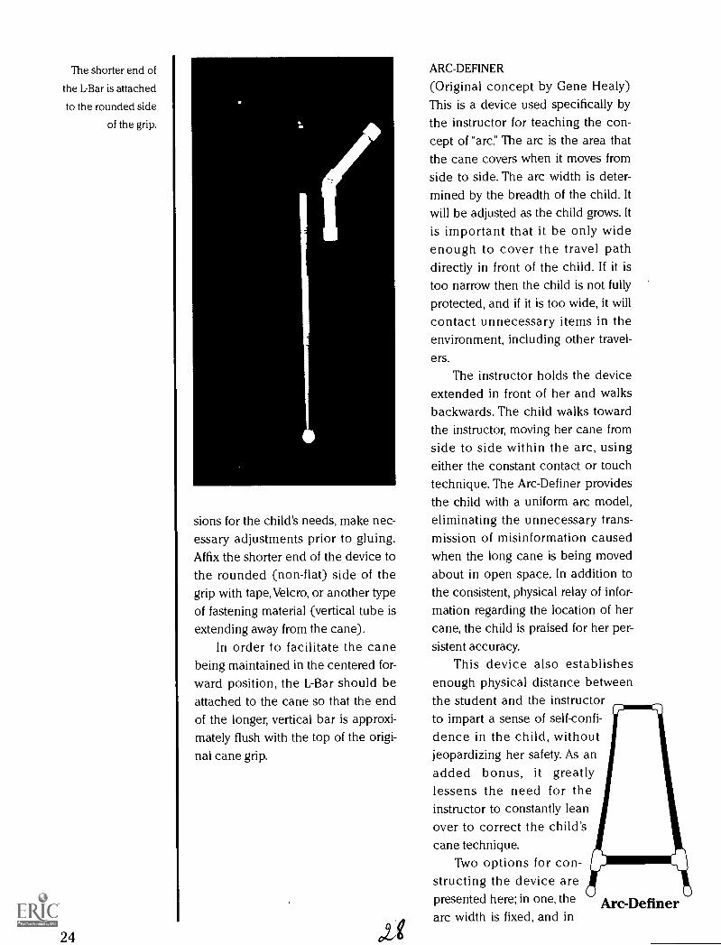
The shorter end of
the L-Bar is attached
to the rounded side
of the grip.
24
sions for the child's needs, make nec-essary adjustments prior to gluing.Affix the shorter end of the device tothe rounded (non-flat) side of thegrip with tape, Velcro, or another typeof fastening material (vertical tube isextending away from the cane).
In order to facilitate the canebeing maintained in the centered for-ward position, the L-Bar should beattached to the cane so that the endof the longer, vertical bar is approxi-mately flush with the top of the origi-nal cane grip.
ote
ARC-DEFINER
(Original concept by Gene Healy)This is a device used specifically bythe instructor for teaching the con-cept of "are The arc is the area thatthe cane covers when it moves fromside to side. The arc width is deter-mined by the breadth of the child. Itwill be adjusted as the child grows. Itis important that it be only wideenough to cover the travel pathdirectly in front of the child. If it istoo narrow then the child is not fullyprotected, and if it is too wide, it willcontact unnecessary items in theenvironment, including other travel-ers.
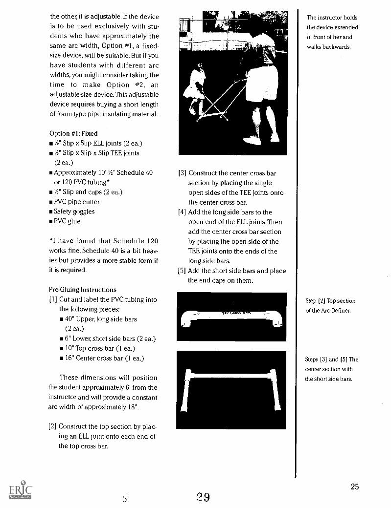
The instructor holds the deviceextended in front of her and walksbackwards. The child walks towardthe instructor, moving her cane fromside to side within the arc, usingeither the constant contact or touchtechnique. The Arc-Definer providesthe child with a uniform arc model,eliminating the unnecessary trans-mission of misinformation causedwhen the long cane is being movedabout in open space. In addition tothe consistent, physical relay of infor-mation regarding the location of hercane, the child is praised for her per-sistent accuracy.
This device also establishesenough physical distance betweenthe student and the instructorto impart a sense of self-confi-dence in the child, withoutjeopardizing her safety. As anadded bonus, it greatlylessens the need for theinstructor to constantly leanover to correct the child'scane technique.
Two options for con-structing the device arepresented here; in one, thearc width is fixed, and in
Arc-Definer
the other, it is adjustable. If the deviceis to be used exclusively with stu-dents who have approximately thesame arc width, Option #1, a fixed-size device, will be suitable. But if you
have students with different arcwidths, you might consider taking thetime to make Option #2, anadjustable-size device. This adjustable
device requires buying a short lengthof foam-type pipe insulating material.
Option #1: Fixed1/2" Slip x Slip ELL joints (2 ea.)
1/2" Slip x Slip x Slip TEE joints
(2 ea.)
Approximately 10' 1/2" Schedule 40
or 120 PVC tubing*
1/2" Slip end caps (2 ea.)
PVC pipe cutter
Safety goggles
PVC glue
*I have found that Schedule 120works fine; Schedule 40 is a bit heav-ier, but provides a more stable form ifit is required.
Pre-Gluing Instructions[1] Cut and label the PVC tubing into
the following pieces:40" Upper, long side bars(2 ea.)
6" Lower, short side bars (2 ea.)10" Top cross bar (1 ea.)
16" Center cross bar (1 ea.)
These dimensions will positionthe student approximately 6' from theinstructor and will provide a constantarc width of approximately 18".
[2] Construct the top section by plac-ing an ELL joint onto each end ofthe top cross bar.
[3] Construct the center cross barsection by placing the singleopen sides of the TEE joints ontothe center cross bar.
[4] Add the long side bars to theopen end of the ELL joints. Then
add the center cross bar sectionby placing the open side of theTEE joints onto the ends of thelong side bars.
[5] Add the short side bars and placethe end caps on them.
29
The instructor holds
the device extended
in front of her and
walks backwards.
Step [2] Top section
of the Arc-Definer.
Steps [3] and [5] The
center section with
the short side bars.
25
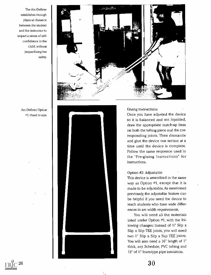
The Arc-Definer
establishes enough
physical distance
between the student
and the instructor to
impart a sense of self-
confidence in the
child, without
jeopardizing her
safety.
Arc-Definer, Option
#1: Fixed in size.
26
j
Gluing InstructionsOnce you have adjusted the deviceso it is balanced and not lopsided,draw the appropriate match-up lineson both the tubing piece and the cor-responding joints. Then dismantleand glue the device one section at atime until the device is complete.Follow the same sequence used inthe "Pre-gluing Instructions" forinstructions.
Option #2: AdjustableThis device is assembled in the sameway as Option #1, except that it ismade to be adjustable. As mentionedpreviously, the adjustable feature canbe helpful if you need the device toteach students who have wide differ-ences in arc width requirements.
You will need all the materialslisted under Option #1, with the fol-lowing changes: Instead of 1/2" Slip xSlip x Slip TEE joints, you will needtwo 1" Slip x Slip x Slip TEE joints.You will also need a 16" length of 1"thick, any Schedule, PVC tubing and12" of Y2" foam-type pipe insulation.
30
Pre-gluing Instructions[1] Cut and label the 1/2" PVC tubing
into the following pieces:48" Side bars (2 ea.)10" Top cross bar (1 ea.)
16" Center cross bar; 1" thick
PVC tubing (1 ea.)
These dimensions will position thestudent approximately 6' from theinstructor and will provide anadjustable arc width of approxi-mately 18" to 30".
[2] Construct the top section by plac-ing an ELL joint onto each end ofthe top cross bar.
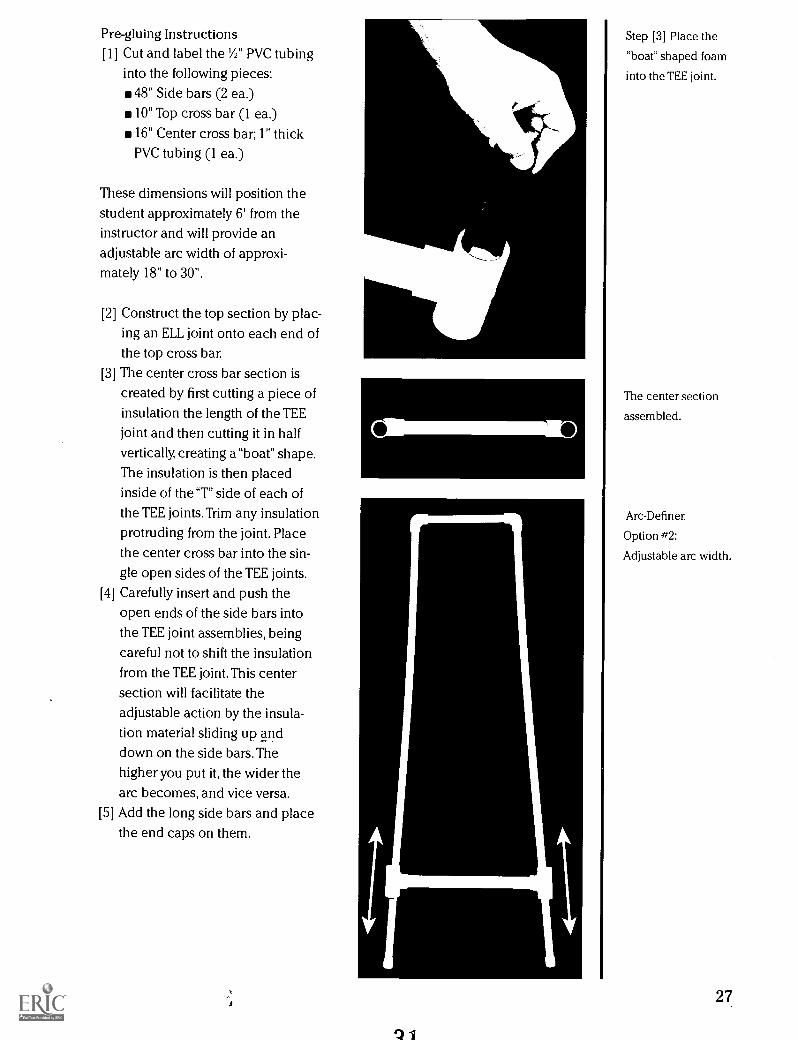
[3] The center cross bar section iscreated by first cutting a piece ofinsulation the length of the TEEjoint and then cutting it in halfvertically, creating a"boat" shape.The insulation is then placedinside of the "T" side of each of
the TEE joints.Trim any insulationprotruding from the joint. Placethe center cross bar into the sin-gle open sides of the TEE joints.
[4] Carefully insert and push theopen ends of the side bars intothe TEE joint assemblies, being
careful not to shift the insulationfrom the TEE joint. This center
section will facilitate theadjustable action by the insula-tion material sliding up anddown on the side bars. Thehigher you put it, the wider thearc becomes, and vice versa.
[5] Add the long side bars and placethe end caps on them.
Step [3] Place the
"boat" shaped foam
into the TEE joint.
The center section
assembled.
Arc-Definer,
Option #2:
Adjustable arc width.
27
28
CONCLUSION
It is my belief that we must have thesame expectations for all children,regardless of any identified orunidentified disability. If we expectmediocre performance that's justwhat we will get.
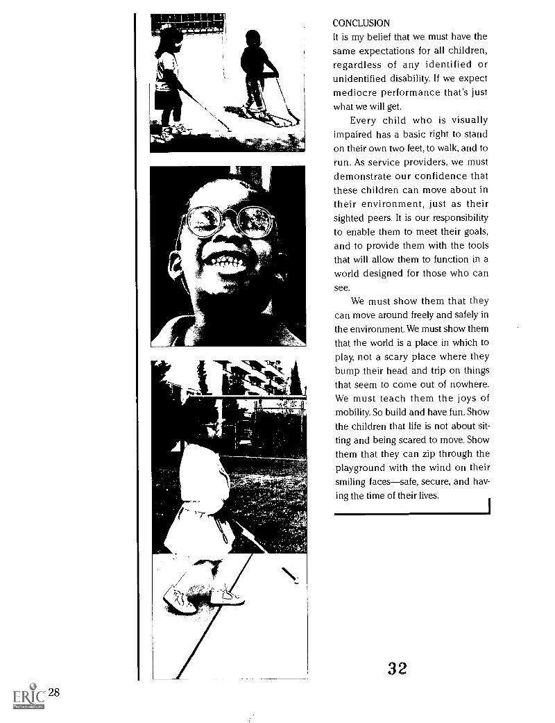
Every child who is visuallyimpaired has a basic right to standon their own two feet, to walk, and torun. As service providers, we mustdemonstrate our confidence thatthese children can move about intheir environment, just as theirsighted peers. It is our responsibilityto enable them to meet their goals,and to provide them with the toolsthat will allow them to function in aworld designed for those who cansee.
We must show them that theycan move around freely and safely inthe environment. We must show them
that the world is a place in which toplay, not a scary place where theybump their head and trip on thingsthat seem to come out of nowhere.We must teach them the joys ofmobility. So build and have fun. Show
the children that life is not about sit-ting and being scared to move. Showthem that they can zip through theplayground with the wind on theirsmiling facessafe, secure, and hav-ing the time of their lives.
32
eighing-just over CASEone pound at STUDIESbirth, Tiffany was
still very small Tiffanywhen she began
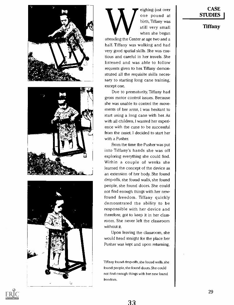
attending the Center at age two and ahalf. Tiffany was walking and hadvery good spatial skills. She was cau-tious and careful in her travels. Shelistened and was able to followrequests given to her. Tiffany demon-strated all the requisite skills neces-sary to starting long cane training,except one.
Due to prematurity, Tiffany hadgross motor control issues. Becauseshe was unable to control the move-ments of her arms, I was hesitant tostart using a long cane with her. Aswith all children, I wanted her experi-ence with the cane to be successfulfrom the onset. I decided to start herwith a Pusher.
From the time the Pusher was putinto Tiffany's hands she was offexploring everything she could find.Within a couple of weeks shelearned the concept of the device asan extension of her body. She founddrop-offs, she found walls, she foundpeople, she found doors. She couldnot find enough things with her new-found freedom. Tiffany quicklydemonstrated the ability to beresponsible with her device andtherefore, got to keep it in her class-room. She never left the classroomwithout it.
Upon leaving the classroom, shewould head straight for the place herPusher was kept and upon returning,
Tiffany found drop-offs, she found walls, she
found people, she found doors. She could
not find enough things with her new found
freedom.
29
carefully replace it. Her O&M lessonsfocused on trailing, protective tech-niques, spatial skills, community out-ings with her Pusher, anddevelopment of long cane skills.
On Tiffany's first off-campus out-ing with the Pusher, she exploredalmost every square inch of theroute! She had been using the devicefor a little over a month. The Center'sstudents were walking to a park thatwas a half-mile away. She traveled the
entire route completely indepen-dentlyexcept for street crossings ofcourse. She found driveways, curbs,parkways, parked cars, fences, andpoles. Everything that could befound, Tiffany found it that day. Thewhole way there she was perfectlycontent and when she found thingsshe had never been able to find onher own, a great big smile wouldspread across her face.
Tiffany's long cane skills weredeveloping right along with her othermobility skills. On her 22" cane weadded an L-Bar on the grip and afour-ounce weight near the tip. TheL-Bar allowed her to use both handson the cane, which helped her keepthe tip on the ground and assistedher in keeping the cane in front ofher body. The added weight furtherhelped her keep the tip on theground. We took the weight on andoff several times during a lesson. Thiswas to constantly remind her mus-cles of the difference in weight, sothat they could exert the correctamount of energy in order to controlthe cane. If we had left the weight onall the time her muscles would accli-mate to that particular weight, and ifwe took it off her muscles wouldbecome confused.
During this time, Tiffany was also
receiving occupational therapy thatwas addressing her gross motor con-
30
trol issues. The added weight wasonly necessary for a couple of weeks.Tiffany quickly learned how to effec-tively keep the tip of her cane on theground. She was very proud of her-self. Although she enjoyed using herPusher, she relished every opportu-nity to use her cane.
Tiffany is currently transitioningto the full-time use of a long caneand will soon no longer employ herPusher.
34
r-
'2111.1.
Air
1
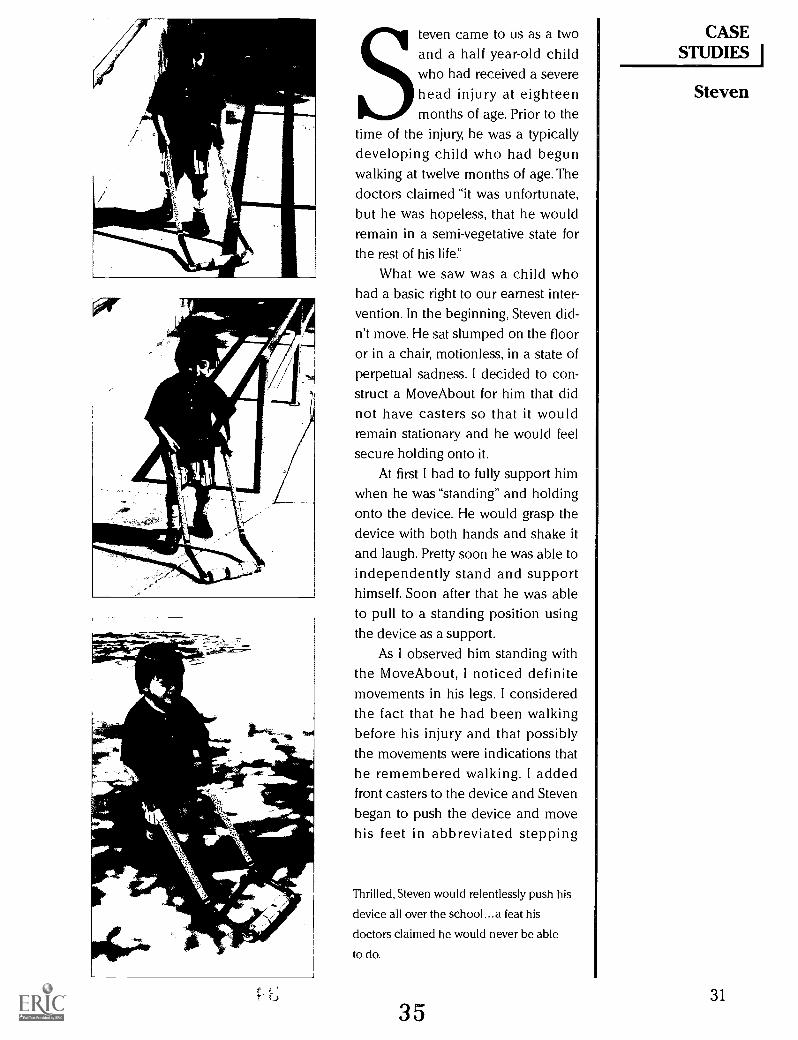
Steven came to us as a twoand a half year-old childwho had received a severehead injury at eighteenmonths of age. Prior to the
time of the injury, he was a typicallydeveloping child who had begunwalking at twelve months of age. Thedoctors claimed "it was unfortunate,but he was hopeless, that he wouldremain in a semi-vegetative state forthe rest of his life
What we saw was a child whohad a basic right to our earnest inter-vention. In the beginning, Steven did-n't move. He sat slumped on the flooror in a chair, motionless, in a state ofperpetual sadness. I decided to con-struct a Move About for him that didnot have casters so that it wouldremain stationary and he would feelsecure holding onto it.
At first I had to fully support himwhen he was "standing" and holdingonto the device. He would grasp thedevice with both hands and shake itand laugh. Pretty soon he was able toindependently stand and supporthimself. Soon after that he was ableto pull to a standing position usingthe device as a support.
As I observed him standing withthe MoveAbout, I noticed definitemovements in his legs. I consideredthe fact that he had been walkingbefore his injury and that possiblythe movements were indications thathe remembered walking. I addedfront casters to the device and Stevenbegan to push the device and movehis feet in abbreviated stepping
Thrilled, Steven would relentlessly push his
device all over the school...a feat his
doctors claimed he would never be able
to do.
motions. This gave him (and me!)great joy. Soon, I added rear casters,which Steven really liked. Because hewas still not yet at the point where hecould control the device on his own,I stood in front of him steadying thedevice at all times. Thrilled, Stevenwould relentlessly push the device allover the school. Soon he began to beable to steady the device himself,navigate with the device, and travelroutes independently.
Soon after this he began to walkindependently of the device; a feathis doctors claimed he would neverbe able to do. Not requiring the secu-rity and stability of a Move About, webegan to transition Steven to aPusher.
Due to partial paralysis of his leftside Steven had difficulty graspingthe side of the device. It was at thistime that the idea of attaching han-dles to the side bars came into play.The addition of the handles allowedhim to hold the device in front ofhim and navigate the environmentsafely and efficiently. An addedbonus of the handles was the supina-tion (turning the arm/hand up) ofthe affected forearm and hand. Thiswas necessary in order to encourageSteven to use his left hand and tokeep his muscles stretched.
During Steven's last year at theCenter, it was decided that we wouldtransition him back to using anunmodified Pusher, as we felt it wasimportant that he have as little adap-tive equipment as necessary. Thetransition was slow and difficult, butonce we started, Steven did not wantto go back to the adaptive handles.The handles had enabled him to usehis arm and hand and he was moreadept at using the Pusher than whenhe first started using it. Initially, anine-ounce weight had to be added
32
to the left side that offered him aphysical reminder to use his hand.But as time passed, we began takingthe weight on and off. There were tworeasons for this. One, we wanted himto be able to use the Pusher withoutthe weight, and two, we wanted himto feel the difference between theweighted and unweighted device.
Currently, Steven is using thedevice without any added weight orother adaptive equipment. He travelsroutes in the school independently,runs freely outdoors, and is able totravel safely and efficiently.
36
0
Tj
rJ
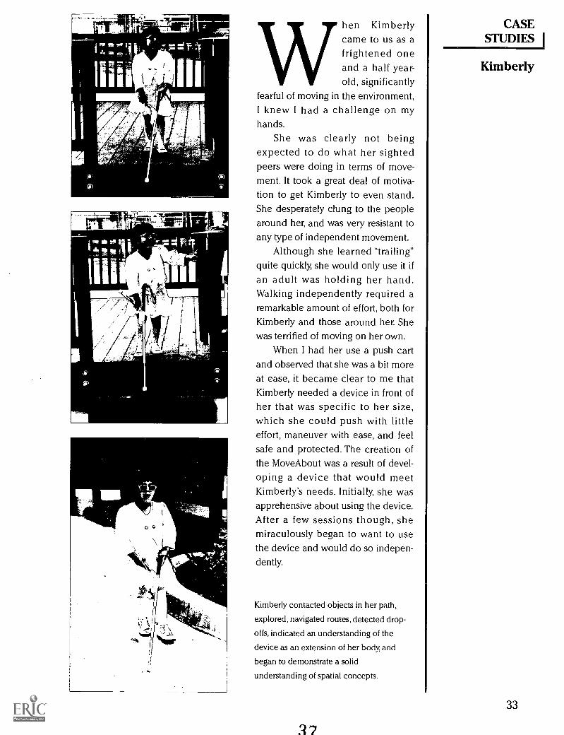
hen Kimberly CASEcame to us as a STUDIESfrightened oneand a half year- Kimberlyold, significantly
fearful of moving in the environment,I knew I had a challenge on myhands.
She was clearly not beingexpected to do what her sightedpeers were doing in terms of move-ment. It took a great deal of motiva-tion to get Kimberly to even stand.She desperately clung to the peoplearound her, and was very resistant toany type of independent movement.
Although she learned "trailing"quite quickly, she would only use it ifan adult was holding her hand.Walking independently required aremarkable amount of effort, both forKimberly and those around her. Shewas terrified of moving on her own.
When I had her use a push cartand observed that she was a bit moreat ease, it became clear to me thatKimberly needed a device in front ofher that was specific to her size,which she could push with littleeffort, maneuver with ease, and feelsafe and protected. The creation ofthe MoveAbout was a result of devel-oping a device that would meetKimberly's needs. Initially, she wasapprehensive about using the device.After a few sessions though, shemiraculously began to want to usethe device and would do so indepen-dently.
Kimberly contacted objects in her path,
explored, navigated routes, detected drop-
offs, indicated an understanding of the
device as an extension of her body, and
began to demonstrate a solid
understanding of spatial concepts.
33
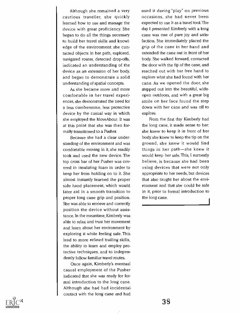
Although she remained a verycautious traveller, she quicklylearned how to use and manage thedevice with great proficiency. Shebegan to do all the things necessaryto build her travel skills and knowl-edge of the environment: she con-tacted objects in her path, explored,navigated routes, detected drop-offs,indicated an understanding of thedevice as an extension of her body,and began to demonstrate a solidunderstanding of spatial concepts.
As she became more and morecomfortable in her travel experi-ences, she demonstrated the need fora less cumbersome, less protectivedevice by the casual way in whichshe employed the Move About. It wasat this point that she was then for-mally transitioned to a Pusher.
Because she had a clear under-standing of the environment and wascomfortable moving in it, she readilytook and used the new device. Thetop cross bar of her Pusher was cov-ered in insulating foam in order tokeep her from holding on to it. Shealmost instantly learned the properside hand placement, which wouldlater aid in a smooth transition toproper long cane grip and position.She was able to retrieve and correctlyposition the device without assis-tance. In the meantime, Kimberly wasable to relax and trust her movementand learn about her environment byexploring it while feeling safe. Thislead to more refined trailing skills,the ability to learn and employ pro-tective techniques, and to indepen-dently follow familiar travel routes.
Once again, Kimberly's eventualcasual employment of the Pusherindicated that she was ready for for-mal introduction to the long cane.Although she had had incidental,contact with the long cane and had
34
used it during "play" on previousoccasions, she had never beenexpected to use it as a travel tool. Theday I presented Kimberly with a longcane was one of pure joy and satis-faction. She immediately placed thegrip of the cane in her hand andextended the cane out in front of herbody. She walked forward, contactedthe door with the tip of the cane, andreached out with her free hand toexplore what she had found with hercane. As we opened the door, shestepped out into the beautiful, wide-open outdoors, and with a great bigsmile on her face found the stepdown with her cane and was off toexplore.
From the first day Kimberly hadthe long cane, it made sense to her:she knew to keep it in front of herbody, she knew to keep the tip on theground, she knew it would findthings in her pathshe knew itwould keep her safe. This, I earnestlybelieve, is because she had beenusing devices that were not onlyappropriate to her needs, but devicesthat also taught her about the envi-ronment and that she could be safein it, prior to formal introduction tothe long cane.
38

Anthony, T. L. (1993). Orientation and
mobility skill development. InFirst Steps:A handbook for teach-
ing young children who are visu-ally impaired, (pp. 115-138). Los
Angeles: Blind Childrens Center.
Bosbach, S.R. (1988). Precane mobil-
ity devices. Journal of Visual
Impairment & Blindness, 82, 338-339.
Clarke, K. (1988). Barriers or
enablers? Mobility devices for
visually impaired multihandi-
capped infants and preschoolers.Education of the VisuallyHandicapped, 20, 115-132.
Clarke, K.L., Sainato, D.M., & Ward,
M.E. (1994). Travel Performance
of Preschoolers: The Effects of
Mobility Training With a Long
Cane Versus a Precane. Journal ofVisual Impairment & Blindness,1, 19-30.
Cratty, B. (1971). Movement and spa-
tial awareness in blind childrenand youth. Springfield, IL: Charles
C Thomas.
Cratty, B.J., & Sams, T.A. (1968). The
body-imagery of blind children.
New York:American Foundationfor the Blind.
Dentith, A. (1994). Orientation and
mobility: The only way to go!
CTEVH Journal, XXXVIII, (3), 28-
29.
Ehresman, P (1995). Free-standing
canes. RE:view, 1, 15-23.
Fazzi, D.L. (1992). Movement focus:
Mobility devices. In R.L. Pogrund,
D.L. Fazzi & J.S. Lampert (Eds.),
Early Focus: Working with young
blind and visually impaired child-
ren and their families, (pp. 104-111). New York:American
Foundation for the Blind.Fazzi, D.L. & J.S. Lampert (Eds.), Early
Focus: Working with young blind
and visually impaired children
and their families, (pp. 104-111). BIBLIOGRAPHY INew York: American Foundation
for the Blind.
Ferrell, K.A. (1979). Orientation and
mobility for preschool children:
What we have and what weneed. Journal of Visual
Impairment & Blindness, 73, 147-
150.
Foy, C., Kirchner, D., & Waple, L.
(1991). The Connecticut precane:
Case study in curriculum. Journal
of Visual Impairment &Blindness, 85, 85-85.
Foy, C.,Von Schneden, M., &
Waiculonis, J. (1992). The
Connecticut precane: Case study
in curriculum. Journal of Visual
Impairment & Blindness, 86, 178-
181.
Hill, E.W, Dodson-Burk, B, & Smith,
B.A. (1989). Orientation and
mobility for infants who are visu-
ally impaired. RE:view, 21, 47-60.
Hill, E.W., Rosen, S., Correa,V.I., &
Langley, M.B. (1984). Preschool
orientation and mobility: An
expanded definition. Education ofthe Visually Handicapped, 16 (2),
58-72.
Joffee, E., & Rikhye, C. (1991). A home-
based orientation and mobilityprogram for infants and toddlers.
Journal of Visual Impairment &Blindness, 82, 282-285.
Pogrund, R.L., & Rosen, S.J. (1989).
The preschool blind child can bea cane user. Journal of Visual
Impairment & Blindness, 83, 431-
438.
Welsh, R.L. & Blasch, B.B. (1980).
Foundations of orientation andmobility. New York: American
Foundation for the Blind, 358.
Witte, L. (1993). Precane devices in a
residential school setting. Journalof Visual Impairment &Blindness, 87, 205-206.
1q
35

ACKNOWLEDGEMENTS
Standing on my own two feet: A step-by-step guide to designing and con-structing simple, individually tailoredadaptive mobility devices forpreschool-age children who are visu-ally impaired was developed as aresult of the response and interestgenerated by professional presenta-tions given by our Orientation &Mobility instructor, Lorie LynnLaPrelle, M.A. The principles involved
are universal; however, the personal-ized design and the ease of construc-tion of the devices are the result ofLorie Lynn's keen observation andcreativity.
Special thanks goes to Diane L.Fazzi, Ph.D. for her careful review ofthe material. Her training andencouragement were instrumental inthe development of the devices andof this book. Our sincere thank youto Megan Minnehan Smith for donat-ing her time as our photographer andfor her donation of the color film andprocessing. Also, we would like tothank Charles Peloso Photography,Inc. for their generous donation ofthe black and white film and process-ing.
We especially acknowledge thecourage and perseverance of thechildren who undauntingly workedthrough the stages of mobility toreach their goal of independence.The sheer joy on their faces was allthe inspiration we needed to bringthis information to you.
Midge Horton
Executive DirectorBlind Childrens Center
36
BLIND CHILDRENS CENTER
The Blind Childrens Center offers aprogram of diversified services whichmeets the special needs of childrenwho are blind, visually impaired, andmulti-handicapped blind (ages birththrough five years), their parents, andsiblings at no charge. Servicesinclude: Infant Stimulation Program;Educational Preschool; FamilySupport Services; Information &Referral Program; Toll Free NationalPhone Line; Research Program; andInternship Opportunities. Publi-cations are produced regularly forparents and professionals.
A non-profit organization, theBlind Childrens Center is available tochildren who are blind and partiallysighted regardless of race, color,national or ethnic origin, sex, or reli-gion. Founded in 1938, the Center is a
project of the Southern CaliforniaDelta Gammas. The Blind ChildrensCenter operates without state or fed-eral assistance.
40

At>
Blind Childrens Center4120 Marathon Street
Los Angeles
California
9002941

(9/92)
U.S. DEPARTMENT OF EDUCATIONOffice of Educational Research and Improvement (OERI)
Educational Resources information Center (ERIC)
NOTICE
REPRODUCTION BASIS
ERIC
This document is covered by a signed "Reproduction Release(Blanket)" form (on file within the ERIC system), encompassing allor classes of documents from its source organization and, therefore,does not require a "Specific Document" Release form.
This document is Federally-funded, or carries its own permission toreproduce, or is otherwise in the public domain and, therefore, maybe reproduced by ERIC without a signed Reproduction Releaseform (either "Specific Document" or "Blanket").