Embed Size (px)
Citation preview

Documentation | EN
FBB-B903Fieldbus Box for PROFINET
21.08.2014 | Version: 1.1.1

Table of contents
FBB-B903 3Version: 1.1.1
Table of contents1 Foreword .................................................................................................................................................... 5
1.1 Notes on the documentation.............................................................................................................. 51.2 Safety instructions ............................................................................................................................. 61.3 Documentation issue status .............................................................................................................. 71.4 Bus Coupler as a general term.......................................................................................................... 8
2 Product overview....................................................................................................................................... 92.1 The Fieldbus Box System.................................................................................................................. 92.2 Fieldbus Box - Naming conventions ................................................................................................ 112.3 Firmware and hardware issue status............................................................................................... 132.4 Technical data ................................................................................................................................. 14
3 Mounting and wiring................................................................................................................................ 153.1 Dimensions...................................................................................................................................... 153.2 Ethernet Connection........................................................................................................................ 163.3 Ethernet connector: M12 ................................................................................................................. 17
4 Ethernet .................................................................................................................................................... 184.1 Overview.......................................................................................................................................... 18
4.1.1 Ethernet ........................................................................................................................... 184.1.2 Topology .......................................................................................................................... 204.1.3 Ethernet Cable................................................................................................................. 21
5 Parameterization and commissioning................................................................................................... 235.1 Note about parameterization ........................................................................................................... 235.2 Start-up behavior of the Fieldbus Box ............................................................................................. 245.3 Network Classes.............................................................................................................................. 255.4 IP address, PROFINET name ......................................................................................................... 26
5.4.1 Address switch settings ................................................................................................... 265.4.2 Address setting with coding switches and KS2000 ......................................................... 275.4.3 Setting the IP Address Using the Beckhoff BootP Server ............................................... 285.4.4 Address Configuration via DHCP Server......................................................................... 295.4.5 Subnet mask.................................................................................................................... 295.4.6 Testing the IP Address .................................................................................................... 305.4.7 Reading the MAC-ID........................................................................................................ 30
6 Configuration ........................................................................................................................................... 316.1 GSDML configuration file................................................................................................................. 316.2 Mapping of the Coupler Box ............................................................................................................ 326.3 DAP (Device Access Point) of the Coupler Box .............................................................................. 336.4 Configuration with S7 ...................................................................................................................... 34
6.4.1 Example with Step 7 ........................................................................................................ 34
7 Error handling and diagnosis................................................................................................................. 377.1 Diagnostic LEDs - Overview............................................................................................................ 377.2 Diagnostic LEDs for PROFINET...................................................................................................... 387.3 Diagnostic LEDs for local errors ...................................................................................................... 417.4 Check of the IP-Link connection...................................................................................................... 43

Table of contents
FBB-B9034 Version: 1.1.1
8 Accessories ............................................................................................................................................. 468.1 Fieldbus Box accessories................................................................................................................ 468.2 Power cables ................................................................................................................................... 47
9 Appendix .................................................................................................................................................. 489.1 General operating conditions........................................................................................................... 489.2 Approvals......................................................................................................................................... 509.3 Test standards for device testing..................................................................................................... 519.4 Support and Service ........................................................................................................................ 52

Foreword
FBB-B903 5Version: 1.1.1
1 Foreword
1.1 Notes on the documentation
Intended audience
This description is only intended for the use of trained specialists in control and automation engineering whoare familiar with the applicable national standards.It is essential that the documentation and the following notes and explanations are followed when installingand commissioning these components.It is the duty of the technical personnel to use the documentation published at the respective time of eachinstallation and commissioning.
The responsible staff must ensure that the application or use of the products described satisfy all therequirements for safety, including all the relevant laws, regulations, guidelines and standards.
Disclaimer
The documentation has been prepared with care. The products described are, however, constantly underdevelopment.
We reserve the right to revise and change the documentation at any time and without prior announcement.
No claims for the modification of products that have already been supplied may be made on the basis of thedata, diagrams and descriptions in this documentation.
Trademarks
Beckhoff®, TwinCAT®, EtherCAT®, EtherCAT G®, EtherCAT G10®, EtherCAT P®, Safety over EtherCAT®,TwinSAFE®, XFC®, XTS® and XPlanar® are registered trademarks of and licensed by Beckhoff AutomationGmbH. Other designations used in this publication may be trademarks whose use by third parties for theirown purposes could violate the rights of the owners.
Patent Pending
The EtherCAT Technology is covered, including but not limited to the following patent applications andpatents: EP1590927, EP1789857, EP1456722, EP2137893, DE102015105702 with correspondingapplications or registrations in various other countries.
EtherCAT® is registered trademark and patented technology, licensed by Beckhoff Automation GmbH,Germany.
Copyright
© Beckhoff Automation GmbH & Co. KG, Germany.The reproduction, distribution and utilization of this document as well as the communication of its contents toothers without express authorization are prohibited.Offenders will be held liable for the payment of damages. All rights reserved in the event of the grant of apatent, utility model or design.
Foreword
FBB-B9036 Version: 1.1.1
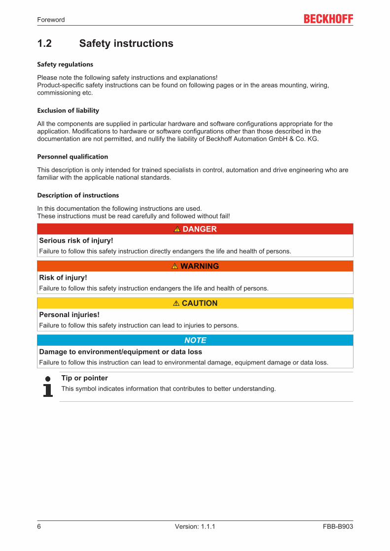
1.2 Safety instructions
Safety regulations
Please note the following safety instructions and explanations!Product-specific safety instructions can be found on following pages or in the areas mounting, wiring,commissioning etc.
Exclusion of liability
All the components are supplied in particular hardware and software configurations appropriate for theapplication. Modifications to hardware or software configurations other than those described in thedocumentation are not permitted, and nullify the liability of Beckhoff Automation GmbH & Co. KG.
Personnel qualification
This description is only intended for trained specialists in control, automation and drive engineering who arefamiliar with the applicable national standards.
Description of instructions
In this documentation the following instructions are used. These instructions must be read carefully and followed without fail!
DANGERSerious risk of injury!Failure to follow this safety instruction directly endangers the life and health of persons.
WARNINGRisk of injury!Failure to follow this safety instruction endangers the life and health of persons.
CAUTIONPersonal injuries!Failure to follow this safety instruction can lead to injuries to persons.
NOTEDamage to environment/equipment or data lossFailure to follow this instruction can lead to environmental damage, equipment damage or data loss.
Tip or pointerThis symbol indicates information that contributes to better understanding.

Foreword
FBB-B903 7Version: 1.1.1
1.3 Documentation issue statusVersion Comment1.1.1 System overview updated1.1 Pictures corrected1.0 First release

Foreword
FBB-B9038 Version: 1.1.1
1.4 Bus Coupler as a general termParts of this manual give general information about Ethernet implementation in Beckhoff products.Thus in the following often the term Bus Coupler is used, that describes not only the IP20 products, but alsomeans the IP67 modules.
Product overview
FBB-B903 9Version: 1.1.1
2 Product overview
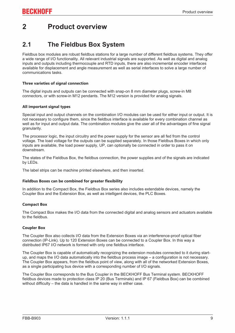
2.1 The Fieldbus Box SystemFieldbus box modules are robust fieldbus stations for a large number of different fieldbus systems. They offera wide range of I/O functionality. All relevant industrial signals are supported. As well as digital and analoginputs and outputs including thermocouple and RTD inputs, there are also incremental encoder interfacesavailable for displacement and angle measurement as well as serial interfaces to solve a large number ofcommunications tasks.
Three varieties of signal connection
The digital inputs and outputs can be connected with snap-on 8 mm diameter plugs, screw-in M8connectors, or with screw-in M12 pendants. The M12 version is provided for analog signals.
All important signal types
Special input and output channels on the combination I/O modules can be used for either input or output. It isnot necessary to configure them, since the fieldbus interface is available for every combination channel aswell as for input and output data. The combination modules give the user all of the advantages of fine signalgranularity.
The processor logic, the input circuitry and the power supply for the sensor are all fed from the controlvoltage. The load voltage for the outputs can be supplied separately. In those Fieldbus Boxes in which onlyinputs are available, the load power supply, UP, can optionally be connected in order to pass it ondownstream.
The states of the Fieldbus Box, the fieldbus connection, the power supplies and of the signals are indicatedby LEDs.
The label strips can be machine printed elsewhere, and then inserted.
Fieldbus Boxes can be combined for greater flexibility
In addition to the Compact Box, the Fieldbus Box series also includes extendable devices, namely theCoupler Box and the Extension Box, as well as intelligent devices, the PLC Boxes.
Compact Box
The Compact Box makes the I/O data from the connected digital and analog sensors and actuators availableto the fieldbus.
Coupler Box
The Coupler Box also collects I/O data from the Extension Boxes via an interference-proof optical fiberconnection (IP-Link). Up to 120 Extension Boxes can be connected to a Coupler Box. In this way adistributed IP67 I/O network is formed with only one fieldbus interface.
The Coupler Box is capable of automatically recognizing the extension modules connected to it during start-up, and maps the I/O data automatically into the fieldbus process image – a configuration is not necessary.The Coupler Box appears, from the fieldbus point of view, along with all of the networked Extension Boxes,as a single participating bus device with a corresponding number of I/O signals.
The Coupler Box corresponds to the Bus Coupler in the BECKHOFF Bus Terminal system. BECKHOFFfieldbus devices made to protection class IP 20 (Bus Terminals) and IP 67 (Fieldbus Box) can be combinedwithout difficulty – the data is handled in the same way in either case.

Product overview
FBB-B90310 Version: 1.1.1
IP-Link
The IP-Link is an optical fiber connection with a transmission rate of 2 MBits/s which is capable oftransmitting 1000 items of binary I/O data in approx. 1 ms, rapidly and securely. Smaller configurations arecorrespondingly faster. Because of the high usable data rate, the coupling via IP-Link does not reduce theperformance of the fieldbus at all.
Low-priced plug connectors made according to Protection Class IP 67 can be used for the rapid and simplepreparation of the IP-Link cable, in situ. The connection does not require special tools, and can be performedquickly and simply. The IP-Link cables can also be obtained with prepared plugs if required.
The separate supply of the output voltage allows output groups to be switched off individually. Differingpotentials can also be created within an extension ring without difficulty, since the IP-Link naturally hasoptimum electrical isolation.
Extension box
Like the Compact Boxes, the Extension Boxes cover the full spectrum of I/O signals, and may be up to 15 mapart. They are remarkably small in size, and lead to particularly economical I/O solutions with high levels ofprotection. Here again, the digital inputs and outputs may optionally be connected via snap-on 8 mmconnectors, or via screw-in connectors (M8 and M12). Analog signal types are provided with the M12version. The snap-on connectors lock in place positively, forming a shake-proof connection, while the screw-in connectors offer the advantage of high resistance to being pulled out.
PLC Box
The PLC Box is an intelligent Fieldbus Box with PLC functionality for distributed pre-processing of the I/Osignals. This allows parts of the application to be farmed out from the central controller. This reduces theload on the CPU and the fieldbus. Distributed counting, controlling and switching are typical applications forthe PLC Box. The reaction times are independent of the bus communication and of the higher-levelcontroller.
In the event of a bus or controller failure, maintenance of function (e.g. bringing the process to a safe state inan orderly manner) is possible.
Programming is carried out with TwinCAT in accordance with IEC 61131-3. Five different programminglanguages are available:
• Instruction List (IL)• Function Block Diagram (FBD)• Ladder Diagram (LD)• Sequential Function Chart (SFC)• Structured Text (ST)
The program download occurs either via the fieldbus or via the programming interface.
Extensive debugging functions (breakpoint, single step, monitoring, etc) are also available. The PLC Boxcontains a powerful 16 bit controller, 32/96 kByte program memory and 32/64 kByte data memory. A further512 bytes of non-volatile memory are available for remanent flags.
PLC Box with IP-Link
The programmable PLC Box with IP-Link provides almost unlimited I/O possibilities. Up to 120 extensionmodules, with more than 2000 I/Os, can be directly addressed from the PLC program. The PLC Box is thusalso suitable for use as a small, autonomous controller for the operation of parts of equipment or smallmachines.

Product overview
FBB-B903 11Version: 1.1.1
2.2 Fieldbus Box - Naming conventionsThe identifications of the Fieldbus Box modules are to be understood as follows:IXxxxy-zyyy
IX describes the design:
"IP" stands for the Compact Box design [} 12]"IL" stands for the Coupler Box design (with IP-Link) [} 12]"IE" stands for the Extension Box design [} 12]
xxxy describes the I/O connection:
xxx describes the I/O property:"10x" - 8 x digital inputs"15x" - counter module"20x" - 8 x digital outputs"25x" - PWM module"23x" - 4 x digital inputs and 4 x digital outputs"24x" - 8 x digital inputs and 8 x digital outputs"3xx" - 4 x analog inputs"4xx" - 4 x analog outputs"5xx" - incremental encoder or SSI transducer"6xx" - Gateway module for RS232, RS422, RS485, TTY
y represents the mechanical connection:"0" stands for 8mm snap-on connection,"1" stands for M8 bolted connection"2" stands for M12 bolted connection and"9" stands for M23 bolted connection
zyyy describes the programmability and the fieldbus system
z distinguishes whether the device is a slave or is a programmable slave:
"B" - not programmable"C" - programmable (PLC Box)
"yyy" stands for the fieldbus system and the bus connection:"110" - EtherCAT"200" - Lightbus"310" - PROFIBUS"318" - PROFIBUS with integrated tee-connector"400" - Interbus"510" - CANopen"518" - CANopen with integrated tee-connector"520" - DeviceNet"528" - DeviceNet with integrated tee-connector"730" - Modbus"800" - RS485"810" - RS232"900" - Ethernet TCP/IP with RJ45 for the bus connection"901" - Ethernet TCP/IP with M12 for the bus connection"903" - PROFINET"905" - EtherNet/IP

Product overview
FBB-B90312 Version: 1.1.1
Compact Box
Compact Box
The Compact Box modules offer a wide range of I/O functionality. All relevant industrial signals aresupported. The digital inputs and outputs can be connected either with snap-on 8 mm diameter plugs, screw-in M8 connectors, or screw-in M12 connectors. The M12 version is made available for analog signals.
Depending on the module, the I/O section and the power supply section can differ.
Coupler Box
Coupler Box
There are three versions of the coupler box named IL230x-Bxxx. It differs from the compact box in that thismodule offers an interface to what are known as extension boxes. This interface is a subsidiary bus systembased on the optical fiber what is known as IP Link. This powerful subsidiary bus system can handle up to120 extension boxes at one coupler box.
Extension Box
Extension Box
Extension Modules, that are independent of the fieldbus and that can only be operated together with acoupler box via IP Link.
PLC Box
PLC Box
A PLC Box differ from the Coupler Box in that this module can be programmed in IEC 61131-3. This meansthat this slave is also capable of working autonomously, without a master, for instance for control orregulation tasks.
Also see about this2 Fieldbus Box - Naming conventions [} 12]

Product overview
FBB-B903 13Version: 1.1.1
2.3 Firmware and hardware issue statusThe documentation refers to the hardware and software status that was valid at the time it was prepared.The properties are subject to continuous development and improvement. Modules having earlier productionstatuses cannot have the same properties as modules with the latest status. Existing properties, however,are always retained and are not changed, so that these modules can always be replaced by new ones.The number beginning with a D allows you to recognize the firmware and hardware status of a module.
Syntax:
D . ww yy x y z u
ww - calendar weekyy - yearx - bus board firmware statusy - bus board hardware statusz - I/O board firmware statusu - I/O board hardware status
Example:
D.22081501
- Calendar week 22- in the year 2008- bus board firmware status: 1- bus board firmware hardware status: 5- I/O board firmware status: 0 (no firmware is necessary for this board)- I/O board hardware status: 1

Product overview
FBB-B90314 Version: 1.1.1
2.4 Technical dataTechnical data IL230x-B903Extension modules max. 120Digital peripheral signals max. 960 inputs and outputsAnalog peripheral signals max. 480 inputs and outputsTransmission medium 4 x 2 twisted pair copper cable; category 5 (100
Mbaud)Data transfer rate 100 MbaudTopology star wiringDistance between modules 100 m (hub/switch to Fieldbus Box)Configuration via KS2000 or via the controllerProtocols PROFINET RT (TCP-ADS for access via Ethernet
with KS2000 configuration software)Power supply Control voltage: 24VDC (-15%/+20%); load voltage:
According to I/O typeControl voltage current consumption According to I/O type + current consumption of
sensors, max. 0.5 ALoad voltage current consumption According to I/O typePower supply connection Feed: 1 x M8 plug, 4-pin
Onward connection: 1 x M8 female socket 4-pinFieldbus connection 1 x M12, d-coded socketElectrical isolation Channels/control voltage: no
between the channels: noControl voltage/fieldbus: yes
Permissible ambient temperature range duringoperation
0°C ... +55°C
Permissible ambient temperature range duringstorage
-25°C ... +85°C
Vibration / shock resistance conforms to EN 60068-2-6 / EN 60068-2-27,EN 60068-2-29
EMC immunity/emission Conforms to EN 61000-6-2 / EN 61000-6-4Protection class IP 65/66/67 (conforms to EN 60529)Installation position VariableApprovals CE, UL E172151
NoteDetailed technical data for all available I/O variants can be found under Signal variants, Installation,I/O module configuration on Products & Solutions CD from Beckhoff or on the Internet (http://www.beckhoff.com) under Download/Fieldbus Box.

Mounting and wiring
FBB-B903 15Version: 1.1.1
3 Mounting and wiring
3.1 Dimensions
All dimensions are given in millimeters.
General
Technical data Fieldbus BoxMaterial PA6 (polyamide), casting compound: polyurethaneAssembly 2 x fixing holes for M3Metal parts Brass, nickel-platedContacts CuZn, gold-platedVibration / shock resistance according to EN 60068-2-6 / EN 60068-2-27,
EN 60068-2-29EMC resistance burst / ESD according to EN 61000-6-2 (EN 50082) /
EN 61000-6-4 (EN 50081)Permissible ambient temperature during operation 0 ... 55°CPermissible ambient temperature during storage -25 ... + 85°CInstallation position anyType of protection IP65/66/67 when screwed togetherApprovals CE, UL E172151
IPxxxx-Bxx8, IL230x-Bxx8, IL230x-B110, IXxxxx-B400, IXxxxx-B90x, IXxxxx-C900
Technical data Compact and Coupler Box with integrated teeconnector
Dimensions (H x W x D) ca. 210 x 30 x 26,5 mm (height to upper edge offieldbus socket: 30 mm)
Weight ca. 260 g - 290 g, depending on module type
IPxxxx-Bxx0, IL230x-Bxx0, IL230x-Cxx0
Technical data Compact and Coupler BoxDimensions (H x W x D) Approx. 175 x 30 x 26.5 mm (height to upper edge of
fieldbus socket: 30 mm, with T- connectorZS1031-2600 height approx. 65 mm)
Weight Approx. 250 g - 280 g, depending on module type
IExxxx
Technical data Extension boxDimensions (H x W x D) Approx. 126 x 30 x 26.5 mmWeight Approx. 120 g - 200 g, depending on module type

Mounting and wiring
FBB-B90316 Version: 1.1.1
3.2 Ethernet ConnectionThe connection to the Ethernet bus is made via an d-coded M12 female socket.
The cable should be CAT5 or CAT5e cable.
Cabling
Connection via hub or switch
Connect the PLC's network interface to the hub using a standard Ethernet cable, and connect the hub, againusing a standard Ethernet cable, to the Fieldbus Box.
Connection via a switch is done in the same way.
Direct connection between PLC and IL230x-B90x
To connect the PLC directly to the Fieldbus Box, you must use an Ethernet cable in which the pairs of coreshave been crossed (a crossover cable).
Pin assignment of the M12 connector
PIN Signal Description1 TD + Transmit Data +2 RD + Receive Data +3 TD - Transmit Data -4 RD - Receive Data -housing Shield Shield
Note: There is no standardized color setting for the wires!

Mounting and wiring
FBB-B903 17Version: 1.1.1
3.3 Ethernet connector: M12The connection to the Ethernet is done with an d-coded M12 socket (IP67).

Ethernet
FBB-B90318 Version: 1.1.1
4 Ethernet
4.1 Overview
4.1.1 EthernetEthernet was originally developed by DEC, Intel and XEROX (as the DIX standard) for passing data betweenoffice devices. The term nowadays generally refers to the IEEE 802.3 CSMA/CD specification, published in1985. Because of the high acceptance around the world this technology is available everywhere and is veryeconomical. This means that it is easy to make connections to existing networks.
There are now a number of quite different transmission media: coaxial cable (10Base5), optical fiber(10BaseF) or twisted pairs (10BaseT) with screen (STP) or without screen (UTP). A variety of topologiessuch as ring, line or star can be constructed with Ethernet.
Ethernet transmits Ethernet packets from a sender to one or more receivers. This transmission takes placewithout acknowledgement, and without the repetition of lost packets. To achieve reliable datacommunication, there are protocols, such as TCP/IP, that can run on top of Ethernet.
MAC-ID
The sender and receiver of Ethernet packets are addressed by means of the MAC-ID. The MAC-ID is a 6byte identification code unique to every Ethernet device in the world. The MAC-ID consists of two parts. Thefirst part (i.e. the first 3 bytes) is a manufacturer identifier. The identifier for Beckhoff is 00 01 05. The next 3bytes are assigned by the manufacturer and implement a unique serial number. The MAC-ID can, forexample, be used for the BootP protocol in order to set the TCP/IP number. This involves sending atelegram containing the information such as the name or the TCP/IP number to the corresponding node. Youcan read the MAC-ID with the KS2000 configuration software.
The Internet Protocol (IP)
The internet protocol (IP) forms the basis of this data communication. IP transports data packets from onedevice to another; the devices can be in the same network, or in different networks. IP here looks after theaddress management (finding and assigning MAC-IDs), segmentation and routing. Like the Ethernetprotocol, IP does not guarantee that the data is transported - data packets can be lost, or their sequence canbe changed.
TCP/IP was developed to provide standardized, reliable data exchange between any number of differentnetworks. TCP/IP is thus substantially independent of the hardware or software being used. Although theterm is often used as if it were a single concept, a number of protocols are layered together: e.g. IP, TCP,UDP, ARP and ICMP.
Transmission Control Protocol (TCP)
The Transmission Control Protocol (TCP) which runs on top of IP is a connection-oriented transport protocol.It includes error detection and error handling mechanisms. Lost telegrams are repeated.
User Datagram Protocol (UDP)
UDP is connectionless transport protocol. It provides no control mechanism when exchanging data betweensender and receiver. This results in a higher processing speed than, for example, TCP. Checking whether ornot the telegram has arrived must be carried out by the higher-level protocol.
Ethernet
FBB-B903 19Version: 1.1.1
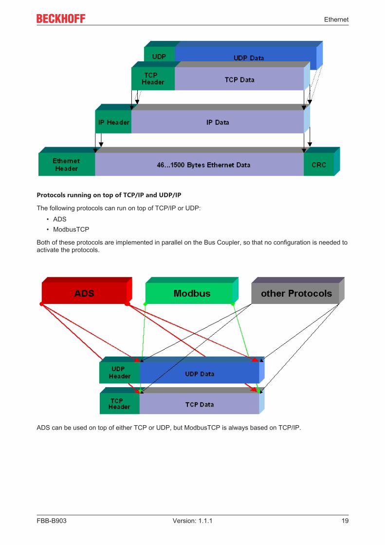
Protocols running on top of TCP/IP and UDP/IP
The following protocols can run on top of TCP/IP or UDP:
• ADS• ModbusTCP
Both of these protocols are implemented in parallel on the Bus Coupler, so that no configuration is needed toactivate the protocols.
ADS can be used on top of either TCP or UDP, but ModbusTCP is always based on TCP/IP.

Ethernet
FBB-B90320 Version: 1.1.1
4.1.2 TopologyIn 10BaseT and 100BaseT a number of stations are star connected according to the Ethernet standard.
Star topology
The simplest form of a star LAN consists of a single point-to-point connection. All messages pass via acentral node (the hub or switch), which then passes the information to the desired device according to thedestination address.
Tree topology
A tree topology consists of a number of connected star networks. As soon as the network contains a numberof hubs or switches, the topology is classified as a tree. Ideally the connections between the star couplershave a particularly wide bandwidth, since these transport the most traffic. When constructing tree topologies,the repeater rule must be observed. This is also known as the 5-4-3 repeater rule. There must be no morethan two pairs of repeaters (or of hubs) in the transmission path between any two stations, unless they areseparated by bridges, switches or routers. A transmission path may consist of at most five segments andfour repeater sets (two repeater pairs). Up to three of these segments may be coaxial segments to which thestations are connected. The remaining segments must consist of point-to-point connections; these are alsoknown as IRL (inter repeater link) connections.
Cabling guidelines
Structured cabling provides general guidelines for constructing the cabling for a LAN. It specifies maximumpermitted cable lengths for the wiring within the grounds, building or floor. Standardized in EN 50173, ISO11801 and TIA 568-A, structured cabling provides the basis for an advanced, application-independent andeconomical network infrastructure. The wiring standards are applicable to a range defined as having ageographical extent of up to 3 km and an office area of up to one million sq meters, with between 50 and50,000 end devices. Recommendations for the structure of a cabling system are also given. The figures canvary, depending on the topology selected, the transmission media and coupling modules used underindustrial conditions, and on the use of components from various manufacturers in one network. The givenfigures should therefore only be considered as recommendations.

Ethernet
FBB-B903 21Version: 1.1.1
4.1.3 Ethernet Cable
Transmission standards
10Base5
The transmission medium for 10Base5 consists of a thick coaxial cable ("yellow cable") with a max.transmission speed of 10 MBaud arranged in a line topology with branches (drops) each of which isconnected to one network device. Because all the devices are in this case connected to a commontransmission medium, it is inevitable that collisions occur often in 10Base5.
10Base2
10Base2 (Cheapernet) is a further development of 10Base5, and has the advantage that the coaxial cable ischeaper and, being more flexible, is easier to lay. It is possible for several devices to be connected to one10Base2 cable. It is frequent for branches from a 10Base5 backbone to be implemented in 10Base2.
10BaseT
Describes a twisted pair cable for 10 MBaud. The network here is constructed as a star. It is no longer thecase that every device is attached to the same medium. This means that a broken cable no longer results infailure of the entire network. The use of switches as star couplers enables collisions to be reduced. Usingfull-duplex connections they can even be entirely avoided.
100BaseT
Twisted pair cable for 100 MBaud. It is necessary to use a higher cable quality and to employ appropriatehubs or switches in order to achieve the higher data rate.
10BaseF
The 10BaseF standard describes several optical fiber versions.
Short description of the 10BaseT and 100BaseT cable types
Twisted pair copper cable for star topologies, where the distance between two devices may not exceed 100meters.
UTP
Unshielded twisted pairThis type of cable belongs to category 3, and is not recommended for use in an industrial environment.
S/UTP
Screened/unshielded twisted pair (screened with copper braid)Has a general screen of copper braid to reduce influence of external interference. This cable isrecommended for use with Bus Couplers.
FTP
Foiled shielded twisted pair (screened with aluminum foil)This cable has an outer screen of laminated aluminum and plastic foil.
S/FTP
Screened/foiled-shielded twisted pair (screened with copper braid and aluminum foil)Has a laminated aluminum screen with a copper braid on top. Such cables can provide up to 70 dB reductionin interference power.

Ethernet
FBB-B90322 Version: 1.1.1
STP
Shielded twisted pairDescribes a cable with an outer screen, without defining the nature of the screen any more closely.
S/STP
Screened/shielded twisted pair (wires are individually screened)This identification refers to a cable with a screen for each of the two wires as well as an outer shield.
ITP
Industrial Twisted-PairThe structure is similar to that of S/STP, but, in contrast to S/STP, it has only one pair of conductors.

Parameterization and commissioning
FBB-B903 23Version: 1.1.1
5 Parameterization and commissioning
5.1 Note about parameterizationNoteChanges, e.g. the MAC-ID, that were done with the KS2000 configuration software are only storedin the volatile memory (RAM) of the Fieldbus Box.After the changes a software reset is required. Bythis, the changes will be copied into the flash memory and are permanent.A Cold-Start (Power-ON/OFF) is not enough. It has to be a software reset!

Parameterization and commissioning
FBB-B90324 Version: 1.1.1
5.2 Start-up behavior of the Fieldbus BoxAfter power up, the Fieldbus Box checks its state, configures the IP-Link (if present) and refers to theextension modules to create a structure list. If the Fieldbus Box contains a decentralized controller (IL230x-C310) the local PLC is started once the structure list has successfully been created.The I/O LEDs illuminate and flash as the module starts up. If there are no errors, the I/O LEDs should stopflashing within about 2-3 seconds. If there is an error, then the LED that flashes will depend on the type ofthat error (see Diagnostic LEDs [} 37]).

Parameterization and commissioning
FBB-B903 25Version: 1.1.1
5.3 Network ClassesThree different network classes are distinguished. They specify how many address bits are reserved for theNetwork -ID and how many for the computer number (or node number). The difference is located in the first 3bits of the IP address.
Network-class
Number of bitsfor the Network ID
Possible numberof networks
Number of bits forthe node address
Possible numberofnodes per net-work
A 7 126 24 16 777 214B 14 16 382 16 65 536C 21 2 097 150 8 254
NOTEWarningAn IP address must be unique within the entire connected network!
NoteIn a communication with another Ethernet devices, the IP address set must have the same networkclass. Example: Your PC has address 172.16.17.55, which means that the Bus Coupler must haveaddress 172.16.xxx.xxx (each xxx stands for a number between 0...255. The 0 is normally used forrouters/switches, and should therefore be reserved).
In order to see the PC's own address, the command ipconfig can be entered into a DOS window underWindows NT/2000/XP.

Parameterization and commissioning
FBB-B90326 Version: 1.1.1
5.4 IP address, PROFINET name
5.4.1 Address switch settingsVia the address switch you can select between different addressing options and assign the PROFINETname.
NoteThe device is PROFINET-compliant if switches x10 and x1 are set to 0xEx or > 0xF1.
All other modes are available as options.
PROFINET name via switch
This is where the name "il230x-b903-xx" is formed. xx corresponds to the switch setting. "il" is must be lowercase!
Hex switchx16
Hex switchx1
Description Restart behaviour Behaviour withfactory settings
0x0 - D 0x0 - F IP address viaswitch
- PN name frommemory- IP address viaswitch
- PN namebecomes emptystring- IP address viaswitch172.16.18.xxx (xxxswitch)SNM 255.255.0.0
0xF 0x0 IP address viaDHCP
- PN name frommemory- IP address andSNM via DHCP
- PN namebecomes emptystring- IP address andSNM via DHCP
0xF 0x1 IP address viaBootP
- PN name frommemory- IP address andSNM via BootP
- PN namebecomes emptystring- IP address =0.0.0.0,- SNM = 0.0.0.0
0xE 0x0 - F PN name viaswitch x1
- PN name viaswitch*(il230x-b903-xx,with xx = 0...15)- IP address frommemory
- PN name viaswitch- IP address =0.0.0.0,- SNM = 0.0.0.0
0xF 0x2 - F PROFINET-compliant
PN name frommemory- IP address frommemory
- PN namebecomes emptystring- IP address =0.0.0.0,- SNM = 0.0.0.0
*) The PROFINET name cannot be overwritten by the controller.
Parameterization and commissioning
FBB-B903 27Version: 1.1.1
Legend
PN - PROFINETSNM - SubNetMaskDHCP - Dynamic Host Configuration ProtocolDNS - Domain Name Server
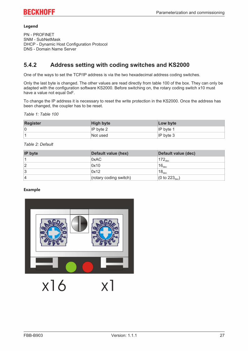
5.4.2 Address setting with coding switches and KS2000One of the ways to set the TCP/IP address is via the two hexadecimal address coding switches.
Only the last byte is changed. The other values are read directly from table 100 of the box. They can only beadapted with the configuration software KS2000. Before switching on, the rotary coding switch x10 musthave a value not equal 0xF.
To change the IP address it is necessary to reset the write protection in the KS2000. Once the address hasbeen changed, the coupler has to be reset.
Table 1: Table 100
Register High byte Low byte0 IP byte 2 IP byte 11 Not used IP byte 3
Table 2: Default
IP byte Default value (hex) Default value (dec)1 0xAC 172dec
2 0x10 16dec
3 0x12 18dec
4 (rotary coding switch) (0 to 223dec)
Example

Parameterization and commissioning
FBB-B90328 Version: 1.1.1
Switch x16 x1Valence 16 1In this example
Switch settings 0 4
Value 0 4dec
IP address 172.16.18.4
5.4.3 Setting the IP Address Using the Beckhoff BootP ServerFor address setting with the Beckhoff BootP server set the rotary coding switch to 0x F1. The TCP/IPERROR LED flashes while the address is being allocated.
IP address save modes
Rotary coding switch in position 0x F1
The IP address assigned by the BootP server is only valid until the module is switched off. The BootP servermust assign a new IP address to the module at the next cold start.The address is, however, retained through a software reset of the module.
Beckhoff BootP server
Beckhoff supply a BootP server for Windows 98, ME, NT4.0, NT2000 and XP. The installation version canbe found on the Beckhoff TwinCAT CD in folder Unsupported Utilities or under http://download.beckhoff.com/download/Software/TwinCAT/TwinCAT2/Unsupported Utilities/TcBootP Server.

Parameterization and commissioning
FBB-B903 29Version: 1.1.1
As soon as the BootP server has started, the New MAC Address window shows all the Beckhoff nodes thatare working in BootP mode and still have not received an IP address. The allocation MAC ID [} 30] for IPaddress takes place via button "<<". Successful assignment is displayed in the log window.To start the BootP server automatically when your PC boots, it is only necessary to provide a shortcut in theWindows autostart folder. Include the /Start parameter in the shortcut (.../TcBootPDlg.exe/start).
5.4.4 Address Configuration via DHCP ServerTo set the address by means of a DHCP server, set the rotary switches to 0xF0. In this state, the DHCPservice is switched on, and the module is automatically assigned an IP number by the DHCP server. For thispurpose the DHCP server must know the module's MAC-ID [} 30]. The IP address should be set statically.The TCP/IP Error LED flashes while the address is being allocated.
5.4.5 Subnet maskThe subnet mask is subject to the control of the network administrator, and specifies the structure of thesubnet.
Small networks without a router do not require a subnet mask. The same is true if you do not use registeredIP numbers. A subnet mask can be used to subdivide the network with the aid of the mask instead of using alarge number of network numbers.
The subnet mask is a 32-bit number.
• Ones in the mask indicate the subnet part of an address region.• Zeros indicate that part of the address region which is available for the host IDs.

Parameterization and commissioning
FBB-B90330 Version: 1.1.1
Description Binary representation Decimal representationIP address 10101100.00010000.00010001.11
001000172.16.17.200
Subnet mask 11111111.11111111.00010100.00000000
255.255.20.0
Network ID 10101100.00010000.00010000.00000000
172.16.16.0
Host ID 00000000.00000000.00000001.11001000
0.0.1.200
Standard subnet mask
Address class Standard subnet mask (decimal) Standard subnet mask (hex)A 255.0.0.0 FF.00.00.00B 255.255.0.0 FF.FF.00.00C 255.255.255.0 FF.FF.FF.00
NoteNeither subnet 0 nor the subnet consisting only of ones may be used. Neither host number 0 northe host number consisting only of ones may be used! If the IP address is set using the KS2000configuration software, it is necessary for the subnet mask also to be changed with the KS2000configuration software. If ARP addressing is used, the associated standard subnet mask, based onthe IP address, is entered. Under BootP or DHCP the subnet mask is entered by the server.
5.4.6 Testing the IP AddressUse the Ping command to test the IP address.
5.4.7 Reading the MAC-IDProceed as follows to read the MAC-ID:
• Change the IP address of your PC to 172.16.x.x and the Subnet mask to 255.255.0.0The default IP address of the Ethernet Fieldbus Boxes is 172.16.18.1 (rotary switch setting: 0, 1).
• Start the DOS Window• Send a Ping to IP address 172.16.17.1• Read the MAC-ID with arp -a.

Configuration
FBB-B903 31Version: 1.1.1
6 Configuration
6.1 GSDML configuration fileDownload the configuration file for the PROFINET master from the Beckhoff website at www.beckhoff.com
If required, a firmware update is available via [email protected].
Figure illustrating the application with Siemens Step7
The corresponding image (*.bmp) can also be found on the Beckhoff website.
Copy the image into the following directory: "\Siemens\Step7\S7DATA\NSBMP".

Configuration
FBB-B90332 Version: 1.1.1
6.2 Mapping of the Coupler BoxThe signals of the Coupler Box and the connected expansion boxes are mapped in the order in which thehardware is connected.
For digital boxes always at least one byte is reserved.If the boxes have less than 8 bits, the rest is filled with zeros.
The data are represented with WORD alignment, i.e. for analog modules the first WORD contains the statusbyte and an empty byte.Example: IE2301 4 digital inputs, 4 digital outputs, 8-bit input, 8-bit output; the first four bits 0-3 are assigned.Bits 4-7 are not used.
Complex boxes are represented with input and output process image.
Example
IE3102, 4-channel analog input: per channel 1 byte control or status information, 1 empty byte, 2 bytes data.

Configuration
FBB-B903 33Version: 1.1.1
6.3 DAP (Device Access Point) of the Coupler BoxThe device model chosen for PROFINET is the distributed periphery, which is familiar from PROFIBUS DP.
The slots of the modular devices are represented via slots and sub slots.
Slot 0 is designated as device access point (DAP). This is where writing to the module takes place.
The current value of the control bit is returned in the status bits. Also, in bits 8 - 15 an IP-Link counter or thecurrent IP-Link cycle time is displayed, depending on "S" in control bit 6.
Status bits
31 - 24 23 - 16 15 - 8 7 6 5 4 3 2 1 0IP-Linkerrorargument
IP-Linkerrorcode
IP-Linkcounteror IP-Linkcycletimer
- S - - L2 - R1 K1
K1: IP-Link reset was triggered
R1: Reboot of IL230x-B903 was triggered
L2: IP-Link stop in the event of Profinet error
Control bits
31 - 24 23 - 16 15 - 8 7 6 5 4 3 2 1 0- - - - S - - L2 - R1 K1
K1: 0 -> 1 trigger IP-Link reset
R1: Reboot of IL230x-B903 was triggered
L2: IP-Link stop in the event of PROFINET error
S: =1 IP-Link cycle time in ms

Configuration
FBB-B90334 Version: 1.1.1
6.4 Configuration with S7
6.4.1 Example with Step 7Install the GSDML file (Step 7 from version 5.4 + SP1)
To this end open the hardware manager. Install the GSDML file.
Add an IL230x-B903 node in your Manager and add the expansion modules according to your configuration.

Configuration
FBB-B903 35Version: 1.1.1
Set the name of the PN device, e.g. "il230x-b903-10" ["il" must be in lower case] (set the address switches ofthe box to 0xFF, then switch on then the coupler).
The configuration will now look as follows, for example. Load the configuration into your control system.

Configuration
FBB-B90336 Version: 1.1.1
Error handling and diagnosis
FBB-B903 37Version: 1.1.1
7 Error handling and diagnosis
7.1 Diagnostic LEDs - Overview
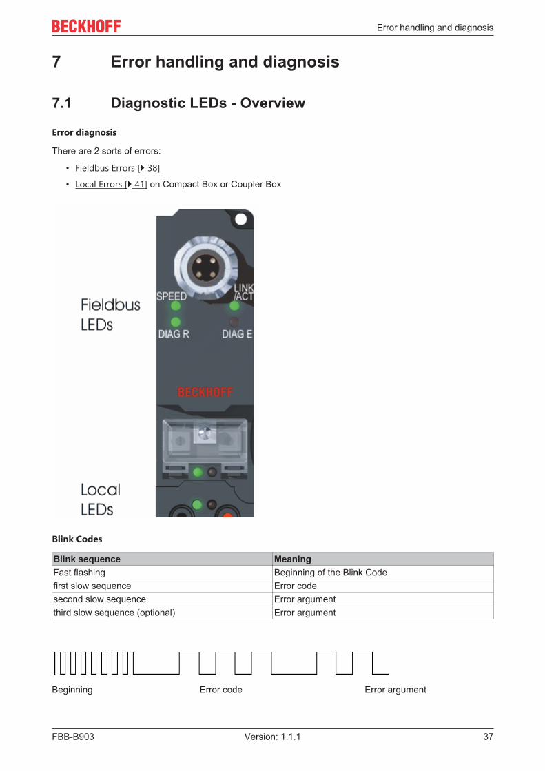
Error diagnosis
There are 2 sorts of errors:
• Fieldbus Errors [} 38]
• Local Errors [} 41] on Compact Box or Coupler Box
Blink Codes
Blink sequence MeaningFast flashing Beginning of the Blink Codefirst slow sequence Error codesecond slow sequence Error argumentthird slow sequence (optional) Error argument
Beginning Error code Error argument

Error handling and diagnosis
FBB-B90338 Version: 1.1.1
7.2 Diagnostic LEDs for PROFINETAfter switching on, the module immediately checks the connected configuration. Error-free start-up issignalled by the red LED I/O ERR being extinguished. Flashing of LED I/O ERR indicates an input/outputerror. The error code can be determined from the frequency and number of blinks. This permits rapidrectification of the error.
The module has two groups of LEDs for the display of status. The upper group with four LEDs indicates thestatus of the respective fieldbus. The meaning of the fieldbus status LEDs is explained in the respectivesections of this manual. It corresponds to the usual fieldbus display.
At the bottom of the module there are two further green LEDs that indicate the supply voltage. The LED onthe left indicates the 24 VDC logic supply of the module. The LED on the right indicates the supply of theoutputs.
Fig. 1: B90x_DiaLED
LEDs for Ethernet diagnostics
LED On OffSPEED Port setting 100Mbit/s Port setting 10Mbit/sACT On: Physical connection present
Flashing: Bus traffic presentNo connection

Error handling and diagnosis
FBB-B903 39Version: 1.1.1
LEDs for PROFINET diagnostics
DIAG R (green) DIAG E (red) Configuration/diagnosticson off OK0.5s off Flashing (triggered by a Profinet
tool)0.1s off Offline PLC Stopoff 0.5s TimeOut1 Slot number Wrong module2 Slot number Missing module (physical)3 Slot number Missing module (in the
configuration)4 off No Profinet name allocated5 Slot number Substitute
Note:
• In the event of several errors the last faulty module is displayed.• Substitute - is set if modules are configured incorrectly but are nevertheless capable of running
(Example: IE3112 is configured but IE3102 is inserted in slot)
Example
You have configured an IE3112 as a fifth module, but only four modules are actually connected.
• Start Error Code: Red DIAG E LED flickers rapidly, green DIAG R LED is off• Red DIAG E LED is on, green LED shows the error code and flashes twice (0.5 sec)• Red and green LED off• Red DIAG E LED shows the error argument and flashes 5 times (0.5 sec, slot number here), green
LED is off
Fig. 2: FBB_power_LED

Error handling and diagnosis
FBB-B90340 Version: 1.1.1
LEDs for power supply diagnosis
LED MeaningLeft LED off Module has no voltageLeft LED red Short-circuit monitoring of the sensor supply (<
500mA) is activated. Sensors/inputs are no longersupplied.
Right LED off No 24 VDC voltage supply for outputs connected
Error handling and diagnosis
FBB-B903 41Version: 1.1.1
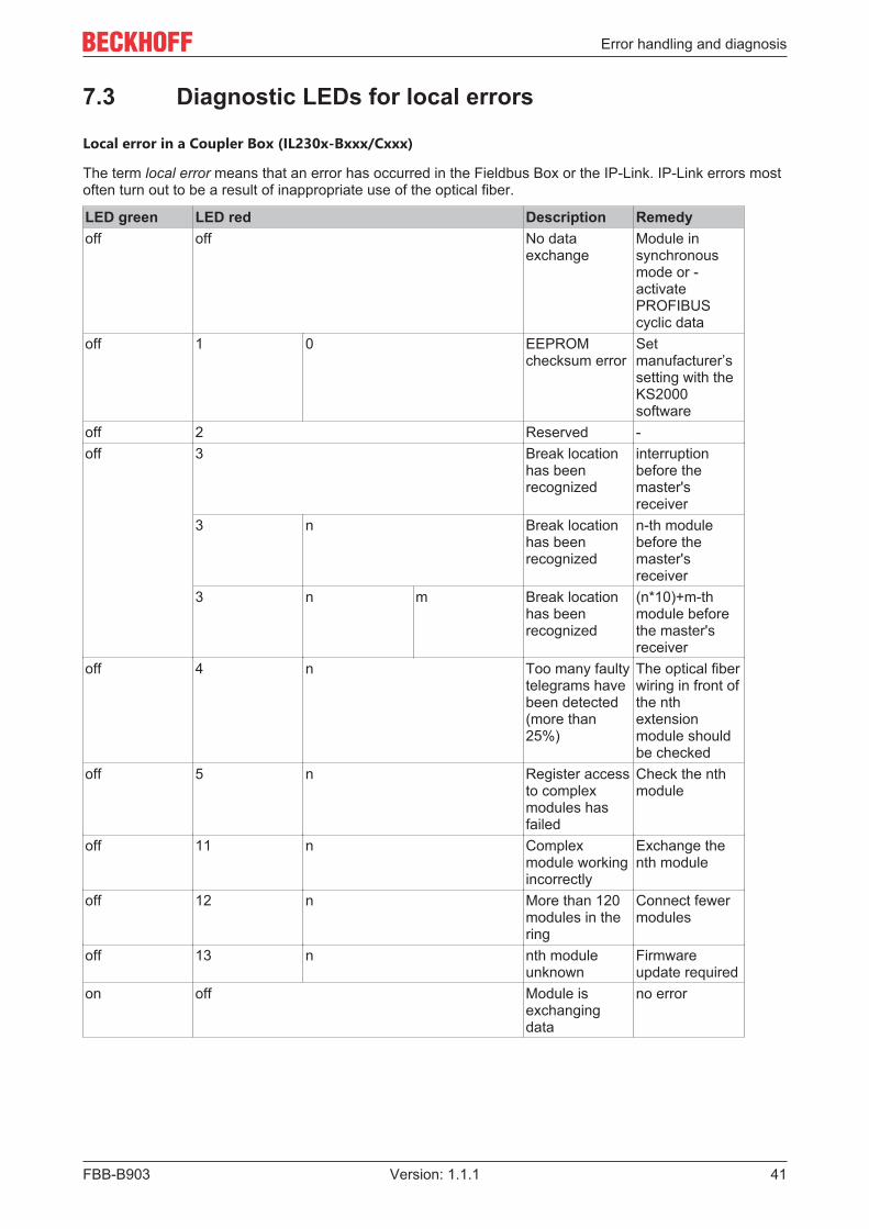
7.3 Diagnostic LEDs for local errors
Local error in a Coupler Box (IL230x-Bxxx/Cxxx)
The term local error means that an error has occurred in the Fieldbus Box or the IP-Link. IP-Link errors mostoften turn out to be a result of inappropriate use of the optical fiber.
LED green LED red Description Remedyoff off No data
exchangeModule insynchronousmode or -activatePROFIBUScyclic data
off 1 0 EEPROMchecksum error
Setmanufacturer’ssetting with theKS2000software
off 2 Reserved -off 3 Break location
has beenrecognized
interruptionbefore themaster'sreceiver
3 n Break locationhas beenrecognized
n-th modulebefore themaster'sreceiver
3 n m Break locationhas beenrecognized
(n*10)+m-thmodule beforethe master'sreceiver
off 4 n Too many faultytelegrams havebeen detected(more than25%)
The optical fiberwiring in front ofthe nthextensionmodule shouldbe checked
off 5 n Register accessto complexmodules hasfailed
Check the nthmodule
off 11 n Complexmodule workingincorrectly
Exchange thenth module
off 12 n More than 120modules in thering
Connect fewermodules
off 13 n nth moduleunknown
Firmwareupdate required
on off Module isexchangingdata
no error
Error handling and diagnosis
FBB-B90342 Version: 1.1.1
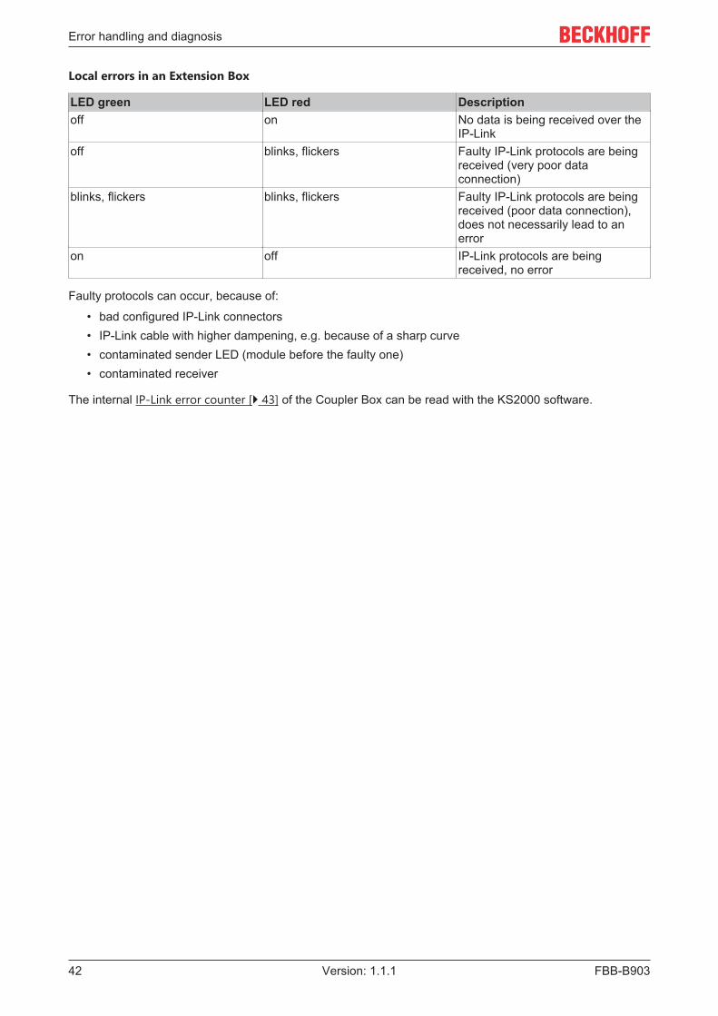
Local errors in an Extension Box
LED green LED red Descriptionoff on No data is being received over the
IP-Linkoff blinks, flickers Faulty IP-Link protocols are being
received (very poor dataconnection)
blinks, flickers blinks, flickers Faulty IP-Link protocols are beingreceived (poor data connection),does not necessarily lead to anerror
on off IP-Link protocols are beingreceived, no error
Faulty protocols can occur, because of:
• bad configured IP-Link connectors• IP-Link cable with higher dampening, e.g. because of a sharp curve• contaminated sender LED (module before the faulty one)• contaminated receiver
The internal IP-Link error counter [} 43] of the Coupler Box can be read with the KS2000 software.

Error handling and diagnosis
FBB-B903 43Version: 1.1.1
7.4 Check of the IP-Link connectionA correct assembled IP-Link cable will assure an error free transmission.
An additional testing of the transmission quality and error diagnostics is possible with the KS2000configuration software.
For this test, the fieldbus master (e.g. a PROFIBUS PC Card) should be on the bus and it should transmitdata cyclical. Another way to generate cyclic data is, to switch the coupler to free running via the KS2000software.
The result should be, that the I/O RUN LED flashes in a bright green. This shows, that a data exchange withthe connected extension boxes takes place. A red blinking I/O ERR LED shows faulty IP-Link telegrams.These faulty telegrams will be repeated automatically like in any other fieldbus system. This way atransmission of the data is guaranteed.
Error counter
Table 90, offset 005 shows possible IP-Link errors. Sporadic appearing errors do not mean any problem forthe communication, as long as they do not reach a critical limit.
This error counter is only reset by the Power ON/OFF.

Error handling and diagnosis
FBB-B90344 Version: 1.1.1
If lots of errors occur in a very short time, this will be interpreted as a heavy disturbance of thecommunication and the coupler box will report this error. This can be seen at offset 006 and 007. Bothvalues will show a value > 200 and the I/O ERR LEDs of the coupler box will blink the according error code.
NoteThe KS2000 Configuration Software communicates with the Coupler Box via the serial channel.The content of the registers will not be refreshed automatically.
Position of the error
In case of an IP-Link error, the Coupler Box tries to read the error location from the register of the ExtensionBox. If the fiber optic ring is interrupted or the communication is heavily disturbed, this is not possible. Onlythe position of the last functioning Extension Box before the receiver of the Coupler Box can be recognized.The box will then flash this error code via the I/O ERR LED.
If the communication via IP-Link is still running, table 87 shows the error counter of each Extension Box.
The offset register corresponds to the position of the Extension Box in the KS2000 tree (left side of graphic).This example shows errors at offset 004 and 006.
In the "real" world the faulty IP-Link telegram was reported from the IE20xx and the IE3112, that means theproblem has to looked for before these modules.
The error can be up to:
• the sending module• the receiving module• the IP-Link cable• the connectors
If there is an error in table 90 and none in table 87, the faulty transmission is between the last Extension Boxand the Coupler Box.

Error handling and diagnosis
FBB-B903 45Version: 1.1.1
In most cases the transmission errors can be traced back to bad configured IP-Link connectors or a too highattenuation of the cable due to sharp bending.
The values of table 87 directly come from the extension boxes. In case of an IP-Link interruption thesevalues will be set to zero and only table 90 can be used.
NoteIf you want to operate a Coupler Box (e.g. IL2300-Bxxx, IL2301-Bxxx or IL2302-Bxxx ) totally with-out Extension Box Modules (IExxxx), you have to connect the send and receive socket of this Cou-pler Box directly by using an IP Link Cable! For this the IP Link Jumper ZK1020-0101-1000 fits per-fect.

Accessories
FBB-B90346 Version: 1.1.1
8 Accessories
8.1 Fieldbus Box accessoriesThe necessary accessories for the Fieldbus Box Modules are also available from Beckhoff in protection classIP67. You may get an overview from the Beckhoff catalog or from our internet pages (http://www.beckhoff.com).
Fieldbus Accessories• Pre-assembled cable• Plug• Distributor
Power supply• Pre-assembled cable• Plug• Distributor
Sensor power supply• Pre-assembled cable• Plug• Distributor
IP-Link• Pre-assembled cable• Plug

Accessories
FBB-B903 47Version: 1.1.1
8.2 Power cables
Ordering data
Order designa-tion
Power lead Screw-inconnector
Contacts Cross-section
Length
ZK2020-3200-0020
Straight socket,open end
M8 4-pin 0.34 mm2 2.00 m
ZK2020-3200-0050
5.00 m
ZK2020-3200-0100
10.00 m
ZK2020-3400-0020
Angled socket,open end
2.00 m
ZK2020-3400-0050
5.00 m
ZK2020-3400-0100
10.00 m
ZK2020-3132-0001
Straight socket,straight socket
0.15 m
ZK2020-3132-0005
0.50 m
ZK2020-3132-0010
1.00 m
ZK2020-3132-0020
2.00 m
ZK2020-3132-0050
5.00 m
ZK2020-3334-0001
Angled socket,angled socket
0.15 m
ZK2020-3334-0005
0.50 m
ZK2020-3334-0010
1.00 m
ZK2020-3334-0020
2.00 m
ZK2020-3334-0050
5.00 m
Further available power cables may be found in the Beckhoff catalog or on our internet pages (http://www.beckhoff.com).
Technical data
Technical dataRated voltage according to IEC60 664-1 60 VAC / 75 VDC
Contamination level according to IEC 60 664-1 3/2Insulation resistance IEC 60 512-2 >109WCurrent carrying capacity according to IEC 60512-3 4 AVolume resistance according to IEC 60512-2 < 5 mWProtection class according to IEC 60529 IP65/66/67, when screwed togetherAmbient temperature -30°C to +80°C

Appendix
FBB-B90348 Version: 1.1.1
9 Appendix
9.1 General operating conditions
Protection degrees (IP-Code)
The standard IEC 60529 (DIN EN 60529) defines the degrees of protection in different classes.
1. Number: dust protectionand touch guard
Definition
0 Non-protected1 Protected against access to hazardous parts with the
back of a hand. Protected against solid foreignobjects of Ø50 mm
2 Protected against access to hazardous parts with afinger. Protected against solid foreign objects ofØ12,5 mm.
3 Protected against access to hazardous parts with atool. Protected against solid foreign objects Ø2,5 mm.
4 Protected against access to hazardous parts with awire. Protected against solid foreign objects Ø1 mm.
5 Protected against access to hazardous parts with awire. Dust-protected. Intrusion of dust is not totallyprevented, but dust shall not penetrate in a quantityto interfere with satisfactory operation of the device orto impair safety.
6 Protected against access to hazardous parts with awire. Dust-tight. No intrusion of dust.
2. Number: water* protection Definition0 Non-protected1 Protected against water drops2 Protected against water drops when enclosure tilted
up to 15°.3 Protected against spraying water. Water sprayed at
an angle up to 60° on either side of the vertical shallhave no harmful effects.
4 Protected against splashing water. Water splashedagainst the disclosure from any direction shall haveno harmful effects
5 Protected against water jets6 Protected against powerful water jets7 Protected against the effects of temporary immersion
in water. Intrusion of water in quantities causingharmful effects shall not be possible when theenclosure is temporarily immersed in water for 30min. in 1 m depth.
*) These protection classes define only protection against water!
Chemical Resistance
The Resistance relates to the Housing of the Fieldbus Box and the used metal parts.

Appendix
FBB-B903 49Version: 1.1.1
Character ResistanceSteam at temperatures >100°C: not resistantSodium base liquor(ph-Value > 12)
at room temperature: resistant> 40°C: not resistant
Acetic acid not resistantArgon (technical clean) resistant
Key
resistant: Lifetime several monthsnon inherently resistant: Lifetime several weeksnot resistant: Lifetime several hours resp. early decomposition

Appendix
FBB-B90350 Version: 1.1.1
9.2 Approvals
Approvals
UL E172151
Conformity mark
CE
Type of protection
IP65/66/67 in accordance with EN60529

Appendix
FBB-B903 51Version: 1.1.1
9.3 Test standards for device testing
EMC
Resistance: EN 61000-6-2
Emission: EN 61000-6-4
Resistance to Vibration
EN 60068-2-2 Vibration test, Amplitude 2 g (Standard 1 g)
EN 60068-2-27 Shock Test, Shock count 1000 (Standard 2)

Appendix
FBB-B90352 Version: 1.1.1
9.4 Support and ServiceBeckhoff and their partners around the world offer comprehensive support and service, making available fastand competent assistance with all questions related to Beckhoff products and system solutions.
Beckhoff's branch offices and representatives
Please contact your Beckhoff branch office or representative for local support and service on Beckhoffproducts!
The addresses of Beckhoff's branch offices and representatives round the world can be found on her internetpages: https://www.beckhoff.com
You will also find further documentation for Beckhoff components there.
Beckhoff Support
Support offers you comprehensive technical assistance, helping you not only with the application ofindividual Beckhoff products, but also with other, wide-ranging services:
• support• design, programming and commissioning of complex automation systems• and extensive training program for Beckhoff system components
Hotline: +49 5246 963 157Fax: +49 5246 963 9157e-mail: [email protected]
Beckhoff Service
The Beckhoff Service Center supports you in all matters of after-sales service:
• on-site service• repair service• spare parts service• hotline service
Hotline: +49 5246 963 460Fax: +49 5246 963 479e-mail: [email protected]
Beckhoff Headquarters
Beckhoff Automation GmbH & Co. KG
Huelshorstweg 2033415 VerlGermany
Phone: +49 5246 963 0Fax: +49 5246 963 198e-mail: [email protected]: https://www.beckhoff.com


Beckhoff Automation GmbH & Co. KGHülshorstweg 2033415 VerlGermanyPhone: +49 5246 [email protected]