Embed Size (px)
Citation preview
DOE/FIU SCIENCE & TECHNOLOGY WORKFORCE DEVELOPMENT PROGRAM
STUDENT SUMMER INTERNSHIP TECHNICAL REPORT For June 16, 2008 to August 22, 2008
Waste Treatment Plant (WTP) –
Pre-Engineering Platform (PEP)
Automated Operation Control via Programmable Logic Controllers (PLC)
Principal Investigators:
Serkan Akar (DOE Fellow Student) Florida International University
Joseph (Jake) Tucker, Sr. Engineer, Mentor Pacific Northwest National Laboratory
Acknowledgements:
Gary Josephson Manager
David Clark, Programming Engineer
Florida International University Collaborator:
Leonel E. Lagos, Ph.D., PMP®
Prepared for:
U.S. Department of Energy Office of Environmental Management
Under Grant No. DE-FG01-05EW07033
ARC-2008-D2540-04-012
i i
DISCLAIMER
This report was prepared as an account of work sponsored by an agency of the United
States government. Neither the United States government nor any agency thereof, nor any
of their employees, nor any of its contractors, subcontractors, nor their employees makes
any warranty, express or implied, or assumes any legal liability or responsibility for the
accuracy, completeness, or usefulness of any information, apparatus, product, or process
disclosed, or represents that its use would not infringe upon privately owned rights.
Reference herein to any specific commercial product, process, or service by trade name,
trademark, manufacturer, or otherwise does not necessarily constitute or imply its
endorsement, recommendation, or favoring by the United States government or any other
agency thereof. The views and opinions of authors expressed herein do not necessarily
state or reflect those of the United States government or any agency thereof.
ARC-2008-D2540-04-012
ii ii
ABSTRACT
A programmable logic controller (PLC) is a digitalized computer system used primarily
for the automation of industrial processes. There are various types of PLC models
commercially available and the main purpose of the PLCs are to allow operation from a
computer screen or to automatically control the operations. PLCs are designed for
multiple inputs and outputs, extended temperature ranges, immunity to electrical noise,
and resistance to vibration and impact.
PLCs are utilized in the pre-treatment engineering platform (PEP), which is a scaled
mock-up model of a waste treatment plant (WTP). PEP was developed to enhance the
treatment system by controlling operations through a computer. All of the machinery in
the PEP are controlled via PLCs. The control system consists of multiple PLCs (typically
one per skid) networked to a common control station in a central control room (CCR).
ARC-2008-D2540-04-012
iii iii
TABLE OF CONTENTS
Abstract ii
Table of Contents iii
List of Figures iv
1. Introduction 1
2. Executive Summary 2
3. Task Description 3
4. Results 11
5. References 12
6. Appendix A 13
ARC-2008-D2540-04-012
1 1
1. INTRODUCTION
The Department of Energy (DOE) has developed a waste treatment plant (WTP) program
to improve the safe storage of high level waste (HLW). One storage site for HLW is
Hanford, WA. However, due to the limited storage space available and issues with the
existing storage tanks, improvements in the management and storage of HLW are needed.
Dedicated scientists and engineers at Hanford have developed a new method for treating
and storing the waste. This new technique is used within the WTP to treat and vitrify
radioactive waste stored in the underground tanks at the Hanford site. The treatment plant
is designed to separate the HLW from the low activity waste (LAW), which is done via
ultra filtration. The remaining concentrated HLW then undergoes a caustic and oxidative
leaching process. This process helps to dissolve and eliminate any material that might
limit the HLW loading into the stationary waste glass (e.g., aluminum, chromium,
phosphates, and sulfates). All of these processes are repeated until the pre-treatment
obtains a highly concentrated HLW.
Since this new method is theoretical, it needs to be thoroughly tested. Therefore, a
pretreatment engineering platform (PEP), a mock-up scaled platform, was established to
perform demonstrations and tests before a full-size treatment system is built on the site.
The PEP’s operations are controlled with programmable logic controllers (PLCs). The
mock-up scale-model is constructed on seven skids (divisions) with each skid being
responsible for a certain task within the PEP project. The skids are named P1 through P7,
U1 and U2. For each skid, there is a corresponding PLC central processing unit (CPU) to
ensure that the programmed operation is being performed. The PLCs are integrated with a
Human Machine Interface (HMI) to allow users to perform operations, to do necessary
programming-based troubleshooting from a computer, and to monitor all the functions
being executed.
In addition to the PLCs that were already installed at the Process Development
Laboratory (PDL), a test bed consisting of PLC CPUs was set up in the Mechanical CAD
Laboratory where software updates are programmed and new engineers are trained.
ARC-2008-D2540-04-012
2 2
2. EXECUTIVE SUMMARY
This summer internship research work has been supported by the DOE/FIU Science &
Technology Workforce Initiative, an innovative program developed by the U.S.
Department of Energy’s Environmental Management (DOE-EM) and Florida
International University’s Applied Research Center (FIU-ARC). During the summer of
2008, an FIU-ARC student spent 10 weeks interning at the Pacific Northwest National
Laboratory (PNNL) in Richland, Washington, under the supervision and guidance of Dr.
Gary Josephson and Senior Engineer Joseph (Jake) Tucker.
PLC systems that control all of the functions of the mock-up scale WTP project were
studied in the Mechanical CAD Laboratory. A test bed that contains a set of PLCs, an
exact imitation of what is installed at the PDL-West building, was established at the
laboratory. PLCs ensure the automation of the programmed functions, such as motor
operation, temperature, pressure, flow sensing, etc. In addition, a PLC is capable of
comparing the values from the system and the written program, taking the necessary
corrective action without human interference.
ARC-2008-D2540-04-012
3 3
3. TASK DESCRIPTION
PLCs are the brain of the PEP. PLCs ensure the automation of the mock-up scaled WTP
project by taking measurements and processing the received data. The control system
consists of multiple PLC units (typically one unit per skid) networked to a common
control station in a central control room (CCR). One complete unit is shown in Figure 1.
A PLC is made of the following 2 main parts and subparts:
1. Hardware
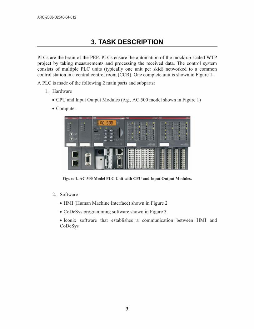
• CPU and Input Output Modules (e.g., AC 500 model shown in Figure 1)
• Computer
Figure 1. AC 500 Model PLC Unit with CPU and Input Output Modules.
2. Software
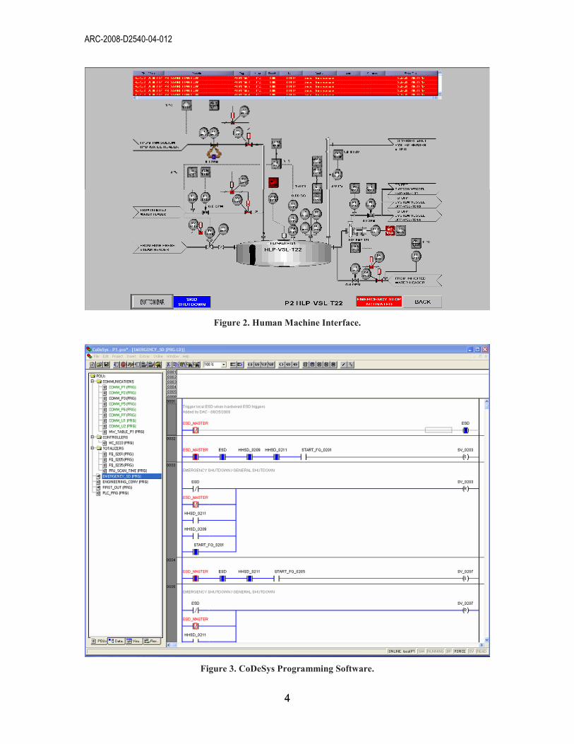
• HMI (Human Machine Interface) shown in Figure 2
• CoDeSys programming software shown in Figure 3
• Iconix software that establishes a communication between HMI and CoDeSys
ARC-2008-D2540-04-012
4 4
Figure 2. Human Machine Interface.
Figure 3. CoDeSys Programming Software.

ARC-2008-D2540-04-012
5 5
The PLC hardware, along with its modules, are installed on the PEP and the sensor gages,
motors and flow meters are wired to the input and output modules. The computer is
where all the software is installed and operations are monitored. The HMI gives a visual
image of all the equipment that is connected to the PLC’s central processing unit (CPU)
and the operations being executed. The HMI is connected to the programming software
CoDeSys via Iconix software. CoDeSys is where the PLC codes are generated and
compiled. CoDeSys software communicates with the CPU via the HMI; the Iconix
software establishes a connection between the two. The connection scheme is shown in
Figure 4. Once the program is generated, it can be stored in the CPU and ran without
further interaction unless an update or correction needs to be made. One other advantage
of using a PLC is to gain remote access via a modem connection. A user can log into
system from anywhere and monitor all the operation once the modem connection is
established. This feature is further explained in Appendix A.
OPC Client
OPC Server
PS501
Switch
AC500
Serielle Verbindung
(optional)
OPC Client
Figure 4. Connection scheme.
In order to minimize conflicts between points of operation, the following operational
philosophy is applied:
• All PLCs (HMI) can view all systems.
• Each local skid PLC can only control equipment associated with that skid (e.g.,
the start vessel agitator).
• The common control station in the CCR can control all operations (e.g., inter-skid
transfers).

ARC-2008-D2540-04-012
6 6
The PEP has 2 types of operations that are controlled by the PLC and many sub-
operations within the main ones, as follows:
a. Primary Operations
1. Simulant Feed Receipt
2. Caustic Leaching
3. Solids Concentration
4. Caustic Leaching
5. Re-concentration
6. First Solids Washing
7. Oxidative Leaching
8. Final Solids Washing
9. Solids Transfer
10. Filter Washing
11. Filter Cleaning
b. Support Operations:
1. Receipt/Stage
2. Sampling
3. Dilution
4. Mixing (Pump Recirculation, Pulse Jet Mixers (PJMs), Spargers)
5. Mixing (in-line)
6. Heating
7. Cooling
8. Reagent Addition
9. Transfer
10. Line Flushing
11. Filter Back-pulsing
12. Control
• Pressure
• Flow (Instantaneous and Totalized)
• Temperature
• Level
• Density

ARC-2008-D2540-04-012
7 7
In Figure 5, a simplified flow diagram of the progress is shown.
Figure 5. Simplified flow diagram for the pretreatment engineering platform.
ARC-2008-D2540-04-012
8 8
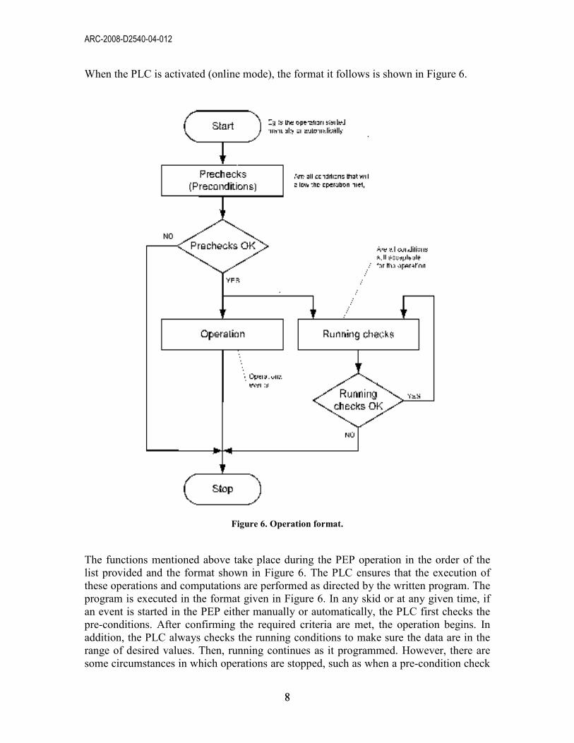
When the PLC is activated (online mode), the format it follows is shown in Figure 6.
Figure 6. Operation format.
The functions mentioned above take place during the PEP operation in the order of the
list provided and the format shown in Figure 6. The PLC ensures that the execution of
these operations and computations are performed as directed by the written program. The
program is executed in the format given in Figure 6. In any skid or at any given time, if
an event is started in the PEP either manually or automatically, the PLC first checks the
pre-conditions. After confirming the required criteria are met, the operation begins. In
addition, the PLC always checks the running conditions to make sure the data are in the
range of desired values. Then, running continues as it programmed. However, there are
some circumstances in which operations are stopped, such as when a pre-condition check
ARC-2008-D2540-04-012
9 9
fails or when the running check value goes out of range. This is a crucial format that PLC
has to follow to guarantee desired operation performance.
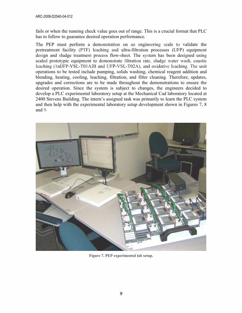
The PEP must perform a demonstration on an engineering scale to validate the
pretreatment facility (PTF) leaching and ultra-filtration processes (UFP) equipment
design and sludge treatment process flow-sheet. The system has been designed using
scaled prototypic equipment to demonstrate filtration rate, sludge water wash, caustic
leaching (1nlJFP-VSL-T01AIB and UFP-VSL-T02A), and oxidative leaching. The unit
operations to be tested include pumping, solids washing, chemical reagent addition and
blending, heating, cooling, leaching, filtration, and filter cleaning. Therefore, updates,
upgrades and corrections are to be made throughout the demonstrations to ensure the
desired operation. Since the system is subject to changes, the engineers decided to
develop a PLC experimental laboratory setup at the Mechanical Cad laboratory located at
2400 Stevens Building. The intern’s assigned task was primarily to learn the PLC system
and then help with the experimental laboratory setup development shown in Figures 7, 8
and 9.
Figure 7. PEP experimental lab setup.
ARC-2008-D2540-04-012
10 10
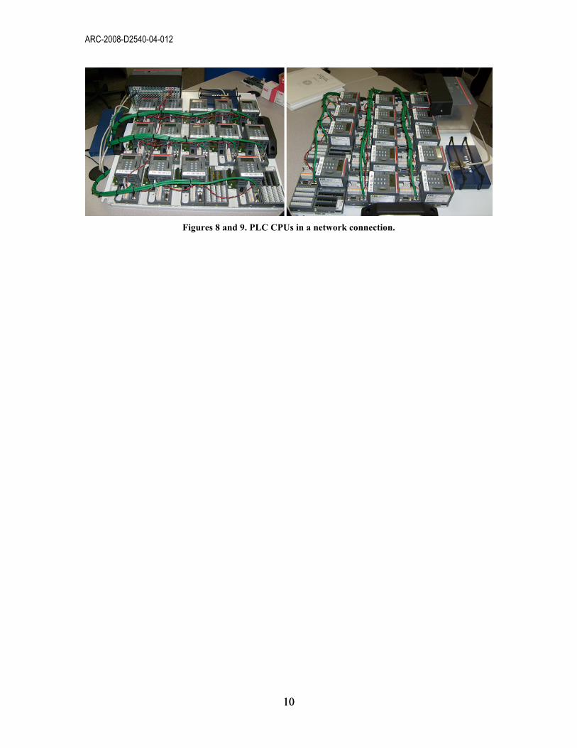
Figures 8 and 9. PLC CPUs in a network connection.
ARC-2008-D2540-04-012
11 11
4. RESULTS
As the intern had no experience with PLCs, his primary objective was to gain familiarity
with the system. This process began with reading manuals and performing basic research
on PLCs. The main questions that had to be answered before beginning work with the
PLCs included the following: What is a PLC? How does it work? What project is it being
used for? What does it control? The intern successfully accomplished this basic research
and gained an essential understanding of the PLC technology.
The system used on the PEP project is an ABB brand AC 500 model and uses
programming with PLC software CoDeSys. Engineers at the PEP struggled with the
communication between the computer and the PLC. Due to the lack of customer
assistance or technical support from the ABB company, someone had to dedicate
sufficient time to read all of the technology documentation, perform research into how
PEP works and define the requirements. Since the project was running behind, the
scientists and engineers could dedicate very little time specifically to the PLC. Thus, the
intern dedicated all of his internship hours specifically to the PLC. The intern
successfully established a connection and set up the experimental PLC platform at the
laboratory where programming engineers and operation engineers could use the system,
correct mistakes, or diagnose the cause of a failed operation. Figure 7 shows a view of the
system after the intern successfully completed his task.
ARC-2008-D2540-04-012
12 12
5. REFERENCES
1. http://www.hightech.com.au/PLC.htm)
2. Evan Dresel, 2008, Site Integration Testing Plan for the Pretreatment Engineering Platform Water Testing, Pacific Northwest National Laboratory
(PNNL), Richland, WA 99352.
3. Scott Lehrman, 2008, Platform PEP Phase 1 Testing Process Description, PNNL, WA.
ARC-2008-D2540-04-012
13 13
APPENDIX A REMOTE PROGRAMMING OF KT95…98 AND AC500
1. KT95...98 using AC1131 14
1.1 Modem 14
1.2 Cable PC �� modem1 14
1.3 Cable modem 2 �� PLC 14
1.4 Parameter settings modem 1 (PC side) 15
1.5 Parameter settings modem 2 (PLC side) 15
1.6 Use of Microsoft tool „Hyperterminal“ 16
2. AC500 using PS501 (CodeSys) 16
2.1 Modem 17
2.2 Cable PC �� modem 1 17
2.3 Cable modem2 �� PLC 17
2.4 Parameter settings modem 1 (PC side) 17
2.5 Parameter settings modem 2 (PLC side) 18
2.6 Use of Microsoft tool „Hyperterminal“ 19
ARC-2008-D2540-04-012
14 14
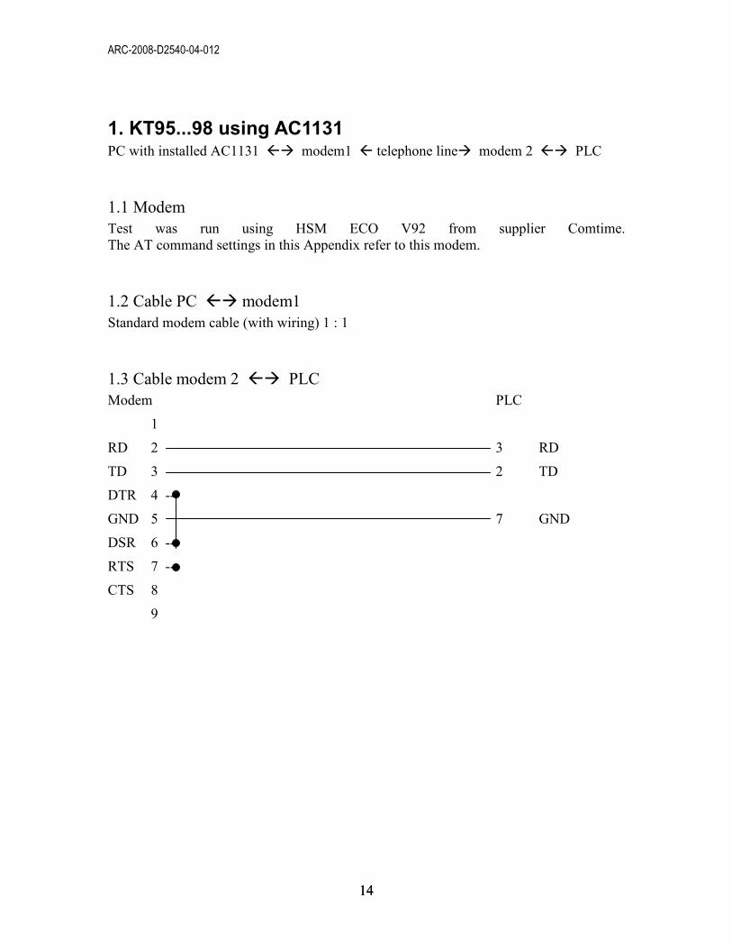
1. KT95...98 using AC1131 PC with installed AC1131 �� modem1 � telephone line� modem 2 �� PLC
1.1 Modem
Test was run using HSM ECO V92 from supplier Comtime.
The AT command settings in this Appendix refer to this modem.
1.2 Cable PC �� modem1
Standard modem cable (with wiring) 1 : 1
1.3 Cable modem 2 �� PLC
Modem PLC
1
RD 2 3 RD
TD 3 2 TD
DTR 4 --
GND 5 7 GND
DSR 6 --
RTS 7 --
CTS 8
9
ARC-2008-D2540-04-012
15 15
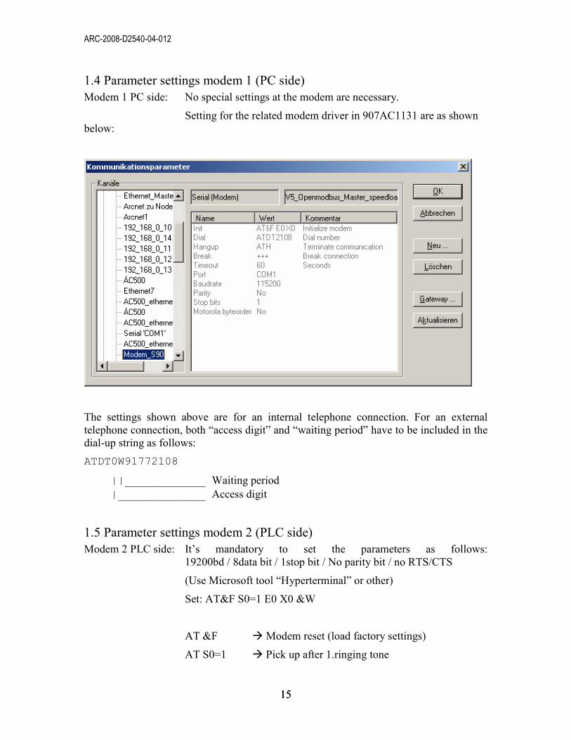
1.4 Parameter settings modem 1 (PC side)
Modem 1 PC side: No special settings at the modem are necessary.
Setting for the related modem driver in 907AC1131 are as shown
below:
The settings shown above are for an internal telephone connection. For an external
telephone connection, both “access digit” and “waiting period” have to be included in the
dial-up string as follows:
ATDT0W91772108
||____________ Waiting period
|_____________ Access digit
1.5 Parameter settings modem 2 (PLC side)
Modem 2 PLC side: It’s mandatory to set the parameters as follows:
19200bd / 8data bit / 1stop bit / No parity bit / no RTS/CTS
(Use Microsoft tool “Hyperterminal” or other)
Set: AT&F S0=1 E0 X0 &W
AT &F � Modem reset (load factory settings)
AT S0=1 � Pick up after 1.ringing tone
ARC-2008-D2540-04-012
16 16
AT E0 � Echo off in command mode
AT X0 � Modem to respond with CONNECT
AT &W � Saving of active profile
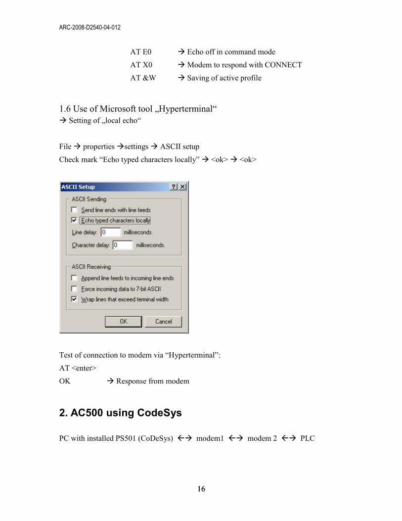
1.6 Use of Microsoft tool „Hyperterminal“
� Setting of „local echo“
File � properties �settings � ASCII setup
Check mark “Echo typed characters locally” � <ok> � <ok>
Test of connection to modem via “Hyperterminal”:
AT <enter>
OK � Response from modem
2. AC500 using CodeSys
PC with installed PS501 (CoDeSys) �� modem1 �� modem 2 �� PLC
ARC-2008-D2540-04-012
17 17
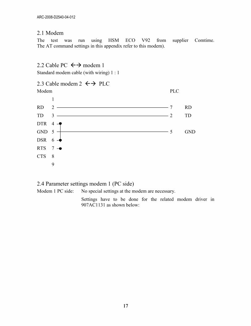
2.1 Modem
The test was run using HSM ECO V92 from supplier Comtime.
The AT command settings in this appendix refer to this modem).
2.2 Cable PC �� modem 1
Standard modem cable (with wiring) 1 : 1
2.3 Cable modem 2 �� PLC
Modem PLC
1
RD 2 7 RD
TD 3 2 TD
DTR 4 --
GND 5 5 GND
DSR 6 --
RTS 7 --
CTS 8
9
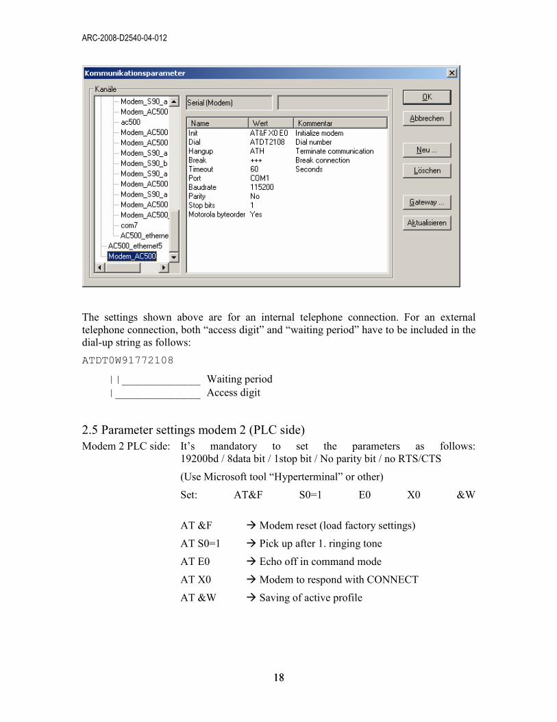
2.4 Parameter settings modem 1 (PC side)
Modem 1 PC side: No special settings at the modem are necessary.
Settings have to be done for the related modem driver in
907AC1131 as shown below:
ARC-2008-D2540-04-012
18 18
The settings shown above are for an internal telephone connection. For an external
telephone connection, both “access digit” and “waiting period” have to be included in the
dial-up string as follows:
ATDT0W91772108
||____________ Waiting period
|_____________ Access digit
2.5 Parameter settings modem 2 (PLC side)
Modem 2 PLC side: It’s mandatory to set the parameters as follows:
19200bd / 8data bit / 1stop bit / No parity bit / no RTS/CTS
(Use Microsoft tool “Hyperterminal” or other)
Set: AT&F S0=1 E0 X0 &W
AT &F � Modem reset (load factory settings)
AT S0=1 � Pick up after 1. ringing tone
AT E0 � Echo off in command mode
AT X0 � Modem to respond with CONNECT
AT &W � Saving of active profile
ARC-2008-D2540-04-012
19 19
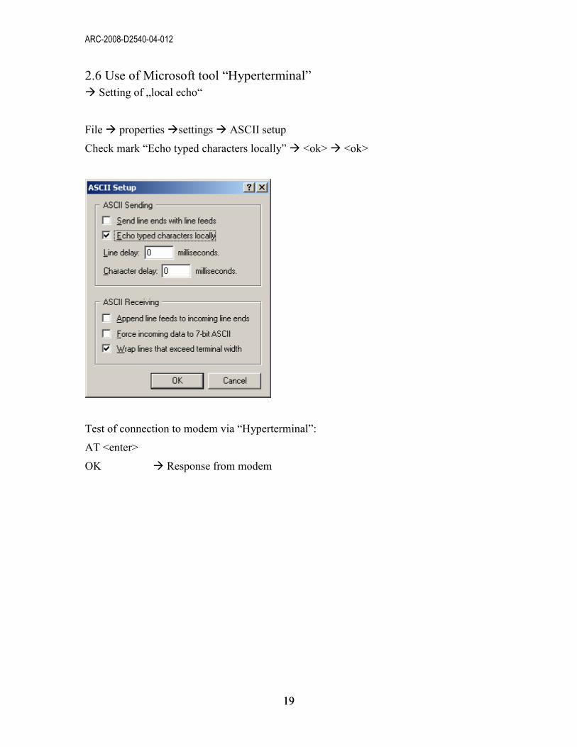
2.6 Use of Microsoft tool “Hyperterminal”
� Setting of „local echo“
File � properties �settings � ASCII setup
Check mark “Echo typed characters locally” � <ok> � <ok>
Test of connection to modem via “Hyperterminal”:
AT <enter>
OK � Response from modem