Embed Size (px)
Citation preview
DOEPFER System A-100 Synthesizer Voice A-111-5
1
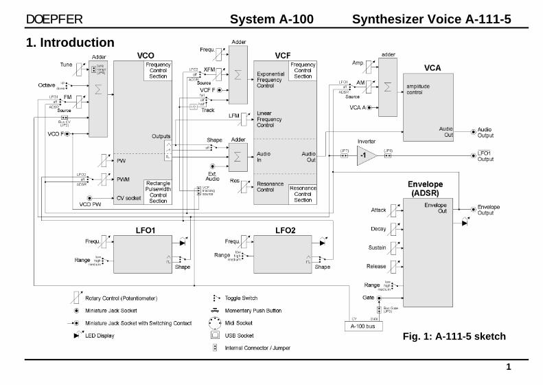
Fig. 1: A-111-5 sketch
1. Introduction

Synthesizer Voice A-111-5 System A-100 DOEPFER
2
Module A-111-5 is a complete monophonic synthesizer module that includes these components: VCO
• manual tune control (with an internal jumper the range can be set to ~ +/-1 half an octave or ~ +/-2.5 octaves)
• range switch -1 / 0 / +1 octave • frequency range about 10Hz ... 12kHz • FM (frequency modulation) control with modulation
source switch (LFO1 / off / ADSR) • manual pulsewidth control for rectangle waveform • PWM control with modulation source switch (LFO2 / off
/ ADSR) • waveform switch (sawtooth / off / triangle) • the sum of the waveform chosen by this switch and the
rectangle is fed into the VCF (to turn the rectangle off the PW control has to be set fully CCW)
• external CV input for VCO frequency (1V/octave) • external CV input for external PWM of the rectangle • internal CV input for frequency (1V/octave) connected
to the A-100 bus via jumper, the jumper can be used to interrupt this internal connection if not wanted
VCF
• 24 dB low pass • ~ 12 octaves frequency range • manual frequency control • tracking switch half - off - full (internally connected to
the external frequency CV input of the VCO, i.e. the VCF tracks to the VCO if the switch is set to "half" or "full" position)
• XM: exponential FM (frequency modulation) control with modulation source switch (LFO2 / off / ADSR)
• LM: linear FM (frequency modulation) control to modulate the VCF by the triangle of the VCO in a linear (!) manner
• manual resonance control (up to self oscillation) • external audio input (this signal is added to the VCO
signal) • external CV input for filter frequency • 1V/octave tracking for usage of the VCF as a sine
wave oscillator (not as precise as the VCO but much better than most of the other filters)
DOEPFER System A-100 Synthesizer Voice A-111-5
3
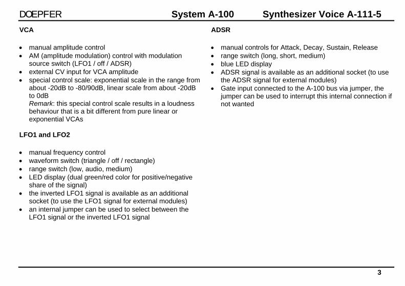
VCA • manual amplitude control • AM (amplitude modulation) control with modulation
source switch (LFO1 / off / ADSR) • external CV input for VCA amplitude • special control scale: exponential scale in the range from
about -20dB to -80/90dB, linear scale from about -20dB to 0dB Remark: this special control scale results in a loudness behaviour that is a bit different from pure linear or exponential VCAs
LFO1 and LFO2 • manual frequency control • waveform switch (triangle / off / rectangle) • range switch (low, audio, medium) • LED display (dual green/red color for positive/negative
share of the signal) • the inverted LFO1 signal is available as an additional
socket (to use the LFO1 signal for external modules) • an internal jumper can be used to select between the
LFO1 signal or the inverted LFO1 signal
ADSR • manual controls for Attack, Decay, Sustain, Release • range switch (long, short, medium) • blue LED display • ADSR signal is available as an additional socket (to use
the ADSR signal for external modules) • Gate input connected to the A-100 bus via jumper, the
jumper can be used to interrupt this internal connection if not wanted
Synthesizer Voice A-111-5 System A-100 DOEPFER
4
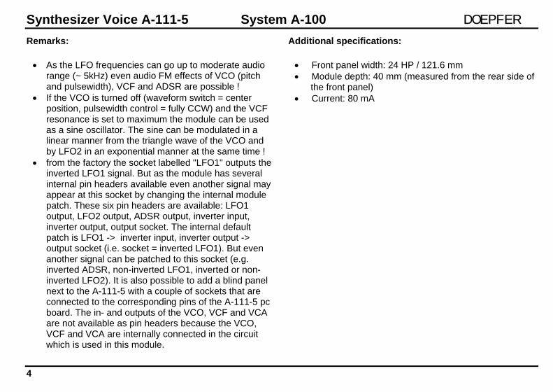
Remarks:
• As the LFO frequencies can go up to moderate audio range (~ 5kHz) even audio FM effects of VCO (pitch and pulsewidth), VCF and ADSR are possible !
• If the VCO is turned off (waveform switch = center position, pulsewidth control = fully CCW) and the VCF resonance is set to maximum the module can be used as a sine oscillator. The sine can be modulated in a linear manner from the triangle wave of the VCO and by LFO2 in an exponential manner at the same time !
• from the factory the socket labelled "LFO1" outputs the inverted LFO1 signal. But as the module has several internal pin headers available even another signal may appear at this socket by changing the internal module patch. These six pin headers are available: LFO1 output, LFO2 output, ADSR output, inverter input, inverter output, output socket. The internal default patch is LFO1 -> inverter input, inverter output -> output socket (i.e. socket = inverted LFO1). But even another signal can be patched to this socket (e.g. inverted ADSR, non-inverted LFO1, inverted or non-inverted LFO2). It is also possible to add a blind panel next to the A-111-5 with a couple of sockets that are connected to the corresponding pins of the A-111-5 pc board. The in- and outputs of the VCO, VCF and VCA are not available as pin headers because the VCO, VCF and VCA are internally connected in the circuit which is used in this module.
Additional specifications:
• Front panel width: 24 HP / 121.6 mm • Module depth: 40 mm (measured from the rear side of
the front panel) • Current: 80 mA
DOEPFER System A-100 Synthesizer Voice A-111-5
5
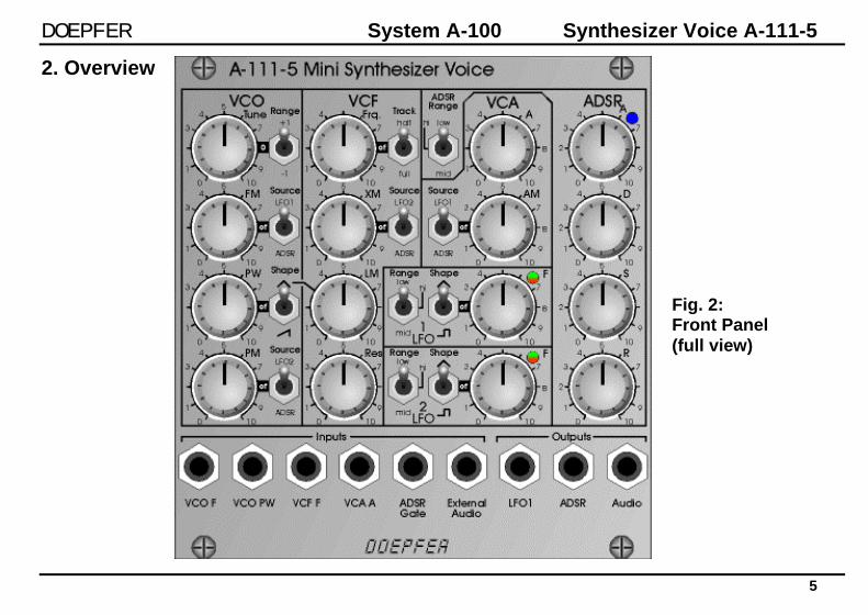
2. Overview
Fig. 2: Front Panel (full view)

Synthesizer Voice A-111-5 System A-100 DOEPFER
6
1
Fig. 2a: Front Panel (VCO and VCF) 1 VCO Tune 2 VCO Range Switch (Octave Switch) 3a VCO FM Source Switch 3b VCO FM Level 4 VCO Waveshape Switch 5 VCO Rectangle Pulsewidth 6a VCO Pulsewidth Modulation Source 6b VCO Pulsewidth Modulation Level 7 VCF Frequency 8 VCF Tracking Switch 9a VCF exponential FM Source Switch 9b VCF exponential FM Level 10 VCF linear FM Level 11 VCF Resonance
2
3b
3a
5
4
6b
6a
7
9a
8
9b
10
11
DOEPFER System A-100 Synthesizer Voice A-111-5
7
16 17
12
13a 18
13b
14c 19
14a 14b
15c 20
15a
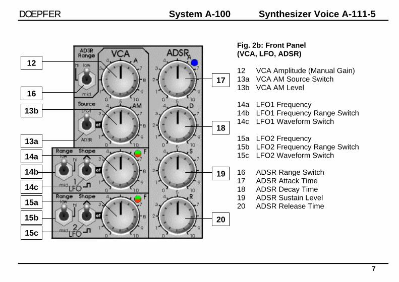
Fig. 2b: Front Panel (VCA, LFO, ADSR) 12 VCA Amplitude (Manual Gain) 13a VCA AM Source Switch 13b VCA AM Level 14a LFO1 Frequency 14b LFO1 Frequency Range Switch 14c LFO1 Waveform Switch 15a LFO2 Frequency 15b LFO2 Frequency Range Switch 15c LFO2 Waveform Switch 16 ADSR Range Switch 17 ADSR Attack Time 18 ADSR Decay Time 19 ADSR Sustain Level 20 ADSR Release Time
15b
Synthesizer Voice A-111-5 System A-100 DOEPFER
8
1
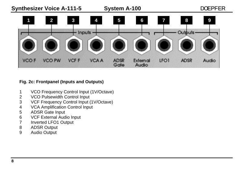
Fig. 2c: Frontpanel (Inputs and Outputs) 1 VCO Frequency Control Input (1V/Octave) 2 VCO Pulsewidth Control Input 3 VCF Frequency Control Input (1V/Octave) 4 VCA Amplification Control Input 5 ADSR Gate Input 6 VCF External Audio Input 7 Inverted LFO1 Output 8 ADSR Output 9 Audio Output
2 3 4 5 6 7 8 9
DOEPFER System A-100 Synthesizer Voice A-111-5
9
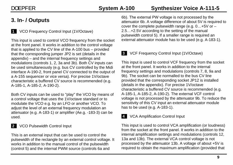
3. In- / Outputs 1 VCO Frequency Control Input (1V/Octave) This input is used to control VCO frequency from the socket at the front panel. It works in addition to the control voltage that is applied to the CV line of the A-100 bus – provided that the corresponding jumper JP2 is set (details in the appendix) – and the internal frequency settings and modulations (controls 1, 2, 3a and 3b). Both CV inputs can be used simultaneously (e.g. bus CV controlled by the Midi interface A-190-2, front panel CV connected to the output of a A-155 sequencer or vice versa). For precise 1V/octave characteristic a buffered CV source is recommended (e.g. A-185-1, A-185-2, A-190-2). Both CV inputs can be used to "play" the VCO by means of a control voltage that uses the 1V/octave standard or to modulate the VCO e.g. by an LFO or another VCO. To adjust the level of an external frequency modulation an attenuator (e.g. A-183-1) or amplifier (Ae.g. -183-3) can be used. 2 VCO Pulsewidth Control Input This is an external input that can be used to control the pulsewidth of the rectangle by an external control voltage. It works in addition to the manual control of the pulsewidth (control 5) and the internal PWM source (controls 6a and
6b). The external PW voltage is not processed by the attenuator 6b. A voltage difference of about 5V is required to cover the complete pulsewidth range (e.g. 0…+5V or –2.5…+2.5V according to the setting of the manual pulsewidth control 5). If a smaller range is required an external attenuator module has to be used (e.g. A-183-1). 3 VCF Frequency Control Input (1V/Octave) This input is used to control VCF frequency from the socket at the front panel. It works in addition to the internal frequency settings and modulations (controls 7, 8, 9a and 9b). The socket can be normalled to the bus CV line provided that the corresponding socket JP12 is installed (details in the appendix). For precise 1V/octave characteristic a buffered CV source is recommended (e.g. A-185-1, A-185-2, A-190-2). The external VCF control voltage is not processed by the attenuator 9b. To reduce the sensitivity of this CV input an external attenuator module has to be used (e.g. A-183-1). 4 VCA Amplification Control Input This input is used to control VCA amplification (or loudness) from the socket at the front panel. It works in addition to the internal amplification settings and modulations (controls 12, 13a and 13b). The external VCA control voltage is not processed by the attenuator 13b. A voltage of about +5V is required to obtain the maximum amplification (provided that

Synthesizer Voice A-111-5 System A-100 DOEPFER
10
controls 12 and 13b are fully CCW). To reduce the sensitivity of this CV input an external attenuator module has to be used (e.g. A-183-1). 5 ADSR Gate Input This input is used to trigger the envelope generator (ADSR). A trigger voltage between +5V and +12V is required to trigger the envelope. The socket can be normalled to the bus gate line provided that the corresponding socket JP3 is installed (details in the appendix). 6 VCF External Audio Input This is an external audio input that is added to the internal VCO signal. E.g. a noise generator, a second VCO or any other audio source can be used. The signal is processed by the VCF and the VCA of the A-111-5 module. The input sensitivity is about 1V. If the signal distorts the usage of an attenuator is recommended (e.g. A-183-1). If the external audio signal is too small an additional amplifier can be used (e.g. A-183-3) to increase the level. 7 Inverted LFO1 Output By default the inverted LFO1 signal is available at this socket. It can be used to control other A-100 modules or other inputs of the A-111-5 (e.g. controlling the PW or the VCF frequency by LFO1). The internal jumpers (JP7, JP8, JP9, JP10) of the module can be set in another way so that
a different signal appears at this socket (details in the appendix). They can be used to control other A-100 modules. 8 ADSR Output This socket outputs the ADSR signal. It can be used to control other A-100 modules. 9 Audio Output This is the audio output of the module. The typical output level is 1V.
DOEPFER System A-100 Synthesizer Voice A-111-5
11
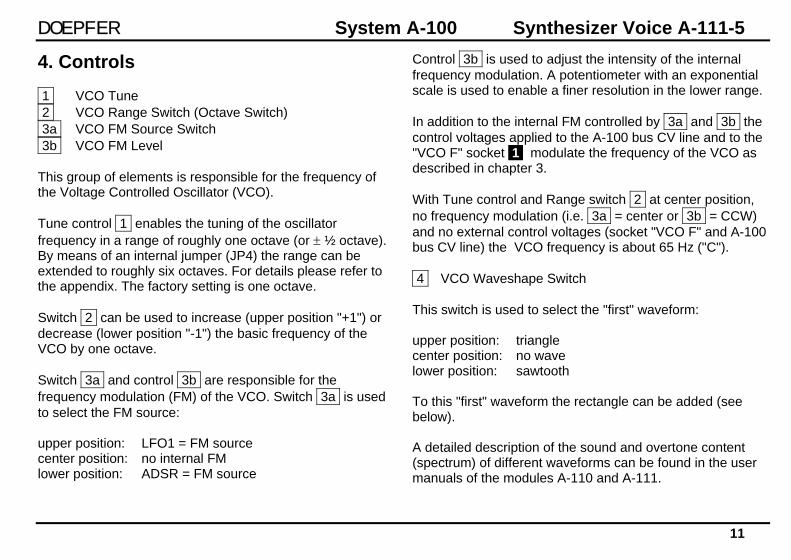
4. Controls 1 VCO Tune 2 VCO Range Switch (Octave Switch) 3a VCO FM Source Switch 3b VCO FM Level This group of elements is responsible for the frequency of the Voltage Controlled Oscillator (VCO). Tune control 1 enables the tuning of the oscillator frequency in a range of roughly one octave (or ± ½ octave). By means of an internal jumper (JP4) the range can be extended to roughly six octaves. For details please refer to the appendix. The factory setting is one octave. Switch 2 can be used to increase (upper position "+1") or decrease (lower position "-1") the basic frequency of the VCO by one octave. Switch 3a and control 3b are responsible for the frequency modulation (FM) of the VCO. Switch 3a is used to select the FM source: upper position: LFO1 = FM source center position: no internal FM lower position: ADSR = FM source
Control 3b is used to adjust the intensity of the internal frequency modulation. A potentiometer with an exponential scale is used to enable a finer resolution in the lower range. In addition to the internal FM controlled by 3a and 3b the control voltages applied to the A-100 bus CV line and to the "VCO F" socket 1 modulate the frequency of the VCO as described in chapter 3. With Tune control and Range switch 2 at center position, no frequency modulation (i.e. 3a = center or 3b = CCW) and no external control voltages (socket "VCO F" and A-100 bus CV line) the VCO frequency is about 65 Hz ("C"). 4 VCO Waveshape Switch This switch is used to select the "first" waveform: upper position: triangle center position: no wave lower position: sawtooth To this "first" waveform the rectangle can be added (see below). A detailed description of the sound and overtone content (spectrum) of different waveforms can be found in the user manuals of the modules A-110 and A-111.

Synthesizer Voice A-111-5 System A-100 DOEPFER
12
5 VCO Rectangle Pulsewidth 6a VCO Pulsewidth Modulation Source 6b VCO Pulsewidth Modulation Level This group of elements is responsible for the additional rectangle wave ("second" waveform) that can be added to the waveform chosen by switch 4 . Control 5 is used adjust the pulsewidth of the rectangle manually. In the center position the pulsewidth is about 50% (provided that no Pulsewidth Modulation is active). In the fully CCW (or fully CW) position the rectangle wave is "off". This position has to be chosen if only triangle or sawtooth is desired as VCO waveform. The pulsewidth adjusted by control 5 can be modulated by means of the switch 6a and control 6b . This function is called Pulsewidth Modulation (PWM) and used to obtain a fatter sound (especially if a slow triangle is used for the modulation) or for other sound effects. Switch 6a is used to select the PWM source: upper position: LFO2 = PWM source center position: no internal PWM lower position: ADSR = PWM source Control 6b is used to adjust the intensity of the internal pulsewidth modulation.
Pay attention that the rectangle waveform can be turned off also by means of the PWM. If for example the manual control 5 can is set to position 2 or 8, LFO2 (triangle) is used as PMW source the rectangle wavform will disappear periodically if the PWM level control 6b is increased beyond a certain position. Same applies if ADSR is used but in this case the disappearance is controlled by the ADSR signal. If the rectangle waveform of LFO2 is chosen, the VCO rectangle can be turned "off" and "on" periodically with the frequency of LFO2. In addition to the internal PW/PWM controlled by 5 , 6a and 6b the control voltage applied to the "VCO PW" socket 2 modulates the pulsewidth of the VCO rectangle waveform as described in chapter 3.
DOEPFER System A-100 Synthesizer Voice A-111-5
13
7 VCF Frequency 8 VCF Tracking Switch 9a VCF exponential FM Source Switch 9b VCF exponential FM Level 10 VCF linear FM Level This group of elements is responsible for the frequency of the Voltage Controlled Filter (VCF). A 24dB Low Pass Filter with adjustable resonance is used in the module. In addition the filter features linear frequency modulation. A detailed description of different filter types can be found in the user manuals of the A-100 filter modules (e.g. A-120 or A-121). Frequency control 7 adjusts the frequency of the filter manually over ~ 12 octaves ( ~ 5Hz ... 20 kHz). Switch 8 can be used to add the control voltage applied to the VCO also to the VCF. This function is called filter tracking because the VCF tracks to the VCO: upper position: half tracking center position: no tracking lower position: full tracking If no tracking is selected the sound character becomes darker as the VCO frequency increases as the filter does not follow to the frequency of the VCO. If full tracking is selected the VCF follows to the VCO, i.e. if e.g. the VCO goes up one octave even the VCF frequency is increased by
one octave. This position of the switch is also chosen if the filter is played as sine wave oscillator (see below). If half tracking is selected the filter frequency follows partly the VCO frequency (if the VCO goes up two octaves the filter frequency is increased by one octave). This position is chosen if an intermediate behaviour between full and no tracking is desired. Switch 9a and control 9b are responsible for the exponential frequency modulation (XM) of the VCF. Switch 9a is used to select the XM source: upper position: LFO2 = XM source center position: no internal XM lower position: ADSR = XM source Control 9b is used to adjust the intensity of the internal exponential frequency modulation. A potentiometer with an exponential scale is used ! This may lead to an unexpected behaviour if the ADSR is chosen as XM source because usually linear potentiometers are used here (the influence of the ADSR to the filter frequency comes "later" than usually). But we decided to use a potentiometer with exponential scale here to enable a finer resolution in the lower range – especially for more sensitive control of FM effects in the audio range.
Synthesizer Voice A-111-5 System A-100 DOEPFER
14
In addition to the internally generated frequency of the filter the control voltage applied to the "VCF F" socket 3 modulates the frequency of the VCF as described in chapter 3. The LM control 10 is very unusual for a filter. The position of this control defines the intensity of the internal linear frequency modulation of the VCF by the triangle of the VCO. This feature is very useful for FM sounds with the VCF as sine oscillator (self-oscillation) that keep their harmonic content while the sound is played e.g. by a sequencer, keyboard or Midi/USB interface. If the tracking switch 8 is set to full the VCF tracks to the VCO and if linear FM is added the overtone structure remains almost unchanged. 11 VCF Resonance With this control the Resonance or Emphasis of the filter is adjusted. This function emphasises the frequencies around the cut-off frequency. Close to the maximum position, the filter goes into self-oscillation. In this mode it behaves like a sine wave oscillator, and can be used as an alternative sound source. A detailed description of the resonance function can be found in the user manuals of the A-100 filter modules (e.g. A-120 or A-121). As the control scale of the VCF in the A-111-5 has a very precise 1V/Octave behaviour the filter can be "played" over several octaves like a VCO if it's in self-oscillation. It's not as precise as a VCO but much better than most other filters.
Especially in combination with the linear FM (LM) very interesting sounds can be obtained, which are not possible with other filters.

DOEPFER System A-100 Synthesizer Voice A-111-5
15
12 VCA Amplitude (Manual Gain) 13a VCA AM Source Switch 13b VCA AM Level This group of elements is responsible for the amplitude or loudness of the Voltage Controlled Amplifier (VCA). Amplitude control 12 is used to adjust the loudness of the VCA from zero to maximum manually. In other synthesizers this control is sometimes called "initial gain". If the VCA is controlled by the ADSR this control is usually set to zero. Otherwise a tone will be heard permanently because the ADSR generates a positive control voltage. If the VCA is controlled by the LFO this control may be set to a medium value as the LFO signal is bipolar (i.e. positive and negative voltages are generated). The VCA used in the A-111-5 has a very special control scale that has an exponential behaviour in the range from about -20dB to –80dB and a linear scale from about -20dB to 0dB. This scale results in a loudness behaviour that is a bit different from pure linear or exponential VCAs. Switch 13a and control 13b are responsible for the amplitude modulation (AM) of the VCA. Switch 13a is used to select the AM source: upper position: LFO1 = AM source center position: no internal AM lower position: ADSR = AM source
Control 13b is used to adjust the intensity of the internal amplitude modulation. In addition to the internally generated amplitude of the VCA the control voltage applied to the "VCA A" socket 4 modulates the amplitude of the VCA as described in chapter 3. Remark: The amplitude range of the VCA is 0...1, i.e. the maximum amplification is limited to 1 (though that's not a "real" amplification we use the same terms as usual for synthesizers). The full range is covered by the manual amplitude control 12 . If the sum of the manual setting and the added modulation (internal or external) exceeds the CV that corresponds to amplification 1 kind of "control voltage clipping" occurs. Even with the internal LFO and ADSR clipping is possible if control 13b is fully CW. To obtain a VCA loudness contour without CV clipping control 13b should not be set to maximum unless this behaviour is intended. The following picture shows the effect of CV clipping on the basis of a triangle LFO signal: This behaviour was introduced intentionally as it leads to additional "trapezoid" or "clipped ADSR" loudness contours not available without clipping !
CV for amplification 1

Synthesizer Voice A-111-5 System A-100 DOEPFER
16
14a LFO1 Frequency 14b LFO1 Frequency Range Switch 14c LFO1 Waveform Switch This group of elements is responsible for the adjustment of Low Frequency Oscillator 1 (LFO1). Switch 13a is used to select the frequency range: upper position: low ~ 0.005Hz/200s ... 2.5Hz/400ms center position: high ~ 20Hz ... 10kHz lower position: medium ~ 0.1Hz/10s ... 50Hz/20ms The lower position is the standard LFO setting. The center position is mainly for FM/PWM/AM effects in the audio range. The upper position is for very slow modulations up to several minutes range. As the frequency ranges overlap some frequencies can be generated in two ways (e.g. 1Hz is covered by low and medium range). The frequency is manually adjusted by control 14a LFO1 Frequency. The waveform switch 14c is used to select the waveform: upper position: triangle center position: no wave lower position: rectangle
The LED next to the control 14a displays the present frequency and waveform. Positive shares of the signal are indicated by green (or yellow) color, negative shares are red. The brightness of the LED corresponds to the voltage level (bright green means high positive voltage, dark red means small negative voltage). If rectangle is selected the LED switches between full green and full red as the rectangle has no slope. Remark: If the LFO frequency goes above about 25 Hz, our persistence of vision means that the LED looks permanently on. Consequently only frequencies up to ~ 25Hz can be recognized. If both the green and red light source of the LED are "on" a frequency beyond ~ 25Hz is adjusted. 15a LFO2 Frequency 15b LFO2 Frequency Range Switch 15c LFO2 Waveform Switch This group of elements is responsible for the adjustment of Low Frequency Oscillator 2 (LFO2). The functions of the controls and the LED are the same as for LFO1.
DOEPFER System A-100 Synthesizer Voice A-111-5
17
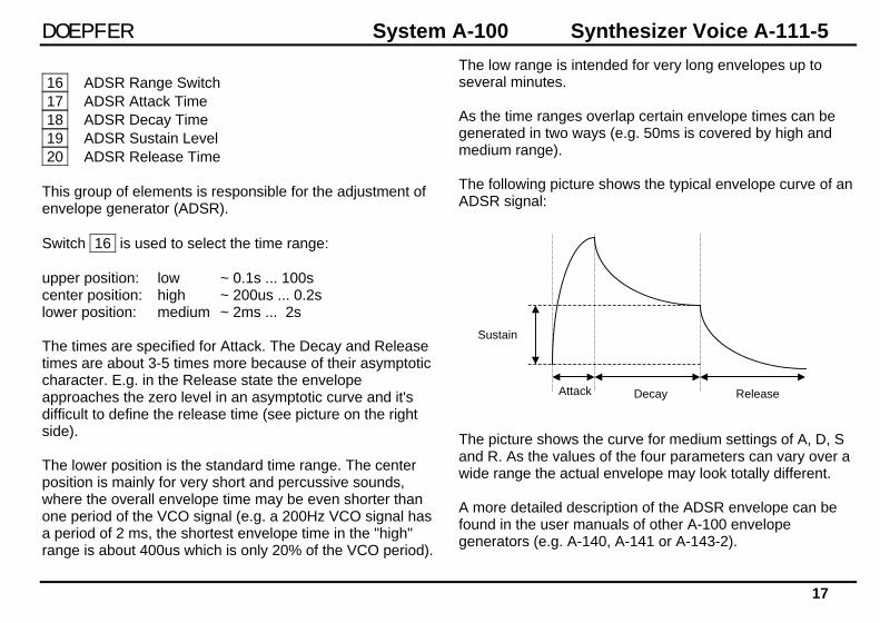
16 ADSR Range Switch 17 ADSR Attack Time 18 ADSR Decay Time 19 ADSR Sustain Level 20 ADSR Release Time This group of elements is responsible for the adjustment of envelope generator (ADSR). Switch 16 is used to select the time range: upper position: low ~ 0.1s ... 100s center position: high ~ 200us ... 0.2s lower position: medium ~ 2ms ... 2s The times are specified for Attack. The Decay and Release times are about 3-5 times more because of their asymptotic character. E.g. in the Release state the envelope approaches the zero level in an asymptotic curve and it's difficult to define the release time (see picture on the right side). The lower position is the standard time range. The center position is mainly for very short and percussive sounds, where the overall envelope time may be even shorter than one period of the VCO signal (e.g. a 200Hz VCO signal has a period of 2 ms, the shortest envelope time in the "high" range is about 400us which is only 20% of the VCO period).
The low range is intended for very long envelopes up to several minutes. As the time ranges overlap certain envelope times can be generated in two ways (e.g. 50ms is covered by high and medium range). The following picture shows the typical envelope curve of an ADSR signal: The picture shows the curve for medium settings of A, D, S and R. As the values of the four parameters can vary over a wide range the actual envelope may look totally different. A more detailed description of the ADSR envelope can be found in the user manuals of other A-100 envelope generators (e.g. A-140, A-141 or A-143-2).
Attack Decay Release
Sustain
Synthesizer Voice A-111-5 System A-100 DOEPFER
18
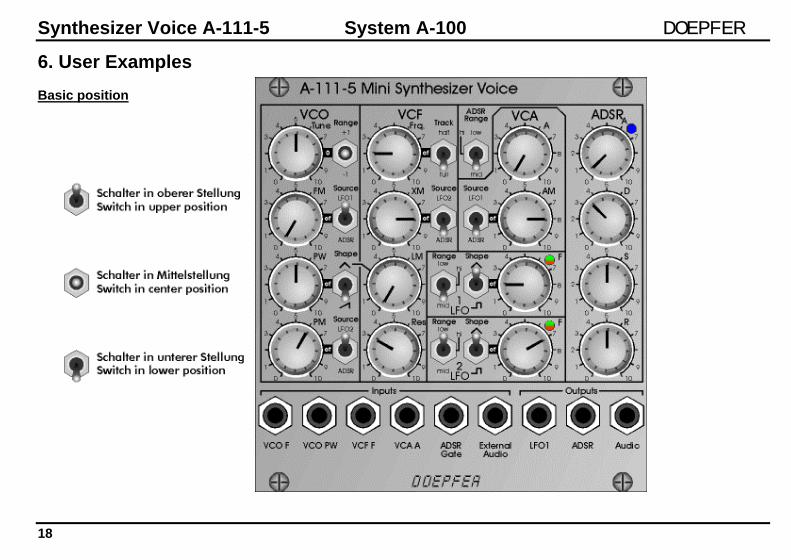
6. User Examples Basic position
DOEPFER System A-100 Synthesizer Voice A-111-5
19
The basic position of the controls shown on the previous page is a good starting point as it generates a well-known standard synthesizer sound. The VCO uses a combination of sawtooth and rectangle with a slow pulsewidth modulation to obtain a fatter sound. The frequency modulation of the VCO if off. The VCF has a light resonance and is modulated by the ADSR. The linear modulation of the VCF (LM) is off. The VCF tracking is on (i.e. the VCF frequency follows the VCO frequency). The VCA is also controlled by the ADSR and has no initial gain. LFO1 is not used in this patch, LFO2 is used to control the PWM of the VCO. The ADSR range switch is set to medium, the ADSR has a short Attack time, a moderate Decay time and medium settings for Sustain and Release. To obtain a sound both a CV and a Gate signal is required. CV and Gate can be supplied via the A-100 bus or the sockets at the front panel (please refer to the jumper settings in the appendix if you want to control the module from the A-100 bus).
Change the settings of the controls to find out how they affect the sound. You may e.g. some VCO frequency modulation by increasing the VCO FM control and play around with different frequencies and waveforms of LFO1. Please look at the DARK ENERGY user's manual for more examples. It is available on our website as a pdf file for download. DARK ENERGY is the stand-alone version of the module A-111-5 and has exactly the same sound generation unit.
Synthesizer Voice A-111-5 System A-100 DOEPFER
20
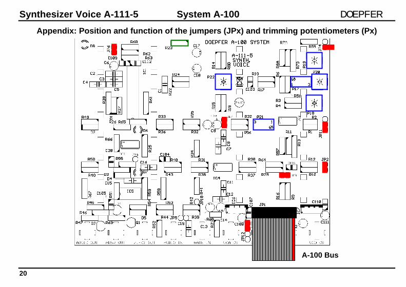
Appendix: Position and function of the jumpers (JPx) and trimming potentiometers (Px)
A-100 Bus
DOEPFER System A-100 Synthesizer Voice A-111-5
21
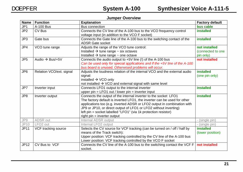
Jumper Overview Name Function Explanation Factory default JP1 A-100 Bus Bus connection bus cable JP2 CV Bus Connects the CV line of the A-100 bus to the VCO frequency control
voltage input (in addition to the VCO F socket) installed
JP3 Gate bus Connects the Gate line of the A-100 bus to the switching contact of the ADSR Gate socket
installed
JP4 VCO tune range Adjusts the range of the VCO tune control: Installed tune range ~ six octaves Installed tune range ~ one octave
not installed (connected to one pin only)
JP5 Audio Bus/+5V Connects the audio output to +5V line (!) of the A-100 bus Can be used only for special applications and if the +5V line of the A-100 bus board is unused. Otherwised problems will occur.
not installed
JP6 Relation VCO/ext. signal Adjusts the loudness relation of the internal VCO and the external audio signal: installed VCO only not installed VCO and external signal with same level
installed (one pin only)
JP7 Inverter input Connects LFO1 output to the internal inverter upper pin = LFO1 out / lower pin = inverter input
installed
JP8 Inverter output Connects the output of the internal inverter to the socket LFO1 The factory default is inverted LFO1, the inverter can be used for other applications too (e.g. inverted ADSR or LFO2 output in combination with JP9 or JP10, or direct output of LFO1 or LFO2 without inverting) left pin = socket labelled "LFO1" (via 1k protection resistor) right pin = inverter output
installed
JP9 ADSR out Internal ADSR output - (single pin) JP10 LFO2 out Internal LFO2 output - (single pin) JP11 VCF tracking source Selects the CV source for VCF tracking (can be turned on / off / half by
means of the Track switch): Upper position: VCF tracking controlled by the CV line of the A-100 bus Lower position: VCF tracking controlled by the VCO F socket
installed (lower position)
JP12 CV Bus to VCF Connects the CV line of the A-100 bus to the switching contact the VCF F socket.
not installed

Synthesizer Voice A-111-5 System A-100 DOEPFER
22
Trimming Potentiometers Overview
Name Function Explanation Factory default P17 VCO Scale adjusts the 1V/octave characteristics of the
socket "VCO F" or the bus CV adjusted to 1.00V/octave
P18 VCO Offset adjusts the VCO frequency offset 64 Hz @ center position of the VCO Tune control and Range switch in center position
P19 VCO Octave Switch + adjusts the upper position of the VCO range switch (+ 1 octave)
adjusted to +1 octave
P20 VCO Octave Switch - adjusts the lower position of the VCO range switch (- 1 octave)
adjusted to -1 octave
P21 VCF Scale adjusts the 1V/octave characteristics of the socket "VCF F" or bus CV (if the tracking switch is in the lower position "full")
adjusted to 1V/octave, VCF in self-oscillation (Resonance control fully CW)
P22 VCF Offset adjusts the VCF frequency offset ~ 10 Hz @ CCW position of the VCF Frq. control, VCF in self-oscillation (Resonance control fully CW, all VCF modulations off)
R23 Minimum VCA level adjusts the minimum VCA level (i.e. when VCA A control is fully CCW and all VCA modulations are off)
10k (a smaller value leads to a smaller minimum VCA level)
Remark: The specifications in this appendix are only for experienced users. Please do not change the settings of the jumpers or potentiometers if you do not have sufficient experience. Modules that have been misadjusted by the customer (jumpers and/or trimming potentiometers) are treated as repairs at the owner's expense ! The warranty is void if the module is modified or misadjusted by the customer (exception: changing the jumper settings is allowed without loosing the warranty).