Embed Size (px)
Citation preview
Dover Artificial Lift – Gas Lift
Equipment Catalog
INTRODUCTIONDover Artificial Lift – Gas Lift 4
Advantages of Gas Lift 5
Eight Facts about Gas Lift 5
TUBING RETRIEVABLE EQUIPMENTSR and JR Series Mandrels 6
LM and IM Series Mandrels 7
TP Series Gas Lift Valves 8
TC Series Check Valves 9
WIRELINE RETRIEVABLE EQUIPMENTD and F Series Oval Body Side Pocket Mandrels 11
R, H and U Series Round Body Side Pocket Mandrels 12
WP Series Gas Lift Valves 14
BK-2 and RK Latch Series 15
WD Series Dummy Valves 16
WO Series Orifice Valves 16
WF Series Gas Lift Valves 17
ADDITIONAL EQUIPMENT 18 • Arrowset Style Packers• Model R Packers• On/Off Tools• Stingers• Pump-Out Plugs• Ceramic Plugs• Nipples• Wireline Entry Guides
Table of Contents
2
3
DOVER ARTIFICIAL LIFT
Elevating the potential of artificial lift production.
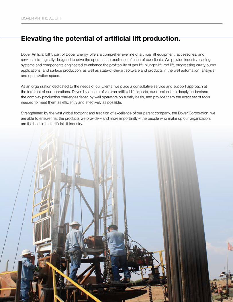
Dover Artificial Lift®, part of Dover Energy, offers a comprehensive line of artificial lift equipment, accessories, and services strategically designed to drive the operational excellence of each of our clients We provide industry-leading systems and components engineered to enhance the profitability of gas lift, plunger lift, rod lift, progressing cavity pump applications, and surface production, as well as state-of-the-art software and products in the well automation, analysis, and optimization space
As an organization dedicated to the needs of our clients, we place a consultative service and support approach at the forefront of our operations Driven by a team of veteran artificial lift experts, our mission is to deeply understand the complex production challenges faced by well operators on a daily basis, and provide them the exact set of tools needed to meet them as efficiently and effectively as possible
Strengthened by the vast global footprint and tradition of excellence of our parent company, the Dover Corporation, we are able to ensure that the products we provide – and more importantly – the people who make up our organization, are the best in the artificial lift industry
Dover Artificial Lift – Gas Lift
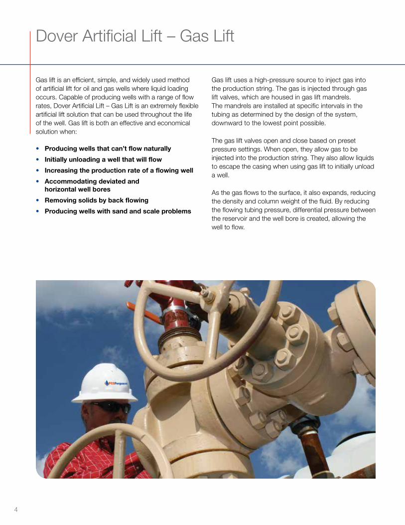
Gas lift is an efficient, simple, and widely used method of artificial lift for oil and gas wells where liquid loading occurs Capable of producing wells with a range of flow rates, Dover Artificial Lift – Gas Lift is an extremely flexible artificial lift solution that can be used throughout the life of the well Gas lift is both an effective and economical solution when:
• Producing wells that can’t flow naturally
• Initially unloading a well that will flow
• Increasing the production rate of a flowing well
• Accommodating deviated andhorizontal well bores
• Removing solids by back flowing
• Producing wells with sand and scale problems
Gas lift uses a high-pressure source to inject gas into the production string The gas is injected through gas lift valves, which are housed in gas lift mandrels The mandrels are installed at specific intervals in the tubing as determined by the design of the system, downward to the lowest point possible
The gas lift valves open and close based on preset pressure settings When open, they allow gas to be injected into the production string They also allow liquids to escape the casing when using gas lift to initially unload a well
As the gas flows to the surface, it also expands, reducing the density and column weight of the fluid By reducing the flowing tubing pressure, differential pressure between the reservoir and the well bore is created, allowing the well to flow
4
ADVANTAGES OF GAS LIFT VS OTHER ARTIFICIAL LIFT METHODS:
• Gas lift installations can generally handle the flowing conditions throughoutthe life of the well. Changing reservoir pressures, water cuts, and formationgas rates can be taken into account with the initial design.
• Gas lift equipment is durable and has few moving parts. A longer lifecan be expected compared to other means of artificial lift.
• Low initial installation cost.
• Low maintenance cost.
• Operator can control production rates from the surface.
• Produced sand has little effect on gas lift equipment.
• Gas lift is well suited for high deviations and horizontal well bores.
EIGHT FACTS ABOUT GAS LIFT:
Gas lift can produce almost any oil or gas well that requires artificial lift
Gas lift is limited only by the availability of gas
Gas lift can unload and kick-off wells that flow on their own
Gas lift can increase the rate of flowing wells
Gas lift can increase the velocity in a gas well to ensure produced fluids are recovered at the surface
Large tubing or annular flow gas lift can be utilized to produce extremely high rates
Intermittent gas lift can produce wells with low production rates or low reservoir pressure
Side pocket gas lift mandrels can be installed with dummy valves in the initial completion when the well may flow on its own Later, when the well has loading problems, gas lift valves can be installed with wireline to enable the gas lift system
Dover Artificial Lift – Gas Lift offers an extensive selection of gas lift equipment in various sizes and materials to ensure optimal production from your gas lift system
5
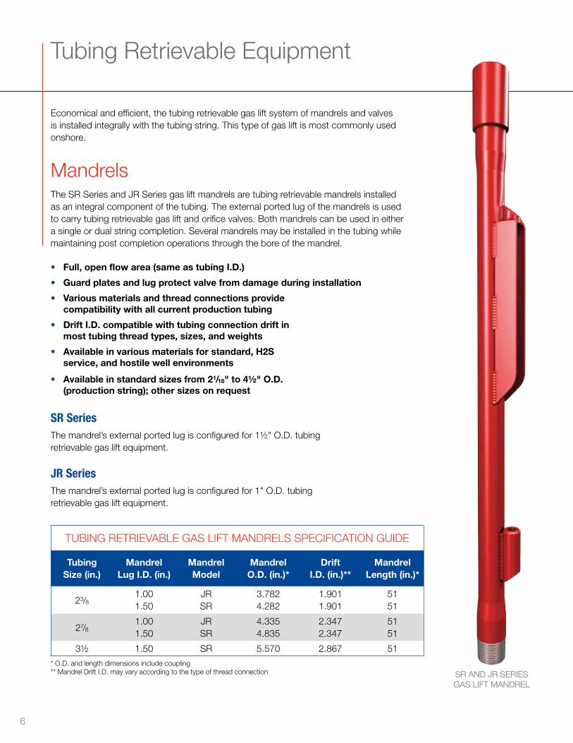
Tubing Retrievable Equipment
Economical and efficient, the tubing retrievable gas lift system of mandrels and valves is installed integrally with the tubing string This type of gas lift is most commonly used onshore
MandrelsThe SR Series and JR Series gas lift mandrels are tubing retrievable mandrels installed as an integral component of the tubing The external ported lug of the mandrels is used to carry tubing retrievable gas lift and orifice valves Both mandrels can be used in either a single or dual string completion Several mandrels may be installed in the tubing while maintaining post completion operations through the bore of the mandrel
• Full, open flow area (same as tubing I.D.)
• Guard plates and lug protect valve from damage during installation
• Various materials and thread connections providecompatibility with all current production tubing
• Drift I.D. compatible with tubing connection drift inmost tubing thread types, sizes, and weights
• Available in various materials for standard, H2Sservice, and hostile well environments
• Available in standard sizes from 21/16" to 4½" O.D.(production string); other sizes on request
SR SeriesThe mandrel’s external ported lug is configured for 1½" O D tubing retrievable gas lift equipment
JR SeriesThe mandrel’s external ported lug is configured for 1" O D tubing retrievable gas lift equipment
SR AND JR SERIES GAS LIFT MANDREL
* O D and length dimensions include coupling** Mandrel Drift I D may vary according to the type of thread connection
TUBING RETRIEVABLE GAS LIFT MANDRELS SPECIFICATION GUIDE
Tubing Size (in.)
Mandrel Lug I.D. (in.)
Mandrel Model
Mandrel O.D. (in.)*
Drift I.D. (in.)**
Mandrel Length (in.)*
23/81 001 50
JRSR
3 7824 282
1 9011 901
5151
27/81 001 50
JRSR
4 3354 835
2 3472 347
5151
3½ 1 50 SR 5 570 2 867 51
6
LM SERIESGAS LIFT MANDREL
IM SERIES GAS LIFTMANDREL
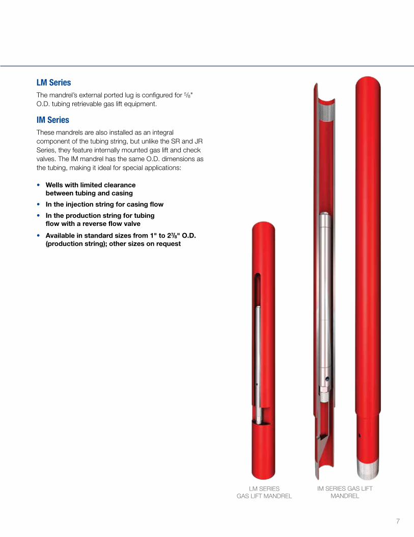
LM SeriesThe mandrel’s external ported lug is configured for 5/8" O D tubing retrievable gas lift equipment
IM SeriesThese mandrels are also installed as an integral component of the tubing string, but unlike the SR and JR Series, they feature internally mounted gas lift and check valves The IM mandrel has the same O D dimensions as the tubing, making it ideal for special applications:
• Wells with limited clearancebetween tubing and casing
• In the injection string for casing flow
• In the production string for tubingflow with a reverse flow valve
• Available in standard sizes from 1" to 27/8" O.D.(production string); other sizes on request
7
Tubing Retrievable Equipment cont
Gas Lift and Check Valves Dover Artificial Lift – Gas Lift offers a comprehensive line of valves for either injection pressure or production pressure operation Designed to anticipate changes in well characteristics and manufactured to the highest quality standards, our gas lift and check valves offer exceptional performance and reliability over the life of the well
TP SERIES GAS LIFT VALVESThe TP Series gas lift valves are tubing retrievable, injection pressure operated valves with a nitrogen charged dome and bellows configuration The valve’s dome charge pressure is calculated for proper valve operation at the designed depth and temperature of operation The dome pressure charge is preset prior to installation in the gas lift mandrel These normally closed valves are opened after the gas lift injection pressure overcomes the downward force of the dome charge pressure above the bellows
TP Series gas lift valves are designed for intermittent or continuous flow applications with tubing retrievable gas lift mandrels Smaller size valves are available for use with the IM and CT-IM special application mandrels for packoff, special clearance, and smaller diameter installations
• Large dome volume improves operating efficiency
• Port sizes from 1/8" to ½" for optimum gas passage
• Reverse flow check valve (TP-1 and TP-1.5 models)
• Mechanical travel stop increasesthe cycle life of the bellows
• Three-ply Monel® bellows extends life
• Silicon fluid bellows protection
• Replaceable floating Monel® seat(tungsten material available)
• Silver-brazed bellows connections
• Stainless steel or Monel® materials available
• Pressure rating up to 1800 psi Ptro maximum
• Temperature rating of 280º F (standard service)
• Available in 5/8", 1" or 1½" O.D.
TP Valve Series• The TP-625 model is a 5/8" O D valve
• The TP-1 model is a 1" O D valve
• The TP-1 5 model is a 1½" O D valve
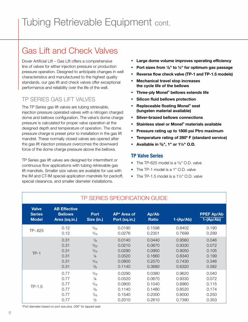
*Port diameter based on port size plus 006" for lapped seat
TP SERIES SPECIFICATION GUIDE
Valve Series Model
AB Effective Bellows
Area (sq.in.)Port
Size (in.)AP* Area of Port (sq.in.)
Ap/Ab Ratio 1-(Ap/Ab)
PPEF Ap/Ab 1-(Ap/Ab)
TP- 6250 120 12
5/32
3/16
0 01900 0276
0 15980 2301
0 84020 7699
0 1900 299
TP-1
0 310 310 310 310 310 31
1/85/32
3/16
1/45/16
3/8
0 01400 02100 02900 05200 08000 1140
0 04400 06700 09500 16600 25700 3680
0 95600 93300 90500 83400 74300 6320
0 0460 0720 1050 1990 3460 582
TP-1 5
0 770 770 770 770 770 77
3/16
1/45/16
3/87/16
½
0 02900 05200 08000 11400 15400 2010
0 03800 06700 10400 14800 20000 2610
0 96200 93300 89600 85200 80000 7390
0 0400 0720 1150 1740 2500 353
8
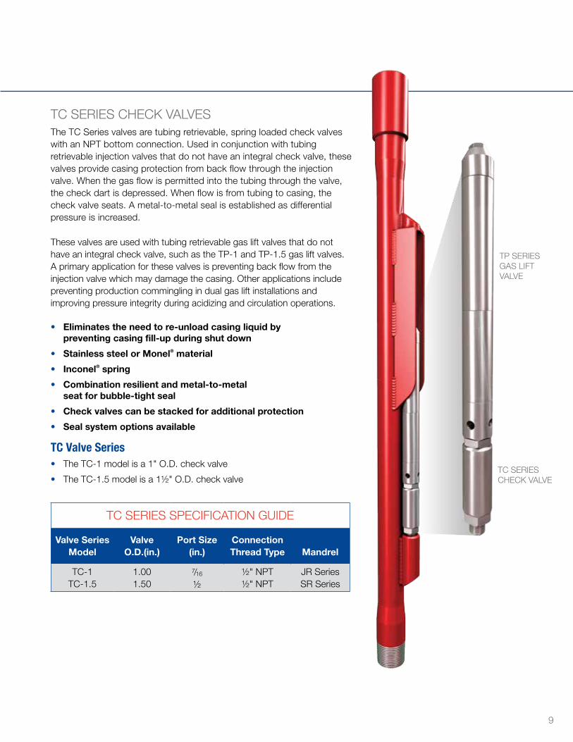
TC SERIES CHECK VALVESThe TC Series valves are tubing retrievable, spring loaded check valves with an NPT bottom connection Used in conjunction with tubing retrievable injection valves that do not have an integral check valve, these valves provide casing protection from back flow through the injection valve When the gas flow is permitted into the tubing through the valve, the check dart is depressed When flow is from tubing to casing, the check valve seats A metal-to-metal seal is established as differential pressure is increased
These valves are used with tubing retrievable gas lift valves that do not have an integral check valve, such as the TP-1 and TP-1 5 gas lift valves A primary application for these valves is preventing back flow from the injection valve which may damage the casing Other applications include preventing production commingling in dual gas lift installations and improving pressure integrity during acidizing and circulation operations
• Eliminates the need to re-unload casing liquid bypreventing casing fill-up during shut down
• Stainless steel or Monel® material
• Inconel® spring
• Combination resilient and metal-to-metalseat for bubble-tight seal
• Check valves can be stacked for additional protection
• Seal system options available
TC Valve Series• The TC-1 model is a 1" O D check valve
• The TC-1 5 model is a 1½" O D check valve
TP SERIES GAS LIFT VALVE
TC SERIES CHECK VALVE
TC SERIES SPECIFICATION GUIDE
Valve Series Model
Valve O.D.(in.)
Port Size (in.)
Connection Thread Type Mandrel
TC-1 TC-1 5
1 001 50
7/16
½½" NPT½" NPT
JR SeriesSR Series
9
Wireline Retrievable Equipment
The wireline retrievable gas lift system utilizes side pocket mandrels that are installed integrally in the tubing string, but the gas lift valves and latches can be retrieved and replaced with wireline to avoid costly workover operations
Side Pocket MandrelsPCS Ferguson offers a comprehensive line of side pocket mandrels for a variety of well completion applications Our engineering, manufacturing, and quality processes represent years of experience and dedication to providing top quality side pocket mandrels with enhanced features and specifications to meet the most demanding requirements
Our family of side pocket mandrels includes both oval and round body configurations The oval body mandrels, with either machined or forged pocket designs, are typically used in dual string completions The round body mandrels are full opening mandrels commonly
used in high pressure environments and special clearance applications
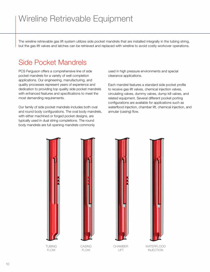
Each mandrel features a standard side pocket profile to receive gas lift valves, chemical injection valves, circulating valves, dummy valves, dump kill valves, and related equipment Several different pocket porting configurations are available for applications such as waterflood injection, chamber lift, chemical injection, and annular (casing) flow
TUBINGFLOW
CASINGFLOW
CHAMBERLIFT
WATERFLOODINJECTION
10
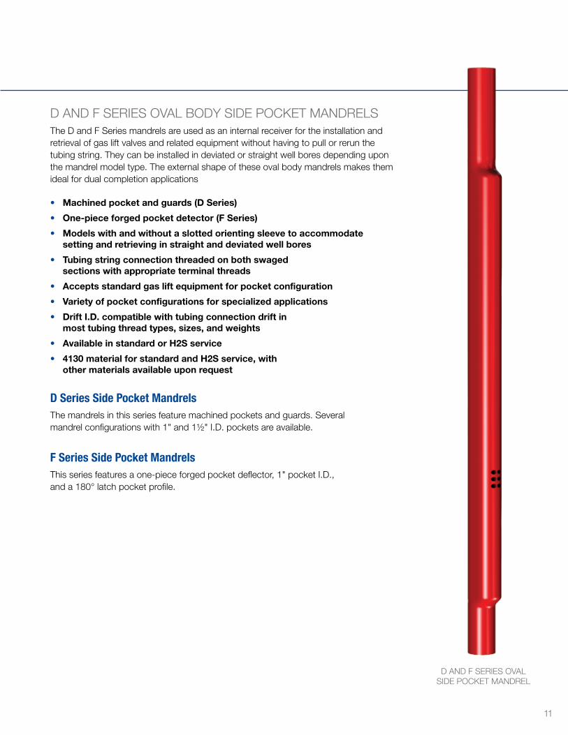
D AND F SERIES OVAL BODY SIDE POCKET MANDRELSThe D and F Series mandrels are used as an internal receiver for the installation and retrieval of gas lift valves and related equipment without having to pull or rerun the tubing string They can be installed in deviated or straight well bores depending upon the mandrel model type The external shape of these oval body mandrels makes them ideal for dual completion applications
• Machined pocket and guards (D Series)
• One-piece forged pocket detector (F Series)
• Models with and without a slotted orienting sleeve to accommodate setting and retrieving in straight and deviated well bores
• Tubing string connection threaded on both swaged sections with appropriate terminal threads
• Accepts standard gas lift equipment for pocket configuration
• Variety of pocket configurations for specialized applications
• Drift I.D. compatible with tubing connection drift in most tubing thread types, sizes, and weights
• Available in standard or H2S service
• 4130 material for standard and H2S service, with other materials available upon request
D Series Side Pocket MandrelsThe mandrels in this series feature machined pockets and guards Several mandrel configurations with 1" and 1½" I D pockets are available
F Series Side Pocket MandrelsThis series features a one-piece forged pocket deflector, 1" pocket I D , and a 180° latch pocket profile
D AND F SERIES OVALSIDE POCKET MANDREL
11
Wireline Retrievable Equipment cont
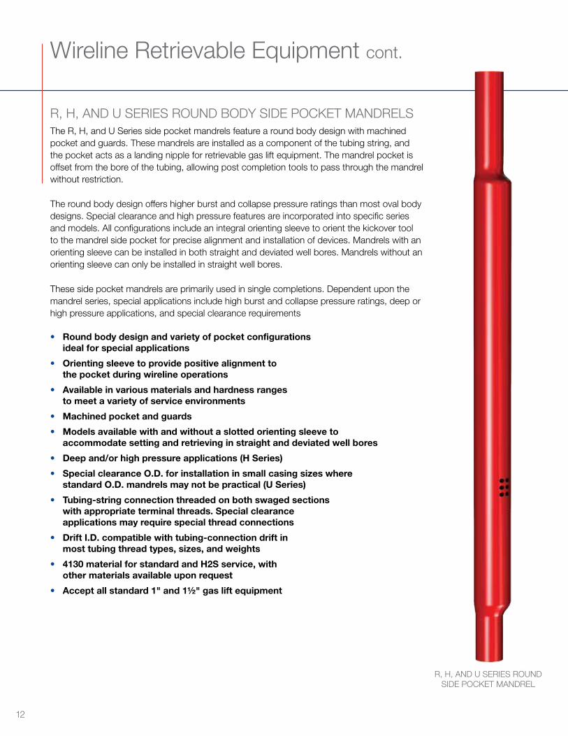
R, H, AND U SERIES ROUND BODY SIDE POCKET MANDRELSThe R, H, and U Series side pocket mandrels feature a round body design with machined pocket and guards These mandrels are installed as a component of the tubing string, and the pocket acts as a landing nipple for retrievable gas lift equipment The mandrel pocket is offset from the bore of the tubing, allowing post completion tools to pass through the mandrel without restriction
The round body design offers higher burst and collapse pressure ratings than most oval body designs Special clearance and high pressure features are incorporated into specific series and models All configurations include an integral orienting sleeve to orient the kickover tool to the mandrel side pocket for precise alignment and installation of devices Mandrels with an orienting sleeve can be installed in both straight and deviated well bores Mandrels without an orienting sleeve can only be installed in straight well bores
These side pocket mandrels are primarily used in single completions Dependent upon the mandrel series, special applications include high burst and collapse pressure ratings, deep or high pressure applications, and special clearance requirements
• Round body design and variety of pocket configurations ideal for special applications
• Orienting sleeve to provide positive alignment to the pocket during wireline operations
• Available in various materials and hardness ranges to meet a variety of service environments
• Machined pocket and guards
• Models available with and without a slotted orienting sleeve to accommodate setting and retrieving in straight and deviated well bores
• Deep and/or high pressure applications (H Series)
• Special clearance O.D. for installation in small casing sizes where standard O.D. mandrels may not be practical (U Series)
• Tubing-string connection threaded on both swaged sections with appropriate terminal threads. Special clearance applications may require special thread connections
• Drift I.D. compatible with tubing-connection drift in most tubing thread types, sizes, and weights
• 4130 material for standard and H2S service, with other materials available upon request
• Accept all standard 1" and 1½" gas lift equipment
R, H, AND U SERIES ROUND SIDE POCKET MANDREL
12
R Series Side Pocket MandrelsThese round body mandrels with 1" and 1½" I D pockets are available in several configurations
H Series Side Pocket MandrelsThese high pressure mandrels have a 1" pocket I D and feature an enhanced burst and collapse pressure rating design for compatibility with most heavyweight tubulars This series is primarily used for deep and/or high pressure applications
U Series Side Pocket MandrelsThese mandrels have a 1" pocket I D and feature a special clearance O D for installation in small casing sizes where standard O D mandrels may not be practical The 1H high pressure model features a 1" I D pocket and no orienting sleeve
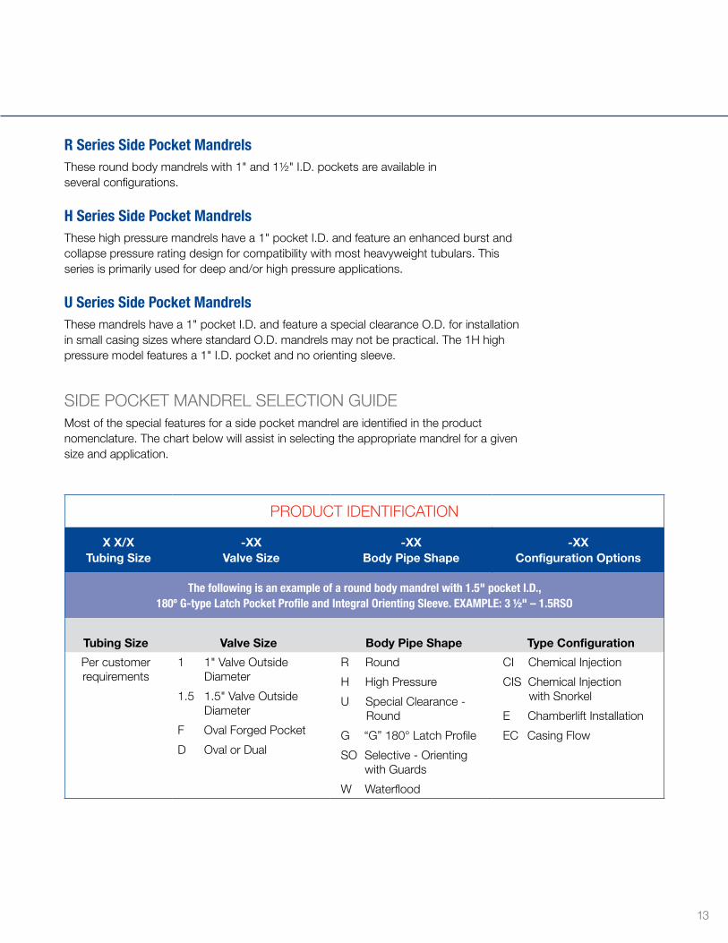
SIDE POCKET MANDREL SELECTION GUIDEMost of the special features for a side pocket mandrel are identified in the product nomenclature The chart below will assist in selecting the appropriate mandrel for a given size and application
PRODUCT IDENTIFICATION
X X/X Tubing Size
-XX Valve Size
-XX Body Pipe Shape
-XX Configuration Options
The following is an example of a round body mandrel with 1.5" pocket I.D., 180º G-type Latch Pocket Profile and Integral Orienting Sleeve. EXAMPLE: 3 1/2" – 1.5RSO
Tubing Size Valve Size Body Pipe Shape Type Configuration
Per customer requirements
1 1" Valve Outside Diameter
1 5 1 5" Valve Outside Diameter
F Oval Forged Pocket
D Oval or Dual
R Round
H High Pressure
U Special Clearance - Round
G “G” 180° Latch Profile
SO Selective - Orienting with Guards
W Waterflood
CI Chemical Injection
CIS Chemical Injection with Snorkel
E Chamberlift Installation
EC Casing Flow
13
Wireline Retrievable Equipment cont
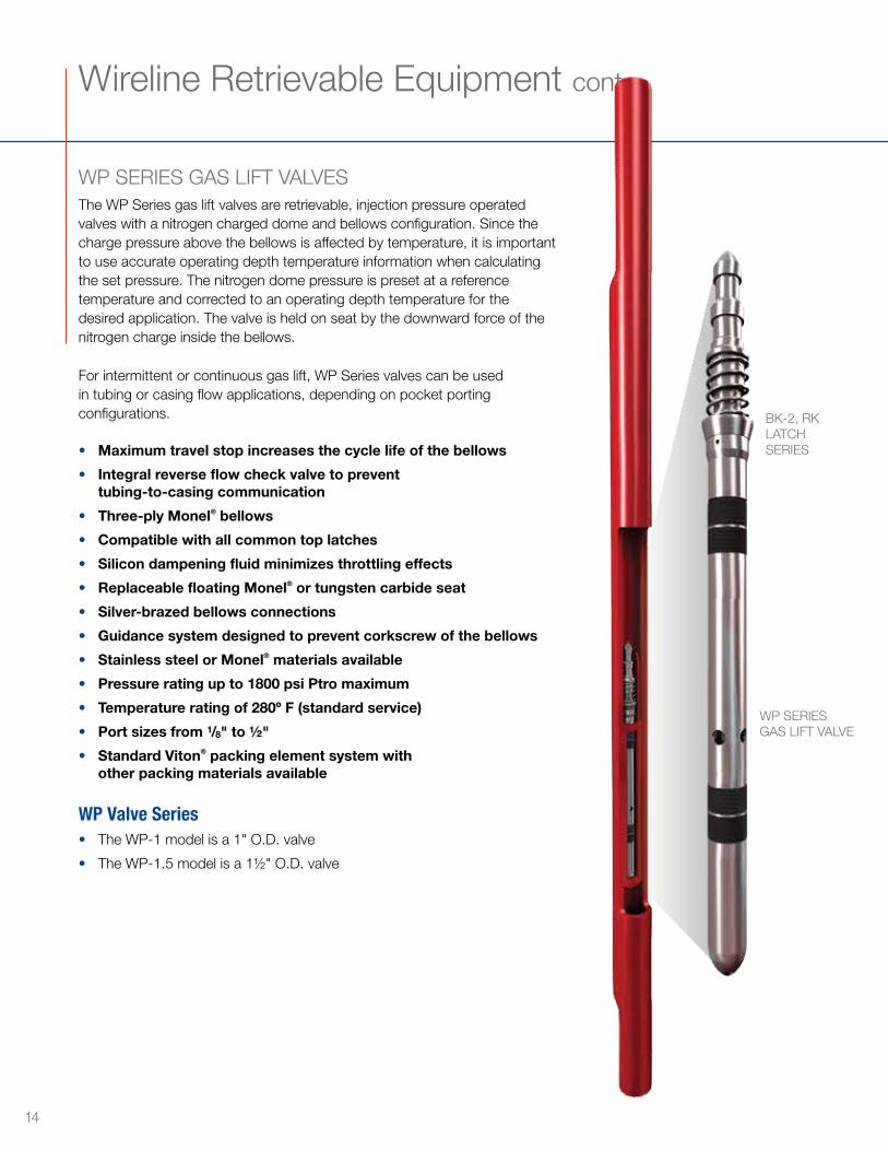
WP SERIES GAS LIFT VALVESThe WP Series gas lift valves are retrievable, injection pressure operated valves with a nitrogen charged dome and bellows configuration Since the charge pressure above the bellows is affected by temperature, it is important to use accurate operating depth temperature information when calculating the set pressure The nitrogen dome pressure is preset at a reference temperature and corrected to an operating depth temperature for the desired application The valve is held on seat by the downward force of the nitrogen charge inside the bellows
For intermittent or continuous gas lift, WP Series valves can be used in tubing or casing flow applications, depending on pocket porting configurations
• Maximum travel stop increases the cycle life of the bellows
• Integral reverse flow check valve to prevent tubing-to-casing communication
• Three-ply Monel® bellows
• Compatible with all common top latches
• Silicon dampening fluid minimizes throttling effects
• Replaceable floating Monel® or tungsten carbide seat
• Silver-brazed bellows connections
• Guidance system designed to prevent corkscrew of the bellows
• Stainless steel or Monel® materials available
• Pressure rating up to 1800 psi Ptro maximum
• Temperature rating of 280º F (standard service)
• Port sizes from 1/8" to ½"
• Standard Viton® packing element system with other packing materials available
WP Valve Series• The WP-1 model is a 1" O D valve
• The WP-1 5 model is a 1½" O D valve
BK-2, RK LATCH SERIES
WP SERIESGAS LIFT VALVE
14
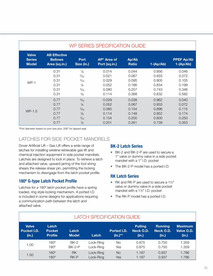
LATCHES FOR SIDE POCKET MANDRELSDover Artificial Lift – Gas Lift offers a wide range of latches for installing wireline retrievable gas lift and chemical injection equipment in side pocket mandrels Latches are designed to lock in place To retrieve a latch and attached valve, upward jarring of the tool string shears the release shear pin, permitting the locking mechanism to disengage from the latch pocket profile
180º G-type Latch Pocket ProfileLatches for a 180º latch pocket profile have a spring loaded, ring style locking mechanism A ported I D is included in some designs for applications requiring a communication path between the latch and attached valve
BK-2 Latch Series• BK-2 and BK-2-P are used to secure a
1" valve or dummy valve in a side pocket mandrel with a 1" I D pocket
• The BK-2-P model has a ported I D
RK Latch Series• RK and RK-P are used to secure a 1½"
valve or dummy valve in a side pocket mandrel with a 1½" I D pocket
• The RK-P model has a ported I D
*Port diameter based on port size plus 006" for lapped seat
LATCH SPECIFICATION GUIDE
Valve Pocket I.D.
(in.)
Latch Pocket Profile
Latch Model Latch
Ported I.D. (in.)**
Pulling Neck O.D.
(in.)
Running Neck O.D.
(in.)
Maximum Valve O.D.
(in.)
1 00180º180º
BK-2BK-2-P
Lock-RingLock-Ring
NoYes
0 8750 875
0 7500 750
1 3591 359
1 50180º180º
RKRK-P
Lock-RingLock-Ring
NoYes
1 1871 187
0 9370 937
1 7861 786
WP SERIES SPECIFICATION GUIDE
Valve Series Model
AB Effective Bellows
Area (sq.in.)Port
Size (in.)AP* Area of Port (sq.in.)
Ap/Ab Ratio 1-(Ap/Ab)
PPEF Ap/Ab 1-(Ap/Ab)
WP-1
0 310 310 310 310 310 31
1/85/32
3/16
1/45/16
3/8
0 0140 0210 0290 0520 0800 114
0 0440 0670 0950 1660 2570 368
0 9560 9330 9050 8340 7430 632
0 0460 0720 1050 1990 3460 582
WP-1 5
0 770 770 770 770 770 77
3/16
1/45/16
3/87/16
½
0 0290 0520 0800 1140 1540 201
0 0380 0670 1040 1480 2000 261
0 9620 9330 8960 8520 8000 739
0 0400 0720 1150 1740 2500 353
15
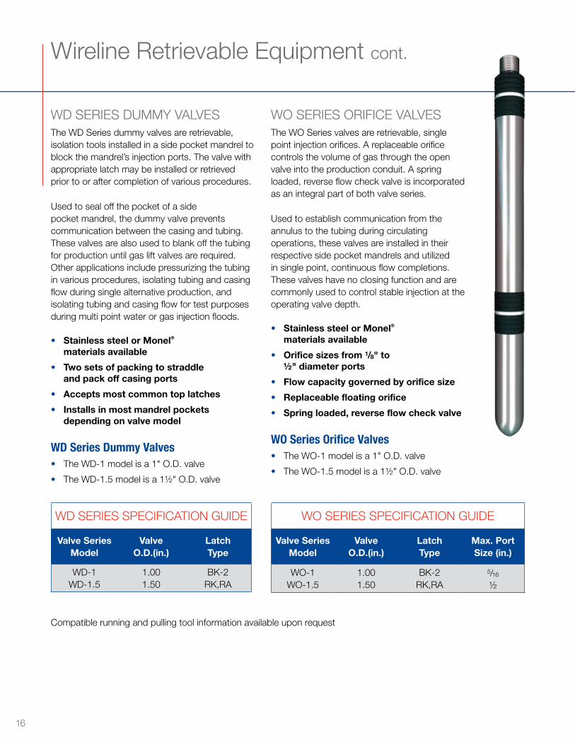
WD SERIES DUMMY VALVESThe WD Series dummy valves are retrievable, isolation tools installed in a side pocket mandrel to block the mandrel’s injection ports The valve with appropriate latch may be installed or retrieved prior to or after completion of various procedures
Used to seal off the pocket of a side pocket mandrel, the dummy valve prevents communication between the casing and tubing These valves are also used to blank off the tubing for production until gas lift valves are required Other applications include pressurizing the tubing in various procedures, isolating tubing and casing flow during single alternative production, and isolating tubing and casing flow for test purposes during multi point water or gas injection floods
• Stainless steel or Monel® materials available
• Two sets of packing to straddle and pack off casing ports
• Accepts most common top latches
• Installs in most mandrel pockets depending on valve model
WD Series Dummy Valves• The WD-1 model is a 1" O D valve
• The WD-1 5 model is a 1½" O D valve
Wireline Retrievable Equipment cont
Compatible running and pulling tool information available upon request
WO SERIES ORIFICE VALVESThe WO Series valves are retrievable, single point injection orifices A replaceable orifice controls the volume of gas through the open valve into the production conduit A spring loaded, reverse flow check valve is incorporated as an integral part of both valve series
Used to establish communication from the annulus to the tubing during circulating operations, these valves are installed in their respective side pocket mandrels and utilized in single point, continuous flow completions These valves have no closing function and are commonly used to control stable injection at the operating valve depth
• Stainless steel or Monel® materials available
• Orifice sizes from 1/8" to ½" diameter ports
• Flow capacity governed by orifice size
• Replaceable floating orifice
• Spring loaded, reverse flow check valve
WO Series Orifice Valves• The WO-1 model is a 1" O D valve
• The WO-1 5 model is a 1½" O D valve
WD SERIES SPECIFICATION GUIDE
Valve Series Model
Valve O.D.(in.)
Latch Type
WD-1 WD-1 5
1 001 50
BK-2RK,RA
WO SERIES SPECIFICATION GUIDE
Valve Series Model
Valve O.D.(in.)
Latch Type
Max. Port Size (in.)
WO-1 WO-1 5
1 001 50
BK-2RK,RA
5/16
½
16
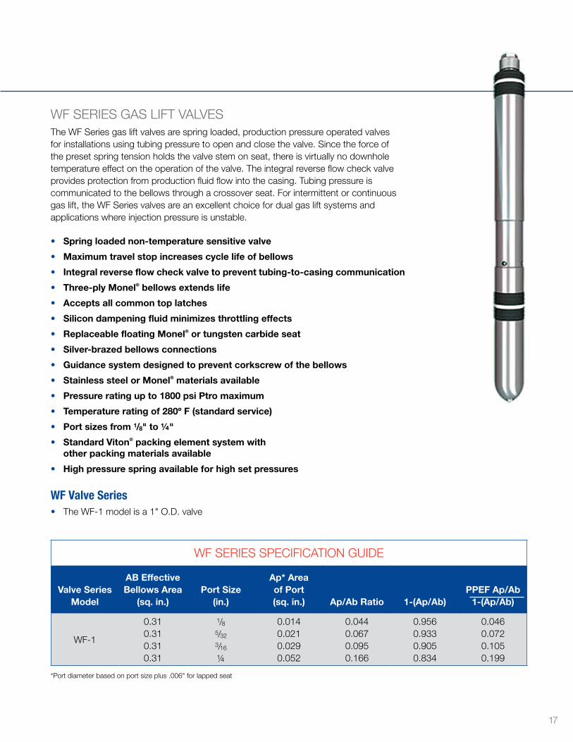
WF SERIES GAS LIFT VALVESThe WF Series gas lift valves are spring loaded, production pressure operated valves for installations using tubing pressure to open and close the valve Since the force of the preset spring tension holds the valve stem on seat, there is virtually no downhole temperature effect on the operation of the valve The integral reverse flow check valve provides protection from production fluid flow into the casing Tubing pressure is communicated to the bellows through a crossover seat For intermittent or continuous gas lift, the WF Series valves are an excellent choice for dual gas lift systems and applications where injection pressure is unstable
• Spring loaded non-temperature sensitive valve
• Maximum travel stop increases cycle life of bellows
• Integral reverse flow check valve to prevent tubing-to-casing communication
• Three-ply Monel® bellows extends life
• Accepts all common top latches
• Silicon dampening fluid minimizes throttling effects
• Replaceable floating Monel® or tungsten carbide seat
• Silver-brazed bellows connections
• Guidance system designed to prevent corkscrew of the bellows
• Stainless steel or Monel® materials available
• Pressure rating up to 1800 psi Ptro maximum
• Temperature rating of 280º F (standard service)
• Port sizes from 1/8" to 1/4"
• Standard Viton® packing element system with other packing materials available
• High pressure spring available for high set pressures
WF Valve Series• The WF-1 model is a 1" O D valve
WF SERIES SPECIFICATION GUIDE
Valve Series Model
AB Effective Bellows Area
(sq. in.)Port Size
(in.)
Ap* Area of Port (sq. in.) Ap/Ab Ratio 1-(Ap/Ab)
PPEF Ap/Ab 1-(Ap/Ab)
WF-1
0 310 310 310 31
1/85/32
3/16
1/4
0 0140 0210 0290 052
0 0440 0670 0950 166
0 9560 9330 9050 834
0 0460 0720 1050 199
*Port diameter based on port size plus 006" for lapped seat
17
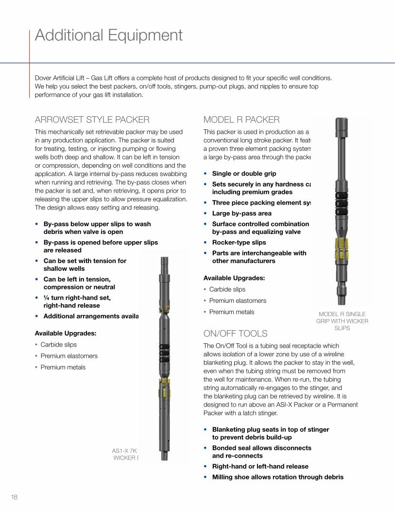
ARROWSET STYLE PACKERThis mechanically set retrievable packer may be used in any production application The packer is suited for treating, testing, or injecting pumping or flowing wells both deep and shallow It can be left in tension or compression, depending on well conditions and the application A large internal by-pass reduces swabbing when running and retrieving The by-pass closes when the packer is set and, when retrieving, it opens prior to releasing the upper slips to allow pressure equalization The design allows easy setting and releasing
• By-pass below upper slips to wash debris when valve is open
• By-pass is opened before upper slips are released
• Can be set with tension for shallow wells
• Can be left in tension, compression or neutral
• 1/4 turn right-hand set, right-hand release
• Additional arrangements available
Available Upgrades:
• Carbide slips
• Premium elastomers
• Premium metals
MODEL R PACKER This packer is used in production as a conventional long stroke packer It features a proven three element packing system and a large by-pass area through the packer
• Single or double grip
• Sets securely in any hardness casing, including premium grades
• Three piece packing element system
• Large by-pass area
• Surface controlled combination by-pass and equalizing valve
• Rocker-type slips
• Parts are interchangeable with other manufacturers
Available Upgrades:
• Carbide slips
• Premium elastomers
• Premium metals
ON/OFF TOOLSThe On/Off Tool is a tubing seal receptacle which allows isolation of a lower zone by use of a wireline blanketing plug It allows the packer to stay in the well, even when the tubing string must be removed from the well for maintenance When re-run, the tubing string automatically re-engages to the stinger, and the blanketing plug can be retrieved by wireline It is designed to run above an ASI-X Packer or a Permanent Packer with a latch stinger
• Blanketing plug seats in top of stinger to prevent debris build-up
• Bonded seal allows disconnects and re-connects
• Right-hand or left-hand release
• Milling shoe allows rotation through debris
Additional Equipment
Dover Artificial Lift – Gas Lift offers a complete host of products designed to fit your specific well conditions We help you select the best packers, on/off tools, stingers, pump-out plugs, and nipples to ensure top performance of your gas lift installation
MODEL R SINGLE GRIP WITH WICKER
SLIPS
AS1-X 7K WITH WICKER SLIPS
18
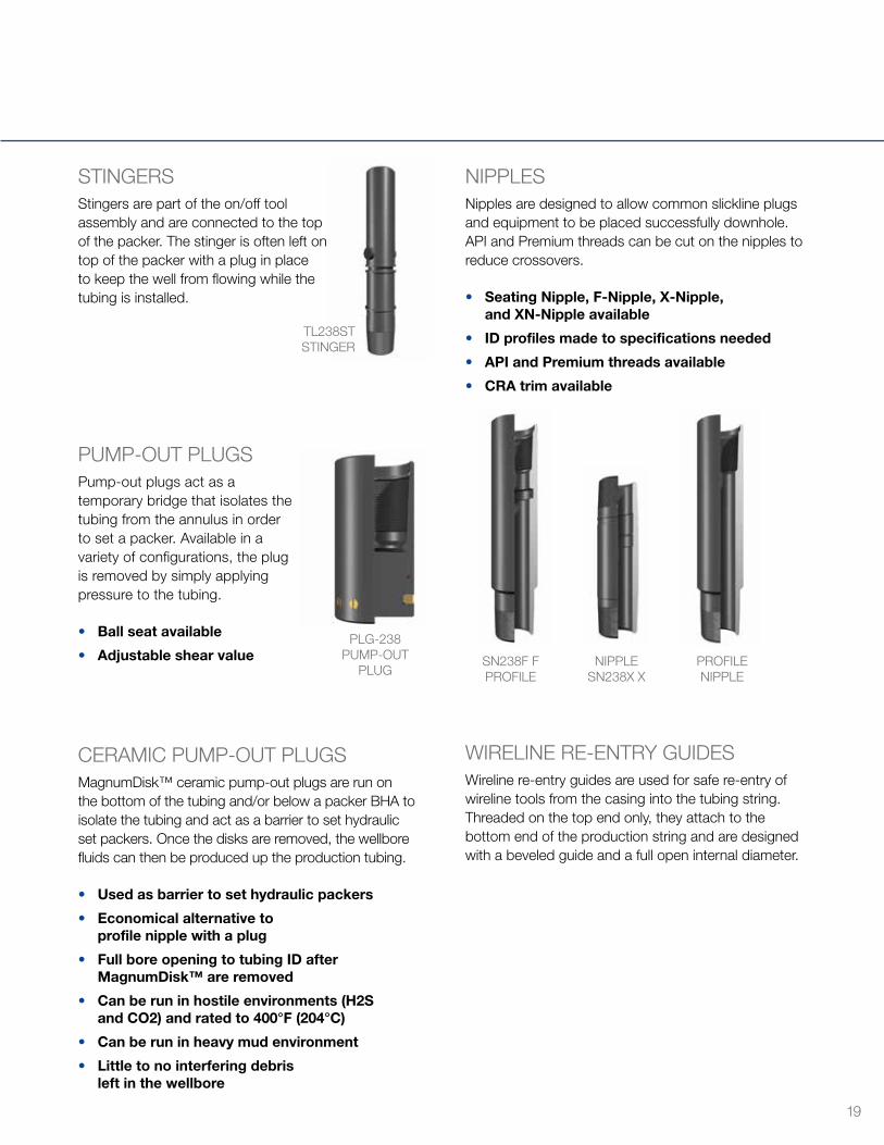
STINGERSStingers are part of the on/off tool assembly and are connected to the top of the packer The stinger is often left on top of the packer with a plug in place to keep the well from flowing while the tubing is installed
PUMP-OUT PLUGSPump-out plugs act as a temporary bridge that isolates the tubing from the annulus in order to set a packer Available in a variety of configurations, the plug is removed by simply applying pressure to the tubing
• Ball seat available
• Adjustable shear value
CERAMIC PUMP-OUT PLUGS MagnumDisk™ ceramic pump-out plugs are run on the bottom of the tubing and/or below a packer BHA to isolate the tubing and act as a barrier to set hydraulic set packers Once the disks are removed, the wellbore fluids can then be produced up the production tubing
• Used as barrier to set hydraulic packers
• Economical alternative to profile nipple with a plug
• Full bore opening to tubing ID after MagnumDisk™ are removed
• Can be run in hostile environments (H2S and CO2) and rated to 400°F (204°C)
• Can be run in heavy mud environment
• Little to no interfering debris left in the wellbore
NIPPLES Nipples are designed to allow common slickline plugs and equipment to be placed successfully downhole API and Premium threads can be cut on the nipples to reduce crossovers
• Seating Nipple, F-Nipple, X-Nipple, and XN-Nipple available
• ID profiles made to specifications needed
• API and Premium threads available
• CRA trim available
WIRELINE RE-ENTRY GUIDES Wireline re-entry guides are used for safe re-entry of wireline tools from the casing into the tubing string Threaded on the top end only, they attach to the bottom end of the production string and are designed with a beveled guide and a full open internal diameter
TL238ST STINGER
PLG-238 PUMP-OUT
PLUG SN238F F PROFILE
NIPPLE SN238X X
PROFILE NIPPLE
19
Partner with the best team in the business.
• Decades of experience recommending and servicing lift systems to accommodate changing well conditions
• Unrivaled expertise in plunger lift, gas lift, hydraulic lift, well control, and well unloading
• The best performing, highest quality, and safest products designed, engineered, and manufactured in-house
• Experienced and responsive field support staff with extensive local knowledge
• The highest commitment to the protection and safety of our employees, our customers, and the environment
• Comprehensive customer training and product support
Administrative & ManufacturingFrederick, CO 720 407 3550
AlabamaCitronelle 601 649 2551
CaliforniaBakersfield 661 322 7114
CanadaCalgary, AB 403 266 6139Edson, AB 780 723 2759Grand Prairie, AB 780 532 0804Red Deer, AB 403 340 3605
ArkansasConway 501 932 0449
ColoradoEvans 970 539 9003Denver 303 710 4191Parachute 970 285 9652
LouisianaHaynesville 318 464 8143
MississippiLaurel 601 649 2551
New MexicoFarmington 505 326 4239Hobbs 575 397 0040
North DakotaMohall 701 240 5952Watford City 318 540 7715Watford City (Hydraulic Lift) 701 842 2231
OklahomaBroussard 337 837 9367Oklahoma City 405 440 1015Oklahoma City (Hydraulic Lift) 405 603 7492Stigler 918 967 3236Woodward 580 256 1317
PennsylvaniaCoraopolis 724 227 3263
TexasBridgeport 940 683 3898Buffalo 903 322 9300Cleburne 817 641 9900Houston 832 691 6907Perryton 405 213 8114Pleasanton 380 299 9745Pleasanton (Hydraulic Lift) 432 582 2335Karnes City 830 583 9900Kilgore 903 984 7624Odessa 432 556 4141Odessa (Service & Sales) 432 582 2335Odessa (Manufacturing) 432 334 8580Sonora 325 387 6260Tomball 713 906 1980Tyler 903 533 8266
UtahRoosevelt 435 722 4520Vernal 435 789 2031
WyomingCheyenne 435 722 4520Rock Springs 307 362 6010
Dover Artificial Lift offers a comprehensive line of artificial lift equipment, accessories, and services strategically designed to drive the operational excellence of each of our customers
Dover Artificial Lift products and services are available in the following North American locations:
doverals com