Embed Size (px)
Citation preview

Meridian 1 and Succession Communication Server for Enterprise 1000
DPNSS1 Maintenance Guide
Document Number: 553-3921-500Document Release: Standard 6.00Date: January 2002
Year Publish FCC TM
Copyright ©1991–2002 Nortel NetworksAll Rights Reserved
Printed in Canada
Information is subject to change without notice. Nortel Networks reserves the right to make changes in design or components as progress in engineering and manufacturing may warrant. This equipment has been tested and found to comply with the limits for a Class A digital device pursuant to Part 15 of the FCC rules, and the radio interference regulations of Industry Canada. These limits are designed to provide reasonable protection against harmful interference when the equipment is operated in a commercial environment. This equipment generates, uses and can radiate radio frequency energy, and if not installed and used in accordance with the instruction manual, may cause harmful interference to radio communications. Operation of this equipment in a residential area is likely to cause harmful interference in which case the user will be required to correct the interference at their own expense.
SL-1, Meridian 1, and Succession are trademarks of Nortel Networks.


Page 3 of 36
4
Revision historyJanuary 2002
Standard 6.00. This document is up-issued to include content changes for Meridian 1 Release 25.40 and Succession Communication Server for Enterprise 1000 systems.
April 2000Standard 5.00. This is a global document and is up-issued for X11 Release 25.0x.
October 1997Issue 4.00 released as Standard for Generic X11 Release 23.0x.
December 1994Issue 3.00 released as Standard for Generic X11 Release 21B.
May 1994Standard version issued for X11 including supplementary feature Release 20, containing updates to hardware references.
July 1993Standard version issued for Group H (Phase 8B).
October 1992Standard version issued for Group G (Phase 7C).
DPNSS1 Maintenance Guide

Page 4 of 36 Revision History
553-3921-500 Standard 6.00 January 2002

Page 5 of 36
6
Contents
About this document . . . . . . . . . . . . . . . . . . . . . . . 7
IDA status check and start-up . . . . . . . . . . . . . . . . 9
Circuit card replacement . . . . . . . . . . . . . . . . . . . . 35
DPNSS1 Maintenance Guide

Page 6 of 36
553-3921-500 Standard 6.00 January 2002

Page 7 of 36
8
About this documentThis document applies to Meridian 1 Internet Enabled and Succession Communication Server for Enterprise (CSE) 1000 systems.
This document is a global document. Contact your system supplier or your Nortel Networks representative to verify that the hardware and software described is supported in your area.
The DPNSS1 Maintenance Guide is part of the suite of Nortel Networks technical publication (NTPs) designed specifically for DPNSS1 applications.
This guide defines the procedures required to maintain DPNSS1 links, and lists all relevant system error messages.
Who should use this documentThis document is intended for individuals who maintain DPNSS1 networks.
How this document is organizedThe DPNSS1 Maintenance Guide has been arranged in the following sections:
• IDA status check and start-up - describes the status check that is used to verify that an IDA link is working normally, and the procedures required to take the PRI and DCHI from a disabled to an operational state; lists and defines trunk maintenance commands and messages; lists and describes digital trunk maintenance (DTM) error messages, initialize (INI) error messages, link reset error messages, channel reset error messages, stop count error message, test messages reset errors, channel configuration error messages, and Clock Controller (DTC) error messages.
DPNSS1 Maintenance Guide

Page 8 of 36
Note: The Integrated Digital Access (IDA) feature provides the hardware and software platform on the Meridian 1 for the support of DPNSS1 signaling protocols. The maintenance facilities and procedures are defined at the IDA level.
• Circuit card replacement - refers readers to the DPNSS1: Installation Guide (553-3921-200), where the relevant information is found.
553-3921-500 Standard 6.00 January 2002

Page 9 of 36
34
IDA status check and start-upContents
This section contains information on the following topics:
IDA status check . . . . . . . . . . . . . . . . . . . . . . . . . . . . . . . . . . . . . . . . . . 10
IDA start-up . . . . . . . . . . . . . . . . . . . . . . . . . . . . . . . . . . . . . . . . . . . . . . 12
IDA trunk maintenance commands and messages . . . . . . . . . . . . . . . . . 13
Synchronization . . . . . . . . . . . . . . . . . . . . . . . . . . . . . . . . . . . . . . . . . . . 15
Clock controller maintenance commands . . . . . . . . . . . . . . . . . . . . . . . 16
Resident fault monitoring . . . . . . . . . . . . . . . . . . . . . . . . . . . . . . . . . . . . 18
Hardware supported alarm summary . . . . . . . . . . . . . . . . . . . . . . . . . . . 19
Setting alarm thresholds . . . . . . . . . . . . . . . . . . . . . . . . . . . . . . . . . . . . . 20
Diagnostic error messages . . . . . . . . . . . . . . . . . . . . . . . . . . . . . . . . . . . 21
Digital Trunk Maintenance (DTM) error messages (LD 75) . . . . . . . . . 21
Initialize (INI) error messages . . . . . . . . . . . . . . . . . . . . . . . . . . . . . . . . 29
Link reset error messages . . . . . . . . . . . . . . . . . . . . . . . . . . . . . . . . . . . . 29
Channel reset error messages . . . . . . . . . . . . . . . . . . . . . . . . . . . . . . . . . 30
Stop count error message . . . . . . . . . . . . . . . . . . . . . . . . . . . . . . . . . . . . 30
Test messages reset errors . . . . . . . . . . . . . . . . . . . . . . . . . . . . . . . . . . . 31
Channel configuration error messages . . . . . . . . . . . . . . . . . . . . . . . . . . 31
Clock Controller (DTC) error messages (LD 60) . . . . . . . . . . . . . . . . . 33
DPNSS1 Maintenance Guide

Page 10 of 36 IDA status check and start-up
IDA status checkThe status check outlined in Table 1 on page 10 is used to verify that an IDA link is working normally. It assumes the PRI and DCHI are properly installed (for example, correctly cabled) and operational. If the IDA status is not as shown in the steps below, complete the check and proceed to IDA fault clearing procedures.
Once all problems are cleared, go to IDA start-up.
Table 1IDA status check (Part 1 of 2)
Step Action Response
1 Check the status LEDs on PRI cards For normal operation, only the green ACT LED is lit.
2 Note whether any other LED is lit and continue with the status check
3 Check the LED on the DCHI faceplate. If the LED is lit, the D-channel is disabled.
4 Check the status of all DCHI ports using:
LD 75
STAT DDSL
The DCHI status should be ENBL ACTIVE (DCHI enabled, and all configured channels are normally enabled)
OOSACTLOCALRAIL BK
NT8D72
553-3921-500 Standard 6.00 January 2002

IDA status check and start-up Page 11 of 36
5 Check the status of PRIs using:
LD 75
STAT DDCS
STAT DDCS n
Sample response:
DDCS 003 ENBLDDCS 004 ENBL
32 UNEQ30 DSBL
6 Check to assure the following IDA cables are connected correctly:
• PRI to DCHI cable
• 2Mb/s transmission cable from NT8D72BA to DSX (the digital cross connect)
Table 1IDA status check (Part 2 of 2)
Step Action Response
DPNSS1 Maintenance Guide

Page 12 of 36 IDA status check and start-up
IDA start-upTable 2 on page 12 provides the steps required to take the PRI and DCHI from a disabled to an operational state.
Table 2DASS2 start-up (Part 1 of 2)
Step Action Response
1 Check the status of PRI cards The PRI shown is disabled
2 Enable PRI using:
LD 75
ENL DDCS l(loop) ENBL
3 Enable the DCHI:
LD 75
ENL DDSL n ENBL IDLE (DCHI enabled, but all channels are disabled)
OOSACTLOCALRAIL BK
NT8D72
553-3921-500 Standard 6.00 January 2002

IDA status check and start-up Page 13 of 36
IDA trunk maintenance commands and messagesIDA trunk maintenance is performed using LD 75. Table 3 on page 13 is a general list of commands and status messages available in LD 75. Table 4 on page 14, Table 5 on page 15, and Table 6 on page 15 describe the various IDA trunk maintenance messages in LD 75.
4 Enable the LAP protocols for each real and virtual channel configured on the DPNSS1 link:
LD 75
STRT n
Both ends of the link should be started within 5 minutes of each other.
ENBL STARTING (the configured LAP protocols for each real and virtual channel configured on the DPNSS1 link are being enabled)
ENBL ACTIVE(the configured LAP protocols for each real and virtual channel configured on the DPNSS1 link are enabled)
Table 3IDA trunk maintenance commands available in LD 75 (Part 1 of 2)
Command Description
ENL DDSL n Enable DCHI, port n
ENL DDCS l Enable PRI loop l
ENL DTRC l c Enable real channel (loop, channel)
DIS DDSL n Disable DCHI, port n
DIS DDCS l Disable PRI loop n
DISI DDCS l Disable all channels, loop l as they become idle. The message “OK DISABLING” is displayed and further commands may be entered. Message DTM055 is displayed when all channels are disabled.
Table 2DASS2 start-up (Part 2 of 2)
Step Action Response
DPNSS1 Maintenance Guide

Page 14 of 36 IDA status check and start-up
DIS DTRC l c Disable real digital channel (loop, channel}
STAT DDSL Give status of entire DCHI
STAT DDSL n Give status of DCHI port n
STAT DDCS Give status of all PRI loops
STAT DDCS l Give status of PRI loop l, and a count of the number of channels in each state
STAT DTRC l c Give status of real digital channel (loop, channel)
STRT n Start DCHI, port n. The message “OK STARTING” is displayed and further commands may be entered. Message DTM301 is displayed when the link is started successfully.
CDSP Clear the display
CMIN u Clear the minor alarm for customer u
Table 4IDA trunk maintenance messages available in LD 75 — DCHI
Message Description
DSBL NOT RESPONDING The D Channel Handler is disabled and does not respond to a read/write test. All channels are disabled.
DSBL RESPONDING The D Channel Handler is disabled. All channels are disabled.
ENBL IDLE The D Channel Handler is enabled, but all channels are disabled
ENBL STARTING The D Channel Handler is enabled, but all channels are being enabled
ENBL ACTIVE The D Channel Handler is enabled, and all channels are enabled
Table 3IDA trunk maintenance commands available in LD 75 (Part 2 of 2)
Command Description
553-3921-500 Standard 6.00 January 2002

IDA status check and start-up Page 15 of 36
SynchronizationSynchronization between switches must always be provided in the case of DPNSS1 trunks, and every digital network must be individually checked for clocking configurations.
QPC775 Clock Controller cards have to be fitted in Meridian 1 system Options 21/21E, 51/51C, and 61/61C, and machine types ST/STE and NT, when a DPNSS1 link is installed. On Meridian 1 system Options 71 and 81/81C, two Clock Controller cards are used for synchronization. On Option 81/81C systems, and on systems supporting EuroISDN applications, the QPC775E Clock Controller card is required.
Table 5IDA trunk maintenance messages available in LD 75 — PRI2 card
Message Description
DSBL NOT RESPONDING The Network Pack is disabled and does not respond to a read/write test.
DSBL RESPONDING The Network Pack is disabled.
ENBL The Network Pack is enabled
Table 6IDA trunk maintenance messages available in LD 75 — B-channels
Message Description
UNEQ Not configured
DSBL Disabled
ENBL IDLE Enabled and available for a call
ENBL BUSY In use for a call
ENBL MBSY Maintenance busy; that is, unusable
DSBL RST, ENBL IDLE RST, ENBL BUSY RST, ENBL MBSY RST
Being reset; that is, unusable
DPNSS1 Maintenance Guide

Page 16 of 36 IDA status check and start-up
In a stand-alone switch or one with only analogue networking, the Clock Controller is not normally fitted. On Meridian 1 system Options 51/51C and 61/61C, card slots are dedicated for the Clock Controller. On the Meridian 1 system Option 21/21E the Clock Controller must be placed in one of the first four network positions.
In a dual processor system, the synchronization link must be connected to both Clock Controllers to allow for change over. The Clock Controller(s) can be connected to two synchronization links, the second being programmed to provide the system clocking if the first choice fails.
If the Meridian 1 is to provide clocking over a link, then there are no additional configuration changes required on the Meridian 1 system. If the Meridian 1 is to be synchronized to a particular link, then the PRI must be physically connected to the Clock Controller of the Meridian 1.
Clock controller maintenance commandsClock Controller maintenance is performed using LD 60. Table 7 on page 16 provides a general list of commands and status messages available in LD 60.
Table 7Clock controller commands available in LD 60 (Part 1 of 2)
Command Description
DIS CC N Disable specified system clock controller
DSYL L Disables remote alarm processing for loop L
ENL CC N Enable specified system clock controller
ENYL L Enables remote alarm processing for loop L
553-3921-500 Standard 6.00 January 2002

IDA status check and start-up Page 17 of 36
EREF Enables automatic switching and recovery of primary and secondary reference clocks when loops associated with these clocks are automatically enabled
MREF Disables automatic switching and recovery of the primary and secondary reference clocks when loops associated with these clocks are automatically disabled or in local alarm
SSCK N Provides status of system clock N. Indicates the active controller as well as active primary or secondary reference-clock source or free run.
SWCK Switches the system clock from the active to the standby clock. The reference-clock source remains unchanged.
TRCK xxx Set clock-controller tracking. Where xxx represents one of the following mnemonics:
PCK track primary clock
SCK track secondary clock
FRUN free-run mode
Table 7Clock controller commands available in LD 60 (Part 2 of 2)
Command Description
DPNSS1 Maintenance Guide

Page 18 of 36 IDA status check and start-up
Resident fault monitoringThe software currently monitors the alarms associated with a DPNSS1 link. These alarms are described in Table 8 on page 18.
There are two criteria:
• An alarm is present for more than the “persistence time” defined for that alarm.
• An alarm occurs more times than the “reset count threshold” within the period defined by the “monitor time” for that alarm.
In either case, the link is stopped, and a minor alarm is raised. When all alarms are cleared, the link is restarted. Various diagnostic messages are issued for alarms — please refer to “Diagnostic error messages” on page 21.
To support BTNR 188, four alarms are mandatory:
• Bit errors of worse than 10-3
• Alarm Indication Signal
• Loss of Frame Alignment
• Loss of Signal
Table 8Alarms
Alarm Description
TBF Transmit Buffer Full
FAE Frame Alignment Error
HER High Error Rate
TSF Transmit Signaling Failure
AIS Alarm Indication Signal
LOI Loss of Input
DAI Distant Alarm Indication
553-3921-500 Standard 6.00 January 2002

IDA status check and start-up Page 19 of 36
Hardware supported alarm summaryThe following list provides a summary of all alarms supported by hardware.
• Loss of Frame Alignment
• Frame Bit Error
• Alarm Indication Signal
• Loss of Signal
• Remote Alarm Indication
• Bipolar Violation
• CRC - 4
• Los of Multiframe Align
• Slip Error
DPNSS1 Maintenance Guide
Page 20 of 36 IDA status check and start-up
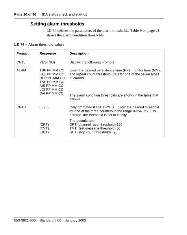
Setting alarm thresholdsLD 74 defines the parameters of the alarm thresholds. Table 9 on page 21 shows the alarm condition thresholds.
LD 74 – Alarm threshold values
Prompt Response Description
CNTL YES/(NO) Display the following prompts
ALRM TBF PP MM CCFAE PP MM CCHER PP MM CCTSF PP MM CCAIS PP MM CCLOI PP MM CCDAI PP MM CC
Enter the desired persistence time (PP), monitor time (MM), and repeat count threshold (CC) for one of the seven types of alarms
The alarm condition thresholds are shown in the table that follows.
CNTR 0- 255
(CRT)(TMT)(SCT)
Only prompted if CNTL=YES. Enter the desired threshold for one of the three counters in the range 0-254. If 255 is entered, the threshold is set to infinity.
The defaults are:CRT (channel reset threshold) 120TMT (test message threshold) 50SCT (stop count threshold) 20
553-3921-500 Standard 6.00 January 2002

IDA status check and start-up Page 21 of 36
Diagnostic error messagesThe following sections list the error messages which are issued for diagnostic alarms.
Digital Trunk Maintenance (DTM) error messages (LD 75)The DTM messages indicate problems with digital trunks detected by the Digital Trunk Maintenance program (LD 75)..
Table 9Alarm condition thresholds
Alarm Mnemonic PP MM CC
TBF 0-15 secs (5) 0-24 hrs (0) 0-15 (1)
FAE 0-15 secs (2) 0-24 hrs (1) 0-15 (4)
HER 0-15 mins (1) 0-24 hrs (1) 0-15 (10)
TSF 0-15 secs (0) 0-24 hrs (0) 0-15 (0)
AIS 0-15 mins (1) 0-24 hrs (1) 0-15 (4)
LOI 0-15 secs (0) 0-24 hrs (0) 0-15 (0)
DAI 1-15 mins (1) 0-24 hrs (1) 0-15 (5)
Table 10DTM error messages (Part 1 of 8)
DTM error code
Description Action to take
DTM000 Program Identifier
DTM001 Too many characters Check input and re-enter
DTM002 Invalid character input Check input and re-enter
DTM003 Invalid command Check input and re-enter
DTM004 Wrong number of parameters Check input and re-enter
DTM005 Invalid parameter Check input and re-enter
DPNSS1 Maintenance Guide

Page 22 of 36 IDA status check and start-up
DTM006 Invalid customer number Check input and re-enter
DTM020 Pack is not configured Check input and re-enter; If DTM020 is still output, check that the DTCS and DTSL are configured
DTM021 Pack number is not specified Check input and re-enter
DTM022 Pack number is out of range Check input and re-enter
DTM023 Pack is already enabled
DTM024 Pack does not respond Check that the pack switch is enabled and properly configured
DTM025 Loop is not a DTCS/DDCS Check input and re-enter; If DTM025 is still output, check the configuration record
DTM026 DTSL/DDSL is disabled
DTM027 Signaling link is not available Perform STAT on DTSL; if in service or enabled, then the far end of link is suspect
DTM030 Command is not allowed
DTM040 Message input failed Check that sufficient digital trunk I/O buffers are configured
DTM042 DTCS/DDCS cannot be disabled while its DTSL/DDSL is still enabled
DTSL must be disabled before DTCS is disabled
DTM043 Not a DTSL/DDSL Check input and re-enter
DTM047 DTCS/DDCS is disabled
DTM048 Channel is already disabled
Table 10DTM error messages (Part 2 of 8)
DTM error code Description Action to take
553-3921-500 Standard 6.00 January 2002

IDA status check and start-up Page 23 of 36
DTM049 A previous DISI has not beencompleted
Wait and re-enter DISI when current one has ended
DTM050 Message not defined by MSG Format the message using MSG com-mand first
DTM051 Invalid byte Check input and re-enter
DTM052 Invalid channel number Check input and re-enter
DTM053 Peripheral signaling card is disabled Enable peripheral signaling card and re-enter command
DTM054 Action not successful
DTM055 DISI complete
DTM300 n DTSL/DDSL n has been stopped and is in the ENBL IDLE state
DTM301 n DTSL/DDSL n has been started and is in the ENBL ACTIVE state
DTM302 n DTSL/DDSL n has been stopped and is in the ENBL ACTIVE state but has all the channels in the disabled state
Check the switch settings on the pack. If they are correct, check that the far end has started. If accompanied by a DTM334 message, then check the con-figuration at both ends of the link.
DTM303 n DTSL/DDSL n has failed to start and is still in the ENBL STARTING state but
Suspect faulty DCHI; may be accompanied by a major alarm
Table 10DTM error messages (Part 3 of 8)
DTM error code Description Action to take
DPNSS1 Maintenance Guide

Page 24 of 36 IDA status check and start-up
DTM304 n f DTSL/DDSL n has failed its memory test while being enabled and re-mains in the disabled state, with “f being one of the following reasons for failure:
0 — test not completed in time1 — ROM check failed2 — RAM check failed4 — HDLC test failed
Suspect faulty DCHI; may be accompanied by a major alarm
DTM305 n DTSL/DDSL n is undergoing memo-ry test, command ignored
Wait until the memory test has ended and then re-issue the command
DTM306 n DTSL/DDSL n being started, command ignored
Wait until the command has ended and the re-issue the command
DTM307 n DTSL/DDSL n being stopped, command ignored
Wait until the command has ended and the re-issue the command
DTM308 n Five minutes have elapsed since DTSL/DDSL n was started and placed in the active state, and no channel reset acknowledgments have beenreceived
Check that the far end has started
DTM309 n DTSL/DDSL n has failed to start; it will return to the idle state
Attempt a reset; If the fault persists, suspect a faulty DCHI; may be accompanied by a major alarm
DTM310 n z (see note)
Alarm z has been detected by DTSL/DDSL n and it has exceeded its persistence limit
Accompanied by a major alarm when <alarm> = 1-5; accompanied by a mi-nor alarm when <alarm> = 6
Table 10DTM error messages (Part 4 of 8)
DTM error code Description Action to take
553-3921-500 Standard 6.00 January 2002

IDA status check and start-up Page 25 of 36
DTM311 n z (see note)
Alarm z has been detected by DTSL/DDSL n but has not exceed-ed its persistence limit
Accompanied by a major alarm
DTM312 n z (see note)
Alarm repeat count threshold has been exceeded for alarm z on DTSL/DDSL n
Accompanied by a major alarm
DTM313 n Stop count threshold has been exceeded for DTSL/DDSL n
May be accompanied by a major alarm
DTM314 n DTSL/DDSL n has been disabled
DTM315 n DTSL/DDSL n has failed to respond to numerous “stop” messages and therefore will be disabled instead
Attempt a reset; If the fault persists, suspect a faulty DCHI; accompanied by a major alarm
DTM316 n z (see note)
Alarm z has been detected by DTSL/DDSL n; DTSL/DDSL n is not in the active state
DTM317 n DTSL/DDSL n does not respond Check switch settings on DCHI pack
DTM318 n DTSL/DDSL n has been enabled
DTM319 n DTSL/DDSL n is about to be started
DTM320 n c Real channel c on DTSL/DDSL n has failed to reset and remains in the disabled state
If multiple DTM320 messages occur, then suspect one of the following:
• link fault (check if an alarm is present)
• faulty DCHI
• far end signaling pack faulty
DTM322 n c Real channel c on DTSL/DDSL n has been reset
Table 10DTM error messages (Part 5 of 8)
DTM error code Description Action to take
DPNSS1 Maintenance Guide

Page 26 of 36 IDA status check and start-up
DTM324 n Channel reset threshold exceeded for DTSL/DDSL n
Suspect one of the following
• link fault (check if an alarm is present)
• faulty DCHI
• far end signaling pack faulty
DTM325 n DTSL/DDSL n is being reset
DTM326 n DTSL/DDSL n has been reset
DTM329 n c Channel is not in a state where it can be reset
DTM330 n Invalid command for the state that DTSL/DDSL n is in
Check the DTSL status and re-enter
DTM331 n Test message threshold has been exceeded for DTSL/DDSL n
If fault persists, suspect a faulty DCHI
DTM332 n A level 3 to level 2 signaling test has failed for DTSL/DDSL n
Link will be reset if this error persists
DTM335 n mi
DTSL/DDSL n has failed to a mes-sage sent to it; mi is the message in-dicator code for the message
If issued after a command has been entered, then repeat the command; If error continues, suspect a faulty DCHI
DTM336 n mi
An attempt to send a message to DTSL/DDSL n has failed; mi is the message indicator code for the message.
Note: A spurious DTM335 is likely to follow
DTM337 n li mi
Invalid input from DTSL/DDSL n; l is the length indicator, mi is the mes-sage indicator code for the message
Table 10DTM error messages (Part 6 of 8)
DTM error code Description Action to take
553-3921-500 Standard 6.00 January 2002

IDA status check and start-up Page 27 of 36
DTM338 n DTSL/DDSL n cannot be disabled because the DTCS/DDCS is dis-abled
DTCS(s) must be enabled first
DTM339 n x Five minutes have elapsed since DTSL/DDSL n was started and placed in the active state; some channel reset acknowledgments have bee received, but “x” channels fail to start
DTM340 n Although DTSL/DDSL n is active according to level 3, a report has been received from level 2 indicat-ing the link is idle
If fault persists, suspect a faulty DCHI
DTM341 n Although DTSL/DDSL n is idle according to level 3, a report has been received from level 2 indicat-ing the link is starting or active
If fault persists, suspect a faulty DCHI
DTM342 n c p
Level 2 has detected a discrepancy in the configuration of real channel c on DTSL/DDSL n when a message was sent from level 3; “p” indicates one of the following problems:
0 — channel number out of range1 — channel not configured4 — channel not active5 — li is incorrect6 — already configured7 — mi is out of range
Check the state and configuration of the channel
Table 10DTM error messages (Part 7 of 8)
DTM error code Description Action to take
DPNSS1 Maintenance Guide

Page 28 of 36 IDA status check and start-up
DTM344 n c p
Level 2 has detected a discrepancy in the configuration of real channel c on DTSL/DDSL n when a message was sent from level 3; “p” indicates one of the following problems:
0 — channel number out of range1 — channel not configured2 — type (DPNSS1) is wrong3 — side (A/B) is wrong4 — channel is not active
Check the channel configuration at the far end.
Note: A DTM344 with a “p” = 3 is only printed once after the STRT command is assigned, when the side of a DTSL is wrongly configured; DTM334 messages with other values for “p” printed every time that a discrepancy is found
DTM346 n c p
Level 3 has detected a discrepancy in the configuration of real channel c on DTSL/DDSL n when a message was sent from level 2; “p” indicates one of the following problems:
2 — type (DPNSS1) is wrong3 — side (A/B) is wrong
Level 3 will attempt to update level 2
DTM348 n All alarms cleared on DTSL/DDSL n
DTM350 Must switch reference clock before disabling
Note: for DTM310, DTM311, DTM312, and DTM316 the alarm “z” is one of the following code numbers:
0 — TBF (Transmit Buffer Full)1 — FAE (Frame Alignment Error)2 — HER (High Error Rate)3 — TSF (Transmit Signal Failure)4 — AIS (Alarm Indicator Signal)5 — LOI (Loss of Input)6 — DAI (Distant Alarm Indication)
Table 10DTM error messages (Part 8 of 8)
DTM error code Description Action to take
553-3921-500 Standard 6.00 January 2002
IDA status check and start-up Page 29 of 36
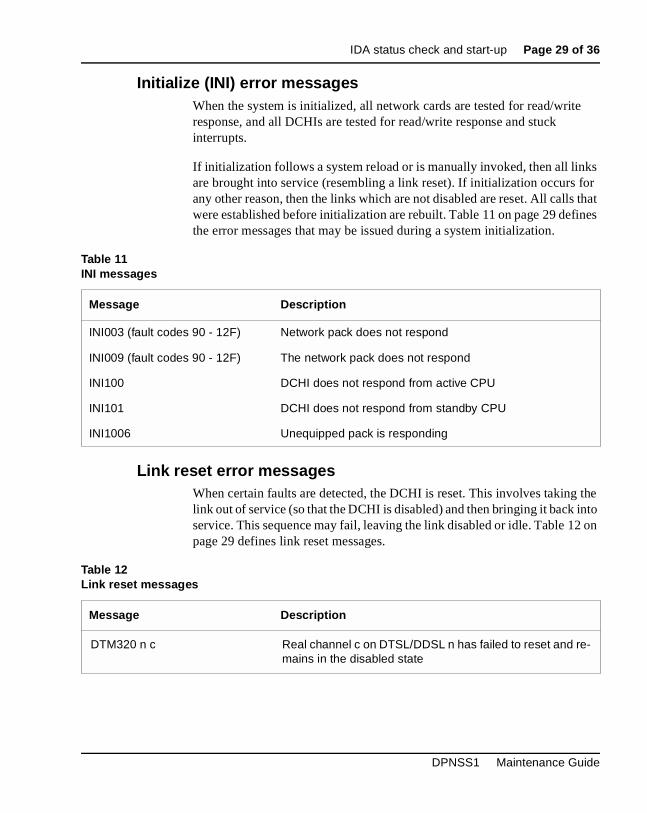
Initialize (INI) error messagesWhen the system is initialized, all network cards are tested for read/write response, and all DCHIs are tested for read/write response and stuck interrupts.
If initialization follows a system reload or is manually invoked, then all links are brought into service (resembling a link reset). If initialization occurs for any other reason, then the links which are not disabled are reset. All calls that were established before initialization are rebuilt. Table 11 on page 29 defines the error messages that may be issued during a system initialization.
Link reset error messagesWhen certain faults are detected, the DCHI is reset. This involves taking the link out of service (so that the DCHI is disabled) and then bringing it back into service. This sequence may fail, leaving the link disabled or idle. Table 12 on page 29 defines link reset messages.
Table 11INI messages
Message Description
INI003 (fault codes 90 - 12F) Network pack does not respond
INI009 (fault codes 90 - 12F) The network pack does not respond
INI100 DCHI does not respond from active CPU
INI101 DCHI does not respond from standby CPU
INI1006 Unequipped pack is responding
Table 12Link reset messages
Message Description
DTM320 n c Real channel c on DTSL/DDSL n has failed to reset and re-mains in the disabled state
DPNSS1 Maintenance Guide

Page 30 of 36 IDA status check and start-up
Channel reset error messagesA channel may be reset if clearing a call is difficult each time that a channel is enabled and if the channel buffer on the DCHI card overflows. If a channel is disabled, any call in progress is force-disconnected, and the DCHI is instructed to reset the associated Link Access Protocol. The channel is enabled when the reset is completed.
A channel reset may also be initiated by the DCHI, if there is difficulty in communicating with the far end.
If the number of channel resets since midnight exceeds the value defined as the “channel reset threshold” (CRT) defined in LD 74, then the link is reset and a minor alarm is raised. CRT may be set to infinity, in which case the link will not be reset due to channel reset failure.
Table 13 on page 30 defines the error messages which may be generated for a channel reset.
Stop count error messageA count is kept of the number of times since midnight that a link is stopped due to an alarm or link reset. If this count exceeds the “stop count threshold” (SCT) defined in LD 74, then the link is disabled. It remains disabled until it is manually brought back to service. SCT may be set to infinity, in which case the link will not be reset due to excessive stopping.
Table 13Channel reset error messages
Message Description
DTM325 n DTSL/DDSL n is being reset
DTM326 n DTSL/DDSL n has been reset
553-3921-500 Standard 6.00 January 2002

IDA status check and start-up Page 31 of 36
Table 14 on page 31 defines the error messages which may be generated for a stop count reset.
Test messages reset errorsTest messages are sent to all DCHIs every 30 seconds in order to check the level 3/level 2 interface. The test patterns should be echoed back unchanged. If the number of failed tests since midnight exceeds the “test message threshold” (TMT) defined in LD 74, then the link is reset and a minor alarm is raised. TMT may be set to infinity, in which case the link will not be reset due to test failure.
A check is also performed every 30 seconds on the DCHI states as read by the hardware and software. If there is a difference in the reading, then the link is reset and a minor alarm raised.
Table 15 on page 31 defines the error messages which may be generated for test messages reset:
Channel configuration error messages Each time that a DCHI is enabled, it is informed of the configuration of its Link Access Protocols. If a discrepancy between the hardware and software is detected during call processing, the software attempts to correct configuration. Diagnostic messages are generated for these faults.
Table 14Stop count message
Message Description
DTM313 n Stop count threshold has been exceeded for DTSL/DDSL n
Table 15Test messages reset errors
Message Description
DTM331 n Test message threshold has been exceeded for DTSL/DDSL n
DTM332 n A level 3 to level 2 signaling test has failed for DTSL/DDSL n
DPNSS1 Maintenance Guide

Page 32 of 36 IDA status check and start-up
If the software cannot send a message to the DCHI because no output buffer is available, a diagnostic message is generated. If the DCHI cannot send a message to the software because an input buffer is not available, no immediate message is sent. Both conditions are recorded in traffic printouts.
Input messages received by the software are verified that the length is consistent with the message type. A diagnostic message is generated for any discrepancy. Table 16 on page 32 defines channel configuration error messages.
Table 16Channel configuration error messages
Message Description
DTM342 n c p Level 2 has detected a discrepancy in the configuration of real channel c on DTSL/DDSL n when a message was sent from level 3; “p” indicates one of the following problems:0 — channel number out of range1 — channel not configured4 — channel not active5 — li is incorrect6 — already configured7 — mi is out of range
DTM344 n c p Level 2 has detected a discrepancy in the configuration of real channel c on DTSL/DDSL n when a message was sent from level 3; “p” indicates one of the following problems:0 — channel number out of range1 — channel not configured2 — type (DPNSS1) is wrong3 — side (A/B) is wrong4 — channel is not active
DTM346 n c p Level 3 has detected a discrepancy in the configuration of real channel c on DTSL/DDSL n when a message was sent from level 2; “p” indicates one of the following problems:2 — type (DPNSS1) is wrong3 — side (A/B) is wrong
553-3921-500 Standard 6.00 January 2002

IDA status check and start-up Page 33 of 36
Clock Controller (DTC) error messages (LD 60)The Digital Trunk Clock Controller (DTC) error messages in LD 60 indicate problems with the Clock Controllers. They are listed in Table 17 on page 33.
Table 17Clock controller status and error messages
Command Description
DTC001 Clock controller tracking on primary source loop.
DTC002 Clock controller tracking on secondary source loop.
DTC003 Clock controller cannot be accessed.
DTC004 Clock controller indicates clock-aging error.
DTC005 Reference clock switched to secondary source from primary.
DTC006 Reference clock switched to free-run mode from secondary or primary.
DTC007 Active reference clock is set to re-track primary.
DTC008 Active reference is free run or the clock controller cannot be accessed.
DTC009 Clock controller has been switched.
DTC010 Universal asynchronous receiver/transmitter (UART) error is detected.
DTC011 Clock control self-test failed; error exists.
DTC012 Clock control has reference-clock problem.
DTC013 Clock control has tracking problem.
DTC014 Clock control set to free run.
DTC015 Clock control set to secondary.
DTC016 Clock controller restored from free run or secondary to tracking on primary.
DTC017 Clock controller restored from free run to tracking on secondary.
DTC018 Cannot switch or restore to a reference clock because automatic reference-clock switching option is disabled.
DPNSS1 Maintenance Guide
Page 34 of 36 IDA status check and start-up
553-3921-500 Standard 6.00 January 2002

Page 35 of 36
36
Circuit card replacement
For detailed information on how to replace the 2Mb/s NT8D72 PRI card, the NTCK43 DPRI card, the NT5K35, the NT5K75 or the NT6D11AE DCHI card, and the QPC775 or NTRB53 Clock Controller, please refer to the DPNSS1: Installation Guide (553-3921-200).
DPNSS1 Maintenance Guide

Page 36 of 36 Circuit card replacement
553-3921-500 Standard 6.00 January 2002


Family Product Manual Contacts Copyright FCC notice Trademarks Document number Product release Document release Date Publish
Meridian 1 and Succession Communication Server for Enterprise 1000
DPNSS1Maintenance Guide
Copyright ©1991–2002 Nortel NetworksAll Rights ReservedInformation is subject to change without notice. Nortel Networks reserves the right to make changes in design or components as progress in engineering and manufacturing may warrant. This equipment has been tested and found to comply with the limits for a Class A digital device pursuant to Part 15 of the FCC rules, and the radio interference regulations of Industry Canada. These limits are designed to provide reasonable protection against harmful interference when the equipment is operated in a commercial environment. This equipment generates, uses and can radiate radio frequency energy, and if not installed and used in accordance with the instruction manual, may cause harmful interference to radio communications. Operation of this equipment in a residential area is likely to cause harmful interference in which case the user will be required to correct the interference at their own expense.SL-1, Meridian 1, and Succession are trademarks of Nortel Networks.
Publication number: 553-3921-500Document release: Standard 6.00Date: January 2002Printed in Canada
TM