Embed Size (px)
Citation preview

Received his B.S., M.S. and Ph.D. degrees in Department of Electrical Engineering, from HUST, in 1984, 1987 and 1991, respectively.
Visiting scholar in University of Calgary, Canada, from Jan. 1989 to Jan. 1990, and in Queen’s University of Belfast from Dec. 1994 to Dec. 1995 respectively. He was doing researches in Technical University of Berlin from Apr. 1996 to Apr. 1997 under the support of Humboldt Foundation.
Research fields: power system operation and control, the excitation control of synchronous generator and applications of high power electronic technology to power systems.
Dr. Chengxiong Mao,ProfessorSchool of Electrical and Electronic EngineeringHuazhong University of Science and Technology (HUST)P. R. China
1

Multi-level DC Distribution System and Key Technologies
Chengxiong Mao
[email protected] of Electrical and Electronic Engineering
Huazhong University of Science and TechnologyOct. 2014
Panel 4: DC Distribution Technologies PN4-05

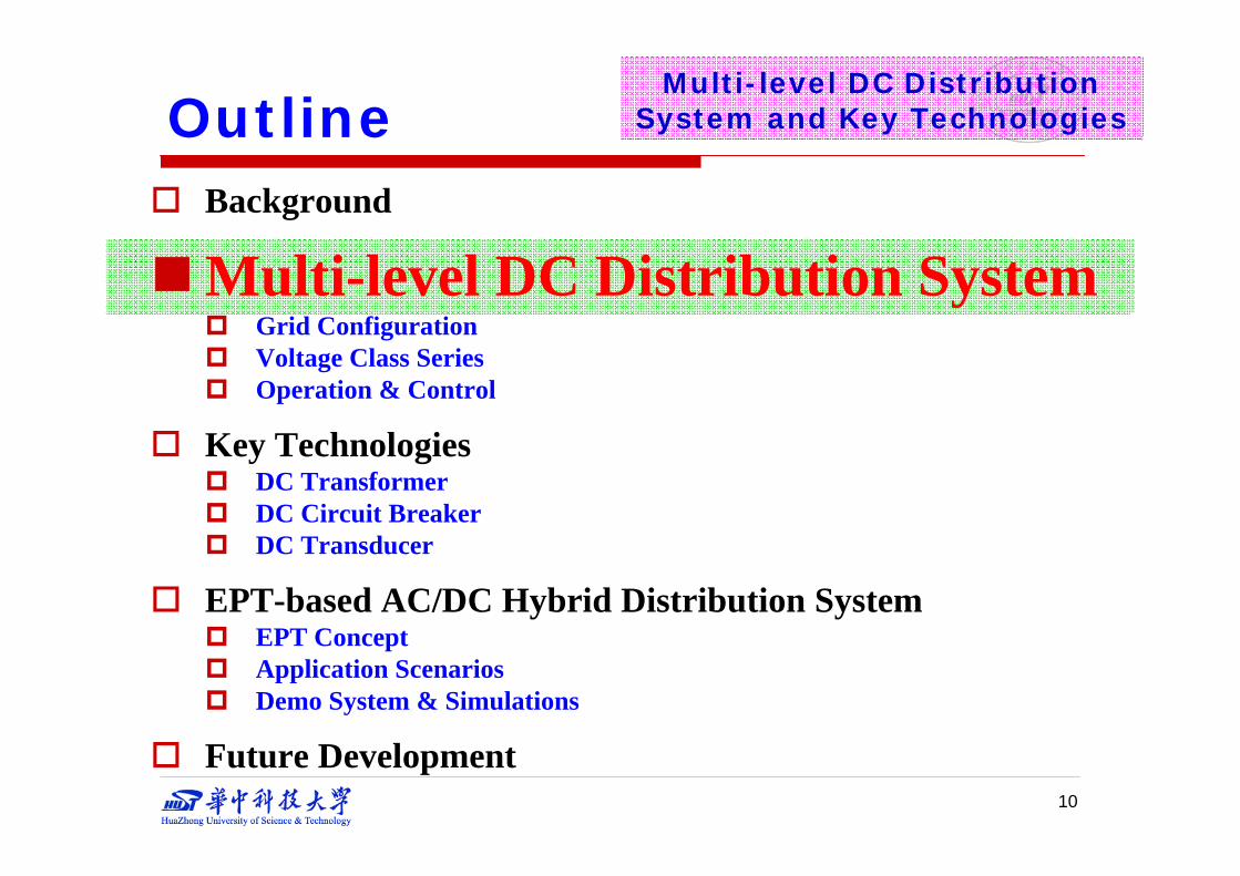
Outline Background
Multi-level DC Distribution System Grid Configuration Voltage Class Series Operation & Control
Key Technologies DC Transformer DC Circuit Breaker DC Transducer
EPT-based AC/DC Hybrid Distribution System EPT Concept Application Scenarios Demo System & Simulations
Future Development
3
Multi-level DC Distribution System and Key Technologies

Outline
Background Multi-level DC Distribution System
Grid Configuration Voltage Class Series Operation & Control
Key Technologies DC Transformer DC Circuit Breaker DC Transducer
EPT-based AC/DC Hybrid Distribution System EPT Concept Application Scenarios Demo System & Simulations
Future Development4
Multi-level DC Distribution System and Key Technologies

Background
5
Multi-level DC Distribution System and Key Technologies
Wind FarmPV
Energy StorageFuel Cell
Electric VehicleMicroturbineDC LoadsCable Transmission
Conventional AC Distribution
System
Big Challenge
DC Distribution System
Hybrid AC/DC Distribution System
。。。
Heavy Load Supply
DC Power System AC Power System DC Power System ???

Low fault rate in circuitCapability of monopole operation, which transmits part of the
power without interruptionFast responding and quick recovery Inherent self-protection of power electronics preventing internal
faults affecting external system
1
6
Lower transmission losses (no reactive power, lower resistance)More efficient for DC loadsStronger power supply relatively
2
Multi-level DC Distribution System and Key TechnologiesBackground
Advantages of DC Distribution System

7
Buried cables are superior to overhead lines in view of reliability and urban landscape.
Buried cables are superior to overhead lines in view of reliability and urban landscape.
In AC distribution, frequency and reactive power control are necessary in addition to voltage control.In AC distribution, frequency and reactive power control are necessary in addition to voltage control.
3
AC transmission via buried cables is not practical because of severe charging current.
AC transmission via buried cables is not practical because of severe charging current.
DC distribution could avoid these problems.
Multi-level DC Distribution System and Key TechnologiesBackground
Advantages of DC Distribution System

4
5
8
By instant regulation of power electronic equipments
Output of distributed sources ranges from DC to aperiodic AC and their dynamic performances vary. So it's convenient to convert outputs to DC uniformly for interconnection and control
Multi-level DC Distribution System and Key TechnologiesBackground
Advantages of DC Distribution System

9
Multi-level DC Distribution System and Key TechnologiesBackground
DC Distribution SystemAlso faced
Many challenges
Outline Background
Multi-level DC Distribution System Grid Configuration Voltage Class Series Operation & Control
Key Technologies DC Transformer DC Circuit Breaker DC Transducer
EPT-based AC/DC Hybrid Distribution System EPT Concept Application Scenarios Demo System & Simulations
Future Development10
Multi-level DC Distribution System and Key Technologies

11
Multi-level DC Distribution System——Grid Configuration
The Critical Equipments:DC TransformerDC Circuit BreakerDC CableDC Transducer…
High PerformanceHigh ReliabilityLow Cost

Topology of multi-level DC distribution system (a simple case)
12
Low voltage
Electric vehicle
AC loads
DC/ACHigh voltage
Low voltage
DC loads
AC loads
Medium voltage
Medium voltage
DC/ACDC-EPT
DC-EPT
DC-EPT DC-EPT
Small DG、 Energy storage
Large renewable sources
Rail Transit
Multi-level DC Distribution System——Grid Configuration

Satisfy power supply requirements of different levels
Allow integration of electrified railway, Electric Vehicle charging station, urban metro system, large renewable source and DG at user side
Decouple different stages of DC network
Decline power requirements of DC circuit breakers, since DC transformer(DC-EPT) can restrict rising of fault current due to its fast-responding features
Features:
13
——Grid ConfigurationMulti-level DC Distribution System

14
High load density in the future
Load Density of Major City in China in 2020
City Type Load Density(MW/km2)Developed
10~40
Developing 5~10
Undeveloped 3~5
Constraints:——Voltage Class Series
Multi-level DC Distribution System

15
The development level of related technology ( e.g. VSC-HVDC )
Profile of typical VSC-HVDC projectsProject Nation Time Rating/MW Voltage/kV Length/km
Gotland Sweden 1999 50 ±80 70
Cross Sound Cable USA 2002 330 ±150 40
Estlink Estonia-Finland 2006 350 ±150 105
Trans Bay Cable USA 2010 400 ±200 88
Shanghai China 2011 20 ±30 8
Nanao China 2013 200 ±160 32
Zhoushan China 2014 1000 ±200 134
Dalian China CIP 1000 ±320 60
DolWin1 Germany CIP 800 ±320 165
INELFE France-Spain CIP 2×1000 ±320 64
Multi-level DC Distribution System——Voltage Class Series

16
Optimization of grid structure
To optimize grid structure, DC distribution system should support DC loads without superfluous converters, so proper integration voltage class should be set for certain items.
To optimize grid structure, DC distribution system should support DC loads without superfluous converters, so proper integration voltage class should be set for certain items.
Multi-level DC Distribution System——Voltage Class Series

17
Other equipment engaged in aperiodic, non-power frequency or non-three-phase operations suggests to be supported by DC. Other equipment engaged in aperiodic, non-power frequency or non-three-phase operations suggests to be supported by DC.
Multi-level DC Distribution System——Voltage Class Series
Optimization of grid structure (cont’d)

18
Transition from traditional AC distribution system
In this case, the insulation requirement of DC voltage should be
no higher than the original AC voltage .
In this case, the insulation requirement of DC voltage should be
no higher than the original AC voltage .
Multi-level DC Distribution System——Voltage Class Series

19
Proposal of DC voltage class series:
Proposal of DC Voltage ClassVoltage Capacity Cross section Supply radius(km)
(kV) (MW) (mm2) Al Cu ±320 1024 1200 408 685 ±150 225 600 204 343 ±30 18 300 51 86 ±10 7 200 6.8 11.4
±0.75 0.04 90 3.06 5.14 0.4 0.01 60 2.04 3.43
Multi-level DC Distribution System——Voltage Class Series

20
±320 kV ,±150 kV are for the dense load demand in the future, they have stronger supply ability than 500 kV, 220 kV (in AC) respectively, and they are standard voltage-levels in domestic VSC-HVDC projects.
±30 kV meets the IEC standard that voltage ratio may be greater than 5 between 50~150 kV, and it allows integration of electrified railway andlarge renewable energy sources.
±10 kV has equal power supply ability with 20 kV(AC) while maintaining 10 kV(AC) power lines.
±750 V supports urban metro and small DGs while 400 V and 48 V support most household and enterprise appliance.
Each DC voltage has corresponding voltage in AC system, thus making it easier for interconnection and transition.
Explanations:
Multi-level DC Distribution System——Voltage Class Series

21
Steady state operation & control Transient state operation & control Stability analysis Economical operation & control Protection Reliability evaluation …
——Operation & ControlMulti-level DC Distribution System
Many AC distribution system operation & control methods can also be referenced by DC distribution system.

Outline Background
Multi-level DC Distribution System Grid Configuration Voltage Class Series Operation & Control
Key Technologies DC Transformer DC Circuit Breaker DC Transducer
EPT-based AC/DC Hybrid Distribution System EPT Concept Application Scenarios Demo System & Simulations
Future Development22
Multi-level DC Distribution System and Key Technologies

23
Requirements for DC transformer:
Safe Efficient Smart
——DC TransformerKey Technologies
DC DC
??AC AC
very easy

24
Existing schemes for DC transformer:
Conventional boost converters Cannot achieve high gain and high power Unidirectional, poor controllability
Switched capacitor converters Need too many modules to achieve high gain, which implies
significant loss and complexity
Resonant converters Increased switching losses Poor power quality Difficulties with power direction reversal
Most of these schemes are not suitable for DC distribution system because of limitation in power scale, efficiency and controllability.
——DC TransformerKey Technologies

25
EPT(Electronic Power Transformer):DC/DC
General structure of DC-EPT
Middle/high frequencytransformer
——DC TransformerKey Technologies

26
Features :
Internal MF/HF ac transformers to achieve potential isolation, bidirectional power flow and flexible phases and gain
Using cascade H-bridge (LV) or Modules Multilevel Converters (MMC) to achieve high power and reduce volume and weight of transformers and capacitors
Lowest switching losses are achieved with a step modulation to obtain high efficiency
The primary and secondary converters are blocked when dc circuit fault occurs, thus the main circuit breaker can be rated lower
——DC TransformerKey Technologies

——DC Transformer——Middle/High Frequency Transformer
Key Technologies
At present, high voltage, high power, low loss & low cost middle/high frequency transformer is still very difficult.
10kV/42kVA/1kHz middle frequency transformers
Magnetic core materials:Silicon Steel, Amorphous, Ferrite, Nanocrystalline, …

28
No current zero crossing, so DC breakers need to tolerate ultra overvoltage and current caused by generating zero crossing
fault penetration is much faster and deeper because of low impedance, hence it is necessary to clear the fault within a few milliseconds
Features of DC short circuit fault:
Key Technologies
DC circuit breaker based on LC oscillation system
——DC Circuit Breaker

29
Existing types of DC breakers:
Key Technologies——DC Circuit Breaker
30
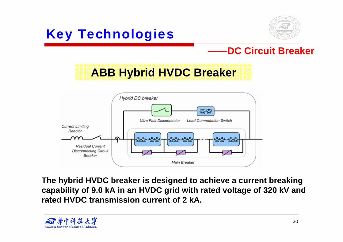
——DC Circuit BreakerKey Technologies
ABB Hybrid HVDC Breaker
The hybrid HVDC breaker is designed to achieve a current breaking capability of 9.0 kA in an HVDC grid with rated voltage of 320 kV and rated HVDC transmission current of 2 kA.

31
Proposed DC Circuit Breaker for DC distribution System
i
swidcI
2L1L1C 2C
RQB1u 2udu
Topology of the DC circuit breaker
Waveform of superimposition current
Produce current of which size and waveform can be changed flexibly to superimpose on the DC fault current
Generate artificial zero crossing & reduce positive amplitude of the superimposed current
Decrease effectively the electric-arc and damage to the switching contact
——DC Circuit BreakerKey Technologies
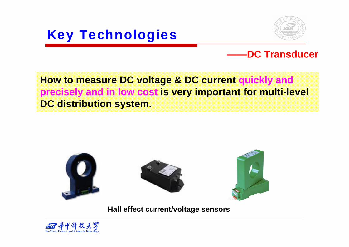
——DC Transducer
Key Technologies
How to measure DC voltage & DC current quickly and precisely and in low cost is very important for multi-level DC distribution system.
Hall effect current/voltage sensors

Outline Background
Multi-level DC Distribution System Grid Configuration Voltage Class Series Operation & Control
Key Technologies DC Transformer DC Circuit Breaker DC Transducer
EPT-based AC/DC Hybrid Distribution System EPT Concept Application Scenarios Demo System & Simulations
Future Development33
Multi-level DC Distribution System and Key Technologies

EPT-based Hybrid Distribution System
Electronic Power Transformer (EPT) A static device that transfers electrical energy from
one circuit to another through medium- or high-frequency (MF or HF) electromagnetic induction-based transformation and power electronic conversion technology.
Also named Solid State Transformer (SST) or Power Electronic Transformer (PET).
Conceptual diagram of EPT34
——EPT concept

35
In fact, EPT is now a general concept
EPT can satisfy the different requirements of different power sources and loads.
Hybrid-EPT
Interface for ac & dc
DC-EPT
DC grid application
AC-EPT
Without dc-link
AC grid application
With dc-link
AC AC
DC DC
EPT-based Hybrid Distribution System——EPT concept

Interface for dc micro-source
Interface for ac micro-source
36
EPT-based Hybrid Distribution System——Application Scenarios

Interface for AC/DC distribution system
37
EPT-based Hybrid Distribution System——Application Scenarios

Power generation by remaining heat, pressure & gas, etc.
EPT-based industry distribution system
Several systems can be interconnected to form a cluster of systems, and the loads in each system could be supplied from others.
In the large-scale industry enterprises, the conventional captive power plants may be integrated to enhance the supply reliability.
Single system Multi system
38
EPT-based Hybrid Distribution System——Application Scenarios

39
Main Parameters of the Demo System
——Demo System & SimulationsEPT-based Hybrid Distribution System

0
3000
6000
9000
12000
0 0.1 0.2 0.3
time (s)
Out
put p
ower
of P
V (W
)
Case I: Standalone state
-200
-100
0
100
200
0 0.1 0.2 0.3
time (s)
Vol
tage
of A
C b
us (V
)
0
500
1000
1500
2000
2500
3000
3500
0 0.1 0.2 0.3
time (s)
DC
load
pow
er (W
)
0
1500
3000
4500
6000
7500
0 0.1 0.2 0.3
time (s)
AC
load
pow
er (W
)
Output voltage control operating modeEPT with PV & ESS
40
time (s) time (s)
time (s) time (s)
Demo system
The PV and battery together guarantee the reliability of the power supply for critical loads
The power of PV varies from 10.1 kW to 6.8 kW at 0.2 s, while the DC bus is loaded 3 kW and the AC bus is loaded 7 kW.O
utpu
t pow
er o
f PV
(W)
Volta
ge o
f AC
bus
(V)
DC
load
pow
er (W
)
AC
load
pow
er (W
)EPT can maintain the AC bus voltage. The entire system can satisfy the load demand regardless the variations from PV.
EPT-based Hybrid Distribution System

Case II: Grid-tied state
0
3000
6000
9000
12000
0 0.2 0.4 0.6 0.8 1.0
time (s)
Out
put p
ower
of P
V (W
)
0
1000
2000
3000
4000
0 0.2 0.4 0.6 0.8 1.0
time (s)D
C lo
ad p
ower
(W)
0
2500
5000
7500
10000
0 0.2 0.4 0.6 0.8 1.0
time (s)
Pow
er fl
owin
g th
roug
h EP
T (W
)
-3000
0
3000
6000
0 0.2 0.4 0.6 0.8 1.0
time (s)
Pow
er p
rovi
ded
by u
tility
grid
(W)
Real power tracking operation mode
41
time (s) time (s)
time (s) time (s)
Both the PV and utility grid power the loads reliably and greenly
The DC loads are set at 3 kW and the AC loads are set at 7 kW.
The maximum output power of PV varies from 10.1 kW to 6.8 kW at 0.1 s, and back to 10.1 kW at 0.4 s.
And half of AC loads are switched off at 0.6 s.
Power provided by utility grid (W)Power flowing through EPT (W)
Output power of PV (W) DC load power (W)Demo system
The system can always obtain the maximum output power from the PV, and the excess power is transferred to the utility grid.
EPT-based Hybrid Distribution System

0
50
100
150
0 0.25 0.50 0.75 1.00 1.25 1.50
time (s)
RM
S vo
ltage
of A
C b
us (V
)R
MS
volta
ge o
f AC
bus
(V)
Case III: EV Powering state
-6000
-5000
-4000
-3000
-2000
-1000
0
0 0.25 0.50 0.75 1.00 1.25 1.50
Out
put p
ower
of E
V (W
)
0
500
1000
1500
0 0.25 0.50 0.75 1.00 1.25 1.50
time (s)
DC
load
pow
er (W
)
0
1000
2000
3000
4000
0 0.25 0.50 0.75 1.00 1.25 1.50
AC
load
pow
er (W
)
42
time (s)
time (s)
time (s)
time (s)
EV can enhance the power supply reliability of the critical loads in an emergency
EV can be integrated to serve as a temporary power supply.
The critical loads are set at about 4.8 kW, including DC loads 1.3 kW and AC loads 3.5 kW.
At 0.3 s, the AC loads are reduced to half.
Output voltage control operating modeEPT with EV
Out
put p
ower
of E
V (W
)
AC
load
pow
er (W
)
DC
load
pow
er (W
)
Demo system
EV can power loads through the EPT in a critical condition, and the power supply reliability would be enhanced.
EPT-based Hybrid Distribution System

Brief introduction:
10kV/400V/500kVA AC-EPT Industrial Prototype
43
By far, one 10 kV/400V/500kVA industrial prototype of AC-EPT was been developed. This valuable experience may attribute to development of DC-EPT.
EPT-based Hybrid Distribution System
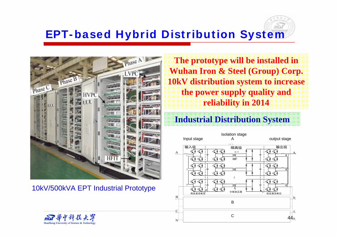
C
B
AInput stage output stageisolation stage
MF
The prototype will be installed in Wuhan Iron & Steel (Group) Corp. 10kV distribution system to increase
the power supply quality and reliability in 2014
Industrial Distribution System
10kV/500kVA EPT Industrial Prototype
44
EPT-based Hybrid Distribution System

Steady state input voltage & currents
Steady state output voltages & currents
10 kV Laboratory Experimental Results
45
EPT-based Hybrid Distribution System

Startup Loaded
46
10 kV Laboratory Experimental Results
EPT-based Hybrid Distribution System

Outline Background
Multi-level DC Distribution System Grid Configuration Voltage Class Series Operation & Control
Key Technologies DC Transformer DC Circuit Breaker DC Transducer
EPT-based AC/DC Hybrid Distribution System EPT Concept Application Scenarios Demo System & Simulations
Future Development47
Multi-level DC Distribution System and Key Technologies

Future Development
48
Future DevelopmentMulti-level DC Distribution System
Power Electronicshigh voltage & high power
low cost & low losshigh reliability
Advanced Control Strategyhigh performance
Advanced Materialless volume & low loss & low cost
DC Loadshigh efficiency
Advanced DC Transducerhigh accuracy & low cost

Background
Multi-level DC Distribution System Grid Configuration Voltage Class Series Operation & Control
Key Technologies DC Transformer DC Circuit Breaker DC Transducer
EPT-based AC/DC Hybrid Distribution System EPT Concept Application Scenarios Demo System & Simulations
Future Development49
Multi-level DC Distribution System and Key Technologies
Summary

Thanks!
50