Embed Size (px)
Citation preview
Influence of Seals with Frequency Dependent Characteristics on the Rotordynamic
Behaviour of High Pressure Compressors
Dr. Joachim Schmied, Zürich
Dr. Michael Spirig, Zürich
Dr. Norbert G. Wagner, Duisburg
Peter Critchley, London
Summary
The economic development of oil fields in increasingly difficult environments requires
unconventional technical solutions for turbo compressors which are installed for the
re-injection of the gas into the oil reservoir. In this paper a compressor rotor designed
for a discharge pressure of 1000 bar with a honeycomb seal on the balance piston is
presented and compared to the behaviour with a labyrinth seal. The force
characteristics of the seals have been measured in a special test stand designed for
this type of measurement. It is shown, that the traditional description of the forces
with constant stiffness and damping coefficients can no longer be applied in case of a
honeycomb seal. A new approach with the description of the forces by means of
transfer functions is described. The rotordynamic stability of the compressor is
analysed by modelling the seal transfer function in a similar way as it is done for a
“magnetic bearing”.
1. Introduction, Background
As oil fields deplete in the accessible regions of the world oil companies are forced to
search for oil in fields located in increasingly difficult environments, at increasing
depth below ground and remoteness from markets. These factors interact to
challenge the economic development of newly discovered fields.
Frequently the remoteness from markets leads to transportation costs which are too
high for the gas associated with the oil to be marketed economically. This gas cannot
be burnt at the well head and has to be disposed off by re-injection into the oil
reservoir. The increasing depth of the strata into which the gas is injected requires
very high well head pressures. This together with the possibility of high H2S levels
has prompted studies into the feasibility of designing compressors for these duties.
The study on which this paper is based assumed the use of a centrifugal compressor.
It also assumed a compressor discharge pressure of 1000 bar a molecular weight of
25.77 and a H2S level of 25 Mol %. On top of these extreme conditions, a “zero
emission” concept had to be developed due to installation of this unit in a most
sensitive ecological environment. These conditions are to the authors knowledge the
most severe proposed for any centrifugal compressor and were selected in order to
benchmark the boundaries of these applications. At the time of the study the highest
pressure in service was circa 650 bar although prototype technology demonstration
machines had operated successfully on test beds at beyond 900 bar /1/.
The H2S presents it's own challenge to the shaft end seal and its ancillary system.
The high pressure units in service referenced above used oil film shaft end seals.
Analysis of field experience in similar service pointed to concerns about the reliability,
operability, safety and decontamination of the seal and its ancillary oil system. Whilst
studies indicated that solutions to these challenges could be developed, at least on
paper, they were bulky, complex, costly and still presented the potential for toxic
mortality to operations and maintenance personnel.
The dry gas seal was identified as offering a more compact, simpler, cheaper and
safer solution to the problem. In order to keep within the bounds of the then current
experience the dynamic sealing pressure had to be limited to circa 250 bar with a 300
bar static pressure. These pressures also corresponded to the limit for oil film seals.
The dry gas seal contributes neither the benefit (extra support and damping) nor
liability ( poor predictability of service behaviour) of an oil film seal. The former is of
concern to the rotordynamist. The authors know of many cases where retrofitting dry
gas seals has resulted in rotors demonstrating self excited whirl of the first critical
speed when they had previously operated stable, i.e. their stable operation was only
possible with the support and damping as provided by the oil film seal.
Altogether this represented a significant challenge to the compressor industry.
The flow rate of the compressor was selected to saturate the power from a 40000 hp
ISO rating gas turbine of a heavy industrial type at typical altitudes and 5%
exceedance temperatures.
Four manufacturers were invited to submit their design proposals for consideration.
These dealt with:
• rotor dynamics and stability,
• impeller rotating stall and fatigue strength,
• asymmetric discharge scroll pressure distribution,
• rotor thrust load evaluation,
• casing mechanical design, containment, sealing, manufacture and metallurgy,
• formation in dry gas seals of condensates, hydrates and ice at casing settle out
and start up pressures at low ambient temperatures,
• equations of state for the gas,
• potential for free sulphur to precipitate from the high H2S gas,
• compressor train testing.
A solution with three compressor casings was needed. All of the compressor stages
presented their particular rotordynamic design challenges. The third casing due to
high pressure is the most critical one regarding fluid-rotor interaction.
It has a discharge density of about 430 kg/m3 which is close to that of liquid methane
which has density of 422.53 kg/m3 at atmospheric pressure. The compressibility of
the gas changes rapidly with pressure and temperature in this region of the heat
enthalpy / entropy diagram such that the volumetric flow at inlet and discharge hardly
vary. One is entitled to ask is this a compressor or a pump ?
In order to keep the sealing pressure within the bounds specified it was necessary to
balance the pressure of a chamber inboard of the dry gas seal to the suction of the
second casing at circa 250 bar. This created additional bearing span due to the
separating seal (labyrinth or honeycomb type) required inboard of the pressure
balance chamber. The recycled gas also created a significant power debit.
The ability to predict the stability of the rotor depends upon the tools used viz: the
computer codes and in particular reliable quantified data on the characteristics of the
internal impeller and balance drum seals and bearings.
The subject of this paper is an aspect of the rotor dynamics which arose during the
evaluation of the proposals. It concerns the assessment of the stability with
honeycomb seals.
The results of an analysis with the traditional direct and cross coupling stiffness and
damping coefficients showed that the rotor with honeycomb seals would become
unstable. This was puzzling and disturbing. It did not align with direct and published
experience (/2/ to /4/) and worse, if true would preclude one of the most promising
routes to solve the rotor stability problems of the three rotors. Honeycomb seals
albeit without the benefit of such precise characterisation had been successfully
applied in the past. Therefore additional analyses considering the frequency
dependent characteristic of honeycomb seals were carried out.
2. Measurement and Description of the Seal Characteristics
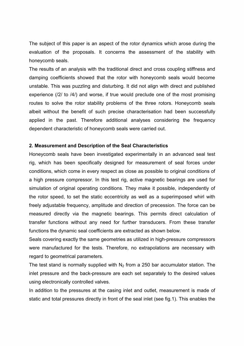
Honeycomb seals have been investigated experimentally in an advanced seal test
rig, which has been specifically designed for measurement of seal forces under
conditions, which come in every respect as close as possible to original conditions of
a high pressure compressor. In this test rig, active magnetic bearings are used for
simulation of original operating conditions. They make it possible, independently of
the rotor speed, to set the static eccentricity as well as a superimposed whirl with
freely adjustable frequency, amplitude and direction of precession. The force can be
measured directly via the magnetic bearings. This permits direct calculation of
transfer functions without any need for further transducers. From these transfer
functions the dynamic seal coefficients are extracted as shown below.
Seals covering exactly the same geometries as utilized in high-pressure compressors
were manufactured for the tests. Therefore, no extrapolations are necessary with
regard to geometrical parameters.
The test stand is normally supplied with N2 from a 250 bar accumulator station. The
inlet pressure and the back-pressure are each set separately to the desired values
using electronically controlled valves.
In addition to the pressures at the casing inlet and outlet, measurement is made of
static and total pressures directly in front of the seal inlet (see fig.1). This enables the
precise determination of the swirl at the seal inlet, which is very important because
the inlet swirl is a main influencing variable which is often only measured indirectly on
other test rigs. More details of the test rig, the identification procedure and test results
are given in /5/ and /6/.
Fig. 1: High-pressure full-scale labyrinth test rig
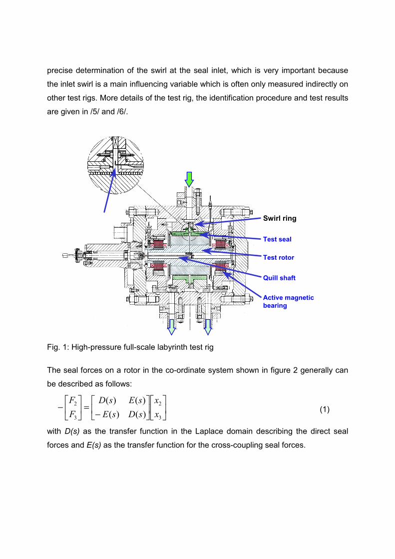
The seal forces on a rotor in the co-ordinate system shown in figure 2 generally can
be described as follows:
⎥⎦
⎤⎢⎣
⎡⎥⎦
⎤⎢⎣
⎡
−=⎥
⎦
⎤⎢⎣
⎡−3
2
3
2
)()()()(xx
sDsEsEsD
FF
(1)
with D(s) as the transfer function in the Laplace domain describing the direct seal
forces and E(s) as the transfer function for the cross-coupling seal forces.
Pitot probes Swirl ring
Test rotor
Quill shaft
Active magneticbearing
Test seal
Design pressure: 250 bar
Pressure ratio: 0.25 ... 1.0
Rotor speed: 15000 rpm
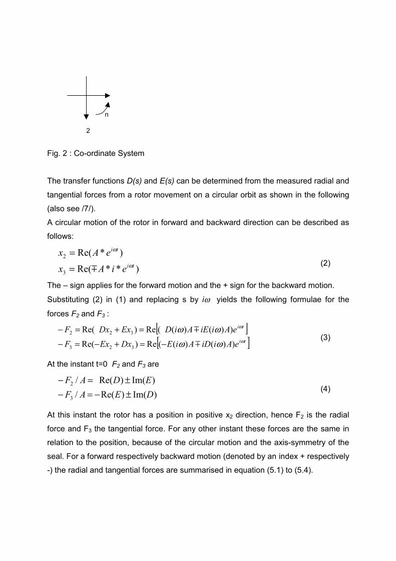
Fig. 2 : Co-ordinate System
The transfer functions D(s) and E(s) can be determined from the measured radial and
tangential forces from a rotor movement on a circular orbit as shown in the following
(also see /7/).
A circular motion of the rotor in forward and backward direction can be described as
follows:
)**Re(
)*Re(
3
2ti
ti
eiAx
eAxω
ω
!==
(2)
The – sign applies for the forward motion and the + sign for the backward motion.
Substituting (2) in (1) and replacing s by iω yields the following formulae for the
forces F2 and F3 :
[ ][ ]ti
ti
eAiiDAiEDxExF
eAiiEAiDExDxFω
ω
ωωωω
))()((Re)Re(
))()((Re)Re(
323
322
!
!
−=+−=−=+=−
(3)
At the instant t=0 F2 and F3 are
)Im()Re(/)Im()Re(/
3
2
DEAFEDAF
±−=−±=−
(4)
At this instant the rotor has a position in positive x2 direction, hence F2 is the radial
force and F3 the tangential force. For any other instant these forces are the same in
relation to the position, because of the circular motion and the axis-symmetry of the
seal. For a forward respectively backward motion (denoted by an index + respectively
-) the radial and tangential forces are summarised in equation (5.1) to (5.4).
2
3
n
)Im()Re(/ EDAFr +=− + (5.1)
)Im()Re(/ EDAFr −=− − (5.2)
)Im()Re(/ DEAFt +−=− + (5.3)
)Im()Re(/ DEAFt −−=− − (5.4)
From these equations the real and imaginary part of D and E can be expressed by
means of measured forces in radial and tangential direction:
(5.1)+(5.2) → AFFD rr /)(21)Re( −+ −−= (6.1)
(5.3)-(5.4) → AFFD tt /)(21)Im( −+ +−= (6.2)
(5.3)+(5.4)→ AFFE tt /)(21)Re( −+ −−= (6.3)
(5.1)-(5.2)→ AFFE rr /)(21)Im( −+ +−= (6.4)
It is state of the art to use frequency independent direct and cross-coupling stiffness
and damping coefficients for D and E, i.e.:
qq dikiEdikiD
ωωωω
+=+=
)()(
(7)
In this case the radial and tangential forces for forward and backward motion are:
dkDEAF
dkEDAF
qt
qr
ωω
±−=±−=−±=±=−
±
±
)Im()Re(/
)Im()Re(/(8)
The radial and tangential force depend linearly on the frequency and the stiffness
and damping coefficients can be identified by a linear curve fit to measured forces in
radial and tangential direction. The forces can either be measured from a forward or
backward motion. It is not necessary to measure both directions, since no additional
information is gained. For labyrinth seals, which were the primary target of the test
program, this assumption proved to be valid. A reliable stability analysis can be
conducted with these labyrinth stiffness and damping coefficients as demonstrated in
/8/.
However, for honeycomb seals the linear dependence no longer applies. In /9/ for
example transfer functions with a first order denominator for D and E and a first order
nominator for D and a zero order nominator for E are proposed.
General transfer functions for D and E could be gained from equations (6.1) to (6.4)
by measured tangential and radial seal forces for circular forward and backward
motions.
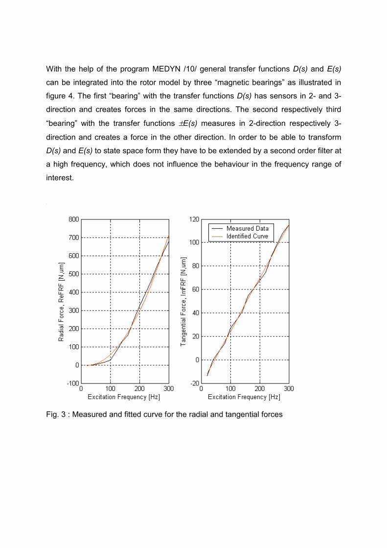
In the present case we have measured curves for a forward motion only. The curve
for the radial force clearly shows a non-linear characteristic with the frequency (fig.3).
Since we lack the backward direction, we cannot determine curves for D and E and
then directly fit a transfer function. Instead we prescribe functions for D and E, which
yields a linear dependence with frequency for the tangential and a square
dependence with frequency for the radial force:
γωβωω
**
*2*
EE
DD
KKiE
KiKD
+−=+=
(9)
→
γβωωω
**
**2
/
/
EDt
EDr
KKAF
KKAF
−=−−=−
+
+(10)
The measured and fitted curve according to 10 are shown in figure 3.
The curve fit yields the following coefficients:
KD* =229.8 Ns2/m
KE* =5360 Ns/m
γ = 388.3784 1/s
β = 314.1934 1/s
With the help of the program MEDYN /10/ general transfer functions D(s) and E(s)
can be integrated into the rotor model by three “magnetic bearings” as illustrated in
figure 4. The first “bearing” with the transfer functions D(s) has sensors in 2- and 3-
direction and creates forces in the same directions. The second respectively third
“bearing” with the transfer functions ±E(s) measures in 2-direction respectively 3-
direction and creates a force in the other direction. In order to be able to transform
D(s) and E(s) to state space form they have to be extended by a second order filter at
a high frequency, which does not influence the behaviour in the frequency range of
interest.
Fig. 3 : Measured and fitted curve for the radial and tangential forces
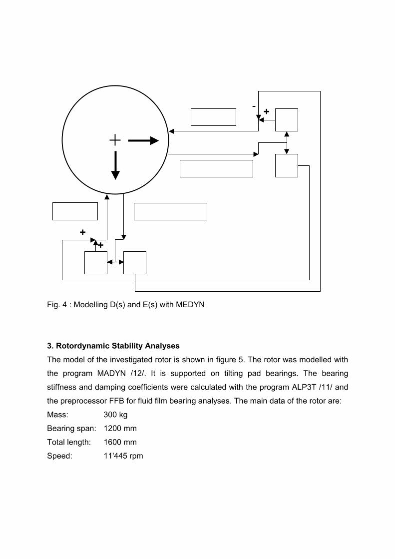
Fig. 4 : Modelling D(s) and E(s) with MEDYN
3. Rotordynamic Stability Analyses
The model of the investigated rotor is shown in figure 5. The rotor was modelled with
the program MADYN /12/. It is supported on tilting pad bearings. The bearing
stiffness and damping coefficients were calculated with the program ALP3T /11/ and
the preprocessor FFB for fluid film bearing analyses. The main data of the rotor are:
Mass: 300 kg
Bearing span: 1200 mm
Total length: 1600 mm
Speed: 11'445 rpm
Force F3
23
Displacement x2Force F2
D E+
Displacement x3
D
E
- +
+
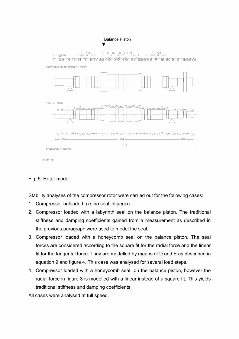
Fig. 5: Rotor model
Stability analyses of the compressor rotor were carried out for the following cases:
1. Compressor unloaded, i.e. no seal influence.
2. Compressor loaded with a labyrinth seal on the balance piston. The traditional
stiffness and damping coefficients gained from a measurement as described in
the previous paragraph were used to model the seal.
3. Compressor loaded with a honeycomb seal on the balance piston. The seal
forces are considered according to the square fit for the radial force and the linear
fit for the tangental force. They are modelled by means of D and E as described in
equation 9 and figure 4. This case was analysed for several load steps.
4. Compressor loaded with a honeycomb seal on the balance piston, however the
radial force in figure 3 is modelled with a linear instead of a square fit. This yields
traditional stiffness and damping coefficients.
All cases were analysed at full speed.
Balance Piston
Theoretically the square function for the radial force of case 3 could also have been
modelled with a damping coefficient and a negative mass. However, for full load the
negative mass becomes so huge, that the diagonal element of the mass matrix at the
location of the seal becomes negative. Most finite element programs do not cope with
such kind of systems.
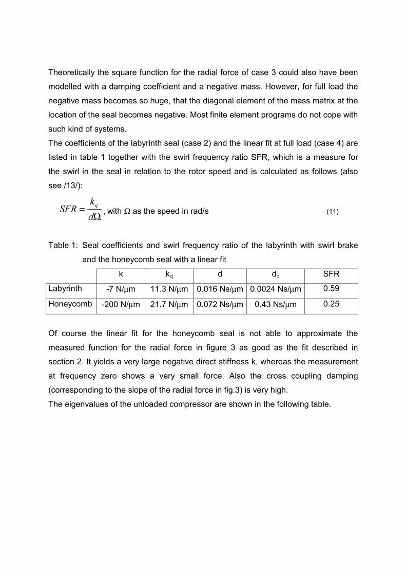
The coefficients of the labyrinth seal (case 2) and the linear fit at full load (case 4) are
listed in table 1 together with the swirl frequency ratio SFR, which is a measure for
the swirl in the seal in relation to the rotor speed and is calculated as follows (also
see /13/):
Ω=dk
SFR q, with Ω as the speed in rad/s (11)
Table 1: Seal coefficients and swirl frequency ratio of the labyrinth with swirl brake
and the honeycomb seal with a linear fit
k kq d dq SFR
Labyrinth -7 N/µm 11.3 N/µm 0.016 Ns/µm 0.0024 Ns/µm 0.59
Honeycomb -200 N/µm 21.7 N/µm 0.072 Ns/µm 0.43 Ns/µm 0.25
Of course the linear fit for the honeycomb seal is not able to approximate the
measured function for the radial force in figure 3 as good as the fit described in
section 2. It yields a very large negative direct stiffness k, whereas the measurement
at frequency zero shows a very small force. Also the cross coupling damping
(corresponding to the slope of the radial force in fig.3) is very high.
The eigenvalues of the unloaded compressor are shown in the following table.
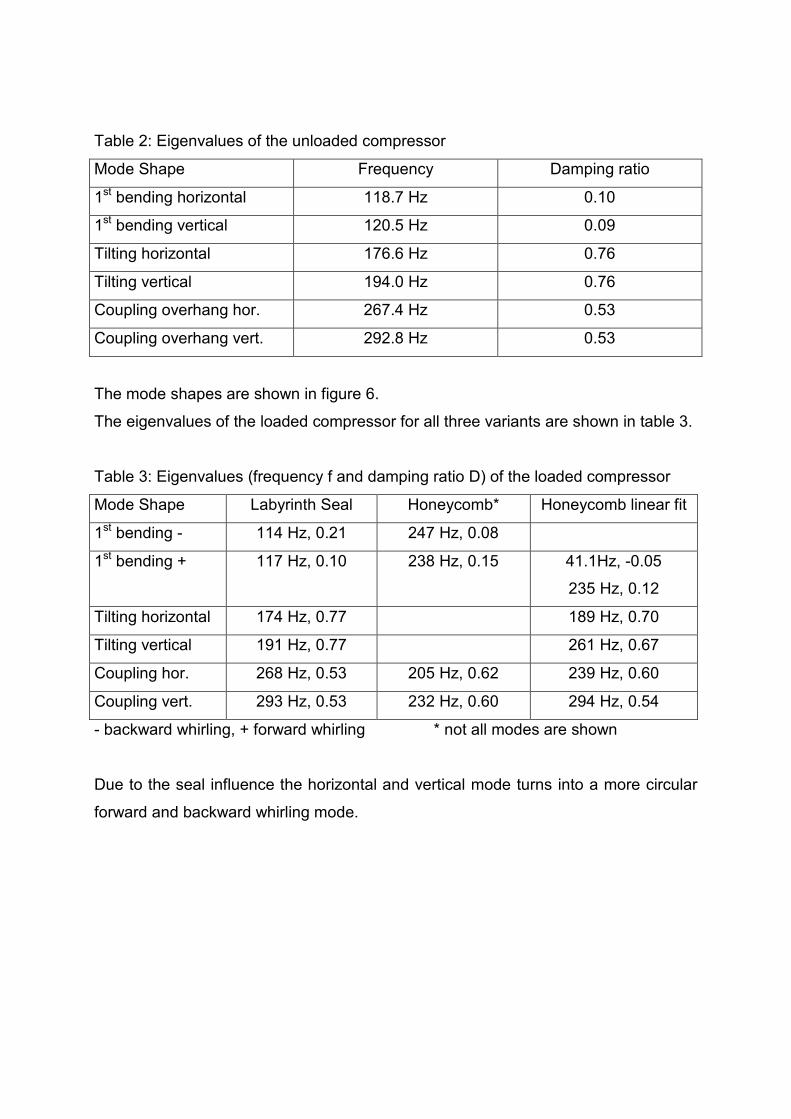
Table 2: Eigenvalues of the unloaded compressor
Mode Shape Frequency Damping ratio
1st bending horizontal 118.7 Hz 0.10
1st bending vertical 120.5 Hz 0.09
Tilting horizontal 176.6 Hz 0.76
Tilting vertical 194.0 Hz 0.76
Coupling overhang hor. 267.4 Hz 0.53
Coupling overhang vert. 292.8 Hz 0.53
The mode shapes are shown in figure 6.
The eigenvalues of the loaded compressor for all three variants are shown in table 3.
Table 3: Eigenvalues (frequency f and damping ratio D) of the loaded compressor
Mode Shape Labyrinth Seal Honeycomb* Honeycomb linear fit
1st bending - 114 Hz, 0.21 247 Hz, 0.08
1st bending + 117 Hz, 0.10 238 Hz, 0.15 41.1Hz, -0.05
235 Hz, 0.12
Tilting horizontal 174 Hz, 0.77 189 Hz, 0.70
Tilting vertical 191 Hz, 0.77 261 Hz, 0.67
Coupling hor. 268 Hz, 0.53 205 Hz, 0.62 239 Hz, 0.60
Coupling vert. 293 Hz, 0.53 232 Hz, 0.60 294 Hz, 0.54
- backward whirling, + forward whirling * not all modes are shown
Due to the seal influence the horizontal and vertical mode turns into a more circular
forward and backward whirling mode.
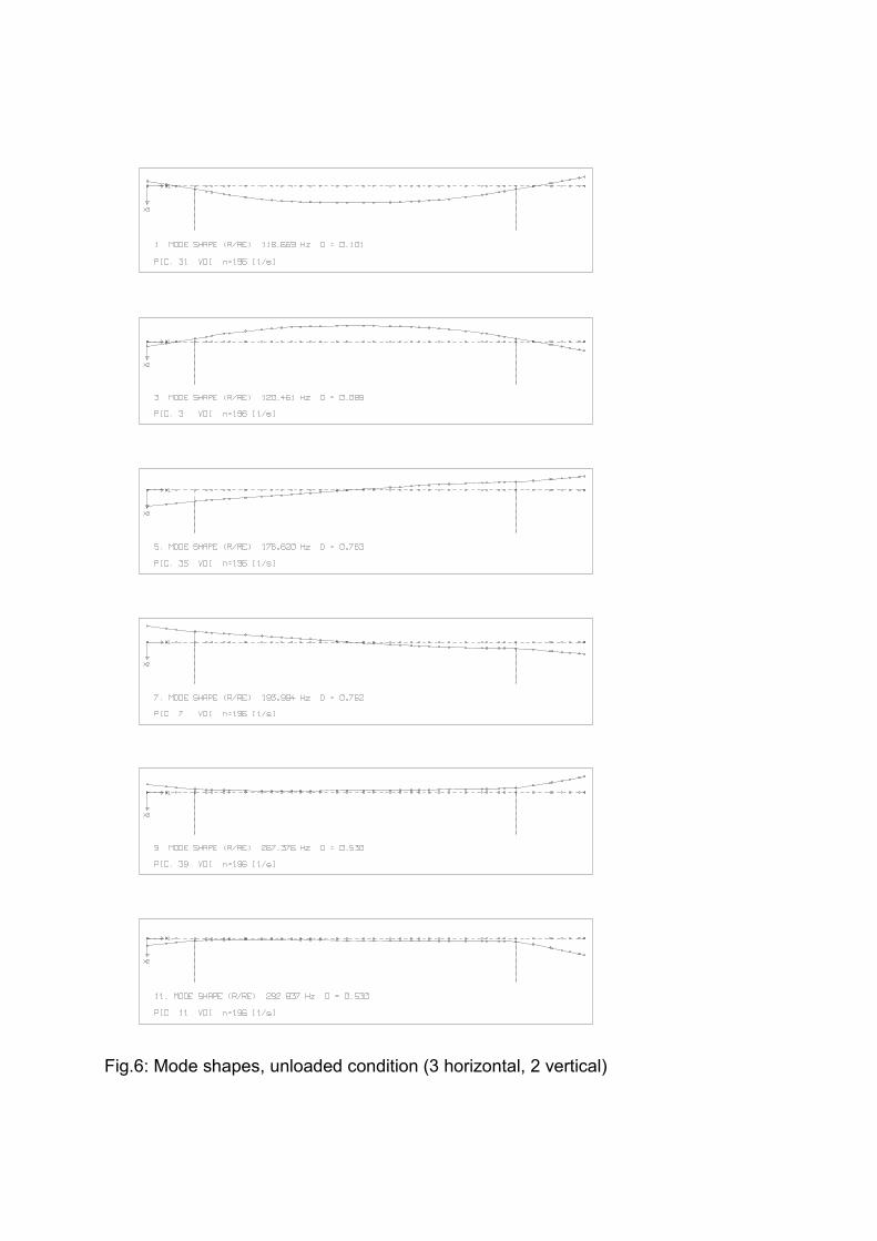
Fig.6: Mode shapes, unloaded condition (3 horizontal, 2 vertical)
The behaviour of the compressor rotor with labyrinth seal and swirl brake does not
deviate to a very large extent from the unloaded compressor and is as can be
expected from the seal coefficients in table 1. The radial forces, which are
determined by the direct stiffness k and the cross coupling damping dq, are moderate
and therefore their influence on the natural frequencies is small. The circumferential
forces d and kq do not destabilise the bending mode. This is due to the relatively low
speed in relation to the natural frequency of the bending mode, which has a ratio of
1.63 (the so called flexi ratio FR) and the swirl frequency ratio of 0.59, which is too
low to reduce the rotor damping provided by the bearings (SFR * FR = 0.96 < 1).
In case of the honeycomb seals we have a different situation: For both models for the
radial force we have a huge influence on the rotordynamic behaviour due to the
much larger seal forces especially in radial direction. Due to this influence it is difficult
to assign the modes to the original modes of the unloaded compressor. All the same
this has been done in the table as far as possible. Moreover, the behaviour with the
two seal models is completely different!
In the case of the linear fit the bending mode drops dramatically due the large
negative direct stiffness. This increases the flexi ratio to 4.64! The relatively low swirl
frequency ratio of 0.25 then is still high enough to destabilise the rotor (SFR * FR =
1.16 > 1). However, this behaviour is not realistic and does not correspond to the
measured radial force. The large negative direct stiffness of the linear fit implies a
negative radial force at low frequencies. In contrast to this the measurement shows a
very small radial force at low frequencies. This means, that the behaviour is a
consequence of the inadequate linear fit.
The results with the more adequate square fit show a dramatic increase of the
bending mode natural frequency to about twice the original natural frequency. Thus
the running speed is even below the natural frequency and the bending mode cannot
be destabilised by the seal. Interesting to note is the untypical phenomenon, that the
rotor is operating as a supercritical rotor on its maximum continuous speed unloaded
and that upon increase of gas density the natural frequency will also increase, thus
bringing the rotor into resonance with the constant operating speed. (Usually a
resonance is passed by increasing rotor speed). This behaviour isn’t critical as long
as high damping does exist. This increase of the natural frequency is absolutely
realistic. It has been observed in field tests, where honeycomb seals have been
retrofitted in order to remedy rotordynamic stability problems /3,4/. This phenomena
is analogous to that seen in centrifugal pumps where the critical speed is increased
when the rotor is running in liquid compared to running in air due to the Lomakin
effect, which has a different cause, but in some respect similar consequences. (It is
caused by flow entry and exit losses, whereas the negative mass effect is caused by
acoustics). Frequently the pump rotor critical speed is raised above the running
speed. However pumps are not normally started empty so the increasing critical
speed with density phenomena isn’t witnessed. The observation was made in the
introduction as to whether in this application we were considering a compressor or a
pump!
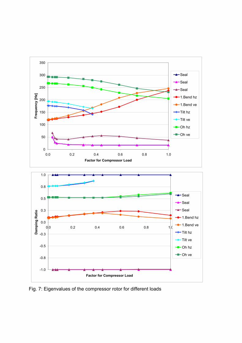
Apart from this behaviour the analysis also shows results, which cannot be
interpreted as clearly. To better understand the influence of the honeycomb seal the
eigenvalues for several load steps to full load are shown in figure 7. The diagrams
show how the bending, tilting and overhang mode change with increasing load. It can
also be seen that additional modes appear above a load factor of 0.04.
Above a load factor of app. 0.4 the tilting modes suddenly change to modes, which
can no longer be clearly described. These modes have different frequencies and are
highly damped. They are omitted in the diagram. This behaviour seems to be caused
by a relative large influence of the seal on the tilting modes, which have a large
deflection at the balance piston location.
At a relatively low load factor of 0.04 new modes (denoted by “seal” in the diagrams)
suddenly appear, which are partly unstable. These modes can be assigned to the
seal and its model. One must remember, that the square fit of the radial force has a
behaviour like a large negative mass. At full load this mass has the order of
magnitude of more than 2/3rd of the total rotor mass! (A model with a negative mass
on a spring yields a stable and unstable real eigenvalue!)
This behaviour certainly does not correspond to the real behaviour. A negative mass
means, that forces increase with the square of the frequency. A negative mass of this
amount would cause huge forces on the rotor at higher frequencies. It is likely, that
the measured curve for the radial force in figure 3 does not continue in the same way
for higher frequencies, but flattens out, as the transfer functions proposed by
Kleynhans /9/. However, this must be proven by a measurement in an extended
frequency range. Unfortunately, measurement of seal forces at whirl frequencies
significantly above 300 Hz poses real challenges to the applied testing technology!
As already mentioned in section 2, it is also desirable to measure the forces for
backward whirling modes, in order to be able to accurately identify a more general
transfer function. This could be achieved very easily on the test rig described above.
Such a measurement would also give more insight into the negative mass effect.
Since this effect is proportional to the square of the frequency its influence would be
the same for forward and backward whirling. The measured curves for radial and
tangential forces in an extended frequency range would have to be fitted with transfer
functions of most probably higher nominator and denominator order.
Further important effects on rotor stability relate to the static forces generated by the
honeycomb seals, which would not fit into the scope of this paper.
0
50
100
150
200
250
300
350
0.0 0.2 0.4 0.6 0.8 1.0Factor for Compressor Load
Freq
uenc
y [H
z]
Seal
Seal
Seal
1.Bend hz
1.Bend ve
Tilt hz
Tilt ve
Oh hz
Oh ve
-1.0
-0.8
-0.5
-0.3
0.0
0.3
0.5
0.8
1.0
0.0 0.2 0.4 0.6 0.8 1.0
Factor for Compressor Load
Dam
ping
Rat
io
Seal
Seal
Seal
1.Bend hz
1.Bend ve
Tilt hz
Tilt ve
Oh hz
Oh ve
Fig. 7: Eigenvalues of the compressor rotor for different loads
4. Conclusions
The seal influence on the rotordynamic behaviour of high pressure compressors is
substantial.
The calculated behaviour with a labyrinth seal on the balance piston with traditional
stiffness and damping coefficients, which are based on a measurement, is as
expected. The radial forces in the present case do not influence the natural
frequency of the rotor to a high extent and the damping of the bending mode is not
reduced thanks to the limited swirl in the seal in relation to the natural frequency of
the bending mode.
In case of a honeycomb seal the traditional stiffness and damping coefficients, which
are gained from a linear fit to measured forces, proved to be completely inadequate
especially for the radial direction. The results of a rotordynamic analysis show
unstable behaviour due to a large frequency drop of the first bending mode, due to a
large negative direct stiffness from the linear fit, which does not properly model the
behaviour of the radial forces at low frequencies.
Modelling the seal with a more adequate square fit for the radial forces yields a
behaviour of the bending mode as it has been observed in several tests: The natural
frequency is considerably increased and thus ensures stability of this mode.
However, the analysis with this honeycomb seal model also shows results, which are
not as clear. Some new modes, which are unstable arise. This behaviour is most
probably caused by a still insufficient seal model. A better model could be gained
from a measurement of the radial and tangential forces for an orbit in forward and
backward direction in a wider frequency range.
Although one could conclude from the present results, that the labyrinth seal is
perfectly adequate for the foreseen job and that there are still some question marks
behind the honeycomb seal, the latter still is a promising solution and should not be
forgotten for remedies of unforeseen effects in real machine in an operating range
with little experience. However, the modelling of honeycomb seals should be
improved as proposed, although some effects which have been observed in tests can
be simulated very well with the present model.
References
/1/ Demag, 1981, “Centrifugal Compressors for Ultra-high Pressures”, Company
Brochure MA 25.69 en/12.81.
/2/ Gelin, A., Pugnet, J.-M., Bolusset, D., Friez, P., 1996, “Experience in Full-Load
Testing Natural Gas Centrifugal Compressors for Rotordynamic Improvements“,
ASME-Paper 96-GT-378.
/3/ Sorokes, J.M., Kuzdzal, M.J., Sandberg, M.R., Colby, G.M., 1994, “Recent
Experiences in Full Load Full Pressure Shop Testing of a High Pressure Gas
Injection Centrifugal Compressor”, Proc. of the 23rd Turbomachinery Symposium
/4/ Zeidan, F.Y., Perez, R.X. and Stephenson, E.M., 1993, “The Use of Honeycomb
Seals in Stabilizing Two Centrifugal Compressors“, Proc. of the 22nd
Turbomachinery Symposium
/5/ Wagner, N.G., 2001, „Methode zur Identifikation der dynamischen Labyrinth-
koeffizienten für Hochdruckverdichter mit Hilfe aktiver Magnetlager“, Dissertation,
TU Darmstadt, published as Fortschritt-Berichte VDI, Reihe 11, Nr. 295.
/6/ Wagner, N.G., Steff, K., 1996, “Dynamic Labyrinth Coefficients from a High-
Pressure Full-Scale Test Rig Using Magnetic Bearings, Rotordynamic Instability
Problems in High-Performance Turbomachinery”, NASA Conf. Publ. 3344, pp.95-
112
/7/ Ulrich Bolleter et. al., 1987, ” Measurement of Hydrodynamic Interaction Matrices
of Boiler Feed Pump Impellers”, ASME Journal of Vibration, Stress and Reliability
in Design, Vol. 109, April 1987.
/8/ Wagner, N.G., de Jongh, F.M., Moffat, R., 2000, “Design, Testing and Field
Experience of a High-Pressure Natural Gas Reinjection Compressor”,
Proceedings of the 29th Turbomachinery Symposium in Houston, September 19-
21, 2000
/9/ George F. Kleynhans, Dara W. Childs, 1996, “ The Acoustic Influence of Cell
Depth on the Rotordynamic Characteristics of Smooth Rotor / Honeycomb-Stator
Annular Gas Seals”, ASME paper No. 96-GT-122, presented at the ASME Turbo
Expo, Birmingham, UK, 1996.
/10/J. Schmied, F. Betschon, 1998, ” Engineering for Rotors Supported on Magnetic
Bearings”, Proceedings of the 6th International Symposium on Magnetic
Bearings, August 5-7, Boston 1998.
/11/ N. Mittwollen, 1997, „Taschenlager-Optimierung“, FVV-Bericht Vorhaben Nr.339,
TU Braunschweig und FVV Frankfurt, 1987.
/12/ Ingenieurbüro Klement, 1998, „MADYN Machine Dynamics Program System“
(Version 4.2)“, Description Manuals.
/13/ Dara Childs, 1993, “Turbomachinery Rotordynamics”, Wiley Inter Science.

![UM2011 Schmied [Kompatibilit tsmodus] · 2013. 1. 5. · CADFEM User's Meeting 2011 Schmied Engineering GmbH 1 Erdbebennachweise von Starkstromkomponenten Sebastian Kurmann und Beat](https://img.pdfslide.net/doc/110x75/6103777b920ace1f4a1b3ece/um2011-schmied-kompatibilit-tsmodus-2013-1-5-cadfem-users-meeting-2011-schmied.jpg)