Embed Size (px)
Citation preview

Published in separate English, French, Russian and Spanish editions by theINTERNATIONAL CIVIL AVIATION ORGANIZATION999 University Street, Montréal, Quebec, Canada H3C 5H7
For ordering information and for a complete listing of sales agentsand booksellers, please go to the ICAO website at www.icao.int
10044, AN/514.edition 2016
Manual on the Aeronautical Mobile Airport Communications System (AeroMACS)
ICAO Doc 10044, Manual XXXXXOrder Number: 8896ISBN 978-92-9231-828-4
© ICAO 20XXX
All rights reserved. No part of this publication may be reproduced, stored in aretrieval system or transmitted in any form or by any means, without priorpermission in writing from the International Civil Aviation Organization.

FOREWORD
1. XXXXXXXXXXXXXX
2. XXXXXXXXXXXXXXX
___________________
(v)
TABLE OF CONTENTS
Page
Glossary…………………………………………………………………………………………………………………… #-#Terms and Abbreviations ………………………………………………………………………………………………References……………………………………………………………………………………………………………….
Chapter 1. General.............................................................................................................................................. 1-1
1.1 Introduction1.2 Background Information........................................................................................................................ 1-11.3 AeroMACS Overview………………………………………………………………………………………….1.4 Constraints, Restrictions, and limitations on AeroMACS Use…………………………………………….
Chapter 2. Guidance Material .......................................................................................................................... 2-1
2.1 Concept of Operations.......................................................................................................................... 2-12.2 System Architecture ............................................................................................................................. 2-12.3 Implementation .................................................................................................................................... 2-42.4 Prioritisation and Quality of Service...................................................................................................... 2-222.5 Hand-off (AT4 wireless genericised)..................................................................................................... 2-242.6 Frequency Allocation and Channelization2.7 Sensitivity2.8 Sub-Network Entry and Scanning Time2.9 Security2.10 Routing and Discovery2.10 Upper Layer Interfaces2.11 System Management
Chapter 3. Technical Specifications................................................................................................................. 3-1
3.1 Performance......................................................................................................................................... 3-13.2 Hand-off................................................................................................................................................ 3-13.3 Routing and discovery............................................................................................................. 3-13.4 Security framework – certificate profiles............................................................................................... 3-33.5 Prioritisation.......................................................................................................................................... 3-73.6 Upper layer interfaces........................................................................................................................... 3-113.7 Frequency allocation and Channelization............................................................................................. 3-12
___________________
(vi)

GLOSSARY
.
TERMS AND ABBREVIATIONS
Access Service Network (ASN). A system comprised of an access gateway providing an IP interface and at least one Base Station (BS)
Adaptive modulation. A system’s ability to communicate with another system using multiple burst profiles and a system’s ability to subsequently communicate with multiple systems using different burst profiles.
Aerodrome. A defined area on land or water (including any buildings, installations and equipment) intended to be used either wholly or in part for the arrival, departure and surface movement of aircraft.
Aeronautical Mobile Airport Communications System (AeroMACS). A high capacity data link supporting mobile and fixed communications on the aerodrome surface.
AeroMACS downlink (DL). The transmission direction from the base station (BS) to the mobile station (MS).
AeroMACS uplink (UL). The transmission direction from the mobile station (MS) to the base station (BS).
AeroMACS handover. The process in which a mobile station (MS) migrates from the air-interface provided by one base station (BS) to the air-interface provided by another BS.
Base station (BS). A generalized equipment set providing connectivity, management, and control of the mobile station (MS).
Bit error rate (BER). The number of bit errors in a sample divided by the total number of bits in the sample, generally averaged over many such samples.
Burst profile. Set of parameters that describe the uplink or downlink transmission properties. Each profile contains parameters such as modulation type, forward error correction (FEC) type, preamble length, guard times, etc.
Convolutional turbo codes (CTC). Type of forward error correction (FEC) code.
Data transit delay. In accordance with ISO 8348, the average value of the statistical distribution of data delays from the time that the data enters the AeroMACS network until the data exits the AeroAMACS network. This delay represents the subnetwork delay and does not include the connection establishment delay.
1-1

1-2
Domain. A set of end systems and intermediate systems that operate according to the same routing procedures and that is wholly contained within a single administrative domain.
Forward error correction. The process of adding redundant information to the transmitted signal in a manner which allows correction, at the receiver, of errors incurred in the transmission.
Frequency assignment. A logical assignment of centre frequency and channel bandwidth programmed to the base station (BS).
H-NSP: Home-Network Service Provider. A network service provider with which an AeroMACS subscriber has a contractual agreement for service.
Multiple-Input Multiple-Output (MIMO): A system employing at least two transmit (Tx) antennas and at least two receive (Rx) antennas to improve the system capacity, coverage, or throughput [12].
Mobile station (MS). A station in the mobile service intended to be used while in motion or during halts at unspecified points. An MS is always a subscriber station (SS).
Network Access Provider (NAP): Network Access Provider (NAP). NAP is a business entity that provides AeroMACS radio access infrastructure to one or more AeroMACS Network Service Providers (NSPs). A NAP implements this infrastructure using one ASN.
Network Link Establishment: A state achieved once an MS receives a DSA-ACK message.
Network Service Provider (NSP): NSP is a business entity that provides IP connectivity and AeroMACS services to AeroMACS subscribers compliant with the Service Level Agreement it establishes with AeroMACS subscribers. To provide these services, an NSP establishes contractual agreements with one or more NAPs. Additionally, an NSP MAY also establish roaming agreements with other NSPs and contractual agreements with third-party application providers (e.g., ASP or ISPs) for providing AeroMACS services to subscribers. From an AeroMACS subscriber standpoint, an NSP MAY be classified as Home NSP (H-NSP) or Visited NSP (V-NSP).
Orthogonal Frequency Division Multiplexing (OFDM). Orthogonal frequency-division multiplexing (OFDM) is a method of digital modulation in which a signal is split into several narrowband channels at different frequencies.
OFDM Symbol. In AeroMACS, a waveform with a given amplitude and phase that persists for a fixed period of time representing an integer number of bits.
Partial usage sub-channelization (PUSC). A technique in which the orthogonal frequency division multiplexing (OFDM) symbol subcarriers are divided and permuted among a subset of sub-channels for transmission, providing partial frequency diversity.
Residual error rate. The ratio of incorrect, lost and duplicate subnetwork service data units (SNSDUs) to the total number of SNSDUs that were sent.

Chapter 1. Meteorological Service for International Aviation 1-3
Service data unit (SDU). A unit of data transferred between adjacent layer entities, which is encapsulated within a protocol data unit (PDU) for transfer to a peer layer.
Service flow. A unidirectional flow of media access control layer (MAC) service data units (SDUs) on a connection that is providing a particular quality of service (QoS).
Sub Network Entry Time. The time from when the MS starts the scanning for DL, until the network link establishes the connection, and the first network user “PDU “ can be sent.
Subscriber station (SS). A generalized equipment set providing connectivity between subscriber equipment and a base station (BS).
Subnetwork entry time. The time from when the mobile station starts the scanning for BS transmission, until the network link establishes the connection, and the first network user “protocol data unit “ can be sent.
Subnetwork service data unit (SNSDU). An amount of subnetwork user data, the identity of which is preserved from one end of a subnetwork connection to the other.
Symbol. A symbol is a waveform, a state or a significant condition of the communication channel channel representing an integer number of bits, that persists for a fixed period of time.
Time division duplex (TDD). A duplex scheme where uplink and downlink transmissions occur at different times but may share the same frequency.
V-NSP: Visited-Network Service Provider. A network service provider which provides an AeroMACS subscriber with service without a direct contractual agreement for service.
WMF: WiMAX Forum
REFERENCES
[1] WiMAX Profile T23-001-R010v90 [2] WiMAX CRSL 17.0.0[3] AeroMACS CRSL v1.0[4] AeroMACS PICS v1.1[5] AeroMACS Profile Analysis [6] AeroMACS MOPS 2012-09-15[7] IEEE Std 802.16-2009[8] AeroMACS SARPS[9] ICAO annex Volume 4, sections 3.1.1.7.14.1 and 3.1.1.7.14.2.[10] Doc9863 ACAS Guidance Material section 3.5.2.1., “Multipath from terrain reflections.”[11] previous SARPs draft.[12] IEEE 802.16-2009, pp. 94, section 3.44, Definition of MIMO.[13] WiMAX Forum® Air Interface Specifications:

1-4
[14] WiMAX Forum® Mobile Radio Specification WMF-T23-005-R015v07
___________________

Chapter 1
GENERAL
1.1 INTRODUCTION
1.1.1 AeroMACS (Aeronautical Mobile Airport Communication System) is an ICAO standardised data link system aiming to support the communication exchanges dealing with the safety and regularity of flight operations in the aerodrome (airport) environment.
1.1.2 AeroMACS is based on a modern (4th Generation, 4G) mobile wireless communication system providing broadband connectivity on the airport surface. AeroMACS can support the integration of the safety and regularity of flight communications of Aircraft Operators, Air Navigation Service Providers and Airports Authorities by providing high bandwidth and prioritised communication exchanges over a common infrastructure dedicated to critical communication exchanges in the airport environment.
1.1.3 AeroMACS systems can operate in the 5030 to 5150 MHz band under the ITU allocation for AMS(R)S type of services (offering protection from interference from unauthorised users of the band).
1.1.4 The AeroMACS Technical Manual complements the AEROMACS SARPS (Annex 10 Volume III) and aims to provide guidance to regulators, manufacturers and system integrators for the deployment and configuration of AeroMACS systems. The scope of the material includes information on the concept of operations, architecture specifications and guidelines on siting, frequency allocations and interfacing.
1.1.5 Chapter 1 of the Manual covers an overview, some background information and key features of AeroMACS.
1.1.6 Chapter 2 contains the guidance material for issues typically arising in AeroMACS deployments such as applicable services, medium access configuration, BS siting, frequency allocation, architecture and interfaces to network layers. (Revisit once manual editing complete.
1.1.7 Chapter 3 of the Manual describes the technical specifications as required from sections in the guidance material.

1-2
1.2 BACKGROUND INFORMATION
1.2.1 The recommendation for AeroMACS comes from the outcome of the EUROCONTROL and FAA/NASA coordination activity called Action Plan 17 (AP17), Future Communications Study , which outlined guidelines and recommendations for the operational requirements of the Future Communication Infrastructure (FCI) composed of radio systems, networks and applications to support future aeronautical operations. AP17 estimated that the future operations are expected to generate significant data link throughput requirements which will increase heavily due to new applications being developed in R&D programs such as SESAR and NextGen. Therefore AP17 concluded that a new communications infrastructure will be required to support the future communication exchanges and recommended that FCI needs to also include current systems (analogue voice and VDL2). AP17 recommended the introduction of three new data link systems: a new SATCOM system, a new terrestrial system, in particular for the En-route and Terminal areas of operation and a new system for the airport surface in particular, where the volume of the exchanges is expected to be more significant compared to other flight areas.
1.2.2 AeroMACS is the AP17 proposed FCI data link for the airport surface and is based on the IEEE 802.16 standard delivering an ATN/IP high data rate radio link to enable future services including:
Air Traffic Services (ATS), which includes the safety critical communications related to aircraft.
Aeronautical Operational Control (AOC), which include airline communications between aircraft and the Airline operational control center and which are linked to the safety or regularity of flight.
Airport Authority communications that affect the safety and regularity of flight involving vehicles, ground services and sensors.
1.2.3 The choice of AeroMACS, based on an open standard used for commercial communications (operating in other bands), highlights the underlying objective of aviation and ICAO in particular to capitalise on existing technologies and benefit of past development efforts. This approach leverages existing commercial off the shelf (COTS) industry products and relies on existing commercial standards such as Internet Protocol (IP Doc 9896) for aviation communications.
1.2.4 As a result of ITU WRC-07 conference, AeroMACS has received an AM(R)S allocation in the 5 GHz band and is therefore eligible to make use of the protected spectrum in the 5 GH band for the safety of life and regularity of flight services.
1.3 AEROMACS OVERVIEW
1.3.1 In summary, the potential benefits from using AeroMACS include:
higher throughput in airport surface communications
providing relief on the congested VHF spectrum in airports;
worldwide interoperability and integration of critical coms for ANSPs, Airspace Users and Airports
synergies through the sharing of infrastructure ;
increased security capabilities
support/enable reducing airport congestion and delays and enhancing situational awareness of controllers
1.3.2 AeroMACS is an important data link for aviation as it is the first new pillar of a wider future aviation COM infrastructure (FCI) and in addition is a test case for aviation in:
leveraging on commercial communication developments and technologies
pooling synergies between ANSPs, Airports & Airlines
handling the security issues of future aviation COM infrastructure and
implementing IP datalink on-board aircraft
1.3.3 AeroMACS is a wideband mobile radio specification that enables cell networking through wireless communication between a set of Base Stations (BSs) and Mobile Stations (MSs). The allowed radio channel bandwidth is 5 MHz. The waveform is based on OFDM modulation, which provides resistance to dispersive propagation environments, and an OFDMA media access scheme that allows point to multipoint transmission between a BS and multiple subscribers simultaneously with given quality of service (QoS). In addition to, this an adaptive modulation scheme is used in which throughput is gradually reduced as propagation conditions deteriorate. When the fastest modulation scheme is used, throughput of approximately 3.5 Mbps in the downlink direction and approximately 1.7 Mbps in the uplink direction can be achieved.
1.3.4 The MSs are part of the Customer Premise Equipment (CPE), embedded in the aircraft providing an IP interface for the airborne network. BSs configure the cell planning, manage the channel assignment and access to the radio media in the cellular network. The Access Service Network (ASN) consists of at least one BS and one or more ASN Gateways. The ASN functional block is in charge of managing overall radio access aspects and provides an IP interface that facilitates the integration with the ATN network and services. AeroMACS security features include mechanisms for authentication, authorization and encryption .
1.3.5 An AeroMACS cellular system can potentially support a wide variety of IP data, video, and voice communications and information exchanges among mobile and fixed users at the airport. The airport Communications, Navigation, and Surveillance (CNS) infrastructure that

1-4
supports Air Traffic Management (ATM) and Air Traffic Control (ATC) on the airport surface can also benefit from secure wireless communications supporting improved availability and diversity. A wideband communications network can enable sharing of graphical data and near real-time video to significantly increase situational awareness, improve surface traffic movement to reduce congestion and delays, and help prevent runway incursions. AeroMACS can provide temporary communications capabilities during construction or outages, and reduce the cost of connectivity. A broadband wireless communications system like AeroMACS can lead to enhanced collaborative decision making, ease updating of large databases, provide up-to-date weather graphics and aeronautical information (Aeronautical Information and Meteorological Services), and enable aircraft access to System Wide Information Management (SWIM) services, Collaborative Decision Making (CDM) message transactions and delivery of time-critical advisory information to the cockpit.
1.3.6 Research and validation of the AeroMACS technology has been carried out by coordination of the EUROCAE WG-82 and RTCA SC-223 working groups. The result of this joint effort has led to the publication of an AeroMACS Profile, stating the list of technical items mandated to be supported by the radio interface as referred to in the IEEE 802.16 standard in order to guarantee radio interoperability. In addition, EUROCAE and RTCA jointly developed an AeroMACS Minimum Operational Performance System (MOPS) specifying the functional features of the AeroMACS Profile, and describing the environmental conditions and test cases required for aeronautical use. Finally, the AeroMACS Minimum Aircraft System Performance Specification (MASPS) <to be> published by EUROCAE describes a set of system performance requirements and outlines possible implementation options (architectures, use cases) for AeroMACS.
1.3.7 A commercialized version of the IEEE 802.16 standard is specified under the WiMAX brand and by the WiMAX Forum® (an industry-led, not-for-profit organization that certifies and promotes interoperability of products based on IEEE 802.16 family of standards) The WiMAX Forum in collaboration with the EUROCAE WG-82 and RTCA SC-223 Working Groups has also been supporting the standardisation of AeroMACS. The WiMAX ForumAviation Working Group has overseen the completion of the Protocol Implementation Conformance Statement (PICS) and Certification Requirements Status List (CRSL) documents and is now addressing network architecture and security aspects.
1.3.8 Finally the ARINC Airline Electronics Engineering Committee (AEEC) is working to define an ARINC avionics standard to cover the form, fit and function characteristics for the AeroMACS airborne transceiver and interfaces with other systems on-board the a/c.

1.4 CONSTRAINTS, RESTRICTIONS AND LIMITATIONS ON AEROMACS USE
1.4.1 This section is summarising the constraints associated with using AeroMACS in the airport surface. These constraints cover: spectrum, services, a/c application domains, velocity, airborne use and operation areas in the airport.
1.4.1.1 Spectrum: AeroMACS systems can operate in the band of 5030 to 5150 MHz, under an ITU AM(R)S allocation. Currently the 5091 to 5150 is targeted internationally for AeroMACS operations. However, the system can also operate in the frequency range between 5000-5030 MHz should an administration authorize AeroMACS licenses in these frequency bands.
Note: it is recommended that AeroMACS radios are manufactured to cover the band 5000-5150 MHz to cover all current and future allocations.
1.4.1.2 Services: AeroMACS operates under an ITU AM(R)S allocation. Therefore AeroMACS networks can only support services that are relevant to the safety of life or the regularity of flight operations. AeroMACS can support exchanges from all key stakeholders in an aerodrome including key stakeholders: ANSPs (safety communications), Aircraft Operators (AOC, regularity of flight communications) and Airport Authorities (regularity of flights communications).
1.4.1.3 Airborne use: AeroMACS transmissions from an aircraft are only allowed when the a/c is on the airport surface. This limitation is based on studies presented in WRC2007 in order to avoid interference to FSS (Fixed Satellite Service) systems and is part of the conditions agreed in order to obtain the allocation in the 5091 to 5150 MHz band. Therefore AeroMACS transmissions from airborne aircraft are to be inhibited.
Note: It is possible that this restriction maybe revisited by ITU in the future if new analysis and evidence will be provided for consideration.
1.4.1.4 Velocity: AeroMACS is intended for operations involving aircraft and vehicles moving at all velocities up to 50 nautical miles per hour in relation to the base station.
1.4.1.5
1.4.1.6 Airport domains: AeroMACS systems can support communications exchanges between moving and fixed assets in various operating areas in the airport environment including gate, ramp, taxiways and runways.

1-6
Chapter 2
GUIDANCE MATERIAL
2.1 CONCEPT OF OPERATIONS
2.1.1 Introduction
2.1.1.1 AeroMACS can potentially support the wide variety services of voice, video, and data communications and information exchanges among fixed and mobile users at the airport.
2.1.1.2 The applications and communications provided by AeroMACS can generally be grouped into three major categories: Air Traffic Services (ATS ), Airline Operational Control (AOC) Services and Airport Authority Services (see Figure 1). Within these broad categories, the data communications and applications can be described as either fixed or mobile, based on the mobility of the end user.
Figure 1: Examples of AeroMACS Applications
2.1.1.3 The application that a user will be connected to vary depending on the usage. The AAA services within the CSN network will authorize the data flows over AeroMACS for the users’ SS based on certificate established within the AAA. For instance aircraft, which are mobile assets, are expected to have connectivity to both Air Traffic Services group of applications as well as Airline Operational Control group of applications and may have connection to Airport Authority group of applications such as Aircraft de-icing. Airport Sensor systems, which are generally fixed assets, are expected to connect an Airport Authority type of application such as Security Video. Nomadic and non-aircraft Mobile system may have connections to all three of the above cited groups of applications depending on their needs and authorizations. Determination of the type of user SS is critical to providing the correct level of service over AeroMACS.

Figure 2 AeroMACS Generic Applications and Communications overview
2.1.2 Services
2.1.2.1 The operations that are described in the following scenarios are handled through various datalink services offered at airports, which are to be supported by AeroMACS.
2.1.2.2 Air Traffic Services
2.1.2.2.1 Air traffic services are provided to regulate air traffic to ensure safe conduct of flight operations. Air traffic services can be grouped under 8 major categories:
Data Communication Management Services ( DCM) Clearance/Instruction Services (CIS) Flight Information services (FIS) Advisory Services ( AVS) Flight Position/Intent Preference Services (FPS) Emergency Information Services (EIS) Delegated Separation Services (DSS) Miscellaneous Services (MIS)
2.1.2.2.2 Most of the ATS services that are accessible at airport terminal areas may use AeroMACS as the primary network.

1-8
2.1.2.3 Aeronautical Operational Control Services
2.1.2.3.1 Generally, Aeronautical Operational Control Services (AOC) refer to a set of datalink applications used to exchange messages between aircraft and airline centers or its service partner centers on ground. AOC is comprised of standard messages defined by AEEC standards, as well as airline defined proprietary messages. AOC improves the overall operational efficiency of flights
2.1.2.4 Airport Authority Services
2.1.2.4.1 Generally , the Airport Authority Services refers to a set of applications that is used to operate and control the airport. Information on the status of runways, facilities, airport security, etc are provided.
2.1.3 Operational Scenario
2.1.3.1 Aircraft operations at airport terminal areas can be classified under three major scenarios namely,
- Aircraft Landing - Aircraft parked @ Aprons- Aircraft departure
2.1.3.2 Aircraft operations at hangers can be considered similar to Aircraft @ Apron scenario in the context of AeroMACS network. Throughout each of these scenarios Air Traffic Services and Airlines Operational Control communications will take place.
2.1.3.3 These scenarios happen in a sequence of repeated cycles in airports as shown in the Figure 0-3 below. (En-route communications is not important for the discussion as AeroMACS is not involved in that scenario)
Figure 0-3 Aircraft operational Scenarios
2.1.3.4 . These sequences happen in continuous cycles for an aircraft during its normal operations (say from 6:00 AM to 10PM). Hence in an airport if there are around 200 arrivals and take offs per hour, at least 100 cycles of the above operational sequences occur in that airport in that hour. We can assume a
Aircraft Landing
Aircraft Parked
Aircraft Departure
Enroute

halting period of 8 hours per overnight stay for an aircraft at airports.
The individual scenarios are expanded in the following sub sections.
2.1.3.5 Aircraft Landing
2.1.3.5.1 Aircraft Landing scenario refers to the operations performed by an aircraft from its touchdown to taxiing till Gate. On touchdown, aircraft establishes datalink connectivity with the Airport Network. (The Airport network is based on AeroMACS service). The services that the aircraft is likely to be connected to are as follows:
D-TAXI (Data Link – Taxi) route plan is uploaded to Aircraft. (ATC) OOOI (Off/Out/On/In) status is provided. ( AOC) ACM (ATC Communications Management) Transfer of control happens from Runway Tower to
Ground Tower. ( ATC) A-SMGCS (Advanced Surface Movement Guidance and Control System) Surface services are
activated in addition to surface surveillance information being provided to aircraft. ) (ATC) TAXI clearances are provided. ( ATC- ground Tower) Flight Data is downloaded to Airline Operations / Maintenance centers (AOC).
At this point aircraft reaches the Gate.
2.1.3.6 Aircraft parked
2.1.3.6.1 The Aircraft Parked scenario refers to the operation performed, when an aircraft is parked at the gates, its engines are switched off and some upkeep operations are being performed. In this scenario, aircraft will be connected to Airport, ANSP and Airline Private Networks while exchanging data through the AeroMACS access network. The Services that an aircraft is likely to be connected to are as follows:
Avionics Software and Database are uploaded. These databases include airport information, Navigational data, pilot manuals, Terrain data etc.,
Maintenance data from Avionics/Engine are downloaded if not downloaded during the Aircraft Landing above. This data may include both prognostics and diagnostics information.
Pilot manuals/Charts/maps etc., may be uploaded. Electronic checklist / EFB updates may happen. Routine maintenance checks may happen.
2.1.3.7 Aircraft Departure
2.1.3.7.1 In Aircraft Departure scenario, all operations from pre-departure phase to Take Off phase are covered. Aircraft pushes back from the gate, starts engines, taxies to the runway and then takes off Aircraft remain connected to AeroMACS network till its take off. The services that the aircraft is likely to be connected to are as follows:
flight plan Airport Terminal Information Messages (ATIS),which provides information about the availability of
active runways, approaches, weather conditions, NOTAMS etc . Departure clearance Runway Visual range information, Hazardous Weather and Operational Terminal information Weight and Balance information Flight preparations, delays, pilot preferences OOOI messagesD-TAXI/ Push Back clearances TAXI route information and instructions Surface Surveillance Guidance Control ACM messages Any other information related to the regularity and safety of flight.

1-10
2.1.3.7.2 On Take Off, aircraft disconnects from the AeroMACS network.
2.1.3.8 The Scenarios in Practice
2.1.3.8.1 This section describes typical scenarios for the use of the AeroMACS communications system. Within this document, the use of other communications systems such as Mode-S and UAT for Automatic Dependent Surveillance-Broadcast (ADS-B) messaging and VDL Mode 2 for Controller Pilot Data Link Communications (CPDLC) is included in addition to the use of AeroMACS. This further shows the context in which AeroMACS is intended to be used.
NOTE: The following ops scenarios mention a broad range of applications/service, many States may only operate a sub-set of these, especially when service is initially introduced.
2.1.3.8.2 The aircraft operator provides gate/stand/hangar information, aircraft registration/flight identification, and estimated off-block time to other users (e.g., Airport, Fixed Base Operation, Corporate Operation and ATC) via the ground-ground communications system. The Flight Crew prepares the aircraft for the flight and in particular, provides the necessary inputs and checks in the Flight Management System (FMS). Among their other duties, the pilots power up the aircraft communications systems which includes the AeroMACS communications system. The pilots connect their Electronic Flight Bag (EFB)s to the communications system ports in the aircraft provided for EFBs to enable updates to all EFB Applications. As the various data communications connections are being established the pilots are performing other duties to prepare the aircraft for the flight. The pilots initiate Air Traffic Control (ATC) voice link and CPDLC to enable transfer of ATC clearances The Flight Crew requests the Flight Plan from Aircraft Operational Control (AOC) for airlines or Flight Operational Control (FOC) for Business Aviation and enters the provided flight plan data into the FMS. The aircraft begins receiving supporting data from SWIM services via AeroMACS to support Trajectory negotiation and other SWIM services (e.g. NOTAMS, PIREPS, AWAS).
2.1.3.8.2 The pilot requests D-ATIS information and receives the response via the aircraft preferred AeroMACS system. The Flight Crew consults relevant Aeronautical Information Services (e.g., Planning Information Bulletins, NOTAMs, and Aeronautical Information Charts) concerning the flight. Real-time information on the flight’s departure is now available in the Air Traffic Service Unit (ATSU) automation system. The Flight Information Service (FIS) system response provides all relevant information for the weather, Automatic Terminal Information Service (ATIS), and field conditions, plus the local Notice to Airmen (NOTAM)S. The pilots review updated information for appropriate adjustment to information entered in aircraft systems such as the FMS and for coordination with ATC and AOC/FOC.
2.1.3.8.3 The aircraft begins receiving surface vehicle locations on the ADS-B/Traffic Information System-Broadcast (TIS-B) system in the aircraft. Some of the vehicles on the airport surface are equipped with an AeroMACS ADS squitter message (typically non-movement area vehicles such as people movers, tugs, food trucks, baggage carts) while others are equipped with ADS-B squitter message (usually movement area vehicles such as snow plows, fire engines, maintenance vehicles) using Mode-S or UAT. Both squitter types of information are transferred to the TIS-B surveillance system. The processed data from the TIS-B surveillance system is transferred to both aircraft and vehicles systems and service organizations (such as airlines, airport authorities, fuel truck companies, FBOs, Handling Organizations) as appropriate for their usage. Distribution of TIS-B information to the mobiles (aircraft or vehicle) would be over the same links that the squitter reports were transferred to the TIS-B surveillance system. For aircraft preparing to taxi, the current graphical picture of the ground operational environment is uplinked and loaded using the standard ADS-B/TIS-B links to the aircraft. For appropriate ground vehicles, the AeroMACS system distributes the airport graphical display of the current status of the airport as well as the location of vehicles and aircraft at the airport. Some aircraft begin squittering position via the AeroMACS system to support the ADS-B via TIS-B, as the Mode S system is not yet powered up due to certain aircraft implementation issues (high power transmissions of weather radar which cause personnel safety issues are enabled by the same power switch as the Mode S system on some aircraft).

2.1.3.8.4 The load sheet request is sent to AOC. The load sheet response with the “dangerous goods notification information” and the last minute changes to the weight and balance of the aircraft are sent by the AOC and are automatically loaded into the avionics. The Flight Crew requests a “Start Up and Push Back Clearance” via the Data Link Taxi Service. The Flight Crew pushes back and starts up the engines in accordance with Airport procedures. The push back sends an Out-Off-On-In message to AOC advising that the flight has left the gate/stand.
2.1.3.8.5 The tug is attached to the aircraft and the tug operator communicates with the pilots using VOIP via AeroMACS to coordinate the pushback of the aircraft. The pilots receive clearance/authorization to push-back and proceed on this snowy day to the de-icing station. As the aircraft pushes back, the Surveillance service is activated and continues for the duration of the flight to the destination gate. The Advanced Surface Movement Guidance and Control System picks up the surveillance message and associates the aircraft with the Flight Data Processing System (FDPS) flight plan.
2.1.3.8.6The pilots are aware of the tug position on this snowy day via both visual and TIS-B broadcasts as the tug is squittering its position as are all other vehicles on the surface of the airport (both movement and non-movement areas). As the aircraft approaches the de-icing station, coordination occurs over the AeroMACS VOIP with personnel at the de-icing station. As the deicing procedure is occurring, the pilots request updated DATIS information for review and possible action. Having completed the de-icing procedures, the aircraft receives clearance to proceed to the runway. On the way to the runway, the aircraft passengers and crew prep for takeoff. As part of the prep for takeoff the pilots stow the EFB. The aircraft is given clearance to takeoff. As the aircraft takes off, an Out-Off-On-In (OOOI) message is generated and sent (or stored for transmission) to AOC that the aircraft is airborne. The aircraft loses connectivity to the AeroMACS system after takeoff while other communications and surveillance systems such as VDL Mode-2 and ADS-B are fully operational.
2.1.3.8.7 As the aircraft proceeds towards its destination, the aircraft collects aircraft engine data and other aircraft information for later transmission. The decision to use the AeroMACS system when reconnected rather than an alternative link during the flight will be due to the aircraft owner policy, based on link costs or a need to protect proprietary data. In addition, D-ATIS requests for the next leg of the flight (that do not require responses while in the air), could also be held back for communications over the AeroMACS system.
2.1.3.8.8 The Flight Crew lands the aircraft. After the aircraft lands, the AeroMACS system quickly connects and the stored data and requests are automatically transmitted over the AeroMACS system. Responses to requests are made available to the requestors. As the avionics detects touchdown the aircraft sends the on OOOI information to the AOC. As the aircraft proceeds across the airport surface, aircraft ADS-B transmissions are received by ADS-B ground station at the airport. The ADS-B transmissions received from the aircraft are forwarded to the TIS-B servers via AeroMACS as some of the ground stations do not have direct access to the airport LAN to enable transfer ADS-B squitter information between the TIS-B servers and the ground stations. In addition the MultiLateration system that tracks aircraft position on the surface of the airport connects via the AeroMACS system to the ATC service provider surveillance system to provide the MultiLateration sensor data.
2.1.3.8.9 When the aircraft arrives at the gate/stand, the aircraft sends the In OOOI message to AOC who makes the information available for other users. AOC responds to the OOOI message with a Flight Log Transfer message to inform the crew of the next flight assignment.
2.1.3.8.10 Applications supported
2.1.3.8.10.1 AeroMACS is agnostic to the applications supported however message routing and handling will be determined by the particular applications described in the operational scenarios just described. Later sections on Routing and Discovery and Service Flows will deal with this in detail.

1-12
2.1.4 Routing and Discovery
2.1.4.1 The aeronautical communication network comprises multiple independent networks with separate administrative domains, interconnected to each other to achieve the overall safety communication infrastructure. Some of the example of such networks are Air Navigation Service Provider (ANSP) Network, Airlines Network, Airport Service Provider Network, OEM network etc., These networks would be predominantly based on NextGen IP (IPv6) and would depend upon public internet infrastructure for IP address domain allocations. At the same time these closed networks are sufficiently abstracted from the public internet. Hence the overall aeronautical network can be imagined as islands of closed networks interconnected over public infrastructure to form a closed internet for aeronautical purposes which is invisible to the public internet . See Fig - XX
Fig-XX Aeronautical Network
2.1.4.2 As per the recommendations of Manual for the ATN using IPS Standards and Protocols (Doc 9896), independent autonomous networks are to be interconnected using Inter Domain Routers (such as BGP). To maintain abstraction with the public internet, these BGP routers are not exposed to other routers in public domains. Secured link, either based on VPNs or dedicated telecom lines shall be deployed to interconnect the BGP routers belonging aeronautical network. The ingress and egress to safety networks are controlled by BGP routers, to ensure complete abstraction from the internet.
2.1.4.3 AeroMACS shall act as an access network for the airport domain as shown in the Fig-XX. Hence ASN Gateway of AeroMACS network shall be connected to the core BGP router in the Airport Domain Network. The Airport Network shall obtain its address space from the Regional Internet Registry (RIR) and subdivide it to its internal networks. For example: if an Airport Network covers 10 different airports, the airport network operator shall get a consolidated Address Space from RIR and sub allocate them to the individual sites. The BGP router of the network shall advertise the consolidated address space to the external routers.

2.1.4.4 Aircraft may have either global permanent IP address allocated to it or may obtain temporary IP address from the access network at the point of contact. For instance, in case of IPv4 deployment it may not be possible to obtain a permanent global address for aircraft owing to IPv4 address scarcity. However in case of IPv6, aircraft may be get permanent addresses. Depending upon such address allocation schemes, the routing and discovery mechanisms would differ at deployments. In case of temporary IP addresses allocated by the access network, IP mobility implementations such as Mobile IP (MIP), Proxy Mobile IP (PMIP) or any other state of art IP mobile technology shall be deployed. In case of permanent global IP addresses allocated to an aircraft, the aircraft becomes an independent autonomous network. Hence, in such a scenarios, the aircraft may need to have an inter domain router that connects it to the core BGP router in the Airport Network.
2.1.4.5 The routing and mobility concepts are not completely finalized for ATN-IPS network. However, these implementations are outside the scope of AeroMACS (access) network. At the minimum, the access network is expected to support both the schemes of addressing at the link interface for an aircraft.
2.2 SYSTEM ARCHITECTURE
2.2.1 AeroMACS Network Overview and Architecture2.2.1.3.1 This section provides an overview of the AeroMACS network based on the Network Reference Model describing the functional blocks and reference points of the Access Service Network (ASN) and Connectivity Service Network (CSN). Secondly, an end-to-end AeroMACS service network architecture is proposed based in the Network Reference Model.
2.2.1.1 AeroMACS Reference Network
2.2.1.1.1 The Network Reference Model (NRM) does not define physical entities but instead groups the functions to be performed into functional blocks with a simple logical interface between them.
2.2.1.1.2 The NRM is a general logical representation of the network architecture, including AeroMACS, based on (WMF, NRM). The NRM identifies functional entities and the reference points (RP) over which interoperability is achieved between these functional entities. Each of the entities, SS, ASN and CSN represent a grouping of functional entities. A reference point (RP) represents a conceptual link that connects different functions of different functional entities. RPs are not necessarily a physical interface. These functions make use of various protocols associated with an RP. Figure 1 introduces overall interoperability reference points between AeroMACS functional entities.
2.2.1.1.3 The intent of the NRM is to allow multiple implementation options for a given functional entity, while achieving interoperability among different realizations of functional entities. Interoperability is based on the definition of communication protocols and data plane treatment between functional entities, to achieve an overall end-to-end function, for example, security or mobility management. Thus, the functional entities on either side of a reference point (RP) represent a collection of Control and Bearer Plane end-points. In this setting, interoperability will be verified based only on protocols exposed across an RP, which would depend on the end-to-end function or capability realized (based on the usage scenarios supported by the overall network).
2.2.1.1.4. The NRM specifies the normative use of protocols over an RP for such a supported capability. If an implementation claims support for the capability and exposes the RP, then the implementation needs to comply with this specification. This avoids the situation where a protocol entity can reside on either side of an RP or the replication of identical procedures across multiple RPs for a given capability.
1-14
Figure 1: Overall Network Reference Model
2.2.1.1.5 All protocols associated with an RP MAY not always terminate in the same functional entity i.e., two protocols associated with an RP need to be able to originate and terminate in different functional entities.
2.2.1.1.6 The normative reference points between the major functional entities are the following:
Reference Point R1
Reference Point R1 consists of the protocols and procedures between an SS and a BS as part of the ASN air interface (PHY and MAC) specifications (see also ASN reference model outlined later in this section).Reference point R1 MAY include additional protocols related to the management plane.
Reference Point R2
Reference Point R2 consists of protocols and procedures between the SS and CSN associated with Authentication, Services Authorization and IP Host Configuration management. This reference point is logical in that it does not reflect a direct protocol interface between SS and CSN.
The authentication part of reference point R2 runs between the SS and the CSN operated by the home NSP, however the ASN and CSN operated by the visited NSP MAY partially process the aforementioned procedures and mechanisms.
Reference Point R2 MAY support IP Host Configuration Management running between the SS and the CSN (operated by either the home NSP or the visited NSP).
Reference Point R3
Reference Point R3 consists of the set of Control Plane protocols between the ASN and the CSN to support AAA, policy enforcement and mobility management capabilities. It also encompasses

the Bearer Plane methods (e.g., tunnelling) to transfer user data between the ASN and the CSN. Some of the protocols foreseen on this RP are RADIUS and DHCP.
2.2.1.1.7 In section 2.2 Network deployment models, some particular internetworking relationships will be described between ASN and CSN for:
Sharing an ASN by multiple CSN, Providing service to roaming SS.
Reference Point R4
Reference Point R4 consists of the set of Control and Bearer Plane protocols originating/terminating in various functional entities of an ASN that coordinate SS mobility between ASNs and ASN-GWs. R4 is the only interoperable RP between similar or heterogeneous ASNs.
Reference Point R5
Reference Point R5 consists of the set of Control Plane and Bearer Plane protocols for internetworking between the CSN operated by the home NSP and that operated by a visited NSP. This reference point will only exist between CSNs that have an institutional or business relationship which requires such internetworking.
Reference Point R6
Reference point R6 consists of the set of Control and Bearer Plane protocols for communication between the BS and the ASN-GW. The Bearer Plane consists of intra-ASN data path between the BS and ASN-GW. The Control Plane includes protocols for data path establishment, modification, and release control in accordance with the MS mobility events. R6 also serves as conduit for exchange of MAC states information between neighbouring BSs except when protocols and primitives over R8 are defined. The main protocol used in this interface is an IP-in-IP tunnelling protocol, named GRE (Generic Encapsulation Protocol). This leads to the forwarding and transport of Ethernet packets coming from the ASN to CSN. Another mean to achieve that is the end-to-end VLAN service.
Reference Point R8
Reference Point R8 specifies the information exchange between BS belonging to the same ASN, for resource management or load balancing purposes. It is not currently certified for interoperability and thus its specification is out of scope of this document.
2.2.1.2 ASN Reference Network
2.2.1.2.1 The ASN defines a logical boundary and represents a convenient way to describe aggregation of functional entities and corresponding message flows associated with the access services. The ASN represents a boundary for functional interoperability with AeroMACS clients, AeroMACS connectivity service functions and aggregation of functions embodied by different vendors. Mapping of functional entities to logical entities within ASNs as depicted in the NRM is informational.
2.2.1.2.2 The ASN reference model is illustrated in Figure 2. An ASN shares R1 reference point (RP) with an SS, R3 RP with a CSN and R4 RP with another ASN. The ASN consists of at least one instance of a Base Station (BS) and at least one instance of an ASN Gateway (ASN-GW). A BS is logically connected to one or more ASN Gateways. The R4 reference point is the only RP for Control and Bearer Planes for interoperability between similar or heterogeneous ASNs. Interoperability between any type of ASN is feasible with the specified protocols and primitives exposed across R1, R3 and R4 Reference Points.
2.2.1.2.3 When ASN is composed of n ASN-GWs (where n > 1), Intra ASN mobility MAY involve R4 control messages and Bearer Plane establishment.
1-16
2.2.1.2.4 For all applicable protocols and procedures, the Intra-ASN reference point R4 needs to be fully compatible with the Inter-ASN equivalent.
Figure 2: Detailed AeroMACS ASN Reference Model
2.2.1.2.5 SS and BS Definition
The MS and BS are specific AeroMACS entities that manage the user and control planes of the physical and medium access layers of the subscriber node and the access network, respectively. Their functions are fully described by IEEE 802.16-2009 standard.
The AeroMACS Base Station (BS) is a logical entity that embodies a full instance of the MAC and PHY in compliance with the AeroMACS Specifications.
2.2.1.2.6 A BS instance represents one sector with one frequency assignment. It incorporates scheduler functions for uplink and downlink resources, which will be left for vendor implementation and are outside the scope of this document.

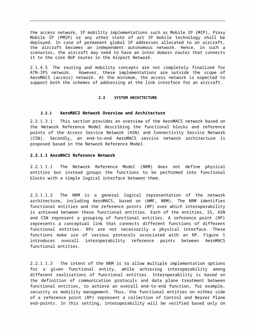
2.2.1.2.7 ASN Gateway Definition
2.2.1.2.7.1 As explained in 2.2.1.1.1, the ASN is not necessarily a physical entity but a functional block perfoming the following functions.
2.2.1.2.7.2 The ASN Gateway (ASN-GW) is a logical entity that represents an aggregation of Control Plane functional entities that are either paired with a corresponding function in the ASN (e.g. BS instance), a resident function in the CSN or a function in another ASN.
2.2.1.2.7.3 The ASN-GW is the main actor on the network topology, on which rely most of the management and control procedures to support the data link and its interconnection with the backbone. Moreover, the ASN-GW deals with interoperability between AeroMACS manufacturers as well. Figure 3 summarizes the functions attributable to the ASN-GW.
2.2.1.2.7.4 One single ASN-GW is expected to be deployed per airport domain. As depicted, the main interfaces for the ASN-GW are: the R6 reference point which connects it to the BSs and the R3 reference point which deals with the interconnection to the CSN.
Figure 3. Main Functionalities of AeroMACS ASN-GW
2.2.1.2.7.5 According to AeroMACS Network Architecture Reference Model, a generic ASN-GW covers the features/functionalities shown:
AeroMACS layer 2 (L2) connectivity with MS. Relay functionality for establishing IP connectivity between the MS and the CSN. Network discovery and selection of the AeroMACS subscriber’s preferred NSP. Subscriber IP address allocation by querying the DHCP server for network establishment and
DHCP DISCOVER messages forwarding.
1-18
IP forwarding to/from the backhaul via MIP Foreign Agent (FA). In case of supporting IPv6, the ASN-GW SHALL implement Access Router (AR) functionality. Note that this is a CSN function and does not necessarily have to be part of the ASN-GW functions, in which case it may deviate from the reference WiMAX Forum Profile C configuration.
Connection Admission Control to ensure service quality and different grades of service commitment and provision.
AAA proxy/client. AeroMACS ASN-GW SHALL trigger the exchange of susceptible subscriber information and transfer AAA messages of AeroMACS subscriber’s Visited NSP for authentication, authorization and accounting to the Home NSP.
Context management. Transfer of subscriber credentials (it can store user’s profiles or just cache them). Consequently, key distribution between entities.
User profile management. After the authorization phase and key exchange, the user profile is handled in order to create corresponding SFs.
Data Path establishment and Service Flow Authorization (SFA), CID mapping for control messages. GRE tunnelling SHALL be set to the BSs. ASN-GW creates one data path per SF. Every SF has each different GRE key value.
Mobility management and handover control.
2.2.1.2.7.6 An issue to address is how IP packets incoming from the backbone to AeroMACS are managed.
NOTE: This entity will then read the IP header, map it to an AeroMACS MAC QoS class and through means of GRE tunnelling, convey that packet to the specific BS to which the MS is attached.
2.2.1.2.7.7 AeroMACS ASN Profile
2.2.1.2.7.7.1 While the grouping and distribution of functions into physical devices within the ASN is an implementation choice, the AeroMACS architecture specification defines one ASN interoperability profile.2.2.1.2.7.7.2 A profile maps the ASN functions into the BS and ASN-GW so that protocols and messages, over the exposed reference point, are identified. The following text describes WiMAX Forum ASN Profile C based on the current (WMF, NWG)(WMF, NWG) Stage 2 specifications.
NOTE: The depiction of a function on either the ASN-GW or the BS in the figure below, does not imply that the function exists in all manifestations of this profile. Instead, it indicates that if the function existed in a manifestation it would reside on the entity shown. Identification of the ASN profiles was done for the specific goal of providing a framework for interoperability among entities inside an ASN.
2.2.1.2.7.7.4 According to Profile C, ASN functions are mapped into ASN-GW and BS as shown in Figure. Key attributes of Profile C are:
HO Control is in the Base Station. RRC is in the BS that would allow RRM within the BS. An “RRC Relay” is in the ASN GW, to relay
the RRM messages sent from BS to BS via R6. ASN Anchored mobility among BSs is achieved by utilizing R6 and R4 physical connections.

Figure3: WMF ASN Profile C
For more details refer to [2].
2.2.1.2.8 CSN Reference Network
2.2.1.3.3.8.1 CSN (Figure 4) is the network that provides end-to-end connectivity to AeroMACS subscribers with network entities and enables the provision of services by AeroMACS Application Service Providers (ASP). CSN main functionalities are AAA server and DHCP server. A CSN may be managed by a Home NSP, a Visited NSP or an ASP. The applicable RP are R3 (CSN with ASN) and R5 (between two CSN). CSN internal reference points are out of scope of this specification.

1-20
Figure 4: Detailed AeroMACS CSN Reference Model
2.2.1.2.9 AAA proxy/server
2.2.1.2.9.1 During logon aircraft credentials are presented to the AeroMACS CSN AAA server. AAA server verifies the credentials and checks the policy database in the context of aircraft before authorizing it. On approval from CSN, Aircraft logs into the Airport network and access Airport Services offered in the airports. Airport network also provides access to aviation internet for aircraft to avail services from remote ATCs and AOC centers.
2.2.1.2.9.3 While local users in an airport (e.g. handling vehicles) will be managed by a local airport AAA server via the ASN-GW, the most foreseeable scenario is one AAA proxy from the airport operator that sends queries and requests to a global database with all the aircraft operated by the H-NSP that will manage airborne user authentication and policy function (PF). AAA proxy covers the following functionalities:
Support roaming when required in case MS connects to V-NSP Simplify connection to several CSN Security capability that allows for logging in of MS locally (e.g. by an ANSP)
2.2.1.2.9.4 AAA servers deployed at each airport can be connected via a proxy network. This allows authentication of subscribers beyond the region of the service in the airport. However, the mechanisms to establish this proxy network are out of the scope of this document.
2.2.1.2.9.5 By default, the IETF RADIUS protocol is supported as the main protocol for AAA purposes. This is an application level protocol, client/server specifically.
2.2.1.2.9.7 Key Exchange using PKMv2 will rely on the fact that in AeroMACS user (subscriber) authentication is required. EAP-TLS framework is the defined suite to give support to user authentication. The aircraft router will use X509 certificates for EAP-TLS authentication, using as C/N (Common Name) realm, possibly the airline name (as network domains are currently defined by ICAO), or any PKI provider name. The H-NSP AAA server will receive authentication traffic with the username realm possibly being the airline – this means that the airport Proxy AAA will need to map the realm value with the H-NSP AAA address.
2.2.1.2.9.8 From the Access Service Network side, the ASN-GW acts as the end-point of the authentication communication flow. In case the ASN-GW hosts the user database, it plays the role of the

AeroMACS authenticator. In the case it doesn’t, it works as a relay, as an AAA client that forwards queries to the AAA server or the user data base.
2.2.1.2.9.9 AAA server is also in charge of checking the QoS policy for a given MS and consequently creating a Service Flow Authorization (SFA) as a response to a service flow initiation request from the MS.
2.2.1.2.9.10 AAA servers will depend on the core network managed by the Network Service Provider. AAA server databases could belong to the Visited Network of each airport; they could belong to the same virtual segment of network as AeroMACS or be held remotely in a different facility of the operator and therefore in another network (namely, the Home Network).
2.2.1.3.3.9.11 IPsec support for the transport of all connections is envisaged. Moreover, the use of VPN tunnelling is encouraged to secure all the connections to the remote elements of the backbone of the network.
2.2.1.2.10 DHCP server
2.2.1.2.10.1 The DHCP server resides in the CSN operated by the Visited or Home NSP. IP address assignment will be done after the MS has performed full network entry.
2.2.1.2.10.2 For the basic-connectivity IP service, the IP address is assigned by the CSN. For IP services accessible over an inner-tunnel, the network that terminates the tunnel allocates the IP addresses. Finally the IP allocation for surface vehicles can be done through a local IP pool in order to give dynamically IP addresses to them. See section on IP address configuration for detail.
2.2.1.3.4 AeroMACS Service Network
2.2.1.3.4.1 The Network Reference Model is valid to support the integration of AeroMACS datalink within the ATN/IPS backbone and give the corresponding service support. The overall principles followed to specify AeroMACS end-to-end network architecture are:
Functional decomposition: The proposed architecture allows that required features are decomposed into functional entities. The reference points are means to provide multivendor interoperability. For interoperability purposes, special care must be paid to the reference points R1 and R6 of the ASN reference model. Intra ASN mobility will imply full support of R6 control messages
Modularity and flexibility: The modularity of the proposed architecture gives the means to adapt to different AeroMACS deployments, and the interconnection to the ground infrastructure. As an example, the interconnection of different CSN topologies with just one single access network is permitted. The architecture also enables the scalability of the network in case after initial deployment the number of BSs installed within the airport needs to be increased in order to support more users.
Decoupling the access and connectivity services: This architecture enables full mobility with end-to-end QoS and security support, making the IP connectivity network independent from AeroMACS radio specification. In consequence, this allows for unbundling of access infrastructure from IP connectivity services.
Support to a variety of business models: AeroMACS architecture supports the sharing of different aviation business models. The architecture allows a logical separation between the network access provider (NAP), the entity that owns and/or operates the access network, the network service provider (NSP) and the application service providers (ASP). It is expected to

1-22
have just one single ASN-GW deployed in the airport domain. While one ASN-GW is generally used, there may be implementations with more than one single ASN-GW in the ASN.
2.2.1.3.4.2 The reference points can represent a set of protocols to give control and provide management support on the bearer plane. On an overall hypothetical deployment, functional entities here depicted could be matched to more than one physical device. In a similar manner, most of the reference points are left open. The architecture does not preclude different vendor implementations based on different decompositions or combinations of functional entities as long as the exposed interfaces comply with the procedures and protocols specified by WiMAX Forum NWG for the relevant reference points.Figure 5 presents an example of a high-level functional architecture to support communication with ground vehicles (airport operation) and aircraft (ATC, AOC). In such a case, at the airport, in addition to AeroMACS specific systems (base stations and ASN gateway) AAA server and DHCP server need to be deployed to enable communication with airport vehicles. The airport operator network would thus act as home network for airport vehicles.
2.2.1.3.4.3 For ATC and AOC service provision, the airport network would act as visited network, the home network being implemented at regional or global scale for aircraft. The Airport AAA server would thus act as an AAA proxy for aircraft relaying authentication and authorization requests from the ASN gateway to the Mobility Service Provider (MSP). The MSP is the administrative authority that can operate one or more Home Agents (HA) and usually corresponds to the Home Network Service Provider (H-NSP). Regarding IP connectivity, it is possible that IP addresses will be assigned directly by an H-NSP entity such as the AAA server or a global DHCP. However, the most likely case is that an IP address will be assigned locally to the MS and, in the case of an aircraft with a permanent home address, it will be announced to the network. The ASN gateway would also relay DHCP request to the Aircraft Home network DHCP server. For global connectivity and mobility support, the ASN will rely on a HA operated by an MSP.
Figure 5: AeroMACS network entities
2.2.1.3.5 Network Architecture
2.2.1.3.5.2 Definition of actors (H-NSP, V-NSP, NAP)
Figure 6 provides a logical representation of the overall networks at an airport.
Figure 6: Airport Network
2.2.1.3.5.3 The aviation internet (ATN/IPS) may comprise various networks with different administrative domains as explained below:
ANSP stands for Air Navigation Service Provider, the entity that manages the Flight Traffic in a region or in a country (Such as FAA or Eurocontrol). ANSP has its network deployed to support the air traffic applications as explained in Error: Reference source not found. ANSP networks belonging to various regions are interconnected to each other and thus providing a global network for datalink services.
Airport Network supports various Airport Services. Airport network may provide infrastructure for
Airport Service Providers to register and host their airport services in global or site-local domains. Site local services will be available within the airport network only, while global services will be available to anyone in the global Aviation internet. An example of a site-local application could be the real-time broadcast of surface vehicle position information. Such a real time information need not be broadcasted in the global domain.
AeroMACS network in the context of aircraft provides mobile connectivity to aircraft to access
airport network. It has the infrastructure to support dynamic connections, to handle subscriptions for mobile users and to ensure authenticity and privacy needed for aircraft’s safety communications. It corresponds to AeroMACS ASN and CSN network in the Reference Model. AeroMACS network may also offer other fixed link services for interconnecting various networks within airport domain.

1-24
ASP/Airline networks can be considered as private enterprise networks. An airport is expected to have multiple ASP networks. ASPs can host their servers / applications that are required to be accessed by external entities in the perimeter network (in a De-Militarized Zone (DMZ)), while the internal network elements can be kept inside the private LAN. For example, consider a weather service provider network at an airport. The network may comprise of sensors installed at various places of airport, servers to collect and process information from various sensors, routers, networking devices, personal computers for staff, internal mail servers etc., placed in the LAN side of the network, while the dispatch server that provides consolidated weather information to aircraft kept in the DMZ.
2.2.1.3.5.4 Airport network shall be connected to ANSP and Mobility Service Provider (MSP) networks using inter domain routing protocols so that it becomes a part of the aviation internet. Thus it offers global access to Airport Services, anywhere from aviation internet for supporting future air traffic management concepts. Aircraft connected to any part of ANSP network or MSP network should be able to reach airport network and access services offered at any airport through aviation internet.
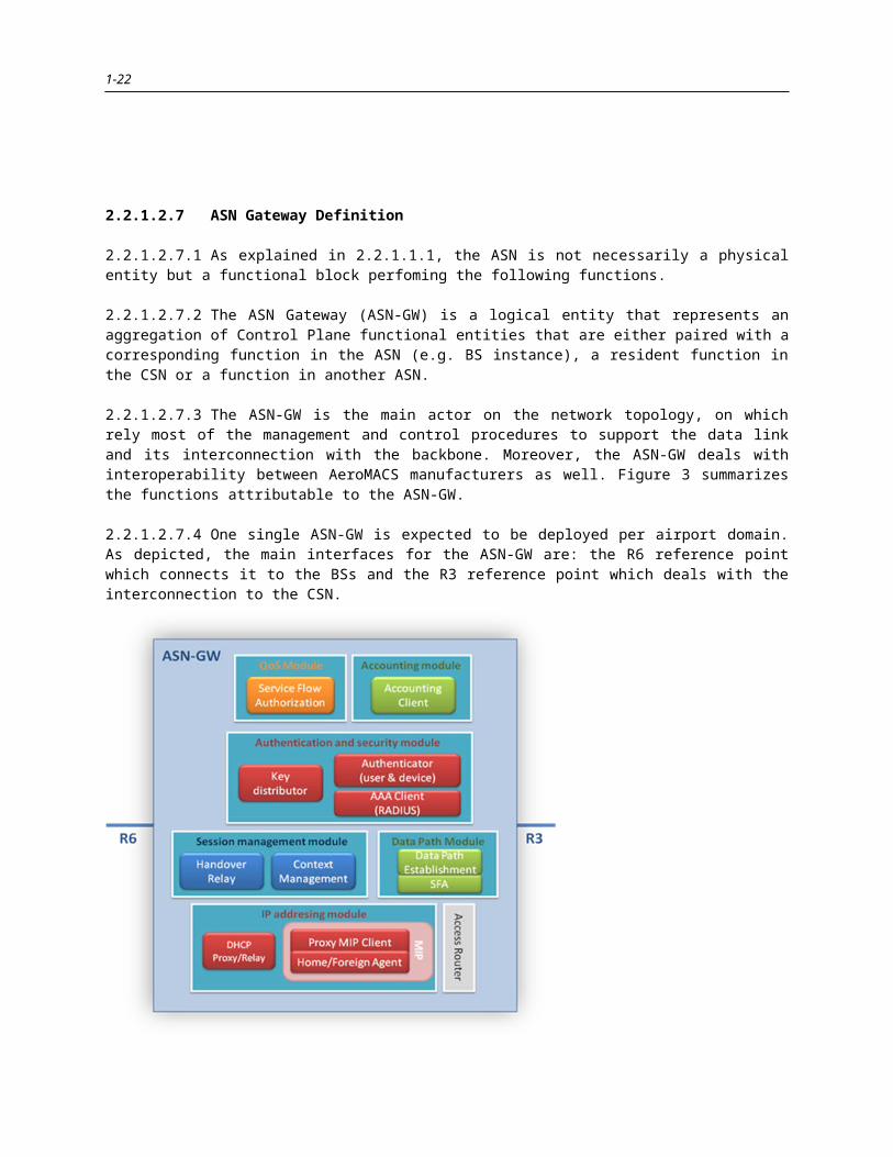
2.2.1.3.5.5 In order to access the services provided by the network, first an entity needs to provide connectivity to the subscriber. This is done by the provision of access service, IP configuration service, AAA service and mobility service (in the latter case the provider is called MSP). Aviation business models and contractual agreements between parties can have an impact on the network topology that supports AeroMACS service provision. Figure 7 depicts the overall contractual case and entities involved on behalf of provisioning services to the subscribers. AeroMACS architecture supports the discovery and selection of one or more accessible NSPs by a subscriber.
Figure 4: Overall relations between AeroMACS business entities [10]
2.2.1.3.5.6 The NAP is the entity that owns and operates the access network providing the radio access infrastructure to one or more NSPs. Similarly; the NSP is the entity that owns and provides the subscriber with IP connectivity and services by using the ASN infrastructure provided by one or more NAPs. An NSP can be attributed as a home NSP or a visited NSP from the subscriber’s point of view. A home NSP maintains service level agreements (SLA), authenticates, authorizes, and charges subscribers. A home NSP can settle roaming agreements with other NSPs, which are called visited NSPs and are responsible to provide some or all subscribed services to the roaming users. Within the aeronautical environment, the following actors could make use of AeroMACS business entities:
ANSP (Air Navigation Service Provider) as the owner and operator of the national navigation service network.
Airport authorities may offer AeroMACS services to aircraft. The subscription may offer a combination of network access and airport services provided by that airport authority.

Airlines may have their dedicated AeroMACS service for their aircraft exclusively. Large airline may even have their own AeroMACS infrastructure deployed at airports to service their aircraft.
ACSP (Aeronautical Communication Service Provider) e.g. AVICOM, SITA, ARINC, ADCC may offer AeroMACS services as part of their overall datalink service offerings. ACSPs can own AeroMACS networks extending their service at airports.
New/other global CSP (Communication - Mobility Service Providers). An independent service provider may offer AeroMACS service at an airport providing connectivity to aviation internet.
A summary of NAP/V-NSP/H-NSP services and possible actors is depicted in Table 1 below.
Table 1: Possible actors for NAP/V-NSP/H-NSP functions
Airport authority ANSP ACSP CSP AirlineNAP X x x xV-NSP X x x x xH-NSP x (for vehicles) x x x x
2.2.1.3.6 NSP & NAP deployment models
2.2.1.3.6.1 This section describes the foreseen deployments of NSP and NAP in an AeroMACS network. The models affect the number of possible NSPs and NAPs serving a given airport (one or several) and the role of the potential AeroMACS service providers.
2.2.1.3.6.2 NAP sharing by multiple NSP
2.2.1.3.6.2.1 This deployment model for mobile services in aircraft and vehicles proposes the existence of one Access Service Network per airport (owned and/or operated by a single entity) shared by multiple NSPs over a single NAP. It is also the most cost-effective solution to have both ATC and AOC services in the aircraft (using a single antenna and MS), and is in line with future ATN/IPS ground/airborne architecture supporting traffic segregation. AeroMACS allows the existence of multiple Network Service Providers for a given airport, and there is a defined method for the selection of the NSP by a given MS upon Network Entry.
2.2.1.3.6.2.2 This deployment model is the preferred solution by NSP and NAP in order to rationalize infrastructure, ease cell planning at a given airport, and minimize interference on legacy systems (e.g. Globalstar) with probably less Base Stations due to a more efficient use of the spectrum.
Figure 8: Single NAP - Multiple NSP
2.2.1.3.6.2.3 Several CSNs might share the same ASN. The most common deployment expected is one single ASN within the airport and multiple operators (CSNs) connected.

1-26
2.2.1.3.6.2.4 The NAP deploys and provides the access network to ARINC, SITA, AVICOM, etc. and manages the relationship with airports on behalf of the airlines. Airlines could act as H-NSP or have contractual agreements with different H-NSP.
2.2.1.3.6.2.5 In this scenario, the ASN-GW will advertise for incoming new MSs on the Access Network that there are different NSPs (see section Error: Reference source not found), enabling the MS to establish data communication to its NSPs through AeroMACS ASN and relaying them to reach the final airline operator.
2.2.1.3.6.3 Single NSP Providing Access through Multiple NAPs
2.2.1.3.6.3.1 This deployment model is foreseen by NSP to extend its coverage at regional scale in relying on local NAP (e.g. extension to several airports by one service provider like SITA or ARINC).
H-NSP
NAP i NAP j
Figure 9: Multiple NAP - Single NSP
2.2.1.3.6.3.2 If one NAP cannot provide full coverage for an NSP in a given area, the NSP can have agreements with multiple NAPs. This model is compatible with the previous one, i.e. multiple NAPs can be serviced by multiple NSPs and vice-versa.
2.2.1.3.6.3.3 There is a difference within this model depending on whether the NAPs served by a single NSP are collocated in the same airport or not. In the first case, the deployment option of placing the sensitive servers needed (mainly AAA and DHCP) locally would be possible, and there would be no need to enable VPN end-to-end connectivity, packet forwarding or relay functions, thus simplifying the rollout and operation of the network. In the latter case, connectivity to the global network would be necessary.
2.2.1.3.6.4 Greenfield NAP+NSP
2.2.1.3.6.4.1 This deployment model is foreseen for manufacturers and operator since they leave the flexibility to the NSP to act or not as NAP, depending on local issues.
2.2.1.3.6.4.2 This model is more suitable to CSPs, ACSPs or airlines in areas where they will be allowed to act as NAP. A single NSP, corresponding to the same CSP or ACSP, operates the network.

H-NSP
NAP
R3
H-NSP
NAP
R3
NAP + Home NSP
Figure 10: Greenfield NAP-NSP
2.2.1.3.6.4.3 Therefore ACSPs or airlines could be deploying themselves on the airport ground network side acting as the same entity for the NAP and NSP on the business model. An aircraft coming from a different airport will be served by the same H-NSP.2.2.1.3.6.4.4 In a number of regions, the AeroMACS license will be acquired by the Aviation Authority and may be granted to ANSPs directly or to Airport telecom entity or subcontracted for operation to a service provider. In other regions, service providers such as ARINC and SITA could be granted a specific AeroMACS channel for AOC and ATC operations. The most likely deployment scenarios are illustrated in Table 2.
Table 2: Potential AeroMACS deployment scenarios
Use Case N°
Description Subscriber NAP V-NSP H-NSP Deployment model
1 Local services
FixedVehicle
Airport telcoANSPACSP
Airport telcoANSPACSP/CSP
Airport telcoANSPACSP/CSP
Greenfield NAP+NSP
2 Safety and non-safety services on same channels
FixedVehicleAirline A/C
Airport telcoANSPACSP
Airport telcoANSPACSP/CSP
Airport telco (vehicle/fixed)ANSPACSP/CSP
NAP sharing by multiple NSPsOne NSP providing access through multiple NAPs
3 Safety services on specific channels
FixedVehicleAirline A/C
Airport telcoANSPACSP
Airport telcoANSPACSP/CSP
Airport telco (vehicle/fixed)ANSPACSP/CSP
NAP sharing by multiple NSPsOne NSP providing access through multiple NAPs
Non-safety services on specific channels
VehicleAirline A/C
Airport telcoACSPAirline
Airport telcoACSP/CSPAirline
Airport telco (vehicle)ACSP/CSPAirline
4 Non-safety services in airline hub
VehicleAirline A/C
Airport telcoACSPAirline
ACSP/CSPAirline
ACSP/CSPAirline
One NSP providing access through multiple NAPsGreenfield

1-28
Use Case N°
Description Subscriber NAP V-NSP H-NSP Deployment model
NAP+NSP
5 Safety services managed by ANSP
FixedVehicleAirline A/C
ANSP ANSP ANSP One NSP providing access through multiple NAPsGreenfield NAP+NSP
Table 2
2.2.1.3.6.4.5 Each deployment scenario, and specifically the role of the H-NSP, has an impact on the AAA framework, the subscriber management and the route optimization.
2.2.1.3.6.4.6 If the H-NSP is the airport authority (or an airport telco operator), performing these local functions in the local airport is straightforward. It also allows quick and secure access to local safety services without the need of a VPN since it does not use the ground network infrastructure. However, it does not make sense to establish connectivity with aircraft that are present at other airports. Hence, the assignment of H-NSP to the airport authority is suited to provide service to local equipment (sensors, handling vehicles, etc.).
2.2.1.3.6.4.7 If the H-NSP is the ANSP, it can provide a nation-wide mobility anchor point and IP address pool for aircraft flying in the domestic airspace. Being the network operator, it can manage the safety and performance requirements of the ATC services provided. ANSP could either own the access network at some or all of the nation’s airports (Greenfield model) or contract the use of the airport access network, which will act as a Visited NSP under a roaming agreement. The AAA proxy from the airport operator would send queries and requests to a database with all the aircraft operated by the ANSP that will manage airborne user authentication and policy function (PF). Airline services can be provided to contracting airlines under network leasing or SLA agreements. It becomes more challenging when a domestic aircraft flies to foreign airspace, since a roaming agreement needs to exist with the Visited NSP that manages the aircraft connectivity in the foreign airport. In addition, routing optimization should be used in this case in order to avoid data access between the aircraft and ASPs to be routed through the HA belonging to the ANSP since it could introduce high latency.
2.2.1.3.6.4.8 If the H-NSP is the airline, it may operate a global infrastructure of AOC centres providing airline services around the world regions that the airline covers. In such a situation, the airline may set up a global HAHA system in which the route for data access is optimized using the regional HA in each case. As in the case of the ANSP, the access network would be relied on local airport authorities or telco operators acting as V-NSP. For certain applications (e.g. maintenance), the airline could own an AeroMACS access network and set up a Greenfield deployment model. The issue with this model is that the airline may not be trusted by national ANSPs to manage the provision of ATC services under acceptable SLA safety and performance conditions. Another issue may be the high latency incurred in AAA exchange and data access in general, if a route optimization algorithm is not in place.
2.2.1.3.6.4.9 Finally, if the H-NSP is an ACSP, it can operate a global infrastructure facilitating the optimization of HA utilization depending on the location of the aircraft or other methods. The ACSP may own the AeroMACS access network in certain airports (Greenfield model) and use a third party infrastructure in others, as V-NSP. The AAA proxy from the airport operator would send queries and requests to a database with all the aircraft operated by the ANSP that will manage airborne user authentication and policy function (PF). ACSP can sign SLAs with the corresponding ANSPs, airlines and other ASPs for the provision of their services under certain safety and performance levels. The challenge with this approach is the large amount and complexity of agreements that the ACSP needs to sign with each ASP. Another issue may be the high latency incurred in AAA exchange and data access in general, if a route optimization algorithm is not in place.

2.2.1.3.6.5 Network entry and NAP/NSP selection
Several considerations on the NAP and NSP selection by the MS are given in this section, based on the permitted profile items, WiMAX Forum specifications and deployment models from Error: Referencesource not found. Manual or automatic selection is left as an open issue.
2.2.1.3.6.5.1 Overview of network entry
An aircraft MS network entry process is as follows:
During the scanning process the aircraft needs to be able to determine if it is on a channel of a NAP providing aircraft communication services.
If the NAP is providing aircraft communication services, the aircraft can either check that its H-NSP is connected or decide to authenticate directly
If the authentication is successful, it means that the NAP/V-NSP is able to contact the H-NSP.
Then the MS can perform NET entry and be allocated a CoA (Care Of Address). MS establishes MIP tunnel to the H-NSP Home Agent MS can then be contacted using its Home IP address through the Home Agent on the H-NSP.
In the case of an airport handling vehicle, the node is attached to the local network, and thus the network entry process is largely simplified:
During the scanning process the device needs to be able to determine if it is on a channel of a NAP providing airport services.
The H-NSP is based locally so the device can perform authentication directly. If authentication is successful, the MS performs NET entry and the H-NSP grants the device a
local IP address.
2.2.1.3.6.6 AeroMACS Discovery Procedures
2.2.1.3.6.6.1 AeroMACS profile allows two discovery procedures:
a. NAP discovery gives means to the MS, after scanning and decoding the “operator ID” element for DL_MAP, to select which BS of a particular operator to connect to. This is a very unlikely scenario since the deployment of several AeroMACS access networks will lead to increase the interference to non-AeroMACS systems.
b. NSP discovery is mandatory in the profile. The MS will dynamically discover all NSPs in the airport during the Network entry procedure. In order to accomplish that, the MS will be listening to the broadcast message with the NSP IDs sent by the BSs (SII-ADV MAC message advertisement). Therefore:

1-30
2.2.1.3.7 Roaming scenarios
2.2.1.3.7.1 Roaming is the capability of wireless networks via which a wireless subscriber obtains network services using a “visited network” operator’s coverage area. At the most basic level, roaming typically requires the ability to reuse authentication credentials provided/provisioned by the home operator in the visited network, successful user/MS authentication by the home operator, and a mechanism for billing reconciliation and optionally access to services available over the Internet services.
2.2.1.3.7.2 In a possible roaming scenario, an aircraft landing on an airport network is managed by an NSP that is different from the aircraft Home NSP (H-NSP), and thus acting as a Visited NSP (V-NSP). Figure shows the entities participating in roaming.
Figure 11: AeroMACS roaming architecture
2.2.1.3.7.6 The second foreseeable scenario is the use of one single AAA server, shared by all the NAPs and outside the H-NSPs. As a consequence, no roaming scenario will occur, whereas the risk of

failure and the probability of not completing the network entry and the creation of the data path increase. This has been covered within Error: Reference source not found.
<Editor’s note: The next section is related to network architecture but may be also relevant to Section 3.9 Routing and discovery. To be discussed in WGS>
2.2.1.3.7.7 Route Optimization Scenarios
2.2.1.3.7.7.1 Upon network entry, an MS selects an NSP that manages the connectivity of the subscriber to the network. In order to be able to access services from Application Service Providers (ASP) present in other networks different to the CSN managed by the NSP, data access needs to be established between the corresponding communication endpoints. Different mechanisms may be used for data access between communication endpoints that reside in networks managed by different NSPs, as depicted in Figure 12 and Figure 13 Error: Reference source not found. Note that, in order to show different attachment examples in the figures, configuration 1 aircraft is attached to the home network (which is a global network managed by an ACSP or other), while configuration 2 aircraft is attached to a visited network (e.g. a local ACSP in an airport or an ANSP network) through roaming. The following scenarios are deemed relevant for aviation purposes:
Data access via home NSP: This is the classic deployment where the H-NSP manages the HA function which establishes the paths between the Mobile Router (MR) behind the MS on the aircraft and the correspondent nodes (CN) in the ATM ground network. As a consequence, the application flow to the end node is relayed from/to the mobile node care-of-address in the foreign network to the HA and later to the CN. Optimized architecture NEMO (Global HAHA), shown in Figure , has been assessed both by NEWSKY Error: Reference source not found and SANDRA Error: Reference source not found projects.
Data access via correspondent router: This deployment model provides the opportunity to the mobile node to establish an optimized path directly with the correspondent router (CR). This leads to the benefit of optimising performance and having direct access to the CN and the ATM ground network (which can be located in the local access network), rather than having all traffic flowing to a central HA located in a remote location (shown in Figure 13).
Figure 12: Route optimization scenario 1 – Data access via Home NSP
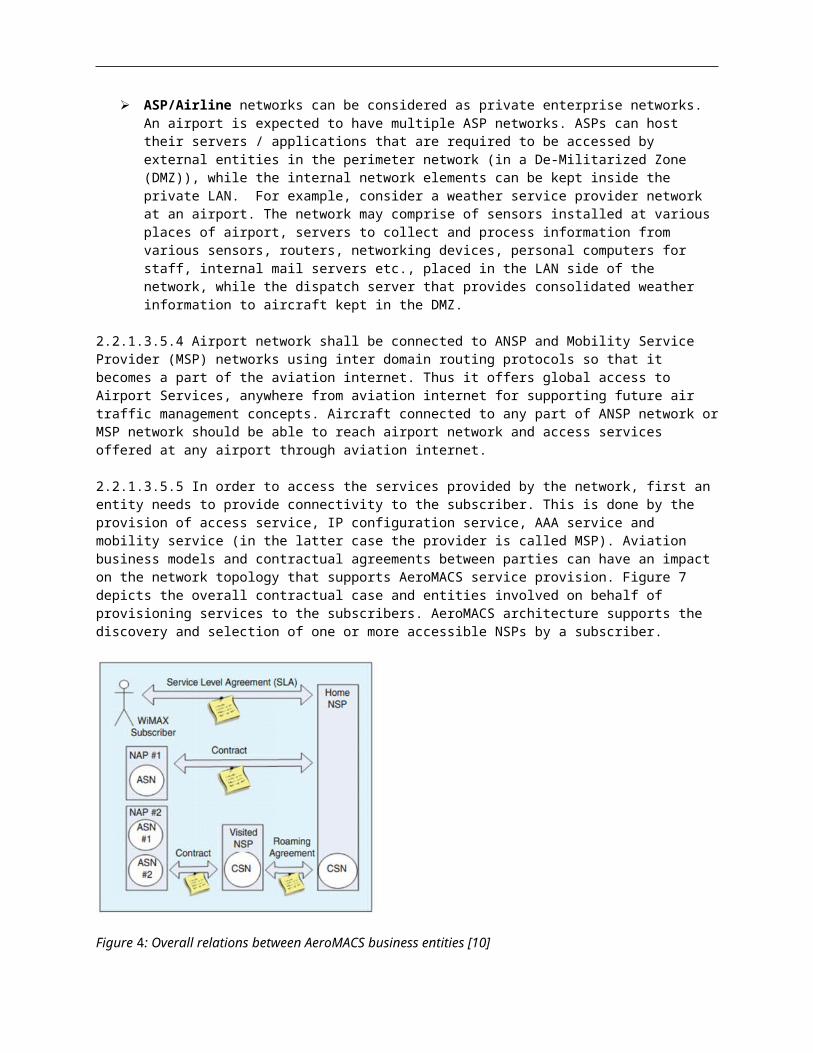
1-32
Figure 13: Route optimization scenario 2 – Data access via Correspondent Router (CR)
2.2.1.3.7.7.2 Several technical solutions are under definition to handle Route Optimization (RO with Mobile IP). One option is the Global HAHA (where local Home agents can be deployed as illustrated in Figure ), the other corresponds to the use of Correspondent Routers (CR) operated locally by ANSPs. In all cases, a global home agent must be accessible permanently.
2.2.1.3.7.7.3 SANDRA project concluded that the use of CR versus global HAHA was more appropriate to ATM communications.
2.2.1.3.8 Application Service Provider (ASP) Deployment Models
2.2.1.3.8.1 In an airport, AeroMACS service may offer seamless connectivity for aircraft to access Airport Network and its services, ANSP network (FAA, Eurocontrol or any other entity), as well as Airline or Service Partner Operational Centers to access datalink applications. AeroMACS may also be used to extend private networks that are owned by different Airport Service Providers within Airport premises or to interconnect networks within airport regions. Figure 14 provides the overall context of AeroMACS network at the Airport.

Figure 14: AeroMACS Network from Overall Perspective
2.2.1.3.8.2 In such scenarios, AAA should be able to appropriately distinguish aircraft (aviation internet) users from the other users and authorize them accordingly. This can be accomplished by using different profiles of digital certificates for different users. The ASN network shall have mechanisms to allocate IP addresses from different network domains accordingly.
2.2.1.3.8.3 In case if AeroMACS networks is deployed to support both aircraft traffic and other private network traffic, AeroMACS ASN network should be able to identify and route the traffic belonging to different networks respectively. Hence ASN becomes a highly sensitive component from aircraft security perspective.
Figure 15 shows various traffic through AeroMACS network, when it is deployed to interface with multiple networks.
1-34
Figure 15: Various Traffic Through AeroMACS
2.2.1.3.8.4 In the above figure,
Aircraft uses AeroMACS to connect to aviation internet Weather service provider uses AeroMACS as a point to point link to connect a weather sensor to
his network. SMGCS uses AeroMACS to contact vehicles in airport.
2.2.1.3.8.5 In this scenario, the ASN handles traffic from all the three independent networks; hence it becomes a common medium to transport packets for multiple networks. Therefore considering aviation safety internet, its security perimeter is limited to the airport network gateway as ASN handles multiple network traffic. To mitigate such risks, this paper recommends a secured pipe to be extended from aircraft edge router to airport network gateway, when an AeroMACS ASN infrastructure is shared with multiple networks, other private networks may also choose to have their own security mechanisms over shared AeroMACS network to safeguard their network traffic.
2.2.1.3.8.6 Deployment scenarios
2.2.1.3.8.6.1 The deployment scenarios of AeroMACS network are analyzed in this section. Figure 16 shows the scenarios of AeroMACS services offered through a dedicated network and also a shared network. In Figure 16, JKF airport has a dedicated ASN infrastructure installed by the NSP/MSP exclusively for aircraft connectivity. At CDG airport, the MSP uses a shared AeroMACS network provided by a third party network access provider (NAP). Assume that the local service provider uses AeroMACS network for offering both aviation internet service as well as local network connectivity services (shared network).

2.2.1.3.8.6.2 At JFK airport, the AeroMACS network is exclusively deployed for MSP subscribers. Both the ASN and CSN networks belong to MSP. Hence, the CSN AAA server (belonging MSP) acts as the final authenticator, approving aircraft to log into the AeroMACS ASN network. During logon digital certificates are exchanged between the AAA server (under MSP administrative network) and aircraft for mutual authentication. A common Certification Authority should have either signed the certificates of the AAA server and the aircraft or should be available in the trusted path of the Certificate Authorities to establish the authenticity of the entities. On successful verification, the data connections are established with aircraft at ASN. ASN Gateway is connected to MSP Gateway which offers connectivity to aviation internet. Aircraft shall access ANSP services or Airport services through Aviation internet as shown in the figure. In this configuration the ASN is exclusively used for aircraft communications and hence the safety network boundary extends up to aircraft. Therefore no additional precautions other than the AeroMACS inherent security over wireless interface are required for the network deployment.
Figure 16: AeroMACS offered by NSP/MSP
2.2.1.3.8.6.3 At CDG airport, the ASN / CSN infrastructure are deployed by a third party service provider. When an aircraft, having MSP subscription, tries to log into network, the CSN (belonging to a third party local network) will not have MSP subscriber account details. Hence, in this case, the AAA server at the CSN network will act as a proxy and contact AAA server at MSP network to authenticate the aircraft. Aircraft shall use WiMAX AVP, Operator Name, to indicate its preferred Network Operator. As a prerequisite, MSP and the particular airport network service provider would have a prior business agreement and the AAA servers are connected to handle this back end authentication. On approval from the MSP AAA server, access to the airport network/aviation internet is granted to the aircraft. In this scenario as the Airport network ASN is shared across multiple networks, the security boundary for the aviation internet can be considered only up to the Airport Network Gateway as ASN handles multiple network traffic. Hence to ensure security a VPN connection is established between aircraft edge router to

1-36
the Airport Network Gateway to transport packets safely through ASN network. Message Flows between various network elements in AeroMACS network is provided in Figure 17.
Figure 17: Message Flows in AeroMACS Network
2.2.1.3.9 Mobility
<editor’note: Need to re-discuss the requirement to implement MIPv6 in the light of the WGI discussions>
2.2.1.3.9.2 Currently the ATN/IPS 9896 is identifying the Mobile IPv6 as the mechanism to provide global mobility among access networks in the ATN network. ATN/IPS requires the use of bidirectional tunnelling, i.e. routing packets from source to destination through the HA in both directions, which may lead to suboptimal routes. Although the ATN/IPS Manual recommends the use of IPv6 route optimization under RFC3775 and RFC4651, it acknowledges the potential for enhancements to Mobile IPv6 such as:
HMIPv6 FMIPv6 PMIPv6 NEMO
2.2.1.3.9.3. The various mobility options are under evaluation in ICAO and other group and changes maybe agreed to the ICAO recommended approach for mobility.
2.2.1.3.9.4 It is foreseen that global IPv6 addresses will be assigned to specific aircraft or on-board data link equipment such as AeroMACS. This can be done via static IP addresses or dynamically via Mobile IP mechanisms. The support of dynamic IP addresses allocation (DHCP) and roaming for aircraft needs the support of global IP mobility and contractual agreements between NSPs or NAPs in order to allow the global identification and operation of airborne devices. Subscriber and Home Agents (HA)

implement Mobile IPv6 as specified in ICAO Doc 9896 Error: Reference source not found. According to [12], an ATN/IPS MSPs operates one or more Home Agents.
2.2.1.3.9.7 The redirection of an incoming packet to the home network from the visited network where the aircraft is currently in is done through a tunnel established between HA and FA or AR.
2.2.1.3.9.9 HA location could vary in a real scenario and can be centralized or decentralized. On the opposite, AAA is expected to act as a proxy only in the V-NSP. This foreseeable scenario is depicted in Figure 18.
Figure 18: AeroMACS AAA and HA Deployment Scenario
2.2.1.3.9.10 Several options for the location of the FA/AR are envisaged, namely:
a) physically inside the ASN-GW equipment (as in Profile C) and dedicated to mobility functions only for the MSs in the ASN,b) as a separate entity in the local airport network and dedicated to mobility functions only for the MSs in the ASN,c) as a separate entity in the local airport network and able to perform mobility functions for any node in the local network, including one or more AeroMACS ASN and other IP end nodes.
Note: The FA/AR will not, in any case, operate to provide IP connectivity and mobility functions to other data links other than AeroMACS.

1-38
2.2.1.3.10 IP address configuration
2.2.1.3.10.13 AeroMACS service provider may choose to have a centralized CSN managing multiple ASNs in different airports. In such scenarios,
2.2.1.3.10.15 Alternatively ASN gateway (acting as a DHCP proxy) shall contact Airport Network Gateway (which acts as DHCP Server) to get IP address for aircraft’s AeroMACS connection. This IP address is expected to be unique in the scope of global aviation internet. If the aviation internet (ATN/IPS) supports dynamic DNS service for aircraft, aircraft shall register its new IP address with the DNS services.
2.2.1.3.10.16 Following the network entry procedure, an AeroMACS MS can reach the connection establishment state and belong to a broadcast domain (layer 2), thereby getting access to network elements beyond the BS which at data plane level is just bridging air and wireline media. Therefore, once layer 2 is granted, the question on who is listening to the MS broadcast messages to obtain an IP comes up. The forthcoming procedures depend on the type of IP version convergence sub-layer established in the previous phases.
2.2.1.3.10.17 For IPv6, from the AeroMACS MS perspective the first hop router is the access router in the ASN-GW.
Core Router
IPv6 Access Router
MS
ASN CSN
External network (service
s)
Figure 19: AeroMACS IPv6 Data Connectivity Network Elements
2.2.1.3.10.18 The MS performs initial network entry to activate the Initial Service Flows. The establishment of the IPv6 Initial Services Flows enables the sending and receiving of IPv6 packets between the MS and the access router. Then router advertisement and address assignment procedures are initiated.
2.2.1.3.10.19 The information contained in the router advertisement message is learnt by the ASN from the attributes present in the RADIUS (or DIAMETER) authentication accept message sent by the authentication server during the network authentication phase. That content will depend on the network operator access policies.
2.2.1.3.10.20 Then, the ASN shall advertise an IPv6 prefix from a preconfigured pool of prefixes belonging to the directly attached CSN. In case of NAP sharing, the ASN may have several different prefix pools associated with different CSN. In such case the ASN shall use the realm part of the Network Address Identifier (NAI) to select an appropriate pool to set in the IPv6 Router Advertisement messages to send to the incoming MS [5].
2.2.1.3.10.21 The message sequence chart in Figure 20 describes the sequence of protocol messages exchanged between the MS and the network during the IP address allocation phase.

Visited NSP Home NSP
AeroMACS NAP
MS BS Core
Router AAA Access Router
IPv6 Router Advertisement
L-3 Path Established (User traffic)
L-2 Link Established
L-3 Path Established
Accept: “IPv6 prefix information”
MS performs network address auto configuration
Figure 20: AeroMACS IPv6 Data Connectivity Establishment Message Sequence Chart
2.2.1.3.10.22 After the layer 3 path is established the following diagram model is in place for a typical deployment scenario:
AeroMACS NAP
MS BS
Access router
BS
MS L-3 link
L-3 link
L-3 link
Operations
DHCP server
DNS server
L-3 link
External Networks
L-3 link
Other services
Core Router
NSP
Figure 21: AeroMACS Data Plane Typical Deployment
2.2.1.3.10.23 All operations services are layer 3 reachable by the MS. This model supports the extension to any service such as IMS, SNMP management, TFTP configuration server, subscriber/policy management, etc. The external networks can be any of these: other service provider (NSP), a corporate VPN (airline network), aeronautical Internet or any other application partner.

1-40
2.2.1.3.10.24 Obtaining IP address, access to layer 7 applications, roaming, implementation of management system and so on can be implemented in AeroMACS by following (but not limited to) the solution described in this section.
2.2.2 Avionics Architecture

2.3 Security
2.3.1 IEEE 802.16 Security Profile
Figure 0-5 WiMAX Security Sub Layer (Source: IEEE 802.16 standards)
2.3.1.1. The security sub layer provides subscribers with authentication and data privacy. Authorization/SA module is responsible for validating the authenticity of Subscriber Stations and management of Security Associations (SA) for WiMAX connections.
2.3.1.2 SA associates encryption keys and algorithms with a traffic type, so that the packets belonging to a particular traffic type can be encrypted as per its SA definitions.
2.3.1.3 WiMAX supports two methods of authentications namely, RSA based authentication and EAP Based authentication.
RSA authentication method uses X.509 digital certificates and RSA encryption algorithm along with RSA keys, associated with the MAC address of a subscriber station. In this method, a base station authenticates subscriber stations, but the other way is not possible as mutual authentication is not supported in RSA scheme.
EAP method offers mutual authentication in which both BS and SS authenticate each other. EAP supports multiple authentication schemes and hence provides more flexibility to the network operators in choosing subscriber authentication methods. For example, EAP-TLS is based on X.509 certificates, while EAP-SIM is based on Subscriber Identity Module used in mobile phones. EAP method definitions are kept outside the scope of WiMAX standards.
2.3.1.4 PKM protocol is responsible for deriving and managing the keys used by WiMAX layer. WiMAX supports two versions of PKM protocol namely, PKM 1 and PKM 2. PKM 1 works in conjunction with RSA scheme to authenticate a subscriber and derive keys for SS, while PKM2 supports EAP method for mutual authentication of both SS and BS and their key management.

1-2
2.3.1.5 In addition to PKM2 in a typical deployment environment involving large networks, authentication and policy management for subscribers would be done at centralized locations instead of being managed locally at every BS level. In such scenarios, RADIUS protocol may be used in conjunction with EAP methods to authenticate/authorize subscribers to use network resources.
2.3.1.6 The traffic encryption module supports a set of encryption algorithms to protect the message data. Depending upon the definitions in SA, this module performs encryption/decryption of the data that enters or leave the WiMAX device.
2.3.2 Security Sub-Layer for AeroMACS (Layer 2)
2.3.2.1 This section contains the definitions of layer 2 Security Sub layer down-selected from WiMAX (IEEE 802.16 ) profile specifications. Error: Reference source not found provides the overall stack architecture of Security Layers across various network components such as SS, BS, ASN G/W and AAA servers.

Figure 0-6 AeroMACS Security Sub Layer ( Layer 2)
Traffic Data encryption
Control Data Signing
PKM v2
SA control
EAP
TLS
Traffic Data encryption
Control Data Signing
PKM v2
SA control
EAP Transit
PHY PHY
802.16 MS 802.16 BS
RADIUS Client
UDP
IP
WAN I/F
ASN G/W
RADIUS Proxy
UDP
IP
WAN Interface
Proxy
TCP/IP NW
AeroMACS AAANAP
RADIUS Server
IP
WAN Interface
EAP
TLS
AAA Server
Application NW AAA
UDP
R6

2.3.2.2. The protocol options recommended for the AeroMACS network are,
PKM V2 for Public Key Management EAP for Authentication TLS method to be used along with EAP for exchanging Authentication parameters.
The rationale for the selection is explained in the further sections.
2.3.3 Key Management
2.8.3.1 As explained in section Error: Reference source not found, WiMAX standard supports two options for Key Management namely, PKM V1 and PKM V2 protocols. PKM V1 supports single-side authentication in which only SS gets authenticated by BS and BS is not authenticated by SS. On the other hand, PKM V2 supports mutual authentication where both SS and BS authenticate each other. Moreover PKM V1 does not support EAP authentication protocol. This means a centralized authentication framework for AeroMACS is not possible with PKM 1 protocol. PKMv2 is designed to support EAP protocol with an extendable back end RADIUS support. RADIUS offers flexibility to support multi layered authentication with proxy extensions. As AeroMACS requires authentication from multiple networks, RADIUS support becomes mandatory for AeroMACS. Therefore, PKMV2 is recommended for AeroMACS to ensure higher security and easy network access manageability. 2.3.3.2 Authentication Protocol
2.3.3.2.1 Three Authentication protocols are available in PKM V2 framework as defined in the WiMAX specifications namely,
RSA authentication Extended Authentication Protocol (EAP) RSA and EAP authentication
2.3.3.2.2 RSA provides a fast unidirectional authentication mechanism where the BS authenticates the client using X.509 certificates. But RSA does not provide mutual authentication where MS also authenticates the BS. Hence the overall security offered by RSA is not as strong as compared to EAP.
2.3.3.2.3 EAP is a flexible authentication protocol that offers multiple authentication methods which are explained in the subsequent section. It offers mechanisms for mutual authentication of BS and MS and can be used along with PKM v2 protocol.
2.3.3.2.3 RSA and EAP combined procedure starts with RSA mechanism for authenticating client and then followed by EAP mechanism for authenticating BS with MS. In our opinion this option does not offer any great advantage over the single stage EAP TLS process where mutual authentication can be done based on X.509 certificates of BS and MS. Moreover this two stage process would consume more negotiation time and require more message transactions compared to EAP method.
2.3.3.2.4 Hence EAP protocol is recommended for the AeroMACS application.
2.3.3.3. EAP Authentication Methods
2.3.3.3.1 The WiMAX standard does not recommend any specific (or set of) EAP method(s) for the deployment. Hence the following set of commonly used mechanisms that provide strong authentication are considered for analysis
EAP SIM : is based on SIM card mainly developed for authentication in 2G network. It requires a separate SIM module for authentication.
EAP AKA: is also a SIM card based authentication scheme used in 3G networks. EAP TLS : Offers strong authentication based on X.509 certificates exchanged between
authenticator and the mobile station. This is widely deployed in the WiMAX networks. EAP TTLS/MSCHAP: TTLS offers two stage authentication mechanism in which Server is

1-2
authenticated first using TLS procedures and then secured client authentication happens using any of the authentication schemes like user password, MSCHAP,PAP, TLS etc., During 2nd stage, a secured tunnel is established between the authenticator and MS, thus securing user credentials transferred in public wireless medium. This method has an advantage over TLS in cases where client certificates can be eliminated. But, in case of AeroMACS considering multiple networks and AAA servers, maintaining client credentials in all AAA servers and refreshing them periodically using secured mechanisms whenever the credentials change. Hence in AeroMACS scenario, TTLS does not offer any advantage, but may consume more time in authentication as it has 2 stage authentication processes.
2.3.3.3.2 Hence EAP TLS method is recommended for AeroMACS application.
2.4 Support for Broadcast and Multicast Applications in AeroMACS.
2.4.1 Introduction
2.4.1.1 This section provides guidance material on how AeroMACS system is supporting broadcast and multicast applications today as well as how it can continue to support these applications, in an evolutionary way, and more efficient in the future when the supported traffic will be increasing.
2.4.1.2 In this section, the broadcast and multicast capability refers to functionalities that take advantage of the PMP (point to multipoint) operation of the AeroMACS link to use efficiently the radio resources by transmitting the same data payload from one BS to different MSs in a single multicast message (as opposed to transmitting the same infSUpormation to each MS in different unicast messages).
2.4.1.3 PMP operation (OSI layer 2) is independent from the operation of IP multicast and broadcast (OSI layer 3) or the execution of multicast and broadcast services (OSI layer 7).
Note 1: IP multicast and broadcast or MBS applications are not considered in this paper.
Note 2: Higher layer multicast services can be transported over unicast AeroMACS data links even if the PMP operation is not supported. In such a case, support for Broadcast and Multicast application is still feasible but without optimizing the radio resources.
2.4.1.4 It is highlighted that the AeroMACAS PMP operation applies only to BS to MSs messages and it does not apply to the MS to a BS direction. It is noted that the MS to BS transmissions are always unicast in AeroMACS as the MS transmissions are always towards the (master) BS.
2.4.2 Requirements for Muticast and solutions
2.4.2.1 The list below indicates the potential MBS services envisaged to be transported over AeroMACS [SESAR 15.2.7 D1.1 Profile Analysis]:
- Flight Information Services (D-ATIS, D-OTIS, D-RVR, D-SIG, D-SIGMET)
- TIS-B
- NOTAM
- Graphical weather information (WXGRAPH)
- Airport delay information
- Broadcast weather information via SWIM

- SURV
<Editors note: to Discuss in WGS, if the section on the multicast gain justifying the benefits of multicast is really needed. Suggest to consider accepting the need for multicast and to not provide the analysis of the gain below>
2.4.2.2 An estimation of the amount of data generated by specific services can be worked out from the analysis made in the service modelling list referenced within the AeroMACS MASPS Using the number of messages per dialogue and the size of these messages, together with the maximum service latency, the average data rate (in bps) can be derived in order to comply with the latency figure.
2.4.2.3 Based on this analysis, the estimated peak data load generated by the ATC multicast services operated by a single aircraft ranges from 1 to 9 kbps [SESAR 15.2.7 D2.2 Traffic Modeling]. On the other side, an AOC multicast service would be expected to transmit a heavier load of data. The only available example of a computation of the expected data rate generated by an AOC multicast service has been done with WXGRAPH [SESAR 15.2.7 D2.2 Traffic Modeling].
2.4.2.4 The table below depicts the required bandwidth at an airport operating AeroMACS considering the potential air operation scenarios as presented in the Draft AeroMACS MASPS. The table indicates the expected peak data rate (i.e. if all the present A/C operate the service simultaneously) per cell. It can be observed that an AeroMACS deployment can well cope with ATC multicast services. However, when multicast AOC services are also enabled, the benefit of operating multicast connections becomes relevant.
Operations/ hour per airport
Assumption of number of simultaneous A/C per airport
Assumption of number of BS (cells, i.e. sectors) deployed in airport
Assumption of number of MS in cell
Estimated peak traffic generated per cell by ATC multicast services [kbps]
Estimated peak traffic generated per cell by WXGRAPH [kbps]
Unicast Multi cast
Unicast
Multi cast
20 10 3 3.33 30 9 250 7550 25 9 2.78 25 208100 50 15 3.33 30 250
2.4.2.5 Considering the above analysis, the support by AeroMACS of the Multicast capability will provide the following gain to the overall AeroMACS system capacity:
Multicast Gain [kbps] =
(Multicast services estimated load [kbps]) * (Number of simultaneous MS in the same cell sector - 1)
Accordingly, the Multicast Gain in kbps and % relative to the DL worst case (QPSK1/2: 1.8 Mbps) and best case (64 QAM: 9.1 Mbps) can be estimated from the data in the table above:
Airport size
ATC multicast services [kbps] WXGRAPH [kbps]
Unicast MulticastGain
(kbps)Gain (%)
Unicast MulticastGain
(kbps)
Gain (%)
worst best worst best
20 30 9 21 1.16 0.23 250 75 175 9.72 1.92
50 25 16 1.44 0.17 208 133 7.42 1.47

1-4
Airport size
ATC multicast services [kbps] WXGRAPH [kbps]
Unicast MulticastGain
(kbps)Gain (%)
Unicast MulticastGain
(kbps)
Gain (%)
worst best worst best
100 30 21 1.16 0.23 250 175 9.72 1.92
2.4.3 Solutions for Multicast and Broadcast
2.4.3.1 The possible options to support multicast / broadcast according to the IEEE 802.16-2009 standard and the AeroMACS Profile and MOPS are shown in the Table below, which also describe the support of each option for security features. The best option depends on the type and volume of multicast / broadcast services (MBS) to be transported over the data link, and the level of security required for these services.
Multicast option Security on multicast connectionsYes No
No N/A UnicastMBS MBS with MBSGSA MBS with either:
“No authorization” policySA with “No encryption” cryptographic suite
Multicast group service Multicast traffic connection with GSA
Multicast traffic connection with either:“No authorization” policySA with “No encryption” cryptographic suite
2.4.4 Unicast
2.4.4.1 If this option is followed, all multicast and broadcast services are transmitted over unicast messages on the AeroMACS data link. The CID establishment, traffic classification and QoS rules for incoming traffic are applied the same way as the rest of the service flows.
2.4.4.2 This option requires no support of any additional item, nor any additional test case. The AeroMACS Profile “multicast transport connection” item may be set to N in this case.
2.4.4.3 This option is acceptable as far as the amount of traffic generated by the network due the transmission of MBS services is small. Note that this does not depend on the number of receiving MS, only on the service load, however the impact on the data transmitted over the radio grows multiplicatively with the number of MS in the cell.
2.4.5. MBS with MBSGSA2.4.5.1 MBS is an efficient method to concurrently transport DL data common to a group of MS (called multicast group). Service flows and multicast CIDs transmitting MBS flows are instantiated by a BS or group of BS (called a BS zone) and the registered MS belonging to the multicast group learn from them. The existence of BS zones allows for the provision of Macro Diversity. If a multicast CID is encrypted, it requires the establishment of a MBS group security association (MBSGSA) per multicast CID to maintain the MBS key material (MAK, MGTEK and MTK). MBSGSAs are shared between the BS in the same MBS zone.
2.4.5.1 This option requires the support of a large number of items such as MBS MAP IE and management of MBSGSA multicast keys. Since these items are currently not mandated by the

AeroMACS Profile, no test cases exist and they are not supported by current COTS products, this option is not recommended due to its high cost.
2.4.6 Multicast Traffic Connections2.4.6.1 Multicast Traffic Connections (MTC)is the recommended way to support broadcast and multicast in AeroMACS operations. This section distinguishes two types of MTC: MTC without encryption and MTC with encryption. These two optios are further described in the next two sub sections.
2.4.6.2 Multicast Traffic Connections without Encryption2.4.6.2.1 The BS establishes separately a transport connection with each MS in the multicast group by using the same CID. In this manner, the authorized MS will listen to the same channel in the DL frame and access the multicast/broadcast data payload. From the MS point of view, the CID is treated as a unicast connection. From the BS point of view, it is also treated as a unicast connection with the exception that classification rules need to be configured to transmit multicast messages over the common CID. Since each connection is associated with a service flow, it is associated with the QoS parameters of that service flow. ARQ is not applicable.
2.4.6.2.2 This solution can be followed by implementing an authorization policy (for the BS-MS pair) or a cryptographic suite (for the SA) not supporting security features.
2.4.6.2.3 Authorization policy is exchanged per BS and MS pair during network entry (or reentry). The MS informs the BS about the types of authorization policy supported during negotiation phase (SBC-REQ/RSP message exchange). Table 123 below from the WiMAX Forum Profile depicts the authorization policies supported by the AeroMACS Profile. If “No Authorization” is selected as the authorization policy, no key exchange, authentication or encryption is performed with this MS. Null SAID is used by default for all the connections.
2.4.6.2.4 This solution avoids the necessity to perform authorization and encryption but affects all the transport connections established with a given MS. Thus, it is not acceptable since it precludes unicast connections from being secured.
2.4.6.2.5 Cryptographic suites are the combinations of mechanisms for encryption, data authentication and TEK exchange, and are specific to SA. During the authorization exchange (except if “No Authorization” policy is chosen), the BS sends the MS a list of SA Descriptors informing about the cryptographic suites used by the static SAs that are active. During Dynamic Service Addition (DSA), SAID is mapped to a given SFID. Table 125 below from the WiMAX Forum Profile depicts the cryptographic suites supported by the AeroMACS Profile.
2.4.6.2.6 [IEEE Std 802.16-2009] does not preclude a BS-MS having different SA active, of which some use key exchange, encryption and data authentication, and some do not, if the BS is configured to support both types of static SA. Thus, it is recommended for the support of unsecure multicast connections that each BS configures a static CID well known to all MS participating in the multicast group. Upon network entry, the CID and associated SFID are established, and a corresponding SA supporting no security is activated and associated to this CID/SFID. Note that it must be a unicast SA, meaning that it is established independently with each MS. However, since the data is sent in plain, all the MS should be able to decode the received data.

1-6
2.4.6.2.7 This mechanism is compatible with HO optimization. When an MS performs handover, the target BS should already possess the security context of the multicast CIDs, so it does not need to perform MS reentry.
2.4.6.2.8 This is valid for services that do not require security at radio level and device authentication, such as weather reports, NOTAM and flight information services.
2.4.6.2.9 This option requires the support of “multicast traffic connection” item and the support of “No data encryption […] cryptographic suite”. It is NOT required to support “No authorization” policy. To make multicast function operate in every AeroMACS ASN, it is required that the allowed set of CID(s) is fixed globally.
2.4.6.2.10 Figure X?? below depicts the message exchange during a normal network entry involving the creation of secured unicast DL/UL traffic connections and unsecured multicast DL traffic connections. Note that the unsecured multicast CID3 needs to be the same for all the MS connected to the same BS, however the SAID is created independently per MS.

MS1 BS
DL channel acquisition, MAC synchronization (DL-MAP) and obtaining UL channel parameters
Initial Ranging and PHY adjustments process (RNG-REQ/RSP)
SBC-REQ (EAP based authorization)
SBC-RSP
EAP Request
EAP Success
EAP based authorization for unicast based communications being further secured
The MS gets authenticated in the network and the security context is created
PKMv2 (SA-TEK-Challenge)
PKMv2 (SA-TEK-Request)
PKMv2 (SA-TEK-Response / SAID1 = Crypto suite T125, I6SAID2 = Crypto suite T125, I1)
SAID1 = Primary SA to be used by secure unicast connectionsSAID2 = Static SA with cryptographic suite set to no encryption to be used by multicast connections
PKMv2 (Key-Request / SAID1)
PKMv2 (Key-Reply / SAID1)
MS acquires the valid TEK keys for SAID1
Registration
DL SF creation (Target SAID = SAID1, CID1)
UL SF creation (Target SAID = SAID1, CID2)
Establishment of secured (SAID1) unicast connections (CID1 and CID2)
DL SF creation (Target SAID = SAID2, CID3)Establishment of unsecured (SAID2) multicast connections (CID3)
MS2
Same procedure that MS1
DL SF creation (Target SAID = SAID3, CID4)
UL SF creation (Target SAID = SAID3, CID5)
DL SF creation (Target SAID = SAID4, CID3)
MS1 and MS2 shares unsecured CID3 multicast channel identifier
Figure X??: Establishment of encrypted unicast and unencrypted multicast connections in AeroMACS
2.4.6.2.11 This solution does not compromise PKMv2 authorization and authentication which is established when the MS enters the network. In addition, this solution does not impose???? encryption in
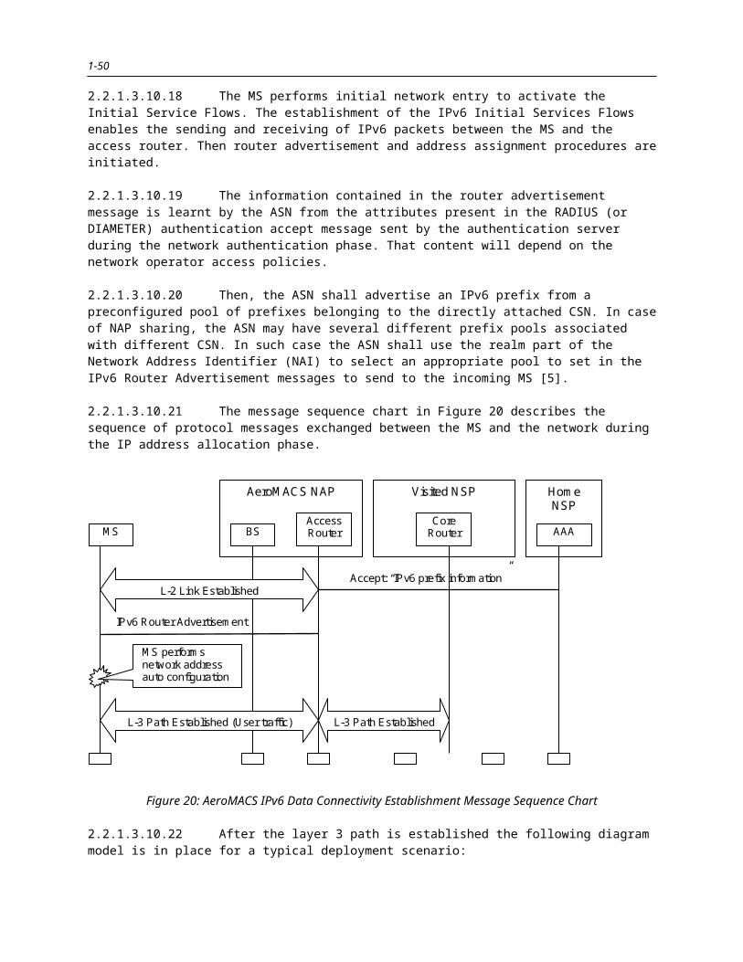
1-8
unicast services which is establish whenever the BS and MS initiates Services Flows linked to Security Associations with Encryption enabled.
2.4.6.3 Multicast Traffic Connections (MTC) with Encryption
2.4.6.3.1 MTC with encryption is the evolution of the solution proposed in the previous section aiming now to also support encrypted multicast and broadcast messages.
2.4.6.3.2 If the DL multicast connection is encrypted, it requires the use of a Group Security Association (GSA) to maintain group key information. During PKMv2 handshake, the GKEK is randomly generated once and distributed to the BSs via the ASN-GW (according to Profile C), and then transmitted to each MS encrypted with each corresponding KEK. The same GTEK is thus derived for all the MSs belonging to the multicast group and encrypted with the GKEK.
2.4.6.3.3 This option would be required if the majority of the MBS services to be transported over multicast connections need to support MAC security (in addition to already existing service and network security protocols). This could be the case of some flight information services such as TIS-B, or future SWIM services, but no requirement currently exists.
2.4.6.3.4 This option would require the support of “Multicast traffic connection” item and “Group multicast service SA” item, plus the development of corresponding test cases. For the sake of interoperability, it is required that the allowed set of CID(s) is fixed globally. This would need a requirement or guidance material (depending on the intended level of mandate) in the MOPS and ICAO SARPs or Technical Manual.
2.4.6.3.5 Functionality will need to be provisioned in the ASN-GW to distribute the group key GKEK to the BSs and also the GTEK context during HO procedure, in order to support HO optimization item “Skip TEK establishment phase”.
2.4.6.4 Encrypted unicast and unencrypted multicast coexistence:
2.4.6.4.1 According to the message exchange above encrypted unicast messages and unencrypted multicast messages can coexist for a given AeroMACS session. Encrypted unicast messages will be transported over CID 1 and CID2, while the unencrypted multicast messages will be transported over the shared connection CID3.
2.4.6.4 Unencrypted and encrypted multicast services coexistence:
2.4.6.4.1 Once encrypted multicast is supported by AeroMACS, it can also coexist with both encrypted unicast messages and unencrypted multicast messages for a given AeroMACS session. Different CIDs/SFs with different SAIDs shall be used as depicted in Figure Y?? below.
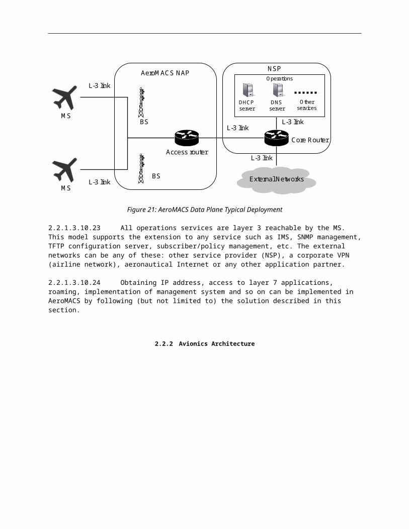
MS1 BS
PKMv2 (SA-TEK-Request)
PKMv2 (SA-TEK-Response / SAID1 = Crypto suite T125, I6SAID2 = Crypto suite T125, I1SAID3 = Crypto suite T125, I6)
SAID1 = Primary SA to be used by secure unicast connectionsSAID2 = Static SA with cryptographic suite set to no encryption to be used by multicast connectionsSAID3 = Static SA with cryptographic suite set to encryption to be used by multicast connections
DL SF creation (Target SAID = SAID1, CID1)
UL SF creation (Target SAID = SAID1, CID2)
DL SF creation (Target SAID = SAID2, CID3)
DL SF creation (Target SAID = SAID3, CID4)
CID1, CID2: encrypted unicast (DL and UL)CID3: Unencrypted multicastCID4: Encrypted multicast
2.5 PRIORITISATION AND QUALITY OF SERVICE
2.5.1 Introduction
2.5.1.1 This section provides guidance material on how the AeroMACS system will support the desired Quality of the Service (QoS) for the various applications including prioritisation of the applications.
2.5.1.2 The basic instrument in AeroMACS to support the required QoS by the applications is the use of service flows (SF) with appropriate QoS parameter configuration to comply with the application performance requirements on a per-service basis. This configuration leads to a priority and pre-emption based mechanism managed by the scheduler at the BS. This section proposes the methodology in which AeroMACS implementations will classify the upper layer application data into the MAC layer service flows (SF), in a worldwide interoperable way.
2.5.1.3 In addition, it provides guidance on how AeroMACS can support specific aeronautical requirements supporting specific ATC needs, while maintaining the required QoS, and describes the proposed solution on how to map AeroMACS QoS and priority scheme to ICAO ATN priority table.
2.5.1.4 The proposed approach implies that all supported service flows by an MS are created for the MS upon its entry into the AeroMACS network. Indeed it is proposed that AeroMACS is implementing a static service flow management with all supported service flows created even if they may not be used in the end. If a dynamic service flow management were chosen instead, then a service flow would be negotiated, established when needed and deleted when not needed anymore. However, the complexity of the dynamic approach is justifying any benefits of the static service flow management. Even if not the most efficient in terms of processing, it does not consume additional bandwidth resources. In addition, it can be used efficiently with different categories of users, or devices with different Service Flow requirements. It is important to note that AeroMACS technology can evolve for dynamic service flows management in case the system requirements change in the future or the benefits can justify the

1-10
additional complexity, while maintaining backwards compatibility.
2.5.2 Quality of Service (QoS) in AeroMACS
2.5.2.1 The AeroMACS QoS framework is based on the IEEE 802.16-2009 specifications. In summary, the IEEE 802.16-2009 systems are connection orientated at MAC level and they assign the traffic that needs to be transmitted to a Service Flow (SF) which is mapped to a MAC connection using a connection ID (CID). The 802.16-2009 specifications support the desired QoS for the applications using the following three mechanisms:
Bandwidth allocation Call Admission Control and Scheduling
2.5.2.2 The bandwidth allocation scheme is performed during initialization and network entry. In this process, the BS assigns dedicated CID to each MS in order to provide the MS the ability to send and receive control messages.
2.5.2.3 In the IEEE 802.16 standard bandwidth requests are normally transmitted in two modes: a contention mode and a contention-free mode (polling). In the contention mode, the MS sends bandwidth requests during a contention period, and the BS resolves contention by using an exponential back-off strategy. In the contention-free mode, the BS polls each MS, and an MS in reply sends its bandwidth request. The basic intention of unicast polling is to give the MS a contention-free opportunity to tell the BS that it needs bandwidth for one or more connections. In addition to polling individual MSs, the BS may issue a broadcast poll by allocating a request interval to the broadcast CID, when there is insufficient bandwidth to poll the stations individually.
2.5.2.4 The scheduler is the BS entity that manages the bandwidth allocation and transmission of queued MAC PDUs. Different scheduler classes use different bandwidth allocation schemes. Variable bandwidth assignment is possible in real time Polling Service (rtPS), non-real time Polling Service (nrtPS) and Best Effort (BE) services, whereas Unsolicited Grant Service (UGS) service needs fixed and dedicated bandwidth assignment. The BS periodically in a fixed pattern offers bandwidth for UGS connections so UGS connections do not request bandwidth from the BS.
2.5.2.5 The Call Admission Control (CAC) is the decision maker for incoming new services in the system. The admission controller implementation (and its performance) is vendor specific. When a MS sends a request to the BS with a certain QoS parameters for a new connection, the BS will check whether it can provide the required QoS for that connection. If the request is accepted, the BS verifies whether the QoS of all the ongoing connections can be maintained. Based on this it will take a decision on whether to accept or reject the connection. The process described above is known as CAC mechanism. The basic components in an admission controller are the performance estimator which is used to obtain the current state of the system, and the resource allocator which uses this state to reallocate available radio resource.
2.5.2.6 Then the admission control decision is made to accept or reject an incoming connection. A connection is admitted if there is enough bandwidth to accommodate the new connection. The newly admitted connection will receive QoS guarantees in terms of both bandwidth and delay and the QoS of existing connections must be maintained. A more relaxed rule would be considered to limit admission control decision (to reject) to applications with real time hard constraints, for example, airborne emergency call. For other requests if there are insufficient resources, one can provide throughput less than requested by them.
2.5.2.7 A simple admission control decision can be exercised if there are enough available resources in the BS, then new connections are admitted else they will be rejected. However, a simple admission BS have to deal with both uplink and downlink traffics. Therefore, there are three different schedulers: two at the BS to schedule the packet transmission in downlink and uplink sub frame and another at the MS for

uplink to apportion the assigned BW to its connections. 2.5.2.8 In order to indicate the allocation of transmission intervals in both uplink and downlink, in each frame, the signaling messages UL-MAP and DL-MAP are broadcasted at the beginning of the downlink sub frame. The scheduling decision for the downlink traffic is relatively simple as only the BS transmits during the downlink sub frame and the queue information is located in the BS, while an uplink scheduler at the BS must synchronize its decision with all the MSs.
2.5.2.9 Finally the scheduling algorithms provide mechanisms for bandwidth allocation and multiplexing at the packet level in IEEE 802.16-2009.
2.5.3 Pre-emption in AeroMACS
2.5.3.1 This section describes how pre-emption can be implemented in AeroMACS schedulers. In general, the scheduling techniques in the IEEE 802.16-2009 standards are still an area of development for both system vendors and academic researchers.
2.5.3.2 One example of uplink scheduler is depicted in the figure below [from “An Integrated Uplink scheduler in IEEE 802.16”, Elmabruk 2008]:
Figure 7 – Uplink WiMAX scheduler architecture example
2.5.3.3 In this architecture, an extra queue has been introduced to store a set of requests whose deadline is due to expire in the next frame.
2.5.3.4 In a scheduling cycle, the scheduler will check if any request has been added to this extra queue. If so, the scheduler will then serve this queue after the UGS and polling queue. Once the extra queue becomes empty and there is available bandwidth in the UL_MAP, the scheduler will continue serving the
rtPS CID1
rtPS CIDn
nrtPS CID1
nrtPS CIDn
BE
Server
Requests with earliest deadline
UGS
CLA
SS
IFIE
R
Frame n Frame n+1

1-12
PS list, using a round robin logic with priority for rtPS, followed by nrtPS. For BE, the remaining bandwidth will assigned using FIFO mechanism.
2.5.3.5 In IEEE 802.16-2009 (and therefore AeroMACS), depending on the specific system implementation, a scheduler can decide to pre-empt a message to push another message with higher priority (e.g., short latency requirement) into the outbound frame.
2.5.3.6 However, whether pre-emption will be needed or used, it will mainly depend on the scheduler performance, the active service flows demanding increased QoS, and the available bandwidth at any point in time, as under normal conditions there may not be a need for pre-emption. It is noted that the AeroMACS certification profile mainly aims at interoperability and radio performance and the scheduling performance is not covered.
<Editor’s note: Issue was discussed at WGS/7. Note is left to confirm approach and as a reminder to consider if anything is needed for this area (i.e test cases to measure scheduler performance?>
2.5.4 Service Flow Management
2.5.4.1 Service Flows (SFs) are required to transport AeroMACS services. Following the static service flow management approach in AeroMACS, they are created when MS enters the network and destroyed when MS exits the network.
2.5.4.2 A service flow is characterized by a set of QoS parameters. A service flow is a unidirectional channel. AeroMACS data services however, require bidirectional channels as some are based on TCP (i.e. data+ack) transport protocol. Therefore 2 SFs are normally needed for each exchange.
2.5.4.3 The classification rules map the higher level services to the corresponding SFs. The classification rules are loaded into the classifiers at both MS and BS when the SFs are created.
2.5.4.4 Based on past analysis and the WGS discussions, six different Classes of Service (CoS) have been identified as required for data services in AeroMACS. The identified data services (i.e., NET, ATS1, ATS2, ATS3, AOC2 and AOC) are shown in Table 1. Each of these data CoS requires different QoS parameters. The CoS are configured at the network side and provisioned to the Base Stations so that whenever a MS enters the network, the BS initiates the creation of Service Flows with the identified CoS. For the six data services, twelve services flows (i.e., 6 CoS x 2 SFs) are required for a single aircraft. In addition based in the WGS discussion up to three concurrent voice calls per aircraft need to be provisioned which results in six additional services flows being required to carry the 3 voice calls. The considered data and voice services and their QoS is described in Table 1.
2.5.4.5 For each CoS in Table 1, the QoS parameters include: latency, minimum and maximum rate, priority as shown in tables 2 and 3. Some QoS parameter values, such as the maximum latency and the minimum reserved rate, are directly imposed by the application QoS requirements.
2.5.4.6 It is highlighted that in the above context, traffic priority is only used to set priority between service flows with identical QoS parameters (like ATS1 and ATS2 in the example provided).
2.5.4.7 The Maximum Sustained Traffic Rate for high priority services can be determined by leaving 5% margin over the minimum reserved rate as rule of thumb for peak or buffering transitions. This margin is pessimistic and can be reduced if further analysis finds that another value is more adequate.
2.5.4.8 Adequate bandwidth should be assigned to the Best Effort class as a whole, because the majority of applications will default to this class; reserve at least 25 percent for Best Effort traffic.
2.5.4.9 The Maximum Sustained Traffic Rate for best effort services on the contrary cannot be determined from a single AeroMACS MS perspective. Multiple MSs are expected to fight for the available

bandwidth in the cell sector (DL: 9.1 Mbps, UL: 3.3 from Table 1 in MASPS), and therefore there is a need to set a upper limit on the bandwidth that the lowest priority services can consume for each MS, so that the whole cell capacity is distributed fairly among all connected MSs. Therefore, in order to determine the maximum sustained rate for the best effort services some calculations are required.
2.5.4.10 The first step is to quantify the bandwidth required by high priority services. Note that the figures in Table 1 are extracted from the draft AeroMACS MASPS (Table 44) and may change depending on a review of the AeroMACS performance requirements. The goal of this guidance is to show the methodology to determine the IEEE 802.16e QoS parameters values to be configured in the service flows.
Minimum reserved rate (from MASPS Table 44)
Maximum sustained rate (5% higher)
DL (kbps) UL (kbps) DL (kbps) UL (kbps)VoIP1 64 64 N/A N/AVoIP2 48 48 N/A N/AVoIP3 32 32 N/A N/ANET 32 32 34 34ATS1 32 32 34 34ATS2 32 32 34 34ATS3 32 32 34 34AOC1 64 128 67 134Total 267 334
Table 1 - Bandwidth (kbps) required by high priority services
2.5.4.11 This design will support up to three simultaneous Voice Calls on one single AeroMACS Mobile Station. A “calling manager” may be required to know the current status (busy with another call or available) of each SF before placing a new call.
2.5.4.12 Then, the available bandwidth per cell (i.e., the maximum sustained traffic rate QoS parameter value) can be derived from:
DL (Mbps) = 9.1 – (0.267+0.080) x A/CUL (Mbps) = 3.3 – (0.334+0.080) x A/C
2.5.4.13 Where A/C is the number of concurrent AeroMACS MS expected to be connected at the same cell sector and at the same time. That value depends on the airport size category in terms of operations/hour and the resulting cell planning.
2.5.4.14 For instance, in the case of airport with 3 operations/hours, the value deemed for AOC traffic on the RL according to MASPS Table 13 is 357.91 kbps for 1 A/C on the ground which falls within the estimations done in this guidance: 3.3-0.334 = 2.996 Mbps. This value is much higher than the required data throughout 357.91 kbps.
2.5.4.15 According to these figures, another consequence is that one single cell can guarantee a sustained rate 357.91 kbps up to 8 A/C (i.e., (3.3-0.357)/0.334) for best effort services and at the same time meet the other QoS requirements for their high priority services.
2.5.4.16 In the case of airport with 20 operations/hours, or higher, the number of sectors should be increased accordingly to handle the offered load. This guidance is to determine the QoS parameters per sector and thus independent from the airport capacity requirements.
2.5.4.17 In conclusion, (*: depending on the VoIP CODECS used. summarizes the IEEE 802.16e QoS

1-14
parameters values which can be used in the service flows in order to meet AeroMACS QoS requirements for voice and data services.
CoS Scheduling
QoS paremeters values in the AeroMACS service flows
Traffic priority
Maximum Sustained Traffic Rate (kbps)
Minimum Reserved Traffic Rate (kbps)
Maximum Latency (s)
Voice UGS N/A DL/UL: 64 64* DL/UL: 0.150NET rtPS N/A DL/UL: 34 32 DL/UL: 1ATS1 rtPS 1 DL/UL: 34 32 DL/UL: 1.5ATS2 rtPS 2 DL/UL: 34 32 DL/UL: 1.5ATS3 nrtPS N/A DL/UL: 34 32 N/A
AOC1 nrtPS N/A DL: 67UL: 134
DL: 64UL: 128 N/A
AOC2 BE N/A
DL: 9100 – 0.267 x A/CUL: 3300 – 0.334 x A/C
N/A N/A
*: depending on the VoIP CODECS used.Table 2 - QoS aparameters values in AeroMACS (based on MASPS)
2.5.4.18 In the table above, the maximum latency values refer to end to end application layer delay and are extracted from the draft AeroMACS MASPS. These values could become more stringent if necessary to keep the underlying requirement of one-way delay of 20 to 80 ms at MAC layer as indicated in section 7.1 in the AeroMACS MASPS.
It is noted again that the traffic priority field resolves potential competition between CoS with the same otherwise QoS parameters set.
2.5.4.19 Even if a static service flow management is proposed, this approach is compatible with evolution and can support new classes of service to be defined to support new type of applications. In order to achieve this new service flows (for the new CoSs) will need to be configured in the AeroMACS ASN, if the AeroMACS QoS requirements change over time and as a result more granularity is required in the definition of class of services. In such a case, the maximum number of active services flows supported by the MS and the ASN should be considered as granularity limit. The IEEE 802.16e std. does not set a requirement on that.
2.5.4.20 As an example an Airport Operations (APT) application for e.g. video streaming at 1000 Mbit/s and other best effort services in the Table below show an example on how two new APT type of CoS can be added to the list of supported CoS.
CoS Scheduling
QoS paremeters values in the AeroMACS service flows
Traffic priority
Maximum Sustained Traffic Rate (kbps)
Minimum Reserved Traffic Rate (kbps)
Maximum Latency (s)
Voice UGS N/A DL/UL: 64 64* DL/UL: 0.150NET rtPS N/A DL/UL: 34 32 DL/UL: 1ATS1 rtPS 1 DL/UL: 34 32 DL/UL: 1.5ATS2 rtPS 2 DL/UL: 34 32 DL/UL: 1.5ATS3 nrtPS N/A DL/UL: 34 32 N/A

AOC1 nrtPS N/A DL: 67UL: 134
DL: 64UL: 128 N/A
AOC2 BE N/A
DL: (8100 – 0.267 x A/C)/2UL: (3300 – 0.334 x A/C)/2
N/A N/A
APT1 BE 1 DL: 1000 N/A N/A
APT2 BE 2
DL: (8100 – 0.267 x A/C)/2UL: (3300 – 0.334 x A/C)/2
N/A N/A
Table 3 - QoS parameters values in AeroMACS providing APT support
2.5.4.21 For a better management of the number of SFs to be activated for each MS, it is possible to define Device Classes that will implement only some CoSs. For example voice only devices would only use two or more SFs (DL and UL) with just the Voice CoS. Similarly video streaming only devices (such as security cameras) would only use one SF (DL) with APT1 CoS.
2.5.4.22 The QoS policy provisioning between AAA and ASN is described in WiMAX Forum NWG specification and can be extended to support the Device Classes provisioning.
2.5.4.23 In summary, the Service Flow Management (SFM) is a logical entity in the ASN. The SFM entity is responsible for the creation, admission, activation, modification and deletion of Service Flows. The precise definition of the admission control functions is left to implementations.2.5.4.24 Similarly, the Service Flow Authorization (SFA) is a logical entity in the ASN. The SFA is responsible for evaluating any service request against user’s QoS profile (i.e., Device Class) in the case when it is downloaded from the AAA Server. AAA server holds the user's QoS profile and associated policy rules. They are downloaded to the SFA at network entry as part of the authentication and authorization procedure.
2.5.4.25 SFA/SFM entities can provide the capability to provision specific SFs per device classes

1-16
depending on the SFA policies. In addition, there is support for evolution of requirements and introduction of new device classes as the requirement to create new Service Flows in the future (for instance to transport Video HD), resides in the network side. Therefore legacy MSs do not need to implement anything new as they will ignore the new service flows and continue using the previous service flows.
2.5.5 Mapping of AeroMACS priority levels to ICAO ATN priority levels
2.5.5.1 In order to support the QoS service requirements for the ATC and AOC services, a priority classification per message category is defined by ICAO and mapped to the supported ATN mobile subnetworks in table 3-3 of Annex 10 Vol III. Considering the ATS and AOC classes of service as defined in the previous sections, the following table provides a mapping of the AeroMACS services to the ATN network layer priority levels.
Message categories ATN network layer priority
Corresponding mobile subnetwork priorityAeroMACS
Network/systems management 14 NETDistress communications 13 ATS1Urgent communications 12 ATS1High-priority flight safety messages 11 ATS1Normal-priority flight safety messages 10 ATS2Meteorological communications 9 ATS3Flight regularity communications 8 AOC1 or AOC2Aeronautical information service messages
7 ATS3
Network/systems administration 6 ATS3Aeronautical administrative messages 5 Not allowed<unassigned> 4 <unassigned>Urgent-priority administrative and U.N. Charter communications
3 Not allowed
High-priority administrative and State/Government communications
2 Not allowed
Normal-priority administrative communications
1 Not allowed
Low-priority administrative communications and aeronautical passenger communications
0 Not allowed
Note: The information in the 3rd column of this table is equivalent to the columns defined in Table 3-3 of Annex 10 Volume III for the other mobile subnetworks.
2.5.6 Quality of Service in Internet Protocol (IP QoS)
2.5.6.1 Aeronautical network comprises multiple autonomous networks, managed by different administrative domains and interconnected to each other to form the global internet. In this scenario, the end to end Quality of Service (QoS) can only be achieved by defining a common set of rules for packet handling that could be applied uniformly across various networks.
2.5.6.2 IETF defines two methods of QoS handling for packets in the Internet (IP QoS) namely, Integrated Service (IntServ) and Differentiated Service (DiffServ).
2.5.6.3 Integrated Service is a parameterized system based model in which, end applications negotiate QoS parameters with the network and reserve resources for the entire path of its traffic flow. Generally, Resource Reservation Protocol (RSVP) is used for negotiating QoS parameters and reserving network

resources.
2.5.6.4 Differentiated Service is based on a prioritized traffic model in which the application packets are marked for various QoS handling and the network prioritizes them as per the predefined set of rules. Diffserv model defines Per Hop Behaviours (PHB) for various QOS categories and the routers and switches in the network implement packet handling algorithms as per the PHB definitions.
2.5.6.5 In practice, IntSev model is difficult to implement as it requires additional implementation of RSVP protocol to manage session creations and teardowns in the network for various traffic flows between end applications. DiffServ model does not require any such session based negotiations. Hence, compared to IntServ model, DiffServ model is simpler to implement and maintain. Therefore DiffServ model is recommended in “Manual for the ATN using IPS Standards and Protocols (Doc 9896)” for ATN-IPS applications.
2.5.6.6 DiffServ Model
2.5.6.6.1 In DiffServ specifications (IETF RFC 2474) an 8-bit Differentiated Service Field (DS Field) is defined in the IP Header for packet marking and classification purposes. Initial 6-bits of DS Field represent Differentiated Services Code Point (DSCP) that defines the class of service or in other words called Per Hop Behaviours (PHB) required for the packet in the network. The next 2 bits are used for Explicit Congestion Notification (ECN) which is outside the scope of DiffSev.
2.5.6.6.2 In IPv4 Header, ‘Type of Service (ToS)’ field is practically not in use in the current internet implementations and hence, RFC 2474 redefines ToS as DS Field, while, In IPv6 Header, ‘Traffic Class field’ represents DS Field. (see Figure . X & Y). Since, the DSCP definitions are common between IPv4 and IPv6 networks, the packets are expected to receive the same kind of QOS treatment in the DiffServ network irrespective of the network layer protocol.
Figure - X IPv4 Header
Ver Length ToS Flags Checksum IP Options...
Used as DS field
Source Address
Payload Length
TrafficClass Flow LabelVer
Next Header Hop Limit
Destination Address
Used as DS field

1-18
Figure Y- IPv6 Header
2.5.6.6.3 DiffServ defines 3 categories of PHBs namely, Expedited Forwarding (EF), Assured Forwarding (AF) and Default (DF) Forwarding as shown in Figure- XX,
-
Figure – XX DS Field
• Expedited Forwarding (EF) is dedicated to low loss, low delay Traffic. Generally EF is used for voice applications. EF specifications are defined in RFC 3246.
• Assured Forwarding (AF) – Assured forwarding allows the operator to provide assurance of delivery as long as the traffic does not exceed some subscribed rate. The traffic exceeding the allowed data rate is likely to be dropped in case of congestion. Diffserv defines four AF groups where all have the same priority. Within each class, packets are given drop precedence as high, medium or low, where higher precedence means more dropping. The combination of classes and drop precedence yields twelve separate DSCP encodings from AF11 through AF43 (see table).
Assured Forwarding (AF) Behavior Group
Class 1 Class 2 Class 3 Class 4
Low Drop AF11 (DSCP 10) AF21 (DSCP 18) AF31 (DSCP 26) AF41 (DSCP 34)
Med Drop AF12 (DSCP 12) AF22 (DSCP 20) AF32 (DSCP 28) AF42 (DSCP 36)
High Drop AF13 (DSCP 14) AF23 (DSCP 22) AF33 (DSCP 30) AF43 (DSCP 38)
Table -
2.5.6.6.4 AF classes are independent of each other and benefit individual guaranteed bandwidth. This prevents one critical application to take all the available bandwidth and block other critical applications. AF is defined in RFC 2597 and updated in RFC3260.

• Default Forwarding (DF) – A best effort class which would be used for non mission critical, non-delay sensitive applications.
2.4.6.7 Traffic Handling in Network
2.5.6.7.1 Packets entering DiffServ networks shall be classified and scheduled as per the DSCP markings. Applications decide the DSCP settings based on their requirements and set the DSCP values in the IP header. Most TCP/IP implementations provide mechanisms (example: Socket Options) for setting IP Header values. Using such provisions DSCP values shall be set into ToS filed (in case of IPv4 network) or in Traffic Class field (in case of IPv6 network).
Figure – YY Traffic Handling in Network
2.5.6.7.2 Routers, switches or any other intermediate modules in the network handle packets as per PHB definitions. Based on the DSCP settings, the packets are classified; priority is applied and scheduled for further transmission in the network. The packets may traverse through a series of networks, but, since, at every network node, the packets are handled as per the PHBs set by the applications, end to end QoS is achieved in the entire network.
2.5.6.7.3 Another aspect to be considered in the overall network design is to implement the required QoS at MAC/Lower layers also in line with IPQoS requirements. In most cases, Layer 2 systems have their own QoS definitions which may be different from IP-QoS definitions, as Layer 2 systems handle packets from multiple network layer (Layer 3) systems. For example: The definitions of AeroMACS service types are different from IP QoS definitions. Hence it becomes necessary to map IP QoS definitions with AeroMACS service classes to achieve end to end QoS performances.
2.5.6.8.Mapping IP QoS with AeroMACS Service Flows
2.5.6.8.1 Various applications and their classes of service are identified in the earlier sections (Section
All network components like routers and switches,
Radios map IP Level Diffserv QOS to their MAC level QOS
Network prioritizes packets depending upon the DSCP
Applications Mark IP packets (Set DSCP bits) depending upon the criticality . TOS – in case of IP
A/C End Systems
Ground Station Ground Network Datalink
Radios
Aircraft Network
A/C End Systems
Air- Ground Network

1-20
xxx) ( as in Euro control paper).The table below defines a mapping between DiffServ PHBs and AeroMACS service flows based on their definitions.
2.5.6.8.2 AeroMACS shall be supporting only Push To Talk (PTT) radios for ATC and AOC communications. Hence audio bandwidth is required only when the ‘Push’ button is pressed in the handset. Moreover, advanced voice coders with features like Active Voice Detection and Silence Suppression are used in the existing audio units of aircraft and ground systems. Hence there may not be a need to allocate dedicated bandwidth for voice services permanently at AeroMACS level. Therefore ertPS service is allocated for voice services and they are mapped to Expedited Forwarding (EF) in IP QoS.
2.5.6.8.3 NET traffic corresponds to network control and management packets. It is mapped to AF31 PHB at IP level and allocated with rtPS connection at AeroMACS level.
2.5.6.8.4 Per Section XXX, three rtPS connections are identified for ATS services such as, ATS1, ATS2, and ATS3. ATS1 and ATS2 services are identified as rtPS services, while lesser critical ATS3 service is identified as nrtPS service as per section XXX definitions. These services are assigned with PHB values namely, AF32, AF33 and AF11 respectively.
2.5.6.8.5 An emergency video service is introduced with a PHB value of AF23 mapping to rtPS service at AeroMACS level. This shall be used only in emergency situations for transferring pictures.
AF4X , AF21, AF22, AF12 are reserved for future traffic categories
AeroMACS supports Classification rules
based on DSCP

2.5.6.8.6 AOC1 service having nrtPS connection is mapped to the PHB value of AF13.
2.5.6.8.7 All other services namely AOC2, APT1 and APT2 are mapped to BE (Default PHB).
2.5.6.9 Device Classes
2.5.6.9.1 AeroMACS network is expected to support a variety of deployments at airports including mobile/fixed terminals, safety/ non-safety equipments, real-time/non-real-time applications etc. Hence, depending upon deployment requirements, device configurations of SS such as, types of services to be provisioned, number of connections and data rates would differ on a case by case basis. Hence there is a need to define device classes identifying mandatory requirements for each deployment.
Table below contains identified device classes and the mandatory service provisions required for each class.
CoS SchedulingIP QOS
AircarftSurface Vehicle
Video Sensor
Ground Critical
Ground Default
Traffic priority PHB
Voice ertPS N/A EF X XNET rtPS N/A AF31 X X X X XATS1 rtPS 1 AF32 X X XATS2 rtPS 2 AF33 X
Video (E) rtPS N/A AF23 XATS3 nrtPS N/A AF12 xAOC1 nrtPS N/A AF13 xAOC2 BE N/A
DF Default Supported by all devices APT1 BE N/A
APT2 BE N/A
2.5.6.9.2 Network Control/Management (NET) and Default (DF) connections are provisioned for all device classes. Only the additional connections are discussed below.
Aircraft - represents modems installed in aircraft. Considering both safety and non-safety applications all identified types of connections are recommended for aircraft except Video connection. Aircraft devices shall be provisioned with additional 5 connections i.e. VOICE, ATS1, ATS2, ATS3 and AOC1
Surface vehicle – represents devices hosted on all ground support vehicles including passenger vans/buses, dollies carrying cargo, refuel trucks, catering vehicles and Push back tugs/ tractors etc., Generally, most of these vehicles are equipped with PTT phones. In addition, A-SMGCS (Advanced Surface Movement Guidance & Control System) may require a safety link for exchanging vehicle’s position information on a periodic basis to a centralized control system. Hence this device class shall support VOICE and ATS1 connections.
Video Sensor – shall be used for sending videos during emergency situations. Hence a VIDEO connection is recommended for this class.
Ground critical – represents devices used to monitor/control ground equipments that are deployed for critical ATS services. Example: RADARS, Landing Systems, Runway Lighting controls etc. ATS1 connection is recommended for these devices.

1-22
Ground Default – All other ground equipments fall under this default category. No additional connection is provisioned for this class.
2.5.6.9.3 The identified services flows are recommended as mandatory for the device classes, but, this may not restrict an AeroMACS service provided to offer more provisions for a device depending upon the availability of his network resources.
2.5.6.10 Identification of Devices
2.5.6.10.1 The network may need to know the device class for providing the right kind of services to a device. This section explains a mechanism for that.
2.5.6.10.2 During logon, as part of credibility establishment process, the digital certificate of a device is exchanged with the network. AeroMACS specifications have defined certificate profiles for devices and service providers. The device certificate profile has a field called “tbsCertificate.subject” that is used to provide the identity of the associated device.
2.5.6.10.3 This field can be used to indicate the device class information also along with its id as shown below:
tbsCertificate.subject : <Device Type> < Device Id>
- While registering, device credentials along with its device type shall be provided to Certificate Authority (CA). CA shall create a certificate for the device and sign it.
- During logon procedure, the device exchanges the certificate with the AeroMACS network. - AAA server or the Authenticator validates device certificate and identifies its device class. - Authenticator has profile definitions for various devices as per the recommendation is section
AAA
During Logon AAA server identifies the
device type and based
ASN / BS configured to support
Certificates have device
Type
ASN
tbsCertificate.subject : <Device Type><Id>
AeroMACS CPE

3.4.5. Based on the profile definition corresponding to the device class, AAA server instructs ASN network to initiate link establishments with the device accordingly.
2.5.6.10.4 In practice, it is possible that the devices are certified by different Certificate Authorities (CA) with different levels of scope. For example: Aircraft certificate may have the global scope, while the certificate of a surface vehicle may have a local scope corresponding to an airport. Hence the Authenticator shall have the required trace paths available for all applicable devices in order to validate their certificates.
2.6 Sub-Network Entry and Scanning Time
2.6.1 This section describes the process by which AeroMACS scans and establishes a communications channel with a BS, to enter an AeroMACS network. IEEE 802 16-2009 defines the network entry and initialization process, which is shown below in Figure. 1.
2.6.2 The starting point, as defined in IEE 802.16-2009, begins when an SS starts scanning for a DL channel.
2.6.3 The end point of the network entry time is when the SS receives a DSA-ACK message, which means that a network link has been established. Following receipt of a DSA-ACK message, an SS is able to send data to a network.
2.6.4 In general, AeroMACS is a part of an end-to-end network, hence the definition of network entry time should be amended to be read, sub-network entry time, as follows.

1-24
Figure.1 Initialization overview flow chart referenced by IEEE 802.16-2009
2.6.5 As a number of factors, contribute to the Sub Network Entry time, it is useful to divide it into two components; Sub Network Entry Time T1 and Sub Network Entry time T 2.
The Sub Network Entry time = Sub Network Entry time T1 + Sub Network Entry Time T2
Sub Network Entry time T1; mainly depends on the MS implementation. Sub Network Entry time T2; mainly depends on the RF environment between the MS and
BS.
1) Sub Network Entry time T1
The Sub Network Entry time T1 should be defined as following procedure.
(1) MS starts scanning the BS transmitted frequency.
Scanning frequency band should be defined. Scanning method of MS is implementation issue.

(2) MS selects the best frequency for synchronizing
(3) MS synchronizes to BS frame
(4) MS sends Initial Ranging code
The starting point should be considered to be the starting point of Sub Network entry time,
This Entry time depends on the condition of scanning frequency bandwidth, and also depends on the MS implementation issue for scanning and selecting the best channel.
2) Sub Network Entry time T2
For Sub-Network Entry Time T2, the starting point and end point are defined as follows. As is shown in Figure 2, the starting point is when the MS sends an Initial Ranging code. The end point is when the MS receives the DSA-ACK message.
Unlike Sub-Network Entry Time T1, Sub-Network Entry Time T2 does not depend on the frequency bandwidth however it is dependent on the RF environment. If the radio environment is noisy and an adequate S/N ratio cannot be achieved, the sequence may not proceed as shown if frames need to be resent.
Figure 3 shows sequence of T1 and T2 for total Sub Network Entry Time.
The start point of Sub Network Entry time T2 should be defined as sending of Initial Ranging code Initial Ranging code
RNG-RSP
MS BS Network

1-26
Figure.2 The definition of Sub Network Entry time T2
RNG-REQ
RNG-RSP
Authentication Process
DSA-RSP
DSA-ACK
The end point of Sub Network Entry time should be defined as receiving the DSA-ACK message
DSA-REQ
Detail sequence is omitted
The definition of Sub Network Entry Time T2
SBC-REQ
SBC-RSP
REG-RSP
REG-REQ
MS synchronizes to DL of BS
T1
MS Scans for DL Channel
Ranging & Automatic Adjustments
Negotiate Basic Capabilities between MS and
MS Selects best channel to synchronize

Figure 3 Sequence of T1 and T2 for total Sub Network Entry Time.
Negotiate Basic Capabilities between MS and

2-28 Manual 10044
2.7 HAND-OFF
2.7.1 This section describes the AeroMACS handover procedures and explains how handover is done in AeroMACS systems including some practical aspects to consider in a real deployment.
2.7.2 As a reminder, the AeroMACS SARPs (7.3.13) require in the general requirements that “AeroMACS shall support handover between different AeroMACS BSs during aircraft movement or on degradation of connection with current BS”.
2.7.3 In relation to handover, the IEEE 802.16-2009 standard defines three relevant handover mechanisms:
MS initiated handover
MS initiated handover with scanning
BS initiated handover
2.7.4 The AeroMACS MOPS and Profile require that all AeroMACS systems support MS initiated handover mechanisms and these two mechanisms are described in the following sections. In addition general considerations for real deployments and practicalities to better understand how handover procedures operate in AeroMACS are also provided.
2.7.5 In terms of which of the two mechanism to use (with or without scanning), this is a design option as explained below.
2.7.6 MS initiated Handover
2.7.6.1 MS initiated handover is the simplest AeroMACS handover process where the MS chooses the candidate Target BS based on its Serving BS Neighbour Advertisement information and not on the actual channel conditions. The following diagram describes the MS initiated handover and exchanges that take place between the MS and the two BSs involved (Serving and Target).
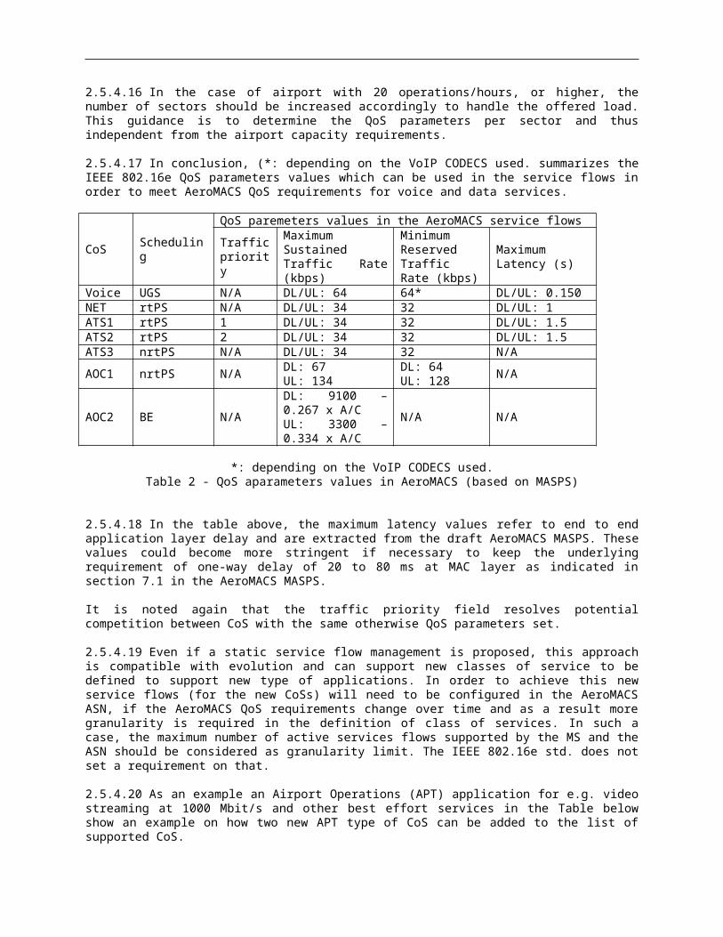
MS Serving BS Target BS
MOB_NBR-ADV
MOB_NBR-ADV
HO trigger condition met
MOB_MSHO-REQ
MOB_BSHO-RSP
Connection established
MOB_HO-IND
Network re-entry
(1)
(2)
(3)
(4)
2-29
Key:
MOB NBR-ADV: Neighbour Advertisement MOB MSHO-REQ; Mobile Station Hand-Over RequestMOB BSHO-RSP; Mobile Station Hand-Over ResponseMOB HO-IND: Mobile Handover Indication
Figure 7- MS initiated Handover
2.7.6.2 The different exchanges in the MS initiated handover are described below:
1) Successful completion of initial network entry and service flow establishment.
2) Acquiring Network Topology - Neighbour Advertisement
2.1) The Serving BS and the Target BS send MOB_NBR-ADV. An AeroMACS BS broadcasts information about the network topology using the MOB_NBR_ADV message, which is a AeroMACS layer 2 Management message. This message provides channel information about neighbouring BSs.
The Serving BS sends Neighbour Trigger TLV in MOB_NBR-ADV. The type of metric (RSSI or CINR), function (Metric of neighbour BS is greater/less than absolute value or than sum of serving BS metric and relative value), action (Respond on trigger with MOB_MSHO-REQ) and value of the trigger are defined in the Neighbour Trigger TLV [7].
3) Handover Decision
3.1) When the trigger conditions are met, the MS sends one or more MOB_MSHO-REQ to the Serving BS.
3.2) The Serving BS sends MOB_BSHO-RSP.
3.3) The MS optionally sends MOB_HO-IND to the Serving BS with final indication that it is about to perform a HO.

2-30 Manual 10044
4) Handover Initiation
Key:
TLV: Type, Length, Value – a tag added to each transmitted parameter containing the parameter type, the length of the encoded parameter and the value.
2.7.7 MS initiated Handover with scanning
2.7.7.1 In the MS initiated handover with scanning process, the MS uses its Serving BS Neighbour Advertisement, not to initiate the handover itself, but to initiate the scanning for the candidate BSs thus determining the actual channel conditions before performing the handover action. This process however increases the handover latency. The following diagram describes the MS initiated handover with scanning and exchanges that take place between the MS and the BSs involved (Serving BS and BS#1).
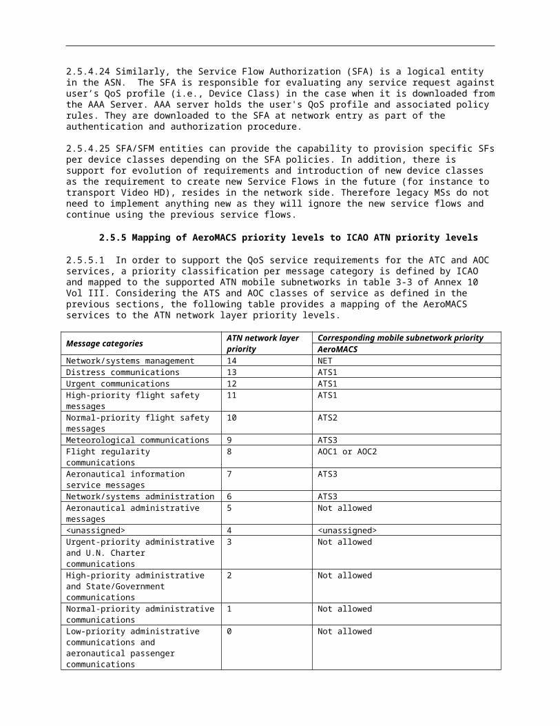
MS Serving BS BS#1
MOB_NBR-ADV
Connection established(1)
(2)
Scan trigger condition met
MOB_SCN-REQScan duration = N frames
Interleaving Interval =PIteration = T times
MOB_SCN-RSPStart frame = M frames
Duration = N frames
(3)
M frames
N frames
Synchronize with Candidates BS- Measure metrics
- Decode UL/DL-MAP
P framesTraffic Data (if any)
#1
Repeat Scanning up to #T times
HO trigger condition met
MOB_MSHO-REQ
MOB_BSHO-RSP
MOB_HO-IND
Network re-entry
(4)
(5)
2-31
Key: MOB NBR-ADV: Neighbour Advertisement MOB SCN-REQ: Mobile Scanning RequestMOB SCN-RSP: Mobile Scanning ResponseMOB MSHO-REQ; Mobile Station Hand-Over RequestMOB BSHO-RSP; Mobile Station Hand-Over ResponseMOB HO-IND: Mobile Handover Indication

2-32 Manual 10044
Figure 8 - MS initiated Handover with scanning
2.7.7.2 The different exchanges in the MS initiated handover with scanning are described below:
1) Successful completion of initial network entry and service flow establishment
2) Acquiring Network Topology - Neighbour Advertisement
2.1) The Serving BS sends MOB_NBR-ADV.
The Serving BS sends Scanning Trigger TLV in DCD and/or MOB_NBR-ADV. Scanning Trigger TLV is a Neighbour TLV with action = 0x1(Respond on trigger with MOB_SCN-REQ).
The Serving BS sends HO Trigger TLV in DCD and/or MOB_NBR-ADV. HO Trigger TLV is a Neighbour TLV with action = 0x2 (Respond on trigger with MOB_MSHO-REQ).
2.2) The Serving BS sends UL interference and noise level (dBm) estimated in BS using Noise plus interference IE in DL-MAP.
3) Acquiring Network Topology - Scanning Initiation
3.1) When the scan trigger condition is met, the MS sends one or more MOB_SCN-REQ indicating preferred scanning parameters. This message includes the scanning values for Scan Duration (N), Interleaving Interval (P) and Iterations (T).
3.2) The Serving BS sends MOB_SCN-RSP with scanning parameters. This message includes the scanning values for Start Frames (M) and confirms Duration (N).
3.3) The MS scans neighbour BSs during scan interval as defined in MOB_SCN-RSP.
4) Handover Decision
4.1) When the handover trigger condition is met, the MS sends MOB_MSHO-REQ indicating the Target BS.
4.2) The Serving BS sends MOB_BSHO-RSP with action time > 0 indicating fast ranging IE is used in Target BS and optionally the HO_ID.
4.3) The MS sends MOB_HO-IND to the Serving BS with HO_IND_type = 0b00 (serving BS release).
5) Handover Initiation
2.7.7.3 The information of neighbour BSs in the MOB_NBR-ADV may include: Preamble Index, Least significant 24 bits of BSID, Frequency assignment, BS EIRP, DCD/UCD Configuration Change Count, Scheduling Service Supported, and HO Process Optimization.
2.7.7.4 However should the MS choose the BS candidate based on this information, the MS may not select the more suitable BS. The MS does not know at this point the actual channel conditions to the candidates BS. Based on MOB_NBR-ADV, the MS only knows that the surrounding BSs exist and how to synchronize with them, but nothing else.
2.7.7.5 By sending MOB_SCN-REQ, the MS uses this neighbour list, not to initiate the handover itself, but to initiate the scanning of the candidate BSs. By scanning the MS learns the actual channel conditions (RSSI or CINR0) and then selects the more suitable BS to perform the handover. The cost is that this
0 RSSI: The level of signal strength including noise.CINR: The channel "quality" of the modulated carrier.Low RSSI values are usually caused by channel fading and attenuation.

2-33
scanning procedure takes some time (in term of number of frames) thus increasing the handover total latency.
2.7.7.6 This additional latency due to scanning depends on the number of neighbour BSs the MS is granted to scan by the serving BS. In AeroMACS, where no many BS are expected to be deployed, this latency may not be very long (only a few frames interval).
2.7.7.7 Scanning will enable AeroMACS MSs to perform reliable handovers. Additionally, as only a few BSs will be present in AeroMACS, the latency introduced by scanning should not be high.
Note: The duration and frequency of scanning and the interleave scanning periods and normal operations could affecting the network performance and provided QoS. A long scanning period increases the packets’ jitter and the end-to-end latency because while the MS is scanning, the BS sees it as “sleeping” and will buffer its packets until the scanning is done. Contrarily, a short scanning period requires multiple iterations and increases the overall scanning duration. In general longer scanning periods may lead to worse QoS operations (higher delay jitter) but better handover performance (solid connectivity for delay and bandwith sensitive services).
2.7.7.8 In any case, if the benefit from using scanning is not worthy of the additional latency introduced, it can just not be used. For this to happen, the BS can be configured to send MOB_NBR-ADV with Neighbour Trigger TLV with action set to “Respond on trigger with MOB_MSHO-REQ”.
2.7.7.9 In relation to the optimum values for parameters N, P and T, there are not many references available. One study (paper in http://www2.ensc.sfu.ca/~ljilja/ENSC427/Spring09/Projects/team10/ report_ENSC_427-2nd.pdf) identifies that for a stationary node, a long scanning duration would not be useful. In addition, it identifies that for a mobile node, such as a vehicle, the scanning duration is crucial in maintaining good connectivity for delay and bandwidth sensitive services such as voice-over-IP or video conferencing.
Table 1x provides the latency and jitter performance based on selected sets of N, P and T parameters.
Table 1x: N, P and T parameter Values and resulting latency and jitter performance
Parameter Light Scanning Dense ScanningScan Duration (N) 4 frames 20 framesInterleaving Interval (P) 350 frames 140 framesIterations (T) 10 frames 10 framesPerformanceLatency 48 ms 60 msJitter 22 ms 33 ms
2.7.8 HO Ranging
2.7.8.1 HO Ranging is not an additional HO procedure, but it is performed typically in the case of a HO failure and it allows a quick link recovery. In this case, instead of the MS sending a MOB-MSHO-REQ at the serving BS the MS directly moves to the target BS and performs handover ranging to re-enter the network.
Low CINR values are usually caused by co-channel, or adjacent channel interference.

2-34 Manual 10044
Figure 9 - HO Ranging
2.7.8.2 In this scenario the MS is aware for the BS to choose based on the information learnt from the Serving BS MOB_NBR-ADV messages. This is an implementation option and as far as the delay and availability of the data path to the MS complies with the requirements, it can be up to the MS internal algorithm to pick a BS based on parameters such as signal strength, RSSI, and available capacity.
2.7.8.3. There are two ways to perform HO ranging:
A. Handover CDMA ranging codes in the Initial Ranging Interval (described in 6.3.21.2.6 of IEEE 802.16-2009 standard).
B. Use Fast Ranging IE (described in 6.2.21.2.4 of IEEE 802.16-2009 standard). MS can receive the Fast_Ranging_IE in the UL-MAP to allocate a non-contention-based initial ranging opportunity and can transmit an RNG-REQ code to the target BS without access collision.
2.7.8.4 The AeroMACS profile supports both options A and B to perform HO ranging and both scenarios are certified by the WiMAX Forum.
2.7.9 Practicalities for understanding of HO in AeroMACS
2.7.9.1 Two handover procedures are allowed in AeroMACS, both initiated by the MS. Overall, the use of MS initiated handover with or without scanning is a design option and the decision which to option to use is taken by the MS. MS initiated handover relies on MOB_NBR-ADV accuracy, while MS initiated handover with scanning provides a way for the MS to make sure the channel conditions are good, at the expense of introducing an additional delay.
2.7.9.2 For the Scanning case, once the metric trigger happens, the MS initiates HO to the target BS. The point of having already received the MOB_NBR-ADV information is that the MS knows already all it needs to associate to the target BS.
2.7.9.3 With the Scanning case, once the metric trigger happens, starting from the Start Frame specified by the serving BS, the MS only synchronizes to the candidate BSs (for monitoring signal quality and UL/DL-MAPs) while it remains associated to the serving BS. This happens during the scanning intervals as granted by the serving BS.
2.7.9.4 During the scanning interval the MS does not exchange data with the serving BS as the MS radio is busy performing the scanning. However, the serving BS is allowed to preset a certain buffer space to store

2-35
downlink service data when an MS performs scanning.
2.7.9.5 The benefit of using the option with Scanning is that it provides a more reliable handover procedure (i.e. lower probability of HO failure), in exchange for a higher latency, which would be in the order of a few frames (one frame being 5 ms).
2.7.9.6 According to the WiMAX Forum Network Working Group standards, the serving BS obtains the neighbouring BS information from the ASN-GW over the R6 interface. How the serving BS obtains the list of the neighbour BS when the backbone network is not utilized remains outside the scope of WiMAX Forum Air Interface Certification.
2.7.9.7 The chronicle order of listing these neighbouring BS within the MOB_NBR-ADV to reflect the relative location of the MS with neighbouring BS is something not specified in the IEEE standard. This interpretation is not considered in the WiMAX certification HO test cases.
NOTE: Additional information for handover is provided in the “Handover procedures supported by the WiMAX Forum System Profile” developed by EUROCONTROL/AT4W (Technical Note #12) and submitted as WPXX to the AeroMACS ICAO group <to discuss with secretariat how /where to capture relevant/supporting documents…>
2.8 Upper Layer Interfaces
2.8.1 Convergence Sublayer
2.10.1.1 The Convergence Sublayer (CS) interfaces with higher layers to accept packets from higher layers and to transfer them to the MAC Common Part Sublayer (MAC CPS) for further processing. This layer is also responsible for categorizing the packets as per packet classification rules, mapping them to the associated service flows and scheduling them for transmission over the MAC layer based on Quality of Service (QoS) definitions. CS also performs Packet Header Suppression optionally. AeroMACS supports packet Convergence Sublayer (packet CS), including both Ethernet Specific and IP specific parts. AeroMACS does not support Asynchronous Transfer Mode Convergence Sublayer (ATM CS) and Generic Packet Convergence Sublayer (GPCS) as AeroMACS is not expected to support networks other than Ethernet and IP.
2.8.1.2 Packet Classification
2.8.1.2.1 The packets from various applications are received at CS-SAP interface of AeroMACS systems. The airport terminal applications may fall into various levels of criticality depending upon their purposes. For example: ATC voice data over AeroMACS is a safety critical real-time application, but, downloading of engine data is not a critical application. Hence ATC voice data should have higher priority and stringent jitter performances in the network compared to the engine download data. To support ATC voice application, Unsolicited Grant Service (UGS) may be used at AeroMACS level, while engine data download could be supported with Non Real-time Polling Service (nrtPS) or with Best Effort (BE) Service. Hence there is a requirement to classify the incoming packets at AeroMACS level into various service flows and apply the required QoS treatment to the packet traffic. AeroMACS has a provision to specify packet classification rules so that the incoming traffic can be divided into multiple data streams. Associated to the classification rule, type of service flow, QoS policies and Packet Header Suppression policies can also be specified for each data stream. The packet classification rules are defined based on some of the packet header parameters such as, UDP port numbers, IP addresses (source or destination) or by a combination of multiple parameters. Based on the classification, individual service flows are created and the packets are scheduled accordingly as shown in the figure CS-1

2-36 Manual 10044
Figure CS -1 Packet Classification
2.8.1.2.2 Many classification rules may be associated with a service flow. In such cases priority rules are set to order the packets for transmission through the connection.
2.8.1.3 Payload Header Suppression
2.8.1.3.1 Payload Header Suppression (PHS) function helps to remove the redundant packet header information transmitted repeatedly between Base Station (BS) and Subscriber Stations (SS) over the air interface, in order to reduce the wireless bandwidth consumption. Consider an application sending messages over an UDP connection. Every packet originating from the application will have mostly the same UDP and IP header parameters (except a few like checksums, length etc.) added to all application payloads. Therefore, it is possible to suppress such redundant header information before packet transmissions over the air and reconstruct them back after the reception on the other end and save wireless bandwidth. Since the bandwidth of air interface is limited, optimising data transmission over air interface would improve overall system performance.
HL CS SAP
Packet Header Reconstructions
MAC CPSMAC CPS SAP
QOS and PHS treatment
CID nCID 1
Packet Classifications
Packets from HL

2-37
Figure CS -2 Payload Header Suppression
2.8.1.3.2 PHS happens as per a set of rules agreed in advance between SS and BS. A PHS rule is uniquely associated to a service flow identified by a classification rule. A service flow may have multiple PHS rules associated to it. In case of multiple service flows provisioned between BS and SS, it is also possible to define some service flows with PHS enabled while others with PHS disabled. The rule creation can happen as part of the creation of the service flow or it can also happen in separate message flows.
2.8.1.3.2 PHS rules are defined by a set of parameters as explained below;
PHSI
Payload Header Suppression Index (PHSI) is used for identifying the PHS rule. This is unique per service flow. MAC SDU is prefixed with PHSI when PHS is enabled. It does not exist when PHS is disabled.
PHSF
Payload Header Suppression Field (PHSF) specifies the number of bytes in the SDU to be considered for Header Suppression. Based on these values the header suppression happens at the both sides. Generally, the fields in the header that do not change over the entire duration of a service flow are suppressed. The fields that change are not suppressed.
PHSM
Payload Header Suppression Mask (PHSM) determines which parts of the PHSF need to be suppressed. A value of 1 indicates a byte to be suppressed. Otherwise, the byte is included in the
Header reconstructed as per PHS rules after reception.
Header Suppressed as per PHS rules before transmission.
PayloadHeader
* Payload
PayloadHeader

2-38 Manual 10044
transmission.
PHSSPayload Header Suppression Size (PFSS) indicates the size of the PHSF. Since this is just one byte, only a maximum of 255 bytes can be suppressed. During rule negotiation, if this is omitted, PHS is disabled.
PHSV
Payload Header Suppression Valid (PHSV) indicates whether the payload header is to be verified or not before the header suppression happens. In general, enabling this field is desirable. If omitted, verification is done by default.
2.8.1.3.3 PHS operations are explained in the flow charts below.
Figure CS -3 PHS Operations
2.8.1.3.4 On receiving packets from the higher layer, CS applies classification rules to identify the service flows for packets. If there is a PHS rule associated, then PHS definitions such as PHSI, PHSV, PHSF, PHSM and PHSS are applied to suppress the header information. If PHSV is set or not present, the bytes in the packet header are compared with the bytes in the PHSF that are to be suppressed as indicated by the PHSM. If they match, all bytes in the PHSF except the bytes masked by PHSM are suppressed. Then PHSI is prefixed to the PDU and the entire MAC SDU is presented to the MAC SAP. On reception, the CID of the packet is matched to figure out the corresponding PHS rule set. If PHS rule is identified, the packet headers are reconstructed based on PHSM and PHSF and presented to the Higher Layer through CS SAP.
2.8.1.3.5 The PHS rules are to be applied consistently at both SS and BS sides. Hence, this requires PHS information to be exchanged between BS and SS for the service flows. The diagram below shows the signalling for PHS information exchange.

2-39
Figure CS -4 PHS Signalling
2.8.1.3.6 The signalling can happen at the time of service flow creation or subsequently in Dynamic Service Change (DSC) messages.
2.8.1.4 Ethernet Specific Part
2.8.1.4.1 In this configuration Ethernet is supported as the higher layer for AeroMACS. Ethernet packets are received at the CS SAP interface, which are then classified as per the classification rules, header suppression applied if PHS rules are defined and scheduled for transmission as per the QoS policies defined for the service flow. Classification shall be based on Ethernet Header information, IP Header Information in case of IP over Ethernet and/or VLAN Header information.
2.8.1.4.2 Robust Header Compression (ROHC) shall also be applied in addition to PHS to compress IP Header Portions in addition to Ethernet Header compression. ROHC operations shall be performed in accordance with RFC 3095, RFC3759, RFC 3243, RFC 4995, RFC 3843, RFC 4996. The figure below shows a typical AeroMACS configuration for Layer2 operations.
Figure – CS 5 Ethernet CS

2-40 Manual 10044
2.8.1.4.3 In this configuration BS and SS act as layer 2 devices forwarding the Ethernet packets to the other side. GRE tunnels are established between BS and ASN Gateway to extend the AeroMACS connections established between SS and BS. In this configuration SS does not perform any functions related Layer 3 (IP) related functions such as DHCP negotiations or IP address configurations. Such functionalities are to be handled by the aircraft edge router connected to SS. Basically, IP link is established between aircraft router and ASN gateway.
2.8.1.5 IP Specific Part
2.8.1.5.1 In this configuration IP packets are directly carried over AeroMACS link. Classification is based on IP Header Information. ROHC can also be used instead of PHS. The figure below shows IP CS configuration.
Figure – CS 6 IP CS
2.8.1.5.2 In this configuration, SS acts as the edge IP router as well. Therefore it establishes both Layer 2 and Layer 3 connectivity with ASN Gateway. Hence SS is responsible for negotiating IP addresses with ASN Gateway and creating IP interface towards ASN GW.

2-41
2.9 System management
2.9.1 Network management services are used to establish and maintain connections between each pair of subscriber and ground systems in the AeroMACS network. These services are called NET in terms of service classification and prioritization. They include network connection and network keep-alive services and can include other performance monitoring and supervision services.”
2.9.2 Performance Management
2.9.2.1 Performance monitoring consists in the collection of reliable statistics of the quality of datalink communications between subscribers and ground systems within the AeroMACS network. These statistics can be collected over different timescales, including system (e.g. dropped call statistics, BS loading conditions, channel occupancy, RSSI), user (e.g. terminal capabilities, mobility statistics), flow, packet, etc. The statistics are used by the AeroMACS ground system or component operator to detect datalink events that cause the communication service to no longer meet the requirements for the intended function. The ground system must also support notification capability in order to enable System Supervision. The monitoring capability must not impede the normal operation of the AeroMACS network.”
2.9.2.2 System Supervision
2.9.2.2.1 System supervision capability is intended for the AeroMACS network operator to disseminate information concerning identified problems in the AeroMACS network to operators and ATS providers to raise awareness and facilitate problem resolution. The recommended solution is to use VLANs for network segregation, including one VLAN dedicated to management/supervision purposes (separated from user data traffic) on the BSs, and a VPN over such management VLAN used for remote access by an administrator to the BS for configuration, management and supervision purposes.
2.9.2.2.2 The recommended management protocol is SNMP in order to give the operator of the network the means to supervise the status and receive problem reports from the elements of the AeroMACS system and easily trace back to the point the problem was encountered by the protocol. It is recommended that MSs, BSs and ASN-GW implement SNMP agents, and that the network architecture integrates a management information base (MIB)”.

2-42 Manual 10044
2.10 FREQUENCY ALLOCATION AND CHANNELIZATION
2.10.1 AeroMACS operates in frequency bands allocated – either on a national or international basis – to the aeronautical mobile (route) service (AM(R)S). As a result, AeroMACS is restricted to supporting communications related to safety and regularity of flight. In addition, in accordance with International Telecommunications Union (ITU) Radio Regulations, AeroMACS is limited to supporting surface applications at airports.
2.10.2 By definition communications in the AM(R)S are limited to being between aircraft and ground stations, or between aircraft. In ITU however the precedent exists that local area networks (like AeroMACS) operating in frequency bands allocated to a mobile service (like AM(R)S) can support both mobile and fixed/nomadic (i.e., low mobility) applications. As a result, some States plan to utilize AeroMACS also for airport surface communications between ground stations. Finally, some States allow limited use of AM(R)S frequency bands (and by extension AeroMACS) by non-aircraft vehicles; in particular vehicles such as snow plows which may mix with aircraft on the airport movement area.
2.10.3 AeroMACS equipment can tune across the band 5000 MHz to 5150MHz, in 250 kHz steps with reference channel of 5145 MHz. That reference channel is used to identify a channel whose center frequency is included in the list of center frequencies that are to be tuned by AeroMACS, and it is a reference point for the identification of all other center frequencies that may be tuned by AeroMACS using the channel step size.
2.10.4 The core AeroMACS band is 5091-5150 MHz, however channels can also be assigned in the sub-bands 5000-5030 MHz based on national regulations, and 5030-5091 MHz depending on frequency planning defined at ICAO level considering other Aeronautical applications. The 250 kHz step size will allow AeroMACS to gracefully move away from any interference source such as microwave landing systems (MLS), Aeronautical Mobile Telemetry (AMT), or Military users operating in the 5000-5150 MHz band.
2.10.5 Due to its limitation to surface transmissions, it is expected that in most cases all AeroMACS channels will be available at all airports (i.e., airport-to-airport coordination is not expected to be necessary). It is also expected however that not all airports will have sufficient communications requirements to necessitate use of all the AeroMACS channels.
2.10.6 One constraint on AeroMACS that was considered during the development of the AeroMACS standards is ensuring compatibility with satellites that share the operating frequency band. While those standards were developed using worst-case assumptions, compatibility with the satellites can be enhanced by, for airports which do not require use of all the channels, distributing actually-assigned channels across the band. In order to ensure uniformity in that distribution, it is expected that a central authority in each State will control AeroMACS assignments.
2.10.7 Further detail on AeroMACS channel assignment criteria and constraints are under development by ICAO. When completed they will be included in Annex 10 Volume V.
2.10.8 AeroMACS is for communication on the airport surface only. Although aircraft on the approach and departure phase of the flight may receive AeroMACS signals while on flight as shown by the glide slopes in Figure 1, aircraft is not permitted to transmit one AeroMACS bands while in flight. Airport systems should be designed to reduce sky-ward emissions through appropriate placement and orientation of the AeroMACS antennas.

2-43
2.10.9 AeroMACS radio communication entities use 3 types of bands which are limited to use with surface communications at airports.
Primary band : 5091 – 5150 MHz (International table of frequency allocations) Secondary band : 5000 – 5030 MHz (National allocations) Tertiary band : 5030 – 5091 MHz (Depending on frequency planning defined at ICAO)
2.10.10 All AeroMACS Channels have 5 MHz bandwidth, and each bandwidth can be allocated to start in a unit of 250 kHz. Frequency planning is required to insure that the 5 MHz channels do not overlap.The Primary band can use a maximum of 11 channels at a location. The primary channel center frequencies are allocated at 5095, 5100, 5105, ..., 5145.
2.10.11 The Secondary band can use a maximum of 5 channels at a location. Center frequencies of the secondary channel are allocated at 5005, 5010, 5015, …, 5025.
2.10.12 Tertiary band also is determined the center frequencies at the same policies of the above bands.

2-44 Manual 10044
2.10.13 AeroMACS Band Class Group
2.10.13.1 WiMAX Forum® Mobile Radio specifications for Mobile Stations and Base Stations for AeroMACS are listed in Table 1.
Table 1. AeroMACS Band Class Group and Primary CharacteristicsBand Class Group
Uplink MS Transmit Frequency (MHz)
Downlink MS Receive Frequency (MHz)
Channel BW (MHz)
Duplex Mode
WiMAX Forum® Air Interface Release
10.A 5000-5150 5000-5150 5 TDD 1.0
2.10.14 RF Profile for AeroMACS
2.10.14.1 Table 2 provides the set of RF channel center frequency numbers for the AeroMACS Band Class Group. RF channel center frequencies can be derived as a function of RF channel center frequency numbers (fcN) using the following equation.
fc = 0.05 * fcN
The RF channel center frequency (fc) is in MHz.
In Table 2, the RF Channel Center Frequency Number Set is specified using the following triple:
(fcNstart, fcNstop, step)
Where fcNstart is the starting RF channel center frequency number assigned to the first RF channel center frequency, fcNstop is the ending RF channel center frequency number assigned to the last RF channel center frequency, and step is the RF channel center frequency number step size between fcNstart and fcNstop.
Table 2. AeroMACS Channel Set DefinitionBand Class Group
Channel BW (MHz)
Frequency Range (MHz) RF Channel Center Frequency Number SetUplink Downlink Uplink Downlink
10.A 5 5000-5150 5000-5150 (100050, 102950, 5) (100050, 102950, 5)
The AeroMACS center frequency step size is 250 KHz consistent with WiMAX Forum® Air Interface Release 1.0. Standard AeroMACS RF channels are every 250 KHz from a channel center frequency of 5002.5 MHz to 5147.5 MHz.
2.10.15 Preferred Channel Center Frequencies for AeroMACS
2.10.15.1 The RF channel center frequencies of Table 3 represent preferred channels for AeroMACS. Compliance to this list is not sufficient for conformance. The RF channel center frequencies listed in Table 2 are the basis for interoperability and conformance purposes.
Table 3. AeroMACS Preferred Channel Set DefinitionBand Class Group
Channel BW (MHz)
Frequency Range (MHz) RF Channel Center Frequency Number SetUplink Downlink Uplink Downlink
10.A 5 5000-5150 5000-5150 (100100, 102900, 100) (100100, 102900, 100)

2-45
2.10.15.2 Preferred AeroMACS RF channels are every 5 MHz from a channel center frequency of 5005 MHz to 5145 MHz.
2.10.16 Spectral Mask and Emissions
2.10.16.1 Section 7.4.5 of the SARPS provides the standards for the spectral mask and emissions.
2.10.16.2 The Appendix provides a test procedure for the spectral mask, This test procedures is included in this manual as it shows:
a) How to avoid deterioriation of testing accuracy caused by characteristics of the IF filter provided in the Spectrum Analyser.
b) How to set up the 0dB reference for the spectrum mask measurement.
EDITOR’S NOTE: I have kept the original text which follows, as it differs and may be worth keeping.
2.6.1.1 Table 1 provides the set of RF channel center frequency numbers for the AeroMACS Band Class Group. RF channel center frequencies can be derived as a function of RF channel center frequency numbers (fcN) using the following equation.
fc = 0.05*fcN
The RF channel center frequency (fc) is in MHz.
2.6.1.2. In Table 1, the RF Channel Center Frequency Number Set is specified using the following three parameters:
( fcNstart, fcNstop, step)
Where fcNstart is the starting RF channel center frequency number assigned to the first RF channel center frequency, fcNstop is the ending RF channel center frequency number assigned to the last RF channel center frequency, and step is the RF channel center frequency number step size between fcNstart and fcNstop.
Table 1. AeroMACS Channel Set Definition.
Band Class Group
Channel BW (MHz)
Frequency Range (MHz) RF Channel Center Frequency Number SetUplink Downlink Uplink Downlink
10.A 5 5000-5150 5000-5150 (100050, 102950, 5) (100050, 102950, 5)
2.6.1.3 The AeroMACS center frequency step size is 250 KHz consistent with WiMAX Forum® Air Interface Release 1.0. Standard AeroMACS RF channels are every 250 KHz from a channel center frequency of 5002.5 MHz to 5147.5 MHz.

2-46 Manual 10044
2.10.2 AeroMACS Band Class Group
2.10.2.1 WiMAX Forum® Mobile Radio specifications for Mobile Stations and Base Stations for AeroMACS are listed in Table 2.
Table 2. AeroMACS Band Class Group and Primary Characteristics
Band Class Group
Uplink MS Transmit Frequency (MHz)
Downlink MS Receive Frequency (MHz)
Channel BW (MHz)
Duplex Mode
WiMAX Forum® Air Interface Release
10.A 5000-5150 5000-5150 5 TDD 1.0
2.10.3 Preferred Channel Center Frequencies for AeroMACS
2.10.3.1 The RF channel center frequencies of Table 3 represent preferred channels for AeroMACS. These channels are expected to be used unless channel planning for an airport needs to use other possible channels due to interference from other system.Compliance to this list is not sufficient for conformance. The RF channel center frequencies listed in Table 2 are the basis for interoperability and conformance purposes.
Table 3. AeroMACS Preferred Channel Set Definition.
Band Class Group
Channel BW (MHz)
Frequency Range (MHz) RF Channel Center Frequency Number SetUplink Downlink Uplink Downlink
10.A 5 5000-5150 5000-5150 (100100, 102900, 100)
(100100, 102900, 100)
Preferred AeroMACS RF channels consist of 11 channels separated by 5 MHz with a channel center frequency from 5005 MHz to 5145 MHz.
2.10.4 AeroMACS radio communication entities use 2 types of bands:
Primary band : 5091 – 5150 MHz (International table of frequency allocations) Secondary band : 5000 – 5090 MHz (National allocations)
2.10.5 Both the AeroMACS Primary and Secondary bands are allocated ––to the aeronautical mobile (route) service (AM(R)S). As a result, AeroMACS is restricted to supporting communications related to safety and regularity of flight. In addition, in accordance with International Telecommunications Union (ITU) Radio Regulations, AeroMACS is limited to operation on the airport surface.
2.10.6 Communications in the AM(R)S bands are limited to being between aircraft and ground stations, or between aircraft. In ITU however the precedent exists that local area networks (like AeroMACS) operating in frequency bands allocated to a mobile service (like AM(R)S) can support both mobile and fixed/nomadic (i.e., low mobility) applications. As a result, some States plan to utilize AeroMACS also for airport surface communications between ground stations. Finally, some States allow limited use of AM(R)S frequency bands (and by extension AeroMACS) by non-aircraft vehicles; in particular vehicles such as snow plows which may mix with aircraft on the airport movement area.

2-47
2.10.7 AeroMACS equipment can tune across the band 5000 MHz to 5150MHz, in 250 kHz steps with reference channel of 5145 MHz. That reference channel is used to identify a channel whose center frequency is included in a list of center frequencies, broadcast by the AeroMACS BS, that are to be tuned by AeroMACS, and it is a reference point for the identification of all other center frequencies that may be tuned by AeroMACS using the channel step size.
2.10.8 The inital AeroMACS band is 5091-5150 MHz, however channels can also be assigned in the sub-bands 5000-5030 MHz based on national regulations, and 5030-5091 MHz depending on frequency planning defined at ICAO level considering other Aeronautical applications or national regulations. The 250 kHz step size will allow AeroMACS to gracefully move away from any interference source such as microwave landing systems (MLS), Aeronautical Mobile Telemetry (AMT), or Military users operating in the 5000-5150 MHz band.Due to its limitation to surface transmissions, it is expected that in most cases all AeroMACS channels will be available at all airports (i.e., airport-to-airport coordination is not expected to be necessary). It is also expected however that not all airports will have sufficient communications requirements to necessitate use of all the AeroMACS channels.
2.10.9 One constraint on AeroMACS that was considered during the development of the AeroMACS standards is ensuring compatibility with satellites that share the operating frequency band. While those standards were developed using worst-case assumptions, compatibility with the satellites can be enhanced by, for airports which do not require use of all the channels, distributing actually-assigned channels across the band. In order to ensure uniformity in that distribution, it is expected that a central authority in each State will control AeroMACS assignments.
2.10.10 Further detail on AeroMACS channel assignment criteria and constraints are under development by ICAO. When completed they will be included in Annex 10 Volume V.

2-48 Manual 10044
2.11 IMPLEMENTATION
2.11.1 Siting considerations
1. Siting Considerations High level text a. Performance Requirements objectives (From MASPS Chapter 8) provide general guidance, though
unique site needs may be different.i. Objective: provide guidance on siting for ACSP portion of the AeroMACS infrastructure.ii. Reference ED-228, for ACSP domain (Ground System & Air-Ground communications)iii. Reqts drive ACSP architecture.
1. Availability performance: redundancy? 2. Max Transaction time, Nominal Time, Cont and Prob. 95%: Defines boundaries of
overlapping coverage3. Integrity, (MASPS states ED-228 has no requirement related to integrity): though
may loosely correlate w/ Link margin objectives4. Throughput & Packet size guidance is provided in MASPS for each Cell/ Sector for
ATC, AOC. Other users of BW?: drives Link Margin & overlapping coverageiv. Safety Case dependent upon overall communications architecture.v. Target profiles and expected throughput for various modulation schemes defined (MASPS
Chapter 9) 1. Nominal AC antenna Height above ground2. TBD: Is Vehicle profile guidance available? 3. Traffic modeling provides target density over Airport surface4. Drives link margin objectives over the airport surface and Height above Gnd.5. MASPS Ch. 9 UL/DL throughput vs modulation schemes are guidelines and depend
on several factors (see MASPS for details)6. In addition, assumptions on link margin are affected by Wx which also affect
Modulation schemevi. Other models provide different methods to estimate Throughput demand over the airport
coverage.1. Airport model sources define target density in both low and high density volumes
and over different portions of the Airport surface including: AMA, Ramp, Departure Corridors, approach airspace
2. Operations/ Hour & passenger traffic data3. Equipage/ demand for AeroMACS services4. SESAR Capacity model from 15.2.75. Small airports w/ Low operations/ hour ( 3 ops/ hour) could be served w/ a single
sector, so siting is much simplervii.
2. Siting Considerationsa. Installation planning
i. Requirementsii. Dedicated Cell Planningiii. Link Margin analysisiv. Planning (MASPS ch. 9)
1. If small airport (3 – 20 ops/ hr), with low throughput demand, and modest terminal/ building infrastructure then Dedicated Cell planning may not be necessary
a. Not likely a target for AeroMACS installationb. Single BSE may be sufficient c. Fresnel zone Rule of Thumb (MASPS)
2. Medium airport (20 – 60 ops/hr),

2-49
a. Likely will equip w/ AeroMACSi. Assume ATC & AOC ops are the likely users
b. Nominal 3 BSE’s w/ 3 sectors each (Simple layout using ATCT roof)i. Complex terminal infrastructure may drive use of other locations
away from main ATCT3. Large airport (60 – 100 ops/ hr), 3 – 4 runways
a. Likely to equip w/ AeroMACSi. ATC & AOC ops
b. Complex terminal & building layoutsc. Multiple macrocells BSE’s w/ several sectors each, microcells (200 – 300
m @ 16 QAM)d. Elaborate Frequency planning (cluster and frequency re-use factors)
4. Very Large airports ( greater than 100 ops/ hr) 4 or more runwaysa. Only AMSTERDAM SCHIPHOL in this category in Europeb. Same issues as large airports
b. Frequency planning coordinationi. ICAO FMG (??)ii. NIST/ FCC (??)
3. Cell Planning Study Installation considerationsa. Link Margin objectives (LOS, Fresnel)b. Airport terminal buildings and Infrastructurec. Antenna heightd. Antenna selection (sector vs omni)e. BS selection & interoperabilityf. Equipped A/C antenna heightg. RF signal diffraction at roof edgeh. Aircraft blockagesi. Demarcation; ASN-GW/ Comms Wired Backbone
4. References: (MASPS)a. App. C: Capacity scenariosb. App. D: Case Studies
2.11.2 Interference Minimization
2.11.2.1 Planning Interference Approaches for AeroMACS
2.11.2.1.1 The ITU allocated 5030 to 5150 MHz spectrum allows for a limited number of AeroMACS channels with potential for more channels allocated in the 5000 to 5030 MHz spectrum on a regional basis. The number of channels available for each airport system implementation will depend on the international and regional channel allocation rules. The number of channels available for each system may be limited due to potential interference with the Globalstar satellite system and/or policies and procedures specific to a host country. For example, the Civil Aviation Administration (CAA) may or may not allow combining Air Traffic Control (ATC) and Airline Operation Center (AOC) traffic on the same network or the same set of channels. Should the requirement to separate ATC and AOC traffic onto different channels be imposed, the number of channels available for each network would be further limited.
2.11.2.1.2 The number of Base Stations (BSs) required for each AeroMACS will depend on the size of the geographic area to be covered and the volume of traffic the system needs to support. A system or part of a system may be implemented with sectorized coverage where the region around a BS is divided into sectors

2-50 Manual 10044
of coverage through the use of directional antennas and an AeroMACS transceiver for each antenna.
2.11.2.1.3 Implementation of frequency reuse will be required if the number of BSs exceeds the number of available channels, or if there is a need to support higher volumes of traffic, thus placing more than one channel on each BS. A frequency reuse scheme, i.e. how often each frequency is reused, will depend on a specific system implementation and will require managing intra-system interference. 2.11.2.1.4 Interference must be managed if the system is to comply with the requirements outlined in the AeroMACS Standards and Recommended Practices (SARPs). This will likely translate into avoiding adjacent channel assignments on different sectors of the same site in a sectorized scenario. Co-channel assignments will need to be separated as far as feasible avoiding overlapping coverage.
2.11.2.1.5 Various interference mitigation techniques are available to a system designer and operator including, but not limited to, antenna downtilt, transmit power reduction, antenna height variations, and careful site placement taking advantage of signal attenuation and blocking. Smaller sites, i.e. smaller coverage areas, would make signal propagation easier to control, but would result in a greater number of BSs per airport thus necessitating increased frequency reuse. Additionally, mobility management techniques are available to minimize potential interference effects.
2.11.2.2 An AeroMACS Planning Approach
2.11.2.2.1 The following is a suggested planning approach applicable to AeroMACS. AeroMACS service areas should be planned on the basis that the desired signal power level (in dBm) at the receiver input inside a service area should exceed the AeroMACS receiver sensitivity by the quantity 10log(1+(I/N)):
Desired signal level ≥ Sensitivity + 10 log (1+ (I/N)). where:
• I is the cumulative mean interference power, adjusted to the selectivity of the RF and IF sections of the AeroMACS receiver, and
• N is the total mean noise power in the IF bandwidth.• In the above expression, both I and N are expressed in non-logarithmic units (mW) and are referred
to the receiver input.
2.11.2.2.2 It should be noted that the total mean noise power in dBm equals the level of thermal noise plus the receiver’s noise figure (NF). For NF=8 dB, the level of the total mean noise power equals N=-99 dBm.
2.11.2.2.3 The ratio I/N equals the relative increase (ΔT/T) of the receiver noise temperature due to interference. Because the quantities I and N contain the effect of filtering, the ratio I/N can be thought of as applying to the IF output as well.
2.11.2.3 Consequences of the Planning Method
2.11.2.3.1 The first choice the network designer has to make is over the maximum value of the ratio I/N.
2.11.2.3.2 The greater the value of this ratio, the more tolerant will be the AeroMACS network to interference. Caution needs to be exercised on increasing the value of this ratio as the greater the value of this ratio, the higher the level of the desired signal thereby decreasing the effective range of a base station.
It needs to be emphasized that I represents the cumulative interference. Hence the network designer has to consider all possible interference sources that may affect simultaneously the most vulnerable point of the network. In particular the cumulative interference I includes the adjacent channel interference due to

2-51
AeroMACS emissions on adjacent channels.
2.11.2.3.2.3The next step would be to allocate weights pj to the various concurrent interference threats where:
Σj pj = 1.
2.11.2.3.2.4As an illustration, suppose that the choice I/N=1 is made for a given option of the modulation (QAM) scheme and that there exists interference from (a) one AeroMACS adjacent channel, (b) from an off-channel telemetry application and (c) from an MLS facility on the same airport.
Suppose that the choices for pj are
pAeroMACS = 0.4, pATM = 0.3, pMLS = 0.3
2.11.2.3.2.5The interference thresholds in dBm corresponding to each threat would then be:
IAeroMACS = I + 10log (pAeroMACS) = I – 4 = N – 4 = - 103 dBm,IATM = I + 10log (pATM) = I – 5 = N – 5 = - 104 dBm,IMLS = I + 10log (pMLS) = I – 5 = N – 5 = - 104 dBm.
2.11.2.3.2.6The above interference thresholds can be used for the calculation of the requisite separation distances. Notice that in the particular case of I/N = 1, one can benefit directly from the implications of the adjacent-channel performance requirements, because they are valid subject to the same condition. In this case, if the only source of interference is an AeroMACS transmitter on the adjacent channel, the power of the adjacent-channel transmission at the receiver input, which is required to produce I=N, equals the power of the desired transmission (sensitivity + 3dB) plus the so called adjacent-channel rejection R. In reference to the above example, there follows that the power level Padj of the adjacent-channel transmission at the receiver input that is required to produce an adjusted-by-filtering value of IAeroMACS = N – 4 = -103 dBm, is given by:
Padj = Sensitivity + 3dB + R – 4 dB = Sensitivity + R – 1 dB.
2.11.2.4 Sensitivity under mobility conditions
2.11.2.4.1 When a mobile station moves with velocity v, the errors in the decoding of received signals come not only from the noise and the interference at the receiver but also from the Doppler effect. The amount of noise at the receiver does not change with the motion. However, the error is increased in comparison with the static situation as a result of inter-symbol interference due to the Doppler effect. If we choose to allocate 50% of the allowable error to the noise at the receiver and the remaining 50% to the inter-symbol interference due to the Doppler effect, it is necessary to double the amplitude of the desired signal so that the ratio of the total rms error to the amplitude of the desired signal remains as in the static situation.
2.11.2.4.2 From the above it follows that under the assumption of equal allocation of error, the sensitivity of the receiver at the maximum foreseen velocity should be 6dB higher than in the static situation.
2.11.2.5 Interference to AeroMACS to/from other avionics.
2.11.2.5.1 The RF interference environment applicable to the AeroMACS Radio is comprised of onboard RF transmitters whose RF emissions may have an impact on the design and performance of the AeroMACS radio receiving function, and other onboard RF receivers whose performance may be affected by RF emissions from the AeroMACS Radio. The following figures provides a list of those transmitters and the
2-52 Manual 10044
frequencies on which they operate.
NOTE: Need to obtain table 1 from IEEE paper.
2.11.2.5.2 Radios that require transmission of RF signals to provide the required service generate out-of-band emissions which affect the performance of the functions of other onboard RF receivers. Therefore whenever a new RF system that includes an RF transmitter and/or receiver is added to an aircraft installation, it is important to evaluate the impact that the new RF transmitter will have on the performance of the other onboard RF receivers and the impact that other onboard RF transmitters will have on the new RF receiver.
2.11.2.5.3 The following Figure X provides an idea about various radios that may be installed to provide each of the functional categories of services described below.
Fig-X
2.11.2.6 Typical Aircraft Antenna Farm
2.11.2.6.1 An analysis done on the electromagnetic compatibility issues of installing an AeroMACS (Aeronautical Mobile Airport Communications System) Radio on aircraft equipped with other on-board Communications, Navigation and Surveillance (CNS) radios concluded on the following points.
- AeroMACS spurious and broadband emissions that are merely compliant with the emissions mask defined in the AeroMACS Profile [2] will produce interference levels requiring more than 110 dB of isolation between the AeroMACS transmitter and other onboard receivers such as GNSS receivers, COM and Surveillance radio receivers. It is highly difficult to achieve that much isolation between the AeroMACS antenna and other Rx antennas on the aircraft. Hence, additional reduction of 50-70 dB in the AeroMACS emissions below 2 GHz is recommended.

2-53
- Another important observation is that the minimum isolation required between AeroMACS receiver and L- Band transmitters like Mode S, transponders and TCAS are also very high at 113 dB and 114 dB respectively. It may be difficult to achieve such isolation at the aircraft only by spacing AeroMACS antenna away from the Mode S and TCAS antennas. Hence, TCAS and Mode S transmissions may have some impact on AeroMACS radio performance. Since the interference is due to the broadband emissions that fall within the operating range of the AeroMACS receiver, it is impossible to evade such interference from these two systems using any filtering mechanisms. However, since the Mode S and TCAS transmissions are of short duration and their duty cycle is very low (less than 1%), the fraction of the time that AeroMACS reception will be interfered with will also be low.
2.11.2.6.2 The AeroMACS radio will have to be certified for compliance with RF radiated and conducted emissions out of the radio enclosure(s) and cabling connected to the unit, and for compliance with RF susceptibility to radiated and conducted interference coupled via the cabling connected to the AeroMACS radio per applicable industry standards.
2.11.2.6.3 It is also understood that the airborne AeroMACS radio needs to be designed to deal with RF interference from distant ground transmitters and to distant ground receivers as well as other satellite systems operating across various RF bands. However, the levels of interference from the ground transmitters/to the ground receivers are range dependent and generally not as high as those from/to onboard RF systems. Similarly, the RF levels of interfering signals from/to other satellite systems are also much lower than those from/to onboard RF systems.
2.11.2.7 Internal AeroMACS Interference
2.11.2.7.1 AeroMACS to/from non-avionics systems
2.11.2.7.1.1 Other Systems Occupying the Spectrum
2.11.2.7.1.1.1 The AeroMACS unwanted emission (i.e., out-of-band and spurious emissions) levels are specified in Section 3.5 of the AeroMACS SARPs. Those levels are consistent with that required of commercial WiMAX devices.
2.11.2.7.1.1.2 AeroMACS operates in the aeronautical mobile (R) service (AM(R)S), across at least the frequency 5 030-5 150 MHz (see Sections 2.1 and 3.2.1 of the AeroMACS SARPs). The expected initial operating band is 5 091-5 150 MHz.
2.11.2.7.1.1.3 During development of the AeroMACS SARPs it was noted that No. 5.443C of the ITU Radio Regulations places additional requirements on AM(R)S operations in the 5 030-5 091 MHz band to protect radionavigation satellite systems (RNSS) in the adjacent 5 010-5 030 MHz band. The footnote was considered when developing the AeroMACS unwanted emission level requirements.
5.443C The use of the frequency band 5 030-5 091 MHz by the aeronautical mobile (R) service is limited to internationally standardized aeronautical systems. Unwanted emissions from the aeronautical mobile (R) service in the frequency band 5 030-5 091 MHz shall be limited to protect RNSS system downlinks in the adjacent 5 010-5 030 MHz band. Until such time that an appropriate value is established in a relevant ITU-R Recommendation, the e.i.r.p. density limit of -75 dBW/MHz in the frequency band 5 010-5 030 MHz for any AM(R)S station unwanted emission should be used. (WRC-12)
2.11.2.7.1.1.4 In particular the following points were noted:
2-54 Manual 10044
1) 5.443C does not apply to AeroMACS operation in 5 091-5 150 MHz where near-term operations will occur. Though AeroMACS is capable of operating in 5 030-5 091 MHz, that band in ICAO is currently planned for control and non-payload communications (CNPC) for remotely piloted aircraft systems (RPAS; termed unmanned aircraft systems or UAS in ITU). RPAS CNPC will utilize a completely different radio system.
2) The -75 dBW/MHz level in 5.443C is provisional and based on protection of RNSS service links under certain conditions. Such RNSS service links do not currently exist. Also the scenario utilized to derive the limit did not consider on-aircraft interference from AeroMACS-to-RNSS. Such aircraft integration is beyond the purview of ITU.
3) RNSS feeder downlinks do exist in the 5 010-5 030 MHz frequency band, however they were not studied in the development of the -75 dBW/MHz provisional limit. As a result it is not known the level necessary to protect those systems. It should be noted that such feeder link receivers are usually associated with large dish antennas and usually located in areas away from airports, while AeroMACS is limited to operating on the surface of an aerodrome.
2.11.2.7.1.1.5 Given the available information, the decision was taken to keep the unwanted emission levels contained in Section 3.5. If in the future AeroMACS is operated in 5 030-5 091 MHz, operating RNSS systems will be protected as necessary. This may result in additional attenuation to AeroMACS unwanted emissions below 5 030 MHz, and/or reduced AeroMACS operating power. This too could also apply to other non-RNSS Satellite systems as explained in the next Section.
2.11.2.7.1.2 Interference to Satellite Systems
2.11.2.7.1.2.1 The potential of AeroMACS interference to the satellite fixed services transmissions (FSS) has been debated in ITU in WRC20007, as part of the agreement to allow AeroMACS to have an AM(R)S allocation in the 5 GHz band.
2.11.2.7.1.2.2 The agreement in WRC2007, constrains the AeroMACS usage on the airport surface, requiring specific limitations (notably a maximum of a 2% increase in the satellite receiver noise temperature) to be met. Following this agreement, additional studies and investigations have been carried out in US and Europe in particular to demonstrate that AeroMACS meets these requirements.
2.11.2.7.1.2.3 The undertaken analysis considered future dense deployments of AeroMACS in all regions in order to simulate worst case scenarios (which will not be realized in the early deployment of AeroMACS). In addition the analysis considered potential hot spots considering dense simultaneous deployment both in US and Europe.
2.11.2.7.1.2.4 This section summarizes the analysis undertaken in one of the above studies and presents as an example the assumptions and outcome of calculating aggregated emissions from all expected future AeroMACS deployments so that AeroMACS implementations:
a) are compliant with the ITU co-interference requirements (WRC2007) and; b) do not adversely affect the Global Star Satellite feeder links.
2.11.2.7.1.2.5 This material is provided in the AeroMACS Manual as guidance and explanatory material to capture some relevant implementation considerations. It is important to note that in WRC2015 some of the limitations agreed in WRC2007 may be reconsidered (i.e. the 2% limit maybe increased to 5%), and in this case additional margin in the implementation considerations will be available.
2.11.2.7.1.2.6 In the WRC2007 discussions the threshold interference power level for Globalstar at low earth orbit (LEO) has been established at -157,3 dBW corresponding to a maximum 2% increase of the
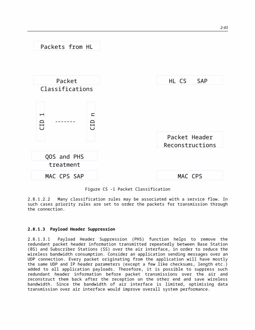
2-55
satellite receiver’s noise temperature.
2.11.2.7.1.2.7 In order to establish power limits for AeroMACS base station transmitters and to avoid interference with the Globalstar uplinks, the AeroMACS base stations with sector antenna transmitters were modelled at 6207 airports in the United States, Europe and the rest of the world. The following assumptions have been applied related to large, medium and small size category airports:
Large size airports:o US categories: 35 Operational Evolution Partnership airports (OEP 35) o Europe: 50 largest European airports according to Wikipedia list
Medium size airports:o 123 US category Class C airportso Europe: 50 medium category airports according to Wikipedia list rank 51 to 100
Small size airports:o All other airports in Openflights database
2.11.2.7.1.2.8 Propose deleting them from above text section and possibly, Also a comment received was that maybe we do not need to provide so much details for this simulation and maybe an alternative would be to reduce the text and provide a reference to the NASA study as well as a to other similar analysis, i.e in SESAR>
2.11.2.7.1.2.9 In the model used in the investigations, each large airport is assigned six 120° sector antennas, each medium airports is assigned three 120° sector antennas and each small airport is assigned one 120° sector antenna. Several simulation runs were applied with different random antenna directions. This is equivalent to assume horizontal omnidirectional station pattern as a mean.
2.11.2.7.1.2.10 The simulations assumed that large airports will use all eleven 5 MHz channels, medium airports will use six 5 MHz channels and small airports will use one 5 MHz channel. Small airports are only allowed transmitting half as much power per sector as the medium and large airports. This takes into account that at smaller sites it is expected that AeroMACS is not permanently running.
2.11.2.7.1.2.11 Finally the following assumptions for EIRP, MIMO system and antenna pattern have been applied:
Effective isotropic Radiated Power (EIRP) is the sector transmit power at the antenna input plus antenna gain,
Maximum allowable EIRP in a base station sector shall be the sum of both transmit power amplifiers in a 2-channel MIMO system,
Base Station Sector patterns are defined to be ITU-R-F-1336-2 reference patterns with 120° 3 dB beam width toward Horizon (see Error: Reference source not found).
2.11.2.7.1.2.12 Based on the simulations, the analysis concluded that under the assumptions considered the AeroMACS deployment will be meeting the ITU WRC2007 requirements, when the worldwide deployment of AeroMACS base stations observe the following emissions limitations:
a)The total base station EIRP in a sector must not exceed: 39.4 dBm for elevation angles up to 1.5 degrees 39.4 dBm linearly decreasing (in dB) to 24.4 dBm for elevation angles from 1.5 to 7.5 degrees 24.4 dBm linearly decreasing (in dB) to 19.4 dBm for elevation angles from 7.5 to 27.5 degrees 19.4 dBm linearly decreasing (in dB) to 11.4 dBm for elevation angles from 27.5 to 90 degrees
b) The total mobile station EIRP shall not exceed 30 dBm
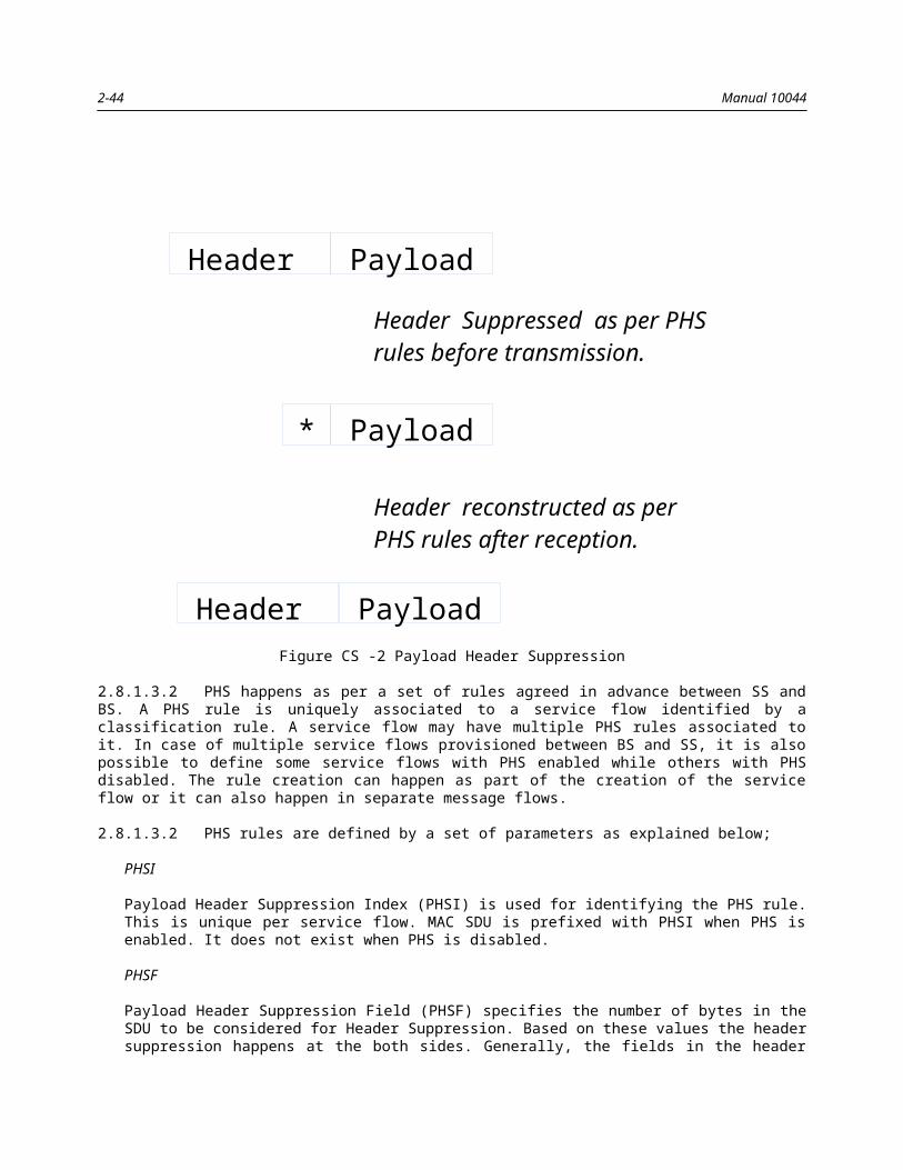
2-56 Manual 10044
Note: The above ground antenna elevation pattern is contained in ITU-R F.1336-2.<Consider deleting all yellow highlighted text below>These limitations were derived under the following assumptions:
(a) EIRP is defined as antenna gain in a specified elevation direction plus the average AeroMACS transmitter power. While the instantaneous peak power from a given transmitter can exceed that level when all of the subcarriers randomly align in phase, when the large number of transmitters assumed in the analysis is taken into account, average power is the appropriate metric.
(b) The breakpoints in the base station EIRP mask are consistent with the elevation pattern of a +15 dBi peak, 120 degree sector antenna as contained in ITU-R F.1336-2.
(c)(c) If a station sector contains multiple transmit antennas on the same frequency (e.g., MIMO), the specified power limit is the sum of the power from each antenna.
(d) No base station antenna down-tilt is applied in these assumptions. Higher sector average transmit power can meet these limitations if antenna pattern down-tilt is used.
(e) Mobile station EIRP is based on full occupancy of transmit sub-carriers for 5 MHz bandwidth
2.11..2.7.1.2.13 The antenna pattern identified in the above analysis is one that has been shown via simulations that meets the WRC2007 requirements. However it is not specified or recommended to be included in chapter 4 as other patterns may also be suitable.
2.11.2.7.1.2.14 The information in this section aims to raise the awareness of the AeroMACS implementers that in eventual dense (end-state) AeroMACS deployment, the antenna pattern of the (ground) base stations and the antenna tilt need to be carefully considered to avoid impact to FSS systems and to continue meeting any applicable ITU requirement.
2.11.2.7.1.2.15 However, this issue (minimization of impact to FSS) cannot be addressed locally at the level of a single airport or in one region only, as it the global and aggregate interference impact that is important.
2.11.2.7.1.2.16 In order to minimize impact to FSS, it is also important that particularly in case of smaller airports, potentially using a limited number of channels, the choice of the channels is spread among different airports to avoid some channels being over assigned (and over used) while others being under assigned (and under used).
2.11.3. Antennae/MIMO
2.11.3.1 Multiple-Input Multiple-Output (MIMO) is a system with plural antennas to improve the system coverage or throughput [1].
2.11.3.2 There are two types of MIMO mode. One is MIMO matrix A (MIMO-A), the other is MIMO matrix B (MIMO-B). MIMO-A employs two transmitting (Tx) antennas and one or two receiving (Rx) antenna to improve coverage by sending the same data via Tx antennas and combining them at the receiver. MIMO-A can be implemented in onboard MS with only one receive antenna.

2-57
2.11.3.3 On the other hand, MIMO-B employs two Tx antennas and two Rx antennas to increase throughput by dividing a single data stream and sending the resulting streams over two antennae in in parallel.
2.11.3.4 AeroMACS Should support downlink MIMO-A .
Note: When applications demand the greater throughput provided by MIMO-B, this may be considered for aircraft.
2.11.3.5 MS installed on ground vehicles or other use cases except for aircraft is recommended to support both MIMO-A and MIMO-B to obtain better throughput.
2.11.3.6 BSs are recommended to support both MIMO-A and MIMO-B. BS will accept many MSs with various types of MIMO mode simultaneously. MIMO-B is available only when both BS and MS support it.
2.12 SENSITIVITY
2.12.1 The sensitivity level is defined as the power level measured at the receiver input when the BER is equal to 1*10-6 ;
2.12.2 The computation of the sensitivity level for the AeroMACS system is based on the following formula:
Where:
* -114: is the thermal noise power term in dBm, referred to 1 MHz Bandwidth and 300 K temperature
* SNRRX: is the receiver SNR , it can be defined as the SNR necessary , at the demodulator input, to get the desired BER for the given modulation and coding rate.
* R : is the repetition factor
* Fs: is the sampling frequency in Hz
* NFFT: is the FFT size
* Nused: is the number of subcarrier used (FFT size – Number of guard band subcarriers – DC carrier)
* ImpLoss: is the implementation loss, which includes non-ideal receiver effects such as channel estimation errors, tracking errors, quantization errors, and phase noise. The assumed value is 5 dB.
NF: is the receiver noise figure, referenced to the antenna port. The assumed value is 8 dB

2-58 Manual 10044
2.12.3 The SNRrx depends on the modulation and coding scheme selected ( a QPSK ½ needs a lower SNR than a 64 QAM ¾ to get the same BER); in case of Convolutional Coding the values defined are:
Receiver SNRModulation Coding Receiver SNR (dB)
QPSK 1/2 5QPSK 3/4 8
16-QAM 1/2 10.516-QAM 3/4 1464-QAM 1/2 1664-QAM 2/3 1864-QAM 3/4 20
Table 1 - Receiver SNR
2.12.4 Using the above parameters in the formula (1) we get the sensitivity values listed in Table 9
Modulation Scheme Rep. Factor Sensitivity64-QAM 3/4 1 -76.37 dBm64-QAM 2/3 1 -78.37 dBm16-QAM 3/4 1 -82.37 dBm16-QAM 1/2 1 -85.87 dBmQPSK 3/4 1 -88.37 dBmQPSK 1/2 1 -91.37 dBmQPSK 1/2 2 -94.37 dBm
Table 2 – AeroMACS Receiver Sensitivities : Rss
_____________________
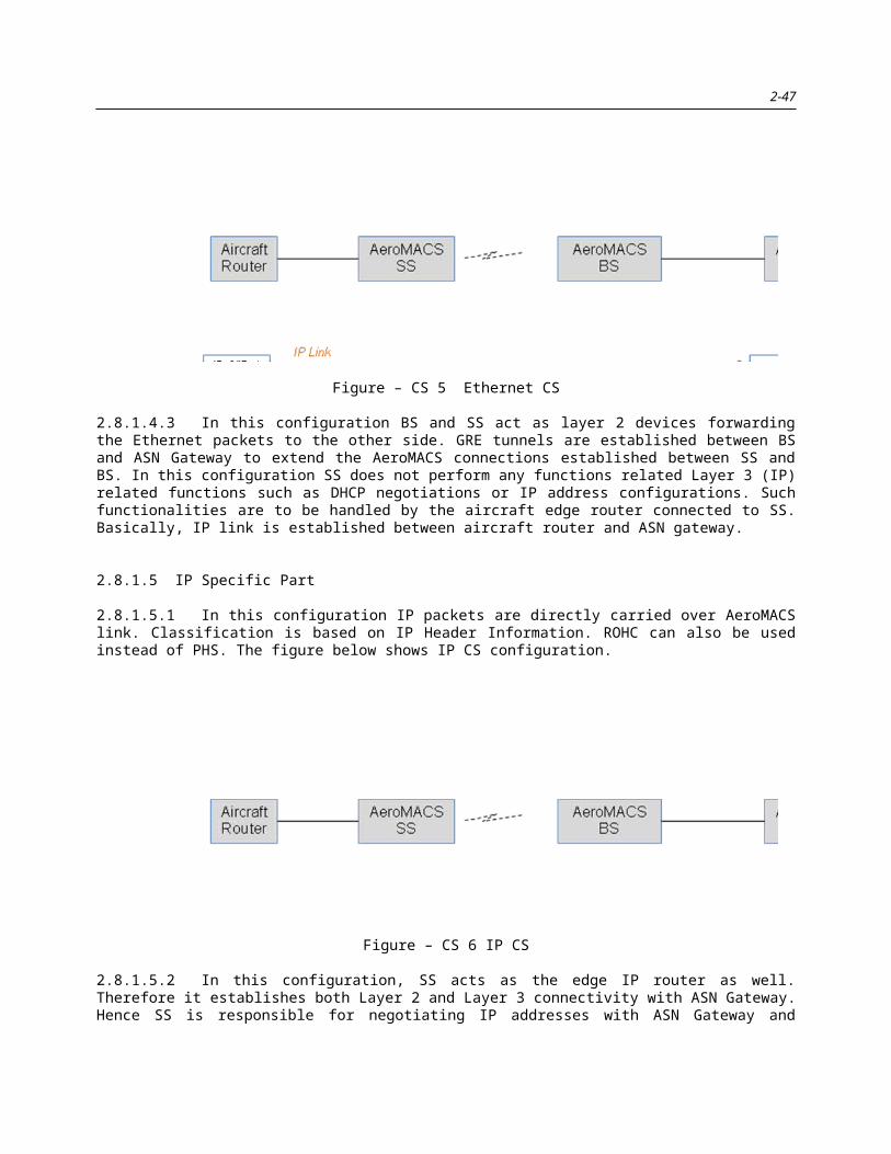
Chapter 3
TECHNICAL SPECIFICATIONS
3.1 SYSTEM ARCHITECTURE
3.1.1 AeroMACS Reference Network
3.1.1.1 SS, ASN and CSN functions MAY be realized in single physical entities. As an alternative approach, SS, ASN and CSN functions MAY be distributed over multiple physical entities.
3.1.2 Subscriber Station and Base Station Definition
3.1.2.1 A BS may host one or more access functions.
3.1.2.2 Connectivity (ie: reachability) of a single BS to maore than on ASN-GW may be required as a redundancy option.
3.1.3 ASN Gateway Definition
3.1.3.1 THe ASNGW may also perform Bearer Plane routing or bridging function.
3.1.3.2 The ASN-GW implementation may include redundancy and load-balancing based on radio parameters, among several ASN-GWs.
3.1.3.3 The ASN-GW implementation may include load-balancing based on SLA requirements of the SSs. For every SS, a BS is associated with exactly one default ASN GW.
Note: The implementation details are out of scope for this document.
3.1.3.4 IP Packets coming from ATS applications shall make use of the IP header field “DSCP” (IPv6 packets have the DSCP value within the “Traffic Class” field of the header).
3.1.3.5 Neither the ASN-GW nor the Access Router shall drop IP packets with a non-zero DSCP field.
3.1.3.6 IP packets shall be queued in case of congestion and according to the different priorities (RFC 4594 gives a recommendation on service categorisation).
3.1.4 AeroMACS ASN Profile
3.1.4.1 AeroMACS ASN Shall support WiMAX Forum profile C as described below.
3.1.5 AAA Proxy/Server
3.1.5.1 The AeroMACS CSN of the home NASP shall distribute the subscirber’s profile to the NAP directly or via the visited NSP.
3-1

3-2 Manual XXXXX
NOTE: One of the main roles of the AAA server within the CSN is to gather the access information of all AeroMACS users.
3.1.5.2 The ASN-GW should support and implement a RADIUS client.
NOTE: BSs are not end-points in RADIUS and therefore do not implement the RADIUS protocol.
3.1.6 DCHP Server
3.1.6.1 The IP address allocated to an MS may be public or private.
3.1.6.2 The IP address allocated to an MS may either be a point-of-attachment IP address or an inner-tunnel IP address.
3.1.7 Network Architecture
3.1.7.1 Network Deployment Models.
3.1.7.1.1 AeroMACS shall support multiple NSPs for provisioning ATC/AOC services over the same data link. AeroMACS infrastructure shall provide the capability to the subscriber to select the preferred CSN/NSP.
3.1.7.2 Definition of actors (H-NSP, V-NSP, NAP)
3.1.7.2.1 The typical airport communication infrastructure: Shall support terminal datalink applications Shall offer connectivirty to the global ASNP network and Shall provide dynamic mobile connectivity to aircraft.
3.1.8 AeroMACS Profile
3.1.8.1 An MS SHOULD have a list of NSPs loaded in its configuration.
NOTE: Please refer to section 4.1 of Error: Reference source not found for a detailed description of NET entry discovery and selection.
3.1.8.2 The most significant 24 bits (MSB 24 bits) of the “Base Station ID” SHALL be used as Operator ID, which is the NAP Identifier.
NOTE: NAP discovery is based on the procedures defined in IEEE 802.16 standard Error: Reference source not found and out of the scope of this specification. Operator ID/NAP ID allocation and administration method are managed by IEEE Registration authority, which defines the range for global IDs assigned by IEEE and the range for MCC/MNC IDs which can also be used. The field formatting is defined in IEEE 802.16 standard.
3.1.8.3 In the NAP and NSP deployment case where there is only one NSP associated with the NAP and where no regulatory or deployment reasons justify separate presentation of an NSP identifier, the NAP SHALL set the NSP Identifier Flag to a value of ‘0’.
NOTE: In this case, when the MS detects the identifier of a NAP, the MS knows the identifier of associated NSP.
3.1.8.4 The MS MAY continue NSP discovery to obtain a verbose NSP name. NSP ID is formatted as a 24-bit field that follows the format shown in Table 3.

Appendix 10. Guidelines on the Internet to be obtained from CNS after ANC review A10-3

3-4 Manual XXXXX
Table 3: NSP ID format [32]
3.1.8.4 In the authentication process described in section 4.1.2.4 of Error: Reference source not found, the MS MAY format the NAI (Network Access Identifier) used as an outer identity during EAP exchanges as follows:<routing realms><WiMAX decoration><username>@<realm> where:
Routing realms: Optionally used. The use of routing realm is described by RFC 4282. Example: [email protected]
WiMAX decoration: Optionally used to indicate various MS capability/intent. The WiMAX decoration is extensible. The WiMAX decoration consists of one or more attribute value pairs (avp) separated by the “|”enclosed within curly braces.
“{“ avp1 “|” avp2 ….“}” where an avp is formatted as: name“=”value with no spaces before and immediately after the “=”. The character set used for name and value must be consistent with the character set specified by RFC 4282. The name must be alphanumeric with no spaces. Example: {fm=1|xm=3}[email protected]. Currently there is no specific avp defined.
3.1.8.5 When an aircraft (MS) lands and scans the AeroMACS band, it SHALL select a NAP, and then the NSP.
NOTE 1: The way/order in which the channels are scanned and the way the preferred NAP is selected are implementation-dependent. The NAP (operator) selection can rely on the following criteria:
Preferred operator (if commercial) NSP support (especially the ability to support ATC flows and other needed flows, AOC at least)
NOTE 2: The procedure for NAP selection can be as follows:1. Select a NAP who is providing Aircraft connectivity.2. Select a NAP who is contracted (might not be compulsory for ATC traffic only).3. Select the preferred NAP if several are possible (based on airline preferences).4. Select a NAP who can provide ATC connectivity up to H-NSP.5. Select a NAP who can authenticate the aircraft (by relaying the AAA requests to the H-NSP).
3.1.8.6 The previous procedure can be satisfied either by: a) analysing the Operator ID (that would be encoded in a specific way), or b) pre-determining channel values/operator IDs in a local aircraft configuration file, or c) analysing the NSP IDs supported by the NAP and select the NAP depending on the NSP ID.
3.1.8.7 It is proposed to define a way to encode the Operator IDs in order to identify ICAO and aircraft-connectivity operators - same proposal for NSP ID – (however, it might be difficult to get a range of IDs from IEEE). Either way, the MS will need to have locally allowed Operator ID values, allowed channels depending on the location, H-NSP ID and associated realm.
3.1.8.8. The MS can use the H-NSP realm as <routing realm> in authentication process.
3.1.8.9 The ASN can use the H-NSP realm as <routing realm> to route to the proper NSP.
3.1.8.10 The procedures articulated in this note are guidelines for the implementation of NAP/NSP selection algorithms. However, since they are not standardized, the final solution relies on the decision made during system deployment.

Appendix 10. Guidelines on the Internet to be obtained from CNS after ANC review A10-5
3.1.9 Roaming Scenatrios
3.1.9.1 Roaming between NSPs SHALL not be precluded.
3.1.9.2 A single NAP MAY serve multiple MSs using different private and public IP domains owned by different NSPs.
3.1.9.3 A visited NSP MAY have roaming contractual relationship with the subscriber’s home NSP.
NOTE: The AAA framework in this scenario behaves as described in the corresponding section above, with the Visited NSP providing AAA traffic routing to the home AAA server with means to guarantee the confidentiality and safety of the procedure. The local AAA server can act as an AAA proxy when the network entry process of AeroMACS is triggered.
3.1.10 Mobility
3.1.10.1 Mobile UPv6 shall be implemented by a mobilitiy Service Provider (NSP) in compliance with the ICAO Doc. 9896 standard for communication with aircraft.
3.1.10.2 A Home Agent (HA) SHALL be required at the home network.
3.1.10.3 A secure communication path (e.g. private network tunnel) between ASN-GW to the NSP HA SHALL be required.
NOTE: In the visited network, Foreign Agent (FA) or Access Router (AR) stores information of aircraft visiting the network, gives a local IP to the visiting aircraft and advertises the so called “care of address” to the HA in order to allow re-routing of AeroMACS datagrams addressed to the MS in the Access Network where it is currently attached.
3.1.10.4 To complete the support of a moving aircraft into a visited ASN, the MSs SHALL integrate a MIP client.
NOTE: MIP suffers from several drawbacks. The main concern would be the big delay that tunneling between HA and FA/AR introduces. Especially sensitive applications, such as real time, would be affected by this. See Section Error: Reference source not found Deployment Models for suggested solutions to optimize routes in a MIP architecture.
3.1.11 IP Address Configuration
3.1.11.1 AeroMACS infrastructure SHALL give support to network addressing for vehicles and aircraft in the home and visited networks without distinction.
3.1.11.2 AeroMACS SHALL use IP radio and ground Internet Protocol (IP) compliant with ICAO 9896 Error: Reference source not found.
3.1.11.3 AeroMACS SHALL support IPv6.
NOTE 1: AeroMACS implements IPv6 addressing architecture as specified in RFC 4291 and uses globally scoped IPv6 addresses.
NOTE 2: ATN/IPS MSPs containing AeroMACS networks obtain IPv6 address prefix assignments from their local Internet registry (LIR) or regional Internet registry (RIR).
NOTE 3: MSPs obtain a /32 IPv6 address prefix assignment for the exclusive use of AeroMACS MS. MSPs advertise their /32 aggregate prefix to the ATN/IPS.

3-6 Manual XXXXX
3.1.11.4 AeroMACS SHALL support IPv4.
NOTE 1: Support of IPv4 is required in order to be interoperable with legacy systems.
NOTE 2: ASN routers support dual network layer stack, tunneling or protocol conversion, as specified in ICAO Doc 9896, for connecting IPv6 core networks to AeroMACS ASN network which can implement IPv4 stack.
3.1.11.5 AeroMACS infrastructure SHALL give support to network addressing for vehicles and aircraft in the home and visited networks without distinction.
3.1.11.6 Mobile IPv6 SHALL be implemented by a Mobility Service Provider (MSP) in compliance with ICAO 9896 standard for communication with aircraft.
3.1.11.7 A MS SHALL get a dynamic IP address.
3.1.11.8 The vehicles which have been allocated the same address SHALL not operate on the same aerodrome.
3.1.11.9 AeroMACS SHALL support multiple NSPs for provisioning ATC/AOC services over the same data link.
3.1.11.10 AeroMACS infrastructure SHALL provide the capability to the subscriber to select the preferred CSN/NSP.
3.1.11.11 ASN-GW SHALL support GRE tunnelling on R6 interface.
3.1.11.12 The network addresses for the management / control domain of CSN shall be different from the ASN data plane addresses in order to ensure network abstraction.
3.1.11.13 CSN shall maintain site (airport) wise IP address pools for aircraft in corresponding airports to avoid address conflicts.
3.1 PERFORMANCE
3.1.1 Power Levels
The total base station Effective Isotropic Radiated Power (EIRP) in a sector shall not exceed:
a) 39.4 dBm for elevation angles from the horizon up to 1.5 degrees
b) 39.4 dBm linearly decreasing (in dB) to 24.4 dBm for elevation angles from 1.5 to 7.5 degrees
c) 24.4 dBm linearly decreasing (in dB) to 19.4 dBm for elevation angles from 7.5 to 27.5 degrees
d) 19.4 dBm linearly decreasing (in dB) to 11.4 dBm for elevation angles from 27.5 to 90 degrees

Appendix 10. Guidelines on the Internet to be obtained from CNS after ANC review A10-7
In addition the following requirement for the mobile stations is applied:
The total mobile station EIRP shall not exceed 30 dBm
Note 1: EIRP defined as antenna gain in a specified elevation direction plus the average AeroMACS transmitter power. While the instantaneous peak power from a given transmitter may exceed that level when all of the subcarriers randomly align in phase, when the large number of transmitters assumed in the analysis is taken into account, average power is theappropriate metric.
Note 2: The breakpoints in the EIRP mask are consistent with the elevation pattern of a +15 dBi peak, 120 degree sector antenna as contained in ITU-R F.1336-2.
Note 3: These values were derived using the worst-case analysis described. Other approaches involving higher powers may be acceptable, however additional analysis must be performed to ensure the total interference allowable at the FSS satellites, consistent with ITU requirements, is not exceeded.
Note 4: If a sector contains multiple transmit antennas (e.g., MIMO), the specified power limit is the sum of the power from each antenna.
3.1.2 Interference
3.1.2.1 As described in section 3.yyyy, the implementation of AeroMACS needs to be planned in a way that it will minimize the risk for potential interference to FSS. In particular the assignments of the channels and the ground antenna patterns and antenna tilt should be considered.
3.1.2.2 Where antenna tilt is employed, it is highly recommended that site surveys are undertaken to ensure that extraneous reflections do not result in further interference.
3.1.2.3 In order to spread evenly the interference to FSS, the assignment of AeroMACS channels should be distributed uniformly over areas containing several airports.
Note: The above recommendation is particularly relevant for the case of airports not using all AeroMACS channels.
3.1.2.4 It is also recommended that the local AeroMACS implementations (?in conjunction with regional/global bodies????) optimize the ground antenna gain to minimize impact to the FSS services.

3-8 Manual XXXXX
3.2 HAND-OFF
3.3 ROUTING AND DISCOVERY
3.3.1
3.3.2
3.4 SECURITY FRAMEWORK
3.4.1
3.4.2
3.4.4
3.5 PRIORITIZATION
3.6 UPPER LAYER INTERFACES
3.7 System Management
3.7.1 AeroMACS SHALL support the necessary Network Management services (NET) as required by the supported safety of life and flight regularity services.
3.7.2 System monitoring SHALL be performed by organizations which operate the AeroMACS system or components.
3.7.3 The performance monitoring and system supervision capabilities of the AeroMACS SHALL NOT impede the operation of the AeroMACS system.
3.7.4 The ground system SHALL be capable of detecting ground system failures and configuration changes that would cause the communication service to no longer meet the requirements for the intended function.
3.7.5 When the communication service no longer meets the requirements for the intended function, the ground system SHALL support notification capability.

Appendix 10. Guidelines on the Internet to be obtained from CNS after ANC review A10-9
3.8 FREQUENCY ALLOCATION/CHANNELISATION
3.8.1 RF Profile for AeroMACS
3.8.1.1 Table 1 provides the set of RF channel center frequency numbers for the AeroMACS Band Class Group. RF channel center frequencies can be derived as a function of RF channel center frequency numbers (fcN) using the following equation.
fc = 0.05*fcN
The RF channel center frequency (fc) is in MHz.
In Table 1, the RF Channel Center Frequency Number Set is specified using the following three parameters:
( fcNstart, fcNstop, step)
3.8.1.2 Where fcNstart is the starting RF channel center frequency number assigned to the first RF channel center frequency, fcNstop is the ending RF channel center frequency number assigned to the last RF channel center frequency, and step is the RF channel center frequency number step size between fcNstart and fcNstop.
Table 1. AeroMACS Channel Set Definition.
Band Class Group
Channel BW (MHz)
Frequency Range (MHz) RF Channel Center Frequency Number SetUplink Downlink Uplink Downlink
10.A 5 5000-5150 5000-5150 (100050, 102950, 5) (100050, 102950, 5)
3.8.1.3 The AeroMACS center frequency step size is 250 KHz consistent with WiMAX Forum® Air Interface Release 1.0. Standard AeroMACS RF channels are every 250 KHz from a channel center frequency of 5002.5 MHz to 5147.5 MHz.
3.8.2 AeroMACS Band Class Group
3.8.2.1 WiMAX Forum® Mobile Radio specifications for Mobile Stations and Base Stations for AeroMACS are listed in Table 2.
Table 2. AeroMACS Band Class Group and Primary Characteristics
Band Class Group
Uplink MS Transmit Frequency (MHz)
Downlink MS Receive Frequency (MHz)
Channel BW (MHz)
Duplex Mode
WiMAX Forum® Air Interface Release
10.A 5000-5150 5000-5150 5 TDD 1.0
3.8.3 Preferred Channel Center Frequencies for AeroMACS
3.8.3.1 The RF channel center frequencies of Table 3 represent preferred channels for AeroMACS. Compliance to this list is not sufficient for conformance. The RF channel center frequencies listed in Table 2 are the basis for interoperability and conformance purposes.

3-10 Manual XXXXX
Table 3. AeroMACS Preferred Channel Set Definition.
Band Class Group
Channel BW (MHz)
Frequency Range (MHz) RF Channel Center Frequency Number SetUplink Downlink Uplink Downlink
10.A 5 5000-5150 5000-5150 (100100, 102900, 100)
(100100, 102900, 100)
3.8.3.2 Preferred AeroMACS RF channels are every 5 MHz from a channel center frequency of 5005 MHz to 5145 MHz.
— END —

APPENDIX A – Test Procedure for Spectral Mask and Emissions.
A.1 Introduction
The purpose of this test is to verify compliance of the spectral mask and emissions requirements as required by the SARPs standard.BS/MS shall transmit signals without unwanted emissions in the frequency range immediately outside the necessary bandwidth to avoid interference to other frequency bands or systems.
A.2 General Information
A2.1 References
[1] ITU-R SM.329-12 (2012-09)
A2.2 Abbreviations
BS: Base StationBSE: Base Station EmulatorMS: Mobile StationRBW: Resolution Band Width SARPs: Standards And Recommended Practices UUT: Unit Under TestWiMAX: Worldwide Interoperability for Microwave Access
A.3 Definition of the spectral emission mask and the zero dB reference
A3.1 The power spectral density of the emissions when all active sub carriers are transmitted in the channel shall be attenuated below the maximum power spectral density as follows:
a) On any frequency removed from the assigned frequency between 50–55% of the authorized bandwidth: 26 + 145 log (% of BW/50) dB
b) On any frequency removed from the assigned frequency between 55– 100% of the authorized bandwidth: 32 + 31 log (% of (BW)/55) dB
c) On any frequency removed from the assigned frequency between 100– 150% of the authorized bandwidth: 40 +57 log (% of (BW)/100) dB
d) On any frequency removed from the assigned frequency beyond 150% of the authorized bandwidth: 50 dB
Note. The power spectral density at a given frequency is the power within a bandwidth equal to a 100 kHz centered at this frequency, divided by this measurement bandwidth. Further, the measurement of the power spectral density should encompass the energy over at least one frame period.
A3.2 The zero dB reference of the spectral mask shall be the peak power spectral density in the assigned channel bandwidth of 5 MHz.
3-1

3-2 Manual XXXXX
A.4 Test Setup
A4.1 The test setup below is considered for the Spectral Mask test. Figures 1 and 2 show examples of BS/MS testing setup.
Figure 1. BS test setup
Figure 2. MS test setupA.4.2 Test Procedure
A4.2.1 Initialization:1) Set up the test environment for the UUT.2) Configure the spectrum analyzer in accordance with Table 1.
Note. Although the resolution bandwidth (RBW) is set to 100 kHz, the RBW can be set to 10 kHz or a smaller value than 100 kHz to improve measurement accuracy for a narrow region where the variation of the power is large, such as a) range defined in Paragraph 3. Refer to Paragraph 7 for the details.
Table 1. Conditions for spectrum analyzerItems RBW=100kHz RBW=10kHz
Center FrequencySpanResolution Band WidthVideo Band WidthSweep Time
Detector
Center frequency of UUT.25 MHz100 kHz100 kHzAll the measurement of the power spectral density should encompass the energy over at least one frame period. (Positive) Peak
Center frequency of UUT.25 MHz10 kHz10 kHzAll the measurement of the power spectral density should encompass the energy over at least one frame period. (Positive) Peak
3) Turn UUT power on.
SignalingUnit (BSE)
Attenuator
Spectrum Analyzer
MSUUT
Attenuator
Spectrum Analyzer
BSUUT

Appendix 10. Guidelines on the Internet to be obtained from CNS after ANC review A10-3
4) Set a frequency to UUT.
A4.2.2 Test Procedure:
Step P-1. Transmit signal using all active sub carriers at maximum power. Step P-2. Start to sweep the transmit power on the spectrum analyzer. Step P-3. Save the sweeping data as the test result. Step P-4. Take the peak value of the test result as 0 dB reference. Step P-5. Align the top of the spectral mask to 0 dB reference, and compare the spectral mask
and the test result. Step P-6. Repeat Step P-1 through P-5 at least for Low, Mid and High frequencies supported
by the UUT. Step P-7. End of test.
A4.2.3 Compliance Requirements
A4.2.3.1 Pass verdict:
At all frequencies, test result read in P-5 is not higher than the spectral mask.
A4.2.3.2 Fail verdict:
At any frequencies, test result read in P-5 is higher the spectral mask.
A4.3 Supplemental Information
In ITU-R [1] the procedures is described the following: ----------------------------------------------------------------------------------------------------------------------------------Annex2 Methods of measurement of spurious domain emissions, 1.1.2 Resolution bandwidths
A4.4.1 As a general guideline, the resolution bandwidths (measured at the -3 dB points of the final IF filter) of the measuring receiver should be equal to the reference bandwidths as given in recommendations 4.1. To improve measurement accuracy, sensitivity and efficiency, the resolution bandwidth can be different from the reference bandwidth. For instance, narrower resolution bandwidth is sometimes necessary for emissions close to the centre frequency. When the resolution bandwidth is smaller than the reference bandwidth, the result should be integrated over the reference bandwidth (the integration should be made on the basis of a power sum unless the spurious signal is known to be additive in voltage or with intermediate law, see Note 1).
----------------------------------------------------------------------------------------------------------------------------------
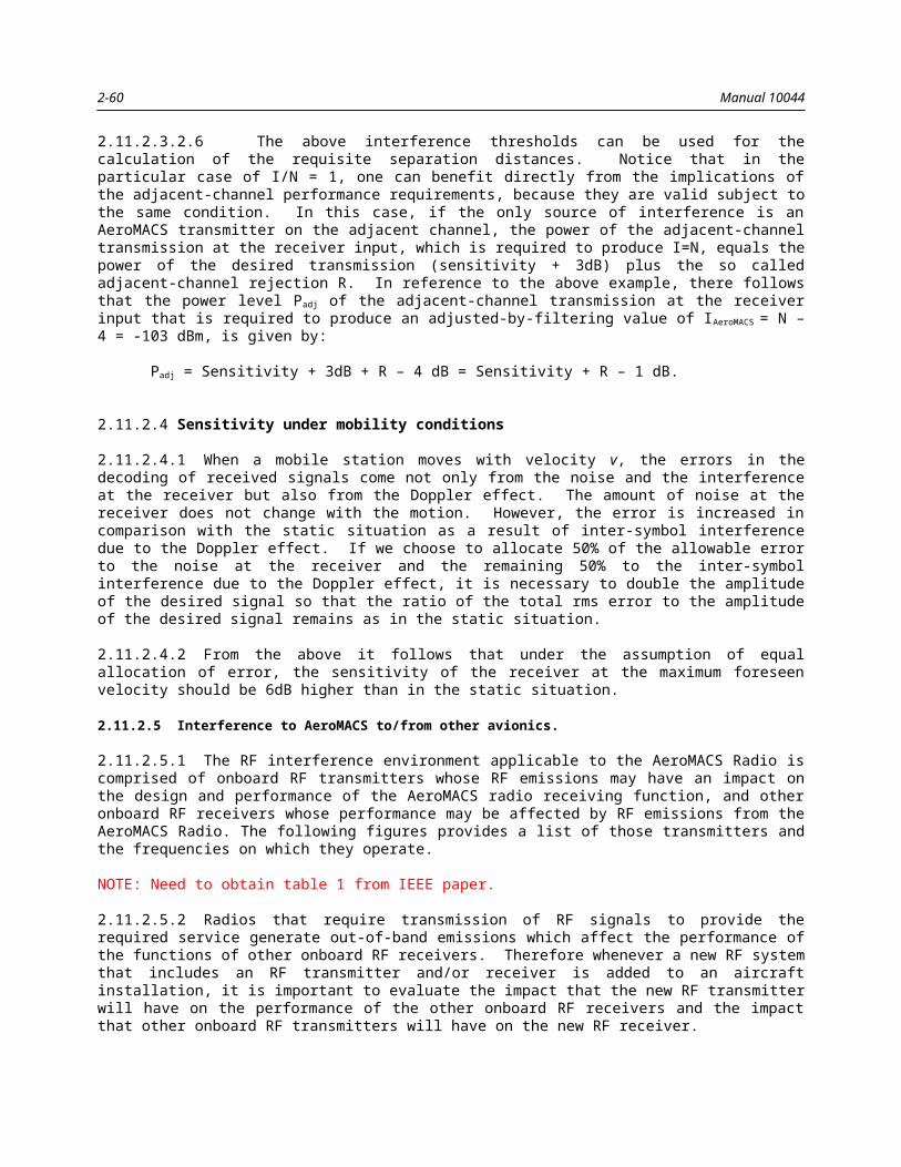
3-4 Manual XXXXX
A4.4.2 RBW is the equivalent bandwidth to that of the IF filter being equipped in the spectrum analyzer, and due to the characteristic of the IF filter, the signal (power) outside the band may be detected and displayed as a spectrum. In order to reduce this undesired detection, it is necessary to narrow the RBW and thus increase the frequency resolution. However, a too narrow RBW will lead to an excessively long sweep time which is a tradeoff worth, so it is necessary to pay sufficient attention to.
A4.4.3 When measuring signals with steep spectrums such as OFDM, failure to take a sufficient frequency resolution will incur considerable stretching to the spectrum contour
A4.4.4 More specifically, even when the RBW is configured to 100 kHz, the power beyond 100 kHz can pass through depending on filter characteristics as a result, and the power beyond 100 kHz is also undesirably integrated and reflected in the test result. (Figure 3)
A4.4.5 In order to mitigate the impact from filter characteristics and improve the measurement accuracy in those areas with steep spectrum, it is preferable to set the RBW narrower, according to the stipulations of the ITU-R.
Figure 3 Filter Frequency Response
A4.4.6 Moreover, since the subcarrier interval for AeroMACS is defined as 10.94 kHz, a RBW of 10 kHz can make the measurement accurate enough in terms of frequency domain; however, after the RBW is reduced, captured data needs to be integrated over 100 kHz. It is also necessary to properly increase the measuring period to avoid loss of opportunities for detecting peaks due to the reduction of the RBW.
Expected value = 3dB BW
Actual integrated value
3dB

![Jaba Satcom S.A. de C.V. - [ VoIP Satelital ] Telefonia … Satcom S.A. de C.V. [ Ingeniería SatCom ] [ RF Technology ] [ Interoperability ] [ AeroSpace] [Comunicaciones ] [ Telefonía](https://img.pdfslide.net/doc/110x75/5ae2fc697f8b9a7b218c85c1/jaba-satcom-sa-de-cv-voip-satelital-telefonia-satcom-sa-de-cv.jpg)


![Jaba Satcom S.A. de C.V. - Telefonos Satelitales · Jaba Satcom S.A. de C.V. [ Ingeniería SatCom ] [ RF Technology ] [ Interoperability ] [ AeroSpace] [Comunicaciones ] [ Telefonía](https://img.pdfslide.net/doc/110x75/5e86aa1b58f7f502e224fe33/jaba-satcom-sa-de-cv-telefonos-satelitales-jaba-satcom-sa-de-cv-ingeniera.jpg)


![Satcom Overview[1]](https://img.pdfslide.net/doc/110x75/577d23ae1a28ab4e1e9a7a50/satcom-overview1.jpg)