Embed Size (px)
Citation preview
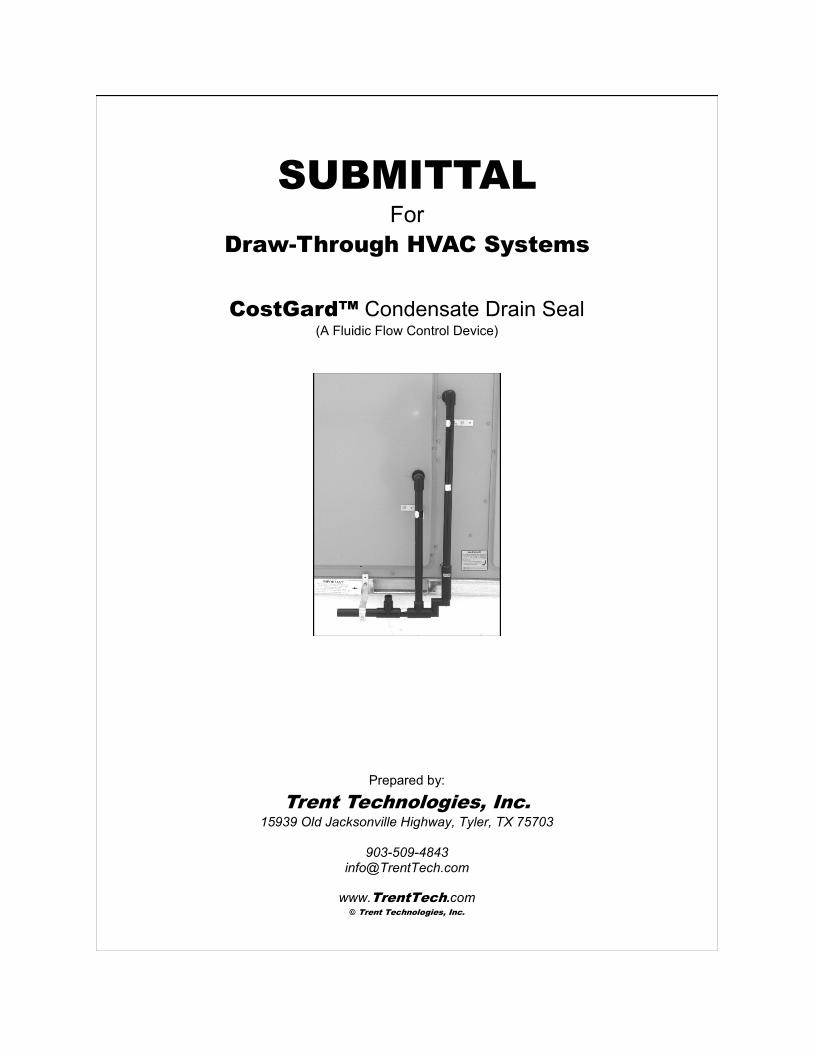
SUBMITTAL
For
Draw-Through HVAC Systems
CostGard™ Condensate Drain Seal (A Fluidic Flow Control Device)
Prepared by:
Trent Technologies, Inc.
15939 Old Jacksonville Highway, Tyler, TX 75703
903-509-4843 [email protected]
www.TrentTech.com © Trent Technologies, Inc.
GENERAL
The CostGard™ Condensate Drain Seal was developed
specifically to replace the condensate trap on draw-through
HVAC systems. Unlike a condensate trap, it uses an air seal
instead of a water seal and thereby eliminates costly
operational and health related problems needlessly tolerated by
facility managers for more than half a century. It does this by
reducing (1) service calls, (2) maintenance requirements, (3)
damage to equipment, (4) damage to surrounding property, and
(5) threats to healthy indoor air quality.
Operation
The CostGard™ Condensate Drain Seal is the result of over
four years of engineering research and development. It makes
use of the hydraulic and pneumatic forces present in all draw-
through air handlers. It is simple, effective and reliable. It has
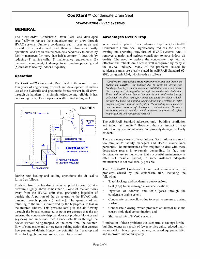
no moving parts. How it operates is illustrated in Figure 1.
Advantages Over a Trap
When used in place of a condensate trap the CostGard™
Condensate Drain Seal significantly reduces the cost of
owning and operating draw-through HVAC systems. And, it
removes a major and serious contributor to poor indoor air
quality. The need to replace the condensate trap with an
effective and reliable drain seal is well recognized by many in
the HVAC industry. Many of the problems caused by
condensate traps are clearly stated in ASHRAE Standard 62-
89R, paragraph 5.6.4, which reads as follows:
CostGard™ Condensate Drain Seal for
DRAW-THROUGH HVAC SYSTEMS
FIGURE 1
“Condensate traps exhibit many failure modes that can impact on
indoor air quality. Trap failures due to freeze-up, drying out,
breakage, blockage, and/or improper installation can compromise
the seal against air ingestion through the condensate drain line.
Traps with insufficient height between the inlet and outlet [design
deficiency] on draw-through systems can cause the drain to back-
up when the fan is on, possibly causing drain pan overflow or water
droplet carryover into the duct system. The resulting moist surfaces
can become sources of biological contamination. Seasonal
variations, such as very dry or cold weather, may adversely affect
trap operation and condensate removal.”
Page 2 of 4
During both heating and cooling operations, the air seal is
formed as follows:
Fresh air from the fan discharge is supplied to point (a) at a
pressure slightly above atmospheric. Some of the air flows
away from the HVAC unit; thus, preventing ingestion of
outside air. A portion of the air returns to the HVAC unit,
passing through points (b) and (c). The quantity of air
returning to the unit is minimized by the high-pressure loss in
the mitered elbows. This pressure loss plus the air flowing
through the bypass connected at point (c) ensures that the air
entering the condensate drip pan does not produce blowing and
geysering and an aerosol mist. Condensate flows through the
device without being trapped. At the same time, the counter-
flow of condensate and air creates a pulsing action that ensures
free passage of debris. Hence, the potential for freeze-up and
flow blockage (common problems with traps) is nil.
The ASHRAE Standard addresses only “building ventilation
and indoor air quality.” However, the cost impact of trap
failures on system maintenance and property damage is clearly
evident.
There are many causes of trap failures. Such failures are much
too familiar to facility managers and HVAC maintenance
personnel. The maintenance effort required to deal with these
destructive results is extremely demanding. In fact, trap
deficiencies are so numerous that successful maintenance is
often not feasible. Indeed, in some instances adequate
maintenance is not realistically possible.
The CostGard™ Condensate Drain Seal eliminates all the problems caused by the condensate trap, including the
following:
▪ Trap blockage and condensate pan overflow;
▪ Seal (trap) freeze-damage in outside locations;
▪ Ingestion of odorous and toxic gases through the
condensate drain system;
▪ Condensate pan overflow, due to negative pressure, during
start-up;
▪ Condensate blowing, which produces an aerosol mist and
causes biological contamination; and
▪ Shortened life of HVAC systems.
Elimination of these problems yields enormous savings for the
building owner as a result of fewer service calls, reduced main-
tenance effort, less property damage, increased equipment life,
and improved indoor air quality.
PRODUCTS
The CostGard™ Condensate Drain Seal is produced in two basic model types: Production (P1525) and Custom-built models
(CXXXX). Each is fabricated from polyvinyl chloride (PVC). As a family, these model types are available for a wide range of
draw-through HVAC systems. Specifically, CostGard™ Condensate Drain Seals are available for HVAC systems with widely
differing characteristics:
1. Drain diameters up to 2.0 inches (nominal pipe dimensions);
2. Static pressure in the drain pan = -5.0 inches wc, or less; and
3. Cooling capacities up to 100+ tons.
Production Models (P1525)
The production model type, designated as P1525, is available
in four (4) different models, which can accommodate drain
diameters up to one (1.0) inch and can operate with a negative
static pressure in the drain pan of 1.5 inches wc or less.
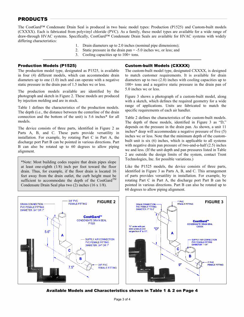
The production models available are identified by the
photograph and sketch in Figure 2. These models are produced
by injection molding and are in stock.
Table 1 defines the characteristics of the production models.
The depth (i.e., the distance between the centerline of the drain
connection and the bottom of the unit) is 5.6 inches* for all
models.
The device consists of three parts, identified in Figure 2 as
Parts A, B, and C. These parts provide versatility in
installation. For example, by rotating Part C in Part A, the
discharge port Part B can be pointed in various directions. Part
B can also be rotated up to 60 degrees to allow piping
alignment.
Custom-built Models (CXXXX)
The custom-built model type, designated CXXXX, is designed
to match customer requirements. It is available for drain
diameters up to two (2.0) inches with cooling capacities up to
100+ tons and a negative static pressure in the drain pan of
5.0 inches wc or less.
Figure 3 shows a photograph of a custom-built model, along
with a sketch, which defines the required geometry for a wide
range of applications. Units are fabricated to match the
specific requirements of each air handler.
Table 2 defines the characteristics of the custom-built models.
The depth of these models, identified in Figure 3 as “D,”
depends on the pressure in the drain pan. As shown, a unit 11
inches* deep will accommodate a negative pressure of five (5)
inches wc or less. Note that the minimum depth of the custom-
built unit is six (6) inches, which is applicable to all systems
with negative drain pan pressure of two-and-a-half (2.5) inches
wc and less. (If the unit depth and pan pressures listed in Table
2 are outside the design limits of the system, contact Trent
Technologies, Inc. for possible variations.)
Like the P1525 models, the device consists of three parts,
identified in Figure 3 as Parts A, B, and C. This arrangement
of parts provides versatility in installation. For example, by
rotating Part C in Part A, the discharge port Part B can be
pointed in various directions. Part B can also be rotated up to
60 degrees to allow piping alignment.
Page 3 of 4
FIGURE 2
Available Models and Characteristics shown in Table 1 & 2 on Page 4
FIGURE 3
*Note: Most building codes require that drain pipes slope
at least one-eighth (1/8) inch per foot toward the floor
drain. Thus, for example, if the floor drain is located 16
feet away from the drain outlet, the curb height must be
sufficient to accommodate the depth of the CostGardTM
Condensate Drain Seal plus two (2) inches (16 x 1/8).
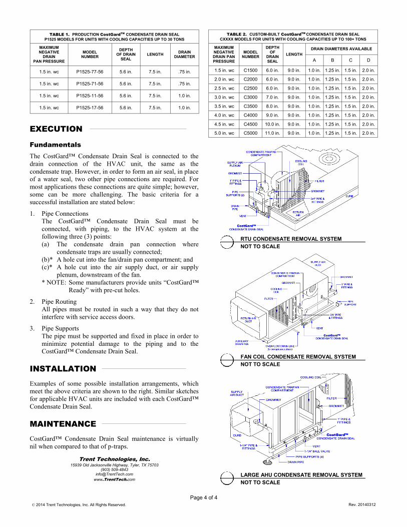
TABLE 1. PRODUCTION CostGardTM
CONDENSATE DRAIN SEAL
P1525 MODELS FOR UNITS WITH COOLING CAPACITIES UP TO 30 TONS
MAXIMUM NEGATIVE
DRAIN PAN PRESSURE
MODEL NUMBER
LENGTH DRAIN
DIAMETER
DEPTH OF DRAIN
SEAL
1.5 in. wc P1525-77-56 7.5 in. .75 in. 5.6 in.
1.5 in. wc P1525-71-56 7.5 in. .75 in. 5.6 in.
1.5 in. wc P1525-11-56 7.5 in. 1.0 in. 5.6 in.
1.5 in. wc P1525-17-56 7.5 in. 1.0 in. 5.6 in.
Page 4 of 4
EXECUTION
Fundamentals
The CostGard™ Condensate Drain Seal is connected to the
drain connection of the HVAC unit, the same as the
condensate trap. However, in order to form an air seal, in place
of a water seal, two other pipe connections are required. For
most applications these connections are quite simple; however,
some can be more challenging. The basic criteria for a
successful installation are stated below:
1. Pipe Connections
The CostGard™ Condensate Drain Seal must be
connected, with piping, to the HVAC system at the
following three (3) points:
(a) The condensate drain pan connection where
condensate traps are usually connected;
(b)* A hole cut into the fan/drain pan compartment; and
(c)* A hole cut into the air supply duct, or air supply
plenum, downstream of the fan.
* NOTE: Some manufacturers provide units “CostGard™
Ready” with pre-cut holes.
2. Pipe Routing
All pipes must be routed in such a way that they do not
interfere with service access doors.
3. Pipe Supports
The pipe must be supported and fixed in place in order to
minimize potential damage to the piping and to the
CostGard™ Condensate Drain Seal.
INSTALLATION
Examples of some possible installation arrangements, which
meet the above criteria are shown to the right. Similar sketches
for applicable HVAC units are included with each CostGard™
Condensate Drain Seal.
MAINTENANCE
CostGard™ Condensate Drain Seal maintenance is virtually
nil when compared to that of p-traps.
Trent Technologies, Inc.
15939 Old Jacksonville Highway, Tyler, TX 75703 (903) 509-4843
www.TrentTech.com
Rev. 20140312
TABLE 2. CUSTOM-BUILT CostGardTM CONDENSATE DRAIN SEAL
CXXXX MODELS FOR UNITS WITH COOLING CAPACITIES UP TO 100+ TONS
MAXIMUM NEGATIVE DRAIN PAN PRESSURE
MODEL NUMBER
DEPTH OF
DRAIN SEAL
DRAIN DIAMETERS AVAILABLE
LENGTH
A B C D
1.5 in. wc C1500 6.0 in. 9.0 in. 1.0 in. 1.25 in. 1.5 in. 2.0 in.
2.0 in. wc C2000 6.0 in. 9.0 in. 1.0 in. 1.25 in. 1.5 in. 2.0 in.
2.5 in. wc C2500 6.0 in. 9.0 in. 1.0 in. 1.25 in. 1.5 in. 2.0 in.
3.0 in. wc C3000 7.0 in. 9.0 in. 1.0 in. 1.25 in. 1.5 in. 2.0 in.
3.5 in. wc C3500 8.0 in. 9.0 in. 1.0 in. 1.25 in. 1.5 in. 2.0 in.
4.0 in. wc C4000 9.0 in. 9.0 in. 1.0 in. 1.25 in. 1.5 in. 2.0 in.
4.5 in. wc C4500 10.0 in. 9.0 in. 1.0 in. 1.25 in. 1.5 in. 2.0 in.
5.0 in. wc C5000 11.0 in. 9.0 in. 1.0 in. 1.25 in. 1.5 in. 2.0 in.
RTU CONDENSATE REMOVAL SYSTEM
NOT TO SCALE
LARGE AHU CONDENSATE REMOVAL SYSTEM
NOT TO SCALE
FAN COIL CONDENSATE REMOVAL SYSTEM
NOT TO SCALE
© 2014 Trent Technologies, Inc. All Rights Reserved.