Embed Size (px)
Citation preview
ARB Approved IOM – Executive Orders VR-201-O and VR-202-O Page 229(Liquid Condensate Trap Install Guide)
Liquid Condensate Trap (LCT)Installation, Operations, and Maintenance Manual
1. PRE INSTALLATION NOTES:
State Water Resources Control Board (SWRCB) Requirements are listed in California Health and Safety Code, Chapter 6.7 and California Code of Regulations Title 23 Div. 3 Chapter 16. SWRCB Local Guidance Letters LG 113 and LG-169 address in detail these regulatory requirements that apply to Liquid Condensate Traps. Installers should familiarize themselves with these requirements to ensure compliance.
Some of the highlights of the SWRCB requirements are: Vapor condensate traps are permitted as part of the Underground Storage Tank (UST) System and are regulated like any other UST System. Requirements will vary depending on the date of installation, but secondary containment, interstitial monitoring, periodic secondary containment testing, cathodic protection, periodic integrity testing, and overfill prevention may be required. Automatic evacuation of vapor condensate traps are equipped with a suction line (typically connected to a siphon port on the turbine) that can automatically evacuate liquid and return it to the UST. Because the suction line contains liquid product, it is subject to the same regulatory requirements as any other product suction piping on the UST system. Depending on the installation date of the UST and the presence or absence of check valves, secondary containment, interstitial monitoring, or periodic integrity testing of the suction line may be required.
CAUTION: Always obtain approval from the local authorities having jurisdiction before beginning any work. Installation of the Liquid Condensate Trap must
comply with (if applicable):
• Air Resources Board Certification Procedure CP 201;• Healy Phase II EVR Executive Orders (EO) VR 201 and 202;• Certified Unified Program Agency (CUPA) – List of CUPAs can be found at (www.
calepa.ca.gov/CUPA/Directory/default.aspx);• Fire Marshal;• SWRCB;• Local Air Pollution District;• International Code Council (ICC) Note: Anyone working on an LCT system must
have an ICC certification for UST Service Technician, or UST Installation and Retrofitter;
• NEC;• NFPA 30 and 30A;• UL;• Any other applicable Federal, State and local codes.
ARB Approved IOM – Executive Orders VR-201-O and VR-202-O Page 230(Liquid Condensate Trap Install Guide)
2. LIQUID CONDENSATE TRAP PHASE II EVR COMPONENTS
Exhibit 1 of VR 201 and VR 202 lists components required for a Phase II EVR System with a Liquid Condensate Trap. Existing Liquid Condensate Traps may already have some of these components installed. Some of these required components are (reference all Figures):
Riser Adaptor - INCON Model TSP-K2A
This riser adaptor is to be installed on all risers that are connected to the Liquid Condensate Trap, except for the Liquid Condensate Trap suction tube riser.
In-Line Filter - Swagelok B-4F2-140 or SS-4F2-140 (or equivalent)
The purpose of the in-line filter is to trap debris and rust particles that are traveling inside the suction line to prevent them from blocking the syphon jet valve at the turbine pump. This in-line filter is installed at the syphon inlet of the turbine pump.
Stainless Steel Wired Braided Hose or ¼″ Copper Tubing (rated for use with gasoline)
Connects the suction tube to the turbine pump.
Aluminum or Stainless Steel Insect Screen with Stainless Steel Hose Clamp
This screen can be purchased from almost any hardware store. The specifications are: 18 X 14 mesh for aluminum insect screen and 18 X 18 mesh for stainless steel insect screen. A small section of this screen material is installed over the end of the suction tube inside the Liquid Condensate Trap and secured with a SS hose clamp.
Liquid Sensor Connection to the UST Monitoring System
Many sites already have existing liquid sensors installed inside the Liquid Condensate Trap. If a liquid sensor does not exist inside the Liquid Condensate Trap then one must be installed. Any Liquid sensor installed inside the Liquid Condensate Trap must meet the following minimal requirements:
• Provides a visual and audible alarm in case of failure of the evacuation system;
• The audible and visual alarm monitoring system must be installed at a location that is most likely to be heard by the station attendant during normal station operation;
• Set the liquid sensor to the height shown in Figure 5.
Various Pipe Fittings in ¼″ and 2″ Sizes
For adapting the suction line, as required, and to add a fuel entry point with a plug or cap to the Liquid Condensate Trap riser.
Optional Equipment:Secondary Syphon Kit --
Franklin Fueling Systems Part Number 402507930
For use when two syphon primers are required for one Submersible Turbine Pump (STP). One to syphon the Liquid Condensate Trap and one for siphoning two or more tanks of like product grade.
ARB Approved IOM – Executive Orders VR-201-O and VR-202-O Page 231(Liquid Condensate Trap Install Guide)
3. PRIOR TO INSTALLING THE EQUIPMENT LISTED IN EXHIBIT 1 OF THE EOWARNING: Highly flammable vapors or liquids may be present in the environment in which
this equipment is installed or serviced. Installing or working on this equipment means working in an environment that presents risks of severe injury or death if instructions and standard industry practices are not followed. Follow all applicable codes governing the installation and servicing of this product and the entire system. Always lock out and tag electrical circuit breakers while installing or servicing this equipment and related equipment. Refer to the Installation and Owner’s Manual of this equipment and any related equipment for complete installation and safety information.
Prior to installing the Liquid Condensate Trap Equipment listed in Exhibit 1 of the EO VR 210 or VR 202, you must flush out the Liquid Condensate Trap to remove any dirt or debris that may have accumulated inside the Liquid Condensate Trap.
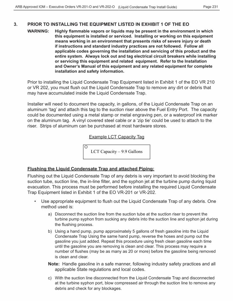
Installer will need to document the capacity, in gallons, of the Liquid Condensate Trap on an aluminum ‘tag’ and attach this tag to the suction riser above the Fuel Entry Port. The capacity could be documented using a metal stamp or metal engraving pen, or a waterproof ink marker on the aluminum tag. A vinyl covered steel cable or a ‘zip tie’ could be used to attach to the riser. Strips of aluminum can be purchased at most hardware stores.
Example LCT Capacity Tag
LCT Capacity – 9.9 Gallons
Flushing the Liquid Condensate Trap and attached Piping: Flushing out the Liquid Condensate Trap of any debris is very important to avoid blocking the suction tube, suction line, the in-line filter, and the syphon jet at the turbine pump during liquid evacuation. This process must be performed before installing the required Liquid Condensate Trap Equipment listed in Exhibit 1 of the EO VR-201 or VR-202.
• Use appropriate equipment to flush out the Liquid Condensate Trap of any debris. One method used is:
a) Disconnect the suction line from the suction tube at the suction riser to prevent the turbine pump syphon from sucking any debris into the suction line and syphon jet during the flushing process.
b) Using a hand pump, pump approximately 5 gallons of fresh gasoline into the Liquid Condensate Trap Using the same hand pump, reverse the hoses and pump out the gasoline you just added. Repeat this procedure using fresh clean gasoline each time until the gasoline you are removing is clean and clear. This process may require a number of flushes (may be as many as 20 or more) before the gasoline being removed is clean and clear.
Note: Handle gasoline in a safe manner, following industry safety practices and all applicable State regulations and local codes.
c) With the suction line disconnected from the Liquid Condensate Trap and disconnected at the turbine syphon port, blow compressed air through the suction line to remove any debris and check for any blockages.
ARB Approved IOM – Executive Orders VR-201-O and VR-202-O Page 232(Liquid Condensate Trap Install Guide)
4. INSTALLATION OF THE PHASE II EVR EQUIPMENT LISTED IN EXHIBIT 1 OF EO VR 201 AND 202
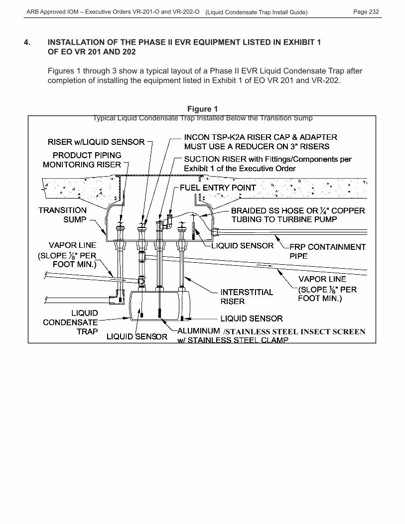
Figures 1 through 3 show a typical layout of a Phase II EVR Liquid Condensate Trap after completion of installing the equipment listed in Exhibit 1 of EO VR 201 and VR-202.
Figure 1Typical Liquid Condensate Trap Installed Below the Transition Sump
/STAINLESS STEEL INSECT SCREEN
ARB Approved IOM – Executive Orders VR-201-O and VR-202-O Page 233(Liquid Condensate Trap Install Guide)
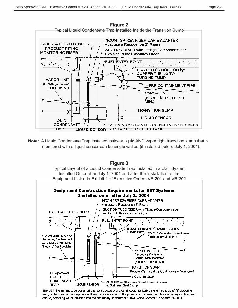
Figure 2Typical Liquid Condensate Trap Installed Inside the Transition Sump
/STAINLESS STEEL INSECT SCREEN
Note: A Liquid Condensate Trap installed inside a liquid AND vapor tight transition sump that is monitored with a liquid sensor can be single walled (if installed before July 1, 2004).
Figure 3Typical Layout of a Liquid Condensate Trap Installed in a UST System
Installed On or after July 1, 2004 and after the Installation of the Equipment Listed in Exhibit 1 of Executive Orders VR 201 and VR 202
or Stainless Steel Insect Screen
ARB Approved IOM – Executive Orders VR-201-O and VR-202-O Page 234(Liquid Condensate Trap Install Guide)
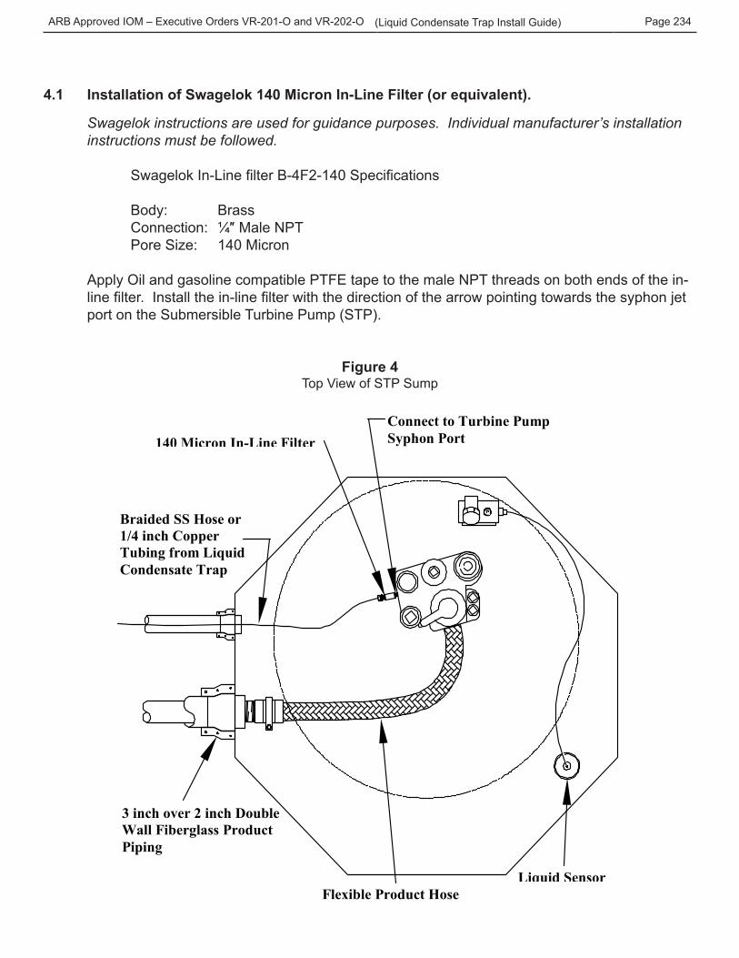
4.1 Installation of Swagelok 140 Micron In-Line Filter (or equivalent).
Swagelok instructions are used for guidance purposes. Individual manufacturer’s installation instructions must be followed.
Swagelok In-Line filter B-4F2-140 Specifications
Body: Brass Connection: ¼″ Male NPT Pore Size: 140 Micron
Apply Oil and gasoline compatible PTFE tape to the male NPT threads on both ends of the in-line filter. Install the in-line filter with the direction of the arrow pointing towards the syphon jet port on the Submersible Turbine Pump (STP).
Figure 4Top View of STP Sump
3 inch over 2 inch Double Wall Fiberglass Product Piping
Braided SS Hose or 1/4 inch Copper Tubing from Liquid Condensate Trap
140 Micron In-Line Filter
Flexible Product Hose
Connect to Turbine Pump Syphon Port
Liquid Sensor
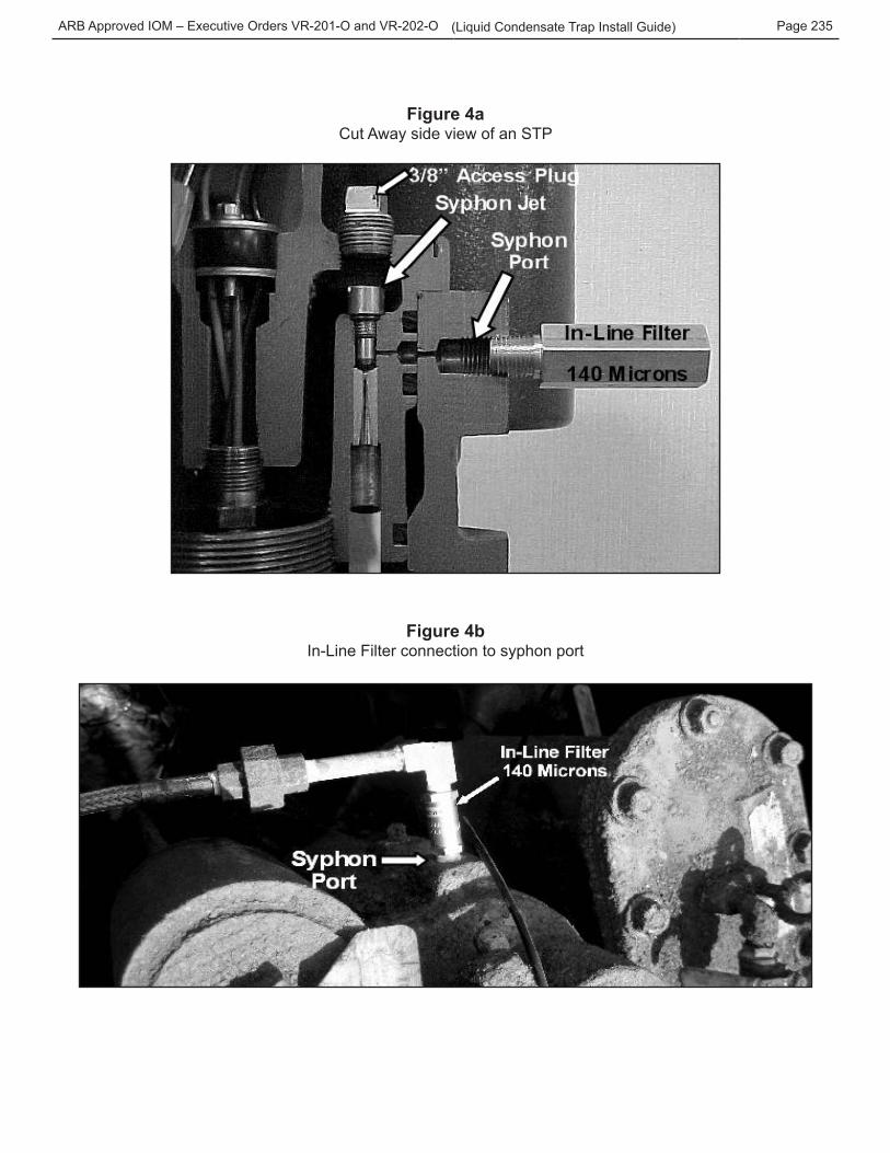
ARB Approved IOM – Executive Orders VR-201-O and VR-202-O Page 235(Liquid Condensate Trap Install Guide)
Figure 4aCut Away side view of an STP
Figure 4bIn-Line Filter connection to syphon port
ARB Approved IOM – Executive Orders VR-201-O and VR-202-O Page 236(Liquid Condensate Trap Install Guide)
4.1.1 Replacing Micron Filter Element Inside the In-Line Filter Swagelok (or equivalent) instructions are used for guidance purposes. Individual manufacturer’s installation instructions must be followed.
If the filter element becomes blocked from debris clean or replace the filter element – Swagelok P/N SS-4F-K4-140. See replacement instructions in Appendix B.
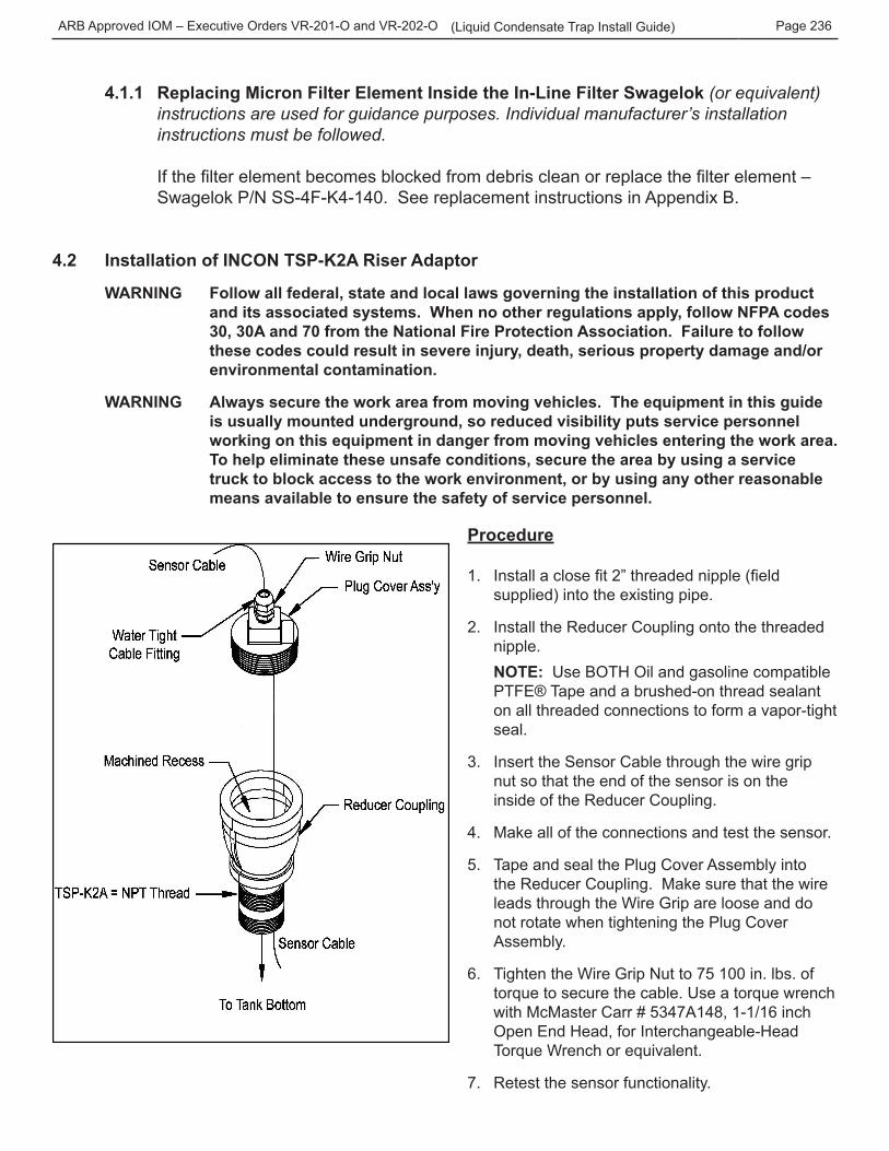
4.2 Installation of INCON TSP-K2A Riser Adaptor
WARNING Follow all federal, state and local laws governing the installation of this product and its associated systems. When no other regulations apply, follow NFPA codes 30, 30A and 70 from the National Fire Protection Association. Failure to follow these codes could result in severe injury, death, serious property damage and/or environmental contamination.
WARNING Always secure the work area from moving vehicles. The equipment in this guide is usually mounted underground, so reduced visibility puts service personnel working on this equipment in danger from moving vehicles entering the work area. To help eliminate these unsafe conditions, secure the area by using a service truck to block access to the work environment, or by using any other reasonable means available to ensure the safety of service personnel.
Procedure
1. Install a close fit 2” threaded nipple (field supplied) into the existing pipe.
2. Install the Reducer Coupling onto the threaded nipple.
NOTE: Use BOTH Oil and gasoline compatible PTFE® Tape and a brushed-on thread sealant on all threaded connections to form a vapor-tight seal.
3. Insert the Sensor Cable through the wire grip nut so that the end of the sensor is on the inside of the Reducer Coupling.
4. Make all of the connections and test the sensor.
5. Tape and seal the Plug Cover Assembly into the Reducer Coupling. Make sure that the wire leads through the Wire Grip are loose and do not rotate when tightening the Plug Cover Assembly.
6. Tighten the Wire Grip Nut to 75 100 in. lbs. of torque to secure the cable. Use a torque wrench with McMaster Carr # 5347A148, 1-1/16 inch Open End Head, for Interchangeable-Head Torque Wrench or equivalent.
7. Retest the sensor functionality.
ARB Approved IOM – Executive Orders VR-201-O and VR-202-O Page 237(Liquid Condensate Trap Install Guide)
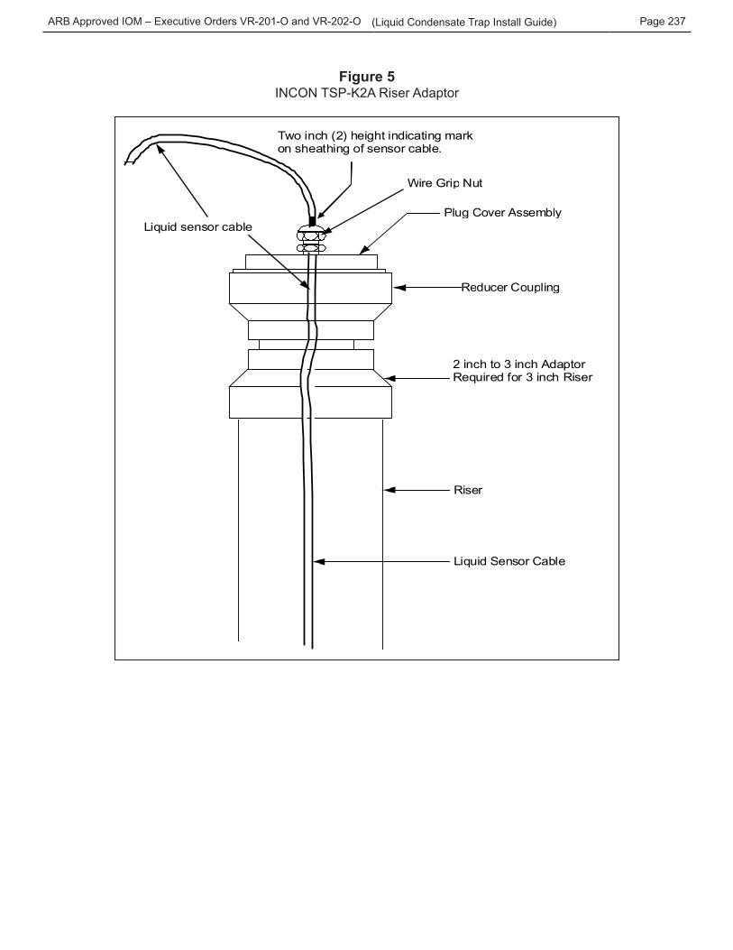
Figure 5INCON TSP-K2A Riser Adaptor
W i r e G r i p N u t
P l u g C o v e r A s s e m b l y
R e d u c e r C o u p l i n g
R i s e r
L i q u i d S e n s o r C a b l e
2 inch to 3 inch Adaptor Required for 3 inch Riser
Liquid sensor cable
Two inch (2) height indicating mark on sheathing of sensor cable.
ARB Approved IOM – Executive Orders VR-201-O and VR-202-O Page 238(Liquid Condensate Trap Install Guide)
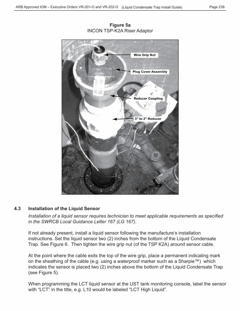
Figure 5aINCON TSP-K2A Riser Adaptor
4.3 Installation of the Liquid Sensor Installation of a liquid sensor requires technician to meet applicable requirements as specified in the SWRCB Local Guidance Letter 167 (LG 167).
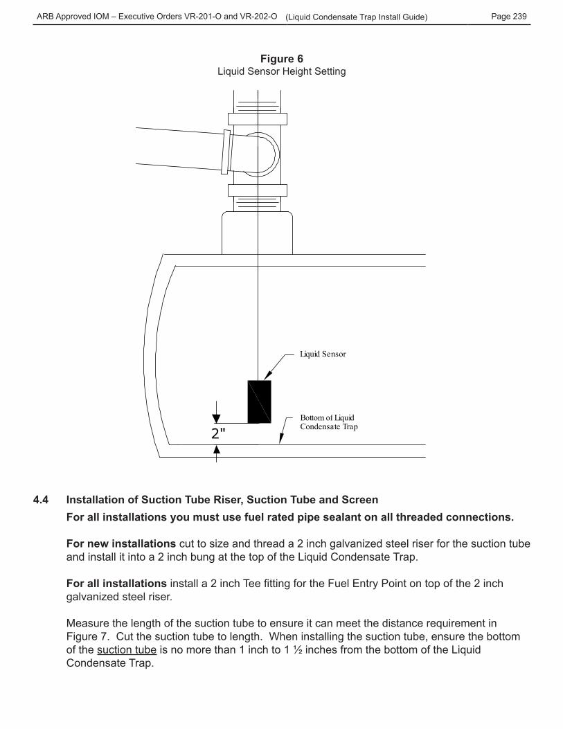
If not already present, install a liquid sensor following the manufacture’s installation instructions. Set the liquid sensor two (2) inches from the bottom of the Liquid Condensate Trap. See Figure 6. Then tighten the wire grip nut (of the TSP K2A) around sensor cable.
At the point where the cable exits the top of the wire grip, place a permanent indicating mark on the sheathing of the cable (e.g. using a waterproof marker such as a Sharpie™) which indicates the sensor is placed two (2) inches above the bottom of the Liquid Condensate Trap (see Figure 5).
When programming the LCT liquid sensor at the UST tank monitoring console, label the sensor with “LCT” in the title, e.g. L10 would be labeled “LCT High Liquid”.
ARB Approved IOM – Executive Orders VR-201-O and VR-202-O Page 239(Liquid Condensate Trap Install Guide)
Figure 6Liquid Sensor Height Setting
L i q u i d S e n s o r
B o t t o m o f L i q u i d C o n d e n s a t e T r a p
4.4 Installation of Suction Tube Riser, Suction Tube and ScreenFor all installations you must use fuel rated pipe sealant on all threaded connections.
For new installations cut to size and thread a 2 inch galvanized steel riser for the suction tube and install it into a 2 inch bung at the top of the Liquid Condensate Trap. For all installations install a 2 inch Tee fitting for the Fuel Entry Point on top of the 2 inch galvanized steel riser.
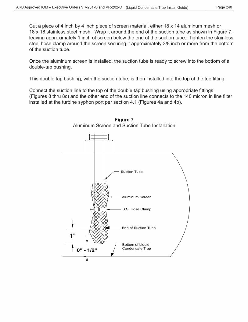
Measure the length of the suction tube to ensure it can meet the distance requirement in Figure 7. Cut the suction tube to length. When installing the suction tube, ensure the bottom of the suction tube is no more than 1 inch to 1 ½ inches from the bottom of the Liquid Condensate Trap.
ARB Approved IOM – Executive Orders VR-201-O and VR-202-O Page 240(Liquid Condensate Trap Install Guide)
Cut a piece of 4 inch by 4 inch piece of screen material, either 18 x 14 aluminum mesh or 18 x 18 stainless steel mesh. Wrap it around the end of the suction tube as shown in Figure 7, leaving approximately 1 inch of screen below the end of the suction tube. Tighten the stainless steel hose clamp around the screen securing it approximately 3/8 inch or more from the bottom of the suction tube.
Once the aluminum screen is installed, the suction tube is ready to screw into the bottom of a double-tap bushing.
This double tap bushing, with the suction tube, is then installed into the top of the tee fitting.
Connect the suction line to the top of the double tap bushing using appropriate fittings (Figures 8 thru 8c) and the other end of the suction line connects to the 140 micron in line filter installed at the turbine syphon port per section 4.1 (Figures 4a and 4b).
Figure 7Aluminum Screen and Suction Tube Installation
Suction Tube
Aluminum Screen
S.S. Hose Clamp
End of Suction Tube
Bottom of LiquidCondensate Trap
ARB Approved IOM – Executive Orders VR-201-O and VR-202-O Page 241(Liquid Condensate Trap Install Guide)
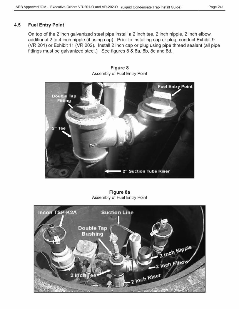
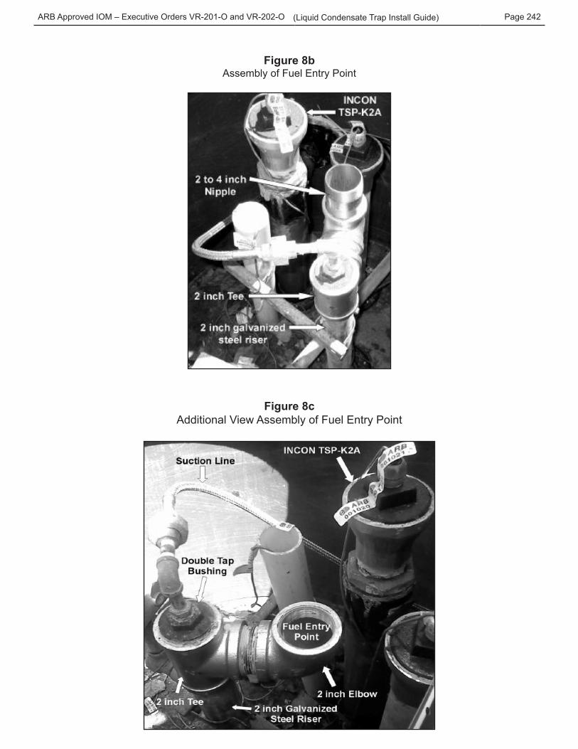
4.5 Fuel Entry Point
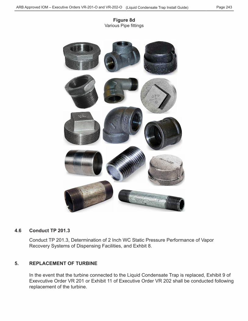
On top of the 2 inch galvanized steel pipe install a 2 inch tee, 2 inch nipple, 2 inch elbow, additional 2 to 4 inch nipple (if using cap). Prior to installing cap or plug, conduct Exhibit 9 (VR 201) or Exhibit 11 (VR 202). Install 2 inch cap or plug using pipe thread sealant (all pipe fittings must be galvanized steel.) See figures 8 & 8a, 8b, 8c and 8d.
Figure 8Assembly of Fuel Entry Point
Figure 8aAssembly of Fuel Entry Point
ARB Approved IOM – Executive Orders VR-201-O and VR-202-O Page 242(Liquid Condensate Trap Install Guide)
Figure 8bAssembly of Fuel Entry Point
Figure 8cAdditional View Assembly of Fuel Entry Point
ARB Approved IOM – Executive Orders VR-201-O and VR-202-O Page 243(Liquid Condensate Trap Install Guide)
Figure 8dVarious Pipe fittings
4.6 Conduct TP 201.3
Conduct TP 201.3, Determination of 2 Inch WC Static Pressure Performance of Vapor Recovery Systems of Dispensing Facilities, and Exhbit 8.
5. REPLACEMENT OF TURBINE
In the event that the turbine connected to the Liquid Condensate Trap is replaced, Exhibit 9 of Exevcutive Order VR 201 or Exhibit 11 of Executive Order VR 202 shall be conducted following replacement of the turbine.
ARB Approved IOM – Executive Orders VR-201-O and VR-202-O Page 244(Liquid Condensate Trap Install Guide)
TROUBLESHOOTING PROCEDURES FOR LIQUID CONDENSATE TRAP
WARNING: Installing or working on this equipment means working in an environment that presents risks of severe injury or death if instructions and standard industry practices are not followed. Obey all applicable codes governing the installation and servicing of this product and the entire system. Always lock out and tag electrical circuit breakers while installing or servicing this equipment and related equipment.
1. Test The Turbine Pump For Normal Vacuum Readings:
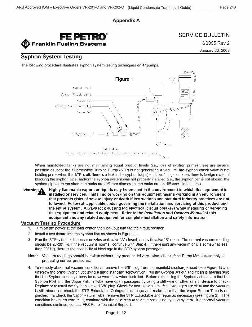
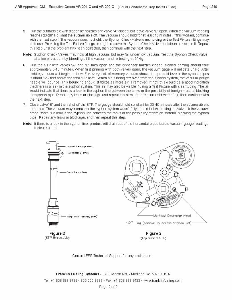
• Follow FE Petro syphon jet test procedures. See Appendix A, FFS FE Petro Service
Bulletin SB005 “Syphon System Testing” (SB005). When using this test procedure for testing the turbine pump connected to the Liquid Condensate Trap only, perform Steps 1– 4. Do not use a syphon check valve and skip the syphon check valve test (for other turbine pump manufacturers, refer to their test procedure.)
• This will ensure the turbine pump is operating correctly and producing the correct amount of vacuum at the syphon port (minimum vacuum is 16 to 28 inches Hg). Make any necessary repairs to the turbine pump to meet the syphon port minimum vacuum levels.
• If the turbine pump is creating the appropriate amount of vacuum (16 to 28 inches Hg) at the syphon port, remove the test fixture called out in SB005 and install the 140 micron in line filter.
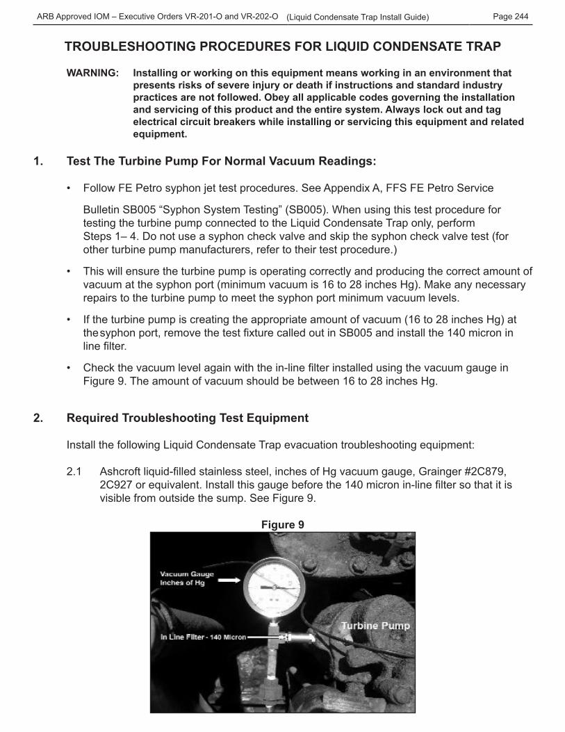
• Check the vacuum level again with the in-line filter installed using the vacuum gauge in Figure 9. The amount of vacuum should be between 16 to 28 inches Hg.
2. Required Troubleshooting Test Equipment
Install the following Liquid Condensate Trap evacuation troubleshooting equipment:
2.1 Ashcroft liquid-filled stainless steel, inches of Hg vacuum gauge, Grainger #2C879, 2C927 or equivalent. Install this gauge before the 140 micron in-line filter so that it is visible from outside the sump. See Figure 9.
Figure 9
ARB Approved IOM – Executive Orders VR-201-O and VR-202-O Page 245(Liquid Condensate Trap Install Guide)
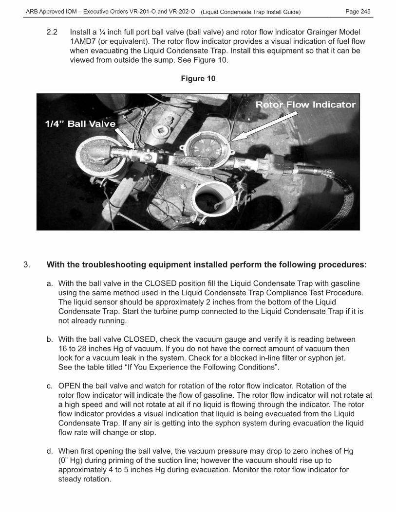
2.2 Install a ¼ inch full port ball valve (ball valve) and rotor flow indicator Grainger Model 1AMD7 (or equivalent). The rotor flow indicator provides a visual indication of fuel flow when evacuating the Liquid Condensate Trap. Install this equipment so that it can be viewed from outside the sump. See Figure 10.
Figure 10
3. With the troubleshooting equipment installed perform the following procedures:
a. With the ball valve in the CLOSED position fill the Liquid Condensate Trap with gasoline using the same method used in the Liquid Condensate Trap Compliance Test Procedure. The liquid sensor should be approximately 2 inches from the bottom of the Liquid Condensate Trap. Start the turbine pump connected to the Liquid Condensate Trap if it is not already running.
b. With the ball valve CLOSED, check the vacuum gauge and verify it is reading between 16 to 28 inches Hg of vacuum. If you do not have the correct amount of vacuum then look for a vacuum leak in the system. Check for a blocked in-line filter or syphon jet.
See the table titled “If You Experience the Following Conditions”.
c. OPEN the ball valve and watch for rotation of the rotor flow indicator. Rotation of the rotor flow indicator will indicate the flow of gasoline. The rotor flow indicator will not rotate at a high speed and will not rotate at all if no liquid is flowing through the indicator. The rotor flow indicator provides a visual indication that liquid is being evacuated from the Liquid Condensate Trap. If any air is getting into the syphon system during evacuation the liquid flow rate will change or stop.
d. When first opening the ball valve, the vacuum pressure may drop to zero inches of Hg (0” Hg) during priming of the suction line; however the vacuum should rise up to approximately 4 to 5 inches Hg during evacuation. Monitor the rotor flow indicator for steady rotation.
ARB Approved IOM – Executive Orders VR-201-O and VR-202-O Page 246(Liquid Condensate Trap Install Guide)
e. When the Liquid Condensate Trap is almost empty and/or the liquid is below the end of the suction tube the rotor flow indicator will stop then start a few times and then completely stop. This is an indication that air is getting into the system. If the liquid sensor is out of alarm and the Liquid Condensate Trap is empty or almost empty (liquid level is at or below the bottom of the suction tube) you have successfully evacuated the Liquid Condensate Trap. Note: At this time the vacuum gauge will read near zero inches of Hg (0” Hg) because the suction tube is sucking in air and not liquid.
4. Passed this Troubleshooting Section
When you have successfully passed this Troubleshooting section, remove the troubleshooting equipment and retest the system again using the “Liquid Condensate Trap Compliance Test Procedure” (VR 201 Exhibit 9, VR 202 Exhibit 11).
ARB Approved IOM – Executive Orders VR-201-O and VR-202-O Page 247(Liquid Condensate Trap Install Guide)
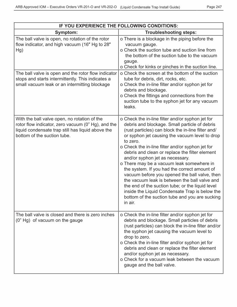
IF YOU EXPERIENCE THE FOLLOWING CONDITIONS:Symptom: Troubleshooting steps:
The ball valve is open, no rotation of the rotor flow indicator, and high vacuum (16″ Hg to 28″ Hg)
o There is a blockage in the piping before the vacuum gauge. o Check the suction tube and suction line from the bottom of the suction tube to the vacuum gauge. o Check for kinks or pinches in the suction line.
The ball valve is open and the rotor flow indicator stops and starts intermittently. This indicates a small vacuum leak or an intermitting blockage
o Check the screen at the bottom of the suction tube for debris, dirt, rocks, etc.o Check the in-line filter and/or syphon jet for debris and blockage.o Check the fittings and connections from the suction tube to the syphon jet for any vacuum leaks.
With the ball valve open, no rotation of the rotor flow indicator, zero vacuum (0” Hg), and the liquid condensate trap still has liquid above the bottom of the suction tube.
o Check the in-line filter and/or syphon jet for debris and blockage. Small particle of debris (rust particles) can block the in-line filter and/ or syphon jet causing the vacuum level to drop to zero. o Check the in-line filter and/or syphon jet for debris and clean or replace the filter element and/or syphon jet as necessary.o There may be a vacuum leak somewhere in the system. If you had the correct amount of vacuum before you opened the ball valve, then the vacuum leak is between the ball valve and the end of the suction tube; or the liquid level inside the Liquid Condensate Trap is below the bottom of the suction tube and you are sucking in air.
The ball valve is closed and there is zero inches (0” Hg) of vacuum on the gauge
o Check the in-line filter and/or syphon jet for debris and blockage. Small particles of debris (rust particles) can block the in-line filter and/or the syphon jet causing the vacuum level to drop to zero. o Check the in-line filter and/or syphon jet for debris and clean or replace the filter element and/or syphon jet as necessary.o Check for a vacuum leak between the vacuum gauge and the ball valve.
ARB Approved IOM – Executive Orders VR-201-O and VR-202-O Page 248(Liquid Condensate Trap Install Guide)
Appendix A
ARB Approved IOM – Executive Orders VR-201-O and VR-202-O Page 249(Liquid Condensate Trap Install Guide)
ARB Approved IOM – Executive Orders VR-201-O and VR-202-O Page 250(Liquid Condensate Trap Install Guide)
Appendix B
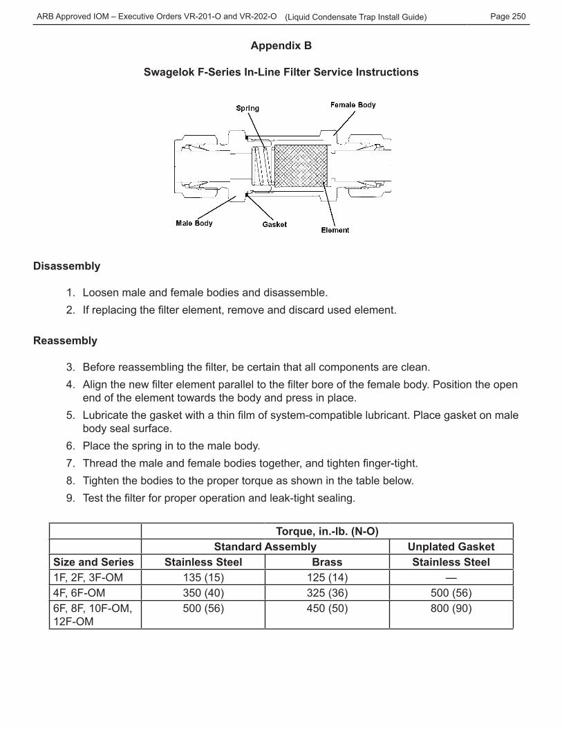
Swagelok F-Series In-Line Filter Service Instructions
Disassembly
1. Loosen male and female bodies and disassemble.2. If replacing the filter element, remove and discard used element.
Reassembly
3. Before reassembling the filter, be certain that all components are clean.4. Align the new filter element parallel to the filter bore of the female body. Position the open
end of the element towards the body and press in place.5. Lubricate the gasket with a thin film of system-compatible lubricant. Place gasket on male
body seal surface.6. Place the spring in to the male body.7. Thread the male and female bodies together, and tighten finger-tight.8. Tighten the bodies to the proper torque as shown in the table below.9. Test the filter for proper operation and leak-tight sealing.
Torque, in.-lb. (N-O)Standard Assembly Unplated Gasket
Size and Series Stainless Steel Brass Stainless Steel1F, 2F, 3F-OM 135 (15) 125 (14) —4F, 6F-OM 350 (40) 325 (36) 500 (56)6F, 8F, 10F-OM, 12F-OM
500 (56) 450 (50) 800 (90)
ARB Approved IOM – Executive Orders VR-201-O and VR-202-O Page 251(Liquid Condensate Trap Install Guide)