Embed Size (px)
Citation preview
150 International Journal for Modern Trends in Science and Technology
Drift Avoidance Mechanism in Maximum Power
Point Tracking Using Artificial Neural Network
Pushpendra Kumar1 | Ritesh Diwan2
1PG Scholar, Power Electronics, Raipur Institute of Technology, Raipur
2Associate Professor, Power Electronics, Raipur Institute of Technology, Raipur
To Cite this Article Pushpendra Kumar and Ritesh Diwan, “Drift Avoidance Mechanism in Maximum Power Point Tracking Using Artificial Neural Network”, International Journal for Modern Trends in Science and Technology, Vol. 03, Issue 06, June 2017, pp. 150-155.
As the requirement of Photovoltaic System escalates since it uses the solar energy which is one of the
renewable energies for the electrical energy it’s production has an enormous potential. The development of
PV system is very rapid as compared to its counterparts of the renewable energies like wind energy. The DC
voltage which is generated by the Photovoltaic system will be boosted by the DC-DC Boost converter. The
utility grid is incorporated with the PV Solar Power Generator through the 3-ı PWM DC-AC inverter, whose
control is provided by a constant current controller which employs MOSFET Switch. This controller will use a
3-ı phase locked loop (PLL) for tracking the phase angle of the utility grid and reacts very fast enough to the
changes in load or grid connection states , as a result, it seems to be very efficient in supplying to load the
constant voltage without phase jump. An artificial neural network which consist of device with having many
inputs and one output. By using artificial neuron networks, the control algorithm implemented in the SEPIC
converter enhances by reducing the response time and hence, transient response for this drift settling time is
improved.
Keyword: - Photovoltaic system, DC-DC Converter, SEPIC converter, artificial neural networks.
Copyright © 2017 International Journal for Modern Trends in Science and Technology
All rights reserved.
I. INTRODUCTION
Renewable energy is usually outlined as energy
that comes from resources that area unit naturally
replenished on a person's duration like daylight,
wind, rain, tides, waves and geothermic heat.
Renewable energy replaces conventional fuels in
four distinct areas: electricity generation, hot
water/space heating, motor fuels, and rural
(off-grid) energy services. electrical phenomenon
(PV) technology converts one kind of energy
(sunlight) into another kind of energy (electricity)
exploitation no moving elements, overwhelming no
typical fossil fuels, making no pollution, and
lasting for decades with little or no maintenance
PV panels tend to figure far better in weather than
in hot climates (except for amorphous atomic
number 14 panels). Add a reflective snow surface
and therefore the output will typically exceed the
rating for the panel. Array currents up to 20%
larger than the required output are reportable. In
general, PV materials ar classified as either
crystalline or skinny film, and that they ar judged
on 2 basic factors: potency and economic science.
For remote installations where the particular
house accessible for PV panels is usually quite
restricted, the larger conversion potency of
crystalline technology appears to own the
advantage. It’s additionally value noting that the
conversion potency of thin-film panels tends to
drop off rather chop-chop within the 1st few years
of operation. Decreases of quite twenty fifth have
ABSTRACT
International Journal for Modern Trends in Science and Technology
Volume: 03, Issue No: 06, June 2017
ISSN: 2455-3778
http://www.ijmtst.com
151 International Journal for Modern Trends in Science and Technology
Pushpendra Kumar and Ritesh Diwan: Drift Avoidance Mechanism in Maximum Power Point Tracking Using Artificial Neural Network
been reported. This performance deterioration
should be taken into consideration once size the
array for a multi-year project Operating mutely and
with none moving components or environmental
emissions, PV systems have developed from being
niche market applications into a mature
technology used for thought electricity generation.
A roof-top system recoups the endowed energy for
its producing and installation among zero.7 to two
years and produces concerning ninety five Percent
of internet clean renewable over a 30-year service
life.Conventional c-Si star cells, usually wired
serial, square measure encapsulated in an
exceedingly star module to safeguard them from
the weather. The module consists of a tempered
glass as cowl, a soft and versatile encapsulate, a
rear back sheet made of a weathering Associate in
Nursing d non combustible material and an
metallic element frame round the outer reaches.
Electrically connected and mounted on a
structure, star modules build a string of modules,
typically referred to as solar battery. A electrical
device consists of 1 or several such panels. An
electrical phenomenon array, or electrical device,
could be a joined assortment of star panels. The
Power that one module will manufacture is rarely
enough to satisfy necessities of a home or a
business, that the modules square measure linked
along to make Associate in Nursing array
1.1 SEPIC CONVERTER
The single-ended primary-inductor convertor
(SEPIC) is a type of DC/DC convertor permitting
the voltage at its output to be bigger than, less
than, or adequate that at its input. The SEPIC
convertor combines the most effective qualities of
each the boost convertor and fly back convertor. A
SEPIC is actually a lift convertor followed by a
buck-boost convertor, thus it's almost like a
traditional buck-boost convertor, however has
benefits of having non-inverted output (the output
has a similar voltage polarity because the input).
This convertor can scale back current ripples at the
input for low level DC outputs, thus eliminating the
requirement for a high frequency filter at
the AC aspect, and therefore the voltage stresses on
the switches reduced. Whereas this convertor is
incredibly smart for prime voltage applications
once operated in CCM, it's higher for low voltage
choices only if operated in DCM mode.
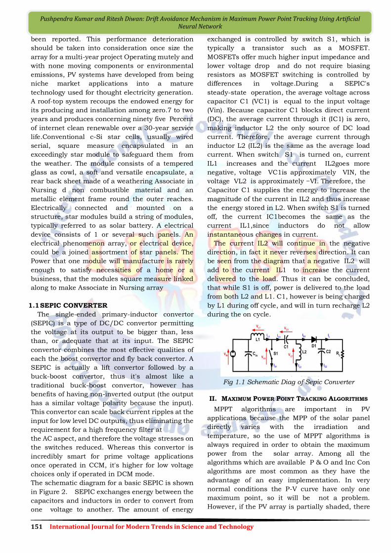
The schematic diagram for a basic SEPIC is shown
in Figure 2. SEPIC exchanges energy between the
capacitors and inductors in order to convert from
one voltage to another. The amount of energy
exchanged is controlled by switch S1, which is
typically a transistor such as a MOSFET.
MOSFETs offer much higher input impedance and
lower voltage drop and do not require biasing
resistors as MOSFET switching is controlled by
differences in voltage.During a SEPIC's
steady-state operation, the average voltage across
capacitor C1 (VC1) is equal to the input voltage
(Vin). Because capacitor C1 blocks direct current
(DC), the average current through it (IC1) is zero,
making inductor L2 the only source of DC load
current. Therefore, the average current through
inductor L2 (IL2) is the same as the average load
current. When switch S1 is turned on, current
IL1 increases and the current IL2goes more
negative, voltage VC1is approximately VIN, the
voltage VL2 is approximately −VI. Therefore, the
Capacitor C1 supplies the energy to increase the
magnitude of the current in IL2 and thus increase
the energy stored in L2. When switch S1 is turned
off, the current IC1becomes the same as the
current IL1,since inductors do not allow
instantaneous changes in current.
The current IL2 will continue in the negative
direction, in fact it never reverses direction. It can
be seen from the diagram that a negative IL2 will
add to the current IL1 to increase the current
delivered to the load. Thus it can be concluded,
that while S1 is off, power is delivered to the load
from both L2 and L1. C1, however is being charged
by L1 during off cycle, and will in turn recharge L2
during the on cycle.
Fig 1.1 Schematic Diag of Sepic Converter
II. MAXIMUM POWER POINT TRACKING ALGORITHMS
MPPT algorithms are important in PV
applications because the MPP of the solar panel
directly varies with the irradiation and
temperature, so the use of MPPT algorithms is
always required in order to obtain the maximum
power from the solar array. Among all the
algorithms which are available P & O and Inc Con
algorithms are most common as they have the
advantage of an easy implementation. In very
normal conditions the P-V curve have only one
maximum point, so it will be not a problem.
However, if the PV array is partially shaded, there
152 International Journal for Modern Trends in Science and Technology
Pushpendra Kumar and Ritesh Diwan: Drift Avoidance Mechanism in Maximum Power Point Tracking Using Artificial Neural Network
will be multiple maxima in these curves.
2.1 Curve Fitting method
The curve-fitting method is the method where PV
module characteristics and all data and
manufacturing details which are required, for
mathematical modelling and equations describing
the output characteristics are pre-decided. PV
module characteristic is given by eq. (1), where a, b,
c and d are coefficients which are determined by
sampling m values of PV voltage VPV, PV current IPV
and output power PPV [Salas, 2006]. Once these
coefficients are calculated, the voltage at which
power become maximum is obtained by eq. (2).
PPV = a VPV3 + b VPV
2 + c VPV + d (1)
The advantage of this method is its very
simplicity. Disadvantage is that it requires prior
and accurate knowledge of physical parameters. It
requires large memory as number of calculation is
more and the Speed is less.
2.2 Differential Method
In this method, eq. (3) must be solved very fast in
order to provide the accurate operating point.
Disadvantage of this method is that it requires
extensive calculation time as after calculating eq.
(3) parameters, sum + is calculated and a
comparison of these sum to an equal perturbation
on the opposite side of the operating point or the
operating point power. This will be done till final
sum becomes zero and if not than more
calculations are required [Salas, 2006].
2.3 Open-Circuit Voltage method
In this method the ratio of PV array’s maximum
power voltage (VMPP) to its open-circuit voltage
(VOC) is approximately constant as given by eq. (4).
The Open-Circuit method will be implemented
using the flowchart as shown in fig. 1. The PV array
is transitory isolated using from MPPT then VOC is
measured. After that VMPP is calculated
according to eq. (4), finally the operation voltage is
set for the maximum voltage point. This process is
repeated periodically
The core Advantage of this method is that it is
simple and very cheap. Disadvantage is that it is
quite difficult to choose an optimal value of
constant K1.
The literature [Salas, 2006 & Eltawil, 2013],
reports K1 values ranging from 0.73 to 0.80 for
Polycrystalline PV modules.
2.4 Short-Circuit Method
This method is very similar to Open-Circuit
Voltage method, in this the current in MPP (IMPP)
and it is linearly proportional to Short-Circuit
current (ISC) given by eq. (5). The value of K2 is
considered to be around 0.85 [Salas, 2006].
The way of evaluating K2 is quite more
complicated than any of fixed value. The flowchart,
advantages and disadvantages are similar to that
of Open-Circuit Voltage method.
2.5 Hill Climbing Techniques
P & O and Inc Con algorithms operate on Hill
Climbing Principle, in which operating point of the
PV module moves in the increasing direction of
power [Morales, 2010].
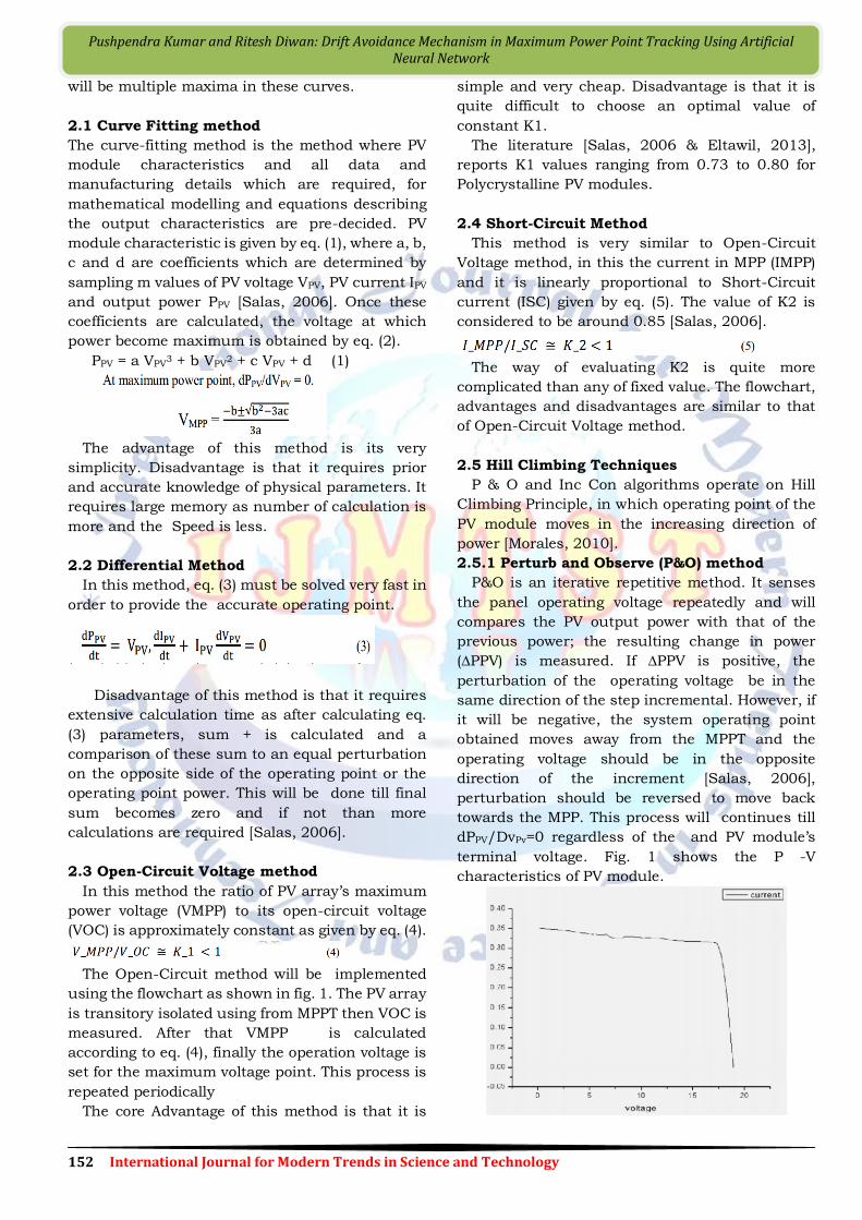
2.5.1 Perturb and Observe (P&O) method
P&O is an iterative repetitive method. It senses
the panel operating voltage repeatedly and will
compares the PV output power with that of the
previous power; the resulting change in power
(∆PPV) is measured. If ∆PPV is positive, the
perturbation of the operating voltage be in the
same direction of the step incremental. However, if
it will be negative, the system operating point
obtained moves away from the MPPT and the
operating voltage should be in the opposite
direction of the increment [Salas, 2006],
perturbation should be reversed to move back
towards the MPP. This process will continues till
dPPV/DvPv=0 regardless of the and PV module’s
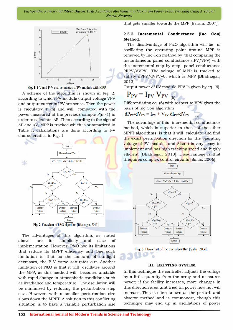
terminal voltage. Fig. 1 shows the P -V
characteristics of PV module.
153 International Journal for Modern Trends in Science and Technology
Pushpendra Kumar and Ritesh Diwan: Drift Avoidance Mechanism in Maximum Power Point Tracking Using Artificial Neural Network
A scheme of the algorithm is shown in Fig. 2,
according to which PV module output voltage VPV
and output currents IPV are sense. Then the power
is calculated P (n) and will compared with the
power measured at the previous sample P(n -1) in
order to calculate ∆P. Then according to the sign of
∆P and ∆V, MPP is tracked which is summarized in
Table I, calculations are done according to I-V
characteristics in Fig. 1
The advantages of this algorithm, as stated
above, are its simplicity and ease of
implementation. However, P&O hve its limitations
that reduce its MPPT efficiency and One such
limitation is that as the amount of sunlight
decreases, the P–V curve saturates out. Another
limitation of P&O is that it will oscillates around
the MPP, as this method will becomes unstable
with rapid change in atmospheric conditions such
as irradiance and temperature. The oscillation will
be minimized by reducing the perturbation step
size. However, with a smaller perturbation size
slows down the MPPT. A solution to this conflicting
situation is to have a variable perturbation size
that gets smaller towards the MPP [Esram, 2007].
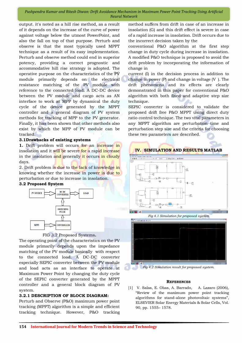
2.5.2 Incremental Conductance (Inc Con)
Method.
The disadvantage of P&O algorithm will be of
oscillating the operating point around MPP is
removed by Inc Con method by that comparing the
instantaneous panel conductance (IPV/VPV) with
the incremental step by step panel conductance
(dIPV/dVPV). The voltage of MPP is tracked to
satisfy dPPV/dVPV=0, which is MPP [Bhatnagar,
2013]
Output power of PV module PPV Is given by eq. (6).
(6)
Differentiating eq. (6) with respect to VPV gives the
basis of Inc Con algorithm
(7)
The advantage of this incremental conductance
method, which is superior to those of the other
MPPT algorithms, is that it will calculate and find
the exact perturbation direction for the operating
voltage of PV modules and Also it is very easy to
implement and has high tracking speed and highly
efficient [Bhatnagar, 2013]. Disadvantage is that
itrequires complex control circuits [Salas, 2006].
III. EXISTING SYSTEM
In this technique the controller adjusts the voltage
by a little quantity from the array and measures
power; if the facility increases, more changes in
this direction area unit tried till power now not will
increase. This is often known as the perturb and
observe method and is commonest, though this
technique may end up in oscillations of power
154 International Journal for Modern Trends in Science and Technology
Pushpendra Kumar and Ritesh Diwan: Drift Avoidance Mechanism in Maximum Power Point Tracking Using Artificial Neural Network
output. it's noted as a hill rise method, as a result
of it depends on the increase of the curve of power
against voltage below the utmost PowerPoint, and
also the fall on top of that purpose. Perturb and
observe is that the most typically used MPPT
technique as a result of its easy implementation.
Perturb and observe method could end in superior
potency, providing a correct prognostic and
accommodative hill rise strategy is adopted. The
operative purpose on the characteristics of the PV
module primarily depends on the electrical
resistance matching of the PV module with
reference to the connected load. A DC-DC device
between the PV module and cargo acts as AN
interface to work at MPP by dynamical the duty
cycle of the device generated by the MPPT
controller and a general diagram of PV system
methods for tracking of MPP to the PV generator.
Finally, it has been shown that other methods also
exist by which the MPP of PV module can be
tracked.
3.1Drawbacks of existing systems
1. Drift problem will occurs for an increase in
insolation and it will be severe for a rapid increase
in the insolation and generally it occurs in cloudy
days.
2. Drift problem is due to the lack of knowledge in
knowing whether the increase in power is due to
perturbation or due to increase in insolation.
3.2 Proposed System
FIG 3.2 Proposed Systems.
The operating point of the characteristics on the PV
module primarily depends upon the impedance
matching of the PV module basically with respect
to the connected load. A DC-DC converter
especially SEPIC converter between the PV module
and load acts as an interface to operate at
Maximum Power Point by changing the duty cycle
of the SEPIC converter generated by the MPPT
controller and a general block diagram of PV
system.
3.2.1 DESCRIPTION OF BLOCK DIAGRAM:
Perturb and Observe (P&O) maximum power point
tracking (MPPT) algorithm is a simple and efficient
tracking technique. However, P&O tracking
method suffers from drift in case of an increase in
insolation (G) and this drift effect is severe in case
of a rapid increase in insolation. Drift occurs due to
the incorrect decision taken by the
conventional P&O algorithm at the first step
change in duty cycle during increase in insolation.
A modified P&O technique is proposed to avoid the
drift problem by incorporating the information of
change in
current (I) in the decision process in addition to
change in power (P) and change in voltage (V ). The
drift phenomena and its effects are clearly
demonstrated in this paper for conventional P&O
algorithm with both fixed and adaptive step size
technique.
SEPIC converter is considered to validate the
proposed drift free P&O MPPT using direct duty
ratio control technique. The two vital parameters in
any MPPT algorithm are perturbation time and
perturbation step size and the criteria for choosing
these two parameters are described.
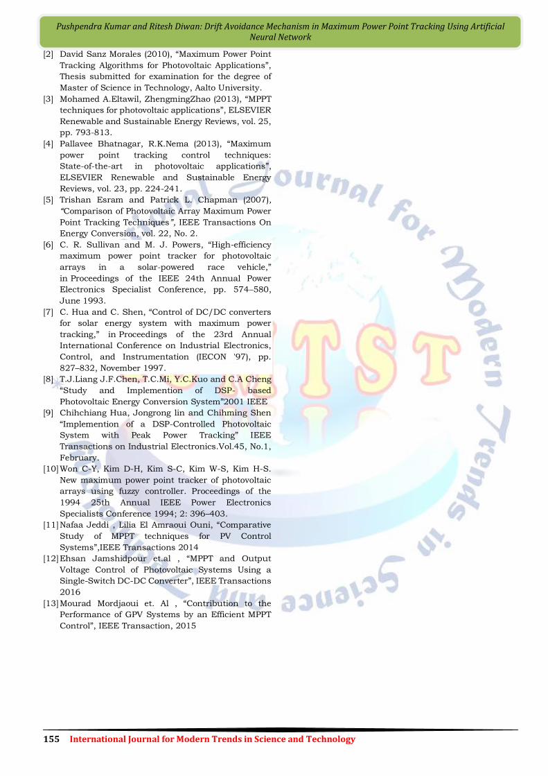
IV. SIMULATION AND RESULTS MATLAB
Fig 4.1 Simulation for proposed system
Fig 4.2 Simulation result for proposed system.
REFERENCES
[1] V. Salas, E. Olıas, A. Barrado, A. Lazaro (2006),
“Review of the maximum power point tracking
algorithms for stand-alone photovoltaic systems”,
ELSEVIER Solar Energy Materials & Solar Cells, Vol.
90, pp. 1555– 1578.
155 International Journal for Modern Trends in Science and Technology
Pushpendra Kumar and Ritesh Diwan: Drift Avoidance Mechanism in Maximum Power Point Tracking Using Artificial Neural Network
[2] David Sanz Morales (2010), “Maximum Power Point
Tracking Algorithms for Photovoltaic Applications”,
Thesis submitted for examination for the degree of
Master of Science in Technology, Aalto University.
[3] Mohamed A.Eltawil, ZhengmingZhao (2013), “MPPT
techniques for photovoltaic applications”, ELSEVIER
Renewable and Sustainable Energy Reviews, vol. 25,
pp. 793-813.
[4] Pallavee Bhatnagar, R.K.Nema (2013), “Maximum
power point tracking control techniques:
State-of-the-art in photovoltaic applications”,
ELSEVIER Renewable and Sustainable Energy
Reviews, vol. 23, pp. 224-241.
[5] Trishan Esram and Patrick L. Chapman (2007),
“Comparison of Photovoltaic Array Maximum Power
Point Tracking Techniques”, IEEE Transactions On
Energy Conversion, vol. 22, No. 2.
[6] C. R. Sullivan and M. J. Powers, “High-efficiency
maximum power point tracker for photovoltaic
arrays in a solar-powered race vehicle,”
in Proceedings of the IEEE 24th Annual Power
Electronics Specialist Conference, pp. 574–580,
June 1993.
[7] C. Hua and C. Shen, “Control of DC/DC converters
for solar energy system with maximum power
tracking,” in Proceedings of the 23rd Annual
International Conference on Industrial Electronics,
Control, and Instrumentation (IECON '97), pp.
827–832, November 1997.
[8] T.J.Liang J.F.Chen, T.C.Mi, Y.C.Kuo and C.A Cheng
“Study and Implemention of DSP- based
Photovoltaic Energy Conversion System”2001 IEEE
[9] Chihchiang Hua, Jongrong lin and Chihming Shen
“Implemention of a DSP-Controlled Photovoltaic
System with Peak Power Tracking” IEEE
Transactions on Industrial Electronics.Vol.45, No.1,
February.
[10] Won C-Y, Kim D-H, Kim S-C, Kim W-S, Kim H-S.
New maximum power point tracker of photovoltaic
arrays using fuzzy controller. Proceedings of the
1994 25th Annual IEEE Power Electronics
Specialists Conference 1994; 2: 396–403.
[11] Nafaa Jeddi , Lilia El Amraoui Ouni, “Comparative
Study of MPPT techniques for PV Control
Systems”,IEEE Transactions 2014
[12] Ehsan Jamshidpour et.al , “MPPT and Output
Voltage Control of Photovoltaic Systems Using a
Single-Switch DC-DC Converter”, IEEE Transactions
2016
[13] Mourad Mordjaoui et. Al , “Contribution to the
Performance of GPV Systems by an Efficient MPPT
Control”, IEEE Transaction, 2015