Embed Size (px)
Citation preview
Copyright 2002 AADE Technical Conference
This paper was prepared for presentation at the AADE 2002 Technology Conference “Drilling & Completion Fluids and Waste Management”, held at the Radisson Astrodome,Houston, Texas, April 2 - 3,2002 in Houston, Texas. This conference was hosted by the Houston Chapter of the American Association of Drilling Engineers. The information presented in this paper does not reflect any position,claim or endorsement made or implied by the American Association of Drilling Engineers, their officers or members. Questions concerning the content of this paper should be directed to the individualslisted as author/s of this work.
AbstractA wide variety of hydrocarbon-based drilling fluids
are used in drilling operations and while the issues ofbiodegradability and toxicity have been extensivelydiscussed with regard to the offshore environment, thereare also concerns about the impact of these invertemulsion fluids on the terrestrial environment.
In order to address these concerns, new drillingfluids and their associated treatment technologies havebeen designed that go beyond minimizing impacts ofmud and cuttings as waste and move toward using themas a beneficial by-products.
This paper discusses the selection of base fluids,salts, and other components combined with the use ofearthworms to remediate the drill cuttings and create abeneficial by-product. Drilling performance of the fluid isreviewed as is biodegradation results from the field testvermiculture studies.
IntroductionWhile a number of novel drilling fluid systems have
been developed in recent years, their design has mainlyfocused on the technological and environmentalchallenges of operating in the offshore environment.Even though the same fluid systems can be used to drillwells on land and there has been some work done onthe type and amounts of salts used in fluids for landoperations, their environmental profile has never beenfully optimized. It is generally accepted that, while it ispossible to apply various techniques such asbioremediation and thermal desorption to the destructionand removal of hydrocarbons, it is not always as easy toremediate and negate the environmental problemscaused by the salts used in the brine phase.
The disposal of the cuttings can be a major issue inland drilling, particularly in remote areas and in mostcountries; regulatory limits on the electrical conductivityof salts, total oil and grease, and heavy metals make theremediation of cuttings to regulatory approved levels aslow and lengthy process.
The high-performance, synthetic-based, invert
emulsion drilling fluid, described in this paper, isengineered with chemicals specifically chosen for theirbiodegradation and toxicity characteristics. It isdesigned for cost-effective drilling and gives all theperformance benefits of these types of fluids but hasbeen specifically designed to degrade using land-basedbioremediation techniques, such as landfarming,composting, slurry phase bioreactors, and biopiles withminimal organic and inorganic residues.
Worm-driven bioremediation, or vermidigestion, is anovel method of treating organic waste. An interestingfeature of the process is the generation of a valuableorganic-type fertilizer that can be utilized to enhanceplant growth.
The aim of this study is to demonstrate that theworms facilitate the rapid degradation of thehydrocarbon base fluid and subsequently process theminerals present in the drill cuttings incorporating theminto the worm cast.
Worm-cast material has valuable properties as afertilizer and it is thought that the process may provide anovel alternative solution to the drill-cuttings-disposalproblem.
Optimal benefit is obtained from the synergistic useof the new drilling fluid system and vermiculturetechnology, the worms being used to add value to thecleaned cuttings and further reduce disposal costs.
Drilling Fluid DesignThe original aim of the development of this type of
fluid was to design a drilling fluid system that does notnegatively impact the soil when the cuttings are spreadon land. The fluid should also be readily and rapidlydegraded leaving no or minimal organic residues, andnot rely upon chloride-type salts for the brine phase.
It is also intended that the fluid generate drill cuttingsthat actively enhance the soil quality and subsequentplant growth.1,2 Environmental tests carried out at theUniversity of Calgary on various base fluids and ageddrilling fluids formulated using different types of weightmaterials and internal brine phases3 indicated that linear
AADE-02-DFWM-HO-16
Drilling Fluid Design and the use of Vermiculture for theRemediation of Drill CuttingsJonathan Getliff, M-I UK Ltd.; Greg McEwen, M-I Swaco Asia Pacific; Sonya Ross, M-I New Zealand;Ron Richards, Westech; and Monica Norman, M-I L.L.C.
2 J. Getliff, G. McEwen, S. Ross, R. Richards and M. Norman AADE-02-DFWM-HO-16
paraffin-type base fluids combined with either nitrate oracetate type brine phases would give the bestcombination of environmental and drilling performance.The technical performance of all the drilling fluids wereevaluated and then thoroughly tested prior toenvironmental testing which included the following tests:
1. Alfalfa seed emergence and root elongation.2. Earthworms (Eisenia fetida) toxicity3. Springtail (Folsomia candida) toxicity.4. Microtox toxicity5. Biodegradability (Respiration rate and hydro-
carbon loss in moist soil.)
Technical Performance During Field TrialsThe primary selection criteria for the drilling fluid was
enhancement of production from tight gas sands, anadditional criteria being the increased shale inhibitionavailable from the use of synthetic-based drilling fluids(SBM) when compared to water-based fluids (WBM).This reduced the risk of well bore stability problems thathad been experienced in previous wells. Additionalbenefits include increased rates of penetration (ROP)and fluid stability for high-pressure formations andsubsequent high-weight requirements.
Field Trial 1The synthetic-based drilling fluid used in New
Zealand employed a linear paraffin as the base fluid,calcium ammonium nitrate as the internal phase andbarite as the weight material. The technical performanceof the new fluid system was assessed in the laboratoryprior to the field trial. The results obtained in thelaboratory tests and the technical performance isdiscussed in more detail by Curtis, et al.1 and Norman,et al.4
The fluid was introduced in a field where high weightWBM ranging from 16 – 19 lb/gal was traditionally usedat depths around 1000 m with hole problemsexperienced, including but not limited to:
• Extremely reactive plasticene clays, squeezingup the inside of the casing,
• Formation of “mud rings”• Significant borehole ballooning• High background gas and gas kicks• Numerous hole packoffs due to tectonics, e.g. 3
– 4-in. pieces of wellbore popping off into theannulus
• Minimal hole tolerance to formation pressurebalance, i.e. a fine line between gains andlosses
• Fluid rheology problems at high weights• Induced fractures due to high equivalent
circulating density (ECD)• Water flows• No logs successfully run
• Difficulty in running casing• Resultant fluid cost contributed to 30% of the
AFE total well budgetEleven wells had previously been drilled in the area
with WBM and all experienced extensive hole problems.Alternative systems were considered and the newlyengineered “bioremediation-friendly” SBM was chosenbased on the selection criteria discussed previously.
The previous well was originally drilled using a WBMwhich resulted in three stuck pipe incidents, twosidetracks, significant torque and overpull, ballooningfrom plastic clays, numerous packoffs, high rheologiesdue to high Methylene Blue cation exchange capacities,and difficult wiper trips. The well never reached TD andhad to be plugged and abandoned due to poor holeconditions. It took 28 days to drill to 1150 m.
The next well was drilled with the new syntheticsystem. The results surpassed expectations. A depth of2544 m was achieved in only 34 days. No drillingproblems were experienced and torque and drag wasreduced. The hole was successfully logged with thecaliper indicating gauge hole, and hole integrity wasmaintained during a five-day, open-hole testing program.This had not been achieved in previous wells.
Additional wells have since been drilled in this areausing the same fluid and with minimal hole problems andcheaper overall drilling fluid costs compared to theprevious WBM wells. The paleontology results are thebest the operator has seen and all holes have reachedTD with efficient casing runs and logging. Holeconditions are still difficult but the combination ofexperience, good drilling practice, and the“bioremediation-friendly” synthetic mud system hascontributed to a successful ongoing drilling program.Skin-irritation levels are very low by comparison withother synthetic- and oil-based systems that have beenused in other countries – the first incidence of skinirritation was reported 22 days into the program. Strictadherence to a good occupational hygiene programincluding barrier cream, nitrile gloves, and disposablecoveralls greatly reduces the chances of irritations.
Field Trial 2Field Trial 2 incorporated the use of worm-driven
waste management to remediate the drill cuttings. Anadvantage of this field trial was the fact that the fluid wasused in an 8½-in. sidetrack of a wellbore, originallydrilled with a KCl/Glycol water-based mud, thusconditions for comparison were ideal.
Traditional drilling fluid weights for wells in this areaare 9.2 – 11 lb/gal using highly inhibitive WBM’s.Although hole problems are generally less in this area ascompared to the area drilled in the first Field Trial, therewere still a few challenges such as:
• Highly reactive, tectonically stressed shalebands, causing excessive cavings
AADE-02-DFWM-HO-16 Drilling Fluid Design and the Use of Vermiculture for the Remediation of Drill Cuttings 3
• Interbedded clays dispersing into the systemand creating concerns with rheology
• Slow ROP’s through the lower section of thehole
• Considerable borehole breakout due toopenhole exposure time.
• Seepage losses to limestone• Coal stringers• Excessive trip times due to reaming and back
reaming of open hole sectioningThe 8½-in. hole was drilled in 47 days using a WBM,
including a four-day fishing run, with a section length of3005 m. Average ROPs through the lower section of thehole were 2 – 4 m/hr. Hole washout was extensive anddifficult trips were experienced. The logs could not berun to the bottom. The high MBT of the system requiredincreased dilution requirements.
After plugging back and displacing to the syntheticfluid, the hole was drilled ahead with cuttings transportedto the worm farm. Drilling was fast and 22 days intodrilling, the depth was greater than that of the originalwell, reducing 26 days off the previous time curve. Byday 25, the well had reached a depth of 4800 m with nohole problems experienced, minimal overpull and drag,and no logging or tripping incidents. The logs revealedan in-gauge hole. The system was stable and only oneincidence of skin irritation was reported. The cuttingswere collected in a direct collection bin at the base of theauger outlet and transferred to a tip truck after blendingwith bulking material (sawdust) to facilitate transport.
Although the drilling fluid and the handling ofcuttings associated with the running of SBM were costly,the resultant reduction in rig downtime considerablyoffset these costs. The only negative aspect, noted todate, of this type of fluid system is the ammonia smellgenerated by the calcium nitrate, which contains traceamounts of ammonia as a result of the manufacturingprocess. This results in an uncomfortable emission ofammonia as it dissipates at the shakers. Other internalphase salts are being considered at this time to eliminatethis effect.
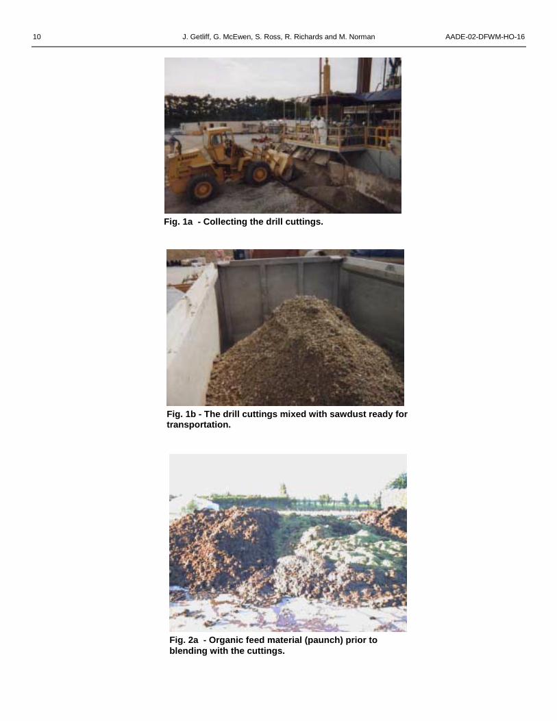
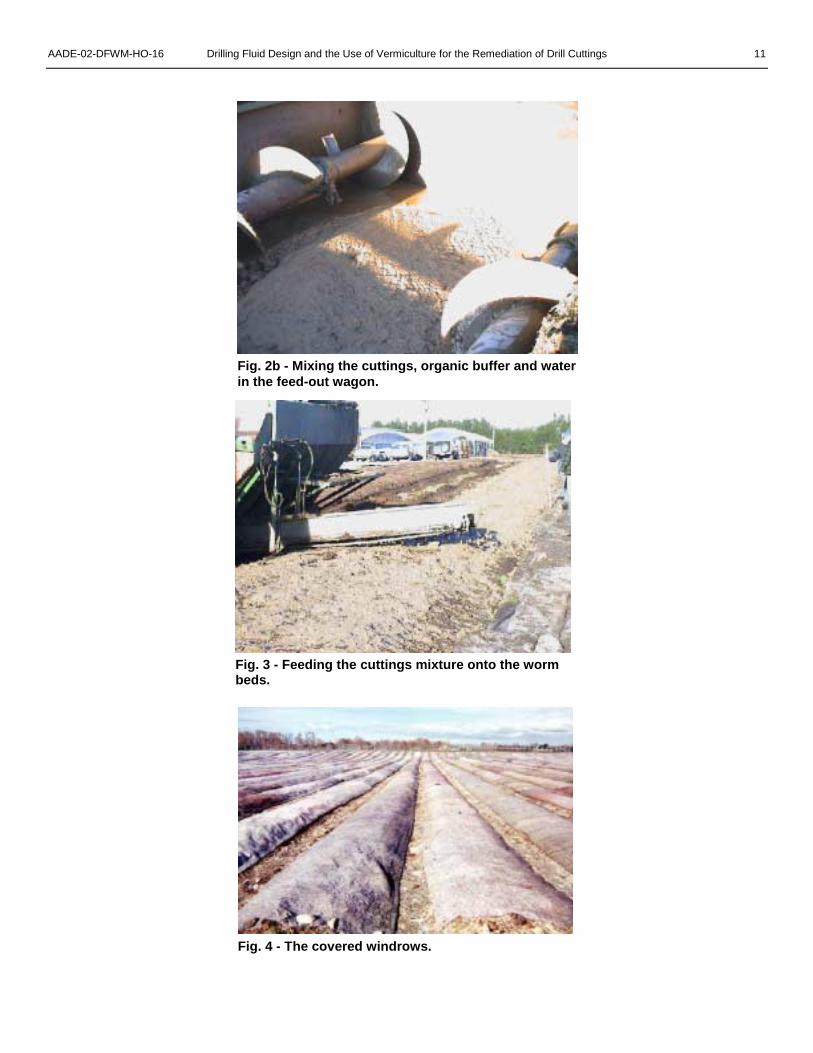
Drill Cuttings Waste ManagementDrill cuttings were mixed with sawdust (45% w/w;
Fig. 1a and b) to facilitate transport and then deliveredto the vermiculture site near New Plymouth, NewZealand where they were blended (Fig. 2a and b) withpaunch waste (undigested grass) from a slaughterhousebefore being fed to the worm beds using an agriculturalfeed-out wagon of the sort used for feeding silage tolivestock (Fig. 3).
Preparation of the Feed MixtureSuccessful degradation of organic materials by
worms is dependent upon maintaining optimalenvironmental conditions for the worms, the most
important parameters being the carbon/nitrogen ratio(25:1) and moisture content (75%).
The drill cuttings were blended and mixed with thepaunch material at variable ratios and then combinedwith water giving a 50:50 v/v water:solids slurry thatcould be evenly distributed from the feedout wagon.Blending and mixing of the drill cuttings, paunch wastes,green wastes and water was performed on a bundedconcrete pad that is approximately 30 m by 15 m indiameter, giving 450 m2 for controlled waste mixing. Themixing and was carried out in a Marmix combined mixingand feed-out wagon, the three internal augers of thetrailer being used to ensure thorough mixing.
Application to the Worm BedsOnce the blended material had been prepared it was
loaded into a watertight feed-out wagon for applicationas feedstock for the worms to process in moundsreferred to as windrows (Fig. 4). The windrows were 88m in length by 3 m wide. There are two meter-wideaccess tracks between each of the windrows for accessof the feed-out wagon to apply the mixed material, andalso to allow for ongoing maintenance of the windrowsand the subsequent vermiculture production processes.
The blended material was applied to the center/topof the windrows, usually once a week at an averagedepth of 15-30 mm. The exact application rate dependsupon climatic conditions and is higher in summer thanwinter. The worms “work” the top 100 mm of eachwindrow, consuming the applied material over a five- toseven-day period. Once the test materials had beenapplied, the worm beds were fed on a weekly to 10-daybasis with unamended paunch material as part of thenormal worm-driven waste-management routine carriedout at the site.
Maintenance of the Worm BedsEach of the windrows is covered completely by a
polypropylene-backed felt mat which excludes light fromthe worm bed and, although semi-permeable to water,the polypropylene backing deflects heavy rainfall awayfrom the surface of the bed and prevents the windrowfrom becoming waterlogged. This is important as itmaintains an optimal aerobic environment for the wormsto work in.
The windrows were also fitted with a controlledirrigation system that could be used to keep the coversmoist and maintain the correct moisture content duringperiods of low rainfall.
As the use of worms for degradation of the mixture isan aerobic process, the windrows are aerated prior toeach feeding procedure to ensure aerobic conditionswithin all of the beds and maintain optimal conditions forthe worms and their associated microbial processes.The aerator is attached to the power take-off linkage onthe tractor and side arms guide any material (vermicast)
4 J. Getliff, G. McEwen, S. Ross, R. Richards and M. Norman AADE-02-DFWM-HO-16
back onto the beds, ensuring no windrow exceeds thewidth to be covered by the felt mat.
Harvesting the VermicastOnce the worms have degraded the waste and
converted the applied material into vermicastings (wormcastings), the vermicast organic fertilizer is harvestedusing an industrial digger and is then packaged fordistribution and use on agricultural and horticultural landas a beneficial fertilizer and soil conditioner.
Vermicast ApplicationsVermicast is well known for its fertilizer properties5,6
and has applications within both agriculture andhorticulture, but it still remains to be seen what effect theinclusion of drill cuttings has on the fertilizer properties ofthe final product.
Experimental DesignCurrently three experiments have been performed to
evaluate the effect of worm farming on the remediationof drill cuttings.
The first experiment was a relatively simplefeasibility study, which looked for evidence of a decreasein hydrocarbon concentration in samples taken from aworm bed to which drill cuttings had been applied.
Norman, et al.4 discussed the results of this initialtest but it will also be reviewed in this paper to put theresults in full context. Following on from the firstexperiment, it was decided to perform a number of morecomprehensive experiments to further study the process.Two subsequent experiments have been carried out, thefirst during the antipodean winter, the second during theNew Zealand summer months.
The primary aim of the second experiment was torepeat the initial work under more defined conditions andstudy the effect of different cuttings application rates onthe process (Table 1).
In addition to monitoring hydrocarbon concentrationswithin the worm beds, a wide variety of soil chemistryparameters were also measured. As the barite weightmaterial contains a number of heavy metals andearthworms are known to be liable to bioaccumulatesuch materials,7-9 it was also decided to evaluate thefate of the heavy metals from the drilling fluid in theworm beds.
As the second experiment was carried out during theNew Zealand winter, under environmental conditionswhich do not favor high rates of activity by the earthworms, it was decided to repeat the experiment a thirdtime under more favorable (summer) environmentalconditions.
Because the two highest application rates used inthe previous experiment did not favor efficientremediation of the drill cuttings, the experiment wasrepeated using only the two lower application rates; 30%w/w drill cuttings and 50% w/w drill cuttings.
Sampling and Analytical Procedures
Initial Experiments50-mL grab samples were taken at time zero and
then at approximately weekly intervals throughout thecourse of the experiment. Samples were transported byovernight courier to the analytical laboratory in Hamilton,New Zealand where they were stored at 4°C prior toanalysis. The samples were analyzed for totalpetroleum hydrocarbons (TPH) content according to theNew Zealand Oil Industries Environmental WorkingGroup (OIEWG) guidelines and recommendations.10
Once in the laboratory, the samples were groundwith dry ice (Cryogrinding) prior to sub-sampling andsubsequent analysis. Samples for TPH determinationwere extracted using dichloromethane and sonication.The extracted samples were then dried with silica priorto analysis by GC-FID,10 the detection limit of theprocedure used by the laboratory being 60 mg/kg.
Second ExperimentTriplicate core samples were taken randomly and on
an approximately weekly basis from a (6-m x 3-m) sub-section of each of the 5 research windrows using 60-mmdiameter plastic core tubes. The core tubes werescrewed all the way to the base of the windrow toensured the sample contained any hydrocarbon materialthat might have migrated vertically down through thewindrow, either as a result of leaching or mechanical orbiological movement and transport
All samples were analyzed for TPH content withmore detailed soil chemistry and heavy metal analysis(Appendix 1) being performed on the time zero and 60-day (termination) samples to study the effect of theprocess on nutrient and heavy metal concentrations.
Seasonal variations in temperature were recorded,as they are climatic factors that could influence rates ofhydrocarbon degradation in the worm beds.
Third ExperimentInitially six core samples were taken from each of
the treatment areas (total sample weight approx 1 kg),and combined together at the test site in large mixingcontainer. The samples were then thoroughly mixedprior to removal of a 250 – 300-g composite sub-sample,which was sent for analysis. After five days, the appliedmaterial appeared to be well distributed across thewindrow and the number of core samples was reducedto four. The mixing and sub-sampling procedureremained the same.
All samples were analyzed for TPH content withmore detailed soil chemistry and heavy metal analysis(Appendix 1) being performed on the time zero andtermination samples to study the effect of the process onnutrient and heavy metal concentrations.
Seasonal variations in temperature were alsorecorded.
AADE-02-DFWM-HO-16 Drilling Fluid Design and the Use of Vermiculture for the Remediation of Drill Cuttings 5
Results
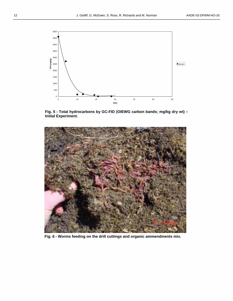
First ExperimentIn the initial experiment discussed in Norman, et al.,4
the hydrocarbon concentrations decreased from 4600mg /kg (dry wt) to less than 100 mg/kg (dry wt) in under28 days with less than 200 mg/kg (dry wt) remainingafter 10 days in what appears to be a fairly typicalexponential-type degradation curve (Fig. 5).
The bulk of the hydrocarbons detected werecomprised of C10 – C14 aliphatic hydrocarbons (Table 2),which is in good agreement with the carbon-chain-lengthdistribution of the C12 – C17 linear paraffin blend used inthis drilling fluid and indicates that there were no externalsources of contaminating hydrocarbons.
There was no detectable excess mortality amongstthe worms that were fed the drill cuttings and althoughthe numbers were not quantified, there appeared to be adefinite preference among the worms for the area wherethe cuttings and paunch feed had been applied. It is notclear if this was due to the hydrocarbons attracting theworms or the increased availability of easily assimilatedorganic carbon/microbial biomass that would beassociated with the highly biodegradable linear paraffinsof the drill cuttings.
It was also noted that there was complete physicaldegradation of the cuttings by the vermidigestionprocess and none of the original intact cuttings could befound, the original cuttings size being 5 –10 mm indiameter.
Second ExperimentAgain there was no visual mortality among the
treated earthworms and the hydrocarbon “fingerprint”matched the applied base fluid. It was also apparentthat the applied drill cuttings mix caused the worms toactively seek out the clumps on material containing drillcuttings (Fig. 6).
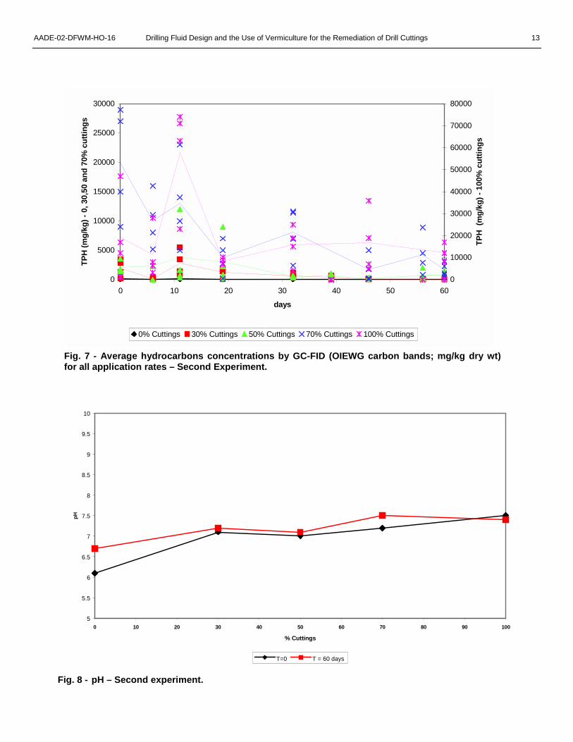
Total Petroleum HydrocarbonsFrom the results shown in Fig. 7, it can be seen that
the background hydrocarbon samples were around thedetection levels for the method for the duration of theexperiment indicating that there were no significantexternal sources of hydrocarbons being added to theworm beds apart from the test material
Due to the heterogeneous way in which the cuttingswere applied to the worm bed, some of the initialsamples taken were very variable and this is reflected inthe data points for the TPH results shown in Fig. 7.However taken overall, a number of general trends canbe seen.
The hydrocarbons in the cuttings applied at 30%w/w decreased from an average of 1900 mg/kg to lessthan 60 mg/kg within 45 days
The hydrocarbons in the cuttings applied at 50%
w/w decreased from an average of 2100 mg/kg to thedetection limit within 45 days but then showed a slightincrease for some, unknown reason, although it may berelated to the heterogeneity of the worm bed andsampling variation.
The hydrocarbons in the cuttings applied at 70%w/w showed quite a clear trend and decreased from anaverage of 20,000 mg/kg to 1500 mg/kg within 45 daysbut there was no subsequent reduction in thehydrocarbon concentration after this time.
After the initial degradation of the cuttings applied at70% w/w, it was found that the clumps of cuttings andfeed mixture within the worm bed had dried out andbecome compacted making them unpalatable to theworms. As the worms were no longer breaking down thecuttings, it is thought that the remaining degradation ismicrobially driven and is not expected to be particularlyfast given the unfavorable conditions for bacteria andlack of moisture within the cutting/feed mix clumps. Italso means that as the worm beds continued to be fedwith unamended paunch material, the worms feedingzone moved away from the cuttings. This furtherreduced the rate of hydrocarbon degradation, as theprocess is no longer being facilitated and accelerated bythe worms.
The hydrocarbons in the cuttings applied at 100%w/w (i.e. without any paunch amendments) did not showany obvious degradation throughout the course of theexperiment (60 days). It is thought that this is becausethe consistency of the cuttings (mixed with sawdust tofacilitate transport) combined with that lack of paunchmaterial (which constitutes a large part of the worm“normal” diet) makes the unamended mixture of cuttingsand sawdust very “unappealing” to the worms. Thismeans that the worms don’t eat the cuttings and therates of hydrocarbon degradation are much reduced.
Overall the rates of hydrocarbon degradation wereslower in the second experiment than in the first and thisis thought to be due to the prevailing weather andclimatic conditions.
The importance of the worms in enhancing the ratesof hydrocarbon degradation is shown by the muchslower rates of decrease in hydrocarbon concentration(Table 3) in samples of cuttings blended with paunchmaterial that were in parts of the windrow that wereinaccessible to the worms and were not tilled andaerated.
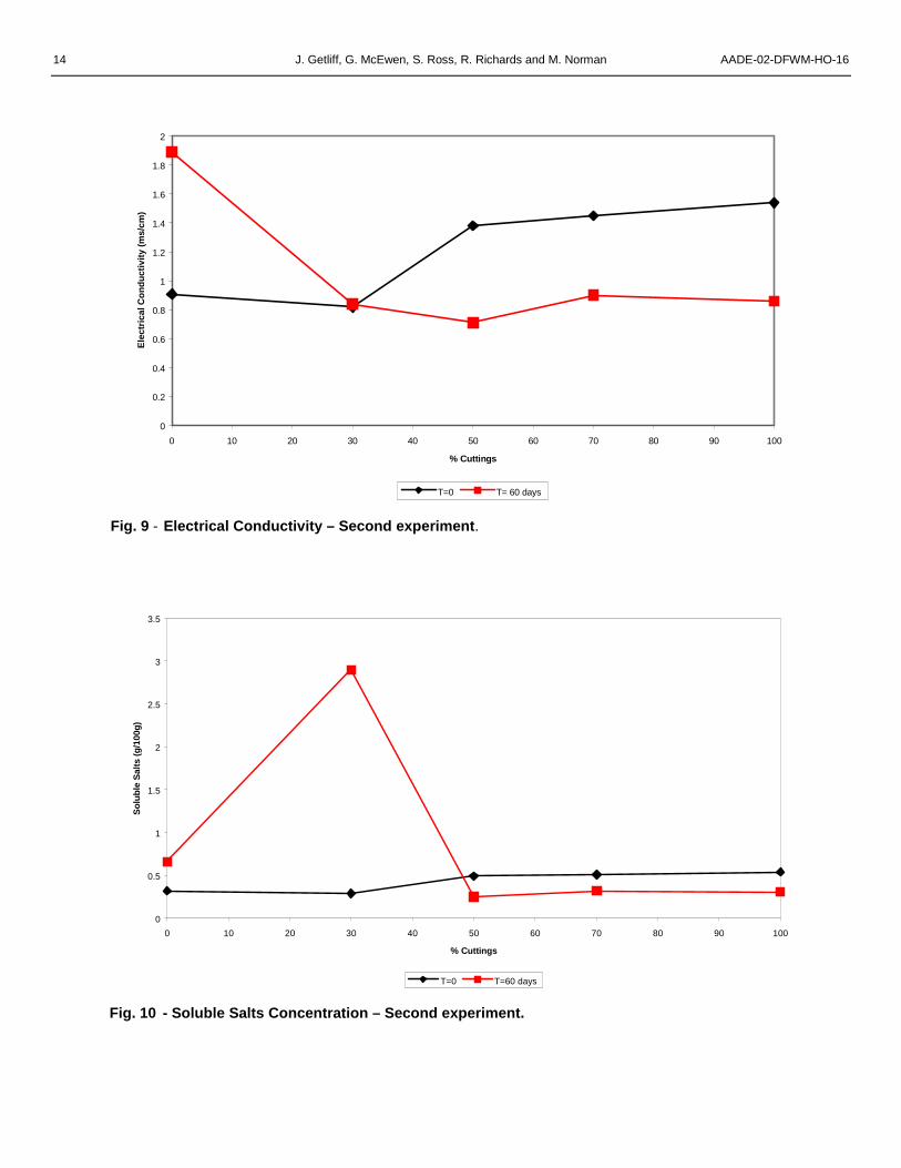
Soil ChemistryLooking at the pH data shown in Fig. 8, it can be
seen that there is slight increase in pH as more cuttingsare applied to the worm bed and that the pH tends to beslightly higher at the end of the experiment. This wouldbe caused by the slightly alkaline nature of the drillcuttings and base fluid and the release of the lime fromthe drilling fluid emulsion as it is broken down. Theincrease in pH is not sufficiently high as to adversely
6 J. Getliff, G. McEwen, S. Ross, R. Richards and M. Norman AADE-02-DFWM-HO-16
affect the earthworms.The remaining soil chemistry results (Figs. 9 – 14)
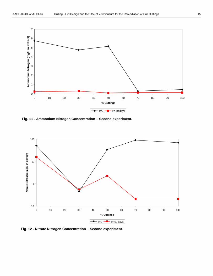
are not quite as easy to interpret.Electrical conductivity is a measure of the total salt
or ion content within the sample and can have significanteffects on soil properties such as the cation exchangecapacity, etc. From time zero on, the electricalconductivity can be seen to generally increase (Fig. 9)as more cuttings are applied. This probably reflects theuse of calcium ammonium nitrate in the brine phase ofthe drilling fluid; the more cuttings added the higher theelectrical conductivity. At the end of the experiment theelectrical conductivity is constant for all the windrows towhich drill cuttings were applied. This suggests thateither the bacteria or earthworms have utilized thecalcium ammonium nitrate in the remediation process. Itis not clear why the electrical conductivity in the control(no added drill cuttings) should differ at the start andfinish of the experiment. This trend is confirmed by theother soil chemistry data for nitrogen-containingmaterials (Figs. 11, 12 and 13).
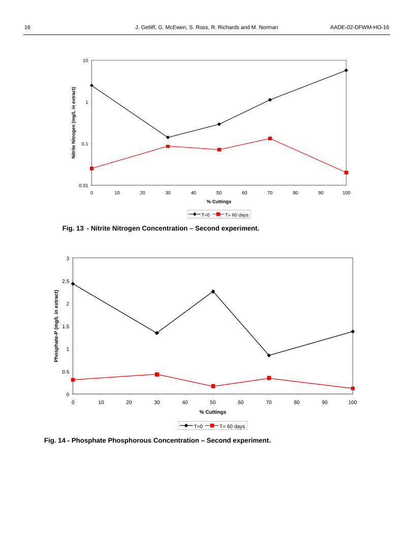
As mentioned previously, the nitrogen- andphosphorous-containing compounds, ammoniumnitrogen, nitrate nitrogen, nitrite nitrogen and phosphatephosphorous do not show readily discernable individualtrends (Figs. 11, 12, 13 and 14). However, takenoverall, it can be seen that the concentration of theseelements, which are essential for microbial degradationand growth11 decrease over the course of theexperiment as they are consumed by the bacteria andconverted into microbial and earthworm biomass as partof the degradation process.
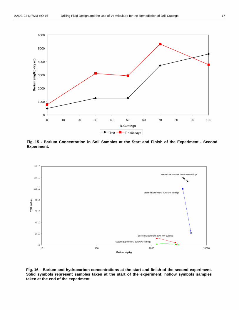
Heavy MetalsThe barium concentrations shown in Figs. 15 and
16 reflect the amount of drilling fluid and cuttings addedto the windrows (the barium is present as barium sulfatein the drilling fluid weight material) and were used as aconservative marker to ensure that the hydrocarbonswere being degraded within the cuttings pile and thatthere was no loss of the cuttings through physicalremoval.
Looking at the time zero barium concentrations inFig. 15, it can be seen that, as would be expected, asmore cuttings are added to the worm bed, the bariumconcentration increases. It is not clear why, after asingle application of drill cuttings, the bariumconcentration at the end of the experiment (T=60 days)should be higher than the initial starting concentration.Currently we do not have an explanation for thesephenomena, although it may be caused by improvedsample homogeneity as the worms broke down thepaunch and cuttings materials.
Whilst the barium concentrations for each of thewindrows remained broadly comparable at the start andfinish of the experiment, the hydrocarbon concentrationsin all but the 100% w/w cuttings addition showed a
marked decrease in TPH concentration (Fig. 16)indicating degradation of the hydrocarbons but nophysical loss of the drill cuttings from the windrows. Thisindicates that the cuttings were being degraded in theworm beds.
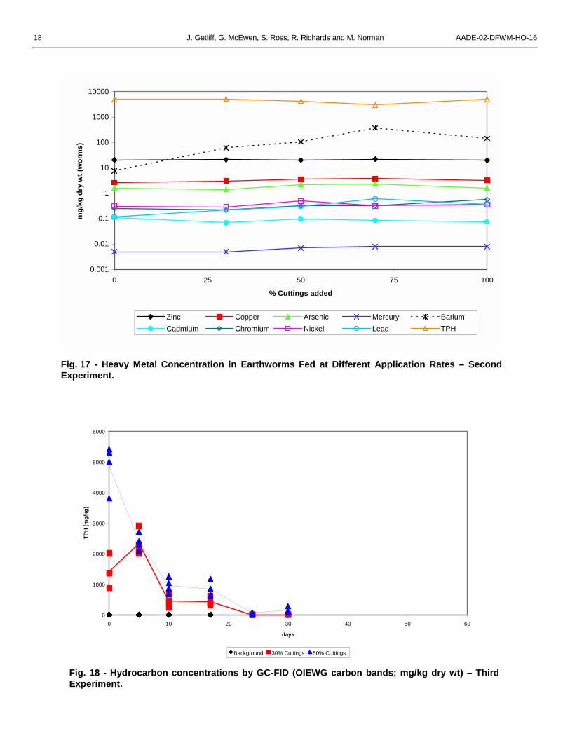
Heavy metal bioaccumulationAs earthworms are known to accumulate heavy
metals within their tissues,7-9 3-g samples of earthwormswere analyzed for heavy metal content at the end of theexperiment. Most of the metal concentrations remainfairly constant at the different cuttings application rates(Fig. 17). However, there is a slight increase in the leadconcentration within the earthworm tissues coupled witha more obvious increase in the barium concentration inthe 30%, 50% and & 70% w/w additions. It is interestingto note that the barium and lead levels show a slightdecrease at highest rate of addition (where there wasvery little biological “working” of the cuttings),presumably because the worms were not ingesting thecuttings in large amounts therefore there was lessbioaccumulation. This reduced rate of activity in the100% addition may also explain some of the othervariations in nutrient levels, etc.
Third ExperimentAs the climatic conditions for the winter experiment
did not favor maximum rates of degradation in the wormbeds and there were concerns about the variability ofsome of the TPH samples it was decided to repeat theexperiment a third time under more favorableenvironmental conditions using a composite samplingprocedure as discussed above.
Again there was no visual mortality of the worms andthey appeared to actively seek out the clumps of drillcuttings.
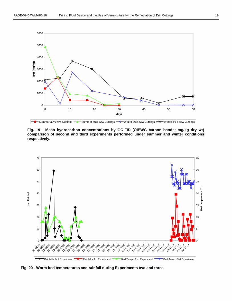
Total Petroleum HydrocarbonsAs in previous experiments no significant
background hydrocarbon concentrations were found(Fig. 18), whilst the 30 and 50% application ratesshowed significant degradation of hydrocarbons tobackground levels within 30 days (Fig. 18). The initialresults for the cuttings applied at 30% w/w aresomewhat misleading due to incorrect analyticalprocedures being used for these samples. The originalsamples from this treatment were incorrectly air dried at35°C, resulting in the loss of some of the volatilehydrocarbon fractions. However, in spite of this anomaly,a clear decrease in hydrocarbon concentration can stillbe seen.
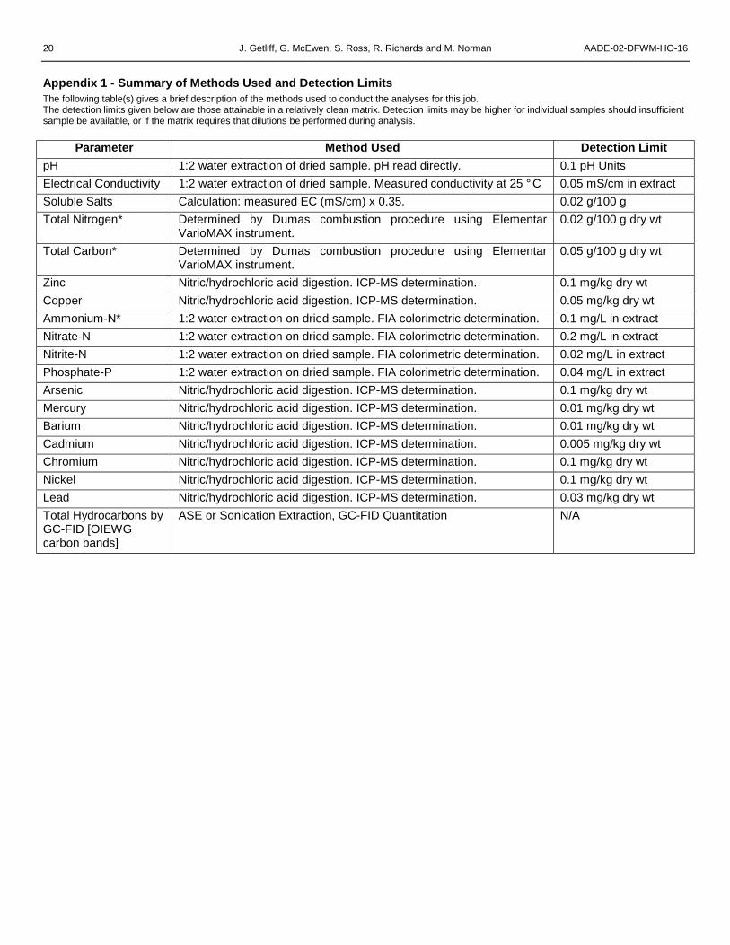
The increased rate of degradation for the thirdexperiment compared to the second experiment (Fig.19) show the advantages of favorable environmentalconditions, specifically the effect of the temperature inthe worm beds (Fig. 20), which is considerably higher in
AADE-02-DFWM-HO-16 Drilling Fluid Design and the Use of Vermiculture for the Remediation of Drill Cuttings 7
the New Zealand winter.
Soil ChemistryThe soil chemistry parameters for the third experi-
ment were also somewhat inconclusive (data notshown). There did appear to be similar trends to thoseobserved in the second experiment, i.e., a generaldecrease in the nitrogen- and phosphorous-containingcompounds as they are used up in the microbialdegradation process.
Heavy MetalsAs in the second experiment, barium concentrations
in the samples increased when drill cuttings wereapplied, but the limited number of samples analyzed forbarium at the start and finish of the experiment make itdifficult to draw any firm conclusions.
The worms did show an increase in a number ofheavy metals after feeding on material containing drillcuttings and barite weight material (Table 4) but it is notclear if the heavy metals were found in the worms gut ortissues even though the worms were fasted for 24 hoursbefore sampling in an attempt to remove the internalcastings before sampling. This length of time might notbe sufficient to purge the gut contents.
Conclusions• Results indicate, that under the correct
conditions, there is substantial degradation ofthe hydrocarbons within the worm bed, althoughat this point in time it is not yet clear exactlywhat the biological mechanism is.
• Factors such as temperature are known to havesignificant effects on worm husbandry and wereshown to effect rates of hydrocarbondegradation.
• As might be expected from our knowledge of themicrobial degradation of hydrocarbons, anumber of the more bioavailable soil nutrientssuch as nitrate and phosphate decreased as thehydrocarbons were degraded.
• Heavy metal concentrations in the resultingworm cast increased at higher application andfeeding rates and there is some indications ofheavy metal bioaccumulation, which requiresfurther study, or the use of alternative weightingmaterials.
• Good husbandry of the worms appears to be thekey to success of the process
• Cuttings additions of 30 — 50% appear to beoptimum. Any higher and the cuttings andhydrocarbons are less available to the worms orare unpalatable (100% w/w) and are notdegraded.
• Cuttings which are unpalatable to the worms willeventually become buried in the worm cast asmore food is applied to the worms beds andmove out of the feeding zone, forcing thedegradation to be purely microbial and henceslower if the conditions within the cuttings "pats"are unfavorable for microbial degradation.
• Given the amount of worms available for treatingorganic wastes at the treatment site, theapproximate amount of cuttings that can betreated at a 30% w/w feeding regime equates toabout 800 tonnes per month depending uponthe time of year.
• Optimum benefit is obtained from the synergisticuse of drilling fluids designed for bioremediationand vermiculture technology, the worms beingused to add value to the cleaned cuttings andfurther reducing disposal costs.
Future WorkThe worm farm in New Zealand is now routinely
adding 20% w/w drill cuttings to their worm beds andthere has not been any evidence of decline inconsumption rates or volumes with the combination ofcuttings, and no apparent detriment to the wormpopulation at this point in time
Although it can be seen from these results thathydrocarbons are degraded in the worm bed there stillremain a number of important questions to be answeredso that we can better understand the degradationprocess and fate of the heavy metals associated withthe drill cuttings.
We need a better knowledge of the way in which thehydrocarbons are degraded in the worm beds. Possiblehypothesis include microbial degradation within theworm beds, favorable aerobic conditions beinggenerated by the burrowing and mixing activities of theworms; metabolism of the hydrocarbons by the worms; asymbiotic relationship between the bacteria in theearthworm gut degrading the hydrocarbons on theingested cutting particles, or perhaps a combination ofthese mechanisms.
We need to better understand the effect of theprocess on the fate of the heavy metals associated withthe cuttings and their impact on the final quality of theworm cast.
It is also important that we further develop oursampling and analysis procedures so as to betterconfirm degradation of the hydrocarbons and fullyunderstand their fate.
As worm cast has been shown to have beneficialproperties as an agricultural fertilizer, we also propose toperform further studies to determine the role of the claysand minerals present in the cleaned drill cuttings mayhave on the horticultural properties of the worm cast.
8 J. Getliff, G. McEwen, S. Ross, R. Richards and M. Norman AADE-02-DFWM-HO-16
AcknowledgmentsThe authors thank the many people at Global
Vermiculture and within M-I for their help in undertakingthis research.
References1. Curtis, G.W., Growcock, F.B., Candler, J.E., Rabke, S.P.,
and Getliffe, J.: Can synthetic-based muds be designed toenhance soil quality? AADE-01-NC-HO-11, AADENational Drilling Conference ‘Drilling Technology – TheNext 100 Years’, Houston, Mar 27-29, 2001.
2. Growcock, F.B., Curtis, G.W., Hoxha, B., Brooks, S. andCandler, J.E.: “Designing Invert Drilling Fluids to YieldEnvironmentally Friendly Drill Cuttings,” SPE 74474,IADC/SPE Drilling Conference, Dallas, Feb 26-28, 2002.
3. Visser, S.: “Biodegradability and Ecotoxicity of Six BaseFluids Being Considered for Drilling Mud Production,”Confidential Report, Dept. Biological Sciences, Univ. ofCalgary, Calgary, Canada (2000).
4. Norman, M., Ross, S., McEwen, G. and Getliff, J.:“Minimizing Environmental Impacts and Maximizing HoleStability; Significance of Drilling with Synthetic Fluids inNZ,” New Zealand Petroleum Conference, Auckland, NewZealand, Feb 24-27, 2002.
5. Atiyeh, R.M., Subler, S., and Edwards, C.S.: “Growth ofTomato Plants in Horticultural Potting Media Amendedwith Vermicompost. Pedobiologia (1999) 43: 1-5.
6. Edwards, C. & Burrows I.: “The Potential of EarthwormComposts as Plant Growth Media,” In: Earthworms inWaste and Environmental Management,” by Edwards,C.A. and Neuhausen, E.F.; SPB Academic Publishing,The Hague (1998).
7. Buchanan, M.A.: “Chemical Characterisation and NitrogenMineralisation Potentials of Vermicomposts,” In:Earthworms in Waste and Environmental Management,”by Edwards, C.A. and Neuhausen, E.F.; SPB AcademicPublishing, The Hague (1998).
8. Sample, B. E., Suter, G. W., II, Beauchamp, J. J. andEfroymson, R. A.: “Literature-Derived BioaccumulationModels for Earthworms: Development and Validation,”Environmental Toxicology & Chemistry (1991) 18:2110-2120.
9. Corp, N. and Morgan, A. J. “Accumulation of HeavyMetals from Polluted Soils by the Earthworm Lumbricusrubellus,” Environmental Pollution (1991) 74: 39-52.
10. Oil Industry Environmental Working Group: “DraftSampling Protocols and Analytical Methods forDetermining Petroleum Products in Soil and Water,” NewZealand Ministry for the Environment (May 1999).
11. Brock, T.D. & Madigan, M.T.: The Biology ofMicroorganisms, 6th ed.; Prentice-Hall, London (1991).
AADE-02-DFWM-HO-16 Drilling Fluid Design and the Use of Vermiculture for the Remediation of Drill Cuttings 9
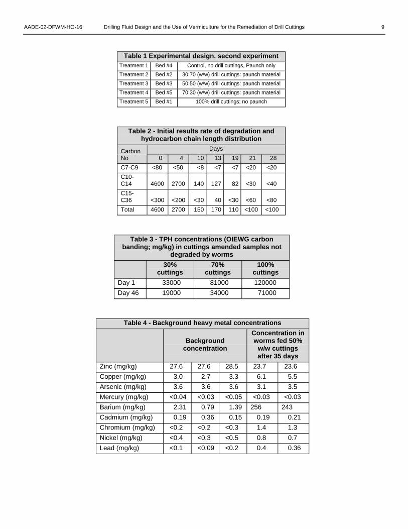
Table 1 Experimental design, second experimentTreatment 1 Bed #4 Control, no drill cuttings, Paunch onlyTreatment 2 Bed #2 30:70 (w/w) drill cuttings: paunch materialTreatment 3 Bed #3 50:50 (w/w) drill cuttings: paunch materialTreatment 4 Bed #5 70:30 (w/w) drill cuttings: paunch materialTreatment 5 Bed #1 100% drill cuttings; no paunch
Table 2 - Initial results rate of degradation andhydrocarbon chain length distribution
DaysCarbonNo 0 4 10 13 19 21 28C7-C9 <80 <50 <8 <7 <7 <20 <20C10-C14 4600 2700 140 127 82 <30 <40C15-C36 <300 <200 <30 40 <30 <60 <80Total 4600 2700 150 170 110 <100 <100
Table 3 - TPH concentrations (OIEWG carbonbanding; mg/kg) in cuttings amended samples not
degraded by worms30%
cuttings70%
cuttings100%
cuttingsDay 1 33000 81000 120000Day 46 19000 34000 71000
Table 4 - Background heavy metal concentrations
Backgroundconcentration
Concentration inworms fed 50%
w/w cuttingsafter 35 days
Zinc (mg/kg) 27.6 27.6 28.5 23.7 23.6Copper (mg/kg) 3.0 2.7 3.3 6.1 5.5Arsenic (mg/kg) 3.6 3.6 3.6 3.1 3.5Mercury (mg/kg) <0.04 <0.03 <0.05 <0.03 <0.03Barium (mg/kg) 2.31 0.79 1.39 256 243Cadmium (mg/kg) 0.19 0.36 0.15 0.19 0.21Chromium (mg/kg) <0.2 <0.2 <0.3 1.4 1.3Nickel (mg/kg) <0.4 <0.3 <0.5 0.8 0.7Lead (mg/kg) <0.1 <0.09 <0.2 0.4 0.36
10 J. Getliff, G. McEwen, S. Ross, R. Richards and M. Norman AADE-02-DFWM-HO-16
Fig. 1a - Collecting the drill cuttings.
Fig. 1b - The drill cuttings mixed with sawdust ready fortransportation.
Fig. 2a - Organic feed material (paunch) prior toblending with the cuttings.
AADE-02-DFWM-HO-16 Drilling Fluid Design and the Use of Vermiculture for the Remediation of Drill Cuttings 11
Fig. 2b - Mixing the cuttings, organic buffer and waterin the feed-out wagon.
Fig. 3 - Feeding the cuttings mixture onto the wormbeds.
Fig. 4 - The covered windrows.
12 J. Getliff, G. McEwen, S. Ross, R. Richards and M. Norman AADE-02-DFWM-HO-16
0
500
1000
1500
2000
2500
3000
3500
4000
4500
5000
0 10 20 30 40 50 60
days
TPH
(mg/
kg)
Series1
Fig. 5 - Total hydrocarbons by GC-FID (OIEWG carbon bands; mg/kg dry wt) –Initial Experiment.
Fig. 6 - Worms feeding on the drill cuttings and organic ammendments mix.
AADE-02-DFWM-HO-16 Drilling Fluid Design and the Use of Vermiculture for the Remediation of Drill Cuttings 13
0
5000
10000
15000
20000
25000
30000
0 10 20 30 40 50 60
days
TPH
(mg/
kg) -
0, 3
0,50
and
70%
cut
tings
0
10000
20000
30000
40000
50000
60000
70000
80000
TPH
(m
g/kg
) - 1
00%
cut
tings
0% Cuttings 30% Cuttings 50% Cuttings 70% Cuttings 100% Cuttings
Fig. 7 - Average hydrocarbons concentrations by GC-FID (OIEWG carbon bands; mg/kg dry wt)for all application rates – Second Experiment.
5
5.5
6
6.5
7
7.5
8
8.5
9
9.5
10
0 10 20 30 40 50 60 70 80 90 100
% Cuttings
pH
T=0 T = 60 days
Fig. 8 - pH – Second experiment.
14 J. Getliff, G. McEwen, S. Ross, R. Richards and M. Norman AADE-02-DFWM-HO-16
0
0.2
0.4
0.6
0.8
1
1.2
1.4
1.6
1.8
2
0 10 20 30 40 50 60 70 80 90 100
% Cuttings
Elec
tric
al C
ondu
ctiv
ity (m
s/cm
)
T=0 T= 60 days
Fig. 9 - Electrical Conductivity – Second experiment.
0
0.5
1
1.5
2
2.5
3
3.5
0 10 20 30 40 50 60 70 80 90 100
% Cuttings
Solu
ble
Salts
(g/1
00g)
T=0 T=60 days
Fig. 10 - Soluble Salts Concentration – Second experiment.
AADE-02-DFWM-HO-16 Drilling Fluid Design and the Use of Vermiculture for the Remediation of Drill Cuttings 15
0
1
2
3
4
5
6
7
0 10 20 30 40 50 60 70 80 90 100
% Cuttings
Am
mon
ium
Nitr
ogen
(mg/
L in
ext
ract
)
T=0 T= 60 days
Fig. 11 - Ammonium Nitrogen Concentration – Second experiment.
0.1
1
10
100
0 10 20 30 40 50 60 70 80 90 100
% Cuttings
Nitr
ate
Nitr
ogen
(mg/
L in
ext
ract
)
T=0 T= 60 days
Fig. 12 - Nitrate Nitrogen Concentration – Second experiment.
16 J. Getliff, G. McEwen, S. Ross, R. Richards and M. Norman AADE-02-DFWM-HO-16
0.01
0.1
1
10
0 10 20 30 40 50 60 70 80 90 100
% Cuttings
Nitr
ite N
itrog
en (m
g/L
in e
xtra
ct)
T=0 T= 60 days
Fig. 13 - Nitrite Nitrogen Concentration – Second experiment.
0
0.5
1
1.5
2
2.5
3
0 10 20 30 40 50 60 70 80 90 100
% Cuttings
Phos
phat
e-P
(mg/
L in
ext
ract
)
T=0 T= 60 days
Fig. 14 - Phosphate Phosphorous Concentration – Second experiment.
AADE-02-DFWM-HO-16 Drilling Fluid Design and the Use of Vermiculture for the Remediation of Drill Cuttings 17
0
1000
2000
3000
4000
5000
6000
0 10 20 30 40 50 60 70 80 90 100
% Cuttings
Bar
ium
(mg/
kg d
ry w
t)
T=0 T = 60 days
Fig. 15 - Barium Concentration in Soil Samples at the Start and Finish of the Experiment - SecondExperiment.
10
2010
4010
6010
8010
10010
12010
14010
10 100 1000 10000
Barium mg/kg
TPH
mg/
kg
Second Experiment, 70% w/w cuttings
Second Experiment, 100% w/w cuttings
Second Experiment, 50% w/w cuttings
Second Experiment, 30% w/w cuttings
Fig. 16 - Barium and hydrocarbon concentrations at the start and finish of the second experiment.Solid symbols represent samples taken at the start of the experiment; hollow symbols samplestaken at the end of the experiment.
18 J. Getliff, G. McEwen, S. Ross, R. Richards and M. Norman AADE-02-DFWM-HO-16
0.001
0.01
0.1
1
10
100
1000
10000
0 25 50 75 100
% Cuttings added
mg/
kg d
ry w
t (w
orm
s)
Zinc Copper Arsenic Mercury BariumCadmium Chromium Nickel Lead TPH
Fig. 17 - Heavy Metal Concentration in Earthworms Fed at Different Application Rates – SecondExperiment.
0
1000
2000
3000
4000
5000
6000
0 10 20 30 40 50 60
days
TPH
(mg/
kg)
Background 30% Cuttings 50% Cuttings
Fig. 18 - Hydrocarbon concentrations by GC-FID (OIEWG carbon bands; mg/kg dry wt) – ThirdExperiment.
AADE-02-DFWM-HO-16 Drilling Fluid Design and the Use of Vermiculture for the Remediation of Drill Cuttings 19
0
1000
2000
3000
4000
5000
6000
0 10 20 30 40 50 60
days
TPH
(mg/
kg)
Summer 30% w/w Cuttings Summer 50% w/w Cuttings Winter 30% w/w Cuttings Winter 50% w/w Cuttings
Fig. 19 - Mean hydrocarbon concentrations by GC-FID (OIEWG carbon bands; mg/kg dry wt)comparison of second and third experiments performed under summer and winter conditionsrespectively.
0
10
20
30
40
50
60
70
01-06
-01
08-06
-01
15-06
-01
22-06
-01
29-06
-01
06-07
-01
13-07
-01
20-07
-01
27-07
-01
03-08
-01
10-08
-01
17-08
-01
24-08
-01
31-08
-01
07-09
-01
14-09
-01
21-09
-01
28-09
-01
05-10
-01
12-10
-01
19-10
-01
26-10
-01
02-11
-01
09-11
-01
16-11
-01
23-11
-01
30-11
-01
07-12
-01
14-12
-01
21-12
-01
28-12
-01
mm
Rai
nfal
l
0
5
10
15
20
25
30
35
Bed
tem
pera
ture
°C
Rainfall - 2nd Experiment Rainfall - 3rd Experiment Bed Temp - 2nd Experiment Bed Temp - 3rd Experiment
Fig. 20 - Worm bed temperatures and rainfall during Experiments two and three.
20 J. Getliff, G. McEwen, S. Ross, R. Richards and M. Norman AADE-02-DFWM-HO-16
Appendix 1 - Summary of Methods Used and Detection LimitsThe following table(s) gives a brief description of the methods used to conduct the analyses for this job.The detection limits given below are those attainable in a relatively clean matrix. Detection limits may be higher for individual samples should insufficientsample be available, or if the matrix requires that dilutions be performed during analysis.
Parameter Method Used Detection LimitpH 1:2 water extraction of dried sample. pH read directly. 0.1 pH UnitsElectrical Conductivity 1:2 water extraction of dried sample. Measured conductivity at 25 ° C 0.05 mS/cm in extractSoluble Salts Calculation: measured EC (mS/cm) x 0.35. 0.02 g/100 gTotal Nitrogen* Determined by Dumas combustion procedure using Elementar
VarioMAX instrument.0.02 g/100 g dry wt
Total Carbon* Determined by Dumas combustion procedure using ElementarVarioMAX instrument.
0.05 g/100 g dry wt
Zinc Nitric/hydrochloric acid digestion. ICP-MS determination. 0.1 mg/kg dry wtCopper Nitric/hydrochloric acid digestion. ICP-MS determination. 0.05 mg/kg dry wtAmmonium-N* 1:2 water extraction on dried sample. FIA colorimetric determination. 0.1 mg/L in extractNitrate-N 1:2 water extraction on dried sample. FIA colorimetric determination. 0.2 mg/L in extractNitrite-N 1:2 water extraction on dried sample. FIA colorimetric determination. 0.02 mg/L in extractPhosphate-P 1:2 water extraction on dried sample. FIA colorimetric determination. 0.04 mg/L in extractArsenic Nitric/hydrochloric acid digestion. ICP-MS determination. 0.1 mg/kg dry wtMercury Nitric/hydrochloric acid digestion. ICP-MS determination. 0.01 mg/kg dry wtBarium Nitric/hydrochloric acid digestion. ICP-MS determination. 0.01 mg/kg dry wtCadmium Nitric/hydrochloric acid digestion. ICP-MS determination. 0.005 mg/kg dry wtChromium Nitric/hydrochloric acid digestion. ICP-MS determination. 0.1 mg/kg dry wtNickel Nitric/hydrochloric acid digestion. ICP-MS determination. 0.1 mg/kg dry wtLead Nitric/hydrochloric acid digestion. ICP-MS determination. 0.03 mg/kg dry wtTotal Hydrocarbons byGC-FID [OIEWGcarbon bands]
ASE or Sonication Extraction, GC-FID Quantitation N/A