Embed Size (px)
Citation preview
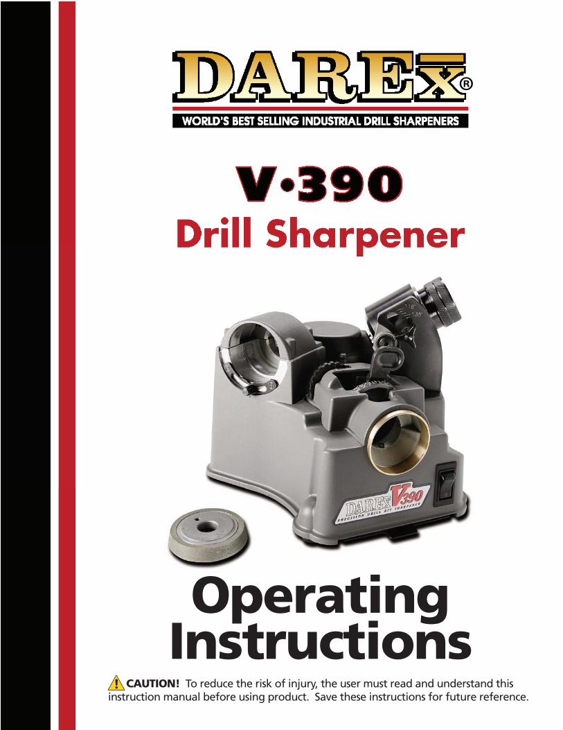
DAREX V390Drill Sharpener
1/8” (3mm) to ¾” (19mm) size range
OPERATINGINSTRUCTIONS
PP11852KF 03/20/06
®
CAUTION! To reduce the risk of injury, the user must read and understand thisinstruction manual before using product. Save these instructions for future reference.
OperatingInstructions
2
Table of Contents
The Darex Story......................................................................................... Page 3Safety Instructions..................................................................................... Page 4Getting to Know Your V391......................................................................... Page 5Drill Information......................................................................................... Page 6Quick Step Instructions............................................................................... Page 7-8Detailed Operating Instructions.................................................................... Page 9-11Machine Adjustments.................................................................................. Page 12-13Troubleshooting.......................................................................................... Page 14-15Maintenance Instructions............................................................................. Page 16-17Drawings & Parts List.................................................................................. Page 18-19
3
The Darex Story
Darex Corporation began in 1973 in Beecher, Illinois. The D, A and R of Darex are the initials of three generations of the Bernard family; David, Arthur and Richard Bernard. David and his father Richard founded Darex. Grandfather Arthur Bernard, who earlier founded the Bernard Welding Company contributed his energy and guidance to Darex until his death. Art’s inventions revolutionized the welding industry.
In 1978, Darex relocated to Ashland, Oregon. Grandson Dave and son Dick carry on Arthur’s legacy of inventiveness. Darex grew to become the most recognized name in the cutting tool sharpening industry. Today, Darex is a world-leading manufacturer of precision cutting tool sharpeners.
Darex is proud to offer a complete line of quality precision cutting tool sharpeners at affordable prices. Before our first days, we at Darex had looked at our competitor’s sharpeners and asked ourselves: ”Must cutting tool sharpeners be complicated? Why must the choice in sharpeners have either cost prohibitive accuracy or low price inaccuracy?” Our sharpeners prove you can have it all: simplicity, accuracy and affordability.
We have always emphasized innovative product design and tested technology. The experienced personnel at our modern manufacturing facility use the latest production methods. The Darex marketing team knows first-hand the machines we sell and will guide you to the best machine for your needs. Our skilled technical service department is happy to answer your questions about our products or cutting tools.
The V390
This limited duty unit is the most economically priced of the Darex Industrial Sharpeners. It is designed for the small fabrication or job-shop where a lower volume of drill sharpening is required. Point angle range is 118 to 140 degrees. Size range is 1/8” to ¾” (3mm to 19mm). This sharpener has point splitting capabilities. With the standard electroplated CBN (Cubic Boron Nitride) grinding wheel the V390 will sharpen high-speed steel, cobalt, parabolic, TiN and other coated drill bits. An electroplated diamond wheel is available to sharpen carbide drill bits. The electroplated diamond and CBN wheel will sharpen approximately 1000-2000 drills before replacement is required. The Darex V390 is most efficient when used to sharpen drill bits to their original point angle. The troubleshooting section of this manual is designed to anticipate many common questions and applications. To keep your DAREX V390 in top condition, please refer to the maintenance section of this manual. A complete schematic breakdown, replacement wheels and parts are listed on page 18 and 19.
4
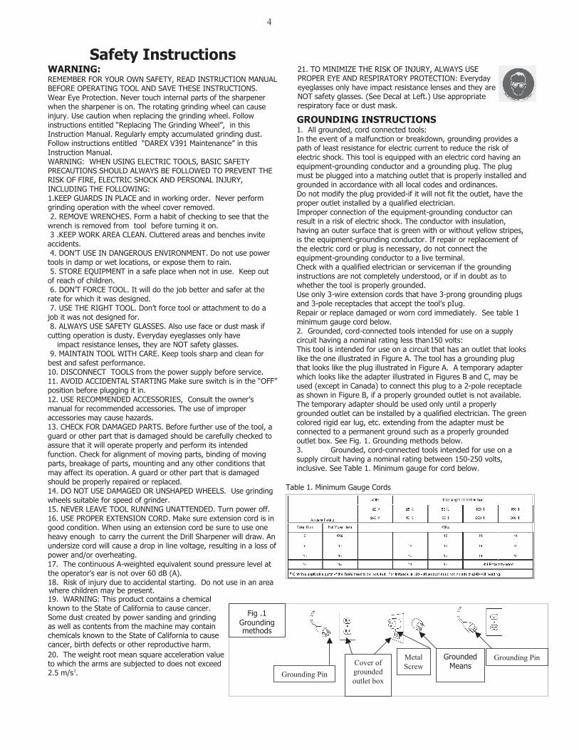
Safety Instructions WARNING: REMEMBER FOR YOUR OWN SAFETY, READ INSTRUCTION MANUAL BEFORE OPERATING TOOL AND SAVE THESE INSTRUCTIONS. Wear Eye Protection. Never touch internal parts of the sharpener when the sharpener is on. The rotating grinding wheel can cause injury. Use caution when replacing the grinding wheel. Follow instructions entitled “Replacing The Grinding Wheel”, in this Instruction Manual. Regularly empty accumulated grinding dust. Follow instructions entitled “DAREX V391 Maintenance” in this Instruction Manual. WARNING: WHEN USING ELECTRIC TOOLS, BASIC SAFETY PRECAUTIONS SHOULD ALWAYS BE FOLLOWED TO PREVENT THE RISK OF FIRE, ELECTRIC SHOCK AND PERSONAL INJURY, INCLUDING THE FOLLOWING: 1.KEEP GUARDS IN PLACE and in working order. Never perform grinding operation with the wheel cover removed. 2. REMOVE WRENCHES. Form a habit of checking to see that the wrench is removed from tool before turning it on. 3 .KEEP WORK AREA CLEAN. Cluttered areas and benches invite accidents. 4. DON’T USE IN DANGEROUS ENVIRONMENT. Do not use power tools in damp or wet locations, or expose them to rain. 5. STORE EQUIPMENT in a safe place when not in use. Keep out of reach of children. 6. DON’T FORCE TOOL. It will do the job better and safer at the rate for which it was designed. 7. USE THE RIGHT TOOL. Don’t force tool or attachment to do a job it was not designed for. 8. ALWAYS USE SAFETY GLASSES. Also use face or dust mask if cutting operation is dusty. Everyday eyeglasses only have impact resistance lenses, they are NOT safety glasses. 9. MAINTAIN TOOL WITH CARE. Keep tools sharp and clean for best and safest performance. 10. DISCONNECT TOOLS from the power supply before service. 11. AVOID ACCIDENTAL STARTING Make sure switch is in the “OFF” position before plugging it in. 12. USE RECOMMENDED ACCESSORIES, Consult the owner’s manual for recommended accessories. The use of improper accessories may cause hazards. 13. CHECK FOR DAMAGED PARTS. Before further use of the tool, a guard or other part that is damaged should be carefully checked to assure that it will operate properly and perform its intended function. Check for alignment of moving parts, binding of moving parts, breakage of parts, mounting and any other conditions that may affect its operation. A guard or other part that is damaged should be properly repaired or replaced. 14. DO NOT USE DAMAGED OR UNSHAPED WHEELS. Use grinding wheels suitable for speed of grinder. 15. NEVER LEAVE TOOL RUNNING UNATTENDED. Turn power off. 16. USE PROPER EXTENSION CORD. Make sure extension cord is in good condition. When using an extension cord be sure to use one heavy enough to carry the current the Drill Sharpener will draw. An undersize cord will cause a drop in line voltage, resulting in a loss of power and/or overheating. 17. The continuous A-weighted equivalent sound pressure level at the operator’s ear is not over 60 dB (A). 1
19. WARNING: This product contains a chemicalknown to the State of California to cause cancer.Some dust created by power sanding and grindingas well as contents from the machine may containchemicals known to the State of California to causecancer, birth defects or other reproductive harm.20. The weight root mean square acceleration valueto which the arms are subjected to does not exceed2.5 m/s .2
8. Risk of injury due to accidental starting. Do not use in an area where children may be present.
21. TO MINIMIZE THE RISK OF INJURY, ALWAYS USEPROPER EYE AND RESPIRATORY PROTECTION: Everydayeyeglasses only have impact resistance lenses and they areNOT safety glasses. (See Decal at Left.) Use appropriaterespiratory face or dust mask.
GROUNDING INSTRUCTIONS1. All grounded, cord connected tools: In the event of a malfunction or breakdown, grounding provides a path of least resistance for electric current to reduce the risk of electric shock. This tool is equipped with an electric cord having an equipment-grounding conductor and a grounding plug. The plug must be plugged into a matching outlet that is properly installed and grounded in accordance with all local codes and ordinances. Do not modify the plug provided-if it will not fit the outlet, have the proper outlet installed by a qualified electrician. Improper connection of the equipment-grounding conductor can result in a risk of electric shock. The conductor with insulation, having an outer surface that is green with or without yellow stripes, is the equipment-grounding conductor. If repair or replacement of the electric cord or plug is necessary, do not connect the equipment-grounding conductor to a live terminal. Check with a qualified electrician or serviceman if the grounding instructions are not completely understood, or if in doubt as to whether the tool is properly grounded. Use only 3-wire extension cords that have 3-prong grounding plugs and 3-pole receptacles that accept the tool’s pIug. Repair or replace damaged or worn cord immediately. See table 1 minimum gauge cord below. 2. Grounded, cord-connected tools intended for use on a supply circuit having a nominal rating less than150 volts: This tool is intended for use on a circuit that has an outlet that looks like the one illustrated in Figure A. The tool has a grounding plug that looks like the plug illustrated in Figure A. A temporary adapter which looks like the adapter illustrated in Figures B and C, may be used (except in Canada) to connect this plug to a 2-pole receptacle as shown in Figure B, if a properly grounded outlet is not available. The temporary adapter should be used only until a properly grounded outlet can be installed by a qualified electrician. The green colored rigid ear lug, etc. extending from the adapter must be connected to a permanent ground such as a properly grounded outlet box. See Fig. 1. Grounding methods below. 3. Grounded, cord-connected tools intended for use on a supply circuit having a nominal rating between 150-250 volts, inclusive. See Table 1. Minimum gauge for cord below.
Table 1. Minimum Gauge Cords
Fig .1 Grounding methods
Grounded Means Cover of
grounded outlet box
Grounding Pin
Grounding PinMetal Screw
5
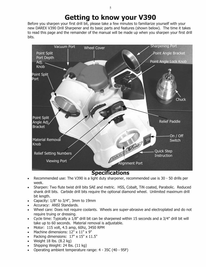
SpecificationsRecommended use: The V390 is a light duty sharpener, recommended use is 30 - 50 drills per week.Sharpen: Two flute twist drill bits SAE and metric. HSS, Cobalt, TiN coated, Parabolic. Reduced shank drill bits. Carbide drill bits require the optional diamond wheel. Unlimited maximum drill bit length. Capacity: 1/8" to 3/4", 3mm to 19mmAccuracy: ANSI Standards. Wheel care: Does not require coolants. Wheels are super-abrasive and electroplated and do not require truing or dressing. Cycle time: Typically a 1/8" drill bit can be sharpened within 15 seconds and a 3/4" drill bit will take up to 60 seconds. Material removal is adjustable. Motor: 115 volt, 4.5 amp, 60hz, 3450 RPMMachine dimensions: 12" x 11" x 9" Packing dimensions: 17" x 15" x 11.5" Weight 18 lbs. (8.2 kg) Shipping Weight: 24 lbs. (11 kg) Operating ambient temperature range: 4 - 35C (40 - 95F)
Getting to know your V390 Before you sharpen your first drill bit, please take a few minutes to familiarize yourself with your new DAREX V390 Drill Sharpener and its basic parts and features (shown below). The time it takes to read this page and the remainder of the manual will be made up when you sharpen your first drill bits.
Wheel Cover Vacuum Port
Point Split Port Depth Adj.Knob
Point Split Port
Point Split Angle Adj. Bracket
Material Removal Knob
Relief Setting Numbers
Viewing Port Alignment Port
Quick Step Instruction
On / Off Switch
Relief Paddle
Chuck
Point Angle Lock Knob
Point Angle Bracket
Sharpening Port
6
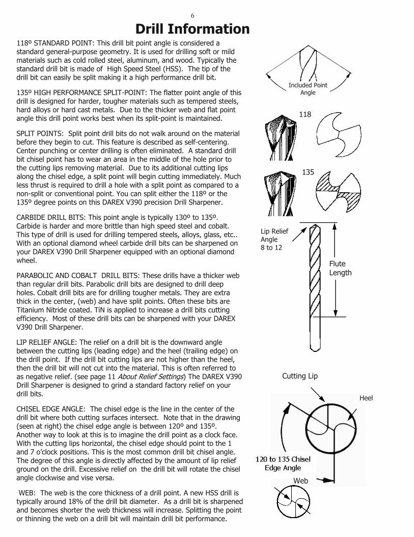
118º STANDARD POINT: This drill bit point angle is considered a standard general-purpose geometry. It is used for drilling soft or mild materials such as cold rolled steel, aluminum, and wood. Typically the standard drill bit is made of High Speed Steel (HSS). The tip of the drill bit can easily be split making it a high performance drill bit.
135º HIGH PERFORMANCE SPLIT-POINT: The flatter point angle of this drill is designed for harder, tougher materials such as tempered steels, hard alloys or hard cast metals. Due to the thicker web and flat point angle this drill point works best when its split-point is maintained.
SPLIT POINTS: Split point drill bits do not walk around on the material before they begin to cut. This feature is described as self-centering. Center punching or center drilling is often eliminated. A standard drill bit chisel point has to wear an area in the middle of the hole prior to the cutting lips removing material. Due to its additional cutting lips along the chisel edge, a split point will begin cutting immediately. Much less thrust is required to drill a hole with a split point as compared to a non-split or conventional point. You can split either the 118º or the 135º degree points on this DAREX V390 precision Drill Sharpener.
CARBIDE DRILL BITS: This point angle is typically 130º to 135º. Carbide is harder and more brittle than high speed steel and cobalt. This type of drill is used for drilling tempered steels, alloys, glass, etc.. With an optional diamond wheel carbide drill bits can be sharpened on your DAREX V390 Drill Sharpener equipped with an optional diamond wheel.
PARABOLIC AND COBALT DRILL BITS: These drills have a thicker web than regular drill bits. Parabolic drill bits are designed to drill deep holes. Cobalt drill bits are for drilling tougher metals. They are extra thick in the center, (web) and have split points. Often these bits are Titanium Nitride coated. TiN is applied to increase a drill bits cutting efficiency. Most of these drill bits can be sharpened with your DAREX V390 Drill Sharpener.
LIP RELIEF ANGLE: The relief on a drill bit is the downward angle between the cutting lips (leading edge) and the heel (trailing edge) on the drill point. If the drill bit cutting lips are not higher than the heel, then the drill bit will not cut into the material. This is often referred to as negative relief. (see page 11 About Relief Settings) The DAREX V390 Drill Sharpener is designed to grind a standard factory relief on your drill bits.
CHISEL EDGE ANGLE: The chisel edge is the line in the center of the drill bit where both cutting surfaces intersect. Note that in the drawing (seen at right) the chisel edge angle is between 120º and 135º. Another way to look at this is to imagine the drill point as a clock face. With the cutting lips horizontal, the chisel edge should point to the 1 and 7 o’clock positions. This is the most common drill bit chisel angle. The degree of this angle is directly affected by the amount of lip relief ground on the drill. Excessive relief on the drill bit will rotate the chisel angle clockwise and vise versa.
WEB: The web is the core thickness of a drill point. A new HSS drill is typically around 18% of the drill bit diameter. As a drill bit is sharpened and becomes shorter the web thickness will increase. Splitting the point or thinning the web on a drill bit will maintain drill bit performance.
118
135
Flute Length
Lip Relief Angle8 to 12
Included Point Angle
Drill Information
Cutting Lip
Heel
Web
7
(Detailed instructions start on page 9)
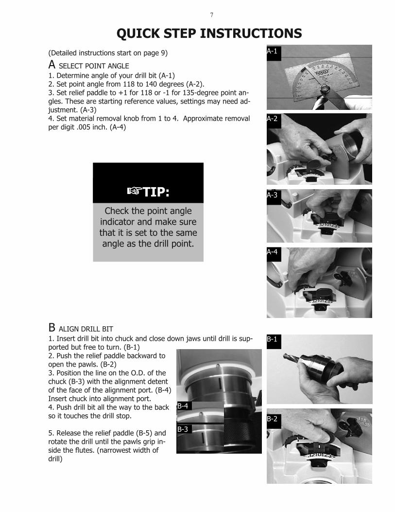
A SELECT POINT ANGLE 1. Determine angle of your drill bit (A-1) 2. Set point angle from 118 to 140 degrees (A-2). 3. Set relief paddle to +1 for 118 or -1 for 135-degree point an-gles. These are starting reference values, settings may need ad-justment. (A-3) 4. Set material removal knob from 1 to 4. Approximate removal per digit .005 inch. (A-4)
B ALIGN DRILL BIT 1. Insert drill bit into chuck and close down jaws until drill is sup-ported but free to turn. (B-1) 2. Push the relief paddle backward to open the pawls. (B-2)3. Position the line on the O.D. of the chuck (B-3) with the alignment detent of the face of the alignment port. (B-4) Insert chuck into alignment port. 4. Push drill bit all the way to the back so it touches the drill stop.
5. Release the relief paddle (B-5) and rotate the drill until the pawls grip in-side the flutes. (narrowest width of drill)
☞TIP:Check the point angle
indicator and make sure that it is set to the same angle as the drill point.
QUICK STEP INSTRUCTIONS A-1
A-2
A-3
A-4
B-1
B-2B-3
B-4
8
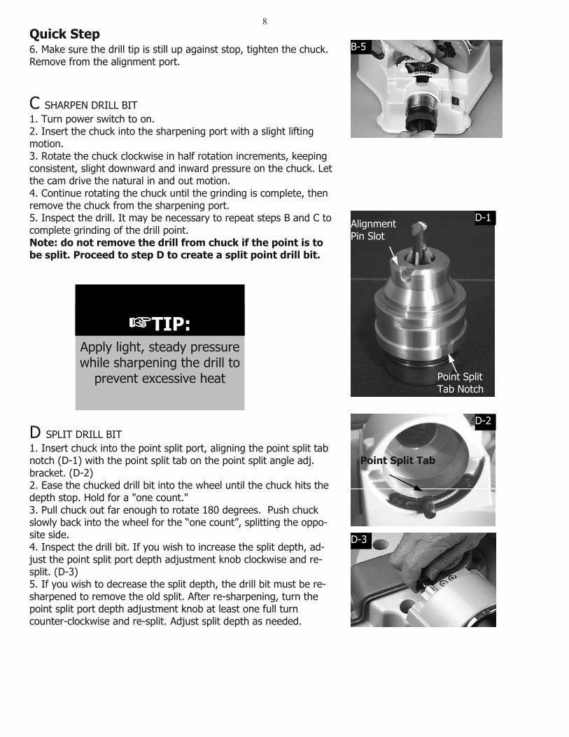
6. Make sure the drill tip is still up against stop, tighten the chuck. Remove from the alignment port.
C SHARPEN DRILL BIT 1. Turn power switch to on. 2. Insert the chuck into the sharpening port with a slight lifting motion.3. Rotate the chuck clockwise in half rotation increments, keeping consistent, slight downward and inward pressure on the chuck. Let the cam drive the natural in and out motion. 4. Continue rotating the chuck until the grinding is complete, then remove the chuck from the sharpening port. 5. Inspect the drill. It may be necessary to repeat steps B and C to complete grinding of the drill point. Note: do not remove the drill from chuck if the point is to be split. Proceed to step D to create a split point drill bit.
D SPLIT DRILL BIT 1. Insert chuck into the point split port, aligning the point split tab notch (D-1) with the point split tab on the point split angle adj. bracket. (D-2)2. Ease the chucked drill bit into the wheel until the chuck hits the depth stop. Hold for a "one count." 3. Pull chuck out far enough to rotate 180 degrees. Push chuck slowly back into the wheel for the “one count”, splitting the oppo-site side. 4. Inspect the drill bit. If you wish to increase the split depth, ad-just the point split port depth adjustment knob clockwise and re-split. (D-3) 5. If you wish to decrease the split depth, the drill bit must be re-sharpened to remove the old split. After re-sharpening, turn the point split port depth adjustment knob at least one full turn counter-clockwise and re-split. Adjust split depth as needed.
☞TIP:Apply light, steady pressure while sharpening the drill to
prevent excessive heat
Quick Step B-5
Point Split Tab
Point Split Tab Notch
AlignmentPin Slot
D-1
D-2
D-3
9
STEP 1: Drill angle identification and sharpener set up
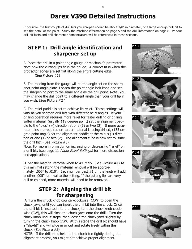
A. Place the drill in a point angle gauge or mechanic’s protractor. Note how the cutting lips fit in the gauge. A correct fit is when the protractor edges are set flat along the entire cutting edge. (See Picture #1)
B. The reading from the gauge will be the angle set on the sharp-ener point angle plate. Loosen the point angle lock knob and set the sharpening port to the same angle as the drill point. Note: You may change the drill point to a different angle than your drill tip if you wish. (See Picture #2 )
C. The relief paddle is set to achieve lip relief. These settings will vary as you sharpen drill bits with different helix angles. If your drilling operation requires more relief for faster drilling or drilling softer material, (usually 118 degree point) set the alignment pad-dle to the “plus” (+) direction at one (1) or two (2). If more accu-rate holes are required or harder material is being drilled, (135 de-gree point angle) set the alignment paddle at the minus (-) direc-tion at one (1) or two (2). The alignment tube is now set to “time the drill bit”. (See Picture #3)Note: For more information on increasing or decreasing “relief” on a drill bit, (see page 11 About Relief Settings) for more discussion and applications.
D. Set the material removal knob to #1 mark. (See Picture #4) At this minimal setting the material removal will be approxi-mately .005” to .010”. Each number past #1 on the knob will add another .005” removal to the setting. If the cutting lips are very dull or chipped, more material will need to be removed.
STEP 2: Aligning the drill bit for sharpening
A. Turn the chuck knob counter-clockwise (CCW) to open the chuck jaws, until you can insert the drill bit into the chuck. Once the drill bit is inserted into the chuck, turn the chuck knob clock-wise (CW), this will close the chuck jaws onto the drill. Turn the chuck knob until it stops, then loosen the chuck jaws slightly by turning the chuck knob CCW. At this stage the drill bit should have a “slip-fit” and will slide in or out and rotate freely within the chuck. (See Picture #5) NOTE: If the drill bit is held in the chuck too tightly during the alignment process, you might not achieve proper alignment.
Darex V390 Detailed Instructions If possible, the first couple of drill bits you sharpen should be about 3/8” in diameter, or a large enough drill bit to see the detail of the point. Study the machine information on page 5 and the drill information on page 6. Various drill bit facts and drill sharpener nomenclature will be referenced in these sections.
Pic 1
Pic 2
Pic 3
Pic 4
Pic 5
10
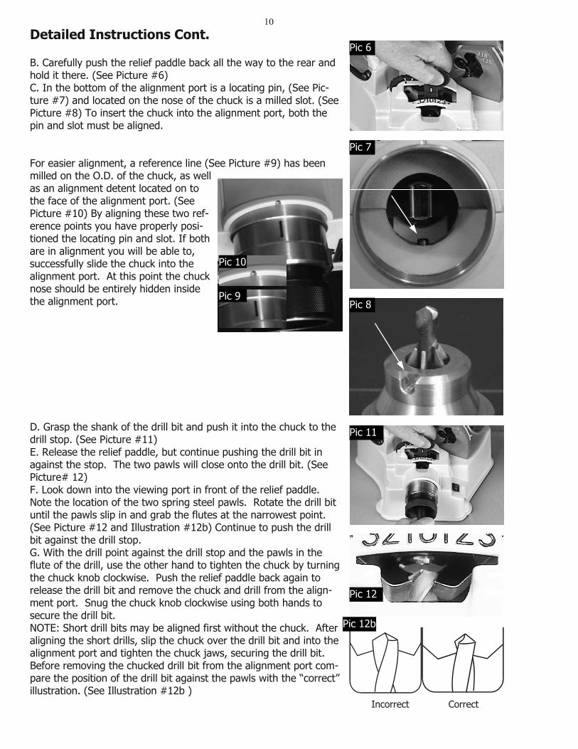
B. Carefully push the relief paddle back all the way to the rear and hold it there. (See Picture #6) C. In the bottom of the alignment port is a locating pin, (See Pic-ture #7) and located on the nose of the chuck is a milled slot. (See Picture #8) To insert the chuck into the alignment port, both the pin and slot must be aligned.
For easier alignment, a reference line (See Picture #9) has been milled on the O.D. of the chuck, as well as an alignment detent located on to the face of the alignment port. (See Picture #10) By aligning these two ref-erence points you have properly posi-tioned the locating pin and slot. If both are in alignment you will be able to, successfully slide the chuck into the alignment port. At this point the chuck nose should be entirely hidden inside the alignment port.
D. Grasp the shank of the drill bit and push it into the chuck to the drill stop. (See Picture #11)E. Release the relief paddle, but continue pushing the drill bit in against the stop. The two pawls will close onto the drill bit. (SeePicture# 12)F. Look down into the viewing port in front of the relief paddle. Note the location of the two spring steel pawls. Rotate the drill bit until the pawls slip in and grab the flutes at the narrowest point. (See Picture #12 and Illustration #12b) Continue to push the drill bit against the drill stop. G. With the drill point against the drill stop and the pawls in the flute of the drill, use the other hand to tighten the chuck by turning the chuck knob clockwise. Push the relief paddle back again to release the drill bit and remove the chuck and drill from the align-ment port. Snug the chuck knob clockwise using both hands to secure the drill bit. NOTE: Short drill bits may be aligned first without the chuck. After aligning the short drills, slip the chuck over the drill bit and into the alignment port and tighten the chuck jaws, securing the drill bit.Before removing the chucked drill bit from the alignment port com-pare the position of the drill bit against the pawls with the “correct” illustration. (See Illustration #12b )
Detailed Instructions Cont.
Incorrect Correct
Pic 6
Pic 7
Pic 8 Pic 9
Pic 10
Pic 11
Pic 12
Pic 12b
11
STEP 3: Sharpening the drill point
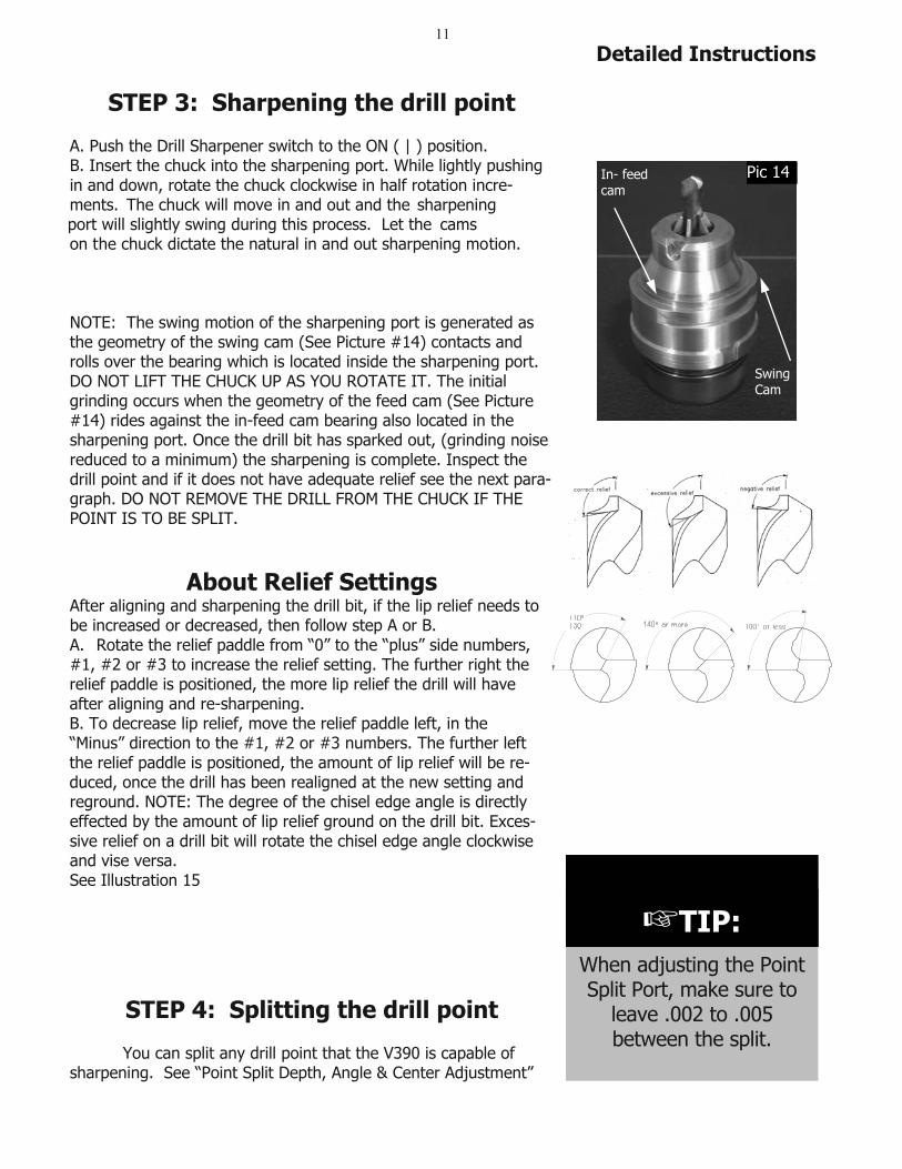
A. Push the Drill Sharpener switch to the ON ( | ) position. B. Insert the chuck into the sharpening port. While lightly pushing in and down, rotate the chuck clockwise in half rotation incre-ments. The chuck will move in and out and the sharpening
port will slightly swing during this process. Let the on the chuck dictate the natural in and out sharpening motion.
NOTE: The swing motion of the sharpening port is generated as the geometry of the swing cam (See Picture #14) contacts and rolls over the bearing which is located inside the sharpening port. DO NOT LIFT THE CHUCK UP AS YOU ROTATE IT. The initial grinding occurs when the geometry of the feed cam (See Picture #14) rides against the in-feed cam bearing also located in the sharpening port. Once the drill bit has sparked out, (grinding noise reduced to a minimum) the sharpening is complete. Inspect the drill point and if it does not have adequate relief see the next para-graph. DO NOT REMOVE THE DRILL FROM THE CHUCK IF THE POINT IS TO BE SPLIT.
About Relief Settings After aligning and sharpening the drill bit, if the lip relief needs to be increased or decreased, then follow step A or B.A. Rotate the relief paddle from “0” to the “plus” side numbers, #1, #2 or #3 to increase the relief setting. The further right the relief paddle is positioned, the more lip relief the drill will have after aligning and re-sharpening. B. To decrease lip relief, move the relief paddle left, in the “Minus” direction to the #1, #2 or #3 numbers. The further left the relief paddle is positioned, the amount of lip relief will be re-duced, once the drill has been realigned at the new setting and reground. NOTE: The degree of the chisel edge angle is directly effected by the amount of lip relief ground on the drill bit. Exces-sive relief on a drill bit will rotate the chisel edge angle clockwise and vise versa. See Illustration 15
STEP 4: Splitting the drill point
You can split any drill point that the V390 is capable of sharpening. See “Point Split Depth, Angle & Center Adjustment”
Detailed Instructions
TIP:
Swing Cam
In- feed cam
Pic 14
Ill 15
TIP:When adjusting the PointSplit Port, make sure to
leave .002 to .005between the split.
cams
12
diagrams (page 12 & 13) to help you understand split point drill bit geometry.
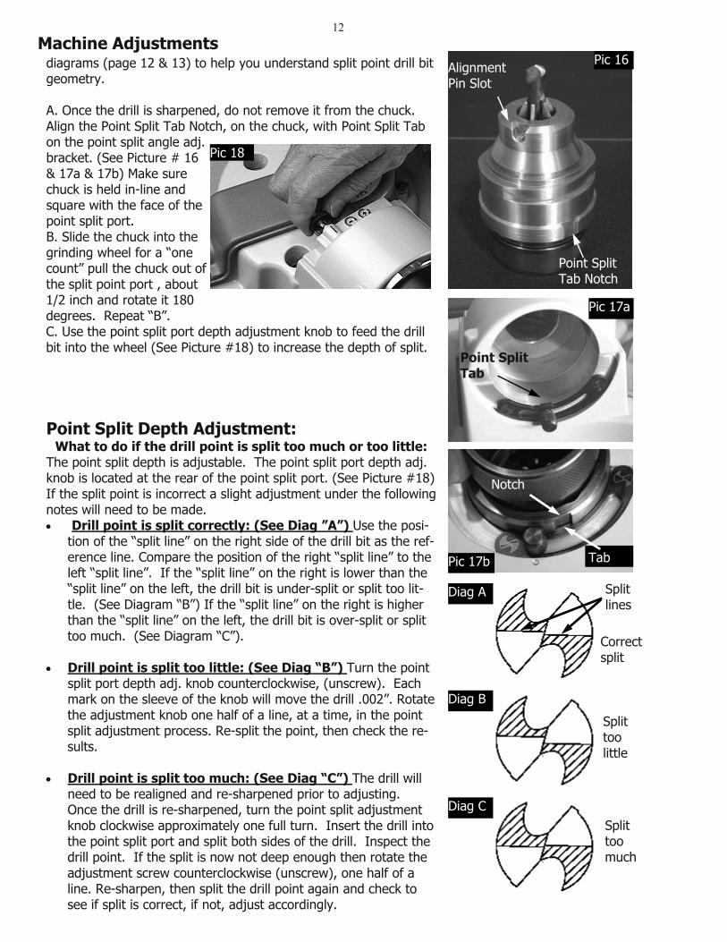
A. Once the drill is sharpened, do not remove it from the chuck. Align the Point Split Tab Notch, on the chuck, with Point Split Tab on the point split angle adj. bracket. (See Picture # 16 & 17a & 17b) Make sure chuck is held in-line and square with the face of the point split port. B. Slide the chuck into the grinding wheel for a “one count” pull the chuck out of the split point port , about 1/2 inch and rotate it 180 degrees. Repeat “B”. C. Use the point split port depth adjustment knob to feed the drill bit into the wheel (See Picture #18) to increase the depth of split.
Point Split Depth Adjustment: What to do if the drill point is split too much or too little:
The point split depth is adjustable. The point split port depth adj.knob is located at the rear of the point split port. (See Picture #18) If the split point is incorrect a slight adjustment under the following notes will need to be made.
Drill point is split correctly: (See Diag ”A”) Use the posi-tion of the “split line” on the right side of the drill bit as the ref-erence line. Compare the position of the right “split line” to the left “split line”. If the “split line” on the right is lower than the “split line” on the left, the drill bit is under-split or split too lit-tle. (See Diagram “B”) If the “split line” on the right is higher than the “split line” on the left, the drill bit is over-split or split too much. (See Diagram “C”).
Drill point is split too little: (See Diag “B”) Turn the point split port depth adj. knob counterclockwise, (unscrew). Each mark on the sleeve of the knob will move the drill .002”. Rotate the adjustment knob one half of a line, at a time, in the point split adjustment process. Re-split the point, then check the re-sults.
Drill point is split too much: (See Diag “C”) The drill will need to be realigned and re-sharpened prior to adjusting. Once the drill is re-sharpened, turn the point split adjustment knob clockwise approximately one full turn. Insert the drill into the point split port and split both sides of the drill. Inspect the drill point. If the split is now not deep enough then rotate the adjustment screw counterclockwise (unscrew), one half of a line. Re-sharpen, then split the drill point again and check to see if split is correct, if not, adjust accordingly.
Machine Adjustments
Point Split Tab Notch
AlignmentPin Slot
Pic 16
Point Split Tab
Pic 17a
Pic 18
Diag A
Diag B
Diag C
Splittoolittle
Splittoomuch
Splitlines
Correctsplit
Notch
TabPic 17b
13
Wheel too high Correct Wheel too low
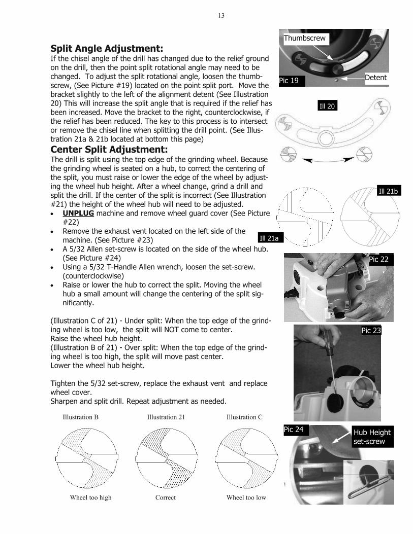
Split Angle Adjustment:If the chisel angle of the drill has changed due to the relief ground on the drill, then the point split rotational angle may need to be changed. To adjust the split rotational angle, loosen the thumb-screw, (See Picture #19) located on the point split port. Move the bracket slightly to the left of the alignment detent (See Illustration 20) This will increase the split angle that is required if the relief has been increased. Move the bracket to the right, counterclockwise, if the relief has been reduced. The key to this process is to intersect or remove the chisel line when splitting the drill point. (See Illus-tration 21a & 21b located at bottom this page)Center Split Adjustment:The drill is split using the top edge of the grinding wheel. Because the grinding wheel is seated on a hub, to correct the centering of the split, you must raise or lower the edge of the wheel by adjust-ing the wheel hub height. After a wheel change, grind a drill and split the drill. If the center of the split is incorrect (See Illustration #21) the height of the wheel hub will need to be adjusted.
UNPLUG machine and remove wheel guard cover (See Picture #22)Remove the exhaust vent located on the left side of the machine. (See Picture #23) A 5/32 Allen set-screw is located on the side of the wheel hub. (See Picture #24) Using a 5/32 T-Handle Allen wrench, loosen the set-screw. (counterclockwise) Raise or lower the hub to correct the split. Moving the wheel hub a small amount will change the centering of the split sig-nificantly.
(Illustration C of 21) - Under split: When the top edge of the grind-ing wheel is too low, the split will NOT come to center. Raise the wheel hub height. (Illustration B of 21) - Over split: When the top edge of the grind-ing wheel is too high, the split will move past center. Lower the wheel hub height.
Tighten the 5/32 set-screw, replace the exhaust vent and replace wheel cover. Sharpen and split drill. Repeat adjustment as needed.
Thumbscrew
DetentPic 19
Ill 21a Ill 21b
Pic 23
Pic 22
Hub Height set-screw
Pic 24
Illustration B Illustration C Illustration 21
Ill 20
Ill 21b
Ill 21a
14
Troubleshooting
Q: I aligned the drill bit and sharpened it, but no material gets re-moved, why ? A: You may have allowed the paddle to knock the drill bit back into the chuck. Carefully realign the drill bit in the alignment port again. Making sure the drill bit is pushed all the way against the drill stop. A: You may not have tightened the chuck tight enough to hold the drill bit in place. When the drill bit hit the wheel it was pushed back into the chuck. Realign the drill bit again using more force to tighten the jaws on to the drill bit. A: When changing point angles it may be required to advance the Material Removal Knob to a higher number. Realign drill bit at new Material Removal Setting. Q: I'm getting negative relief! Negative relief is present when the heel behind the cutting lip is higher than the cutting lip on the drill bit. When negative relief occurs the drill bit will not cut. A: To correct this problem, move the paddle toward the right, try number 2 or 3 for an increased relief setting. Realign the drill bit and re-sharpen. A: Maintain consistent inward pressure on the chuck during the sharpening process. Make sure grinding is completed and the drill bit has been sparked out. (Grinding noise reduced to a minimum) A: The Material Removal Knob may be set to remove too much material. Reduce amount of material being removed from the end of the drill bit by setting the Material Removal Knob to a lesser number. Realign drill bit and sharpen. Q: Why is the drill point off center? If the tip of the drill bit ap-pears to be sharpened off center, check the following items: A: Make sure that there are no particles between the chuck jaws and the drill bit, which could hold it off center. A: Make sure the closing knob is tightened firmly enough to hold the drill bit on center. A: During the sharpening process be sure not to push unevenly while rotating the chuck. A: The drill may be bent. Roll it on a flat surface to check for straightness. A: Spark out the drill bit. Q: Why don’t my drills align correctly, like the "correct" diagram? A: There may be a burr on the drill shank (remove burrs with a flat file). A: The drill may be too loose or too tight in chuck. Q: What can I do about the flat spot between the lip and the heel?A: The flat spots or chattering on a sharpened drill, is the result of an incomplete or irregular rotation of the chuck in the sharpening port. To correct, apply firm, not excessive inward pressure and rotate the chuck smoothly while sharpening. Do not lift up on the chuck while rotating it. Be sure to complete the grind.
☞TIP:If the chisel angle on the tip is too far clockwise, realign
the drill with a reduced relief setting.
☞TIP:Clean CBN and diamond wheels with an oil-less solvent, for example,
automotive brake cleaner.
☞TIP:Sparking out drill bits while sharpening improves drill
point concentricity.
☞TIP:Darex manufactures other
sharpeners capable of creating a variety of
specialty points.
15
☞TIP:Periodically clean the
grindings from inside the chuck to make sure it will
maintain accuracy.
☞TIP:To sharpen very small drills, set the material
removal at the smallest (#1) amount of material.
☞TIP:While aligning the drill,
make sure that the spring steel pawls are fully inside
the flutes of the drill.
Q: The chisel edge on my drill bit is too long and flat! A: During the alignment process the pawls were not gripping "ON" the flutes of the drill bit. Re-align the drill bit making sure that the pawls are centered in the flutes. A: Too much heel relief. Realign drill bit toward the minus setting and re-sharpen. Q: After sharpening, the grind finish on my drill is rough! A: Grind finish is initially rough when sharpened on a new wheel. Drill performance will not be noticeably affected. However, the fin-ish will improve as the crystal surfaces wear evenly. A: Rotating the chuck too fast in the sharpening process can cre-ate a rough finish. Q: Why is my point split uneven? Pictures on page 7, "Point Splitter Adjustments" show drill points that are split, "Too little", "Too much", and a drill point that is "Correctly split". A: To correct an uneven point split, take more material off of the under split flute. To do this, reinsert the chuck in the splitting tube with the under split side down. Repeat procedure on page 7 - Step B, to correct the split. A correct split point should look symmetri-cal. The two parallel lines formed by the split should have a sepa-ration of .002" to .005" on the chisel angle. Q: Can I sharpen left-hand drill bits? A: Not with this unit. However, Darex Industrial does offer other precision drill bit sharpeners that will sharpen left-hand drill bits. They can be reached at 1-800-547-0222 or online at http://www.darex.com Q: Motor stops running, won't restart!The motor will shut off when the following occurs: A: The wheel is jammed and the motor is stalled. Push the On/Off switch to "OFF" and unplug the electrical cord. Remove the wheel cover and check to see if the wheel rotates freely. Make sure that all grindings are cleaned out and no obstructions are in the wheel cavity area. Once this is done and the wheel turns freely, plug the machine back in to the electrical receptacle and follow the restart-ing procedures. A: The machine is tipped at an angle or is turned over. A: An extreme voltage change occurs to the motor. A: Too heavy of use for an extended time, the motor overheats. A: If the motor is short-circuited for any reason. When the motor shuts off from any of the above reasons, reset the on/off switch to “ON”. The motor should restart. If motor does not start allow the unit to cool down for approximately 30 minutes. Then push the “ON” switch again. NOTICE: The V390 Drill Sharpener is equipped with multiple safety features which turn the motor off when certain occurrences happen to the machine. For example, turning the machine on its side will cause the circuit breaker to trip. Machine must be placed upright.If the unit won't start by following the above procedures call Darex Corporation at 1-800-547-0222 and ask for Technical Service.
Troubleshooting
16
DAREX V390 MAINTENANCE
Cleaning the DAREX V390 Unplug the Drill Bit Sharpener. Using a dry paintbrush or a cloth, clean the inside and outside of the Alignment, Sharpening and Splitting ports to remove any grindings that may have accumu-lated. (See Picture #25) The attachment of a vacuum with a stan-dard vacuum hose works well to keep the grit area clean. (See “Vacuum Tube” below) Removing the wheel cover Unplug the Drill Bit Sharpener. Using a 3mm hex wrench, remove the three hex head screws holding the wheel cover on. (See Pic-ture #26) Lift the wheel cover off and with a dry brush remove any grinding dust. (See Picture #27) Determining if a wheel change is required 1. Sharpened drill bits will burn or turn blue no matter how fast or slow you rotate the chuck. 2. Upon inspecting the wheel, it appears smooth as if there is no abrasive. (See “Cleaning the electroplated CBN or diamond wheel” ) 3. When sharpening a drill bit, if it takes an extreme number of rotations to sharpen the tool, then the wheel will need to be re-placed. Contact the company or distributor where the sharpener was purchased for replacement wheels. Removing the wheel MAKE SURE THE UNIT IS UNPLUGGED! Once wheel cover is re-moved, insert a Phillips head screwdriver into the wheel retainer bolt on the top of the wheel and turn it counterclockwise to loosen. (See Picture #28) Using a hex wrench remove the bolt and wheel retainer. Lift the wheel off of the motor hub. (See Picture #29) Remove dust particles from the wheel hub and grinding wheel area with a small dry brush. Dispose of drill grinding dust in a safe and environmentally approved manner. Prior to re-installing the wheel make sure to clean all grindings off of hub and wheel. Replacing the wheel To re-install wheel, reverse steps taken to remove wheel.
Cleaning the chuck Using pressurized air, blow grindings out of the chuck from the knob end. For further cleaning, disassemble the chuck by merely unscrewing the closing knob on the chuck and removing the chuck body. Clean the inside of the chuck with a dry paintbrush. Do not remove the springs and jaws from the holder! Once the inside of the chuck has been cleaned, apply a drop or so of light lube on the threads. Slide the chuck body onto the jaws, rotate the closing knob clockwise to reassemble the chuck. (See Picture #30)
Pic 25
Pic 26
Pic 27
Pic 28
Pic 29
Pic 30
17Maintenance
Vacuum tube PP11230TF) If a vacuum system is available it is strongly recommended to at-tach the air vacuum tube to the exhaust of the sharpening port. To attach the tube: Unplug the machine. Remove the wheel cover screws and remove the vacuum port plug. (See Picture #31) In-sert the vacuum tube into the groove in the port. (See Picture #32) Re-install the screws that hold the wheel cover down. Attach a vacuum source to the 1-1/4" diameter tube.
Cleaning the electroplated CBN or diamond wheel These wheels are maintenance free. No truing or dressing is re-quired on these type of wheels. However, wheels should be cleaned on a routine basis. After removing the wheel from the unit, saturate with any type of oil-less solvent, such as Automotive Brake Cleaner. If you wish to, you can use a soft bristle brush and lightly brush the wheel after saturation, re-saturate the wheel to remove any debris that was loosened. NOTE: If the wheel performs as though it needs changing, it may just need cleaning.
Changing the light bulbUnplug machine Lay machine on it side (See Picture #33) Remove screws and the bottom cover plate (See Picture #34) The 10 watt bulb is held in a bayonet lamp receptacle. See Picture #35)To remove push in and twist bulb counter-clockwise. (See Picture #36) Remove bulb.
To replace the bulb. Align the tang on the bulb with slot on recep-tacle. Push to the back and turn clockwise.
(2)SA02184EA - 115-125 volt 10 Watt Bulb (1)PP02185EF - 230-volt 10 Watt Bulb (International units) (1)SA02186EA - Bayonet Lamp Receptacle (115v & 230v)
Pic 31
Pic 32
Pic 33
Pic 34
Pic 35
Pic 36
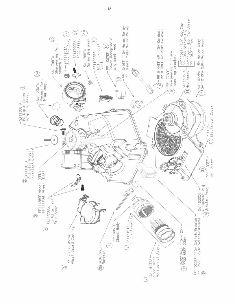
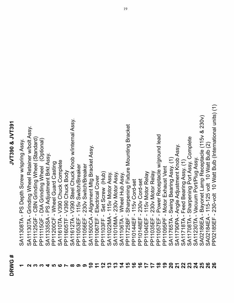
18
19D
RW
G #
JV
T390
& J
VT39
1
1S
A11
308T
A - P
S D
epth
Scr
ew w
/spr
ing
Ass
y.
2S
A11
130T
A - G
rindi
ng W
heel
Ret
aine
r w/b
olt A
ssy.
3
PP
1112
5GF
- CB
N G
rindi
ng W
heel
(Sta
ndar
d)
3PP
1111
5GF
- DIA
Grin
ding
Whe
el
(Opt
iona
l)4
SA
1133
5SA
- PS
Adj
ustm
ent B
rkt A
ssy.
5
PP
1120
0CF
- Whe
el G
uard
Cas
ting
6S
A11
610T
A - V
390
Chu
ck C
ompl
ete
7P
P11
605T
F - V
390
Chu
ck B
ody
8S
A11
612T
A - V
390
Stee
l Chu
ck K
nob
w/in
tern
al A
ssy.
9
PP
1105
3EF
- 115
v S
witc
h/B
reak
er
9P
P11
056E
F - 2
30v
Sw
itch/
Bre
aker
10S
A11
500C
A - A
lignm
ent M
tg B
rack
et A
ssy.
11
P
P11
067E
F - E
lect
rical
Cov
er
12P
P11
103F
F -
Set
Scr
ew (
Hub
) 13
SA
1102
2MA
- 115
v M
otor
Ass
y.
13S
A11
010M
A - 2
30v
Mot
or A
ssy.
14S
A11
106T
A -
Whe
el H
ub A
ssy.
15
PP
1172
5BF
- Sha
rpen
ing
Fixt
ure
Mou
ntin
g B
rack
et
16P
P10
144E
F - 1
15v
Cor
d-se
t 16
PP
1014
8EF
- 230
v C
ord-
set
17P
P11
040E
F - 1
15v
Mot
or R
elay
17
PP
1103
5EF
- 230
v M
otor
Rel
ay18
PP
1105
7EF
- Pow
er R
ecep
tacl
e w
/gro
und
lead
19
PP
1109
5PF
- Mot
or E
xhau
st V
ent
20S
A11
765T
A - S
win
g B
earin
g A
ssy.
(1)
21S
A11
790P
A - A
ngle
Adj
ustm
ent K
nob
Ass
y.
22S
A11
718T
A - F
eed
Bea
ring
Ass
y. (1
) 23
SA
1170
8TA
- Sha
rpen
ing
Por
t Ass
y. C
ompl
ete
24S
A11
230T
A - V
acuu
m P
ort/P
lug
Ass
y.
25S
A02
186E
A - B
ayon
et L
amp
Rec
epta
cle
(115
v &
230
v)
26S
A02
184E
A - 1
15-1
25 v
olt
10 W
att B
ulb
(2)
26P
P02
185E
F - 2
30-v
olt
10 W
att B
ulb
(Inte
rnat
iona
l uni
ts) (
1)
PP11852KF - Rev 3
WORLD’S BEST SELLING INDUSTRIAL DRILL SHARPENERS
Phone:800-547-0222541-488-2224
DarexP O Box 730
210 E Hersey StAshland, OR 97520
USA
Fax:541-488-2229
Email:[email protected]
Web:www.darex.com