Embed Size (px)
Citation preview
Technical Information for Drills Indexable DrillsIndex Drills
Available Insert
Technical Information for KING DRILL
KING DRILL
Technical Information for TPDB
Available Insert for TPDB
TPDB
Technical Information for WPDC
Center Drill
WPDC
G02G04
G06G10G18G21G22G25G28G29
C O N T E N T S
GDRILL
Korloy drills provides total solutions in hole making based on development,
research and tooling know-how.
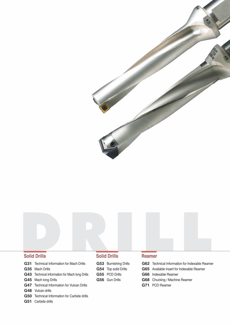
DRILLSolid DrillsSolid Drills Reamer
Burnishing Drills
Top solid Drills
PCD Drills
Gun Drills
Technical Information for Mach Drills
Mach Drills
Technical Information for Mach long Drills
Mach long Drills
Technical Information for Vulcan Drills
Vulcan drills
Technical Information for Carbide drills
Carbide drills
Technical Information for Indexable Reamer
Available Insert for Indexable Reamer
Indexable Reamer
Chucking / Machine Reamer
PCD Reamer
G53G54G55G56
G31G35G43G45G47G48G50G51
G62G65G66G68G71
Dri
lls
2
G
GIn
dex
Dril
ls
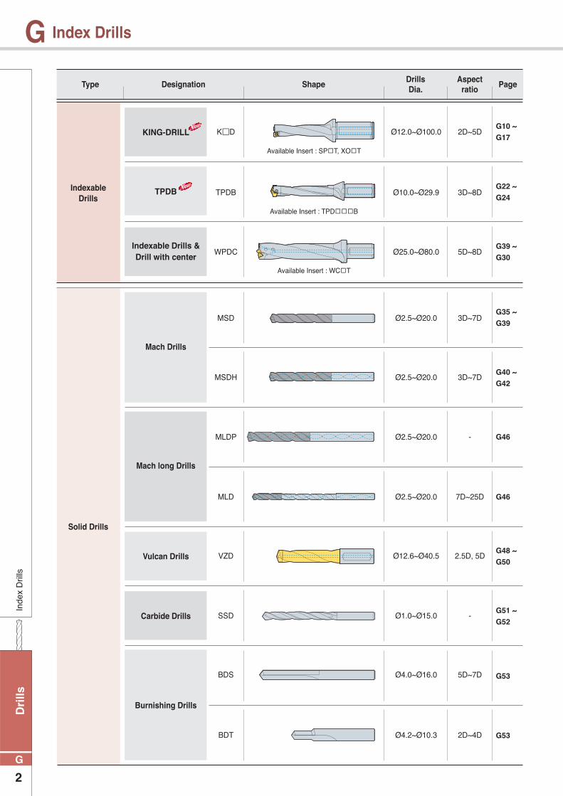
Index Drills
IndexableDrills
Solid Drills
K D
TPDB
WPDC
MSD
MSDH
MLDP
MLD
VZD
SSD
BDS
BDT
Ø12.0~Ø100.0
Available Insert : SP▫T, XO▫T
Available Insert : TPD▫▫▫B
Available Insert : WC▫T
Ø10.0~Ø29.9
Ø25.0~Ø80.0
Ø2.5~Ø20.0
Ø2.5~Ø20.0
Ø2.5~Ø20.0
Ø2.5~Ø20.0
Ø12.6~Ø40.5
Ø1.0~Ø15.0
Ø4.0~Ø16.0
Ø4.2~Ø10.3
2D~5D
3D~8D
5D~8D
3D~7D
3D~7D
-
7D~25D
2.5D, 5D
-
5D~7D
2D~4D
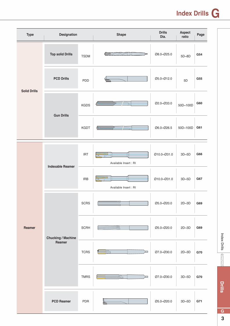
Type Designation ShapeDrills Dia.
Aspect ratio
Page
G10 ~
G17
G22 ~
G24
G39 ~
G30
G35 ~
G39
G40 ~
G42
G46
G46
G48 ~
G50
G51 ~
G52
G53
G53
KING-DRILL
TPDB
Vulcan Drills
Carbide Drills
Mach Drills
Mach long Drills
Burnishing Drills
Indexable Drills & Drill with center
Drills
3
G
GIndex D
rills
Index Drills
Solid Drills
Reamer
TSDM
PDD
PDR
KGDS
IRT
IRB
SCRS
SCRH
TCRS
TMRS
KGDT
Ø8.0~Ø25.0
Ø5.0~Ø12.0
Ø5.0~Ø20.0
Ø2.0~Ø33.0
Ø10.0~Ø31.0
Ø10.0~Ø31.0
Ø5.0~Ø20.0
Ø5.0~Ø20.0
Ø7.0~Ø30.0
Ø7.0~Ø30.0
Ø6.0~Ø26.5
Available Insert : RI
Available Insert : RI
5D~8D
5D
3D~5D
50D~100D
3D~5D
3D~5D
2D~3D
2D~3D
2D~3D
3D~5D
50D~100D
Type Designation ShapeDrills Dia.
Aspect ratio
Page
G70
G67
G66
G61
G60
G55
G54
G70
G69
G71
G69
Top solid Drills
PCD Drills
PCD Reamer
Gun Drills
Indexable Reamer
Chucking / Machine Reamer
Dri
lls
4
G
GA
vaila
ble
Inse
rt
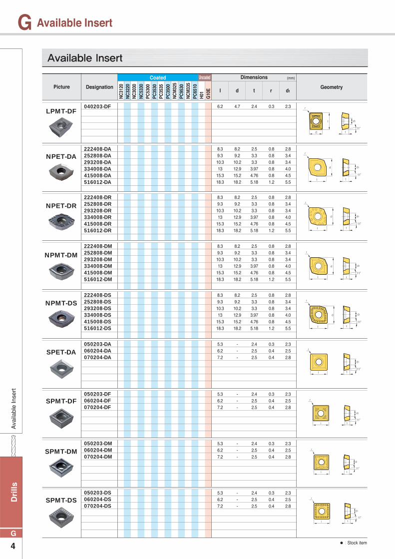
Available Insert
LPMT-DF
NPET-DA
NPET-DR
NPMT-DM
NPMT-DS
SPET-DA
SPMT-DF
SPMT-DM
SPMT-DS
040203-DF
222408-DA252808-DA293208-DA334008-DA415008-DA516012-DA
222408-DR252808-DR293208-DR334008-DR415008-DR516012-DR
222408-DM252808-DM293208-DM334008-DM415008-DM516012-DM
222408-DS252808-DS293208-DS334008-DS415008-DS516012-DS
050203-DA060204-DA070204-DA
050203-DF060204-DF070204-DF
050203-DM060204-DM070204-DM
050203-DS060204-DS070204-DS
6.2 4.7 2.4 0.3 2.3
8.39.310.313
15.318.3
8.29.210.212.915.218.2
2.53.33.33.974.765.18
0.80.80.80.80.81.2
2.83.43.44.04.55.5
8.39.310.313
15.318.3
8.29.210.212.915.218.2
2.53.33.33.974.765.18
0.80.80.80.80.81.2
2.83.43.44.04.55.5
8.39.310.313
15.318.3
8.29.210.212.915.218.2
2.53.33.33.974.765.18
0.80.80.80.80.81.2
2.83.43.44.04.55.5
8.39.310.313
15.318.3
8.29.210.212.915.218.2
2.53.33.33.974.765.18
0.80.80.80.80.81.2
2.83.43.44.04.55.5
5.36.27.2
---
2.42.52.5
0.30.40.4
2.32.52.8
5.36.27.2
---
2.42.52.5
0.30.40.4
2.32.52.8
5.36.27.2
---
2.42.52.5
0.30.40.4
2.32.52.8
5.36.27.2
---
2.42.52.5
0.30.40.4
2.32.52.8
Picture Designation
Dimensions (mm)
I d1d t r
Coated Uncoated
Geometry
NC32
20NC
3120
PC35
30
NCM
335
PC65
10
NC53
30
PC35
00
H01
NC30
30
PC35
35
PC53
00
PC95
30NC
M32
5
G10
E
Available Insert
● : Stock item
Drills
5
G
GA
vailable Insert
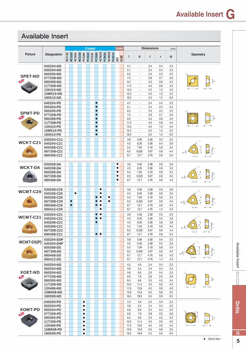
Available Insert
●●●●●
●●●●●●●●●
●●
●●●
●●
●●●●●●●
●●●
●
●●
●
SPET-ND
SPMT-PD
XOET-ND
XOMT-PD
WCKT-C21
WCKT-DA
WCMT-C20
WCMT-C21
WCMT-DS(P)
040204-ND050204-ND060205-ND07T208-ND090308-ND11T308-ND130410-ND15M510-ND180510-ND
040204-PD050204-PD060205-PD07T208-PD090308-PD11T308-PD130410-PD15M510-PD180510-PD
040204-ND050204-ND060204-ND07T205-ND090305-ND11T306-ND130406-ND15M508-ND180508-ND
040204-PD050204-PD060204-PD07T205-PD090305-PD11T306-PD130406-PD15M508-PD180508-PD
030204-C21040204-C21050308-C2106T308-C21080408-C21
030208-DA040208-DA050308-DA06T308-DA080408-DA
030208-C20040208-C20050308-C2006T308-C20080408-C20080412-C20
030204-C21040204-C21040208-C21050308-C2106T308-C21080408-C21
030204-DSP040204-DSP050308-DS06T308-DS080408-DS080412-DS
4.75.16.27.59.211.013.015.218.2
4.75.16.27.59.211.013.015.218.2
---------
---------
2.42.42.52.83.34.04.55.05.5
2.42.42.52.83.34.04.55.05.5
0.40.40.50.70.80.81.01.01.0
0.40.40.50.70.80.81.01.01.0
2.32.32.52.83.44.04.55.56.0
2.32.32.52.83.44.04.55.56.0
4.34.85.86.98.410.011.913.916.5
4.34.85.86.98.410.011.913.916.5
4.95.46.67.89.611.413.615.918.9
4.95.46.67.89.611.413.615.918.9
2.42.42.52.83.34.04.55.05.5
2.42.42.52.83.34.04.55.05.5
0.40.40.40.50.50.60.60.80.8
0.40.40.40.50.50.60.60.80.8
2.32.32.52.83.44.04.55.56.0
2.32.32.52.83.44.04.55.56.0
3.84.35.46.58.7
5.566.357.949.52512.7
2.382.383.183.974.76
0.40.40.80.80.8
2.52.83.44.45.5
3.84.35.46.58.7
5.566.357.949.52512.7
2.382.383.183.974.76
0.80.80.80.80.8
2.83.03.44.04.3
3.84.35.46.58.78.7
5.566.357.949.52512.712.7
2.382.383.183.974.764.76
0.80.80.80.80.81.2
2.83.03.44.04.34.3
3.84.34.35.46.58.7
5.566.356.357.949.52512.7
2.382.382.383.183.974.76
0.40.40.80.80.80.8
2.52.82.83.44.45.5
3.84.35.46.58.78.7
5.566.357.949.52512.712.7
2.382.383.183.974.764.76
0.40.40.80.80.81.2
2.52.83.44.04.34.3
Picture Designation
Dimensions (mm)
I d1d t r
Coated Uncoated
Geometry
NC32
20NC
3120
PC35
30
NCM
335
PC65
10
NC53
30
PC35
00
H01
NC30
30
PC35
35
PC53
00
PC95
30NC
M32
5
G10
E
Available Insert
● : Stock item
●●●●●●●●●
Dri
lls
6
G
GTe
chni
cal I
nfor
mat
ion
for
Inde
xabl
e D
rills
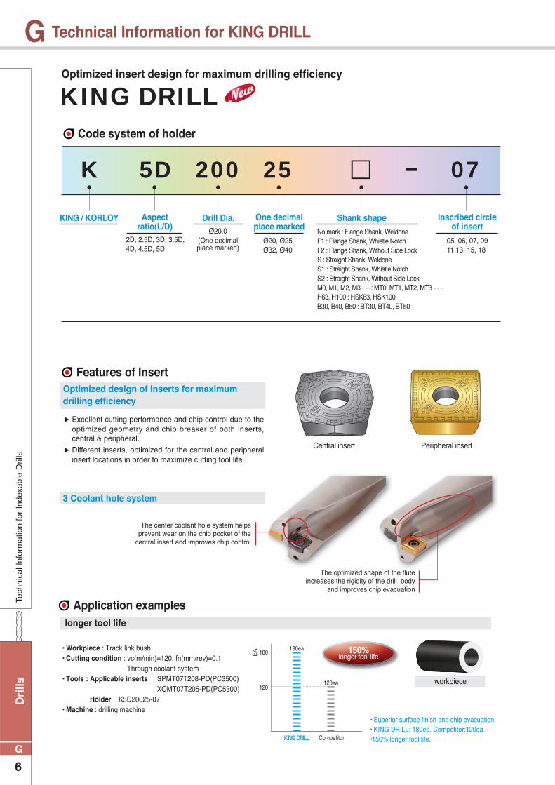
Technical Information for KING DRILL
KING / KORLOY Aspect ratio(L/D)
Drill Dia. One decimal place marked
Shank shape Inscribed circle of insert
2D, 2.5D, 3D, 3.5D, 4D, 4.5D, 5D
Ø20.0(One decimal place marked)
Ø20, Ø25Ø32, Ø40
No mark : Flange Shank, WeldoneF1 : Flange Shank, Whistle NotchF2 : Flange Shank, Without Side Lock S : Straight Shank, WeldoneS1 : Straight Shank, Whistle NotchS2 : Straight Shank, Without Side Lock M0, M1, M2, M3 - - -: MT0, MT1, MT2, MT3 - - -H63, H100 : HSK63, HSK100B30, B40, B50 : BT30, BT40, BT50
05, 06, 07, 09 11 13, 15, 18
K 5D 25 07200
Code system of holder
Application examples
Features of Insert
▶ Excellent cutting performance and chip control due to the optimized geometry and chip breaker of both inserts, central & peripheral.
▶ Different inserts, optimized for the central and peripheral insert locations in order to maximize cutting tool life.
The center coolant hole system helps prevent wear on the chip pocket of the
central insert and improves chip control
The optimized shape of the flute increases the rigidity of the drill body
and improves chip evacuation
Optimized design of inserts for maximum drilling efficiency
longer tool life
3 Coolant hole system
Central insert Peripheral insert
150% longer tool life
180ea
120ea
EA
KING DRILL Competitor
120
180
workpiece
• Superior surface finish and chip evacuation.• KING DRILL: 180ea, Competitor:120ea•150% longer tool life.
KING DRILLOptimized insert design for maximum drilling efficiency
• Workpiece : Track link bush• Cutting condition : vc(m/min)=120, fn(mm/rev)=0.1 Through coolant system • Tools : Applicable inserts SPMT07T208-PD(PC3500) XOMT07T205-PD(PC5300) Holder K5D20025-07• Machine : drilling machine
Drills
7
G
GTechnical Inform
ation for Indexable Drills
Technical Information for KING DRILL
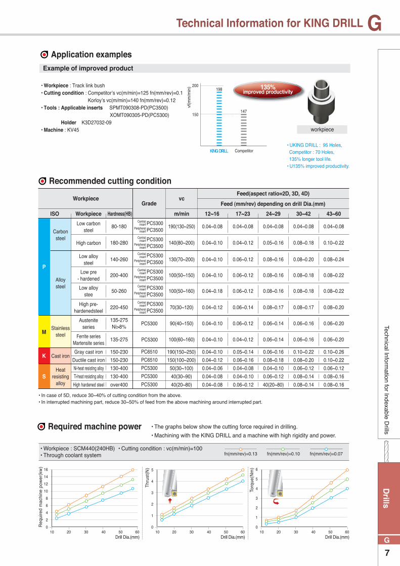
Application examples
Recommended cutting condition
• In case of 5D, reduce 30~40% of cutting condition from the above.• In interrupted machining part, reduce 30~50% of feed from the above machining around interrupted part.
Example of improved product
135% improved productivity198
147
vf(m
m/m
in)
KING DRILL Competitor
150
200
ISO
PC5300PC3500
PC5300PC3500
PC5300PC3500
PC5300PC3500
PC5300PC3500
PC5300PC3500
P
K
S
M
PC5300
PC5300
PC6510
PC5300
PC6510
PC5300
PC5300
Workpiece
Carbon steel
Alloy steel
Stainless steel
Cast iron
Heat resisting
alloy
80-180Central
insert
Central insert
Central insert
Central insert
Central insert
Central insert
Peripheral insert
Peripheral insert
Peripheral insert
Peripheral insert
Peripheral insert
Peripheral insert
180-280
140-260
200-400
50-260
220-450
135-275 Ni>8%
135-275
150-230
150-230
130-400
130-400
over400
190(130~250)
140(80~200)
130(70~200)
100(50~150)
100(50~160)
70(30~120)
90(40~150)
100(60~160)
190(150~250)
150(100~200)
50(30~100)
40(30~90)
40(20~80)
0.04~0.08
0.04~0.10
0.04~0.10
0.04~0.10
0.04~0.18
0.04~0.12
0.04~0.10
0.04~0.10
12~16
0.04~0.10
0.04~0.12
0.04~0.06
0.04~0.08
0.04~0.08
Low carbonsteel
High carbon
Low alloy steel
Low pre- hardened
Low alloy stee
High pre-hardenedsteel
Austeniteseries
Gray cast iron
Ductile cast iron
Ni-heat resisting alloy
Ti-heat resisting alloy
High hardened steel
Ferrite seriesMartensite series
0.04~0.08
0.04~0.12
0.06~0.12
0.06~0.12
0.06~0.12
0.06~0.14
0.06~0.12
0.04~0.12
0.05~0.14
0.06~0.16
0.04~0.08
0.04~0.10
0.06~0.12
17~23Hardness(HB)
0.04~0.08
0.05~0.16
0.08~0.16
0.08~0.16
0.08~0.16
0.08~0.17
0.06~0.14
0.06~0.14
0.06~0.16
0.08~0.18
0.04~0.10
0.06~0.12
40(20~80)
24~29
0.04~0.08
0.08~0.18
0.08~0.20
0.08~0.18
0.08~0.18
0.08~0.17
0.06~0.16
0.06~0.16
0.10~0.22
0.08~0.20
0.06~0.12
0.08~0.14
0.08~0.14
30~42
0.04~0.08
0.10~0.22
0.08~0.24
0.08~0.22
0.08~0.22
0.08~0.20
0.06~0.20
0.06~0.20
0.10~0.26
0.10~0.22
0.06~0.12
0.08~0.16
0.08~0.16
43~60m/min
GradeWorkpiece vc
Feed(aspect ratio=2D, 3D, 4D)
Feed (mm/rev) depending on drill Dia.(mm)
workpiece
• U KING DRILL : 95 Holes, Competitor : 70 Holes, 135% longer tool life.• U135% improved productivity.
Required machine power • The graphs below show the cutting force required in drilling.
• Machining with the KING DRILL and a machine with high rigidity and power.
Req
uire
d m
achi
ne p
ower
(kw
)
16
14
12
10
8
6
4
2
010 20 30 40 50 60
Drill Dia.(mm)
• Workpiece : SCM440(240HB) • Cutting condition : vc(m/min)=100 • Through coolant system fn(mm/rev)=0.13 fn(mm/rev)=0.10 fn(mm/rev)=0.07
5
4
3
2
1
010 20 30 40 50 60
Drill Dia.(mm)
6
5
4
3
2
1
010 20 30 40 50 60
Drill Dia.(mm)
• Workpiece : Track link bush• Cutting condition : Competitor’s vc(m/min)=125 fn(mm/rev)=0.1 Korloy’s vc(m/min)=140 fn(mm/rev)=0.12• Tools : Applicable inserts SPMT090308-PD(PC3500) XOMT090305-PD(PC5300) Holder K3D27032-09• Machine : KV45
Thr
ust(
N)
Torq
ue(N
m)

Dri
lls
8
G
GTe
chni
cal I
nfor
mat
ion
for
Inde
xabl
e D
rills
Technical Information for KING DRILL
Insert and parts
Cutting oil quantity
Notice for setting the drill in the lathe.
Drill tolerance and hole tolerance
• Set the peripheral insert parallel to the X axis. (based on the side lock)• If the machined core is 0.5mm after machining 5mm, that is the proper setting.
※ Please make sure that the location of the side lock could be different depending on manufacturers of machine.
• In clamping insert, clean the tip seat and apply the CASMOLY1000 on screw.
• Make sure to use Korloy's screw and ranch only.
• Recommended pressure of coolant : 5kg/cm2 above
• The data of the graph above could be changed depending on workpiece and cutting condition.
40
35
25
20
15
10
5
00 13 20 30 40 55
Drill Dia.(mm)
Cut
ting
oil q
uant
ity(ℓmin)
Recommended cutting oil quantity
Min. cutting oil quantity
• Workpiece : SCM440(240HB) • Cutting condition : vc(m/min)=100 • Through coolant system
(mm)
0 ~ -0.15
+0.2 ~ -0.1
0 ~ -0.15
+0.25 ~ -0.05
SPMT040204-PD
SPMT050204-PD
SPMT060205-PD
SPMT07T208-PD
SPMT090308-PD
SPMT11T308-PD
SPMT130410-PD
SPMT15M510-PD
SPMT180510-PD
XOMT040204-PD
XOMT050204-PD
XOMT060204-PD
XOMT07T205-PD
XOMT090305-PD
XOMT11T306-PD
XOMT130406-PD
XOMT15M508-PD
XOMT180508-PD
FTNA0204
FTNA0204
FTKA02206S
FTKA02565
FTKA0307
FTKA03508
FTKA0410
FTNC04511
FTNA0511
TW06S
TW06S
TW07S
TW07S
TW09S
TW15S
TW15S
TW20S
TW20S
0.4
0.4
0.8
0.8
1.2
3
3
5
5
Drill tolerance(ØD)
Hole tolerance
Drill tolerance(ØD)
Hole tolerance
Ø12.0~Ø13.5
Ø13.6~Ø16.0
Ø16.1~Ø19.5
Ø19.6~Ø23.5
Ø23.6~Ø29.5
Ø29.6~Ø35.5
Ø35.6~Ø42.5
Ø42.6~Ø50.5
Ø50.6~Ø60.5
2D~3D
4D~5D
0 ~ -0.15
+0.25 ~ -0.1
0 ~ -0.15
+0.3 ~ -0.05
0 ~ -0.15
+0.28 ~ -0.1
0 ~ -0.15
+0.33 ~ -0.05
Drill Dia.
Dia. of drill
Ø12 ~ Ø29
Peripheral insert Central insert Screw Wrench Torque(Nm)
Ø30 ~ Ø45 Ø46 ~ Ø60
1 2 3
X-axis
± 0.03mmCore diameter : 0.5mm
Drills
9
G
GTechnical Inform
ation for Indexable Drills
Technical Information for KING DRILL
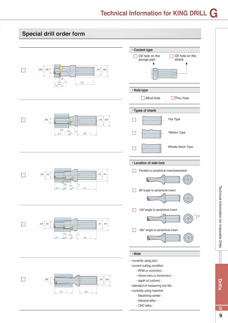
Special drill order form
• Coolant type
• Hole type
• Types of shank
Blind hole Thru hole
Oil hole on the plunge part
Oil hole on the shank
Flat Type
Weldon Type
Whistle Notch Type
• Location of side lock
90°angle to peripheral insert
150°angle to peripheral insert
180° angle to peripheral insert
Parallel to peripheral insert(standard)
• Note
• currently using tool :
• current cutting condition
- RPM or vc(m/min) :
- vf(mm.min) or fn(mm/rev) :
- depth of cut(mm) :
• standard of measuring tool life :
• currently using machine
- Machining center :
- General lathe :
- CNC lathe :

Dri
lls
10
G
G
12.012.513.013.514.014.515.015.516.016.517.017.518.018.519.019.520.020.521.021.522.022.523.023.524.024.525.025.526.026.527.027.528.028.529.029.530.030.531.031.532.032.533.033.534.034.535.035.536.036.537.037.5
20202020202020202025252525252525252525252525252532323232323232323232323232323232323232323232323240404040
25252525252525252534343434343434343434343434343444444444444444444444444444444444444444444444444448484848
27 27 29 29 31 31 33 33 35 35 37 37 39 39 41 41 43 43 45 45 47 47 49 49 51 51 53 53 55 55 57 57 59 59 61 61 63 63 65 65 67 67 69 69 71 71 73 73 76 76 78 78
50505050505050505056565656565656565656565656565660606060606060606060606060606060606060606060606070707070
91 91 93 93 96 96 99 99 101 107 109 109 112 112 114 114 118 118 120 120 122 122 126 126 133 133 135 135 137 137 140 140 143 143 145 145 150 150 152 152 154 154 157 157 159 159 161 161 176 176 178 178
SPMT040204-PD
XOMT040204-PDFTNA0204 TW06S
SPMT050204-PD
XOMT050204-PDFTNA0204 TW06S
SPMT060205-PD
XOMT060204-PDFTKA02206S TW07S
SPMT07T208-PD
XOMT07T205-PDFTKA02565 TW07S
SPMT090308-PD
XOMT090305-PDFTKA0307 TW09S
SPMT11T308-PD
XOMT11T306-PDFTKA0307 TW15S
SPMT130410-PD
XOMT130406-PDFTKA0410 TW15S
12020-0412520-0413020-0413520-0414020-0514520-0515020-0515520-0516020-0516525-0617025-0617525-0618025-0618525-0619025-0619525-0620025-0720525-0721025-0721525-0722025-0722525-0723025-0723525-0724032-0924532-0925032-0925532-0926032-0926532-0927032-0927532-0928032-0928532-0929032-0929532-0930032-1130532-1131032-1131532-1132032-1132532-1133032-1133532-1134032-1134532-1135032-1135532-1136040-1336540-1337040-1337540-13
Inde
xabl
e D
rills
KING DRILL
KING DRILL-2D
(mm)
Designation InsertScrew Wrench
ØD Ød1 Ød2 ℓ1 ℓ2 L
Applicable inserts G05
K2D

Drills
11
G
G
38.038.539.039.540.040.541.041.542.042.543.043.544.044.545.045.546.046.547.047.548.048.549.049.550.050.551.051.552.052.553.053.554.054.555.055.556.056.557.057.558.058.559.059.560.060.5
40404040404040404040404040404040404040404040404040404040404040404040404040404040404040404040
48484848484848484848585858585858585858585858585858586868686868686868686868686868686868686868
80 80 82 82 84 84 86 86 88 88 91 91 93 93 95 95 97 97 99 99 101 101 103 103 105 105108 108 110 110 112 112 114 114 116 116 118 118 121 121 124 124 127 127 130 130
70707070707070707070707070707070707070707070707070707070707070707070707070707070707070707070
181 181 183 183 186 186 188 188 191 191 196 196 198 198 201 201 203 203 206 206 208 208 210 210 212 212218 218 220 220 222 222 224 224 226 226 230 230 233 233 236 236 239 239 242 242
SPMT130410-PD
XOMT130406-PDFTKA0410 TW15S
SPMT15M510-PD
XOMT15M508-PDFTNC04511 TW20S
SPMT180510-PD
XOMT180508-PDFTNA0511 TW20S
38040-1338540-1339040-1339540-1340040-1340540-1341040-1341540-1342040-1342540-1343040-1543540-1544040-1544540-1545040-1545540-1546040-1546540-1547040-1547540-1548040-1548540-1549040-1549540-1550040-1550540-1551040-1851540-1852040-1852540-1853040-1853540-1854040-1854540-1855040-1855540-1856040-1856540-1857040-1857540-1858040-1858540-1859040-1859540-1860040-1860540-18
Indexable Drills
KING DRILL
KING DRILL-2D
(mm)
Designation InsertScrew Wrench
K2D
ØD Ød1 Ød2 ℓ1 ℓ2 L
Applicable inserts G05

Dri
lls
12
G
GIn
dexa
ble
Dril
ls
KING DRILL
12.012.513.013.514.014.515.015.516.016.517.017.518.018.519.019.520.020.521.021.522.022.523
23.524.024.525.025.526.026.527.027.528.028.529.029.530.030.531.031.532.032.533.033.534.034.535.035.536.036.537.037.5
20202020202020202025252525252525252525252525252532323232323232323232323232323232323232323232323240404040
25252525252525252534343434343434343434343434343444444444444444444444444444444444444444444444444448484848
39 39 42 42 45 45 48 48 51 51 54 54 57 57 60 60 63 63 66 66 69 69 72 72 75 75 78 78 81 81 84 84 87 87 90 90 93 93 96 96 99 99 102 102 105 105 108 108 112 112 115 115
50505050505050505056565656565656565656565656565660606060606060606060606060606060606060606060606070707070
103 103 106 106 110 110 114 114 117 123 126 126 130 130 133 133 138 138 141 141 144 144 149 149 157 157 160 160 163 163 167 167 171 171 174 174 180 180 183 183 186 186 190 190 193 193 196 196 212 212 215 215
SPMT040204-PD
XOMT040204-PDFTNA0204 TW06S
SPMT050204-PD
XOMT050204-PDFTNA0204 TW06S
SPMT060205-PD
XOMT060204-PDFTKA02206S TW07S
SPMT07T208-PD
XOMT07T205-PDFTKA02565 TW07S
SPMT090308-PD
XOMT090305-PDFTKA0307 TW09S
SPMT11T308-PD
XOMT11T306-PDFTKA0307 TW15S
SPMT130410-PD
XOMT130406-PDFTKA0410 TW15S
12020-0412520-0413020-0413520-0414020-0514520-0515020-0515520-0516020-0516525-0617025-0617525-0618025-0618525-0619025-0619525-0620025-0720525-0721025-0721525-0722025-0722525-0723025-0723525-0724032-0924532-0925032-0925532-0926032-0926532-0927032-0927532-0928032-0928532-0929032-0929532-0930032-1130532-1131032-1131532-1132032-1132532-1133032-1133532-1134032-1134532-1135032-1135532-1136040-1336540-1337040-1337540-13
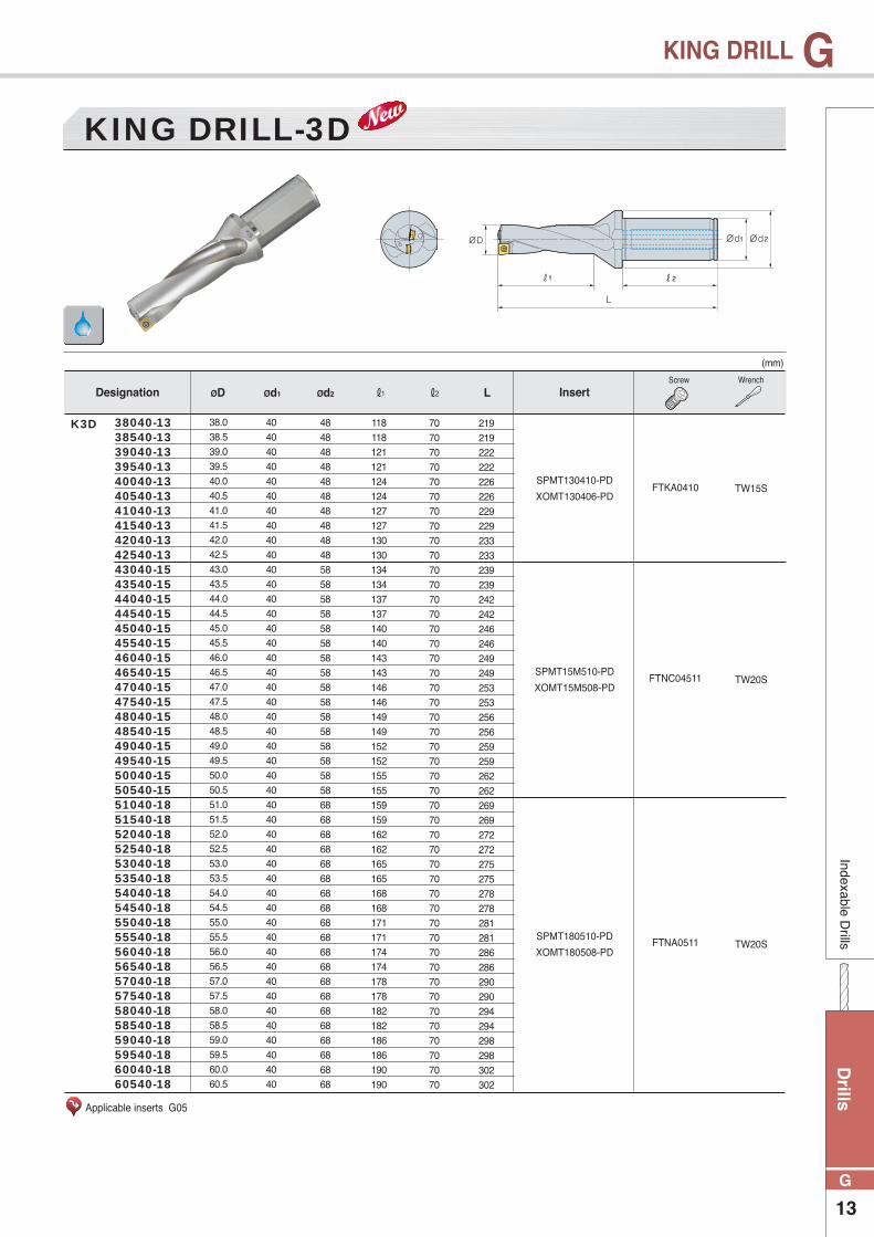
KING DRILL-3D
(mm)
Designation InsertScrew Wrench
ØD Ød1 Ød2 ℓ1 ℓ2 L
Applicable inserts G05
K3D
Drills
13
G
GIndexable D
rills
KING DRILL
38.038.539.039.540.040.541.041.542.042.543.043.544.044.545.045.546.046.547.047.548.048.549.049.550.050.551.051.552.052.553.053.554.054.555.055.556.056.557.057.558.058.559.059.560.060.5
40404040404040404040404040404040404040404040404040404040404040404040404040404040404040404040
48484848484848484848585858585858585858585858585858586868686868686868686868686868686868686868
118 118 121 121 124 124 127 127 130 130 134 134 137 137 140 140 143 143 146 146 149 149 152 152 155 155 159 159 162 162 165 165 168 168 171 171 174 174 178 178 182 182 186 186 190 190
70707070707070707070707070707070707070707070707070707070707070707070707070707070707070707070
219 219 222 222 226 226 229 229 233 233 239 239 242 242 246 246 249 249 253 253 256 256 259 259 262 262269 269 272 272 275 275 278 278 281 281 286 286 290 290 294 294 298 298 302 302
SPMT130410-PD
XOMT130406-PDFTKA0410 TW15S
SPMT15M510-PD
XOMT15M508-PDFTNC04511 TW20S
SPMT180510-PD
XOMT180508-PDFTNA0511 TW20S
38040-1338540-1339040-1339540-1340040-1340540-1341040-1341540-1342040-1342540-1343040-1543540-1544040-1544540-1545040-1545540-1546040-1546540-1547040-1547540-1548040-1548540-1549040-1549540-1550040-1550540-1551040-1851540-1852040-1852540-1853040-1853540-1854040-1854540-1855040-1855540-1856040-1856540-1857040-1857540-1858040-1858540-1859040-1859540-1860040-1860540-18
KING DRILL-3D
(mm)
Designation InsertScrew Wrench
K3D
ØD Ød1 Ød2 ℓ1 ℓ2 L
Applicable inserts G05
Dri
lls
14
G
GIn
dexa
ble
Dril
ls
KING DRILL
12.012.513.013.514.014.515.015.516.016.517.017.518.018.519.019.520.020.521.021.522.022.523.023.524.024.525.025.526.026.527.027.528.028.529.029.530.030.531.031.532.032.533.033.534.034.535.035.536.036.537.037.5
202020202020202020252525252525252525252525252525323232323232323232323232 32323232323232323232323240404040
25252525252525252534343434343434343434343434343444444444444444444444444444444444444444444444444448484848
51 51 55 55 59 59 63 63 67 67 71 71 75 75 79 79 83 83 87 87 91 91 95 95 99 99 103 103 107 107 111 111 115 115 119 119 123 123 127 127 131 131 135 135 139 139 143 143 148 148 152 152
50505050505050505056565656565656565656565656565660606060606060606060606060606060606060606060606070707070
115 115 119 119 124 124 129 129 133 139 143 143 148 148 152 152 158 158 162 162 166 166 172 172 181 181 185 185 189 189 194 194 199 199 203 203210 210 214 214 218 218 223 223 227 227 231 231 248 248 252 252
SPMT040204-PD
XOMT040204-PDFTNA0204 TW06S
SPMT050204-PD
XOMT050204-PDFTNA0204 TW06S
SPMT060205-PD
XOMT060204-PDFTKA02206S TW07S
SPMT07T208-PD
XOMT07T205-PDFTKA02565 TW07S
SPMT090308-PD
XOMT090305-PDFTKA0307 TW09S
SPMT11T308-PD
XOMT11T306-PDFTKA0307 TW15S
SPMT130410-PD
XOMT130406-PDFTKA0410 TW15S
12020-0412520-0413020-0413520-0414020-0514520-0515020-0515520-0516020-0516525-0617025-0617525-0618025-0618525-0619025-0619525-0620025-0720525-0721025-0721525-0722025-0722525-0723025-0723525-0724032-0924532-0925032-0925532-0926032-0926532-0927032-0927532-0928032-0928532-0929032-0929532-0930032-1130532-1131032-1131532-1132032-1132532-1133032-1133532-1134032-1134532-1135032-1135532-1136040-1336540-1337040-1337540-13
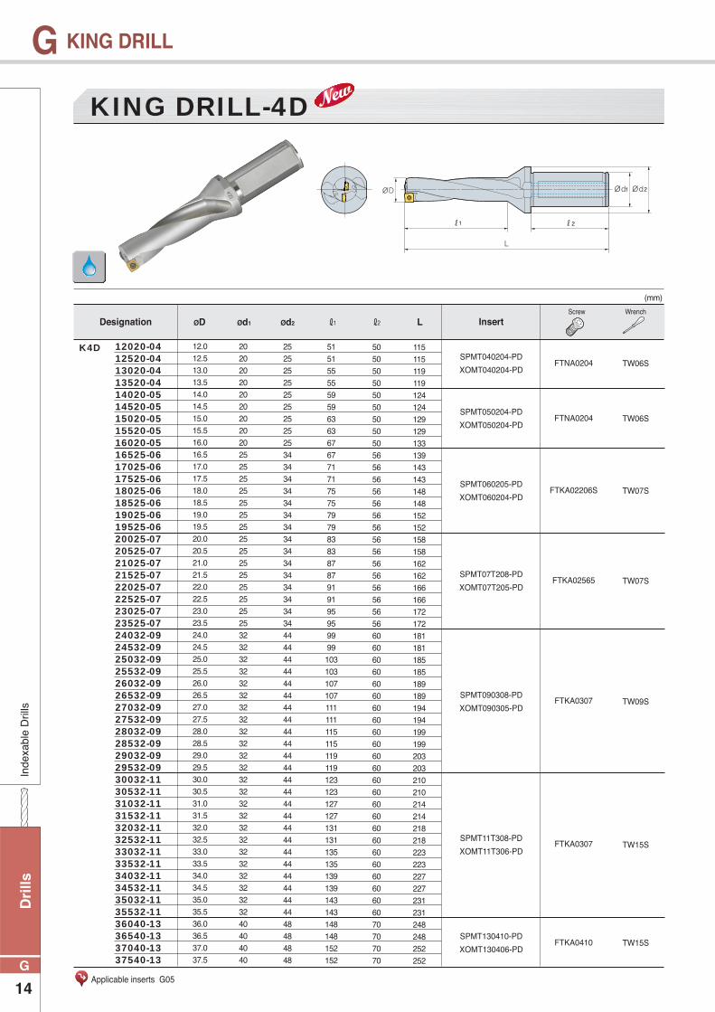
KING DRILL-4D
(mm)
Designation InsertScrew Wrench
ØD Ød1 Ød2 ℓ1 ℓ2 L
Applicable inserts G05
K4D

Drills
15
G
GIndexable D
rills
KING DRILL
38.038.539.039.540.040.541.041.542.042.543.043.544.044.545.045.546.046.547.047.548.048.549.049.550.050.551.051.552.052.553.053.554.054.555.055.556.056.557.057.558.058.559.059.560.060.5
40404040404040404040404040404040404040404040404040404040404040404040404040404040404040404040
48484848484848484848585858585858585858585858585858586868686868686868686868686868686868686868
156 156 160 160 164 164 168 168 172 172 177 177 181 181 185 185 189 189 193 193 197 197 201 201 205 205 210 210 214 214 218 218 222 222 226 226 230 230 235 235 240 240 245 245 250 250
70707070707070707070707070707070707070707070707070707070707070707070707070707070707070707070
257 257 261 261 266 266 270 270 275 275 282 282 286 286 291 291 295 295 300 300 304 304 308 308 312 312 320 320 324 324 328 328 332 332 336 336 342 342 347 347 352 352 357 357 362 362
SPMT130410-PD
XOMT130406-PDFTKA0410 TW15S
SPMT15M510-PD
XOMT15M508-PDFTNC04511 TW20S
SPMT180510-PD
XOMT180508-PDFTNA0511 TW20S
38040-1338540-1339040-1339540-1340040-1340540-1341040-1341540-1342040-1342540-1343040-1543540-1544040-1544540-1545040-1545540-1546040-1546540-1547040-1547540-1548040-1548540-1549040-1549540-1550040-1550540-1551040-1851540-1852040-1852540-1853040-1853540-1854040-1854540-1855040-1855540-1856040-1856540-1857040-1857540-1858040-1858540-1859040-1859540-1860040-1860540-18
KING DRILL-4D
(mm)
Designation InsertScrew Wrench
K4D
ØD Ød1 Ød2 ℓ1 ℓ2 L
Applicable inserts G05
Dri
lls
16
G
GIn
dexa
ble
Dril
ls
KING DRILL
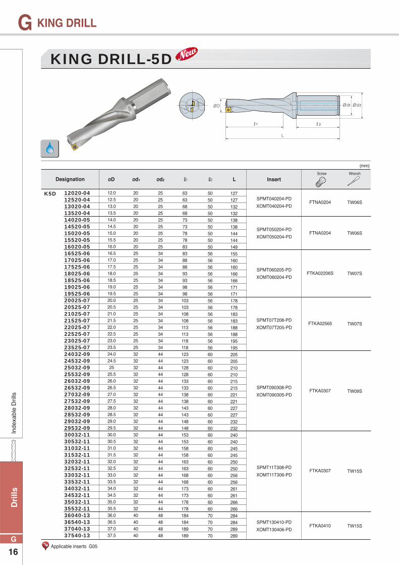
12.012.513.013.514.014.515.015.516.016.517.017.518.018.519.019.520.020.521.021.522.022.523.023.524.024.525
25.526.026.527.027.528.028.529.029.530.030.531.031.532.032.533.033.534.034.535.035.536.036.537.037.5
20202020202020202025252525252525252525252525252532323232323232323232323232323232323232323232323240404040
25252525252525252534343434343434343434343434343444444444444444444444444444444444444444444444444448484848
63 63 68 68 73 73 78 78 83 83 88 88 93 93 98 98 103 103 108 108 113 113 118 118 123 123 128 128 133 133 138 138 143 143 148 148 153 153 158 158 163 163 168 168 173 173 178 178 184 184 189 189
50505050505050505056565656565656565656565656565660606060606060606060606060606060606060606060606070707070
127 127 132 132 138 138 144 144 149 155 160 160 166 166 171 171 178 178 183 183 188 188 195 195 205 205 210 210 215 215 221 221 227 227 232 232 240 240 245 245 250 250 256 256 261 261 266 266 284 284 289 289
SPMT040204-PD
XOMT040204-PDFTNA0204 TW06S
SPMT050204-PD
XOMT050204-PDFTNA0204 TW06S
SPMT060205-PD
XOMT060204-PDFTKA02206S TW07S
SPMT07T208-PD
XOMT07T205-PDFTKA02565 TW07S
SPMT090308-PD
XOMT090305-PDFTKA0307 TW09S
SPMT11T308-PD
XOMT11T306-PDFTKA0307 TW15S
SPMT130410-PD
XOMT130406-PDFTKA0410 TW15S
12020-0412520-0413020-0413520-0414020-0514520-0515020-0515520-0516020-0516525-0617025-0617525-0618025-0618525-0619025-0619525-0620025-0720525-0721025-0721525-0722025-0722525-0723025-0723525-0724032-0924532-0925032-0925532-0926032-0926532-0927032-0927532-0928032-0928532-0929032-0929532-0930032-1130532-1131032-1131532-1132032-1132532-1133032-1133532-1134032-1134532-1135032-1135532-1136040-1336540-1337040-1337540-13
KING DRILL-5D
(mm)
Designation InsertScrew Wrench
ØD Ød1 Ød2 ℓ1 ℓ2 L
Applicable inserts G05
K5D
Drills
17
G
GIndexable D
rills
KING DRILL
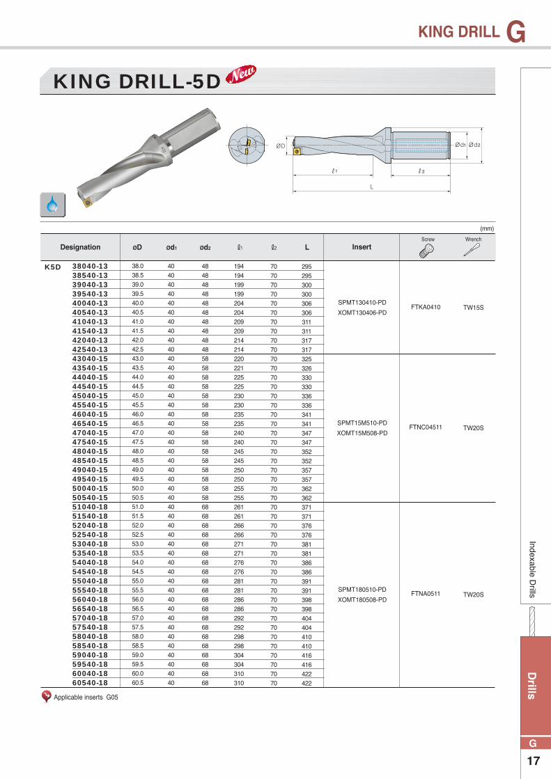
38.038.539.039.540.040.541.041.542.042.543.043.544.044.545.045.546.046.547.047.548.048.549.049.550.050.551.051.552.052.553.053.554.054.555.055.556.056.557.057.558.058.559.059.560.060.5
40404040404040404040404040404040404040404040404040404040404040404040404040404040404040404040
48484848484848484848585858585858585858585858585858586868686868686868686868686868686868686868
194 194 199 199 204 204 209 209 214 214 220 221 225 225 230 230 235 235 240 240 245 245 250 250 255 255 261 261 266 266 271 271 276 276 281 281 286 286 292 292 298 298 304 304 310 310
70707070707070707070707070707070707070707070707070707070707070707070707070707070707070707070
295 295 300 300 306 306 311 311 317 317 325 326 330 330 336 336 341 341 347 347 352 352 357 357 362 362 371 371 376 376 381 381 386 386 391 391 398 398 404 404 410 410 416 416 422 422
SPMT130410-PD
XOMT130406-PDFTKA0410 TW15S
SPMT15M510-PD
XOMT15M508-PDFTNC04511 TW20S
SPMT180510-PD
XOMT180508-PDFTNA0511 TW20S
38040-1338540-1339040-1339540-1340040-1340540-1341040-1341540-1342040-1342540-1343040-1543540-1544040-1544540-1545040-1545540-1546040-1546540-1547040-1547540-1548040-1548540-1549040-1549540-1550040-1550540-1551040-1851540-1852040-1852540-1853040-1853540-1854040-1854540-1855040-1855540-1856040-1856540-1857040-1857540-1858040-1858540-1859040-1859540-1860040-1860540-18
KING DRILL-5D
(mm)
Designation InsertScrew Wrench
K5D
ØD Ød1 Ød2 ℓ1 ℓ2 L
Applicable inserts G05
Dri
lls
18
G
GIndexable Drills
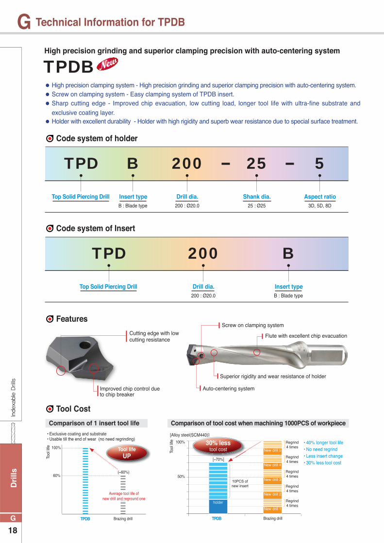
Technical Information for TPDB
Tool Cost
Features
Top Solid Piercing Drill Drill dia. Insert type200 : Ø20.0 B : Blade type
TPD 200 B
Code system of Insert
Top Solid Piercing Drill Drill dia. Shank dia. Aspect ratioInsert type200 : Ø20.0 25 : Ø25 3D, 5D, 8DB : Blade type
TPD 200 25 5B
Code system of holder
Improved chip control due to chip breaker
Auto-centering system
Superior rigidity and wear resistance of holder
Cutting edge with low cutting resistance
Screw on clamping system
Flute with excellent chip evacuation
Tool lifeUP
TPDB Brazing drill
(~60%)60%
100%
• Exclusive coating and substrate• Usable till the end of wear (no need regrinding)
Comparison of 1 insert tool life Comparison of tool cost when machining 1000PCS of workpiece
Average tool life ofnew drill and reground one
[Alloy steel(SCM440)]
[~70%]
10PCS ofnew insert
Regrind4 times
Brazing drill
100%
50%
TPDB
Regrind4 times
Regrind4 times
Regrind4 times
Regrind4 times
holder
New drill 1
New drill 2
New drill 3
New drill 4
New drill 5
• 40% longer tool life• No need regrind• Less insert change• 30% less tool cost
Tool
life
Tool
life
SCM440)]
30% lesstool cost
TPDBHigh precision grinding and superior clamping precision with auto-centering system
● High precision clamping system - High precision grinding and superior clamping precision with auto-centering system. ● Screw on clamping system - Easy clamping system of TPDB insert. ● Sharp cutting edge - Improved chip evacuation, low cutting load, longer tool life with ultra-fine substrate and
exclusive coating layer. ● Holder with excellent durability - Holder with high rigidity and superb wear resistance due to special surface treatment.
Drills
19
G
GIndexable Drills
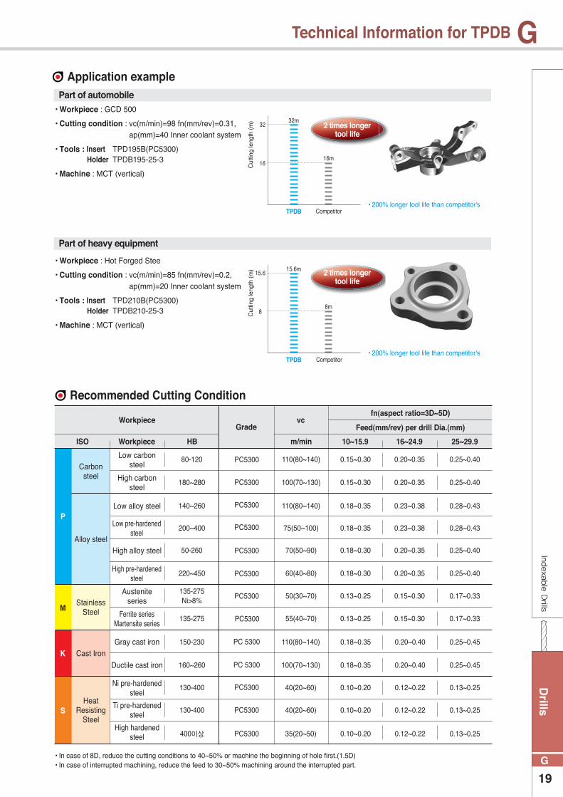
Technical Information for TPDB
Application examplePart of automobile
Part of heavy equipment
2 times longertool life
2 times longertool life
32m
15.6m
16m
8m
Cut
ting
leng
th (
m)
Cut
ting
leng
th (
m)
TPDB
TPDB
Competitor
Competitor
16
8
32
15.6
• 200% longer tool life than competitor's
• 200% longer tool life than competitor's
Recommended Cutting Condition
• In case of 8D, reduce the cutting conditions to 40~50% or machine the beginning of hole first.(1.5D)• In case of interrupted machining, reduce the feed to 30~50% machining around the interrupted part.
ISO
PC5300
PC5300
PC5300
PC5300
PC5300
PC5300
PC5300
PC5300
PC 5300
110(80~140)
100(70~130)
110(80~140)
75(50~100)
70(50~90)
60(40~80)
50(30~70)
55(40~70)
0.15~0.30
0.15~0.30
0.18~0.35
0.18~0.35
0.18~0.30
0.18~0.30
0.13~0.25
0.13~0.25
0.20~0.35
0.20~0.35
0.23~0.38
0.23~0.38
0.20~0.35
0.20~0.35
0.15~0.30
0.15~0.30
0.25~0.40
0.25~0.40
0.28~0.43
0.28~0.43
0.25~0.40
0.25~0.40
0.17~0.33
0.17~0.33
80-120
P
K
S
M
180~280
140~260
200~400
50-260
220~450
135-275 Ni>8%
135-275
PC5300
PC 5300
PC5300
PC5300
10~15.9Workpiece
Carbon steel
Alloy steel
Stainless Steel
Cast Iron
Heat Resisting
Steel
Low carbon steel
High carbon steel
Low alloy steel
Low pre-hardened steel
High alloy steel
High pre-hardened steel
Austenite series
Gray cast iron
Ductile cast iron
Ni pre-hardened steel
Ti pre-hardened steel
High hardened steel
150-230
160~260
130-400
130-400
400이상
110(80~140)
100(70~130)
40(20~60)
40(20~60)
35(20~50)
0.18~0.35
0.18~0.35
0.10~0.20
0.10~0.20
0.10~0.20
0.20~0.40
0.20~0.40
0.12~0.22
0.12~0.22
0.12~0.22
0.25~0.45
0.25~0.45
0.13~0.25
0.13~0.25
0.13~0.25
Ferrite seriesMartensite series
16~24.9HB 25~29.9m/min
GradeWorkpiece vc
fn(aspect ratio=3D~5D)
Feed(mm/rev) per drill Dia.(mm)
• Workpiece : GCD 500
• Cutting condition : vc(m/min)=98 fn(mm/rev)=0.31, ap(mm)=40 Inner coolant system
• Tools : Insert TPD195B(PC5300) Holder TPDB195-25-3
• Machine : MCT (vertical)
• Workpiece : Hot Forged Stee
• Cutting condition : vc(m/min)=85 fn(mm/rev)=0.2, ap(mm)=20 Inner coolant system
• Tools : Insert TPD210B(PC5300) Holder TPDB210-25-3
• Machine : MCT (vertical)

Dri
lls
20
G
GIn
dexa
ble
Dril
ls
Technical Information for TPDB
[Based on 5D][kW]
Drill Dia. [mm]
5
4
3
2
1
010 15 20 25 30
[Based on 5D][kN]
Drill Dia. [mm]
5
4
3
2
1
010 15 20 25 30
[Based on 5D][ℓ/min]
Cut
ting
oil q
uant
ity(Q
)C
uttin
g po
wer
(Pc)
Feed(Ft)
Pre
ssur
e of
cut
ting
oil(P
)
Drill Dia. [mm]
12
10
8
6
4
2
010 15 20 25 30
[Based on 5D][MPa]
Drill Dia. [mm]
1.4
1.2
1
0.8
0.6
0.4
0.2
010 15 20 25 30
Technical information
How to clamp a TPDB insert
Cutting oil quantity
Clamping an insert on a holder Changing an insert on the machine
Cutting power
Pressure of cutting oil
Feed
[Fig.1] [Fig.2] [Fig.3]
- Put an insert in the holder.
- As the Fig.1, clamp the insert while pushing it to
the V shaped groove of the holder.
- Screw the insert.
- Separate the insert from the holder.
- As the Fig.2, clean the insert seat
- Place the insert to the mounting seat.
- As the Fig.3, clamp the insert while pushing it to the V shaped
groove of the holder.
Drills
21
G
GIndexable D
rills
TPDB-Available Insert
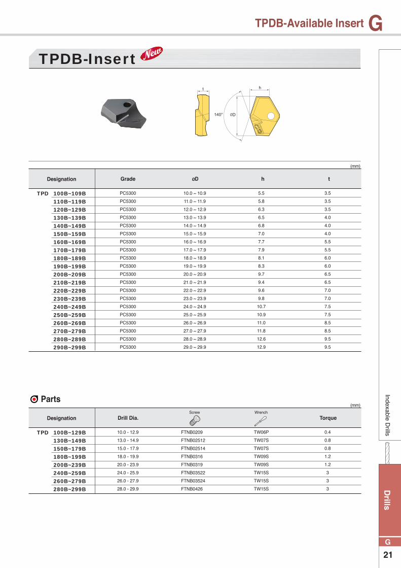
Parts
TPDB-Insert
100B~109B
110B~119B
120B~129B
130B~139B
140B~149B
150B~159B
160B~169B
170B~179B
180B~189B
190B~199B
200B~209B
210B~219B
220B~229B
230B~239B
240B~249B
250B~259B
260B~269B
270B~279B
280B~289B
290B~299B
100B~129B
130B~149B
150B~179B
180B~199B
200B~239B
240B~259B
260B~279B
280B~299B
TPD
TPD
(mm)
(mm)
10.0 ~ 10.9
11.0 ~ 11.9
12.0 ~ 12.9
13.0 ~ 13.9
14.0 ~ 14.9
15.0 ~ 15.9
16.0 ~ 16.9
17.0 ~ 17.9
18.0 ~ 18.9
19.0 ~ 19.9
20.0 ~ 20.9
21.0 ~ 21.9
22.0 ~ 22.9
23.0 ~ 23.9
24.0 ~ 24.9
25.0 ~ 25.9
26.0 ~ 26.9
27.0 ~ 27.9
28.0 ~ 28.9
29.0 ~ 29.9
FTNB0209
FTNB02512
FTNB02514
FTNB0316
FTNB0319
FTNB03522
FTNB03524
FTNB0426
PC5300
PC5300
PC5300
PC5300
PC5300
PC5300
PC5300
PC5300
PC5300
PC5300
PC5300
PC5300
PC5300
PC5300
PC5300
PC5300
PC5300
PC5300
PC5300
PC5300
10.0 - 12.9
13.0 - 14.9
15.0 - 17.9
18.0 - 19.9
20.0 - 23.9
24.0 - 25.9
26.0 - 27.9
28.0 - 29.9
5.5
5.8
6.3
6.5
6.8
7.0
7.7
7.9
8.1
8.3
9.7
9.4
9.6
9.8
10.7
10.9
11.0
11.8
12.6
12.9
TW06P
TW07S
TW07S
TW09S
TW09S
TW15S
TW15S
TW15S
3.5
3.5
3.5
4.0
4.0
4.0
5.5
5.5
6.0
6.0
6.5
6.5
7.0
7.0
7.5
7.5
8.5
8.5
9.5
9.5
0.4
0.8
0.8
1.2
1.2
3
3
3
Screw Wrench
ØDGrade
Drill Dia.
h t
Torque
Designation
Designation
Dri
lls
22
G
GIn
dexa
ble
Dril
ls
TPDB
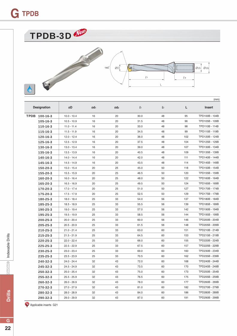
10.0 - 10.4
10.5 - 10.9
11.0 - 11.4
11.5 - 11.9
12.0 - 12.4
12.5 - 12.9
13.0 - 13.4
13.5 - 13.9
14.0 - 14.4
14.5 - 14.9
15.0 - 15.4
15.5 - 15.9
16.0 - 16.4
16.5 - 16.9
17.0 - 17.4
17.5 - 17.9
18.0 - 18.4
18.5 - 18.9
19.0 - 19.4
19.5 - 19.9
20.0 - 20.4
20.5 - 20.9
21.0 - 21.4
21.5 - 21.9
22.0 - 22.4
22.5 - 22.9
23.0 - 23.4
23.5 - 23.9
24.0 - 24.4
24.5 - 24.9
25.0 - 25.4
25.5 - 25.9
26.0 - 26.9
27.0 - 27.9
28.0 - 28.9
29.0 - 29.9
16
16
16
16
16
16
16
16
16
16
20
20
20
20
20
20
25
25
25
25
25
25
25
25
25
25
25
25
32
32
32
32
32
32
32
32
20
20
20
20
20
20
20
20
20
20
25
25
25
25
25
25
33
33
33
33
33
33
33
33
33
33
33
33
43
43
43
43
43
43
43
43
30.0
31.5
33.0
34.5
36.0
37.5
39.0
40.5
42.0
43.5
45.0
46.5
48.0
49.5
51.0
52.5
54.0
55.5
57.0
58.5
60.0
61.5
63.0
64.5
66.0
67.5
69.0
70.5
72.0
73.5
75.0
76.5
78.0
81.0
84.0
87.0
48
48
48
48
48
48
48
48
48
48
50
50
50
50
50
50
56
56
56
56
56
56
60
60
60
60
60
60
60
60
60
60
60
60
60
60
95
96
98
99
102
104
107
109
111
114
118
120
122
124
127
129
137
139
142
144
146
148
151
153
155
157
160
162
168
170
173
175
177
182
186
191
TPD100B - 104B
TPD105B - 109B
TPD110B - 114B
TPD115B - 119B
TPD120B - 124B
TPD125B - 129B
TPD130B - 134B
TPD135B - 139B
TPD140B - 144B
TPD145B - 149B
TPD150B - 154B
TPD155B - 159B
TPD160B - 164B
TPD165B - 169B
TPD170B - 174B
TPD175B - 179B
TPD180B - 184B
TPD185B - 189B
TPD190B - 194B
TPD195B - 199B
TPD200B - 204B
TPD205B - 209B
TPD210B - 214B
TPD215B - 219B
TPD220B - 224B
TPD225B - 229B
TPD230B - 234B
TPD235B - 239B
TPD240B - 244B
TPD245B - 249B
TPD250B - 254B
TPD255B - 259B
TPD260B - 269B
TPD270B - 279B
TPD280B - 289B
TPD290B - 299B
100-16-3
105-16-3
110-16-3
115-16-3
120-16-3
125-16-3
130-16-3
135-16-3
140-16-3
145-16-3
150-20-3
155-20-3
160-20-3
165-20-3
170-20-3
175-20-3
180-25-3
185-25-3
190-25-3
195-25-3
200-25-3
205-25-3
210-25-3
215-25-3
220-25-3
225-25-3
230-25-3
235-25-3
240-32-3
245-32-3
250-32-3
255-32-3
260-32-3
270-32-3
280-32-3
290-32-3
TPDB-3D
(mm)
Designation InsertØD Ød1 Ød2 ℓ1 ℓ2 L
Applicable inserts G21
TPDB

Drills
23
G
GIndexable D
rills
TPDB
10.0 - 10.4
10.5 - 10.9
11.0 - 11.4
11.5 - 11.9
12.0 - 12.4
12.5 - 12.9
13.0 - 13.4
13.5 - 13.9
14.0 - 14.4
14.5 - 14.9
15.0 - 15.4
15.5 - 15.9
16.0 - 16.4
16.5 - 16.9
17.0 - 17.4
17.5 - 17.9
18.0 - 18.4
18.5 - 18.9
19.0 - 19.4
19.5 - 19.9
20.0 - 20.4
20.5 - 20.9
21.0 - 21.4
21.5 - 21.9
22.0 - 22.4
22.5 - 22.9
23.0 - 23.4
23.5 - 23.9
24.0 - 24.4
24.5 - 24.9
25.0 - 25.4
25.5 - 25.9
26.0 - 26.9
27.0 - 27.9
28.0 - 28.9
29.0 - 29.9
16
16
16
16
16
16
16
16
16
16
20
20
20
20
20
20
25
25
25
25
25
25
25
25
25
25
25
25
32
32
32
32
32
32
32
32
20
20
20
20
20
20
20
20
20
20
25
25
25
25
25
25
33
33
33
33
33
33
33
33
33
33
33
33
43
43
43
43
43
43
43
43
50.0
52.5
55.0
57.5
60.0
62.5
65.0
67.5
70.0
72.5
75.0
77.5
80.0
82.5
85.0
87.5
90.0
92.5
95.0
97.5
100.0
102.5
105.0
107.5
110.0
112.5
115.0
117.5
120.0
122.5
125.0
127.5
130.0
135.0
140.0
145.0
48
48
48
48
48
48
48
48
48
48
50
50
50
50
50
50
56
56
56
56
56
56
60
60
60
60
60
60
60
60
60
60
60
60
60
60
115
117
120
123
126
129
133
136
139
143
148
151
154
157
161
164
173
176
180
183
186
189
193
196
199
202
206
209
216
219
223
226
229
236
242
249
TPD100B - 104B
TPD105B - 109B
TPD110B - 114B
TPD115B - 119B
TPD120B - 124B
TPD125B - 129B
TPD130B - 134B
TPD135B - 139B
TPD140B - 144B
TPD145B - 149B
TPD150B - 154B
TPD155B - 159B
TPD160B - 164B
TPD165B - 169B
TPD170B - 174B
TPD175B - 179B
TPD180B - 184B
TPD185B - 189B
TPD190B - 194B
TPD195B - 199B
TPD200B - 204B
TPD205B - 209B
TPD210B - 214B
TPD215B - 219B
TPD220B - 224B
TPD225B - 229B
TPD230B - 234B
TPD235B - 239B
TPD240B - 244B
TPD245B - 249B
TPD250B - 254B
TPD255B - 259B
TPD260B - 269B
TPD270B - 279B
TPD280B - 289B
TPD290B - 299B
100-16-5
105-16-5
110-16-5
115-16-5
120-16-5
125-16-5
130-16-5
135-16-5
140-16-5
145-16-5
150-20-5
155-20-5
160-20-5
165-20-5
170-20-5
175-20-5
180-25-5
185-25-5
190-25-5
195-25-5
200-25-5
205-25-5
210-25-5
215-25-5
220-25-5
225-25-5
230-25-5
235-25-5
240-32-5
245-32-5
250-32-5
255-32-5
260-32-5
270-32-5
280-32-5
290-32-5
TPDB-5D
(mm)
Designation InsertØD Ød1 Ød2 ℓ1 ℓ2 L
Applicable inserts G21
TPDB

Dri
lls
24
G
GIn
dexa
ble
Dril
ls
TPDB
10.0 - 10.4
10.5 - 10.9
11.0 - 11.4
11.5 - 11.9
12.0 - 12.4
12.5 - 12.9
13.0 - 13.4
13.5 - 13.9
14.0 - 14.4
14.5 - 14.9
15.0 - 15.4
15.5 - 15.9
16.0 - 16.4
16.5 - 16.9
17.0 - 17.4
17.5 - 17.9
18.0 - 18.4
18.5 - 18.9
19.0 - 19.4
19.5 - 19.9
20.0 - 20.4
20.5 - 20.9
21.0 - 21.4
21.5 - 21.9
22.0 - 22.4
22.5 - 22.9
23.0 - 23.4
23.5 - 23.9
24.0 - 24.4
24.5 - 24.9
25.0 - 25.4
25.5 - 25.9
26.0 - 26.9
27.0 - 27.9
28.0 - 28.9
29.0 - 29.9
16
16
16
16
16
16
16
16
16
16
20
20
20
20
20
20
25
25
25
25
25
25
25
25
25
25
25
25
32
32
32
32
32
32
32
32
20
20
20
20
20
20
20
20
20
20
25
25
25
25
25
25
33
33
33
33
33
33
33
33
33
33
33
33
43
43
43
43
43
43
43
43
80
84
88
92
96
100
104
108
112
116
120
124
128
132
136
140
144
148
152
156
160
164
168
172
176
180
184
188
192
196
200
204
208
216
224
232
48
48
48
48
48
48
48
48
48
48
50
50
50
50
50
50
56
56
56
56
56
56
60
60
60
60
60
60
60
60
60
60
60
60
60
60
145.0
149.0
153.0
157.0
162.0
166.5
172.0
176.5
181.0
186.5
193.0
197.5
202.0
206.5
212.0
216.5
227.0
231.5
237.0
241.5
246.0
250.5
256.0
260.5
265.0
269.5
275.0
279.5
288.0
292.5
298.0
302.5
307.0
317.0
326.0
336.0
TPD100B - 104B
TPD105B - 109B
TPD110B - 114B
TPD115B - 119B
TPD120B - 124B
TPD125B - 129B
TPD130B - 134B
TPD135B - 139B
TPD140B - 144B
TPD145B - 149B
TPD150B - 154B
TPD155B - 159B
TPD160B - 164B
TPD165B - 169B
TPD170B - 174B
TPD175B - 179B
TPD180B - 184B
TPD185B - 189B
TPD190B - 194B
TPD195B - 199B
TPD200B - 204B
TPD205B - 209B
TPD210B - 214B
TPD215B - 219B
TPD220B - 224B
TPD225B - 229B
TPD230B - 234B
TPD235B - 239B
TPD240B - 244B
TPD245B - 249B
TPD250B - 254B
TPD255B - 259B
TPD260B - 269B
TPD270B - 279B
TPD280B - 289B
TPD290B - 299B
100-16-8
105-16-8
110-16-8
115-16-8
120-16-8
125-16-8
130-16-8
135-16-8
140-16-8
145-16-8
150-20-8
155-20-8
160-20-8
165-20-8
170-20-8
175-20-8
180-25-8
185-25-8
190-25-8
195-25-8
200-25-8
205-25-8
210-25-8
215-25-8
220-25-8
225-25-8
230-25-8
235-25-8
240-32-8
245-32-8
250-32-8
255-32-8
260-32-8
270-32-8
280-32-8
290-32-8
TPDB-8D
(mm)
Designation InsertØD Ød1 Ød2 ℓ1 ℓ2 L
Applicable inserts G21
TPDB
Drills
25
G
GIndexable D
rills
Technical Information for WPDC
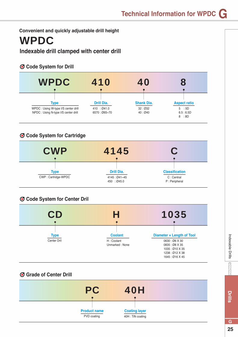
Indexable drill clamped with center drill
Type
Type
Type
Product name
Drill Dia.
Drill Dia.
Coolant
Classification
Diameter × Length of Tool
Coating layer
Aspect ratioShank Dia.410 : Ø41.06570 : Ø65~70
WPDC : Using W-type I/S center drillNPDC : Using N-type I/S center drill
CWP : Cartridge-WPDC
Center Dril
PVD coating
4145 : Ø41~45450 : Ø45.0
H : CoolantUnmarked : None
C : CentralP : Peripheral
0630 : Ø6 X 300835 : Ø8 X 351035 : Ø10 X 351238 : Ø12 X 381645 : Ø16 X 45
40H : TiN coating
5 : 5D6.5 : 6.5D8 : 8D
32 : Ø3240 : Ø40
WPDC
CWP
CD
PC
410
4145
H
C
1035
40H
840
Code System for Drill
Code System for Cartridge
Code System for Center Dril
Grade of Center Drill
WPDC Convenient and quickly adjustable drill height
Dri
lls
26
G
G Technical Information for WPDCIn
dexa
ble
Dril
ls
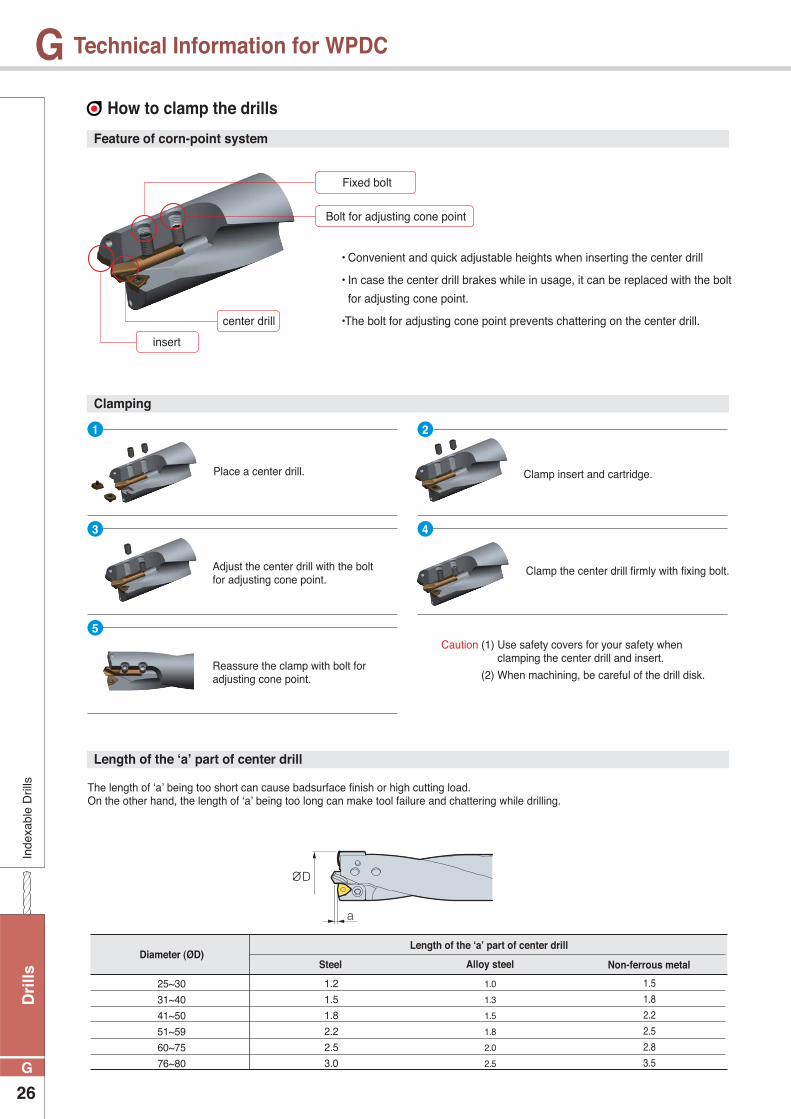
How to clamp the drills
Feature of corn-point system
Clamping
Length of the ‘a’ part of center drill
• Convenient and quick adjustable heights when inserting the center drill
• In case the center drill brakes while in usage, it can be replaced with the bolt
for adjusting cone point.
•The bolt for adjusting cone point prevents chattering on the center drill.
The length of ‘a’ being too short can cause badsurface finish or high cutting load.On the other hand, the length of ‘a’ being too long can make tool failure and chattering while drilling.
Place a center drill. Clamp insert and cartridge.
Adjust the center drill with the bolt for adjusting cone point.
Clamp the center drill firmly with fixing bolt.
Reassure the clamp with bolt for adjusting cone point.
insert
center drill
Fixed bolt
Bolt for adjusting cone point
1
3
5
2
4
Caution (1) Use safety covers for your safety when clamping the center drill and insert.
(2) When machining, be careful of the drill disk.
Length of the ‘a’ part of center drillDiameter (ØD)
Steel Alloy steel Non-ferrous metal
1.5
1.8
2.2
2.5
2.8
3.5
25~30
31~40
41~50
51~59
60~75
76~80
1.2
1.5
1.8
2.2
2.5
3.0
1.0
1.3
1.5
1.8
2.0
2.5
Drills
27
G
GIndexable D
rills
Technical Information for WPDC
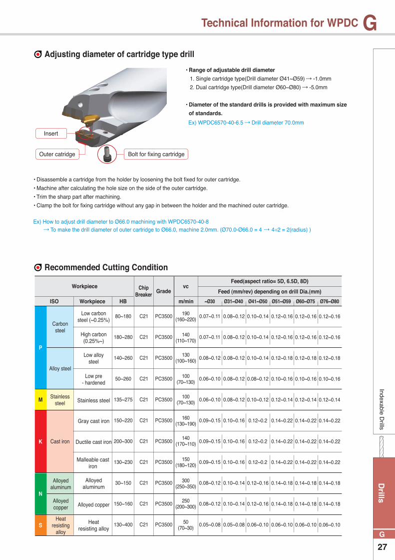
Adjusting diameter of cartridge type drill
• Disassemble a cartridge from the holder by loosening the bolt fixed for outer cartridge.
• Machine after calculating the hole size on the side of the outer cartridge.
• Trim the sharp part after machining.
• Clamp the bolt for fixing cartridge without any gap in between the holder and the machined outer cartridge.
Ex) How to adjust drill diameter to Ø66.0 machining with WPDC6570-40-8 To make the drill diameter of outer cartridge to Ø66.0, machine 2.0mm. (Ø70.0-Ø66.0 = 4 4÷2 = 2(radius) )
• Range of adjustable drill diameter
1. Single cartridge type(Drill diameter Ø41~Ø59) -1.0mm
2. Dual cartridge type(Drill diameter Ø60~Ø80) -5.0mm
• Diameter of the standard drills is provided with maximum size
of standards.
Ex) WPDC6570-40-6.5 Drill diameter 70.0mm
Insert
Outer catridge Bolt for fixing cartridge
Recommended Cutting Condition
ISO
P
K
N
S
M
~Ø30 Ø31~Ø40 Ø41~Ø50 Ø51~Ø59 Ø60~Ø75 Ø76~Ø80Workpiece
Carbon steel
Alloy steel
Stainless steel
Cast iron
Heat resisting
alloy
Alloyed aluminum
Alloyed copper
190(160~220)
100(70~130)
130(100~160)
140(170~110)
250(200~300)
140(110~170)
160(130~190)
300(250~350)
100(70~130)
150(180~120)
50(70~30)
80~180
180~280
140~260
50~260
135~275
150~220
200~300
130~230
30~150
150~160
130~400
C21
C21
C21
C21
C21
C21
C21
C21
C21
C21
C21
PC3500
PC3500
PC3500
PC3500
PC3500
PC3500
PC3500
PC3500
PC3500
PC3500
PC3500
0.07~0.11
0.07~0.11
0.08~0.12
0.06~0.10
0.06~0.10
0.09~0.15
0.09~0.15
0.09~0.15
0.08~0.12
0.08~0.12
0.05~0.08
0.08~0.12
0.08~0.12
0.08~0.12
0.08~0.12
0.08~0.12
0.10~0.16
0.10~0.16
0.10~0.16
0.10~0.14
0.10~0.14
0.05~0.08
0.10~0.14
0.10~0.14
0.10~0.14
0.08~0.12
0.10~0.12
0.12~0.2
0.12~0.2
0.12~0.2
0.12~0.16
0.12~0.16
0.06~0.10
0.12~0.16
0.12~0.16
0.12~0.18
0.10~0.16
0.12~0.14
0.14~0.22
0.14~0.22
0.14~0.22
0.14~0.18
0.14~0.18
0.06~0.10
0.12~0.16
0.12~0.16
0.12~0.18
0.10~0.16
0.12~0.14
0.14~0.22
0.14~0.22
0.14~0.22
0.14~0.18
0.14~0.18
0.06~0.10
0.12~0.16
0.12~0.16
0.12~0.18
0.10~0.16
0.12~0.14
0.14~0.22
0.14~0.22
0.14~0.22
0.14~0.18
0.14~0.18
0.06~0.10
Low carbonsteel (~0.25%)
Low pre- hardened
Ductile cast iron
High carbon(0.25%~)
Stainless steel
Malleable cast iron
Alloyed copper
Low alloy steel
Gray cast iron
Alloyed aluminum
Heat resisting alloy
HB m/min
GradeChip
BreakerWorkpiece vc
Feed (mm/rev) depending on drill Dia.(mm)
Feed(aspect ratio= 5D, 6.5D, 8D)

Dri
lls
28
G
GIn
dexa
ble
Dril
ls
Center Drill
Inner outer
catridgeCenter drillInsert
Screw fixed boltCenter drillWrench cone point bolt
fixed boltDeaignation
InsertØD
25
26~28
29~30
31~35
36~40
41
42
43
44
45
46
47
48
49
50
51
52
53
54
55
56
57
58
59
60~65
65~70
70~75
75~80
WPDC250-32-�WPDC260~280-32-�WPDC290~300-32-�WPDC310~350-32-�WPDC360~400-32-�WPDC410-40-�WPDC420-40-�WPDC430-40-�WPDC440-40-�WPDC450-40-�WPDC460-40-�WPDC470-40-�WPDC480-40-�WPDC490-40-�WPDC500-40-�WPDC510-40-�WPDC520-40-�WPDC530-40-�WPDC540-40-�WPDC550-40-�WPDC560-40-�WPDC570-40-�WPDC580-40-�WPDC590-40-�WPDC6065-40-�WPDC6570-40-�WPDC7075-40-�WPDC7580-40-�
KHA0508
KHA0510
KHA0610
KHA0612
KHA0812
KHA0815
KHA1015
KHA1020
CD0630
CD0835
CDH1035
CDH1238
CDH1645
CWP4145C
CWP4650C
CWP5155C
CWP5659C
CWP6065C
CWP6570C
CWP7075C
CWP7580C
CWP410P
CWP420P
CWP430P
CWP440P
CWP450P
CWP460P
CWP470P
CWP480P
CWP490P
CWP500P
CWP510P
CWP520P
CWP530P
CWP540P
CWP550P
CWP560P
CWP570P
CWP580P
CWP590P
CWP6065P
CWP6570P
CWP7075P
CWP7580T
BHA0510
BHA0512
BHA0612
BHA0614
BHA0510
BHA0612
FTKA02206
FTKA02565
FTKA0307
FTKA03508
FTKA0411K
FTKA0307
FTKA03508
WC�T030204-C21
WC�T040204-C21
WC�T050308-C21
WC�T06T308-C21
WC�T080408-C21
WC�T050308-C21
WC�T06T308-C21
TW06S
TW07S
TW09S
TW15S
TW15S
TW09S
TW15S
KHC0510
KHC0610
KHC0812
KHC1016
KHC1020
Parts of WPDC type indexable drills
6
8
10
12
16
30
35
35
38
45
무
무
유
유
유
PC40H
PC40H
PC40H
PC40H
PC40H
CD 0630
CD 0835
CDH 1035
CDH 1238
CDH 1645
Center drill
(mm)
Designation Oil-holeGrade ØD L
Applicable inserts G05
• This is HSS with Tin coating
Drills
29
G
GIndexable D
rills
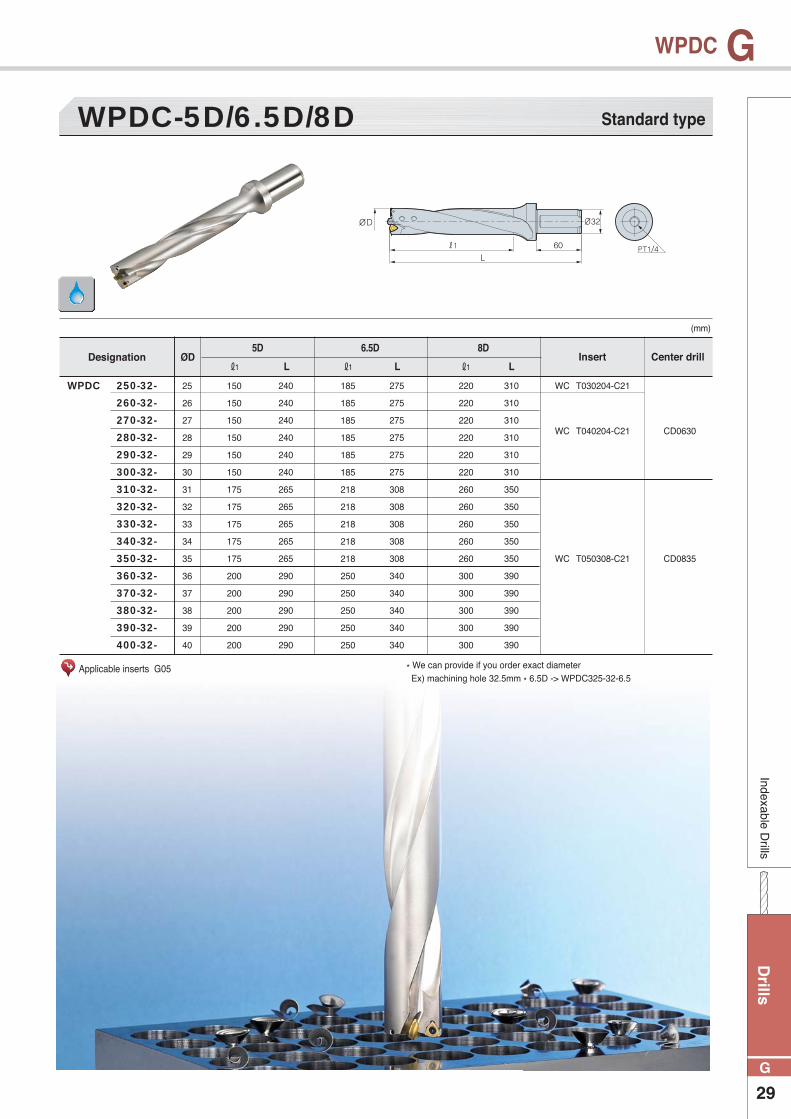
WPDC
WPDC-5D/6.5D/8D
(mm)
Applicable inserts G05
Standard type
WPDC 250-32-�
260-32-�
270-32-�
280-32-�
290-32-�
300-32-�
310-32-�
320-32-�
330-32-�
340-32-�
350-32-�
360-32-�
370-32-�
380-32-�
390-32-�
400-32-�
Designation Insert Center drill
150
150
150
150
150
150
175
175
175
175
175
200
200
200
200
200
185
185
185
185
185
185
218
218
218
218
218
250
250
250
250
250
220
220
220
220
220
220
260
260
260
260
260
300
300
300
300
300
240
240
240
240
240
240
265
265
265
265
265
290
290
290
290
290
275
275
275
275
275
275
308
308
308
308
308
340
340
340
340
340
310
310
310
310
310
310
350
350
350
350
350
390
390
390
390
390
ØD
25
26
27
28
29
30
31
32
33
34
35
36
37
38
39
40
ℓ1 ℓ1 ℓ1L L L
5D 6.5D 8D
WC�T030204-C21
WC�T040204-C21
WC�T050308-C21
CD0630
CD0835
* We can provide if you order exact diameter Ex) machining hole 32.5mm * 6.5D -> WPDC325-32-6.5
Dri
lls
30
G
GIn
dexa
ble
Dril
ls
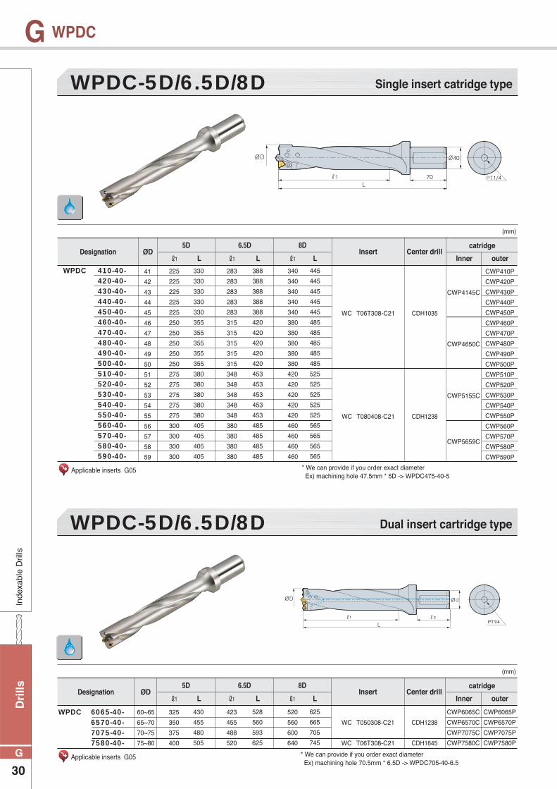
WPDC
WPDC-5D/6.5D/8D
WPDC-5D/6.5D/8D
(mm)
(mm)
Applicable inserts G05
Applicable inserts G05
Single insert catridge type
Dual insert cartridge type
WPDC 410-40-� 420-40-� 430-40-� 440-40-� 450-40-� 460-40-� 470-40-� 480-40-� 490-40-� 500-40-� 510-40-� 520-40-� 530-40-� 540-40-� 550-40-� 560-40-� 570-40-� 580-40-� 590-40-�
WPDC 6065-40-� 6570-40-� 7075-40-� 7580-40-�
Designation
Designation
Insert
Insert
Center drill
Center drill
catridge
catridge
Inner
Inner
outer
outer
225
225
225
225
225
250
250
250
250
250
275
275
275
275
275
300
300
300
300
325
350
375
400
283
283
283
283
283
315
315
315
315
315
348
348
348
348
348
380
380
380
380
423
455
488
520
340
340
340
340
340
380
380
380
380
380
420
420
420
420
420
460
460
460
460
520
560
600
640
330
330
330
330
330
355
355
355
355
355
380
380
380
380
380
405
405
405
405
430
455
480
505
388
388
388
388
388
420
420
420
420
420
453
453
453
453
453
485
485
485
485
528
560
593
625
445
445
445
445
445
485
485
485
485
485
525
525
525
525
525
565
565
565
565
625
665
705
745
ØD
ØD
41
42
43
44
45
46
47
48
49
50
51
52
53
54
55
56
57
58
59
60~65
65~70
70~75
75~80
CWP410P
CWP420P
CWP430P
CWP440P
CWP450P
CWP460P
CWP470P
CWP480P
CWP490P
CWP500P
CWP510P
CWP520P
CWP530P
CWP540P
CWP550P
CWP560P
CWP570P
CWP580P
CWP590P
CWP6065P
CWP6570P
CWP7075P
CWP7580P
CWP4145C
CWP4650C
CWP5155C
CWP5659C
CWP6065C
CWP6570C
CWP7075C
CWP7580C
ℓ1
ℓ1
ℓ1
ℓ1
ℓ1
ℓ1
L
L
L
L
L
L
5D
5D
6.5D
6.5D
8D
8D
WC�T06T308-C21
WC�T080408-C21
WC�T050308-C21
WC�T06T308-C21
CDH1035
CDH1238
CDH1238
CDH1645
* We can provide if you order exact diameter Ex) machining hole 47.5mm * 5D -> WPDC475-40-5
* We can provide if you order exact diameter Ex) machining hole 70.5mm * 6.5D -> WPDC705-40-6.5
Drills
31
G
GS
olid drill
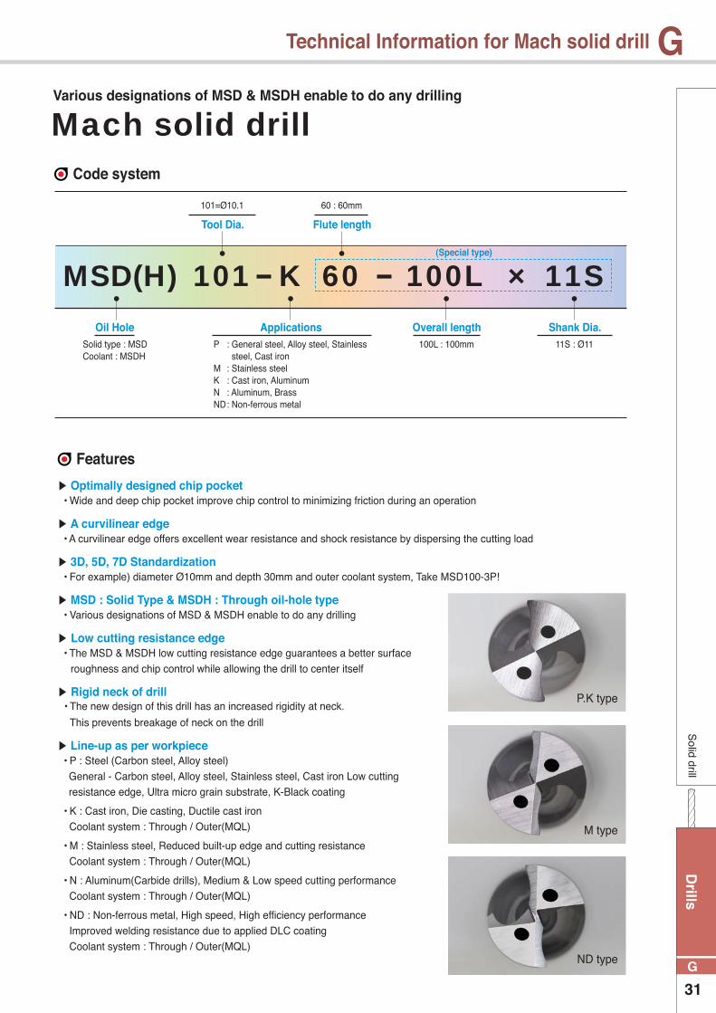
Technical Information for Mach solid drill
Oil Hole Applications Overall length Shank Dia.
Tool Dia. Flute length
(Special type)
P : General steel, Alloy steel, Stainless steel, Cast iron
M : Stainless steelK : Cast iron, AluminumN : Aluminum, BrassND : Non-ferrous metal
100L : 100mm 11S : Ø11
101=Ø10.1 60 : 60mm
Solid type : MSDCoolant : MSDH
MSD(H) K 60 100L × 11S101
Code system
Features
Optimally designed chip pocket • Wide and deep chip pocket improve chip control to minimizing friction during an operation
A curvilinear edge • A curvilinear edge offers excellent wear resistance and shock resistance by dispersing the cutting load
3D, 5D, 7D Standardization • For example) diameter Ø10mm and depth 30mm and outer coolant system, Take MSD100-3P!
MSD : Solid Type & MSDH : Through oil-hole type • Various designations of MSD & MSDH enable to do any drilling
Low cutting resistance edge • The MSD & MSDH low cutting resistance edge guarantees a better surface roughness and chip control while allowing the drill to center itself
Rigid neck of drill • The new design of this drill has an increased rigidity at neck.
This prevents breakage of neck on the drill
Line-up as per workpiece • P : Steel (Carbon steel, Alloy steel) General - Carbon steel, Alloy steel, Stainless steel, Cast iron Low cutting resistance edge, Ultra micro grain substrate, K-Black coating
• K : Cast iron, Die casting, Ductile cast iron Coolant system : Through / Outer(MQL)
• M : Stainless steel, Reduced built-up edge and cutting resistance Coolant system : Through / Outer(MQL)
• N : Aluminum(Carbide drills), Medium & Low speed cutting performance Coolant system : Through / Outer(MQL)
• ND : Non-ferrous metal, High speed, High efficiency performance Improved welding resistance due to applied DLC coating Coolant system : Through / Outer(MQL)
P.K type
M type
ND type
Mach solid drillVarious designations of MSD & MSDH enable to do any drilling
Dri
lls
32
G
GS
olid
dril
l
Technical Information for Mach solid drill
Features
Specification line-up
Line-up as per workpiece
Cutting condition formula
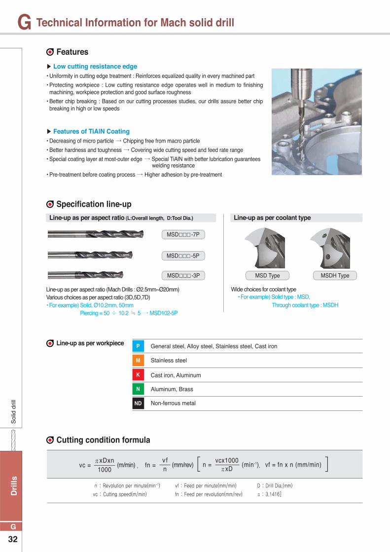
Low cutting resistance edge• Uniformity in cutting edge treatment : Reinforces equalized quality in every machined part
• Protecting workpiece : Low cutting resistance edge operates well in medium to finishing machining, workpiece protection and good surface roughness
• Better chip breaking : Based on our cutting processes studies, our drills assure better chip breaking in high or low speeds
Features of TiAlN Coating• Decreasing of micro particle Chipping free from macro particle
• Better hardness and toughness Covering wide cutting speed and feed rate range
• Special coating layer at most-outer edge Special TiAlN with better lubrication guarantees welding resistance
• Pre-treatment before coating process Higher adhesion by pre-treatment
Line-up as per aspect ratio (Mach Drills : Ø2.5mm~Ø20mm) Various choices as per aspect ratio (3D,5D,7D)• For example) Solid, Ø10.2mm, 50mm Piercing = 50 10.2 5 MSD102-5P
General steel, Alloy steel, Stainless steel, Cast iron
Stainless steel
Cast iron, Aluminum
Aluminum, Brass
Non-ferrous metal
Wide choices for coolant type • For example) Solid type : MSD, Through coolant type : MSDH
Line-up as per aspect ratio (L:Overall length, D:Tool Dia.) Line-up as per coolant type
MSD -5P
MSD -3P MSD Type MSDH Type
MSD -7P
P
M
K
N
ND
n : Revolution per minute(min-1) vf : Feed per minute(mm/min) D : Drill Dia.(mm)
vc : Cutting speed(m/min) fn : Feed per revolution(mm/rev) π : 3.1416]
(mm/rev)(m/min) , [ ] πxDxn1000
vc = vfnfn =
vcx1000πxD
n = (min-1), vf = fn x n (mm/min)
Drills
33
G
GS
olid drill
Technical Information for Mach solid drill
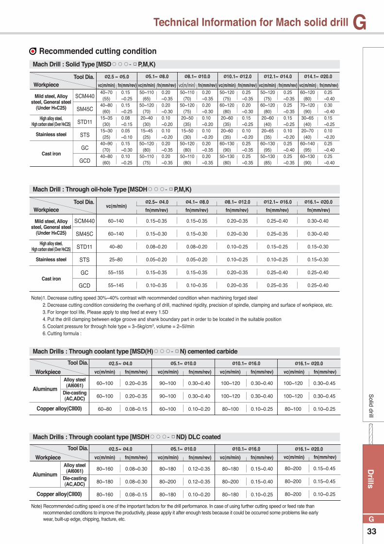
Recommended cutting condition
Mach Drill : Solid Type [MSD P,M,K)
Mach Drill : Through oil-hole Type [MSDH P,M,K)
Mach Drills : Through coolant type [MSD(H) N) cemented carbide
Mach Drills : Through coolant type [MSDH ND) DLC coated
WorkpieceTool Dia.
vc(m/min) vc(m/min) vc(m/min) vc(m/min) vc(m/min) vc(m/min)fn(mm/rev) fn(mm/rev) fn(mm/rev) fn(mm/rev) fn(mm/rev) fn(mm/rev)
Ø2.5 ~ Ø5.0 Ø5.1~ Ø8.0 Ø8.1~ Ø10.0 Ø10.1~ Ø12.0 Ø12.1~ Ø14.0 Ø14.1~ Ø20.0
Mild steel, Alloy steel, General steel
(Under HRC25)
Mild steel, Alloy steel, General steel
(Under HRC25)
High alloy steel, High carbon steel (Over HRC25)
High alloy steel, High carbon steel (Over HRC25)
Stainless steel
Stainless steel
Cast iron
Cast iron
SCM440
SM45C
STD11
STS
GC
GCD
40~70(55)
40~80(60)
15~35(30)
15~30(25)
40~90(70)
40~80(60)
0.15 ~0.25
0.15 ~0.25
0.08 ~0.15
0.05 ~0.10
0.15 ~0.30
0.10 ~0.25
50~110(65)
50~120(70)
20~40(30)
15~45(25)
50~120(80)
50~110(75)
0.20 ~0.35
0.20 ~0.30
0.10 ~0.20
0.10 ~0.20
0.20 ~0.35
0.20 ~0.35
50~110(70)
50~120(75)
20~50(35)
15~50(30)
50~120(80)
50~110(80)
0.20 ~0.35
0.20 ~0.30
0.10 ~0.20
0.10 ~0.20
0.20 ~0.35
0.20 ~0.35
50~120(75)
60~120(80)
20~60(35)
20~60(35)
60~130(90)
50~130(80)
0.25 ~0.35
0.20 ~0.30
0.15 ~0.25
0.10 ~0.20
0.25 ~0.35
0.25 ~0.35
50~120(75)
60~120(80)
20~60(40)
20~65(35)
60~130(95)
50~130(85)
0.25 ~0.35
0.25 ~0.35
0.15 ~0.25
0.10 ~0.20
0.25 ~0.40
0.25 ~0.35
60~120(80)
70~120(90)
30~65(40)
20~70(40)
60~140(95)
60~130(90)
0.25 ~0.40
0.30 ~0.40
0.15 ~0.25
0.10 ~0.20
0.25 ~0.40
0.25 ~0.40
fn(mm/rev) fn(mm/rev) fn(mm/rev) fn(mm/rev) fn(mm/rev)vc(m/min)
Ø2.5~ Ø4.0 Ø4.1~ Ø8.0 Ø8.1~ Ø12.0 Ø12.1~ Ø16.0 Ø16.1~ Ø20.0
SCM440
SM45C
STD11
STS
GC
GCD
60~140
60~140
40~80
25~80
55~155
55~145
0.15~0.35
0.15~0.30
0.08~0.20
0.05~0.20
0.15~0.35
0.10~0.35
0.15~0.35
0.15~0.30
0.08~0.20
0.05~0.20
0.15~0.35
0.10~0.35
0.20~0.35
0.20~0.30
0.10~0.25
0.10~0.25
0.20~0.35
0.20~0.35
0.25~0.40
0.25~0.35
0.15~0.25
0.10~0.25
0.25~0.40
0.25~0.35
0.30~0.40
0.30~0.40
0.15~0.30
0.15~0.30
0.25~0.40
0.25~0.40
Note) 1. Decrease cutting speed 30%~40% contrast with recommended condition when machining forged steel 2. Decrease cutting condition considering the overhang of drill, machined rigidity, precision of spindle, clamping and surface of workpiece, etc. 3. For longer tool life, Please apply to step feed at every 1.5D 4. Put the drill clamping between edge groove and shank boundary part in order to be located in the suitable position 5. Coolant pressure for through hole type = 3~5kg/cm3, volume = 2~5l/min 6. Cutting formula :
Note) Recommended cutting speed is one of the important factors for the drill performance. In case of using further cutting speed or feed rate than recommended conditions to improve the productivity, please apply it after enough tests because it could be occurred some problems like early wear, built-up edge, chipping, fracture, etc.
Workpiece
Workpiece
Tool Dia.
Tool Dia.
fn(mm/rev)
fn(mm/rev)
Ø2.5~ Ø4.0
Ø2.5~ Ø4.0
fn(mm/rev)
fn(mm/rev)
Ø5.1~ Ø10.0
Ø5.1~ Ø10.0
fn(mm/rev)
fn(mm/rev)
Ø10.1~ Ø16.0
Ø10.1~ Ø16.0
fn(mm/rev)
fn(mm/rev)
vc(m/min)
vc(m/min)
vc(m/min)
vc(m/min)
vc(m/min)
vc(m/min)
vc(m/min)
vc(m/min)
Ø16.1~ Ø20.0
Ø16.1~ Ø20.0
Aluminum
Aluminum
Alloy steel(AI6061)
Alloy steel(AI6061)
Die-casting(AC,ADC)
Die-casting(AC,ADC)
Copper alloy(CII00)
Copper alloy(CII00)
0.20~0.35
0.20~0.35
0.08~0.15
0.08~0.30
0.08~0.30
0.08~0.15
60~100
60~100
60~80
80~160
80~180
80~160
0.30~0.40
0.30~0.40
0.10~0.20
0.12~0.35
0.12~0.35
0.10~0.20
90~100
90~100
60~100
80~180
80~200
80~180
0.30~0.40
0.30~0.40
0.10~0.25
0.15~0.40
0.15~0.40
0.10~0.25
100~120
100~120
80~100
80~180
80~200
80~180
0.30~0.45
0.30~0.45
0.10~0.25
0.15~0.45
0.15~0.45
0.10~0.25
100~120
100~120
80~100
80~200
80~200
80~200
WorkpieceTool Dia.
Dri
lls
34
G
GS
olid
dril
l
Technical Information for Mach solid drill
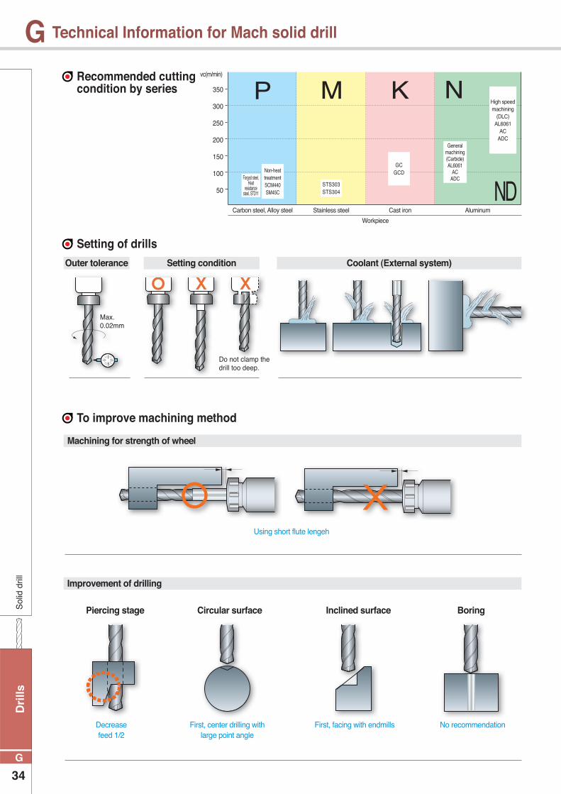
Recommended cutting condition by series
Setting of drills
To improve machining method
350
300
250
200
150
100
50
Carbon steel, Alloy steel Stainless steel
Workpiece
Cast iron Aluminum
vc(m/min)
P M K N
NDForged steel,
Heat resistance
steel, STD11
STS303STS304
GCGCDNon-heat
treatmentSCM440SM45C
General machining(Carbide)AL6061
ACADC
High speed machining
(DLC)AL6061
ACADC
Outer tolerance
Machining for strength of wheel
Improvement of drilling
Using short flute lengeh
Piercing stage Circular surface Inclined surface Boring
Decreasefeed 1/2
First, center drilling with large point angle
First, facing with endmills No recommendation
Setting condition Coolant (External system)
Max.0.02mm
Do not clamp the drill too deep.
Drills
35
G
GS
olid drill
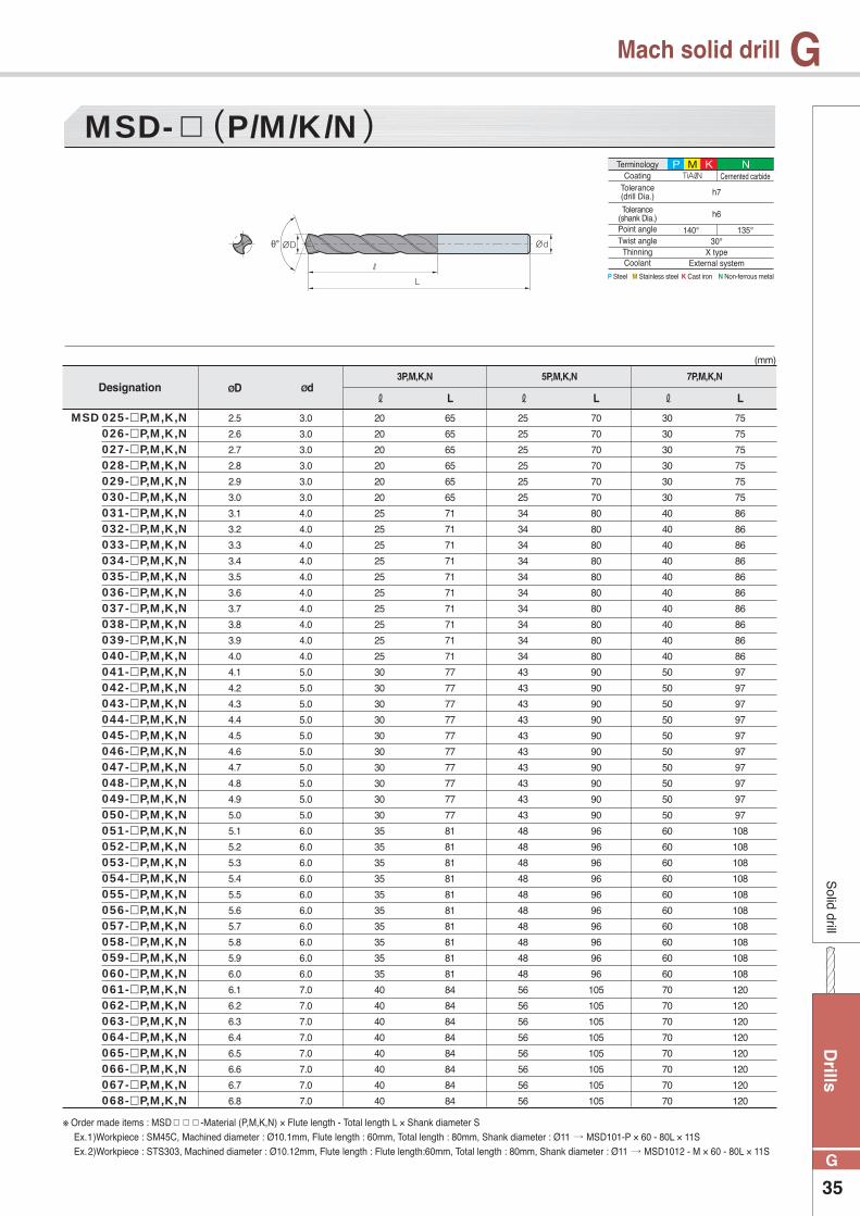
Mach solid drill
MSD- P/M/K/N
ØD Ød ℓ L
3P,M,K,N 5P,M,K,N 7P,M,K,N
ℓ L ℓ L
2.5
2.6
2.7
2.8
2.9
3.0
3.1
3.2
3.3
3.4
3.5
3.6
3.7
3.8
3.9
4.0
4.1
4.2
4.3
4.4
4.5
4.6
4.7
4.8
4.9
5.0
5.1
5.2
5.3
5.4
5.5
5.6
5.7
5.8
5.9
6.0
6.1
6.2
6.3
6.4
6.5
6.6
6.7
6.8
3.0
3.0
3.0
3.0
3.0
3.0
4.0
4.0
4.0
4.0
4.0
4.0
4.0
4.0
4.0
4.0
5.0
5.0
5.0
5.0
5.0
5.0
5.0
5.0
5.0
5.0
6.0
6.0
6.0
6.0
6.0
6.0
6.0
6.0
6.0
6.0
7.0
7.0
7.0
7.0
7.0
7.0
7.0
7.0
20
20
20
20
20
20
25
25
25
25
25
25
25
25
25
25
30
30
30
30
30
30
30
30
30
30
35
35
35
35
35
35
35
35
35
35
40
40
40
40
40
40
40
40
65
65
65
65
65
65
71
71
71
71
71
71
71
71
71
71
77
77
77
77
77
77
77
77
77
77
81
81
81
81
81
81
81
81
81
81
84
84
84
84
84
84
84
84
25
25
25
25
25
25
34
34
34
34
34
34
34
34
34
34
43
43
43
43
43
43
43
43
43
43
48
48
48
48
48
48
48
48
48
48
56
56
56
56
56
56
56
56
70
70
70
70
70
70
80
80
80
80
80
80
80
80
80
80
90
90
90
90
90
90
90
90
90
90
96
96
96
96
96
96
96
96
96
96
105
105
105
105
105
105
105
105
30
30
30
30
30
30
40
40
40
40
40
40
40
40
40
40
50
50
50
50
50
50
50
50
50
50
60
60
60
60
60
60
60
60
60
60
70
70
70
70
70
70
70
70
75
75
75
75
75
75
86
86
86
86
86
86
86
86
86
86
97
97
97
97
97
97
97
97
97
97
108
108
108
108
108
108
108
108
108
108
120
120
120
120
120
120
120
120
Designation
MSD 025- P,M,K,N 026- P,M,K,N 027- P,M,K,N 028- P,M,K,N 029- P,M,K,N 030- P,M,K,N 031- P,M,K,N 032- P,M,K,N 033- P,M,K,N 034- P,M,K,N 035- P,M,K,N 036- P,M,K,N 037- P,M,K,N 038- P,M,K,N 039- P,M,K,N 040- P,M,K,N 041- P,M,K,N 042- P,M,K,N 043- P,M,K,N 044- P,M,K,N 045- P,M,K,N 046- P,M,K,N 047- P,M,K,N 048- P,M,K,N 049- P,M,K,N 050- P,M,K,N 051- P,M,K,N 052- P,M,K,N 053- P,M,K,N 054- P,M,K,N 055- P,M,K,N 056- P,M,K,N 057- P,M,K,N 058- P,M,K,N 059- P,M,K,N 060- P,M,K,N 061- P,M,K,N 062- P,M,K,N 063- P,M,K,N 064- P,M,K,N 065- P,M,K,N 066- P,M,K,N 067- P,M,K,N 068- P,M,K,N
(mm)
※ Order made items : MSD -Material (P,M,K,N) × Flute length - Total length L × Shank diameter S Ex.1)Workpiece : SM45C, Machined diameter : Ø10.1mm, Flute length : 60mm, Total length : 80mm, Shank diameter : Ø11 MSD101-P × 60 - 80L × 11S Ex.2)Workpiece : STS303, Machined diameter : Ø10.12mm, Flute length : Flute length:60mm, Total length : 80mm, Shank diameter : Ø11 MSD1012 - M × 60 - 80L × 11S
P Steel M Stainless steel K Cast iron N Non-ferrous metal
TerminologyCoating
Point angleTwist angle
ThinningCoolant
Tolerance(drill Dia.)
Tolerance(shank Dia.)
TiAℓN
h7
h6
140°30°
X typeExternal system
Cernented carbide
135°
P M K N

Dri
lls
36
G
GS
olid
dril
l
Mach solid drill
MSD- P/M/K/N
ØD Ød ℓ L
3P,M,K,N 5P,M,K,N 7P,M,K,N
ℓ L ℓ L
6.9
7.0
7.1
7.2
7.3
7.4
7.5
7.6
7.7
7.8
7.9
8.0
8.1
8.2
8.3
8.4
8.5
8.6
8.7
8.8
8.9
9.0
9.1
9.2
9.3
9.4
9.5
9.6
9.7
9.8
9.9
10.0
10.1
10.2
10.3
10.4
10.5
10.6
10.7
10.8
10.9
11.0
11.1
11.2
7.0
7.0
8.0
8.0
8.0
8.0
8.0
8.0
8.0
8.0
8.0
8.0
9.0
9.0
9.0
9.0
9.0
9.0
9.0
9.0
9.0
9.0
10.0
10.0
10.0
10.0
10.0
10.0
10.0
10.0
10.0
10.0
11.0
11.0
11.0
11.0
11.0
11.0
11.0
11.0
11.0
11.0
12.0
12.0
40
40
45
45
45
45
45
45
45
45
45
45
48
48
48
48
48
48
48
48
48
48
52
52
52
52
52
52
52
52
52
52
56
56
56
56
56
56
56
56
56
56
60
60
84
84
90
90
90
90
90
90
90
90
90
90
97
97
97
97
97
97
97
97
97
97
106
106
106
106
106
106
106
106
106
106
111
111
111
111
111
111
111
111
111
111
118
118
56
56
60
60
60
60
60
60
60
60
60
60
72
72
72
72
72
72
72
72
72
72
75
75
75
75
75
75
75
75
75
75
83
83
83
83
83
83
83
83
83
83
90
90
105
105
105
110
110
110
110
110
110
110
110
110
125
125
125
125
125
125
125
125
125
125
129
129
129
129
129
129
129
129
129
129
140
140
140
140
140
140
140
140
140
140
148
148
70
70
80
80
80
80
80
80
80
80
80
80
90
90
90
90
90
90
90
90
90
90
95
95
95
95
95
95
95
95
95
95
105
105
105
105
105
105
105
105
105
105
114
114
120
120
120
130
130
130
130
130
130
130
130
130
143
143
143
143
143
143
143
143
143
143
150
150
150
150
150
150
150
150
150
150
160
160
160
160
160
160
160
160
160
160
172
172
Designation
MSD 069- P,M,K,N 070- P,M,K,N 071- P,M,K,N 072- P,M,K,N 073- P,M,K,N 074- P,M,K,N 075- P,M,K,N 076- P,M,K,N 077- P,M,K,N 078- P,M,K,N 079- P,M,K,N 080- P,M,K,N 081- P,M,K,N 082- P,M,K,N 083- P,M,K,N 084- P,M,K,N 085- P,M,K,N 086- P,M,K,N 087- P,M,K,N 088- P,M,K,N 089- P,M,K,N 090- P,M,K,N 091- P,M,K,N 092- P,M,K,N 093- P,M,K,N 094- P,M,K,N 095- P,M,K,N 096- P,M,K,N 097- P,M,K,N 098- P,M,K,N 099- P,M,K,N 100- P,M,K,N 101- P,M,K,N 102- P,M,K,N 103- P,M,K,N 104- P,M,K,N 105- P,M,K,N 106- P,M,K,N 107- P,M,K,N 108- P,M,K,N 109- P,M,K,N 110- P,M,K,N 111- P,M,K,N 112- P,M,K,N
(mm)
※ Order made items : MSD -Material (P,M,K,N) × Flute length - Total length L × Shank diameter S Ex.1)Workpiece : SM45C, Machined diameter : Ø10.1mm, Flute length : 60mm, Total length : 80mm, Shank diameter : Ø11 MSD101-P × 60 - 80L × 11S Ex.2)Workpiece : STS303, Machined diameter : Ø10.12mm, Flute length : Flute length:60mm, Total length : 80mm, Shank diameter : Ø11 MSD1012 - M × 60 - 80L × 11S
P Steel M Stainless steel K Cast iron N Non-ferrous metal
TerminologyCoating
Point angleTwist angle
ThinningCoolant
Tolerance(drill Dia.)
Tolerance(shank Dia.)
TiAℓN
h7
h6
140°30°
X typeExternal system
Cernented carbide
135°
P M K N
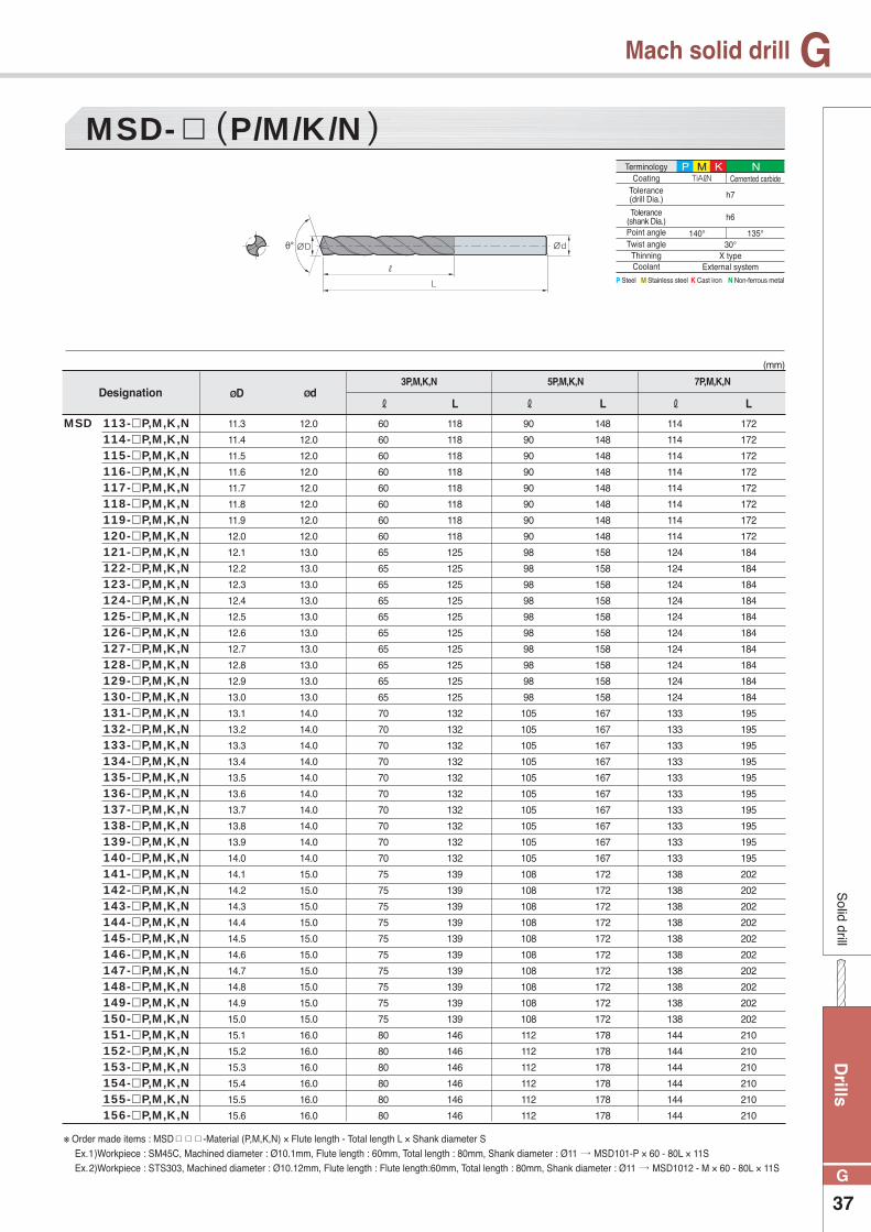
Drills
37
G
GS
olid drill
Mach solid drill
MSD- P/M/K/N
ØD Ød ℓ L
3P,M,K,N 5P,M,K,N 7P,M,K,N
ℓ L ℓ L
11.3
11.4
11.5
11.6
11.7
11.8
11.9
12.0
12.1
12.2
12.3
12.4
12.5
12.6
12.7
12.8
12.9
13.0
13.1
13.2
13.3
13.4
13.5
13.6
13.7
13.8
13.9
14.0
14.1
14.2
14.3
14.4
14.5
14.6
14.7
14.8
14.9
15.0
15.1
15.2
15.3
15.4
15.5
15.6
12.0
12.0
12.0
12.0
12.0
12.0
12.0
12.0
13.0
13.0
13.0
13.0
13.0
13.0
13.0
13.0
13.0
13.0
14.0
14.0
14.0
14.0
14.0
14.0
14.0
14.0
14.0
14.0
15.0
15.0
15.0
15.0
15.0
15.0
15.0
15.0
15.0
15.0
16.0
16.0
16.0
16.0
16.0
16.0
60
60
60
60
60
60
60
60
65
65
65
65
65
65
65
65
65
65
70
70
70
70
70
70
70
70
70
70
75
75
75
75
75
75
75
75
75
75
80
80
80
80
80
80
118
118
118
118
118
118
118
118
125
125
125
125
125
125
125
125
125
125
132
132
132
132
132
132
132
132
132
132
139
139
139
139
139
139
139
139
139
139
146
146
146
146
146
146
90
90
90
90
90
90
90
90
98
98
98
98
98
98
98
98
98
98
105
105
105
105
105
105
105
105
105
105
108
108
108
108
108
108
108
108
108
108
112
112
112
112
112
112
148
148
148
148
148
148
148
148
158
158
158
158
158
158
158
158
158
158
167
167
167
167
167
167
167
167
167
167
172
172
172
172
172
172
172
172
172
172
178
178
178
178
178
178
114
114
114
114
114
114
114
114
124
124
124
124
124
124
124
124
124
124
133
133
133
133
133
133
133
133
133
133
138
138
138
138
138
138
138
138
138
138
144
144
144
144
144
144
172
172
172
172
172
172
172
172
184
184
184
184
184
184
184
184
184
184
195
195
195
195
195
195
195
195
195
195
202
202
202
202
202
202
202
202
202
202
210
210
210
210
210
210
Designation
113- P,M,K,N114- P,M,K,N115- P,M,K,N116- P,M,K,N117- P,M,K,N118- P,M,K,N119- P,M,K,N120- P,M,K,N121- P,M,K,N122- P,M,K,N123- P,M,K,N124- P,M,K,N125- P,M,K,N126- P,M,K,N127- P,M,K,N128- P,M,K,N129- P,M,K,N130- P,M,K,N131- P,M,K,N132- P,M,K,N133- P,M,K,N134- P,M,K,N135- P,M,K,N136- P,M,K,N137- P,M,K,N138- P,M,K,N139- P,M,K,N140- P,M,K,N141- P,M,K,N142- P,M,K,N143- P,M,K,N144- P,M,K,N145- P,M,K,N146- P,M,K,N147- P,M,K,N148- P,M,K,N149- P,M,K,N150- P,M,K,N151- P,M,K,N152- P,M,K,N153- P,M,K,N154- P,M,K,N155- P,M,K,N156- P,M,K,N
MSD
(mm)
※ Order made items : MSD -Material (P,M,K,N) × Flute length - Total length L × Shank diameter S Ex.1)Workpiece : SM45C, Machined diameter : Ø10.1mm, Flute length : 60mm, Total length : 80mm, Shank diameter : Ø11 MSD101-P × 60 - 80L × 11S Ex.2)Workpiece : STS303, Machined diameter : Ø10.12mm, Flute length : Flute length:60mm, Total length : 80mm, Shank diameter : Ø11 MSD1012 - M × 60 - 80L × 11S
P Steel M Stainless steel K Cast iron N Non-ferrous metal
TerminologyCoating
Point angleTwist angle
ThinningCoolant
Tolerance(drill Dia.)
Tolerance(shank Dia.)
TiAℓN
h7
h6
140°30°
X typeExternal system
Cernented carbide
135°
P M K N
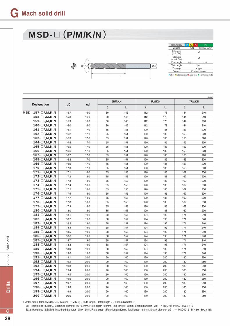
Dri
lls
38
G
GS
olid
dril
l
Mach solid drill
MSD- P/M/K/N
ØD Ød ℓ L
3P,M,K,N 5P,M,K,N 7P,M,K,N
ℓ L ℓ L
15.7
15.8
15.9
16.0
16.1
16.2
16.3
16.4
16.5
16.6
16.7
16.8
16.9
17.0
17.1
17.2
17.3
17.4
17.5
17.6
17.7
17.8
17.9
18.0
18.1
18.2
18.3
18.4
18.5
18.6
18.7
18.8
18.9
19.0
19.1
19.2
19.3
19.4
19.5
19.6
19.7
19.8
19.9
20.0
16.0
16.0
16.0
16.0
17.0
17.0
17.0
17.0
17.0
17.0
17.0
17.0
17.0
17.0
18.0
18.0
18.0
18.0
18.0
18.0
18.0
18.0
18.0
18.0
19.0
19.0
19.0
19.0
19.0
19.0
19.0
19.0
19.0
19.0
20.0
20.0
20.0
20.0
20.0
20.0
20.0
20.0
20.0
20.0
80
80
80
80
85
85
85
85
85
85
85
85
85
85
85
85
85
85
85
85
85
85
85
85
88
88
88
88
88
88
88
88
88
88
90
90
90
90
90
90
90
90
90
90
146
146
146
146
151
151
151
151
151
151
151
151
151
151
153
153
153
153
153
153
153
153
153
153
157
157
157
157
157
157
157
157
157
157
160
160
160
160
160
160
160
160
160
160
112
112
112
112
120
120
120
120
120
120
120
120
120
120
120
120
120
120
120
120
120
120
120
120
124
124
124
124
124
124
124
124
124
124
130
130
130
130
130
130
130
130
130
130
178
178
178
178
186
186
186
186
186
186
186
186
186
186
188
188
188
188
188
188
188
188
188
188
193
193
193
193
193
193
193
193
193
193
200
200
200
200
200
200
200
200
200
200
144
144
144
144
153
153
153
153
153
153
153
153
153
153
162
162
162
162
162
162
162
162
162
162
171
171
171
171
171
171
171
171
171
171
180
180
180
180
180
180
180
180
180
180
210
210
210
210
220
220
220
220
220
220
220
220
220
220
230
230
230
230
230
230
230
230
230
230
240
240
240
240
240
240
240
240
240
240
250
250
250
250
250
250
250
250
250
250
Designation
157- P,M,K,N158- P,M,K,N159- P,M,K,N160- P,M,K,N161- P,M,K,N162- P,M,K,N163- P,M,K,N164- P,M,K,N165- P,M,K,N166- P,M,K,N167- P,M,K,N168- P,M,K,N169- P,M,K,N170- P,M,K,N171- P,M,K,N172- P,M,K,N173- P,M,K,N174- P,M,K,N175- P,M,K,N176- P,M,K,N177- P,M,K,N178- P,M,K,N179- P,M,K,N180- P,M,K,N181- P,M,K,N182- P,M,K,N183- P,M,K,N184- P,M,K,N185- P,M,K,N186- P,M,K,N187- P,M,K,N188- P,M,K,N189- P,M,K,N190- P,M,K,N191- P,M,K,N192- P,M,K,N193- P,M,K,N194- P,M,K,N195- P,M,K,N196- P,M,K,N197- P,M,K,N198- P,M,K,N199 - P,M,K,N200- P,M,K,N
MSD
(mm)
※ Order made items : MSD -Material (P,M,K,N) × Flute length - Total length L × Shank diameter S Ex.1)Workpiece : SM45C, Machined diameter : Ø10.1mm, Flute length : 60mm, Total length : 80mm, Shank diameter : Ø11 MSD101-P × 60 - 80L × 11S Ex.2)Workpiece : STS303, Machined diameter : Ø10.12mm, Flute length : Flute length:60mm, Total length : 80mm, Shank diameter : Ø11 MSD1012 - M × 60 - 80L × 11S
P Steel M Stainless steel K Cast iron N Non-ferrous metal
TerminologyCoating
Point angleTwist angle
ThinningCoolant
Tolerance(drill Dia.)
Tolerance(shank Dia.)
TiAℓN
h7
h6
140°30°
X typeExternal system
Cernented carbide
135°
P M K N
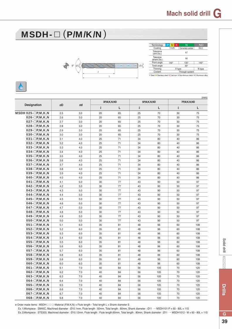
Drills
39
G
GS
olid drill
Mach solid drill
MSDH- P/M/K/N
ØD Ød ℓ L
3P,M,K,N,ND 5P,M,K,N,ND 7P,M,K,N,ND
ℓ L ℓ L
2.5
2.6
2.7
2.8
2.9
3.0
3.1
3.2
3.3
3.4
3.5
3.6
3.7
3.8
3.9
4.0
4.1
4.2
4.3
4.4
4.5
4.6
4.7
4.8
4.9
5.0
5.1
5.2
5.3
5.4
5.5
5.6
5.7
5.8
5.9
6.0
6.1
6.2
6.3
6.4
6.5
6.6
6.7
6.8
3.0
3.0
3.0
3.0
3.0
3.0
4.0
4.0
4.0
4.0
4.0
4.0
4.0
4.0
4.0
4.0
5.0
5.0
5.0
5.0
5.0
5.0
5.0
5.0
5.0
5.0
6.0
6.0
6.0
6.0
6.0
6.0
6.0
6.0
6.0
6.0
7.0
7.0
7.0
7.0
7.0
7.0
7.0
7.0
20
20
20
20
20
20
25
25
25
25
25
25
25
25
25
25
30
30
30
30
30
30
30
30
30
30
35
35
35
35
35
35
35
35
35
35
40
40
40
40
40
40
40
40
65
65
65
65
65
65
71
71
71
71
71
71
71
71
71
71
77
77
77
77
77
77
77
77
77
77
81
81
81
81
81
81
81
81
81
81
84
84
84
84
84
84
84
84
25
25
25
25
25
25
34
34
34
34
34
34
34
34
34
34
43
43
43
43
43
43
43
43
43
43
48
48
48
48
48
48
48
48
48
48
56
56
56
56
56
56
56
56
70
70
70
70
70
70
80
80
80
80
80
80
80
80
80
80
90
90
90
90
90
90
90
90
90
90
96
96
96
96
96
96
96
96
96
96
105
105
105
105
105
105
105
105
30
30
30
30
30
30
40
40
40
40
40
40
40
40
40
40
50
50
50
50
50
50
50
50
50
50
60
60
60
60
60
60
60
60
60
60
70
70
70
70
70
70
70
70
75
75
75
75
75
75
86
86
86
86
86
86
86
86
86
86
97
97
97
97
97
97
97
97
97
97
108
108
108
108
108
108
108
108
108
108
120
120
120
120
120
120
120
120
Designation
MSDH 025- P,M,K,N 026- P,M,K,N 027- P,M,K,N 028- P,M,K,N 029- P,M,K,N 030- P,M,K,N 031- P,M,K,N 032- P,M,K,N 033- P,M,K,N 034- P,M,K,N 035- P,M,K,N 036- P,M,K,N 037- P,M,K,N 038- P,M,K,N 039- P,M,K,N 040- P,M,K,N 041- P,M,K,N 042- P,M,K,N 043- P,M,K,N 044- P,M,K,N 045- P,M,K,N 046- P,M,K,N 047- P,M,K,N 048- P,M,K,N 049- P,M,K,N 050- P,M,K,N 051- P,M,K,N 052- P,M,K,N 053- P,M,K,N 054- P,M,K,N 055- P,M,K,N 056- P,M,K,N 057- P,M,K,N 058- P,M,K,N 059- P,M,K,N 060- P,M,K,N 061- P,M,K,N 062- P,M,K,N 063- P,M,K,N 064- P,M,K,N 065- P,M,K,N 066- P,M,K,N 067- P,M,K,N 068- P,M,K,N
(mm)
※ Order made items : MSDH -Material (P,M,K,N) × Flute length - Total length L × Shank diameter S Ex.1)Workpiece : SM45C, Machined diameter : Ø10.1mm, Flute length : 60mm, Total length : 80mm, Shank diameter : Ø11 MSDH101-P × 60 - 80L × 11S Ex.2)Workpiece : STS303, Machined diameter : Ø10.12mm, Flute length : Flute length:60mm, Total length : 80mm, Shank diameter : Ø11 MSDH1012 - M × 60 - 80L × 11S
P Steel M Stainless steel K Cast iron N Non-ferrous metal ND Aluminum alloy
TerminologyCoating
Point angleTwist angle
ThinningCoolant
Tolerance(drill Dia.)
Tolerance(shank Dia.)
TiAℓN
h7
h6
140°30°
X typeThrough system
Cernented carbide
135° 140°
DLC
N type
P M K N ND
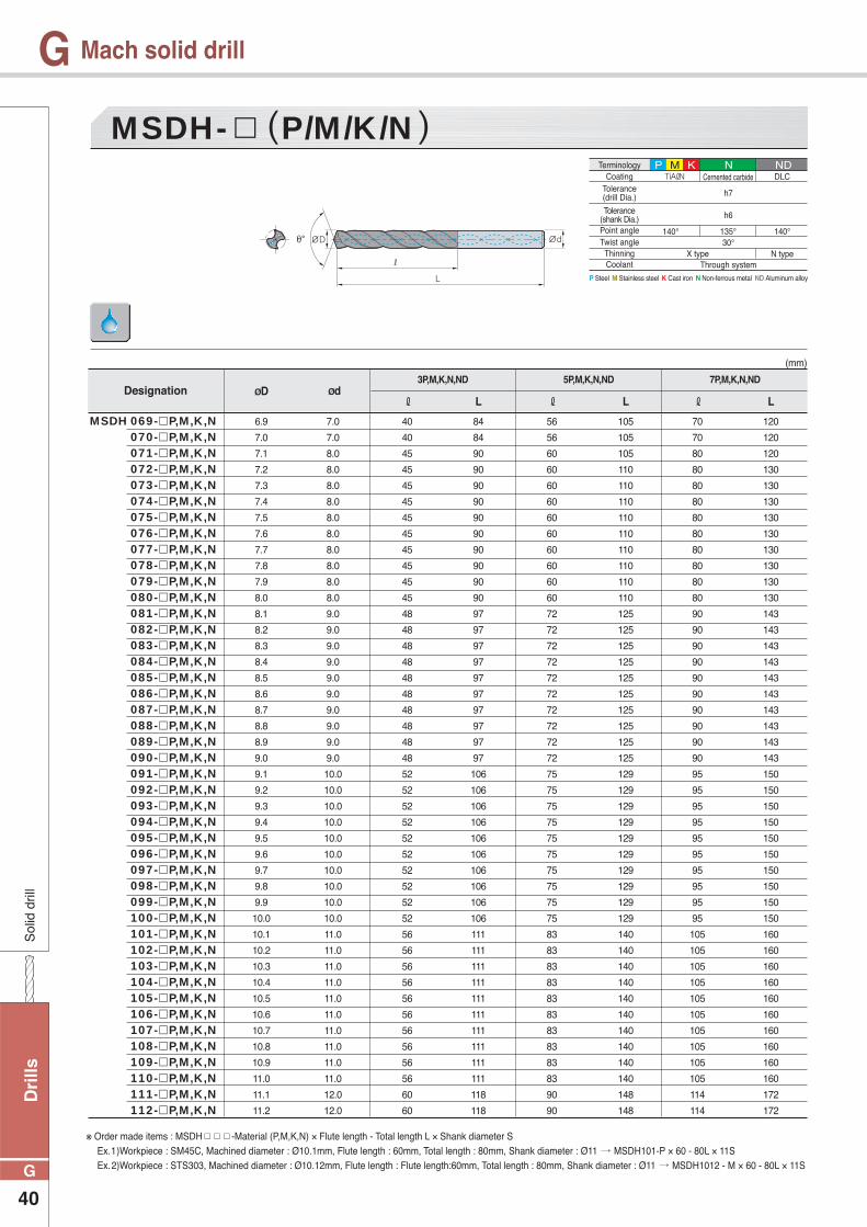
Dri
lls
40
G
GS
olid
dril
l
Mach solid drill
MSDH- P/M/K/N
ØD Ød ℓ L
3P,M,K,N,ND 5P,M,K,N,ND 7P,M,K,N,ND
ℓ L ℓ L
6.9
7.0
7.1
7.2
7.3
7.4
7.5
7.6
7.7
7.8
7.9
8.0
8.1
8.2
8.3
8.4
8.5
8.6
8.7
8.8
8.9
9.0
9.1
9.2
9.3
9.4
9.5
9.6
9.7
9.8
9.9
10.0
10.1
10.2
10.3
10.4
10.5
10.6
10.7
10.8
10.9
11.0
11.1
11.2
7.0
7.0
8.0
8.0
8.0
8.0
8.0
8.0
8.0
8.0
8.0
8.0
9.0
9.0
9.0
9.0
9.0
9.0
9.0
9.0
9.0
9.0
10.0
10.0
10.0
10.0
10.0
10.0
10.0
10.0
10.0
10.0
11.0
11.0
11.0
11.0
11.0
11.0
11.0
11.0
11.0
11.0
12.0
12.0
40
40
45
45
45
45
45
45
45
45
45
45
48
48
48
48
48
48
48
48
48
48
52
52
52
52
52
52
52
52
52
52
56
56
56
56
56
56
56
56
56
56
60
60
84
84
90
90
90
90
90
90
90
90
90
90
97
97
97
97
97
97
97
97
97
97
106
106
106
106
106
106
106
106
106
106
111
111
111
111
111
111
111
111
111
111
118
118
56
56
60
60
60
60
60
60
60
60
60
60
72
72
72
72
72
72
72
72
72
72
75
75
75
75
75
75
75
75
75
75
83
83
83
83
83
83
83
83
83
83
90
90
105
105
105
110
110
110
110
110
110
110
110
110
125
125
125
125
125
125
125
125
125
125
129
129
129
129
129
129
129
129
129
129
140
140
140
140
140
140
140
140
140
140
148
148
70
70
80
80
80
80
80
80
80
80
80
80
90
90
90
90
90
90
90
90
90
90
95
95
95
95
95
95
95
95
95
95
105
105
105
105
105
105
105
105
105
105
114
114
120
120
120
130
130
130
130
130
130
130
130
130
143
143
143
143
143
143
143
143
143
143
150
150
150
150
150
150
150
150
150
150
160
160
160
160
160
160
160
160
160
160
172
172
Designation
MSDH 069- P,M,K,N 070- P,M,K,N 071- P,M,K,N 072- P,M,K,N 073- P,M,K,N 074- P,M,K,N 075- P,M,K,N 076- P,M,K,N 077- P,M,K,N 078- P,M,K,N 079- P,M,K,N 080- P,M,K,N 081- P,M,K,N 082- P,M,K,N 083- P,M,K,N 084- P,M,K,N 085- P,M,K,N 086- P,M,K,N 087- P,M,K,N 088- P,M,K,N 089- P,M,K,N 090- P,M,K,N 091- P,M,K,N 092- P,M,K,N 093- P,M,K,N 094- P,M,K,N 095- P,M,K,N 096- P,M,K,N 097- P,M,K,N 098- P,M,K,N 099- P,M,K,N 100- P,M,K,N 101- P,M,K,N 102- P,M,K,N 103- P,M,K,N 104- P,M,K,N 105- P,M,K,N 106- P,M,K,N 107- P,M,K,N 108- P,M,K,N 109- P,M,K,N 110- P,M,K,N 111- P,M,K,N 112- P,M,K,N
(mm)
※ Order made items : MSDH -Material (P,M,K,N) × Flute length - Total length L × Shank diameter S Ex.1)Workpiece : SM45C, Machined diameter : Ø10.1mm, Flute length : 60mm, Total length : 80mm, Shank diameter : Ø11 MSDH101-P × 60 - 80L × 11S Ex.2)Workpiece : STS303, Machined diameter : Ø10.12mm, Flute length : Flute length:60mm, Total length : 80mm, Shank diameter : Ø11 MSDH1012 - M × 60 - 80L × 11S
P Steel M Stainless steel K Cast iron N Non-ferrous metal ND Aluminum alloy
TerminologyCoating
Point angleTwist angle
ThinningCoolant
Tolerance(drill Dia.)
Tolerance(shank Dia.)
TiAℓN
h7
h6
140°30°
X typeThrough system
Cernented carbide
135° 140°
DLC
N type
P M K N ND
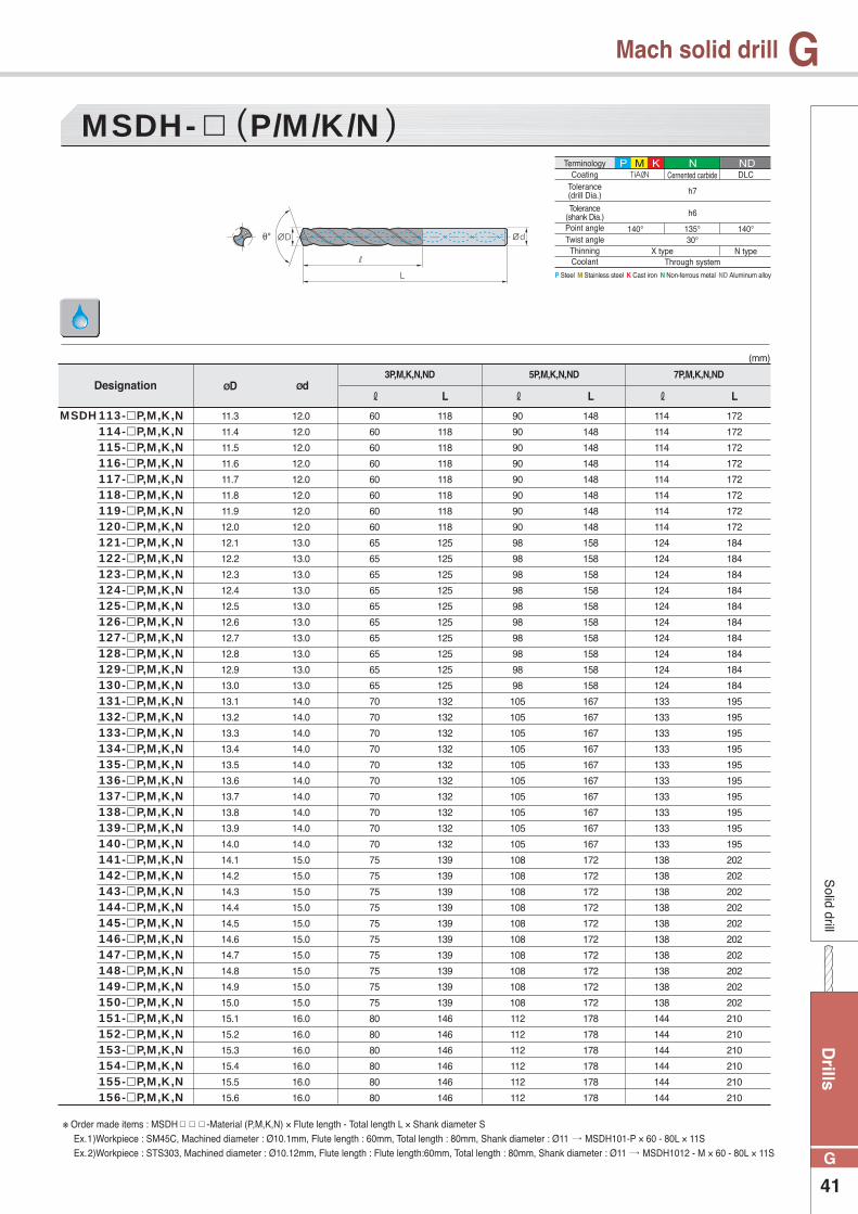
Drills
41
G
GS
olid drill
Mach solid drill
MSDH- P/M/K/N
ØD Ød ℓ L
3P,M,K,N,ND 5P,M,K,N,ND 7P,M,K,N,ND
ℓ L ℓ L
11.3
11.4
11.5
11.6
11.7
11.8
11.9
12.0
12.1
12.2
12.3
12.4
12.5
12.6
12.7
12.8
12.9
13.0
13.1
13.2
13.3
13.4
13.5
13.6
13.7
13.8
13.9
14.0
14.1
14.2
14.3
14.4
14.5
14.6
14.7
14.8
14.9
15.0
15.1
15.2
15.3
15.4
15.5
15.6
12.0
12.0
12.0
12.0
12.0
12.0
12.0
12.0
13.0
13.0
13.0
13.0
13.0
13.0
13.0
13.0
13.0
13.0
14.0
14.0
14.0
14.0
14.0
14.0
14.0
14.0
14.0
14.0
15.0
15.0
15.0
15.0
15.0
15.0
15.0
15.0
15.0
15.0
16.0
16.0
16.0
16.0
16.0
16.0
60
60
60
60
60
60
60
60
65
65
65
65
65
65
65
65
65
65
70
70
70
70
70
70
70
70
70
70
75
75
75
75
75
75
75
75
75
75
80
80
80
80
80
80
118
118
118
118
118
118
118
118
125
125
125
125
125
125
125
125
125
125
132
132
132
132
132
132
132
132
132
132
139
139
139
139
139
139
139
139
139
139
146
146
146
146
146
146
90
90
90
90
90
90
90
90
98
98
98
98
98
98
98
98
98
98
105
105
105
105
105
105
105
105
105
105
108
108
108
108
108
108
108
108
108
108
112
112
112
112
112
112
148
148
148
148
148
148
148
148
158
158
158
158
158
158
158
158
158
158
167
167
167
167
167
167
167
167
167
167
172
172
172
172
172
172
172
172
172
172
178
178
178
178
178
178
114
114
114
114
114
114
114
114
124
124
124
124
124
124
124
124
124
124
133
133
133
133
133
133
133
133
133
133
138
138
138
138
138
138
138
138
138
138
144
144
144
144
144
144
172
172
172
172
172
172
172
172
184
184
184
184
184
184
184
184
184
184
195
195
195
195
195
195
195
195
195
195
202
202
202
202
202
202
202
202
202
202
210
210
210
210
210
210
Designation
113- P,M,K,N114- P,M,K,N115- P,M,K,N116- P,M,K,N117- P,M,K,N118- P,M,K,N119- P,M,K,N120- P,M,K,N121- P,M,K,N122- P,M,K,N123- P,M,K,N124- P,M,K,N125- P,M,K,N126- P,M,K,N127- P,M,K,N128- P,M,K,N129- P,M,K,N130- P,M,K,N131- P,M,K,N132- P,M,K,N133- P,M,K,N134- P,M,K,N135- P,M,K,N136- P,M,K,N137- P,M,K,N138- P,M,K,N139- P,M,K,N140- P,M,K,N141- P,M,K,N142- P,M,K,N143- P,M,K,N144- P,M,K,N145- P,M,K,N146- P,M,K,N147- P,M,K,N148- P,M,K,N149- P,M,K,N150- P,M,K,N151- P,M,K,N152- P,M,K,N153- P,M,K,N154- P,M,K,N155- P,M,K,N156- P,M,K,N
MSDH
(mm)
※ Order made items : MSDH -Material (P,M,K,N) × Flute length - Total length L × Shank diameter S Ex.1)Workpiece : SM45C, Machined diameter : Ø10.1mm, Flute length : 60mm, Total length : 80mm, Shank diameter : Ø11 MSDH101-P × 60 - 80L × 11S Ex.2)Workpiece : STS303, Machined diameter : Ø10.12mm, Flute length : Flute length:60mm, Total length : 80mm, Shank diameter : Ø11 MSDH1012 - M × 60 - 80L × 11S
P Steel M Stainless steel K Cast iron N Non-ferrous metal ND Aluminum alloy
TerminologyCoating
Point angleTwist angle
ThinningCoolant
Tolerance(drill Dia.)
Tolerance(shank Dia.)
TiAℓN
h7
h6
140°30°
X typeThrough system
Cernented carbide
135° 140°
DLC
N type
P M K N ND

Dri
lls
42
G
GS
olid
dril
l
Mach solid drill
MSDH- P/M/K/N
ØD Ød ℓ L
3P,M,K,N,ND 5P,M,K,N,ND 7P,M,K,N,ND
ℓ L ℓ L
15.7
15.8
15.9
16.0
16.1
16.2
16.3
16.4
16.5
16.6
16.7
16.8
16.9
17.0
17.1
17.2
17.3
17.4
17.5
17.6
17.7
17.8
17.9
18.0
18.1
18.2
18.3
18.4
18.5
18.6
18.7
18.8
18.9
19.0
19.1
19.2
19.3
19.4
19.5
19.6
19.7
19.8
19.9
20.0
16.0
16.0
16.0
16.0
17.0
17.0
17.0
17.0
17.0
17.0
17.0
17.0
17.0
17.0
18.0
18.0
18.0
18.0
18.0
18.0
18.0
18.0
18.0
18.0
19.0
19.0
19.0
19.0
19.0
19.0
19.0
19.0
19.0
19.0
20.0
20.0
20.0
20.0
20.0
20.0
20.0
20.0
20.0
20.0
80
80
80
80
85
85
85
85
85
85
85
85
85
85
85
85
85
85
85
85
85
85
85
85
88
88
88
88
88
88
88
88
88
88
90
90
90
90
90
90
90
90
90
90
146
146
146
146
151
151
151
151
151
151
151
151
151
151
153
153
153
153
153
153
153
153
153
153
157
157
157
157
157
157
157
157
157
157
160
160
160
160
160
160
160
160
160
160
112
112
112
112
120
120
120
120
120
120
120
120
120
120
120
120
120
120
120
120
120
120
120
120
124
124
124
124
124
124
124
124
124
124
130
130
130
130
130
130
130
130
130
130
178
178
178
178
186
186
186
186
186
186
186
186
186
186
188
188
188
188
188
188
188
188
188
188
193
193
193
193
193
193
193
193
193
193
200
200
200
200
200
200
200
200
200
200
144
144
144
144
153
153
153
153
153
153
153
153
153
153
162
162
162
162
162
162
162
162
162
162
171
171
171
171
171
171
171
171
171
171
180
180
180
180
180
180
180
180
180
180
210
210
210
210
220
220
220
220
220
220
220
220
220
220
230
230
230
230
230
230
230
230
230
230
240
240
240
240
240
240
240
240
240
240
250
250
250
250
250
250
250
250
250
250
Designation
157- P,M,K,N158- P,M,K,N159- P,M,K,N160- P,M,K,N161- P,M,K,N162- P,M,K,N163- P,M,K,N164- P,M,K,N165- P,M,K,N166- P,M,K,N167- P,M,K,N168- P,M,K,N169- P,M,K,N170- P,M,K,N171- P,M,K,N172- P,M,K,N173- P,M,K,N174- P,M,K,N175- P,M,K,N176- P,M,K,N177- P,M,K,N178- P,M,K,N179- P,M,K,N180- P,M,K,N181- P,M,K,N182- P,M,K,N183- P,M,K,N184- P,M,K,N185- P,M,K,N186- P,M,K,N187- P,M,K,N188- P,M,K,N189- P,M,K,N190- P,M,K,N191- P,M,K,N192- P,M,K,N193- P,M,K,N194- P,M,K,N195- P,M,K,N196- P,M,K,N197- P,M,K,N198- P,M,K,N199 - P,M,K,N200- P,M,K,N
MSDH
(mm)
※ Order made items : MSDH -Material (P,M,K,N) × Flute length - Total length L × Shank diameter S Ex.1)Workpiece : SM45C, Machined diameter : Ø10.1mm, Flute length : 60mm, Total length : 80mm, Shank diameter : Ø11 MSDH101-P × 60 - 80L × 11S Ex.2)Workpiece : STS303, Machined diameter : Ø10.12mm, Flute length : Flute length:60mm, Total length : 80mm, Shank diameter : Ø11 MSDH1012 - M × 60 - 80L × 11S
P Steel M Stainless steel K Cast iron N Non-ferrous metal ND Aluminum alloy
TerminologyCoating
Point angleTwist angle
ThinningCoolant
Tolerance(drill Dia.)
Tolerance(shank Dia.)
TiAℓN
h7
h6
140°30°
X typeThrough system
Cernented carbide
135° 140°
DLC
N type
P M K N ND
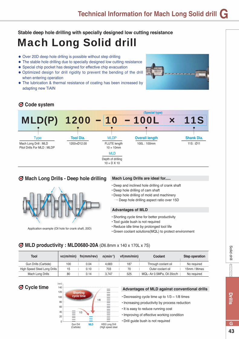
Drills
43
G
GS
olid drill
Technical Information for Mach Long Solid drill
Type Tool Dia. MLDP
MLD
Overall length Shank Dia.FLUTE length
10 = 10mm
Depth of drilling10 = D X 10
100L : 100mm 11S : Ø11Mach Long Drill : MLDPilot Drills For MLD : MLDP
1200=Ø12.00
MLD(P) 10 100L × 11S1200
Code system
Mach Long Drills - Deep hole drilling
MLD productivity : MLD0680-20A (Ø6.8mm x 140 x 170L x 7S)
Cycle time
• Deep and inclined hole drilling of crank shaft• Deep hole drilling of cam shaft• Deep hole drilling of mold and machinery
Deep hole drilling aspect ratio over 15D
• Shorting cycle time for better productivity• Tool guide bush is not required• Reduce idle time by prolonged tool life• Green coolant solutions(MQL) to protect environment
• Decreasing cycle time up to 1/3 ~ 1/8 times
• Increasing productivity by process reduction
• It is easy to reduce running cost
• Improving of effective working condition
• Drill guide bush is not required
Mach Long Drills are ideal for.....
Advantages of MLD against conventional drills
Advantages of MLD
Application example (Oil hole for crank shaft, 20D)
Tool
Gun Drills (Carbide)
High Speed Steel Long Drills
Mach Long Drills
Through coolant oil
Outer coolant oil
MQL- Air 0.5MPa, Oil 20cc/h
No required
15mm / 9times
No required
100
15
80
0.04
0.10
0.14
4,683
703
3,747
187
70
525
vc(m/min) fn(mm/rev) n(min-1) vf(mm/min) Coolant Step operation
MLD HSS Long Drill(High speed steel
Gun Dril(Carbide)
0
20
40
60
80
100
120
140
(min)
1/3
1/8
Shorting cycle time
Mach Long Solid drillStable deep hole drilling with specially designed low cutting resistance
● Over 20D deep hole drlling is possible without step drilling ● The stable hole drilling due to specially designed low cutting resistance ● Special chip pocket has designed for effective chip evacuation ● Optimized design for drill rigidity to prevent the bending of the drill
when entering operation ● The lubrication & thermal resistance of coating has been increased by
adapting new TiAlN
(Special type)

Dri
lls
44
G
G
To make the optimal of MLD
Sol
id d
rill
Technical Information for Mach Long Solid drill
Function of MLD & MLDP
Application example
Relationship of point angle between MLD & MLDP
Large point angle of Pliot Drill : Stable condition Small point angle of Pliot Drill : Unstable condition
Point angle of MLD < Point angle of
foundation hole
Stable machining
Point angle of MLD > Point angle of
foundation hole
Chipping on the drill edge
MLD MLD
Foundation hole
(MLDP machining)
3rd
2nd
1st
Chipping on the drill edge1st. Pliot drilling
• vc(m/min) = Normal • fn(mm/rev) = Normal
2nd. Deep drilling by MLD
Approach the drill 1mm less than the depth of MLDP drilling.
• vc(m/min) = 15
• fn(mm/rev) = 0.5
2nd MLD drilling (Machining stage)
• vc(m/min) = Normal
• fn(mm/rev) = Normal
3rd MLD drilling (Piercing stage)
• vc(m/min) = Normal
• fn(mm/rev) = Normal feed / 2
MLD
MLD
MLD
Cutting condition
Cutting condition
Workpiece
Workpiece
Machine
Machine
Tool life
Tool life
Designation
Designation
MLD0600-22A (Ø6mm, Aspect ratio 18D)
MLD0400-25A (Ø4mm, Aspect ratio 16D)
vc(m/min) =70 fn(mm/rev)=0.18 MQL(30cc/hour)Air(MPa)=0.7
vc(m/min) = 63 fn(mm/rev)= 0.1
Part of automobile (SCM440, HB255~330)
Part of automobile (GC250)
Horizontal milling machine
Rotary milling machine
1000 holes, 105m
4400 holes, 207m

Drills
45
G
GSolid drill
Mach Long drill
3.0
4.0
5.0
6.0
7.0
8.0
9.0
10.0
3.0
4.0
5.0
6.0
7.0
8.0
9.0
10.0
3.0
4.0
5.0
6.0
7.0
8.0
9.0
10.0
3.0
4.0
5.0
6.0
7.0
8.0
9.0
10.0
25
34
43
48
56
60
72
75
60
80
100
120
140
160
180
200
70
80
90
96
105
110
125
129
110
130
150
170
190
210
230
250
30
40
50
60
70
80
90
95
75
100
125
150
175
200
-
-
75
86
97
108
120
130
143
150
120
150
175
200
225
250
-
-
0300-
0400-
0500-
0600-
0700-
0800-
0900-
1000-
0300-
0400-
0500-
0600-
0700-
0800-
0900-
1000-
MLDP(Mach long Drills)
MLD(Mach long Drills)
(mm)
(mm)
Designation
Designation
ØD
ØD
Ød
Ød
ℓ
ℓ
ℓ
ℓ
L
L
5 (ℓ / ØD = 5)
5 (ℓ / ØD = 5)
5 (ℓ / ØD = 7)
5 (ℓ / ØD = 7)
L
L
MLDP
MLD
Pilot Drills with oil hole for MLD
Mach long drills with oil hole for deep hole machining
Coating
Tolerance(drill Dia.)
Twist angle
Tolerance
Point angle
Thinning
Coolant
Coating
Tolerance(drill Dia.)
Twist angle
Tolerance
Point angle
Thinning
Coolant
TiAIN
×6
30°
h6
150°
X type
Through system
TiAIN
h7
30°
h6
140°
X type
Through system
Order made items : MLDP���� × Flute length - Total length L × Shank diameter S Ex.1) Machined diameter : Ø5.8mm, Flute length : 50mm, Total length : 100mm, MLDP0580 × 50-100L × 6S
Order made items : MLD����-Aspect ratio Ex.1) Machined diameter : Ø5.3mm, Flute length : 120mm, Total length : 180mm MLD0530-22(Aspect ratio)
Drill Dia. (ØD)Over
-
3
6
10
14
18
3
6
10
14
18
24
0 ~ – 0.006
0 ~ – 0.008
0 ~ – 0.009
0 ~ – 0.011
0 ~ – 0.011
0 ~ – 0.013
0 ~ – 0.010
0 ~ – 0.012
0 ~ – 0.015
0 ~ – 0.018
0 ~ – 0.018
0 ~ – 0.021
+ 0.020 ~ + 0.026
+ 0.028 ~ + 0.036
+ 0.034 ~ + 0.043
+ 0.040 ~ + 0.051
+ 0.045 ~ + 0.056
+ 0.054 ~ + 0.067
Underh6 h7 x6
Tolerance code
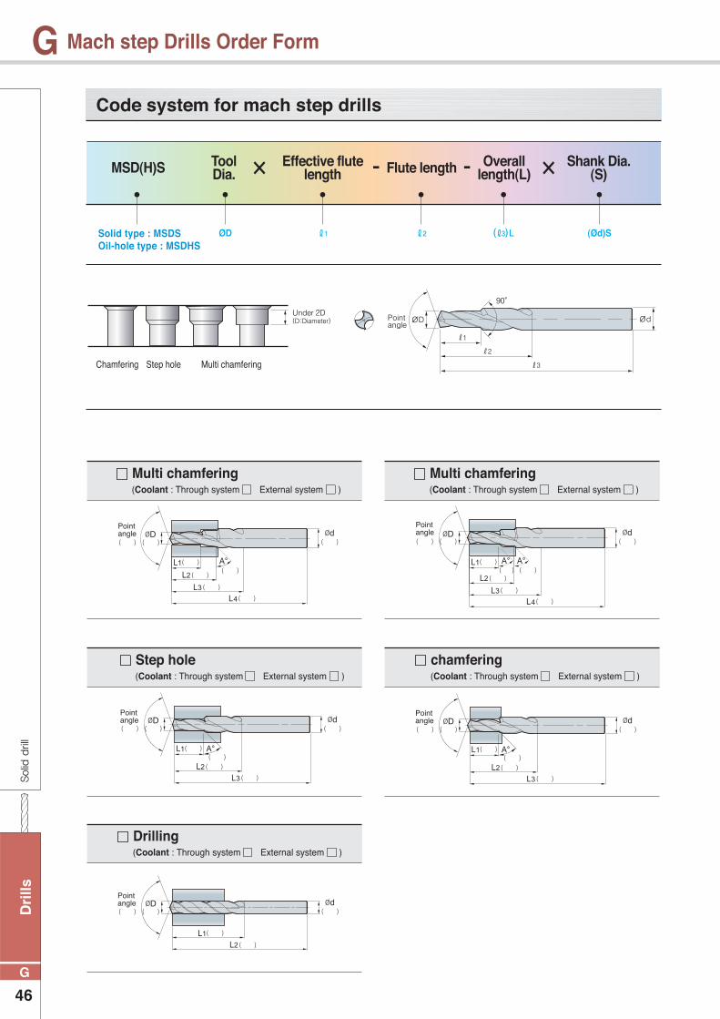
Dri
lls
46
G
GSolid drill
Mach step Drills Order Form
Solid type : MSDSOil-hole type : MSDHS
ØD ℓ1 ℓ2 (ℓ3) L (Ød)S
Code system for mach step drills
MSD(H)S Tool Dia. × ×Effective flute
length Flute length Overall length(L)
Shank Dia.(S)
Chamfering Step hole Multi chamfering
- -
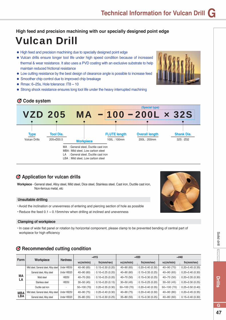
Drills
47
G
GS
olid drill
Technical Information for Vulcan Drill
40~90 (65)
40~90 (60)
40~70 (50)
30~50 (45)
50~100 (70)
40~90 (75)
35~80 (55)
0.15~0.30 (0.20)
0.10~0.25 (0.20)
0.10~0.25 (0.20)
0.10~0.20 (0.15)
0.20~0.35 (0.30)
0.20~0.40 (0.30)
0.15~0.30 (0.25)
0.20~0.40 (0.30)
0.15~0.35 (0.25)
0.15~0.30 (0.25)
0.15~0.25 (0.20)
0.20~0.40 (0.35)
0.20~0.40 (0.30)
0.15~0.30 (0.25)
0.20~0.45 (0.35)
0.20~0.40 (0.30)
0.20~0.35 (0.30)
0.20~0.30 (0.25)
0.25~0.50 (0.40)
0.20~0.45 (0.35)
0.15~0.40 (0.30)
40~90 (65)
40~90 (60)
40~70 (50)
30~50 (45)
50~100 (70)
40~90 (75)
35~80 (55)
40~90 (70)
40~90 (65)
40~70 (50)
30~50 (45)
50~100 (70)
40~90 (80)
40~80 (60)
MALA
MBALBA
Mild steel, General steel, Alloy steel
General steel, Alloy steel
Mold steel
Stainless steel
Ductile cast iron
Mild steel, General steel, Alloy steel
General steel, Alloy steel
Under HB250
Under HB320
HB250
HB250
-
Under HB250
Under HB320
Type Tool Dia.
Workpiece
FLUTE length Overall length Shank Dia.
MA : General steel, Ductile cast ironMBA : Mild steel, Low carbon steelLA : General steel, Ductile cast ironLBA : Mild steel, Low carbon steel
100L : 100mm 200L : 200mm 32S : Ø32Vulcan Drills 205=Ø20.5
VZD MA 100 200L × 32S205
Code system
Application for vulcan drills
Recommended cutting condition
Workpiece - General steel, Alloy steel, Mild steel, Dice steel, Stainless steel, Cast iron, Ductile cast iron, Non-ferrous metal, etc
Form Workpiece Hardness ~Ø15
fn(mm/rev)vc(m/min)
~Ø20
fn(mm/rev)vc(m/min)
~Ø40
fn(mm/rev)vc(m/min)
• Avoid the inclination or unevenness of entering and piercing section of hole as possible
• Reduce the feed 0.1 ~ 0.15mm/rev when drilling at inclined and unevenness
• In case of wide flat panel or rotation by horizontal component, please clamp to be prevented bending of central part of workpiece for high efficiency
Unsuitable drilling
Clamping of workpiece
Vulcan DrillHigh feed and precision machining with our specially designed point edge
● High feed and precision machining due to specially designed point edge ● Vulcan drills ensure longer tool life under high speed condition because of increased
thermal & wear resistance. It also uses a PVD coating with an exclusive substrate to help maintain reduced frictional resistance
● Low cutting resistance by the best design of clearance angle is possible to increase feed ● Smoother chip control due to improved chip breakage ● Rmax: 6~25s, Hole tolerance: IT8 ~ 10 ● Strong shock resistance ensures long tool life under the heavy interrupted machining
(Special type)

Dri
lls
48
G
GS
olid
dril
l
Vulcan Drill
12.6~13.5
13.6~14.5
14.6~15.5
15.6~16.5
16.6~17.5
17.6~18.5
18.6~19.5
19.6~20.5
20.6~21.5
21.6~22.5
22.6~23.5
23.6~24.5
24.6~25.5
25.6~26.5
26.6~27.5
27.6~28.5
28.6~29.5
29.6~30.5
30.6~31.5
31.6~32.5
32.6~33.5
33.6~34.5
34.6~35.5
35.6~36.5
36.6~37.5
37.6~38.5
38.6~39.5
39.6~40.5
16
16
20
20
20
20
25
25
25
25
25
32
32
32
32
32
32
32
40
40
40
40
40
40
40
40
40
40
110
115
125
130
135
140
155
155
155
160
160
170
170
175
175
180
185
185
205
210
215
220
225
225
230
235
240
245
62
67
75
80
85
90
99
99
99
104
104
110
110
115
115
120
125
125
135
140
145
150
155
155
160
165
170
175
48
48
50
50
50
50
56
56
56
56
56
60
60
60
60
60
60
60
70
70
70
70
70
70
70
70
70
70
44
48
55
59
63
66
74
73
72
76
74
79
78
82
80
84
88
87
95
98
101
104
107
110
113
116
119
122
126~135MA, MBA
136~145MA, MBA
146~155MA, MBA
156~165MA, MBA
166~175MA, MBA
176~185MA, MBA
186~195MA, MBA
196~205MA, MBA
206~215MA, MBA
216~225MA, MBA
226~235MA, MBA
236~245MA, MBA
246~255MA, MBA
256~265MA, MBA
266~275MA, MBA
276~285MA, MBA
286~295MA, MBA
296~305MA, MBA
306~315MA, MBA
316~325MA, MBA
326~335MA, MBA
336~345MA, MBA
346~355MA, MBA
356~365MA, MBA
366~375MA, MBA
376~385MA, MBA
386~395MA, MBA
396~405MA, MBA
Vulcan Drill(VZD)-MA, MBA
(mm)
Designation ØD Ød ℓ2ℓ1 ℓ3L
VZD
Type
Coating
Tolerance(drill Dia.)
Tolerance(shank Dia.)
Point angle
Twist angle
Thinning
Coolant
TiN
h7
h7
X type
Through system
MA
140°
25°
MBA
150°
20°
VZD���MA : For General steel, Ductile cast iron MBA : For Mild steel, Low carbon steel
Order made items : VZD���M� × Flute length - Total length L
Ex.1) MA Type, Machined diameter : Ø18.6mm, Flute length : 110mm, Total length : 200mm --- VZD186MA × 110-200L
Ex.2) MAType, Machined diameter : Ø18.63, Flute length : 110mm, Total length : 200mm --- VZD1863MA × 110-200L
Ex.3) MAType, Machined diameter : Ø18.6, Standard --- VZD186MA

Drills
49
G
GS
olid drill
Vulcan Drill
12.6~13.5
13.6~14.5
14.6~15.5
15.6~16.5
16.6~17.5
17.6~18.5
18.6~19.5
19.6~20.5
20.6~21.5
21.6~22.5
22.6~23.5
23.6~24.5
24.6~25.5
25.6~26.5
26.6~27.5
27.6~28.5
28.6~29.5
29.6~30.5
30.6~31.5
31.6~32.5
32.6~33.5
33.6~34.5
34.6~35.5
35.6~36.5
36.6~37.5
37.6~38.5
38.6~39.5
39.6~40.5
16
16
20
20
20
20
25
25
25
25
25
32
32
32
32
32
32
32
40
40
40
40
40
40
40
40
40
40
140
145
155
165
170
175
190
195
195
200
210
220
225
230
235
240
245
255
275
280
280
290
295
300
305
315
320
325
92
97
105
115
120
125
134
139
139
144
154
160
165
170
175
180
185
195
205
210
215
220
225
230
235
245
250
255
48
48
50
50
50
50
56
56
56
56
56
60
60
60
60
60
60
60
70
70
70
70
70
70
70
70
70
70
74
78
85
94
98
101
109
113
112
116
124
129
133
137
141
144
148
157
166
172
173
177
181
183
188
193
198
203
126~135LA, LBA
136~145LA, LBA
146~155LA, LBA
156~165LA, LBA
166~175LA, LBA
176~185LA, LBA
186~195LA, LBA
196~205LA, LBA
206~215LA, LBA
216~225LA, LBA
226~235LA, LBA
236~245LA, LBA
246~255LA, LBA
256~265LA, LBA
266~275LA, LBA
276~285LA, LBA
286~295LA, LBA
296~305LA, LBA
306~315LA, LBA
316~325LA, LBA
326~335LA, LBA
336~345LA, LBA
346~355LA, LBA
356~365LA, LBA
366~375LA, LBA
376~385LA, LBA
386~395LA, LBA
396~405LA, LBA
Vulcan Drill(VZD) - LA, LBA
(mm)
Designation ØD Ød ℓ2ℓ1 ℓ3L
VZD
Type
Coating
Tolerance(drill Dia.)
Tolerance(shank Dia.)
Point angle
Twist angle
Thinning
Coolant
TiN
h7
h7
X type
Through system
LA
140°
25°
LBA
150°
20°
VZD���LA : For General steel, Ductile cast iron LBA : For Mild steel, Low carbon steel
Order made items : VZD���L� × Flute length - Total length L
Ex.1) LA Type, Machined diameter : Ø18.6mm, Flute length : 110mm, Total length : 200mm --- VZD186LA × 110-200L
Ex.2) LAType, Machined diameter : Ø18.63, Flute length : 110mm, Total length : 200mm --- VZD1863LA × 110-200L
Ex.3) LAType, Machined diameter : Ø18.6, Standard --- VZD186LA
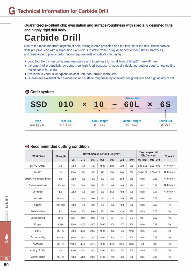
Dri
lls
50
G
G
50
70
100
150~180
100
40~110
200~300
200
65Hs
60~80
80~120
60~120
60~120
40
90~120
2900
2300
2200
700
2200
700
2000
2400
350
6000
5000
3500
16000
8000
8000
1600
1530
1500
340
1200
340
1500
1500
200
4000
3500
2500
8500
4500
5400
1100
1050
1000
250
800
260
800
900
150
2500
2000
1800
5700
2800
2800
1000
920
900
190
652
190
600
650
100
2000
1500
1500
4500
2100
2100
800
765
750
160
550
170
450
500
80
1400
1400
1200
3700
1750
1750
700
640
650
140
460
150
400
420
70
1000
1200
1000
3100
1050
1050
600
560
550
120
380
120
350
380
55
800
1000
900
2800
700
200
0.03~0.06
0.03~0.06
0.03
0.02
0.03
0.04
0.03
0.03
0.01
0.06
0.05
0.04
0.1
0.05
0.05
0.03~0.06
0.06~0.12
0.06
0.04
0.06
0.08
0.06
0.06
0.02
0.12
0.10
0.08
0.2
0.15
0.15
SM10C~SM45C
SM55C
SM55C·Pre-hardened steel
Pre-hardened steel
Cr-Ni steel
Mn-steel
Casting
Malleable iron
Chilled casting
Copper
Brass
Bronze casting
Aluminum
Al alloy (Si13%)
Synthetic resin
Cutting oil
Cutting oil
Cutting oil
Cutting oil
Cutting oil
Dry
Dry
Dry
Dry
Dry
Dry
Dry
Dry
Dry
Dry
Sol
id d
rill
Technical Information for Carbide Drill
One of the most important aspects of hole-drilling is hole precision and the tool life of the drill. These carbidedrills are produced with a super fine exclusive substrate from Korloy designed to meet stress, hardness,and resistance to plastic deformation requirements of today's machining
● Long tool life by improving wear resistance and toughness for small hole drilling(Ø1mm~ Ø4mm) ● Increment of productivity by come true high feed because of specially designed cutting edge to low cutting
resistance.(Ø4~ Ø15) ● Available to various workpiece as cast iron, non-ferrous metal, etc. ● Guarantees excellent chip evacuation and surface roughness by specially designed flute and high rigidity of drill
Guaranteed excellent chip evacuation and surface roughness with specially designed fluteand highly rigid drill body
Type Tool Dia. FLUTE length Overall length Shank Dia.10 : 10mm 60L : 60mm 6S : Ø6.0Solid Spiral Drill 010=Ø1.0
SSD × 10 60L × 6S010
Code system
Recommended cutting condition
Workpiece StrengthRevolution as per drill Dia.(min-1)
Ø5 Ø10 Ø15 Ø20 Ø25 Ø30 Ø40 Ø5~Ø12 Ø15~Ø40
Feed as per drill Dia.(mm/rev) Coolant
Carbide Drill
(Special type)
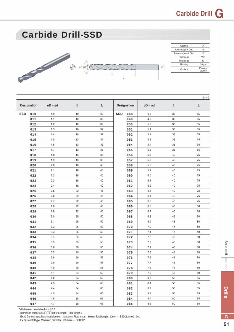
Drills
51
G
GS
olid drill
Carbide Drill
10
10
10
10
10
13
13
13
13
13
18
18
18
18
18
22
22
22
22
22
25
25
25
25
25
25
30
30
30
30
30
34
34
34
34
34
38
38
38
38
38
38
38
38
38
38
40
40
40
40
40
40
40
40
40
40
46
46
46
46
46
46
46
46
46
46
46
46
46
46
50
50
50
50
50
50
1.0
1.1
1.2
1.3
1.4
1.5
1.6
1.7
1.8
1.9
2.0
2.1
2.2
2.3
2.4
2.5
2.6
2.7
2.8
2.9
3.0
3.1
3.2
3.3
3.4
3.5
3.6
3.7
3.8
3.9
4.0
4.1
4.2
4.3
4.4
4.5
4.6
4.7
4.8
4.9
5.0
5.1
5.2
5.3
5.4
5.5
5.6
5.7
5.8
5.9
6.0
6.1
6.2
6.3
6.4
6.5
6.6
6.7
6.8
6.9
7.0
7.1
7.2
7.3
7.4
7.5
7.6
7.7
7.8
7.9
8.0
8.1
8.2
8.3
8.4
8.5
32
32
32
32
32
35
35
35
35
35
40
40
40
40
40
45
45
45
45
45
50
50
50
50
50
50
55
55
55
55
55
60
60
60
60
60
65
65
65
65
65
65
65
65
65
65
75
75
75
75
75
75
75
75
75
75
80
80
80
80
80
80
80
80
80
80
80
80
80
80
85
85
85
85
85
85
010
011
012
013
014
015
016
017
018
019
020
021
022
023
024
025
026
027
028
029
030
031
032
033
034
035
036
037
038
039
040
041
042
043
044
045
046
047
048
049
050
051
052
053
054
055
056
057
058
059
060
061
062
063
064
065
066
067
068
069
070
071
072
073
074
075
076
077
078
079
080
081
082
083
084
085
Carbide Drill-SSD
(mm)
Designation Designationℓ ℓØD = Ød ØD = ØdL L
SSD SSD
Coating
Tolerance(drill Dia.)
Tolerance(shank Dia.)
Point angle
Twist angle
Thinning
Coolant
h8
h7
118˚
30˚
S type
External system
Drill diameter : Available from Ø0.6 Order made items : SSD��� × Flute length - Total length L Ex.1) Genetal type, Machined diameter : Ø8.2mm, Flute length : 60mm, Total length : 90mm --- SSD082 × 60 - 90L Ex.2) Genetal type, Machined diameter : Ø8.2mm --- SSD082

Dri
lls
52
G
GS
olid
dril
l
Carbide Drill
50
50
50
50
50
50
50
50
50
50
50
50
50
50
50
60
60
65
65
65
65
70
8.6
8.7
8.8
8.9
9.0
9.1
9.2
9.3
9.4
9.5
9.6
9.7
9.8
9.9
10.0
10.5
11.0
11.5
12.0
12.5
13.0
15.0
95
95
95
95
95
95
95
95
95
95
100
100
100
100
100
120
120
125
125
125
125
130
086
087
088
089
090
091
092
093
094
095
096
097
098
099
100
105
110
115
120
125
130
150
Carbide Drill-SSD
(mm)
Designation Designationℓ ℓL L
SSD SSD
ØD = Ød ØD = Ød
Coating
Tolerance(drill Dia.)
Tolerance(shank Dia.)
Point angle
Twist angle
Thinning
Coolant
h8
h7
118˚
30˚
S type
External system
Drill diameter : Available from Ø0.6 Order made items : SSD��� × Flute length - Total length L Ex.1) Genetal type, Machined diameter : Ø8.2mm, Flute length : 60mm, Total length : 90mm --- SSD082 × 60 - 90L Ex.2) Genetal type, Machined diameter : Ø8.2mm --- SSD082
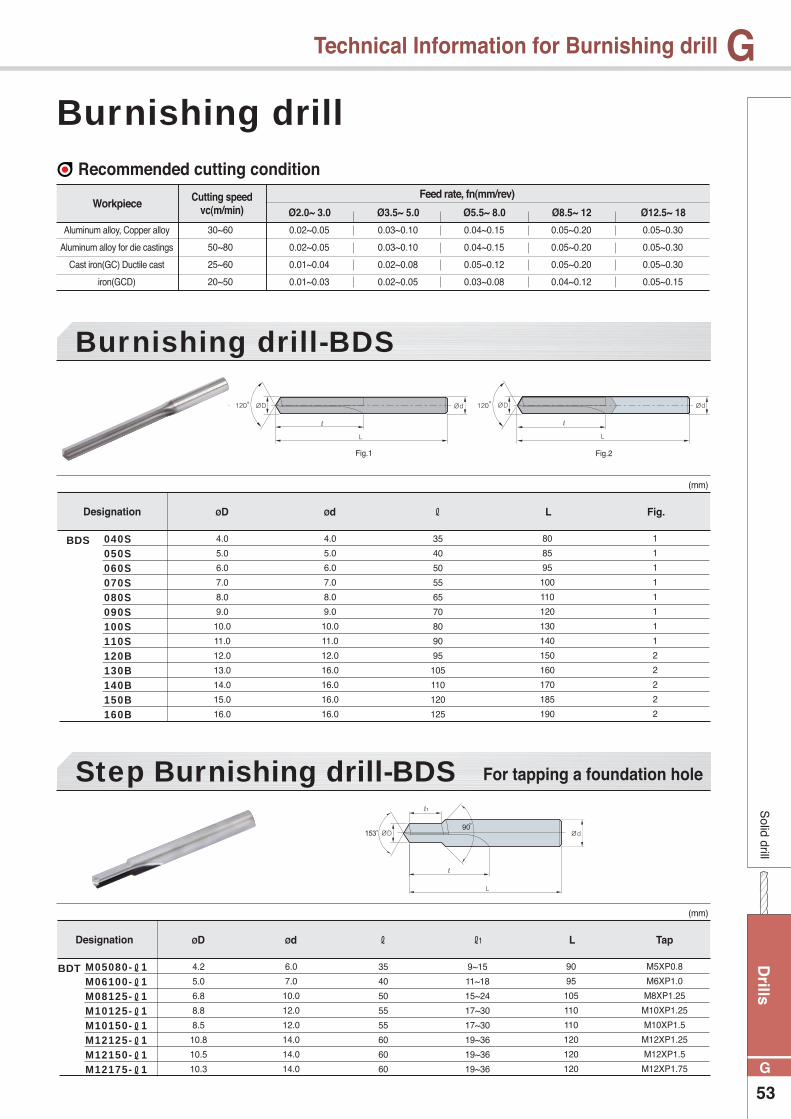
Drills
53
G
GS
olid drill
Technical Information for Burnishing drill
35
40
50
55
65
70
80
90
95
105
110
120
125
9~15
11~18
15~24
17~30
17~30
19~36
19~36
19~36
35
40
50
55
55
60
60
60
4.0
5.0
6.0
7.0
8.0
9.0
10.0
11.0
12.0
13.0
14.0
15.0
16.0
4.2
5.0
6.8
8.8
8.5
10.8
10.5
10.3
4.0
5.0
6.0
7.0
8.0
9.0
10.0
11.0
12.0
16.0
16.0
16.0
16.0
6.0
7.0
10.0
12.0
12.0
14.0
14.0
14.0
80
85
95
100
110
120
130
140
150
160
170
185
190
90
95
105
110
110
120
120
120
M5XP0.8
M6XP1.0
M8XP1.25
M10XP1.25
M10XP1.5
M12XP1.25
M12XP1.5
M12XP1.75
1
1
1
1
1
1
1
1
2
2
2
2
2
040S050S060S070S080S090S100S110S120B130B140B150B160B
M05080-ℓ1M06100-ℓ1M08125-ℓ1M10125-ℓ1M10150-ℓ1M12125-ℓ1M12150-ℓ1M12175-ℓ1
Burnishing drill-BDS
Step Burnishing drill-BDS
(mm)
(mm)
Designation
Designation
ℓ
ℓ1ℓ
ØD
ØD
Ød
Ød
L
L Tap
Fig.
BDS
BDT
Burnishing drillRecommended cutting condition
Fig.1 Fig.2
0.02~0.05
0.02~0.05
0.01~0.04
0.01~0.03
0.03~0.10
0.03~0.10
0.02~0.08
0.02~0.05
0.04~0.15
0.04~0.15
0.05~0.12
0.03~0.08
0.05~0.20
0.05~0.20
0.05~0.20
0.04~0.12
0.05~0.30
0.05~0.30
0.05~0.30
0.05~0.15
Aluminum alloy, Copper alloy
Aluminum alloy for die castings
Cast iron(GC) Ductile cast
iron(GCD)
30~60
50~80
25~60
20~50
Workpiece Cutting speedvc(m/min) Ø2.0~ 3.0 Ø3.5~ 5.0 Ø5.5~ 8.0 Ø8.5~ 12 Ø12.5~ 18
Feed rate, fn(mm/rev)
For tapping a foundation hole
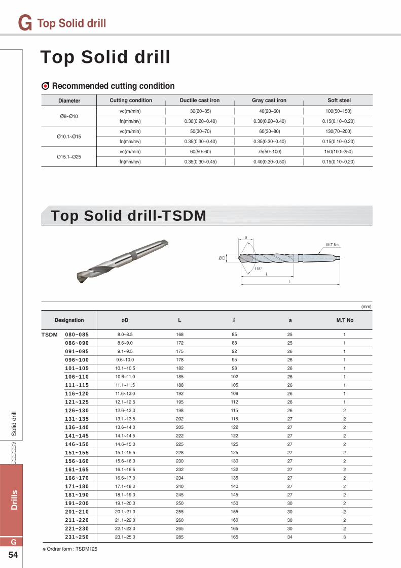
Dri
lls
54
G
GS
olid
dril
l
Top Solid drill
85
88
92
95
98
102
105
108
112
115
118
122
122
125
125
130
132
135
140
145
150
155
160
165
165
8.0~8.5
8.6~9.0
9.1~9.5
9.6~10.0
10.1~10.5
10.6~11.0
11.1~11.5
11.6~12.0
12.1~12.5
12.6~13.0
13.1~13.5
13.6~14.0
14.1~14.5
14.6~15.0
15.1~15.5
15.6~16.0
16.1~16.5
16.6~17.0
17.1~18.0
18.1~19.0
19.1~20.0
20.1~21.0
21.1~22.0
22.1~23.0
23.1~25.0
168
172
175
178
182
185
188
192
195
198
202
205
222
225
228
230
232
234
240
245
250
255
260
265
285
25
25
26
26
26
26
26
26
26
26
27
27
27
27
27
27
27
27
27
27
30
30
30
30
34
1
1
1
1
1
1
1
1
1
2
2
2
2
2
2
2
2
2
2
2
2
2
2
2
3
080~085
086~090
091~095
096~100
101~105
106~110
111~115
116~120
121~125
126~130
131~135
136~140
141~145
146~150
151~155
156~160
161~165
166~170
171~180
181~190
191~200
201~210
211~220
221~230
231~250
Top Solid drill-TSDM
(mm)
Designation ℓØD L a M.T No
TSDM
Top Solid drillRecommended cutting condition
Diameter
Ø8~Ø10
Ø10.1~Ø15
Ø15.1~Ø25
vc(m/min)
fn(mm/rev)
vc(m/min)
fn(mm/rev)
vc(m/min)
fn(mm/rev)
30(20~35)
0.30(0.20~0.40)
50(30~70)
0.35(0.30~0.40)
60(50~60)
0.35(0.30~0.45)
40(20~60)
0.30(0.20~0.40)
60(30~80)
0.35(0.30~0.40)
75(50~100)
0.40(0.30~0.50)
100(50~150)
0.15(0.10~0.20)
130(70~200)
0.15(0.10~0.20)
150(100~250)
0.15(0.10~0.20)
Cutting condition Gray cast ironDuctile cast iron Soft steel
※ Ordrer form : TSDM125

Drills
55
G
GS
olid drill
PCD drill
30
30
30
40
40
45
45
50
50
55
55
60
60
65
65
5.0
5.5
6.0
6.5
7.0
7.5
8.0
8.5
9.0
9.5
10.0
10.5
11.0
11.5
12.0
80
80
80
95
95
100
100
110
110
115
115
120
120
125
125
5.0
5.5
6.0
6.5
7.0
7.5
8.0
8.5
9.0
9.5
10.0
10.5
11.0
11.5
12.0
0500
0550
0600
0650
0700
0750
0800
0850
0900
0950
1000
1050
1100
1150
1200
PDD
(mm)
Designation ℓØD LØd
PDD
PCD drill
PCD Drill Diameter065 : Ø6.5
PDD 065
Code system
Recommended cutting conditionWorkpiece
50 ~ 2500.05 ~ 0.200.10 ~ 0.40
Aluminum alloy
vc(m/min) fn(mm/rev)
● High accuracy hole machining for aluminum alloy
● Drilling tolerance : IT7~8class
● Recommendation with high accuracy and high spindle machine
High accuracy hole machining for aluminum alloy

Dri
lls
56
G
GS
olid
dril
l
Technical Information for Gun Dril
Gun Drill ● High efficiency in deep hole machining
● High accuracy (Hole tolerance : IT9, surface finish : Ra0.1~3.0S)
● Stable Quality due to unique cutting edge and guide pad available regrinding
● Used drill can recycle as change part of carbide
● Depending on request, The drills can change geometry of cutting edge and drive specification
● For ordering, please check length of drill
Stable performance and hole quality with our unique cutting edge and guide padAvailable regrinding
KORLOY Gun Drill Lib type Drill Dia. Length of Drill Drive No.Ø12.05 1500mm D30S : Single
T : Twin
KGD 12.05 1500 / D30S
Code system
Application of Gun Drill on exclusive machine
• Refer to the code system and the above drawing when ordering.
• Refer to the page 90 for the size of a driver.
• The guide bush is necessary for centering before gun-drilling.
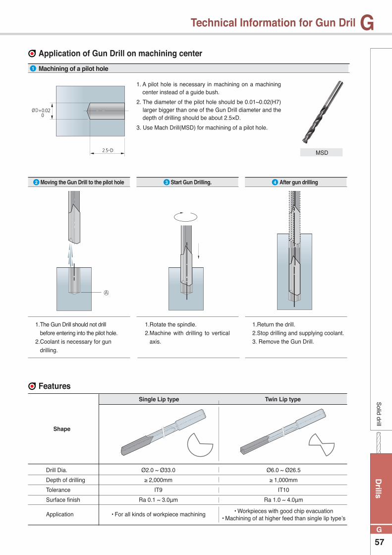
Drills
57
G
G
Ø2.0 ~ Ø33.0
≥ 2,000mm
IT9
Ra 0.1 ~ 3.0μm
• For all kinds of workpiece machining
Solid drill
Technical Information for Gun Dril
Application of Gun Drill on machining center
Features
1. A pilot hole is necessary in machining on a machining center instead of a guide bush.
2. The diameter of the pilot hole should be 0.01~0.02(H7) larger bigger than one of the Gun Drill diameter and the depth of drilling should be about 2.5×D.
3. Use Mach Drill(MSD) for machining of a pilot hole.
Drill Dia.
Depth of drilling
Tolerance
Surface finish
Application
Shape
Single Lip type Twin Lip type
Ø6.0 ~ Ø26.5
≥ 1,000mm
IT10
Ra 1.0 ~ 4.0μm
• Workpieces with good chip evacuation• Machining of at higher feed than single lip type’s
1. The Gun Drill should not drill before entering into the pilot hole.
2. Coolant is necessary for gun drilling.
Ⓐ
1.Rotate the spindle.2. Machine with drilling to vertical
axis.
1.Return the drill.2. Stop drilling and supplying coolant.3. Remove the Gun Drill.
MSD
Machining of a pilot hole
Moving the Gun Drill to the pilot hole Start Gun Drilling. After gun drilling
1
2 3 4
Dri
lls
58
G
GS
olid
dril
l
Technical Information for Gun Dril
Recommended cutting condition
Carbon steel
Alloy steel
Stainless steel
Cast iron
Aluminum alloy
Light alloy
~150
150~250
250~350
350~
~250
250~350
~220
220~
-
-
100~150
80~120
50~100
~30
50~80
40~50
80~100
40~80
180~250
120~200
0.005~0.015
0.005~0.010
0.005~0.010
-
0.005~0.015
-
0.010~0.0120
0.005~0.010
0.010~0.020
0.005~0.010
WorkpieceHardness
(HB)Feed rate, fn(mm/rev)Cutting speed
vc(m/min) ~Ø4
0.010~0.025
0.010~0.020
0.005~0.010
0.005~0.010
0.010~0.020
0.005~0.015
0.020~0.040
0.005~0.015
0.020~0.040
0.010~0.020
~Ø6
0.015~0.035
0.015~0.030
0.010~0.020
0.005~0.010
0.010~0.020
0.010~0.015
0.030~0.050
0.010~0.020
0.030~0.060
0.020~0.025
~Ø10
0.020~0.050
0.020~0.040
0.015~0.030
0.010~0.020
0.010~0.030
0.010~0.020
0.040~0.080
0.015~0.030
0.040~0.080
0.020~0.030
~Ø14
0.030~0.070
0.030~0.060
0.020~0.040
0.020~0.035
0.020~0.035
0.010~0.020
0.080~0.120
0.020~0.050
0.100~0.180
0.030~0.040
~Ø24
0.040~0.080
0.030~0.060
0.020~0.040
0.020~0.035
0.020~0.040
0.010~0.020
0.100~0.150
0.025~0.070
0.150~0.200
0.040~0.060
Ø25~
Technical information
Required machine power
Quantity of coolant
Straightness
Pressure of coolant
The factors below determines the straightness of hole.
• Drill diameter and depth of drilling
• Cutting condition and kind of application
• Kind of workpiece and machine
• Drill bush
The above graph shows general information and it is changeable depending on kind of tool, workpieces, and cutting conditions etc.
• Pressure and quantity of coolant - High pressure of coolant ensures excellent chip evacuation and cooling the cutting edge.
• Use a filter for removing impurities - The diameter of a filter should be less than 20 . Impurities could make bad flow of
coolant, wear on a tool, and high load on the cooling pump.
• Temperature of coolant - Proper temperature of coolant : 20°C~ 22°C / Do not use coolant at 50℃ above
Drills
59
G
G
No.ShapeTypeCarbide Type
Tipped SolidThreadØD×L
ØD×L
Solid drill
Technical Information for Gun Dril
driver standard
●
●
●
●
●
●
●
●
●
●
●
●
●
●
●
●
●
●
●
●
●
●
●
●
●
●
●
●
●
●
●
●
●
●
●
●
●
●
●
●
●
●
●
●
●
●
●
●
10 × 40
16 × 45
19.05 × 69.8
25 × 70
25.4 × 69.8
16 × 50
12.7 × 38.1
16 × 70
19.05 × 69.8
20 × 70
4 × 28
6 × 36
10 × 40
16 × 48
20 × 50
25 × 56
10 × 40
12 × 45
16 × 48
20 × 50
25 × 56
32 × 60
40 × 70
10 × 40
12 × 45
16 × 48
20 × 50
25 × 56
32 × 60
10 × 40
12 × 45
16 × 48
20 × 50
D01
D02
D03
D04
D05
D06
D07
D08
D09
D10
D11
D12
D13
D14
D15
D16
D17
D18
D19
D20
D21
D22
D23
D24
D25
D26
D27
D28
D29
D30
D31
D32
D33
CentralClamping
Surface 15˚
FrontalClamping
Surface 15˚
CentralClampingTapered
CylindricalDIN1835A
DIN6535HA
WeldonDIN1835B
WeldonDIN6535HB
WhistleNotch
DIN1835E
WhistleNotch
DIN6535HE
※ Special types are available for quotation with shape and size information.
Dri
lls
60
G
GS
olid
dril
l
Gun Dril
2.00~2.49
2.50~2.99
3.00~3.49
3.50~3.99
4.00~4.49
4.50~4.99
5.00~5.49
5.50~5.99
6.00~6.49
6.50~6.99
7.00~7.49
7.50~7.99
8.00~8.49
8.50~8.99
9.00~8.49
9.50~9.99
10.00~10.49
10.50~10.99
11.00~11.49
11.50~11.99
12.00~12.49
12.50~12.99
13.00~13.99
14.00~14.99
15.00~15.99
16.00~16.99
17.00~17.99
18.00~18.99
19.00~19.99
20.00~20.99
21.00~21.99
22.00~22.99
23.00~23.99
24.00~24.99
25.00~25.99
26.00~26.99
27.00~27.99
28.00~28.99
29.00~29.99
30.00~30.99
31.00~31.99
32.00~32.99
18
18
19
19
23
23
24
26
27
28
29
30
31
31
31
31
31
32
35
35
38
38
38
38
39
39
40
41
41
44
46
49
51
52
54
54
54
54
56
59
61
61
Gun Dril-KGDS
(mm)
Designation ØD a
KGDS
Diameter
Length
Driver code no.
Designation discription
※ When ordering, please mark the overall length and driver number (or drawing).
Single Lip type
Available overall length
KGDS
2.00 ~ 2.99
3.00 ~ 3.49
3.50 ~ 32.99
○○○
○○○
○○ ○ ○
DesignationOverall length
Drill Dia.250mm 500mm 1000mm 1500mm 2000mm

Drills
61
G
GS
olid drill
Gun Dril
6.00~6.49
6.50~6.99
7.00~7.49
7.50~7.99
8.00~8.49
8.50~8.99
9.00~8.49
9.50~9.99
10.00~10.49
10.50~10.99
11.00~11.49
11.50~11.99
12.00~12.49
12.50~12.99
13.00~13.99
14.00~14.99
15.00~15.99
16.00~16.99
17.00~17.99
18.00~18.99
19.00~19.99
20.00~20.99
21.00~21.99
22.00~22.99
23.00~23.99
24.00~24.99
25.00~25.99
26.00~26.50
35
35
38
38
38
38
40
40
40
40
45
45
45
48
48
48
48
50
50
50
50
55
55
55
60
60
65
65
Gun Dril-KGDT
(mm)
Designation ØD a
KGDT
Diameter
Length
Driver code no.
Designation discription
※ When ordering, please mark the overall length and driver number (or drawing).
Twin Lip type
Available overall length
KGDT 6.00 ~ 26.50 ○ ○ ○
DesignationOverall length
Drill Dia.250mm 500mm 1000mm 1500mm 2000mm

Dri
lls
62
G
G
Throughout hole machining(IRT type) Stuffed hole machining (IRB type)
Rea
mer
Technical Information for Indexable Reamer
Indexable Reamer ● Suitable for mass production and High performance
● Using PCD or coated insert for high speed machining
● Excellent high accuracy and adjustable machining hole
● Using accuracy chucking system( Hydraulic, rotating type arbor)
● Using inner coolant type machine to evacuate chips
● Using suitable holder and insert
● As insert setting , using setting fixture (KIRSD-210)
Mass production and High performance
Type
Type
Application
Insert size
Reamer Dia.
Insert reed type Angle of C/B
Shank Dia. length Insert size12.000 : Ø12.0 16 : Ø16 135 : 135
A : Excellent surface finish, low cutting conditionB : General surface finish, high
cutting conditionC : Aluminum and copper alloyD : Blind hole, low feed
00 : 0°, Cast iron06 : 6°, General steel12 : 12°, Stainless, Al
Indexable Reamer
Reamer Insert
T : Throughout hole machiningB : Blind hole machining
15 : 15.0×3.016 : 16.0×3.517 : 17.0×4.522 : 22.0×6.5
15 : 15.0×3.016 : 16.0×3.517 : 17.0×4.522 : 22.0×6.5
IR
RI
12.000
B
16
06
135 16T
16
Code system
Insert code system
Application
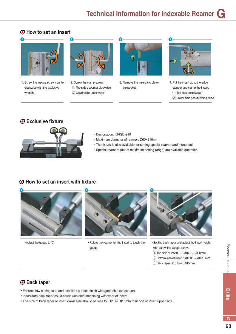
Drills
63
G
GR
eamer
Technical Information for Indexable Reamer
How to set an insert
Exclusive fixture
How to set an insert with fixture
Back taper
2. Screw the clamp screw.
Top side : counter clockwise
Lower side : clockwise
3. Remove the insert and clean
the pocket.
• Adjust the gauge to ‘0’. • Rotate the reamer for the insert to touch the
gauge.
1 2 3 4
1 2 3
• Designation: KIRSD-210
• Maximum diameter of reamer: Ø60×210mm
• The fixture is also available for setting special reamer and mono tool.
• Special reamers (out of maximum setting range) are available quotation.
• Ensures low cutting load and excellent surface finish with good chip evacuation.
• Inaccurate back taper could cause unstable machining with wear of insert.
• The size of back taper of insert down side should be less to 0.010~0.015mm than one of insert upper side.
4. Put the insert up to the edge
stopper and clamp the insert.
Top side : clockwise
Lower side : counterclockwise
1. Screw the wedge screw counter
clockwise with the exclusive
wrench.
• Set the back taper and adjust the insert height
with screw the wedge screw.
Top side of insert : +0.015 ~ +0.020mm
Bottom side of insert : +0.005 ~ +0.010mm
Back taper : 0.010 ~ 0.015mm
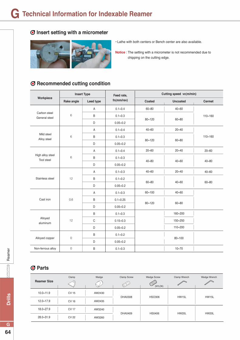
Dri
lls
64
G
GR
eam
er
Technical Information for Indexable Reamer
Insert setting with a micrometer
Recommended cutting condition
Parts
• Lathe with both centers or Bench center are also available.
Notice : The setting with a micrometer is not recommended due to
chipping on the cutting edge.
Carbon steel
General steel
Mild steel
Alloy steel
High alloy steel
Tool steel
Stainless steel
Cast iron
Alloyed
aluminum
Alloyed copper
Non-ferrous alloy
6
6
6
12
0.6
12
0
0
A
B
D
A
B
D
A
B
D
A
B
D
A
B
D
B
C
D
B
D
B
0.1~0.4
0.1~0.3
0.05~0.2
0.1~0.4
0.1~0.3
0.05~0.2
0.1~0.4
0.1~0.3
0.05~0.2
0.1~0.3
0.1~0.2
0.05~0.2
0.1~0.3
0.1~0.25
0.05~0.2
0.1~0.3
0.15~0.3
0.05~0.2
0.1~0.2
0.05~0.2
0.1~0.3
60~80
40~60
20~60
40~60
60~100
40~60
20~40
20~40 20~60
20~40 40~60
40~60
160~200
150~250
10~70
110~200
80~100
110~160
110~160
80~120 60~80
80~120 60~80
40~80 40~60 40~80
60~80 40~60 60~80
80~120 60~80
WorkpieceInsert Type
Rake angle Leed type Coated Uncoated Cermet
Feed rate,
fn(mm/rev)
Cutting speed vc(m/min)
DHA0308 HSO306 HW15L HW15L
DHA0409 HS0406 HW20L HW20L
CV 15
CV 16
CV 17
CV 22
AW2430
AW2435
AW3240
AW3260
10.0~11.9
12.0~17.9
18.0~27.9
28.0~31.9
Reamer SizeClamp Clamp Screw
(NYLOK)
Clamp WrenchWedge ScrewWedge Wedge Wrench
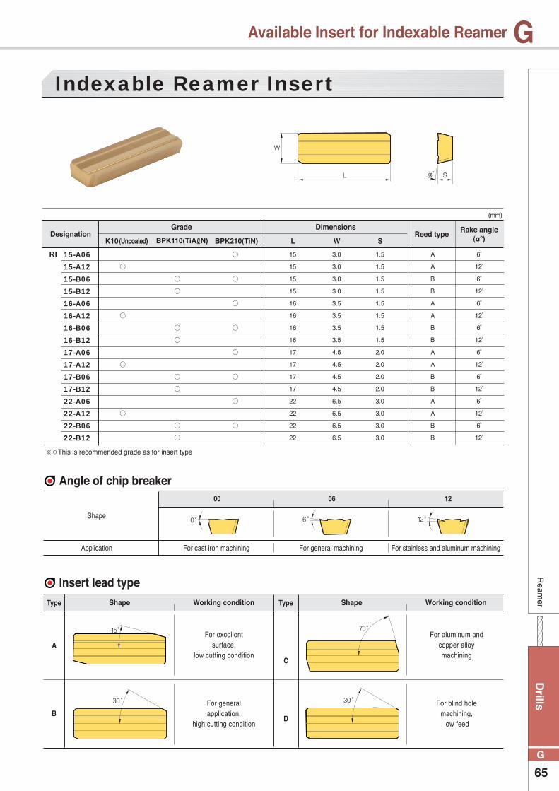
Drills
65
G
GR
eamer
Available Insert for Indexable Reamer
◯
◯
◯
◯
15
15
15
15
16
16
16
16
17
17
17
17
22
22
22
22
3.0
3.0
3.0
3.0
3.5
3.5
3.5
3.5
4.5
4.5
4.5
4.5
6.5
6.5
6.5
6.5
1.5
1.5
1.5
1.5
1.5
1.5
1.5
1.5
2.0
2.0
2.0
2.0
3.0
3.0
3.0
3.0
A
A
B
B
A
A
B
B
A
A
B
B
A
A
B
B
6˚
12˚
6˚
12˚
6˚
12˚
6˚
12˚
6˚
12˚
6˚
12˚
6˚
12˚
6˚
12˚
15-A06
15-A12
15-B06
15-B12
16-A06
16-A12
16-B06
16-B12
17-A06
17-A12
17-B06
17-B12
22-A06
22-A12
22-B06
22-B12
Indexable Reamer Insert
(mm)
DesignationK10(Uncoated)
◯
◯
◯
◯
◯
◯
◯
◯
BPK110(TiAℓN)
◯
◯
◯
◯
◯
◯
◯
◯
BPK210(TiN) L W S
DimensionsGradeReed type
Rake angle(α°)
RI
※○This is recommended grade as for insert type
Angle of chip breaker
Insert lead type
Type Type
Shape
Shape ShapeWorking condition Working condition
Application For cast iron machining
For excellent surface,
low cutting condition
For aluminum andcopper alloymachining
For generalapplication,
high cutting condition
For blind holemachining,
low feed
A
C
BD
For general machining For stainless and aluminum machining
00 06 12
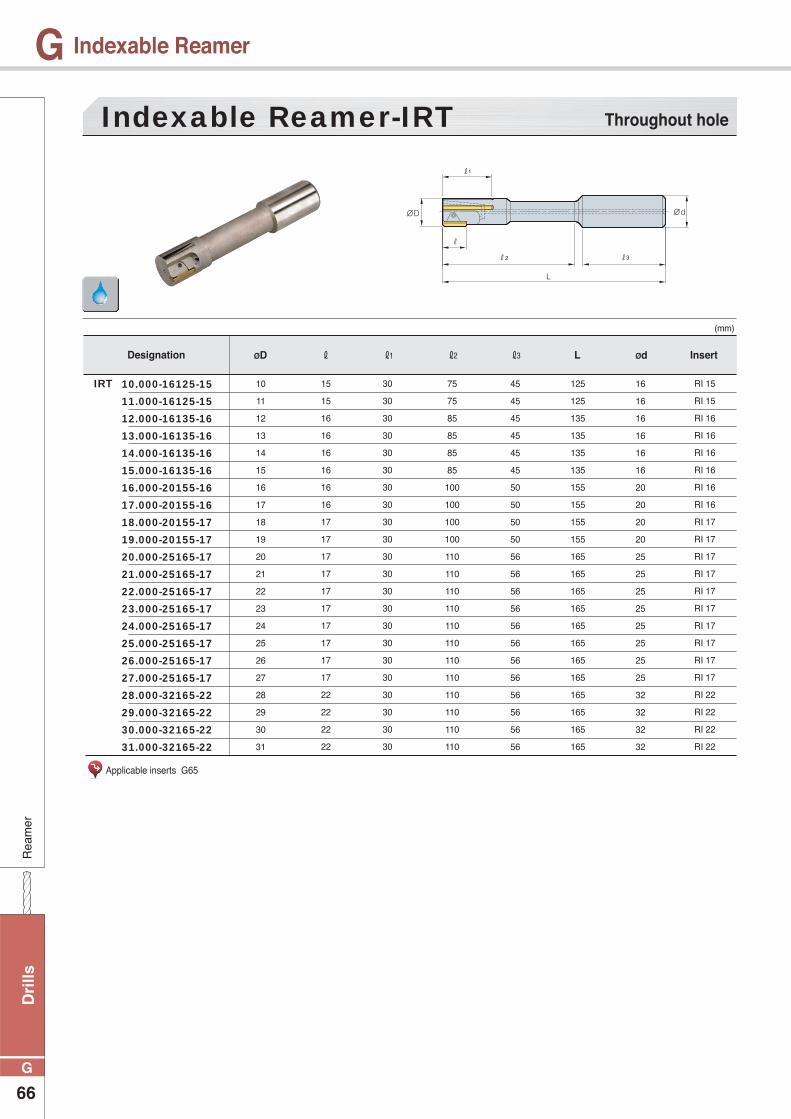
Dri
lls
66
G
GR
eam
er
Indexable Reamer
10
11
12
13
14
15
16
17
18
19
20
21
22
23
24
25
26
27
28
29
30
31
16
16
16
16
16
16
20
20
20
20
25
25
25
25
25
25
25
25
32
32
32
32
45
45
45
45
45
45
50
50
50
50
56
56
56
56
56
56
56
56
56
56
56
56
75
75
85
85
85
85
100
100
100
100
110
110
110
110
110
110
110
110
110
110
110
110
125
125
135
135
135
135
155
155
155
155
165
165
165
165
165
165
165
165
165
165
165
165
15
15
16
16
16
16
16
16
17
17
17
17
17
17
17
17
17
17
22
22
22
22
30
30
30
30
30
30
30
30
30
30
30
30
30
30
30
30
30
30
30
30
30
30
RI 15
RI 15
RI 16
RI 16
RI 16
RI 16
RI 16
RI 16
RI 17
RI 17
RI 17
RI 17
RI 17
RI 17
RI 17
RI 17
RI 17
RI 17
RI 22
RI 22
RI 22
RI 22
10.000-16125-15
11.000-16125-15
12.000-16135-16
13.000-16135-16
14.000-16135-16
15.000-16135-16
16.000-20155-16
17.000-20155-16
18.000-20155-17
19.000-20155-17
20.000-25165-17
21.000-25165-17
22.000-25165-17
23.000-25165-17
24.000-25165-17
25.000-25165-17
26.000-25165-17
27.000-25165-17
28.000-32165-22
29.000-32165-22
30.000-32165-22
31.000-32165-22
Indexable Reamer-IRT
(mm)
Designation ØD ØdLℓ3ℓ2ℓ1ℓ Insert
IRT
Throughout hole
Applicable inserts G65
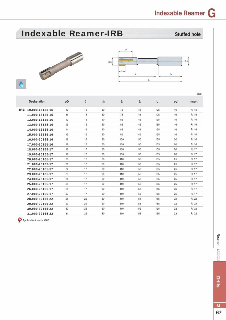
Drills
67
G
GR
eamer
Indexable Reamer
10
11
12
13
14
15
16
17
18
19
20
21
22
23
24
25
26
27
28
29
30
31
16
16
16
16
16
16
20
20
20
20
25
25
25
25
25
25
25
25
32
32
32
32
45
45
45
45
45
45
50
50
50
50
56
56
56
56
56
56
56
56
56
56
56
56
75
75
85
85
85
85
100
100
100
100
110
110
110
110
110
110
110
110
110
110
110
110
125
125
135
135
135
135
155
155
155
155
165
165
165
165
165
165
165
165
165
165
165
165
15
15
16
16
16
16
16
16
17
17
17
17
17
17
17
17
17
17
22
22
22
22
30
30
30
30
30
30
30
30
30
30
30
30
30
30
30
30
30
30
30
30
30
30
RI 15
RI 15
RI 16
RI 16
RI 16
RI 16
RI 16
RI 16
RI 17
RI 17
RI 17
RI 17
RI 17
RI 17
RI 17
RI 17
RI 17
RI 17
RI 22
RI 22
RI 22
RI 22
10.000-16125-15
11.000-16125-15
12.000-16135-16
13.000-16135-16
14.000-16135-16
15.000-16135-16
16.000-20155-16
17.000-20155-16
18.000-20155-17
19.000-20155-17
20.000-25165-17
21.000-25165-17
22.000-25165-17
23.000-25165-17
24.000-25165-17
25.000-25165-17
26.000-25165-17
27.000-25165-17
28.000-32165-22
29.000-32165-22
30.000-32165-22
31.000-32165-22
Indexable Reamer-IRB
(mm)
Designation ØD ØdLℓ3ℓ2ℓ1ℓ Insert
IRB
Stuffed hole
Applicable inserts G65
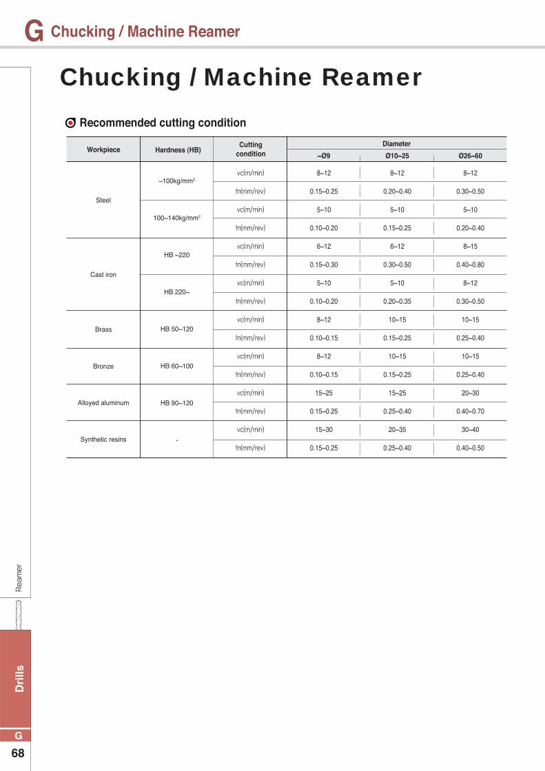
Dri
lls
68
G
GReamer
Chucking / Machine Reamer
Recommended cutting condition
Steel
~100kg/mm2
100~140kg/mm2
HB ~220
HB 220~
HB 50~120
HB 60~100
HB 90~120
-
Brass
Cast iron
Bronze
Alloyed aluminum
Synthetic resins
vc(m/min)
fn(mm/rev)
vc(m/min)
fn(mm/rev)
vc(m/min)
fn(mm/rev)
vc(m/min)
fn(mm/rev)
vc(m/min)
fn(mm/rev)
vc(m/min)
fn(mm/rev)
vc(m/min)
fn(mm/rev)
vc(m/min)
fn(mm/rev)
Workpiece Hardness (HB)DiameterCutting
condition
8~12
0.15~0.25
5~10
0.10~0.20
6~12
0.15~0.30
5~10
0.10~0.20
8~12
0.10~0.15
8~12
0.10~0.15
15~25
0.15~0.25
15~30
0.15~0.25
~Ø9
8~12
0.20~0.40
5~10
0.15~0.25
6~12
0.30~0.50
5~10
0.20~0.35
10~15
0.15~0.25
10~15
0.15~0.25
15~25
0.25~0.40
20~35
0.25~0.40
Ø10~25
8~12
0.30~0.50
5~10
0.20~0.40
8~15
0.40~0.80
8~12
0.30~0.50
10~15
0.25~0.40
10~15
0.25~0.40
20~30
0.40~0.70
30~40
0.40~0.50
Ø26~60
Chucking / Machine Reamer
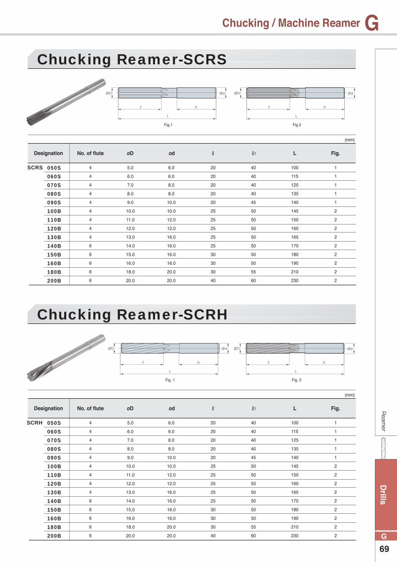
Drills
69
G
GReamer
Chucking / Machine Reamer
5.0
6.0
7.0
8.0
9.0
10.0
11.0
12.0
13.0
14.0
15.0
16.0
18.0
20.0
5.0
6.0
7.0
8.0
9.0
10.0
11.0
12.0
13.0
14.0
15.0
16.0
18.0
20.0
6.0
6.0
8.0
8.0
10.0
10.0
12.0
12.0
16.0
16.0
16.0
16.0
20.0
20.0
6.0
6.0
8.0
8.0
10.0
10.0
12.0
12.0
16.0
16.0
16.0
16.0
20.0
20.0
20
20
20
20
20
25
25
25
25
25
30
30
30
40
20
20
20
20
20
25
25
25
25
25
30
30
30
40
40
40
40
40
45
50
50
50
50
50
50
50
55
60
40
40
40
40
45
50
50
50
50
50
50
50
55
60
100
115
125
135
140
145
150
160
165
170
180
190
210
230
100
115
125
135
140
145
150
160
165
170
180
190
210
230
1
1
1
1
1
2
2
2
2
2
2
2
2
2
1
1
1
1
1
2
2
2
2
2
2
2
2
2
4
4
4
4
4
4
4
4
4
6
6
6
6
6
4
4
4
4
4
4
4
4
4
6
6
6
6
6
050S
060S
070S
080S
090S
100B
110B
120B
130B
140B
150B
160B
180B
200B
050S
060S
070S
080S
090S
100B
110B
120B
130B
140B
150B
160B
180B
200B
Chucking Reamer-SCRS
Chucking Reamer-SCRH
(mm)
(mm)
Designation
Designation
ØD
ØD
Ød
Ød
L
L
ℓ
ℓ
ℓ1
ℓ1
Fig.
Fig.
No. of flute
No. of flute
SCRS
SCRH
Fig.1
Fig. 1
Fig.2
Fig. 2
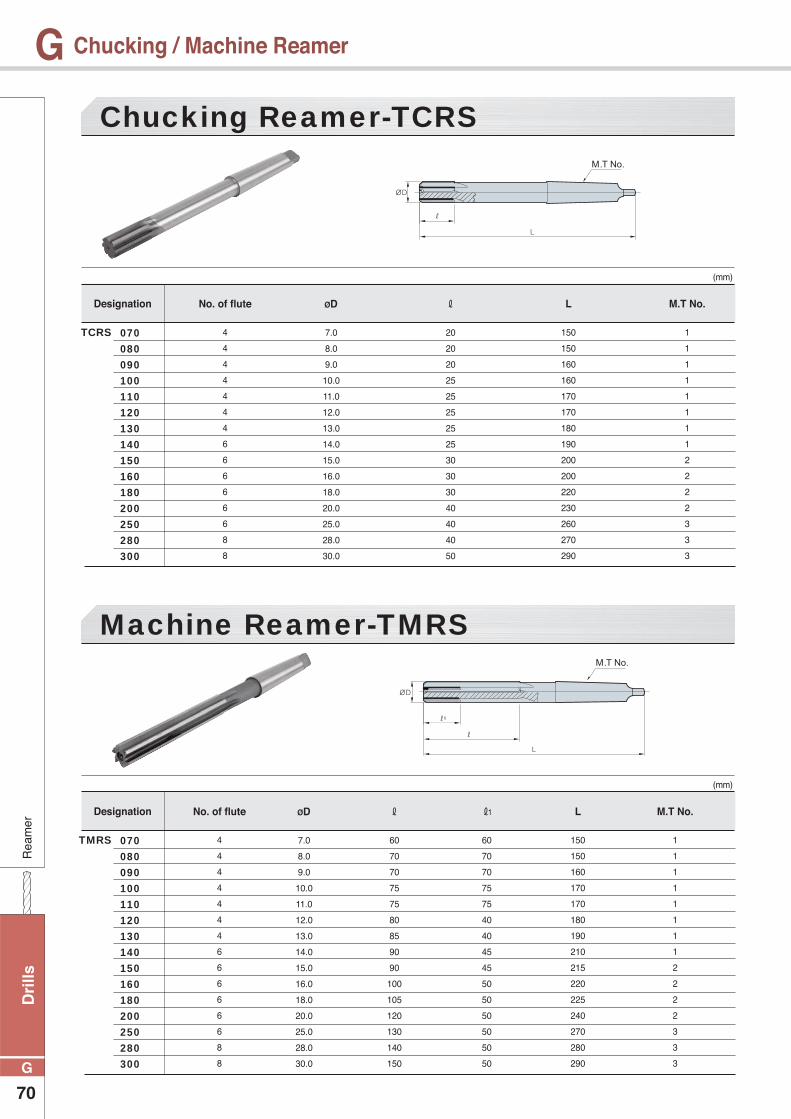
Dri
lls
70
G
GR
eam
er
Chucking / Machine Reamer
7.0
8.0
9.0
10.0
11.0
12.0
13.0
14.0
15.0
16.0
18.0
20.0
25.0
28.0
30.0
7.0
8.0
9.0
10.0
11.0
12.0
13.0
14.0
15.0
16.0
18.0
20.0
25.0
28.0
30.0
20
20
20
25
25
25
25
25
30
30
30
40
40
40
50
60
70
70
75
75
80
85
90
90
100
105
120
130
140
150
60
70
70
75
75
40
40
45
45
50
50
50
50
50
50
150
150
160
160
170
170
180
190
200
200
220
230
260
270
290
150
150
160
170
170
180
190
210
215
220
225
240
270
280
290
1
1
1
1
1
1
1
1
2
2
2
2
3
3
3
1
1
1
1
1
1
1
1
2
2
2
2
3
3
3
4
4
4
4
4
4
4
6
6
6
6
6
6
8
8
4
4
4
4
4
4
4
6
6
6
6
6
6
8
8
070
080
090
100
110
120
130
140
150
160
180
200
250
280
300
070
080
090
100
110
120
130
140
150
160
180
200
250
280
300
Chucking Reamer-TCRS
Machine Reamer-TMRS
(mm)
(mm)
Designation
Designation
ØD
ØD
L
L
M.T No.
M.T No.
ℓ
ℓ ℓ1
No. of flute
No. of flute
TCRS
TMRS

Drills
71
G
GR
eamer
PCD Reamer
30
40
40
40
40
40
50
50
50
50
60
60
5.0
6.0
7.0
8.0
9.0
10.0
12.0
14.0
15.0
16.0
18.0
20.0
2
2
2
2
2
2
2
2
2
4
4
4
65
75
75
75
85
85
95
95
100
100
110
110
6.0
6.0
8.0
8.0
10.0
10.0
12.0
16.0
16.0
16.0
20.0
20.0
2050
2060
2070
2080
2090
2100
2120
2140
2150
4160
4180
4200
PCD Reamer - PDR
(mm)
Designation ℓØDNo. of flute LØd
PDR
PCD Reamer
Type Tooth DiameterPCD Reamer 2 : 2flute 070 : Ø7.0
PDR 2 070
Code system
Recommended cutting conditionWorkpiece
50~250 0.05~0.20Aluminum alloy
vc(m/min) fn(mm/rev)
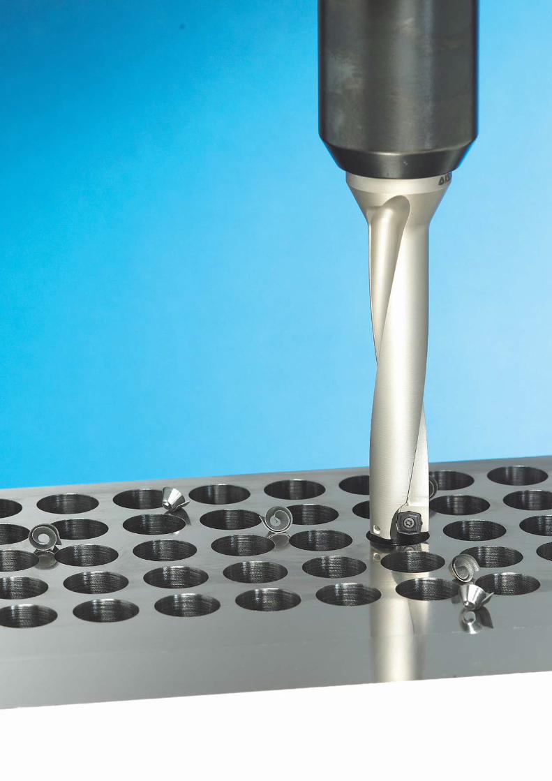
Dri
lls제목
72
G
상단제목G