Embed Size (px)
Citation preview

DI-1
DRIVER INFORMATION SYSTEM
K ELECTRICAL
CONTENTS
C
D
E
F
G
H
I
J
L
M
SECTION DIA
B
DI
Revision; 2004 April 2003 M45
DRIVER INFORMATION SYSTEM
PRECAUTIONS .......................................................... 4Precautions for Supplemental Restraint System (SRS) “AIR BAG” and “SEAT BELT PRE-TEN-SIONER” .................................................................. 4Wiring Diagrams and Trouble Diagnosis .................. 4
PREPARATION ........................................................... 5Commercial Service Tools ........................................ 5
COMBINATION METERS ........................................... 6System Description .................................................. 6
UNIFIED CONTROL METER ................................ 6HOW TO CHANGE THE DISPLAY FOR ODO/TRIP METER ........................................................ 6POWER SUPPLY AND GROUND CIRCUIT ........ 6WATER TEMPERATURE GAUGE ........................ 7TACHOMETER ..................................................... 7FUEL GAUGE ....................................................... 7SPEEDOMETER ................................................... 7
CAN Communication ................................................ 8SYSTEM DESCRIPTION ...................................... 8WITH ICC SYSTEM .............................................. 8WITHOUT ICC SYSTEM ...................................... 9
Component Parts and Harness Connector Location ... 10Combination Meter ..................................................11
CHECK .................................................................11Schematic .............................................................. 12Wiring Diagram — METER — ................................ 13Terminals and Reference Value for Combination Meter ...................................................................... 15Meter/Gauges Operation, Odo/Trip Meter, A/T Indi-cator and ICC System Display ............................... 15
SELF–DIAGNOSIS FUNCTION .......................... 15HOW TO ALTERNATE DIAGNOSIS MODE ....... 15
How to Proceed With Trouble Diagnosis ................ 16Diagnosis Flow ....................................................... 16Power Supply and Ground Circuit Inspection ........ 18Trouble Diagnosis Chart by Symptom .................... 19
DIAGNOSIS RESULTS ....................................... 19Inspection/Engine Speed Signal ............................ 19Inspection/Water Temperature Signal .................... 19Inspection/Vehicle Speed Signal ............................ 19
Inspection/Fuel Level Sensor Unit .......................... 20FUEL LEVEL SENSOR UNIT ............................. 20LOW-FUEL WARNING LAMP ............................. 20
Fuel Gauge Pointer Fluctuates·Indicator Wrong Value·or Varies ....................................................... 22Fuel Gauge Does Not Move to FULL Position ....... 22Fuel Gauge Does Not Work ................................... 23Low-Fuel Warning Lamp Illuminate or Not Illuminate
... 23Electrical Components Inspection .......................... 24
CHECK FUEL LEVEL SENSOR UNIT ................ 24Removal and Installation of Combination Meter ..... 24
REMOVAL ........................................................... 24INSTALLATION ................................................... 24
Disassembly and Assembly of Combination Meter ... 25COMPASS ................................................................. 26
System Description ................................................. 26DIRECTION DISPLAY ......................................... 26
Wiring Diagram – COMPAS – ................................ 28Removal and Installation of Compass .................... 29
WARNING LAMPS .................................................... 30System Description ................................................. 30
OUTLINE ............................................................. 30AIR BAG WARNING LAMP ................................. 30DOOR WARNING LAMP ..................................... 30LOW OIL PRESSURE WARNING LAMP ............ 30CHARGE WARNING LAMP ................................ 30LOW WASHER LEVEL WARNING LAMP .......... 30A/T CHECK WARNING LAMP ............................ 31LOW FUEL LEVEL WARNING LAMP ................. 31ABS WARNING LAMP ........................................ 31VDC OFF WARNING LAMP ................................ 31SLIP WARNING LAMP ........................................ 31SEAT BELT WARNING LAMP ............................. 31BRAKE WARNING LAMP ................................... 31MALFUNCTION INDICATOR LAMP ................... 32LOW TIRE PRESSURE WARNING LAMP ......... 32ASCD WARNING LAMP ..................................... 32ICC SYSTEM WARNING LAMP ......................... 32WARNING MESSAGE ON DISPLAY .................. 32

DI-2Revision; 2004 April 2003 M45
Schematic ............................................................... 33Wiring Diagram — WARN — .................................. 34Terminals and Reference Value for BCM ................ 42Work Flow ............................................................... 42Preliminary Inspection ............................................ 42CONSULT-II Function ............................................. 42
DIAGNOSTIC ITEMS DESCRIPTION ................. 42CONSULT-II BASIC OPERATION PROCEDURE
... 43DATA MONITOR .................................................. 44ACTIVE TEST ..................................................... 44
On Board Diagnosis ............................................... 44DIAGNOSIS ITEM ............................................... 44SWITCH MONITOR ............................................ 45
Trouble Diagnosis for Door Warning Lamp ............. 46Inspection/Combination Meter Circuit ..................... 46Inspection/Front Door Switch ................................. 46Inspection/Rear Door Switch .................................. 47Electrical Components Inspection .......................... 49
OIL PRESSURE SWITCH ................................... 49A/T INDICATOR ........................................................ 50
Wiring Diagram — AT/IND — ................................. 50A/T Indicator Does Not Illuminate ........................... 51
WARNING CHIME ..................................................... 52System Description ................................................. 52
FUNCTION .......................................................... 52IGNITION KEY WARNING CHIME ...................... 52LIGHT WARNING CHIME ................................... 52SEAT BELT WARNING CHIME ........................... 53
Component Parts and Harness Connector Location ... 53Major Component Parts and Function .................... 53Schematic ............................................................... 54Wiring Diagram — CHIME — ................................. 55Terminals and Reference Value Chart for BCM ...... 59Work Flow ............................................................... 59Preliminary Inspection ............................................ 60
INSPECTION FOR POWER SUPPLY AND GROUND CIRCUIT ............................................. 60
CONSULT-II Function ............................................. 61DIAGNOSTIC ITEMS DESCRIPTION ................. 61CONSULT-II BASIC OPERATION PROCEDURE
... 61DATA MONITOR .................................................. 62ACTIVE TEST ..................................................... 63
On Board Diagnosis ............................................... 63DIAGNOSIS ITEM ............................................... 63SWITCH MONITOR ............................................ 63
Symptom Chart ....................................................... 64Warning Chime Circuit Inspection .......................... 65Front Door Switch (Driver side) Inspection ............. 66Key Switch Insert Signal Inspection ....................... 67Lighting Switch Input Signal Inspection .................. 68Seat Belt Buckle Switch Inspection ........................ 70Removal and Installation of Warning Chime ........... 71
REMOVAL ........................................................... 71INSTALLATION .................................................... 71
VEHICLE INFORMATION AND INTEGRATED SWITCH SYSTEM /WITH NAVIGATION SYSTEM ... 72
System Description ................................................. 72
INTEGRATED SWITCH SYSTEM .......................72PRECAUTION OF LCD MONITOR .....................72POWER SUPPLY AND GROUND .......................72AV COMMUNICATION LINE ...............................72VEHICLE INFORMATION SYSTEM ....................73SETTING OF VEHICLE STATUS ........................75WARNING INDICATIONS ....................................78
Precautions for AV and NAVI Control Unit Replace-ment ........................................................................80Component Parts and Harness Connector Location ...80Schematic ...............................................................81Wring Diagram — INF/D — ....................................82Terminals and Reference Value for AV and NAVI Control Unit .............................................................87Terminals and Reference Value for Display ............87Terminals and Reference Value for Multifunction Switch .....................................................................89On Board Self-Diagnosis Function ..........................89
DESCRIPTION ....................................................89DIAGNOSIS ITEM ...............................................90
Self-Diagnosis Mode ...............................................90Confirmation/Adjustment Mode ...............................90CONSULT-ll Function ..............................................90Multifunction Switch Self-Diagnosis Function .........90
STARTING THE SELF-DIAGNOSIS MODE ........90EXITING THE SELF-DIAGNOSIS MODE ...........91DIAGNOSIS FUNCTION .....................................91
Power Supply and Ground Circuit Check for AV and NAVI Control Unit ....................................................91Power Supply and Ground Circuit Inspection for Dis-play .........................................................................92Power Supply and Ground Circuit Inspection for Multifunction Switch ................................................93No Fuel Information Is Displayed/No Warning Mes-sage Is Displayed ....................................................93Vehicle Condition Setting Is Not Possible. ..............94Multifunction Switch Does Not Operate ..................95Multifunction Switch Indicator Does Not illuminate ...96Removal and Installation of Display ........................96
REMOVAL ............................................................96INSTALLATION ....................................................96
Disassembly and Assembly for Multifunction Switch ...97
Removal and Installation of AV and NAVI Control Unit ..........................................................................98
REMOVAL ............................................................98INSTALLATION ....................................................98
VEHICLE INFORMATION AND INTEGRATED SWITCH SYSTEM /WITHOUT NAVIGATION SYS-TEM ...........................................................................99
System Description .................................................99INTEGRATED SWITCH SYSTEM .......................99PRECAUTION OF LCD MONITOR .....................99POWER SUPPLY AND GROUND .......................99AV COMMUNICATION LINE ...............................99VEHICLE INFORMATION SYSTEM ..................100SETTING OF VEHICLE STATUS ......................102WARNING INDICATIONS ..................................105
Precautions for AV Control Unit Replacement ......107

DI-3
C
D
E
F
G
H
I
J
L
M
A
B
DI
Revision; 2004 April 2003 M45
Component Parts and Harness Connector Location . 107Schematic ............................................................ 108Wiring Diagram — INF/D — ................................. 109Schematic .............................................................114Wiring Diagram — COMM — ................................115Terminals and Reference Value for AV Control Unit ..119Terminals and Reference Value for Display ......... 122Terminals and Reference Value for Multifunction Switch ................................................................... 125On Board Self-Diagnosis Function (without CON-SULT-II) ................................................................ 126
DESCRIPTION .................................................. 126DIAGNOSIS ITEM ............................................. 126
Self-Diagnosis Mode ............................................ 127OPERATION PROCEDURE ............................. 127SELF-DIAGNOSIS RESULT ............................. 129
Confirmation/Adjustment Mode ............................ 131OPERATION PROCEDURE ............................. 131DISPLAY DIAGNOSIS ...................................... 132VEHICLE SIGNALS .......................................... 133AUTO CLIMATE CONTROL ............................. 133
CONSULT-II Function .......................................... 134CONSULT-II BASIC OPERATION PROCEDURE
. 134SELF-DIAG RESULTS ...................................... 135DATA MONITOR ............................................... 135VERSION .......................................................... 136
Multifunction Switch Self-Diagnosis Function ...... 136STARTING THE SELF-DIAGNOSIS MODE ..... 136EXITING THE SELF-DIAGNOSIS MODE ......... 136DIAGNOSIS FUNCTION ................................... 136
Power Supply and Ground Circuit Inspection for AV Control Unit .......................................................... 137Power Supply and Ground Circuit Inspection for Dis-play ....................................................................... 138Inspection of Multifunction Switch for Power Supply and Ground Circuit ............................................... 139Vehicle Speed Signal Inspection .......................... 140Illumination Control Signal Inspection .................. 141Ignition Signal Inspection ..................................... 141RGB Screen is not Shown ................................... 142Color of RGB Image is not Proper ....................... 143RGB Screen Is Rolling ......................................... 145No A/C Display is Shown ..................................... 146A/C Operation Is Not Possible ............................. 147No Fuel Information Is Displayed/No Warning Mes-sage Is Displayed ................................................. 148
Vehicle Condition Setting Is Not Possible ............. 149Multifunction Switch Does Not Operate ................ 150Multifunction Switch Indicator Does Not illuminate . 150Removal and Installation of Display ..................... 151
REMOVAL ......................................................... 151INSTALLATION ................................................. 151
Disassembly and Assembly of Multifunction Switch . 152Removal and Installation of AV Control Unit ......... 153
REMOVAL ......................................................... 153INSTALLATION ................................................. 153
CLOCK .................................................................... 154Wiring Diagram — CLOCK — .............................. 154Removal and Installation ...................................... 155
REMOVAL ......................................................... 155INSTALLATION ................................................. 155
VOICE ACTIVATED CONTROL SYSTEM .............. 156System Description ............................................... 156
OUTLINE ........................................................... 156VOICE ACTIVATED CONTROL FUNCTION .... 156AV COMMUNICATION LINE ............................. 157
Schematic ............................................................. 158Wiring Diagram — VOICE — ............................... 159Terminals and Reference Values for Voice Activated Control Module ..................................................... 164Component Parts and Harness Connector Location . 165Trouble Diagnoses ............................................... 166
THIS CONDITION IS NOT MALFUNCTION ..... 166Self-Diagnosis Function ........................................ 166
DESCRIPTION .................................................. 166DIAGNOSIS ITEM ............................................. 166
Self-Diagnosis Mode ............................................ 166OPERATION PROCEDURE .............................. 166
Confirmation/Adjustment Mode ............................ 167OPERATION PROCEDURE .............................. 167
Power Supply and Ground Circuit Inspection ....... 168Voice Command Not Identified (With Voice Acti-vated Control System in Operation) ..................... 169No Guide Sound or Beeps .................................... 170Voice Activated Control System Not Starting PTT Switch Pushed ON ............................................... 171Audio Not Muted with PTT Switch Pushed ON .... 173Audio Mute Not Released ..................................... 174Removal and Installation for Voice Activated Control Module .................................................................. 175
REMOVAL ......................................................... 175INSTALLATION ................................................. 175

DI-4
PRECAUTIONS
Revision; 2004 April 2003 M45
PRECAUTIONS PFP:00011
Precautions for Supplemental Restraint System (SRS) “AIR BAG” and “SEAT BELT PRE-TENSIONER” AKS004Z4
The Supplemental Restraint System such as “AIR BAG” and “SEAT BELT PRE-TENSIONER”, used alongwith a front seat belt, helps to reduce the risk or severity of injury to the driver and front passenger for certaintypes of collision. This system includes seat belt switch inputs and dual stage front air bag modules. The SRSsystem uses the seat belt switches to determine the front air bag deployment, and may only deploy one frontair bag, depending on the severity of a collision and whether the front occupants are belted or unbelted.Information necessary to service the system safely is included in the SRS and SB section of this Service Man-ual.WARNING: To avoid rendering the SRS inoperative, which could increase the risk of personal injury or death
in the event of a collision which would result in air bag inflation, all maintenance must be per-formed by an authorized NISSAN/INFINITI dealer.
Improper maintenance, including incorrect removal and installation of the SRS, can lead to per-sonal injury caused by unintentional activation of the system. For removal of Spiral Cable and AirBag Module, see the SRS section.
Do not use electrical test equipment on any circuit related to the SRS unless instructed to in thisService Manual. SRS wiring harnesses can be identified by yellow and/or orange harnesses orharness connectors.
Wiring Diagrams and Trouble Diagnosis AKS004Z5
When you read wiring diagrams, refer to the following: Refer to GI-14, "How to Read Wiring Diagrams" in GI section Refer to PG-2, "POWER SUPPLY ROUTING" for power distribution circuit in PG sectionWhen you perform trouble diagnosis, refer to the following: Refer to GI-10, "HOW TO FOLLOW TEST GROUPS IN TROUBLE DIAGNOSES" in GI section Refer to GI-26, "How to Perform Efficient Diagnosis for an Electrical Incident" in GI section

PREPARATION
DI-5
C
D
E
F
G
H
I
J
L
M
A
B
DI
Revision; 2004 April 2003 M45
PREPARATION PFP:00002
Commercial Service Tools AKS003VD
Tool name Description
Power tool
Loosening bolts and nuts
PBIC0191E

DI-6
COMBINATION METERS
Revision; 2004 April 2003 M45
COMBINATION METERS PFP:24814
System Description AKS002HM
UNIFIED CONTROL METER Speedometer, odo/trip meter, tachometer, fuel gauge and water temperature gauge are controlled totally
by control unit built in combination meter. Digital meter is adopted for odo/trip meter.*
*The record of the odo meter is kept even if the battery cable is disconnected. The record of the trip meteris erased when the battery cable is disconnected.
Odo/trip meter, A/T indicator and ICC system display segments can be checked in self-diagnosis mode. Meter/gauge can be checked in self-diagnosis mode.
HOW TO CHANGE THE DISPLAY FOR ODO/TRIP METER The CAN communication signals (vehicle speed signal) from VDC/TCS/ABS control unit, and the memory
signals from the meter memory circuit are processed by the combination meter, and the mileage is dis-played.
Operating the odo/trip meter switch allows switching the mode in the following order.
The odometer/trip display switching and trip display resetting can be identified by the time from pressingthe odometer/trip switch to releasing it.
When resetting with trip A displayed, only trip A display is reset (same as trip B).
POWER SUPPLY AND GROUND CIRCUITPower is supplied at all times through 10A fuse [No. 6, located in the fuse block (J/B) NO. 1] to combination meter terminal 39.With the ignition switch in the ON or START position, power is supplied through 10A fuse [No. 9, located in the fuse block (J/B) NO. 1] to combination meter terminals 40 and 42.With the ignition switch in the ACC or ON position, power is supplied through 10A fuse [No. 21, located in the fuse block (J/B) NO. 1] to combination meter terminal 28.Ground is supplied to combination meter terminals 20 and 33 through body grounds M24 and M114.
SEL175W

COMBINATION METERS
DI-7
C
D
E
F
G
H
I
J
L
M
A
B
DI
Revision; 2004 April 2003 M45
WATER TEMPERATURE GAUGEThe water temperature gauge indicates the engine coolant temperature.ECM provides an engine coolant temperature signal to combination meter for water temperature gauge withCAN communication line.
TACHOMETERThe tachometer indicates engine speed in revolution per minutes (rpm).ECM provides a engine speed signal to combination meter for tachometer with CAN communication line.
FUEL GAUGEThe fuel gauge indicates the approximate fuel level in the fuel tank.The fuel gauge is regulated by a variable resister signal supplied to combination meter terminal 30 for the fuel level sensor from terminal 5 of the fuel level sensor unit through terminal 6 of the fuel level sensor unit and through combination meter terminal 31.
SPEEDOMETERVDC/TCS/ABS control unit provides a vehicle speed signal to the combination meter for the speedometer withCAN communication line.

DI-8
COMBINATION METERS
Revision; 2004 April 2003 M45
CAN Communication AKS002HN
SYSTEM DESCRIPTIONCAN (Controller Area Network) is a serial communication line for real time application. It is an on-vehicle mul-tiplex communication line with high data communication speed and excellent error detection ability. Many elec-tronic control units are equipped onto a vehicle, and each control unit shares information and links with othercontrol units during operation (not independent). In CAN communication, control units are connected with 2communication lines (CAN H line, CAN L line) allowing a high rate of information transmission with less wiring.Each control unit transmits/receives data but selectively reads required data only.
WITH ICC SYSTEMSystem diagram
Input/output signal chartT: Transmit R: Receive
SKIA3838E
Signals ECM
VDC/TCS/ABS
control unit
ICC sen-sor
ICC unit TCMSteering
angle sensor
Combina-tion meter
ICC system display signal T R
ICC sensor signal T R
ICC operation signal T R
Engine speed signal T R R R R
Engine coolant temperature signal T R R
Accelerator pedal position signal T R R R
Engine torque signal T R R
Battery voltage signal T R
Closed throttle position signal T R R
Wide open throttle position signal T R
Engine and A/T integrated control signalT R
R T
Fuel consumption monitor signal T R
A/T CHECK indicator signal T R
A/T position indicator signal T R
Current gear position signal R R R T R
Next gear position signal R R R T
Shift change signal R R T
Shift pattern signal R R T
VDC operation signal R T R
Stop lamp switch signal R T
Steering angle sensor signal R T
Air conditioner switch signal R T

COMBINATION METERS
DI-9
C
D
E
F
G
H
I
J
L
M
A
B
DI
Revision; 2004 April 2003 M45
WITHOUT ICC SYSTEMSystem diagram
Input/output signal chartT: Transmit R: Receive
Headlamp switch signal R T
Rear window defogger switch signal R T
OD cancel switch signal R T
Vehicle speed signalT R R
R R T
Output shaft revolution signal R R T
ABS operation signal R T R R
TCS operation signal R T R
A/T shift schedule change demand signal T R
Manual mode signal R R T
Not manual mode signal R T
Manual mode shift up signal R T
Manual mode shift down signal R T
Manual mode indicator signal T R
Signals ECM
VDC/TCS/ABS
control unit
ICC sen-sor
ICC unit TCMSteering
angle sensor
Combina-tion meter
SKIA3837E
Signals ECMVDC/TCS/ABS
control unitTCM
Steering angle sensor
Combination meter
Engine speed signal T R R R
Engine coolant temperature signal T R
Accelerator pedal position signal T R R
Engine torque signal T R R
Battery voltage signal T R
Closed throttle position signal T R
Wide open throttle position signal T R
Engine and A/T integrated control signalT R
R T
Fuel consumption monitor signal T R
A/T CHECK indicator signal T R
A/T position indicator signal T R
Current gear position signal R R T R
Next gear position signal R R T

DI-10
COMBINATION METERS
Revision; 2004 April 2003 M45
Component Parts and Harness Connector Location AKS002HO
Shift change signal R R T
Shift pattern signal R T
VDC operation signal R T
Stop lamp switch signal R T
Steering angle sensor signal R T
Air conditioner switch signal R T
Headlamp switch signal R T
Rear window defogger switch signal R T
OD cancel switch signal R T
Vehicle speed signalT R
R R T
Output shaft revolution signal R T
ABS operation signal R T R
TCS operation signal R T
A/T shift schedule change demand signal T R
ASCD operation signal R R T
Overdrive cancel signal R R T
Manual mode signal R T
Not manual mode signal R T
Manual mode shift up signal R T
Manual mode shift down signal R T
Manual mode indicator signal T R
Signals ECMVDC/TCS/ABS
control unitTCM
Steering angle sensor
Combination meter
SKIA9268E

COMBINATION METERS
DI-11
C
D
E
F
G
H
I
J
L
M
A
B
DI
Revision; 2004 April 2003 M45
Combination Meter AKS002HP
CHECK
SKIA3836E

DI-12
COMBINATION METERS
Revision; 2004 April 2003 M45
Schematic AKS002HR
TKWA0578E

COMBINATION METERS
DI-13
C
D
E
F
G
H
I
J
L
M
A
B
DI
Revision; 2004 April 2003 M45
Wiring Diagram — METER — AKS002HS
TKWA0579E

DI-14
COMBINATION METERS
Revision; 2004 April 2003 M45
TKWA0580E

COMBINATION METERS
DI-15
C
D
E
F
G
H
I
J
L
M
A
B
DI
Revision; 2004 April 2003 M45
Terminals and Reference Value for Combination Meter AKS002HU
Meter/Gauges Operation, Odo/Trip Meter, A/T Indicator and ICC System DisplayAKS002HV
SELF–DIAGNOSIS FUNCTION Odo/trip meter segment, A/T indicator segment and ICC system display can be checked in self-diagnosis
mode. Meters/gauges can be checked in self-diagnoses mode.
HOW TO ALTERNATE DIAGNOSIS MODE1. Turn ignition switch ON, and switch the odo/ trip meter to “trip A” or “trip B”.
NOTE:If the diagnosis function is activated with the trip meter A displayed, the mileage on the trip meter A isreset to 0.0km (same as the trip meter B display).
2. Turn ignition switch OFF.3. While pushing the odo/trip meter switch, turn ignition switch ON again.4. Check that the trip meter displays “0000.0”.5. Push the odo/trip meter switch at least 3 times. (Within 7 seconds after the ignition switch is turned ON.)
Terminal No.
Wire color
Item
Condition
Reference valueIgnition switch
Operation
20 B Ground ON — Approx. 0V
28 L/OR Ignition switch (ACC) ACC — Battery voltage
30 R/Y Fuel level senor signal ON —Refer to DI-24, "Electrical Compo-nents Inspection" .
31 B/Y Fuel level sensor ground ON — —
33 B Ground ON — Approx. 0V
34 L CAN H — — —
35 R CAN L — — —
37 OR/L Vehicle speed signal (8-pulse) ONSpeedometer operated[When vehicle speed is approx. 40km/h (25MPH)]
38 PU/W Vehicle speed signal (2-pulse) ONSpeedometer operated[When vehicle speed is approx. 40km/h (25MPH)]
39 Y/G Battery source (BAT) OFF — Battery voltage
40G Ignition switch (ON) ON — Battery voltage
42
ELF1084D
ELF1080D

DI-16
COMBINATION METERS
Revision; 2004 April 2003 M45
6. All the segments on the odo/trip meter, A/T indicator and ICC system display illuminate, and simulta-neously the low-fuel warning lamp indicator illuminate. At this time, the unified control meter is turned todiagnosis mode.
NOTE:If any of the segments is not displayed, replace the odo/trip meter and A/T indicator with the speedometerassembly.
7. Push the odo/trip meter switch. Indication of each meter/gaugeshould be as shown in the right during pushing odo/trip meterswitch if there is no malfunctioning. (at this time, the low-fuelwarning lamp goes off).
How to Proceed With Trouble Diagnosis AKS002VG
1. Confirm the trouble symptom or customer complaint.2. Perform diagnosis according to diagnosis flow. Refer to DI-16, "Diagnosis Flow" .3. According to the trouble diagnosis chart, repair or replace the cause of the trouble symptom. Refer to DI-
19, "Trouble Diagnosis Chart by Symptom" .4. Does the meter operate normally? Yes: Go to 5. No: Go to 2.5. Inspection end.
Diagnosis Flow AKS002VH
1. CHECK WARNING LAMP ILLUMINATION
1. Turn ignition switch ON.2. Make sure that warning lamps (such as MIL and oil pressure warning lamp) illuminate.Do warning lamps illuminate?YES >> O TO 2.NO >> Check ignition power supply system of combination meter. Refer to DI-18, "Power Supply and
Ground Circuit Inspection" .
2. CHECK SELF-DIAGNOSIS OPERATION
Perform combination meter self-diagnosis. Refer to DI-15, "SELF–DIAGNOSIS FUNCTION" .Does self-diagnosis function operate?YES >> GO TO 3.NO >> Check battery power supply of combination meter and ground system. Refer to DI-18, "Power
Supply and Ground Circuit Inspection" .
MKIB0204E
SKIA2097E

COMBINATION METERS
DI-17
C
D
E
F
G
H
I
J
L
M
A
B
DI
Revision; 2004 April 2003 M45
3. CHECK ODO/TRIP METER OPERATION
Check segment display status of odo/trip meter. Refer to DI-15,"SELF–DIAGNOSIS FUNCTION" .Is the display normal?YES >> GO TO 4.NO >> Replace combination meter.
4. CHECK FUEL WARNING LAMP ILLUMINATION
During fuel warning lamp check, confirm illumination of fuel warning lamp.
OK or NGOK >> GO TO 5.NG >> Replace combination meter.
5. CHECK METER CIRCUIT
Check indication of each meter/gauge in self-diagnosis mode. Referto DI-15, "SELF–DIAGNOSIS FUNCTION" .OK or NGOK >> Go to diagnosis results. Refer to DI-19, "DIAGNOSIS
RESULTS" .NG >> Replace combination meter.
SEL176W
Condition of odo/trip meter switch Fuel warning lamp
Pushed Does not illuminate.
Released Illuminates.
SKIA2097E
DI-18
COMBINATION METERS
Revision; 2004 April 2003 M45
Power Supply and Ground Circuit Inspection AKS002HY
1. CHECK FUSES
Check that any of the fuses in combination meter is blown.
OK or NGOK >> GO TO 2.NG >> If fuse is blown, be sure to eliminate cause of problem before installing new fuse. Refer to PG-2,
"POWER SUPPLY ROUTING" .
2. CHECK POWER SUPPLY CIRCUIT
1. Disconnect the combination meter connector.2. Check voltage between combination meter and ground.
OK or NGOK >> GO TO 3.NG >> Check harness for open or short between combination meter and fuse.
3. CHECK GROUND CIRCUIT
1. Turn ignition switch OFF.2. Check continuity between combination meter harness connector
M41 terminals 20 (B), 33 (B) and ground.
OK or NGOK >> Inspection end.NG >> Check ground harness.
Unit Power source Fuse No.
Combination meter
Battery 6
Ignition switch ON or START 9
Ignition switch ACC or ON 21
Terminals Ignition switch position
(+)
(–) OFF ACC ONConnector
Terminal(Wire color)
M41
28 (L/OR)
Ground
0VBattery voltage
Battery voltage
39 (Y/G)Battery voltage
Battery voltage
Battery voltage
40 (G)0V 0V
Battery voltageM42 42 (G)
SKIA3422E
Continuity should exist.
SKIA3423E

COMBINATION METERS
DI-19
C
D
E
F
G
H
I
J
L
M
A
B
DI
Revision; 2004 April 2003 M45
Trouble Diagnosis Chart by Symptom AKS002VL
DIAGNOSIS RESULTS
Inspection/Engine Speed Signal AKS002VI
1. CHECK ECM SELF-DIAGNOSIS
Perform ECM self-diagnosis. Refer to EC-52, "Emission-related Diagnostic Information" .OK or NGOK >> Replace combination meter.NG >> Perform “Diagnostic procedure” displayed DTC.
Inspection/Water Temperature Signal AKS002VJ
1. CHECK ECM SELF-DIAGNOSIS
Preform the ECM self-diagnosis. Refer to EC-52, "Emission-related Diagnostic Information" . OK or NGOK >> Replace combination meter.NG >> Perform “Diagnostic procedure” displayed DTC.
Inspection/Vehicle Speed Signal AKS002VK
1. CHECK VDC/TCS/ABS CONTROL UNIT SELF-DIAGNOSIS
Perform VDC/TCS/ABS control unit self-diagnosis. Refer to BRC-13, "TROUBLE DIAGNOSIS" .OK or NGOK >> Replace combination meter.NG >> Perform “Diagnostic procedure” displayed self-diagnosis results.
Trouble phenomenon Possible cause
Fuel warning lamp indication is irregular. Replace combination meter.
Indication is malfunction for one of the following: tachometer, fuel gauge, or water temperature gauge
Refer to DI-20, "Inspection/Fuel Level Sensor Unit" .
Refer to DI-19, "Inspection/Engine Speed Signal" .
Refer to DI-19, "Inspection/Water Temperature Signal" .
Indication is irregular for the speedometer and odo/trip meter. Refer to DI-19, "Inspection/Vehicle Speed Signal" .
Indications are irregular for more than one gauge. Replace combination meter.
A/T position indicator is malfunction. Refer to DI-51, "A/T Indicator Does Not Illuminate" .
ICC system display does not illuminate.Refer to ACS-58, "TROUBLE DIAGNOSIS — GENERAL DESCRIPTION" .

DI-20
COMBINATION METERS
Revision; 2004 April 2003 M45
Inspection/Fuel Level Sensor Unit AKS002I3
FUEL LEVEL SENSOR UNITThe following symptoms do not indicate a malfunction. Depending on vehicle posture or driving circumstance, the fuel level in the tank various, and the pointer
may fluctuate. If the vehicle is fueled with the ignition switch ON, the pointer will move slowly. If vehicle is tilted when the ignition switch is turned ON, fuel in the tank may flow to one direction resulting
in a change in the reading.
LOW-FUEL WARNING LAMPDepending on vehicle posture or driving circumstance, the fuel level in the tank varies, and the warning lampON timing may be changed.
1. CHECK SELF-DIAGNOSIS
Preform the combination meter self–diagnosis mode. Refer to DI-15, "Meter/Gauges Operation, Odo/TripMeter, A/T Indicator and ICC System Display" .OK or NGOK >> GO TO 2.NG >> Replace combination meter.
2. CHECK HARNESS CONNECTOR
1. Turn ignition switch OFF.2. Check combination meter, fuel level sensor unit and terminals (meter-side, module-side, lead-side, and
harness-side) for poor connection and bend.OK or NGOK >> GO TO 3.NG >> Repair terminal or connector.
3. CHECK HARNESS CONNECTOR OUTPUT SIGNAL
1. Disconnect fuel level sensor connector.2. Turn ignition switch ON.3. Check voltage between combination meter harness connector
M41 terminal 30 (R/Y) and ground.
OK or NGOK >> GO TO 4.NG >> Replace combination meter.
Approx. 5V
SKIA3424E

COMBINATION METERS
DI-21
C
D
E
F
G
H
I
J
L
M
A
B
DI
Revision; 2004 April 2003 M45
4. CHECK HARNESS FOR OPEN OR SHORT CIRCUIT
1. Turn ignition switch OFF.2. Disconnect combination meter connector.3. Check the following.– Continuity between combination meter harness connector M41
terminal 30 (R/Y) and fuel level sensor unit harness connectorB51 terminal 5 (R/Y)
– Continuity between combination meter harness connector M41terminal 30 (R/Y) and ground
4.
OK or NGOK >> GO TO 5.NG >> Repair harness or connector.
5. CHECK FUEL LEVEL SENSOR GROUND CIRCUIT
Check the following. Continuity between combination meter harness connector M41
terminal 31 (B/Y) and fuel level sensor unit harness connectorB51 terminal 6 (B)
Continuity between combination meter harness connector M41terminal 31 (B/Y) and ground
OK or NGOK >> GO TO 6.NG >> Repair harness or connector.
6. CHECK FUEL LEVEL SENSOR UNIT
Check the components. Refer to DI-24, "CHECK FUEL LEVEL SENSOR UNIT" .OK or NGOK >> GO TO 7.NG >> Replace fuel level sensor unit.
7. CHECK INSTALLATION CONDITION
Check fuel level sensor unit installation, and check whether the float arm interferes or binds with any compo-nents inside the arm.OK or NGOK >> Replace combination meter.NG >> Install fuel level sensor unit properly.
Continuity should exist.
Continuity should not exist. SKIA3425E
Continuity should exist.
Continuity should not exist.SKIA3427E

DI-22
COMBINATION METERS
Revision; 2004 April 2003 M45
Fuel Gauge Pointer Fluctuates·Indicator Wrong Value·or Varies AKS002I4
1. CHECK FUEL GAUGE POINTER FOR FLUCTUATION
Does the indication value fluctuate during driving or before/after stop?Does the indication value vary?YES >> The pointer fluctuation may be caused by fuel level change in the fuel tank.NO >> Ask the customer about the situation when the symptom occurs in detail, and Preform the trouble
diagnosis.
Fuel Gauge Does Not Move to FULL Position AKS002I5
1. QUESTION 1
Does it take a long time for the pointer to move to FULL position?YES or NOYES >> GO TO 2.NO >> GO TO 3.
2. QUESTION 2
Was the vehicle fueled with the ignition switch ON?YES or NOYES >> Be sure to fuel the vehicle with the ignition switch OFF. Otherwise it will take a long time to move
to FULL position because of the characteristic of the fuel gauge.NO >> GO TO 3.
3. QUESTION 3
Is the floor or the vehicle inclined?YES or NOYES >> It may not be filled fully.NO >> GO TO 4.
4. QUESTION 4
During driving, does the fuel gauge pointer move gradually toward EMPTY position?YES or NOYES >> Check the components. Refer to DI-20, "FUEL LEVEL SENSOR UNIT" .NO >> The float arm may interfere or bind with any of the components in the fuel tank.
COMBINATION METERS
DI-23
C
D
E
F
G
H
I
J
L
M
A
B
DI
Revision; 2004 April 2003 M45
Fuel Gauge Does Not Work AKS002I6
1. CHECK HARNESS CONNECTOR
Check combination meter, fuel level sensor unit, and terminals (meter-side, unit-side and harness-side) forpoor connection and bend.OK or NGOK >> GO TO 2.NG >> Repair terminals or connector.
2. CHECK INSTALLATION CONDITION
Check fuel level sensor unit installation (refer to FL-3, "FUEL LEVEL SENSOR UNIT, FUEL FILTER ANDFUEL PUMP ASSEMBLY" , and check whether the float arm interferes or binds with any components insidethe arm.OK or NGOK >> Check fuel level sensor unit. Refer to DI-20, "Inspection/Fuel Level Sensor Unit" .NG >> Install fuel level sensor unit properly.
Low-Fuel Warning Lamp Illuminate or Not Illuminate AKS002I7
1. CHECK SELF-DIAGNOSIS
Preform combination meter self-diagnosis mode. Refer to DI-15, "Meter/Gauges Operation, Odo/Trip Meter, A/T Indicator and ICC System Display" .OK or NGOK >> Check fuel level sensor unit. Refer to DI-20, "FUEL LEVEL SENSOR UNIT" .NG >> Replace combination meter.
DI-24
COMBINATION METERS
Revision; 2004 April 2003 M45
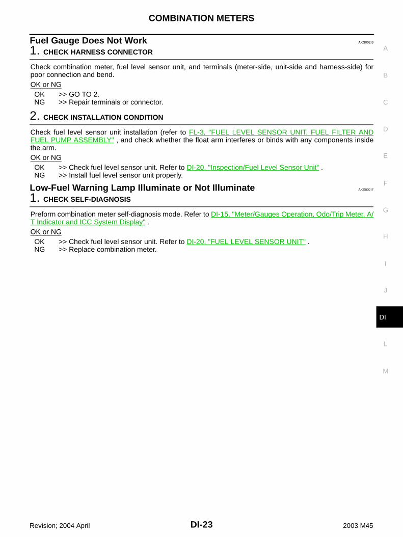
Electrical Components Inspection AKS002I9
CHECK FUEL LEVEL SENSOR UNIT For removal, refer to FL-3, "FUEL LEVEL SENSOR UNIT, FUEL FILTER AND FUEL PUMP ASSEMBLY"
. Check the resistance between terminals 5 and 6.
Removal and Installation of Combination Meter AKS002IA
REMOVAL1. Remove cluster lid A. Refer to IP-10, "INSTRUMENT PANEL ASSEMBLY" .2. Remove screws (3) with power tool, and disconnect connectors.
3. While pulling combination meter upper-side forward, pull it out.CAUTION:To prevent it from being damaged by interference with themeter bracket, protect the meter with cloth.
INSTALLATIONInstall in the reverse order of removal.
Terminal Float position mm (in) Resistance value Ω
5 6
Full (3) Approx. 82.7 (3.3) Approx. 4.5 - 5.5
1/2 (2) Approx. 200.3 (7.9) Approx. 31.5 - 35.5
Empty (1) Approx. 325.0 (12.8) Approx. 80.0 - 83.0
SKIA3428E
PKIA1666E
PKIA1667E

COMBINATION METERS
DI-25
C
D
E
F
G
H
I
J
L
M
A
B
DI
Revision; 2004 April 2003 M45
Disassembly and Assembly of Combination Meter AKS002IB
1. Disengage tabs (8) to separate meter cover.2. Disengage tabs (8) to separate upper housing.3. Disengage tabs (8) to separate front cover.
1. Front cover 2. Upper housing 3. Unified meter control unit assembly
4. Meter cover
PKIA1668E

DI-26
COMPASS
Revision; 2004 April 2003 M45
COMPASS PFP:24835
System Description AKS003ZP
This unit displays earth magnetism and heading direction of vehicle.
DIRECTION DISPLAYPush the switch when the ignition key is in the “ON” or “START” position. The direction will be displayed.Pushing the “COMP” switch a second time will turn off the display.1. If the display reads “C” calibrate the compass by driving the vehicle in 3 complete circles at less than 8km/
h (5MPH).2. To adjust for Compass Variance:a. Press the “COMP” switch for more than 3 seconds. The current zone number will appear in the display.b. Find your current location and variance zone number on the zone map.c. Press the “COMP” switch until the new zone number appears in the display. After you stop pressing the
button in, the display will show a compass direction within a few seconds.NOTE:1. Do not install the ski rack, antenna, etc. which are attached to the vehicle by means of a magnet. They
affect the operation of the compass.2. If the compass deviates from the correct indication soon after repeated adjustment, have the compass
checked at an authorized dealer.3. The compass may not indicate the correct compass point in tunnels or while driving up or down a steep
hill. (The compass returns to the correct compass point when the vehicle moves to an area where thegeomagnetism is stabilized.)
3. Cleaning the MirrorWhen cleaning the mirror, use a paper towel or similar mate-rial dampened with glass cleaner. Do notspray glass cleaner directly on the mirror as that may cause the liquid cleaner to enter the mirror housing.
SKIA4100E

COMPASS
DI-27
C
D
E
F
G
H
I
J
L
M
A
B
DI
Revision; 2004 April 2003 M45
“C” is displayed in the compass window.The compass needs to be calibrated. Drive the vehicle in 3 circles at8km/h (5MPH) or less until the display reads a direction. You canalso calibrate the compass by driving your vehicle on your everydayroutine. The compass will be calibrated once it has tracked 3 com-plete circles.
Inaccurate compass direction1. With the display turned on, push the “COMP” switch for 3 seconds, until the Zone selection comes up (a
number will be displayed in the mirror compass window).2. Toggle until correct zone is found and release switch.3. The display will show all segments, and return to the normal compass mode within 10 seconds of no
switch activity.4. If the vehicle changes zone, repeat steps 1 through 3. See map.
SEL168Y

DI-28
COMPASS
Revision; 2004 April 2003 M45
Wiring Diagram – COMPAS – AKS003LW
TKWA0619E

COMPASS
DI-29
C
D
E
F
G
H
I
J
L
M
A
B
DI
Revision; 2004 April 2003 M45
Removal and Installation of Compass AKS0040J
Refer to GW-59, "Removal and Installation" .

DI-30
WARNING LAMPS
Revision; 2004 April 2003 M45
WARNING LAMPS PFP:24814
System Description AKS002IC
OUTLINEPower is supplied at all times through 10A fuse [No. 6, located in the fuse block (J/B) NO.1] to combination meter terminal 39.With ignition switch in the ON or START position, power is supplied through 10A fuse [No. 9, located in the fuse block (J/B) NO.1] to combination meter terminals 40 and 42.Ground is supplied to combination meter terminals 20 and 33 through body grounds M24 and M114, and to seat belt buckle switch terminal 15A (with automatic drive positioner) or 14 (without automatic drive
positioner) through body grounds B17 and B57, and to brake fluid level switch terminal 2 and to washer level switch terminal 2 through body grounds E42 and E62.
AIR BAG WARNING LAMPDuring probe out or when an air bag malfunction occurs, the ground path is interrupted from the air bag diagnosis sensor unit terminal 15 to combination meter terminal 5.Ground is supplied to combination meter terminal 45 through body grounds M24 and M114.When power and ground are supplied, the air bag warning lamp (LEDs) illuminates.For further information, refer to SRS-8, "TROUBLE DIAGNOSIS" .
DOOR WARNING LAMPDoor waning lamp is controlled by BCM.When one of the doors is opened, ground is supplied to the BCM terminals 33, 37, 142 and 143.And then ground is supplied to combination meter terminal 3 from BCM terminal 111.When power and ground are supplied, the door warning lamp illuminates.
LOW OIL PRESSURE WARNING LAMPLow oil pressure causes oil pressure switch terminal 1 to provide ground to combination meter terminal 63.When power and ground are supplied, the low oil pressure warning lamp illuminates.
CHARGE WARNING LAMPDuring prove out or when a alternator malfunction occurs, ground is supplied to combination meter terminal 64 from alternator terminal 3.When power and ground are supplied, the charge warning lamp and brake lamp illuminate.
LOW WASHER LEVEL WARNING LAMPWhen the washer fluid level is low, ground is supplied to combination meter terminal 16 from washer level switch terminal 1.When power and ground are supplied, the signal is sent from combination meter terminals 56 and 57

WARNING LAMPS
DI-31
C
D
E
F
G
H
I
J
L
M
A
B
DI
Revision; 2004 April 2003 M45
through AV and NAVI control unit terminals 32 and 33 or AV control unit terminals 34 and 35 to display.Then warning lamp message appears display.
A/T CHECK WARNING LAMPWhen an A/T system malfunction occurs, signal sent to combination meter terminals 34 and 35 from TCM (transmission control module) with CAN communication line.When signal is received, the AT oil temp warning lamp blinks or illuminates.For further information, refer to AT-242, "A/T CHECK Indicator Lamp does not come on" .
LOW FUEL LEVEL WARNING LAMPThe amount of fuel in the fuel tank is determined by the fuel level sensor in the fuel tank. Fuel level signal issent from fuel level sensor unit terminal 5 to combination meter terminal 30 through fuel level sensor unit terminal 6 to combination meter terminal 31.The fuel level sensor will illuminate the low fuel level warning lamp when the fuel level is low.When power and ground are supplied, the low fuel level warning lamp illuminates.
ABS WARNING LAMPWhen an ABS malfunction occurs, ground is supplied to combination meter terminal 6 from VDC/TCS/ABS control unit terminal 30.When power and ground is supplied, the ABS warning lamp illuminates.For further information, refer to BRC-40, "BASIC INSPECTION 3 ABS WARNING LAMP, VDC OFF LAMP,SLIP LAMP INSPECTION" .
VDC OFF WARNING LAMPWhen VDC off switch is in OFF position, or an VDC/TCS/ABS malfunction occurs, ground is supplied to combination meter terminal 51 from VDC/TCS/ABS control unit terminal 31.When power and ground are supplied, the VDC off warning lamp illuminates.For further information, refer to BRC-40, "BASIC INSPECTION 3 ABS WARNING LAMP, VDC OFF LAMP,SLIP LAMP INSPECTION" .
SLIP WARNING LAMPWhen VDC is in operation, or a VDC malfunction occurs, ground is supplied to combination meter terminal 11 from VDC/TCS/ABS control unit terminal 83.When power and ground are supplied, the slip warning lamp illuminates.For further information, refer to BRC-40, "BASIC INSPECTION 3 ABS WARNING LAMP, VDC OFF LAMP,SLIP LAMP INSPECTION" .
SEAT BELT WARNING LAMPWhen the driver's seat belt is unfastened, ground is supplied to combination meter terminal 8 from seat belt buckle switch terminal 41.When power and ground are supplied, the seat belt warning lamp illuminates.
BRAKE WARNING LAMPWhen the parking brake is applied, or the brake fluid level is low, ground is supplied to combination meter terminal 22 from parking brake switch terminal 1, or to combination meter terminal 21

DI-32
WARNING LAMPS
Revision; 2004 April 2003 M45
brake fluid level switch terminal 1.When power and ground are supplied, the brake warning lamp illuminates.
MALFUNCTION INDICATOR LAMPDuring prove out or when an engine control malfunction occurs, ground is supplied to combination meter terminal 52 from ECM terminal 35.When power and ground are supplied, the malfunction indicator lamp illuminates.For further information, refer to EC-410, "DTC P0650 MIL" .
LOW TIRE PRESSURE WARNING LAMPWhen a low tire pressure warning control malfunction occurs, ground is supplied to combination meter terminal 7 from low tire pressure warning control unit terminal 3.When power and ground are supplied, the tire pressure warning lamp illuminates.For further information, refer to WT-23, "TROUBLE DIAGNOSIS FOR SYMPTOMS" .
ASCD WARNING LAMPWhen an ASCD malfunction occurs, ground is supplied to combination meter terminal 61 from ASCD control unit terminal 18.When power and ground are supplied, the ASCD warning lamp illuminates.
ICC SYSTEM WARNING LAMPWhen an ICC system malfunction occurs, ground is supplied to combination meter terminal 53 from ICC unit terminal 25.When power and ground are supplied, the ICC system warning lamp illuminates.
WARNING MESSAGE ON DISPLAYWhen a warning lamp illuminates or flushes, signal is sent from combination meter terminals 56 and 57 through AV and NAVI control unit terminals 32 and 33 or AV control unit terminals 34 and 35 to display.Then warning message appears on display.

WARNING LAMPS
DI-33
C
D
E
F
G
H
I
J
L
M
A
B
DI
Revision; 2004 April 2003 M45
Schematic AKS002ID
TKWA0583E

DI-34
WARNING LAMPS
Revision; 2004 April 2003 M45
Wiring Diagram — WARN — AKS002IE
TKWA0584E

WARNING LAMPS
DI-35
C
D
E
F
G
H
I
J
L
M
A
B
DI
Revision; 2004 April 2003 M45
TKWA0585E

DI-36
WARNING LAMPS
Revision; 2004 April 2003 M45
TKWA0586E

WARNING LAMPS
DI-37
C
D
E
F
G
H
I
J
L
M
A
B
DI
Revision; 2004 April 2003 M45
TKWA0587E

DI-38
WARNING LAMPS
Revision; 2004 April 2003 M45
TKWA0588E
WARNING LAMPS
DI-39
C
D
E
F
G
H
I
J
L
M
A
B
DI
Revision; 2004 April 2003 M45
TKWA0589E

DI-40
WARNING LAMPS
Revision; 2004 April 2003 M45
TKWA0590E
WARNING LAMPS
DI-41
C
D
E
F
G
H
I
J
L
M
A
B
DI
Revision; 2004 April 2003 M45
TKWA0591E

DI-42
WARNING LAMPS
Revision; 2004 April 2003 M45
Terminals and Reference Value for BCM AKS002IF
Work Flow AKS002IG
1. Check the symptom and customer's requests.2. Understand the outline of system. Refer to DI-30, "System Description" .3. Perform the preliminary inspection. Refer to DI-60, "Preliminary Inspection" .4. Referring to Trouble diagnosis chart, repair or replace the cause of the incident. Refer to DI-46, "Trouble
Diagnosis for Door Warning Lamp" .5. Does warning chime system operate normally? If it operates normally, go to step 6. If not, go to step 4.6. Inspection end.
Preliminary Inspection AKS002IH
Perform preliminary check, refer to DI-60, "Preliminary Inspection" .
CONSULT-II Function AKS002II
CONSULT-II executes the following functions by combining data reception and command transmission via thecommunication line from BCM. IVMS communication inspection, work support (only function setting of seatsand steering wheel), self-diagnosis, data monitor, and active test display.
DIAGNOSTIC ITEMS DESCRIPTION
Terminal No.
Wire color
Item
Condition
Reference valueIgnition switch
Operation or condition
33 WDoor lock assembly rear LH (door switch)
OFFON (open) Approx. 0
OFF (closed) Approx. 12
37 LGFront door switch (passenger side)
OFFON (open) Approx. 0
OFF (closed) Approx. 12
111 P/B Door warning lamp OFF Door switchON (open) Approx. 0
OFF (closed) Approx. 12
142 R/Y Front door switch (driver side) OFFON (open) Approx. 0
OFF (closed) Approx. 12
143 W/LDoor lock assembly rear RH (door switch)
OFFON (open) Approx. 0
OFF (closed) Approx. 12
IVMS diagnosis position Diagnosis mode Description
DOOR OPEN WARNINGData monitor The input data to the BCM control unit is displayed in real time.
Active test Operation of electrical loads can be checked by sending driving signal to them.
BCM PART NUMBER Displays BCM part No.

WARNING LAMPS
DI-43
C
D
E
F
G
H
I
J
L
M
A
B
DI
Revision; 2004 April 2003 M45
CONSULT-II BASIC OPERATION PROCEDURE1. With the ignition switch OFF, connect “CONSULT-II” and “CON-
SULT-ll CONVERTER” to the data link connector, and turn theignition switch ON.
2. Touch “START (NISSAN BASED VHCL)”.
3. Touch “IVMS” on “SELECT SYSTEM” screen.If “IVMS” is not indicated, go to GI-38, "CONSULT-II Data LinkConnector (DLC) Circuit" .
4. Check the model specification, touch either “WITH SUNROOF”or “WITHOUT SUNROOF”.
5. Touch “OK”. If the selection is wrong, touch “CANCEL”.
6. Select the desired part to be diagnosed on the “SELECT TEST ITEM” screen.
SHIA0179E
SKIA3098E
PIIA0183E
PIIA0184E

DI-44
WARNING LAMPS
Revision; 2004 April 2003 M45
DATA MONITOROperation Procedure1. Touch “DOOR OPEN WARNING” on “SELECT TEST ITEM” screen.2. Touch “DATA MONITOR” on “SELECT DIAG MODE” screen.3. Touch “MAIN SIGNALS” or “SELECTION FROM MENU” on “DATA MONITOR” screen.
4. Touch “START”.5. If “SELECTION FROM MENU” is selected, touch the desired monitor item. If “MAIN SIGNALS” is
selected, the main item required to control is monitored.6. During monitoring, touching “COPY” can start recording the monitor item status.
Data Monitor Item
ACTIVE TESTOperation Procedure1. Touch “DOOR OPEN WARNING” on “SELECT TEST ITEM” screen.2. Touch “ACTIVE TEST” on “SELECT DIAG MODE” screen.3. Touch the item to be tested, and check the operation.4. During the operation check, touching “OFF” deactivates the operation.
Active Test Item
On Board Diagnosis AKS002IJ
ON BOARD DIAGNOSTIC RESULTS INDICATOR LAMP Map lamps and step lamps (all seats) act an the indicators for the on board diagnosis.
DIAGNOSIS ITEM
MAIN SIGNALS Monitors the main items.
SELECTION FROM MENU Selects and monitors the items.
Monitored item Description
IGN ON SW Indicates [ON/OFF] condition of ignition switch.
DOOR SW-DR Indicates [ON/OFF] condition of front door switch (driver side).
DOOR SW-AS Indicates [ON/OFF] condition of front door switch (passenger side).
DOOR SW-RL Indicates [ON/OFF] condition of door lock assembly rear LH (door switch).
DOOR SW-RR Indicates [ON/OFF] condition of door lock assembly rear RH (door switch).
Test item. Malfunction detecting condition
DR OPN WARN LAMPThis test is able to check door warning lamp operation. Door warning lamp indicate when touch “ON” on CONSULT-ll screen.
Diagnosis item Description
Switch monitor Monitoring conditions of switches connected to BCM.

WARNING LAMPS
DI-45
C
D
E
F
G
H
I
J
L
M
A
B
DI
Revision; 2004 April 2003 M45
SWITCH MONITORPerform the diagnosis on the switch system to each control unit.
How to Perform Switch Monitor
DescriptionIn this mode, when BCM detects the input signal from a switch in IVMS as shown below, the detection is indi-cated by the map lamp and front step lamps with buzzer.
Switch Monitor ItemThe status of the switch (except the ignition switch, interior lamp switch, and map lamp switch) as input toeach control unit can be monitored.
Cancel of Switch Monitor Turn ignition switch OFF. Drive the vehicle at more than 7km/h (4MPH).
SIIA0411E
SEL960V
BCM
Front door switch (driver side)
Front door switch (passenger side)
Door lock assembly rear LH (door switch)
Door lock assembly rear RH (door switch)

DI-46
WARNING LAMPS
Revision; 2004 April 2003 M45
Trouble Diagnosis for Door Warning Lamp AKS002IK
Inspection/Combination Meter Circuit AKS002IL
1. CHECK DOOR WARNING LAMP INPUT SIGNAL
1. Disconnect BCM connector and combination meter connector.2. Check the following.– Continuity between BCM harness connector M4 terminal 111 (P/
B) and combination meter harness connector M41 terminal 3 (P/B)
– Continuity between BCM harness connector M4 terminal 111 (P/B) and ground
OK or NGOK >> GO TO 2.NG >> Repair harness or connector.
2. CHECK DOOR WARNING LAMP
1. Connect combination meter connector.2. Turn ignition switch ON.3. Check voltage between BCM harness connector M4 terminal
111 (P/B) and ground.
OK or NGOK >> Combination meter is OK.NG >> Replace combination meter.
Inspection/Front Door Switch AKS002IM
1. CHECK FRONT DOOR SWITCH OPERATION
With CONSULT-IISee “DOOR SW” on DATA MONITOR in DATA MONITOR mode.
Without CONSULT-IICheck front door switches in Switch monitor mode. Refer to DI-44,"On Board Diagnosis" .OK or NGOK >> Front door switch is OK.NG >> GO TO 2.
Symptom Diagnostic procedure and repair order
Door warning lamp does not illuminate with any of doors are open.
Check combination meter circuit. Refer to DI-46, "Inspection/Combination Meter Circuit" .
Check front door switch. Refer to DI-46, "Inspection/Front Door Switch" .
Check door lock assembly rear (door switch). Refer to DI-47, "Inspection/Rear Door Switch" .
If the above systems work properly, replace the BCM.
Door warning lamp illuminates constantly.
Continuity should exist
Continuity should not exist
SKIA3726E
Battery voltage should exist.
SKIA4129E
SEL498W

WARNING LAMPS
DI-47
C
D
E
F
G
H
I
J
L
M
A
B
DI
Revision; 2004 April 2003 M45
2. CHECK FRONT DOOR SWITCH OPEN OR SHORT CIRCUIT
1. Turn ignition switch OFF.2. Disconnect BCM connector and front door switches connector.3. Check the following.– Continuity between BCM harness connector B4 terminal 142 (R/
Y) and front door switch (driver side) harness connector B20 ter-minal 1 (R/Y)
– Continuity between BCM harness connector M4 terminals 37(LG) and front door switch (passenger side) harness connectorB220 terminal 1 (LG)
– Continuity between BCM harness connector M4, B4 terminals37 (LG), 142 (R/Y) and ground
OK or NGOK >> GO TO 3.NG >> Repair harness or connector.
3. CHECK FRONT DOOR SWITCH (DRIVER SIDE OR PASSENGER SIDE)
Check continuity between front door switch and ground.
OK or NGOK >> Front door switch is OK.NG >> Replace front door switch.
Inspection/Rear Door Switch AKS002IN
1. CHECK REAR DOOR SWITCH OPERATION
With CONSULT-IISee “DOOR SW” in DATA MONITOR mode.
Without CONSULT-IICheck rear doors switches in Switch monitor mode. Refer to DI-44,"On Board Diagnosis" .OK or NGOK >> Door lock assembly rear (door switch) is OK.NG >> GO TO 2.
Continuity should exist.
Continuity should exist.
Continuity should not exist.
SKIA3727E
Terminal Condition Continuity
1 GroundPressed No
Released Yes
SKIA4131E
SEL498W

DI-48
WARNING LAMPS
Revision; 2004 April 2003 M45
2. CHECK REAR DOOR SWITCH INPUT SIGNAL
1. Turn ignition switch OFF.2. Disconnect BCM connector and door lock assembly rear (door switch) connector.3. Check the following.– Continuity between BCM harness connector B4, M4 terminals
143 (W/L), 33 (W) and Door lock assembly rear RH (doorswitch) harness connector D82 terminal 1 (W) or Door lockassembly rear LH (door switch) harness connector D62 terminal1 (W)
– Continuity between BCM harness connector M4, B4 terminal 33(W), 143 (W/L) and ground
OK or NGOK >> GO TO 3.NG >> Repair harness or connector.
3. CHECK REAR DOOR SWITCH
Check continuity between door lock assembly rear (door switch) LHor RH harness connector D62 (LH), D82 (RH) terminal 2 and 1.
OK or NGOK >> GO TO 4.NG >> Replace door lock assembly rear (door switch).
4. CHECK REAR DOOR SWITCH GROUND CIRCUIT
Check continuity between door lock assembly rear (door switch) har-ness connector D62 or D82 terminal 2 (B) and ground.
OK or NGOK >> Door lock assembly rear (door switch) is OK.NG >> Repair harness or connector.
Continuity should exist.
Continuity should not exist.SKIA4132E
Terminal Condition Continuity
1 2Pressed No
Released Yes
SKIA4133E
Continuity should exist.
SKIA4105E

WARNING LAMPS
DI-49
C
D
E
F
G
H
I
J
L
M
A
B
DI
Revision; 2004 April 2003 M45
Electrical Components Inspection AKS002IO
OIL PRESSURE SWITCHCheck continuity between the oil pressure switch and ground.
Condition Oil pressure kPa (kg/cm2 , psi) Continuity
Engine stopped Less than 29 (0.3, 4) Yes
Engine running More than 29 (0.3, 4) No
ELF0044D

DI-50
A/T INDICATOR
Revision; 2004 April 2003 M45
A/T INDICATOR PFP:24814
Wiring Diagram — AT/IND — AKS002IP
TKWA0592E

A/T INDICATOR
DI-51
C
D
E
F
G
H
I
J
L
M
A
B
DI
Revision; 2004 April 2003 M45
A/T Indicator Does Not Illuminate AKS002IR
1. CHECK COMBINATION METER SELF-DIAGNOSIS
Perform combination meter self-diagnosis mode. Refer to DI-15, "Meter/Gauges Operation, Odo/Trip Meter, A/T Indicator and ICC System Display" .If it check from combination meter trouble diagnosis, go to next step.OK or NGOK >> A/T indicator is OKNG >> Replace combination meter.
2. CHECK TCM CONTROL UNIT SYSTEM
Perform TCM self-diagnosis. Refer to AT-87, "CONSULT-II" in AT section.OK or NGOK >> Replace combination meter.NG >> Perform “Diagnosis Procedure” displayed self-diagnosis results.

DI-52
WARNING CHIME
Revision; 2004 April 2003 M45
WARNING CHIME PFP:24814
System Description AKS002IS
FUNCTION
Power is supplied at all times through 10A fuse [No. 3, located in the fuse block (J/B) NO. 1] to BCM terminal 105, through 10A fuse [No. 32, located in the fuse block (J/B) NO. 2] to key switch and key lock solenoid (key switch) terminal 3, through 10A fuse [No. 6, located in the fuse block (J/B) NO. 1] to headlamp battery saver control unit terminal 7 and to warning chime terminal 1, and through 15A fuse [No. 54, located in the fuse, fusible link and relay block (J/B)] to tail lamp relay terminals 2 and 6 [located in fuse, fusible link and relay block (J/B)].With ignition switch in ON or START position, power is supplied through 10A fuse [No. 1, located in the fuse block (J/B) NO. 1] to BCM terminal 68.Ground is supplied to BCM terminals 56 and 113 through body grounds M24 and M114.When a signal, or combination of signals, is received by the BCM, the warning chime will sound.
IGNITION KEY WARNING CHIMEWith the key in the ignition key cylinder, power is supplied through key switch and key lock solenoid (key switch) terminal 4 to BCM terminal 69,When front door switch (driver side) is open, ground is supplied to BCM terminal 142 through front door (driver side) switch terminal 1. Front door switch (driver side) is case ground.With ignition switch in OFF or ACC position, and the driver's door open, ground is supplied to warning chime terminal 3 from BCM terminal 12.The warning chime will sound.
LIGHT WARNING CHIMEWhen lighting switch is in the 1st or 2nd position, ground is supplied to tail lamp relay terminal 1 through battery saver control unit terminals 6 and 14, to battery saver control unit terminals 5 and 13 through combination switch terminal 11 and to combination switch terminal 5 through body grounds M25 and M115.then tail lamp relay is energied, power is supplied
Item Description
Ignition key warning chimeSounds warning chime when driver’s door is opened with key in ignition key cylinder and ignition switch “OFF” or “ACC” position.
Light warning chimeSounds warning chime when driver’s door is opened with lighting switch in the 1st or 2nd position and ignition switch “OFF” or “ACC” position.
Seat belt warning chimeSounds warning chime for about 6 seconds if ignition switch is turned “ON” when driver’s seat belt is unfastened

WARNING CHIME
DI-53
C
D
E
F
G
H
I
J
L
M
A
B
DI
Revision; 2004 April 2003 M45
through tail lamp relay terminal 7 [located in fuse, fusible link and relay block (J/B)] to BCM terminal 3,When front door switch (driver side) is open, ground is supplied to BCM terminal 142. through front door switch (driver side) terminal 1.Front door switch (driver side) is case ground.With ignition switch OFF or ACC position, driver's door open, and lighting switch in 1ST or 2ND position,ground is supplied to warning chime terminal 3 from BCM terminal 12.The warning chime will sound. [Except when head lamp battery saver control operates (for 45 seconds afterignition switch is turned to OFF or ACC position) and head-lamps do not illuminate.]
SEAT BELT WARNING CHIMEWhen seat belt buckle switch is unfastened, ground is supplied to BCM terminal 147 through front power seat (seat belt buckle switch) terminals 15A (with automatic drive position) and 41or through front power seat (seat belt buckle switch) terminals 14 (without automatic drive positioner) and
41, and through body grounds B17 and B57.With ignition switch turned ON and seat belt unfastened (seat belt switch ON), ground is supplied to warning chime terminal 3 from BCM terminal 12.warning chime will sound for approximately 6 seconds.
Component Parts and Harness Connector Location AKS002IT
Major Component Parts and Function AKS002IU
SKIA9289E
Components Functions
BCMIt operates the warning chime intermittently by signals from the ignition switch, key detection switch, lighting switch, or front door switch (driver side) or seat belt buckle switch (driver side).
Warning chime It generates intermittent sounds by signals from the BCM.

DI-54
WARNING CHIME
Revision; 2004 April 2003 M45
Schematic AKS002IV
TKWA0593E

WARNING CHIME
DI-55
C
D
E
F
G
H
I
J
L
M
A
B
DI
Revision; 2004 April 2003 M45
Wiring Diagram — CHIME — AKS002IW
TKWA0594E

DI-56
WARNING CHIME
Revision; 2004 April 2003 M45
TKWA0595E
WARNING CHIME
DI-57
C
D
E
F
G
H
I
J
L
M
A
B
DI
Revision; 2004 April 2003 M45
TKWA0596E

DI-58
WARNING CHIME
Revision; 2004 April 2003 M45
TKWA0597E
WARNING CHIME
DI-59
C
D
E
F
G
H
I
J
L
M
A
B
DI
Revision; 2004 April 2003 M45
Terminals and Reference Value Chart for BCM AKS002IX
Work Flow AKS002IY
1. Check the trouble symptom and customer's requests.2. Understand the outline of system. Refer to DI-52, "System Description" .3. Perform the preliminary check. Refer to DI-60, "Preliminary Inspection" .4. Referring to Trouble diagnosis chart, repair or replace the cause of the incident. Refer to DI-64, "Symptom
Chart"5. Does warning chime system operate normally? If it operates normally, Go to step 6. If not, Go to step 4.6. Inspection end.
Terminal No.
Wire color
ItemCondition
Reference valueOperation or condition
3 R/L Tail lamp relayLighting switch position: 1ST or 2ND
ON Approx. 12V
OFF Approx. 0V
12 BRWarning chime input signal
(Ignition key warn-ing chime) Front door (driver side): OPENLighting switch: OFF
Key is inserted.
Key is removed. Approx. 12V
(Light warning chime)Lighting switch, Position 1ST, 2ND
Front door (driver side): Open
Front door (driver side): Closed
Approx. 12V
56 B Ground — Approx. 0V
68 W/B Ignition switch (ON) Ignition switch is in “ON” position Battery voltage
69 PU/W Key switch Key is removed (key switch: OFF). Approx. 0V
Key is inserted (key switch: ON). Approx. 12V
105 Y/L Battery source (BAT) — Battery voltage
113 B Ground — Approx. 0V
142 R/YFront door switch (driver side)
ON (Open) Approx. 0V
OFF (Closed) Approx. 12V
147 G/WSeat belt buckle switch (driver side)
Ignition switch is “ON” position
Fasten Approx. 5V
Unfasten Approx. 0V
ELN0529D
ELN0530D

DI-60
WARNING CHIME
Revision; 2004 April 2003 M45
Preliminary Inspection AKS004OA
INSPECTION FOR POWER SUPPLY AND GROUND CIRCUIT
1. CHECK FUSES
Check that any of the following fuses for the BCM is blown.
Refer to DI-55, "Wiring Diagram — CHIME —" .OK or NGOK >> GO TO 2.NG >> If fuse is blown, be sure to eliminate cause of malfunction before installing new fuse. Refer to PG-
2, "POWER SUPPLY ROUTING" .
2. CHECK POWER SUPPLY CIRCUIT
1. Disconnect BCM connector.2. Check voltage between BCM connector M4 terminal 68 (W/B),
105 (Y/L) and ground.
OK or NGOK >> GO TO 3.NG >> Check harness for open or short between BCM and fuse.
3. CHECK GROUND CIRCUIT
Check continuity between BCM harness connector M4 terminals 56(B), 113 (B) and ground.
OK or NGOK >> Inspection end.NG >> Repair harness.
Unit Power souse Fuse No.
BCMBattery 3
Ignition switch (ON) 1
Warning chime Battery 6
Terminals Ignition switch position
(+)
(-) OFF ACC ONConnector
Terminal(Wire color)
M4 68 (W/B) Ground 0V 0V Battery voltage
M4 105 (Y/L) GroundBattery voltage
Battery voltage
Battery voltage
SKIA0521E
Continuity should exist.
SKIA0522E

WARNING CHIME
DI-61
C
D
E
F
G
H
I
J
L
M
A
B
DI
Revision; 2004 April 2003 M45
CONSULT-II Function AKS004OB
CONSULT-II executes the following functions by combining data reception and command transmission viathe communication line from BCM. IVMS communication inspection, work support (only function setting ofseats and steering wheel), self-diagnosis, data monitor, and active test display.
DIAGNOSTIC ITEMS DESCRIPTION
CONSULT-II BASIC OPERATION PROCEDURE1. With the ignition switch OFF, connect “CONSULT-II” and “CON-
SULT-ll CONVERTER” to the data link connector, and turn theignition switch ON.
2. Touch “START (NISSAN BASED VHCL)”.
3. Touch “IVMS” on “SELECT SYSTEM” screen.If “IVMS” is not indicated, go to GI-38, "CONSULT-II Data LinkConnector (DLC) Circuit" .
IVMS diagnosis posi-tion
Diagnosis mode Description
IGN KEY WARN ALMData monitor The input data to the BCM control unit is displayed in real time.
Active test Operation of electrical loads can be checked by sending driving signal to them.
LIGHT WARN ALMData monitor The input data to the BCM control unit is displayed in real time.
Active test Operation of electrical loads can be checked by sending driving signal to them.
SEAT BELT TIMERData monitor The input data to the BCM control unit is displayed in real time.
Active test Operation of electrical loads can be checked by sending driving signal to them.
BCM PART NUMBER Displays BCM part No.
SHIA0179E
SKIA3098E
PIIA0183E
DI-62
WARNING CHIME
Revision; 2004 April 2003 M45
4. Check the model specification, touch either “WITH SUNROOF”or “WITHOUT SUNROOF”.
5. Touch “OK”. If the selection is wrong, touch “CANCEL”.
6. Select the desired part to be diagnosed on the “SELECT TEST ITEM” screen.
DATA MONITOROperation Procedure1. Touch “IGN WARN ALM”, “LIGHT WARN ALM” or “SEAT BELT WARM” on “SELECT TEST ITEM”
screen.2. Touch “DATA MONITOR” on “SELECT DIAG MODE” screen.3. Touch “MAIN SIGNALS” or “SELECTION FROM MENU” on “DATA MONITOR” screen.
4. Touch “START”.5. If “SELECTION FROM MENU” is selected, touch the desired monitor item. If “MAIN SIGNALS” is
selected, the main item required to control is monitored.6. During monitoring, touching “COPY” can start recording the monitor item status.
Data Monitor Item (Key Warning Chime)
Data Monitor Item (Light Warning Chime)
Data Monitor Item (Seat Belt Warning Chime)
PIIA0184E
MAIN SIGNALS Monitors the main items.
SELECTION FROM MENU Selects and monitors the items.
Monitored item Description
IGN KEY SW Indicates [ON/OFF] condition of electronic key switch.
IGN ON SW Indicates [ON/OFF] condition of ignition switch.
DOOR SW-DR Indicates [ON/OFF] condition of front door switch LH.
Monitored item Description
IGN ON SW Indicates [ON/OFF] condition of ignition switch.
DOOR SW-DR Indicates [ON/OFF] condition of front door switch LH.
HD/LAMP 1ST SW Indicates [ON/OFF] condition of lighting switch.
Monitored item Description
IGN ON SW Indicates [ON/OFF] condition of ignition switch.
SEAT BELT SW Indicates [ON/OFF] condition of fastening belt buckle switch.

WARNING CHIME
DI-63
C
D
E
F
G
H
I
J
L
M
A
B
DI
Revision; 2004 April 2003 M45
ACTIVE TESTOperation Procedure1. Touch “IGN WARN ALM”, “LIGHT WARN ALM” or “SEAT BELT WARM” on “SELECT TEST ITEM” screen.2. Touch “ACTIVE TEST” on “SELECT DIAG MODE” screen.3. Touch the item to be tested, and check the operation.4. During the operation check, touching “OFF” deactivates the operation.
Active Test Item (Key Warning Chime)
Active Test Item (Light Warning Chime)
Active Test Item (Seat Belt Warning Chime)
On Board Diagnosis AKS002J1
ON BOARD DIAGNOSTIC RESULTS INDICATOR LAMP Map lamps and step lamps (all seats) act an the indicators for the on board diagnosis.
DIAGNOSIS ITEM
SWITCH MONITOR Perform the diagnosis on the switch system to each control unit.
How to Perform Switch Monitor
Test item Malfunction detecting condition
CHIMEThis test is able to check key warning chime operation. Key warning chime sounds for 2 seconds after touching “ON” on CONSULT-ll screen.
Test item Malfunction detecting condition
CHIMEThis test is able to check light warning chime operation. Light warning chime sounds for 2 seconds after touching “ON” on CONSULT-ll screen.
Test item Malfunction detecting condition
CHIMEThis test is able to check seat belt warning chime operation. Seat belt warning chime sounds for 2 seconds after touching “ON” on CONSULT-ll screen.
Diagnosis item Description
Switch monitor Monitoring conditions of switches connected to BCM.
SIIA0411E

DI-64
WARNING CHIME
Revision; 2004 April 2003 M45
Description In this mode, when BCM detects the input signal from a switch in IVMS as shown below, the detection is
indicated by the map lamps and front step lamps with buzzer.
Switch Monitor Item The status of the switch (except the ignition switch, interior lamp ill switch, and map lamp switch) as input
to each control unit can be monitored.
Cancel of Switch Monitor Turn ignition switch OFF Drive the vehicle at more than 7km/h (4MPH).
Symptom Chart AKS002J2
SEL960V
BCM
Driver door switch
Lighting switch (1ST)
Seat belt buckle switch
Symptom Possible cause and repair order
All warning chime does not activate
Warning chime circuit check. Refer to DI-65, "Warning Chime Circuit Inspection" .
If the above systems are work properly, replace the BCM.
Light warning chime does not activate (headlamp system is prop-erly).
Lighting switch input signal check. Refer to DI-68, "Lighting Switch Input Signal Inspection" .
Front door switch (driver side) check. Refer to DI-66, "Front Door Switch (Driver side) Inspection" .
If the above systems are work properly, replace the BCM.
Key warning chime does not activate.
Key switch insert signal check. Refer to DI-67, "Key Switch Insert Signal Inspection" .
Front door switch (driver side) check. Refer to DI-66, "Front Door Switch (Driver side) Inspection" .
If the above systems are work properly, replace the BCM.
Seat belt warning chime does not activate.
Check seat belt buckle switch input signal check. Refer to DI-70, "Seat Belt Buckle Switch Inspection" .
If the above systems are work properly, replace the BCM.
With the ignition switch turned OFF and the door closed (driver side), turning the lighting switch ON (1st) activates the chime.
Door switch (driver side) check. Refer to DI-66, "Front Door Switch (Driver side) Inspection" .
If the above systems are work properly, replace the BCM.

WARNING CHIME
DI-65
C
D
E
F
G
H
I
J
L
M
A
B
DI
Revision; 2004 April 2003 M45
Warning Chime Circuit Inspection AKS004OC
1. CHECK FUSES
Check 10A fuse [No. 6 located in fuse block (J/B) NO. 1]OK or NGOK >> GO TO 2.NG >> Replace the fuse.
2. CHECK POWER SUPPLY CIRCUIT
1. Turn ignition switch OFF.2. Disconnect warning chime connector.3. Check voltage between warning chime harness connector M74
terminal 1 (Y/G) and ground.
OK or NGOK >> GO TO 3.NG >> Check harness for open or short between fuse and
warning chime.
3. CHECK WARNING CHIME SHORT CIRCUIT
1. Disconnect BCM connector.2. Check continuity between warning chime harness connector
M74 terminal 3 (BR) and ground.
OK or NGOK >> GO TO 4.NO >> Repair harness or connector.
4. CHECK WARNING CHIME OPEN CIRCUIT
Check continuity between warning chime harness connector M74terminal 3 (BR) and BCM harness connector M4 terminal 12 (BR).
OK or NGOK >> GO TO 5.NG >> Repair harness or connector.
Battery voltage should exist.
SKIA4135E
Continuity should not exist.
SKIA0525E
Continuity should exist.
SKIA0524E

DI-66
WARNING CHIME
Revision; 2004 April 2003 M45
5. CHECK WARNING CHIME OPERATION
1. Connect warning chime connector.2. Ground warning chime harness connector M74 terminal 3 (BR).
OK or NGOK >> Replace BCM.NG >> Replace warning chime.
Front Door Switch (Driver side) Inspection AKS004OD
1. CHECK FRONT DOOR SWITCH (DRIVER SIDE) INPUT SIGNAL
With CONSULT-IICheck front door switch (“DOOR SW-DR”) in “DATA MONITOR”mode with CONSULT-II.
Without CONSULT-IICheck front door switch (driver side) in “SWITCH MONITOR” mode,refer to DI-63, "On Board Diagnosis" .OK or NGOK >> Front door switch (driver side) is OK.NG >> GO TO 2.
2. CHECK DOOR SWITCH OPEN OR SHORT CIRCUIT
1. Disconnect BCM connector and front door switch (driver side)connector.
2. Check the following.
OK or NGOK >> GO TO 3.NG >> Repair harness or connector.
Warning chime should operate.
SKIA4136E
When driver’s door is open :DOOR SW-DR ONWhen driver’s door is closed :DOOR SW-DR OFF
SEL502W
Terminals
Continuity(+) (–)
ConnectorTerminal
(Wire color)Connector
Terminal(Wire color)
B4 142 (R/Y)B20 1 (R/Y) Yes
Ground No SKIA4137E

WARNING CHIME
DI-67
C
D
E
F
G
H
I
J
L
M
A
B
DI
Revision; 2004 April 2003 M45
3. CHECK DOOR SWITCH (DRIVER SIDE)
Check continuity between front door switch (driver side) and ground.
OK or NGOK >> Front door switch (driver side) is OK.No >> Replace front door switch (driver side).
Key Switch Insert Signal Inspection AKS004OE
1. CHECK KEY SWITCH INPUT SIGNAL
With CONSULT-IICheck key switch (“IGN KEY SW”) in “DATA MONITOR” mode withCONSULT-II.
Without CONSULT-II1. Disconnect the BCM connector.2. Check voltage between BCM and ground.
OK or NGOK >> Key switch and key lock solenoid (key switch) is OK.NG >> GO TO 2.
Terminals
Condition Continuity(+)(–)
Connector Terminal
B20 1 GroundDoor is opened Yes
Door is closed No
SKIA4138E
When key is inserted to ignition key cylinder
: IGN KEY SW ON
When key is removed to ignition key cylinder
: IGN KEY SW OFF
SEL532W
Terminals
Condition Voltage(+)
(–)Connector
Terminal(Wire color)
M4 69 (PU/W) Groundkey is inserted Battery voltage
key is removed Approx. 0V SKIA4139E

DI-68
WARNING CHIME
Revision; 2004 April 2003 M45
2. CHECK KEY SWITCH CIRCUIT
1. Remove the key from the ignition key cylinder.2. Disconnect key switch and key lock solenoid (key switch) con-
nector.3. Check continuity between BCM harness connector M4 terminal
69 (PU/W) and key switch and key lock solenoid (key switch)harness connector M64 terminal 4 (PU/W).
OK or NGOK >> GO TO 3.NG >> Repair harness or connector.
3. CHECK KEY SWITCH (INSERT)
Check continuity key switch and key lock solenoid (key switch).
OK or NGOK >> Inspection end.NG >> Replace key switch and key lock solenoid (key switch).
Lighting Switch Input Signal Inspection AKS004OF
1. CHECK LIGHTING SWITCH INPUT SIGNAL
With CONSULT-IICheck Lighting switch (“HD/LMP 1ST SW”) in “DATA MONITOR”mode with CONSULT-II.
Without CONSULT-IICheck lighting switch in switch monitor mode, refer to DI-63, "OnBoard Diagnosis" .OK or NGOK >> Lighting switch is OK.NG >> GO TO 2.
Continuity should exist.
SKIA3940E
ConnectorTerminal
Condition Continuity(+) (–)
M64 3 4key is inserted Yes
key is removed No
SKIA3941E
When lighting switch is 1ST or 2ND
: HD/LMP 1ST SW ON
When lighting switch is OFF : HD/LMP 1ST SW OFF
SEL500W
WARNING CHIME
DI-69
C
D
E
F
G
H
I
J
L
M
A
B
DI
Revision; 2004 April 2003 M45
2. CHECK TAIL LAMP RELAY CONTROL SIGNAL
1. Turn ignition switch OFF.2. Disconnect BCM connector.3. Check voltage between BCM and ground.
OK or NGOK >> Inspection end.NG >> Check harness for open or short between BCM and tail lamp relay.
Terminals
Condition Voltage(+)
(–)Connector
Terminal(Wire color)
M4 3 (R/L) Ground
Lighting switch 1st or 2nd
Battery voltage
Lighting switch OFF Approx. 0VSKIA4045E

DI-70
WARNING CHIME
Revision; 2004 April 2003 M45
Seat Belt Buckle Switch Inspection AKS004OG
1. CHECK SEAT BELT BUCKLE SWITCH INPUT SIGNAL
With CONSULT-IICheck seat belt buckle switch (“SEAT BELT SW”) in “DATA MONI-TOR” mode with CONSULT-II.
Without CONSULT-IICheck seat belt buckle switch in switch monitor mode, refer to DI-63,"On Board Diagnosis" .OK or NGOK >> Seat belt buckle switch is OK.NG >> GO TO 2.
2. CHECK SEAT BELT BUCKLE SWITCH
1. Turn ignition switch OFF.2. Disconnect seat belt buckle switch connector.3. Check continuity seat belt buckle switch.– With automatic drive positioner
– Without automatic drive positioner
OK or NGOK >> GO TO 3.NG >> Replace seat belt buckle switch.
When seat belt fastened : SEAT BELT SW ONWhen seat belt unfastened : SEAT BELT SW OFF
SEL501W
Terminals (Wire color) Condition Continuity
41 (L/B) 15A (B)Fastened No
Unfastened Yes
SKIA4140E
Terminals (Wire color) Condition Continuity
41 (L/B) 14 (B)Fastened No
Unfastened Yes
SKIA4198E

WARNING CHIME
DI-71
C
D
E
F
G
H
I
J
L
M
A
B
DI
Revision; 2004 April 2003 M45
3. CHECK SEAT BELT BUCKLE SWITCH CIRCUIT
1. Disconnect BCM connector.2. Check continuity between BCM harness connector B4 terminal
147 (G/W) and seat belt buckle switch harness connector B150terminal 41 (L/B).
OK or NGOK >> GO TO 4.NG >> Repair harness or connector.
4. CHECK SEAT BELT BUCKLE SWITCH GROUND CIRCUIT
Check continuity between seat belt buckle connector B150 terminal 15A (B) (with automatic drive positioner)or 14 (B) (without automatic drive positioner) and ground. With automatic drive positioner
Without automatic drive positioner
OK or NGOK >> Inspection end.NG >> Repair harness or connector.
Removal and Installation of Warning Chime AKS002J8
REMOVAL1. Remove cluster lid C, refer to IP-10, "INSTRUMENT PANEL
ASSEMBLY" .2. Remove bolt (1), and remove warning chime.
INSTALLATIONInstall in the reverse order of removal.
Continuity should exist.
SKIA4141E
15A – Ground : Continuity should exist.
SKIA4104E
14 – Ground : Continuity should exist.
SKIA4199E
SKIA0582E

DI-72
VEHICLE INFORMATION AND INTEGRATED SWITCH SYSTEM /WITH NAVIGA-TION SYSTEM
Revision; 2004 April 2003 M45
VEHICLE INFORMATION AND INTEGRATED SWITCH SYSTEM /WITH NAVIGA-TION SYSTEM PFP:28395
System Description AKS004DL
INTEGRATED SWITCH SYSTEMUsing the multifunction switch at the center of the instrument panel, the controls of the following systems arecentralized: Auto A/C system Vehicle information system Audio system Navigation system Hazard switchThe multifunction switch can operate and check the vehicle condition and each setting (vehicle electrical sys-tem).
PRECAUTION OF LCD MONITOR When passenger compartment temperature is low, the LCD monitor sometimes dims because of the
brightness of the back light (small fluorescent light) integrated into the LCD monitor decrease. In this case,the refreshing rate of the picture also becomes low because of the low response of the LCD monitor.When passenger compartment becomes warm, however, the LCD recovers the normal display.
Sometimes, black or bright dots peculiar to LCD monitor can be seen on the display. Back light sometimes flickers or darkens according to the total consumption hours and the number of ON
and OFF switching. In this case, the back light should be replaced. (LCD monitor assembly)
POWER SUPPLY AND GROUNDPower is Supplied at All Times through 15A fuse [No. 52, located in fuse, fusible link and relay block (J/B)] to AV and NAVI control unit terminals 2 and 3, and to display terminals 21 and 23.
When Ignition Switch is in ACC or ON Position, Power is Supplied through 10A fuse [No. 21, located in fuse block (J/B) NO. 1] to AV and NAVI control unit terminal 6 to display terminal 19, and to multifunction switch terminal 1.
When Ignition Switch is in ON or START Position, Power is Supplied through 10A fuse [No. 1, located in fuse block (J/B) NO. 1] to AV and NAVI control unit terminal 26.
Ground is Supplied to AV and NAVI control unit terminal 1 and 4 through body grounds B17 and B57, and to multifunction switch terminal 2 and to display terminals 22 and 24 through body grounds M24 and M114.
AV COMMUNICATION LINEAV and NAVI control unit is connected to the following units by AV communication line. Each unit transmits/receives data with AV communication line. Display Multifunction switch Audio unit BOSE speaker amp. Rear view camera control unit

VEHICLE INFORMATION AND INTEGRATED SWITCH SYSTEM /WITH NAVIGA-TION SYSTEM
DI-73
C
D
E
F
G
H
I
J
L
M
A
B
DI
Revision; 2004 April 2003 M45
Low tire pressure warning control unit Voice activated control module
VEHICLE INFORMATION SYSTEM AV and NAVI control unit is received vehicle information system of signals from combination meter. AV and NAVI control unit is communicating with BCM and combination meter.1. Press “INFO” switch to display vehicle information display.
2. Select “Trip Computer”, “Fuel Economy”, “Maintenance” or “Tirepressure”.
*:Maintenance information displays the change cycle of engine oil, oil filter and tire on LCD monitor depending on the driving distancespecified by a driver or a technician.
SKIA0600E
SKIA0599E
Display items Display/Setting contents
Trip Computer
Elapsed Time
Driving Distance
Average speed
Fuel Economy
Average Fuel Economy (MPG)
Distance to Empty (Miles)
Fuel Economy (MPG)
Fuel Economy Record
Maintenance (with Maintenance information*)
Maintenance intervals of engine oil and setting of oil change cycle
Maintenance intervals of oil filter and setting of filter replacement cycle
Maintenance intervals of tire and setting of tire replacement cycle
Tire Pressure Tire pressure information.

DI-74
VEHICLE INFORMATION AND INTEGRATED SWITCH SYSTEM /WITH NAVIGA-TION SYSTEM
Revision; 2004 April 2003 M45
Trip Computer Information1. Select “Trip Computer”2. Elapsed time, Driving distance and Average speed are dis-
played as Trip Computer information.
Fuel Economy Information1. Select “Fuel Economy”2. Average Fuel Economy, Distance to Empty, Fuel Economy are
displayed as Fuel Economy information.
3. Select “Fuel Economy Record”. The average fuel consumptionhistory will be displayed in graph along with the average for theprevious Reset – to – Reset period.
Maintenance Information1. Select “Maintenance”2. Engine Oil, Oil Filter and Tire Rotation are displayed as Mainte-
nance information.
SKIA0601E
SKIA0602E
SKIA0603E
SKIA0604E

VEHICLE INFORMATION AND INTEGRATED SWITCH SYSTEM /WITH NAVIGA-TION SYSTEM
DI-75
C
D
E
F
G
H
I
J
L
M
A
B
DI
Revision; 2004 April 2003 M45
Tire Pressure Information1. Select “Tire Pressure” 2. Tire pressure displayed as Tire pressure information
NOTE: When air pressure becomes 180kPa (1.8kg/cm2 , 26psi) or
less, “LOW PRESSURE” warning is indicated.
When air pressure becomes 70kPa (0.7kg/cm2 , 10psi) orless, “FLAT TIRE” warning is indicated.
When pressure is not detected or tire pressure system hasproblem “** psi” is indicated.
Indication with yellow frame for the malfunctioning tire.
SETTING OF VEHICLE STATUS Setting of electric status can be changed by multifunction switch.The signal is sent to BCM through AV
and NAVI control unit to change vehicle electric system setting. AV and NAVI control unit is communicating with BCM and combination meter.1. Press “SETTING” switch to display vehicle information display.
2. Select “Vehicle Electronic System”.
3. Select a vehicle status shown on the display.
SKIA3737E
SKIA0605E
SKIA0606E
SKIA0607E

DI-76
VEHICLE INFORMATION AND INTEGRATED SWITCH SYSTEM /WITH NAVIGA-TION SYSTEM
Revision; 2004 April 2003 M45
Adjustable vehicle status Lift Steering Column When Exiting Vehicle. Adjust Driver Seat When Exiting Vehicle Illuminate Interior When Unlocking Vehicle Interior Lights Off Delay
Sensitivity of Automatic Headlights Automatic Headlights Off Delay Key Remote Response-Horn/Lights Remote Custom Settings
Return All Setting to Default
SKIA0610E
SKIA0611E
SKIA0612E

VEHICLE INFORMATION AND INTEGRATED SWITCH SYSTEM /WITH NAVIGA-TION SYSTEM
DI-77
C
D
E
F
G
H
I
J
L
M
A
B
DI
Revision; 2004 April 2003 M45
Adjustable vehicle statusSetting items Setting variations Initial setting Operation
Lift Steering Column When Exiting Vehicle ON/OFF ON
The steering column automatically tilts up when the driver gets out, and returns to the original position when the driver gets on.
When driver door is closed and key removed from ignition key cylinder, the steering column tilts up.
When driver door is open and key is turned to OFF, the steering column tilts up.
Adjust Driver Seat When Exiting Vehicle ON/OFF ONThe driver’s seat automatically slides backward when the driver gets out, and returns to the origi-nal position when the driver gets on.
Illuminate Interior When Unlocking Vehicle ON/OFF ONThe interior room lamps are illuminate automati-cally when the door unlocked with key or key fob.
Interior Lights Off Delay OFF/15/30/45 sec. 30 sec.Interior room lamp timer period can be changed in this mode. Selects interior room lamp timer.
Sensitivity of Automatic Headlights 1/2/3/4 3 Sensitivity of auto light sensor can be adjusted.
Automatic Headlights Off DelayOFF/20/45/90/120/
150/180 sec.45 sec.
Auto light delay off timer period can be changed in this mode. Selects auto light delay off timer.
Key Remote Response - Horn/Lights
Hazard indicators only
/Hazard indicators and horn
Hazard indi-cators only
Hazard indicators Only:
Lock operation: The hazard warning lamp flash twice when lock the doors with key fob.
Unlock operation: No response.
Hazard indicators and horn:
Lock operation: The hazard warning lamp flash twice and horn sounds once when lock the doors with key fob.
Unlock operation; The hazard warning lamp flash once when unlock the doors with key fob.
Remote Custom Settings ON/OFF ON
The driving position -seat and steering column- and the audio setting -current source and radio station presets- are set to the same condition you made last time by identifying the key fob ID.This function operates when unlock the doors by using the key fob.
NOTE:It is necessary to memorize the driving position before using this function.
Return All Settings to Default None NoneIf this key is selected, all vehicle electronic sys-tems setting are return to default.
DI-78
VEHICLE INFORMATION AND INTEGRATED SWITCH SYSTEM /WITH NAVIGA-TION SYSTEM
Revision; 2004 April 2003 M45
WARNING INDICATIONSWhen combination meter receives warning signal from some control units or sensors, then combination meterwarning lamp is illuminated.Then combination meter sends warning signal to AV and NAVI control unit to display warning indications onthe screen.
Warning indicatorsWarning lamps in instrument panel
Warning detection and cancel conditions Cases of malfunction
MALFUNCTIONSERVICE ENGINE SOON
Detection conditionWarning lamp ON signal is detected while engine is running.
ECM malfunction
Cancel conditionWarning lamp OFF signal is detected.
ENGINE OIL PRES-SURE
Engine oil pressure
Detection condition
Warning lamp ON signal is detected for at least approx. 5 sec-onds while engine is running.[Engine oil pressure: MAX. approx.
29kPa(0.3kg/cm2 , 4psi)] Engine oil pressure decreases
Cancel condition
Warning lamp OFF signal is detected. [Engine oil pressure:
MIN. approx.29kPa(0.3kg/cm2 ,4psi)]
SUPPLEMENTAL AIR BAG
Air bag
Detection condition
Warning lamp ON signal is detected for at least approx. 10 seconds after ignition switch is turned ON.
SRS air bag system mal-function
Cancel conditionWarning lamp OFF signal is detected.
LOW BRAKE FLUID Brake
Detection conditionWarning lamp ON signal (fluid level) is detected.
Low brake fluid level
Cancel conditionWarning lamp OFF signal is detected.
OVERHEATING –
Detection conditionEngine coolant temperature as being approx. 119°C (246°F) min. Engine cooling system
malfunctionCancel condition
engine coolant temperature as being approx. 105°C(221°F) max.
CHARGE Charge
Detection conditionWarning lamp ON signal is detected while engine is running. Charging system malfunction Charging system mal-
function
Cancel conditionWarning lamp OFF signal is detected.
LOW WASHER FLUID –Detection condition
Washer liquid level falls below
approx. 0.4 .(7/8USqt, 3/4Imp pt) Low washer liquid level
Cancel condition Except above condition.
LOW FUEL Fuel level
Detection condition
After warning lamp ON signal is detected, vehicle is driven for over specified distance. (Fuel level:
Approx. 14.0 14−3/4 USqt,12−3/8 Imp pt)
Low fuel level
Cancel conditionWarning lamp OFF signal is detected.
PARKING BRAKE Brake
Detection conditionParking brake ON signal is detected while vehicle is running [approx. 5km/h (3MPH) or faster]. Parking brake remains
engaged.
Cancel conditionVehicle is stopped, or parking brake OFF signal is detected.
VEHICLE INFORMATION AND INTEGRATED SWITCH SYSTEM /WITH NAVIGA-TION SYSTEM
DI-79
C
D
E
F
G
H
I
J
L
M
A
B
DI
Revision; 2004 April 2003 M45
DOOR OPEN Door
Detection conditionVehicle is running [approx. 5km/h (3MPH) or faster] and door ajar of any of the doors is detected. Door is open
Cancel conditionVehicle is stopped and all the doors lock.
ANTI–LOCK BRAKE ABS
Detection conditionWarning lamp ON signal is detected when engine is running. ABS control system mal-
functionCancel condition
Warning lamp OFF signal is detected.
VEHICLE DYNAMIC CONTROL
VDC
Detection conditionWarning lamp ON signal is detected when engine is running.
VDC system malfunction
Cancel conditionWarning lamp OFF signal is detected.
TRACTION CONTROL SYSTEM
TCS
Detection conditionWarning lamp ON signal is detected when engine is running.
TCS system malfunction
Cancel conditionWarning lamp OFF signal is detected.
AUTOMATIC TRANS-MISSION OIL TEMPER-ATURE
AT CHECK
Detection conditionWarning lamp ON signal is detected after ignition switch is turned ON. TCM system malfunction
Cancel conditionWarning lamp OFF signal is detected.
TIRE PRESSURE
Tire Pressure
Detection conditionWarning lamp ON signal is detected after ignition switch is turned ON.
Low tire pressure warn-ing control unit system malfunction
Cancel conditionWarning lamp OFF signal is detected.
LOW TIRE PRESSURE (TIRE PRESSURE INFO.)
Detection conditionTire pressure 180kPa (1.8kg/cm2 , 26psi) is detected while vehicle is running. Tire air pressure is low
Cancel condition Except above condition.
FLAT TIRE (TIRE PRES-SURE INFO.)
Detection conditionTire pressure 70kPa (0.7kg/cm2 , 10psi) is detected while vehicle is running. Flat tire
Cancel condition Except above condition.
CRUISE CONTROL SET
Detection conditionWarning lamp ON signal is detected after ignition switch is turned ON. ASCD system malfunc-
tion
Cancel conditionWarning lamp OFF signal is detected.
Warning indicatorsWarning lamps in instrument panel
Warning detection and cancel conditions Cases of malfunction

DI-80
VEHICLE INFORMATION AND INTEGRATED SWITCH SYSTEM /WITH NAVIGA-TION SYSTEM
Revision; 2004 April 2003 M45
Precautions for AV and NAVI Control Unit Replacement AKS004DM
When replacing the AV and NAVI control unit, eject the map DVD-ROM before disconnecting the battery. The AV and NAVI control unit has the following information stored in its memory. Record the memory con-
tents before replacing the control unit, and input them in the new unit as necessary.
NOTE:Only removing the battery does not erase the memory.
Component Parts and Harness Connector Location AKS004DN
<FM·AM> Preset frequency Area for indicating station, selection of overlapped stations
<CD> Program status<Sound quality> Volume balance memory set values
Equalizer memory set values<Image quality> Brightness of light when ON/OFF
Dimming switching Display color switching
<Navigation mode> Latest status (MAP screen/BIRD VIEW™, reduced scale, rotation angle of map screen, route guide ON/OFF, track ON/OFF, etc.)
Current position Destination, passing point 1 - 5 Registered places, their names, etc.
SKIA9345E

VEHICLE INFORMATION AND INTEGRATED SWITCH SYSTEM /WITH NAVIGA-TION SYSTEM
DI-81
C
D
E
F
G
H
I
J
L
M
A
B
DI
Revision; 2004 April 2003 M45
Schematic AKS004DO
TKWA0598E

DI-82
VEHICLE INFORMATION AND INTEGRATED SWITCH SYSTEM /WITH NAVIGA-TION SYSTEM
Revision; 2004 April 2003 M45
Wring Diagram — INF/D — AKS004DP
TKWA0599E

VEHICLE INFORMATION AND INTEGRATED SWITCH SYSTEM /WITH NAVIGA-TION SYSTEM
DI-83
C
D
E
F
G
H
I
J
L
M
A
B
DI
Revision; 2004 April 2003 M45
TKWA0600E

DI-84
VEHICLE INFORMATION AND INTEGRATED SWITCH SYSTEM /WITH NAVIGA-TION SYSTEM
Revision; 2004 April 2003 M45
TKWA0601E

VEHICLE INFORMATION AND INTEGRATED SWITCH SYSTEM /WITH NAVIGA-TION SYSTEM
DI-85
C
D
E
F
G
H
I
J
L
M
A
B
DI
Revision; 2004 April 2003 M45
TKWA0602E
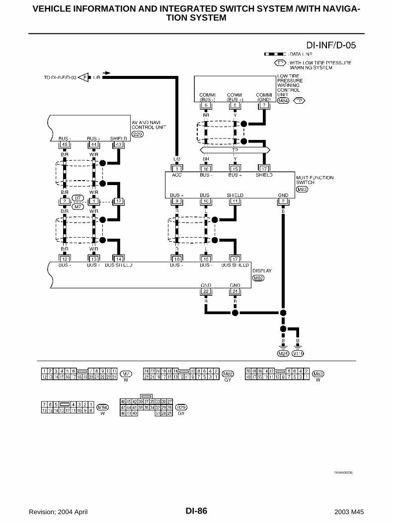
DI-86
VEHICLE INFORMATION AND INTEGRATED SWITCH SYSTEM /WITH NAVIGA-TION SYSTEM
Revision; 2004 April 2003 M45
TKWA0603E

VEHICLE INFORMATION AND INTEGRATED SWITCH SYSTEM /WITH NAVIGA-TION SYSTEM
DI-87
C
D
E
F
G
H
I
J
L
M
A
B
DI
Revision; 2004 April 2003 M45
Terminals and Reference Value for AV and NAVI Control Unit AKS004DQ
Refer to AV-63, "Terminals and Reference Value for AV and NAVI Control unit" .
Terminals and Reference Value for Display AKS004DR
Terminals
Signal
Condition
Reference value(+)
(–)Terminal No.
Wire color
Ignition switch
Operation
1 R/L GroundRGB signal (R: Red)
ONMove to “Screen Adjust-ment” in the check/adjust-ment function.
2 R/W GroundRGB signal (G: Green)
ONMove to “Screen Adjust-ment” in the check/adjust-ment function.
3 B GroundRGB signal (B: Blue)
ONMove to “Screen Adjust-ment” in the check/adjust-ment function.
4 — Ground RGB ground ON — Approx. 0V
5 W GroundHorizontal syn-chronizing signal
ONON screen, the volume can be adjusted.
6 R GroundVertical synchro-nizing signal
ON —
7 G GroundRGB synchroniz-ing signal
ON Press the map switch.
SKIA0165E
SKIA0166E
SKIA0167E
SKIA0163E
SKIA0161E
SKIA0164E

DI-88
VEHICLE INFORMATION AND INTEGRATED SWITCH SYSTEM /WITH NAVIGA-TION SYSTEM
Revision; 2004 April 2003 M45
8 B Ground RGB area signal ONPress the vehicle information switch.
12 B/R GroundCommunication signal (-)
ON —
13 W/R GroundCommunication signal (+)
ON —
14 — — Shield ground — — —
15 L GroundCommunication signal (-)
ON —
16 R GroundCommunication signal (+)
ON —
17 – Ground Shield ground — — —
19 L/B GroundIgnition switch (ACC)
ACC — Battery voltage
21 SBGround Battery power OFF — Battery voltage
23 SB
22 BGround Ground — — —
24 B
Terminals
Signal
Condition
Reference value(+)
(–)Terminal No.
Wire color
Ignition switch
Operation
SKIA0162E
SKIA0176E
SKIA0175E
SKIA0176E
SKIA0175E
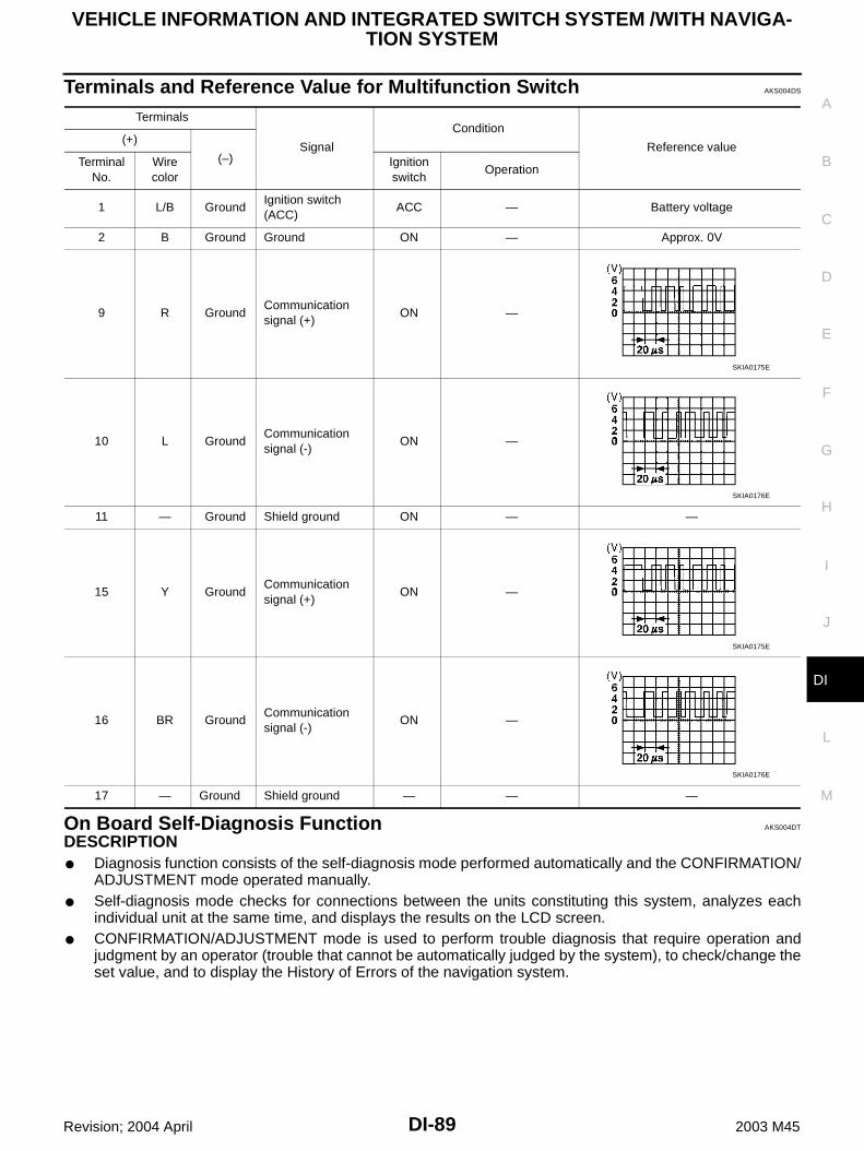
VEHICLE INFORMATION AND INTEGRATED SWITCH SYSTEM /WITH NAVIGA-TION SYSTEM
DI-89
C
D
E
F
G
H
I
J
L
M
A
B
DI
Revision; 2004 April 2003 M45
Terminals and Reference Value for Multifunction Switch AKS004DS
On Board Self-Diagnosis Function AKS004DT
DESCRIPTION Diagnosis function consists of the self-diagnosis mode performed automatically and the CONFIRMATION/
ADJUSTMENT mode operated manually. Self-diagnosis mode checks for connections between the units constituting this system, analyzes each
individual unit at the same time, and displays the results on the LCD screen. CONFIRMATION/ADJUSTMENT mode is used to perform trouble diagnosis that require operation and
judgment by an operator (trouble that cannot be automatically judged by the system), to check/change theset value, and to display the History of Errors of the navigation system.
Terminals
Signal
Condition
Reference value (+)
(–)Terminal No.
Wire color
Ignition switch
Operation
1 L/B GroundIgnition switch (ACC)
ACC — Battery voltage
2 B Ground Ground ON — Approx. 0V
9 R GroundCommunication signal (+)
ON —
10 L GroundCommunication signal (-)
ON —
11 — Ground Shield ground ON — —
15 Y GroundCommunication signal (+)
ON —
16 BR GroundCommunication signal (-)
ON —
17 — Ground Shield ground — — —
SKIA0175E
SKIA0176E
SKIA0175E
SKIA0176E

DI-90
VEHICLE INFORMATION AND INTEGRATED SWITCH SYSTEM /WITH NAVIGA-TION SYSTEM
Revision; 2004 April 2003 M45
DIAGNOSIS ITEM
Self-Diagnosis Mode AKS004DU
Refer to AV-68, "Self-Diagnosis Mode" .
Confirmation/Adjustment Mode AKS004DV
Refer to AV-72, "Confirmation/Adjustment Mode" .
CONSULT-ll Function AKS004DW
Refer to AV-78, "CONSULT-II Function" .
Multifunction Switch Self-Diagnosis Function AKS004DX
It can check ON/OFF operation of each switch in the multifunction switch and diagnose the input signals to therear control switch (audio) and steering switch (audio).
STARTING THE SELF-DIAGNOSIS MODE1. Turn ignition switch from OFF to ACC.2. Within 10 seconds press and hold the function switches “1” and
“6 ”simultaneously for 5 seconds.Then the self-diagnosis operates.
Mode Description
Self-diagnosis
AV and NAVI Control unit diagnosis (DVD-ROM drive will not be diag-nosed when no map DVD-ROM is in it.)
Analyzes connection between the AV and NAVI control unit and the GPS antenna connection between the AV and NAVI control unit and each unit, and operation of each unit.
CONFIRMATION/ADJUSTMENT
Display diagnosisColor tone and shading of the screen can be checked by the display of a color bar and a gray scale.
Vehicle signalsAnalyzes the following vehicle signals: Vehicle speed signal, parking brake signal, light signal, ignition switch signal, and reverse signal.
Speaker Test Checks the connection of each speaker using a test tone.
Auto Climate Control Turns all A/C screens on display and A/C switch indicator lamp on.
Navigation
Display Longitude & Latitude
Display the map.Use the joystick to adjust position. Longitude and latitude will be displayed.
Speed Calibration
Under ordinary conditions, the navigation system distance measuring func-tion will automatically compensate for minute decreases in wheel and tire diameter caused by tire wear or low pressure.Speed calibration immediately restores system accuracy in cases such as when distance calibration is needed because of the use of tire chains in inclement weather.
Angle AdjustmentCorrects difference between actual turning angle of a vehicle and turning angle of the car mark on the display.
Initialize LocationThis mode is for initializing the current location. Use when the vehicle is transported a long distance on a trailer, etc.
History of ErrorsDiagnosis results previously stored in the memory (before turning ignition switch ON) are displayed in this mode. Time and location when/where the errors occurred are also displayed.
Rear View Camera Changes position of the aiming line overlapped on the rear view image.
SKIA0609E

VEHICLE INFORMATION AND INTEGRATED SWITCH SYSTEM /WITH NAVIGA-TION SYSTEM
DI-91
C
D
E
F
G
H
I
J
L
M
A
B
DI
Revision; 2004 April 2003 M45
EXITING THE SELF-DIAGNOSIS MODE Turn ignition switch OFF, or press and hold the function switches “1” and “6” simultaneously for 5 seconds.
Then the self-diagnosis ends.
DIAGNOSIS FUNCTION It can illuminate all the indicators (LED) in the multifunction switch. It can check for continuity of the switches by sounding the buzzer when the multifunction switch is
pressed. It can check for continuity of harness between multifunction switch and rear control switch (audio), or
steering switch (audio).NOTE:When it check continuity of harness between multifunction switch and rear control switch (audio), rearcontrol cancel switch is OFF position.
Power Supply and Ground Circuit Check for AV and NAVI Control Unit AKS004DY
Refer to AV-82, "Power Supply and Ground Circuit Check" .

DI-92
VEHICLE INFORMATION AND INTEGRATED SWITCH SYSTEM /WITH NAVIGA-TION SYSTEM
Revision; 2004 April 2003 M45
Power Supply and Ground Circuit Inspection for Display AKS004DZ
1. CHECK FUSES
Check 15A fuse [No. 52, located in fuse, fusible link and relay block (J/B)] is blown.OK or NGOK >> GO TO 2.NG >> If fuse is blown, be sure to eliminate cause of malfunction before installing new fuse. Refer to PG-
2, "POWER SUPPLY ROUTING" .
2. CHECK POWER SUPPLY CIRCUIT
1. Disconnect display connector. 2. Check voltage between display and ground.
OK or NGOK >> GO TO 3.NG >> Check harness for open or short between display and fuse.
3. CHECK GROUND CIRCUIT
1. Turn ignition switch OFF.2. Check continuity between display and ground.
OK or NGOK >> Inspection end.NG >> Repair harness or connector.
Terminals Ignition switch position
(+)
(–) OFF ACC ONConnector
Terminal(Wire color)
M82
19 (L/B) Ground 0VBattery voltage
Battery voltage
21 (SB) GroundBattery voltage
Battery voltage
Battery voltage
23 (SB) GroundBattery voltage
Battery voltage
Battery voltage
SKIA0552E
Terminals
Continuity(+)
(–)Connector
Terminal(Wire color)
M82 22 (B) Ground Yes
M82 24 (B) Ground Yes
SKIA0553E

VEHICLE INFORMATION AND INTEGRATED SWITCH SYSTEM /WITH NAVIGA-TION SYSTEM
DI-93
C
D
E
F
G
H
I
J
L
M
A
B
DI
Revision; 2004 April 2003 M45
Power Supply and Ground Circuit Inspection for Multifunction Switch AKS004E0
1. CHECK POWER SUPPLY CIRCUIT
1. Disconnect multifunction switch connector.2. Check voltage between multifunction switch and ground.
OK or NGOK >> GO TO 2.NG >> Check harness for open or short between multifunction switch and fuse.
2. CHECK GROUND CIRCUIT
1. Turn ignition switch OFF.2. Check continuity between multifunction switch harness connec-
tor M83 terminal 2 (B) and ground.
OK or NGOK >> Inspection end.NG >> Repair harness or connector.
No Fuel Information Is Displayed/No Warning Message Is Displayed AKS004E1
1. CHECK HARNESS
1. Disconnect connectors of combination meter, BCM, and AV and NAVI control unit.2. Check continuity between AV and NAVI control unit and combination meter.
3. Check continuity between AV and NAVI control unit and ground.
OK or NGOK >> GO TO 2.NG >> Repair harness or connector.
Terminals Ignition switch position
(+)
(–) OFF ACC ONConnector
Terminal(Wire color)
M83 1 (L/B) Ground 0VBattery voltage
Battery voltage
SKIA0534E
Continuity should exist.
SKIA0535E
Terminals
ContinuityAV and NAVI control unit (+) Combination meter (–)
ConnectorTerminal
(Wire color)Connector
Terminal (Wire color)
B29 33 (LG) M42 56 (LG) Yes
B29 32 (PU) M42 57 (PU) Yes
Terminals
ContinuityAV and NAVI control unit (+)(–)
Connector Terminal (Wire color)
B2933 (LG)
Ground No32 (PU)
SKIA4205E

DI-94
VEHICLE INFORMATION AND INTEGRATED SWITCH SYSTEM /WITH NAVIGA-TION SYSTEM
Revision; 2004 April 2003 M45
2. CHECK COMMUNICATION SIGNAL (AV-ME)
1. Connect connectors of combination meter, BCM, and AV and NAVI control unit.2. Turn ignition switch ON.3. Check the signal between AV and NAVI control unit harness
connector B29 terminal 33 (LG) and ground with CONSULT-ll oroscilloscope.
OK or NGOK >> GO TO 3.NG >> Replace AV and NAVI control unit.
3. CHECK COMMUNICATION SIGNAL (ME–AV)
1. Turn ignition switch to ON and display “VEHICLE ELECTRONIC SYSTEMS”screen.2. Check voltage signal between AV and NAVI control unit harness
connector B29 terminal 32 (PU) and ground with CONSULT-ll oroscilloscope.
OK or NGOK >> Replace AV and NAVI control unit.NG >> Replace combination meter.
Vehicle Condition Setting Is Not Possible. AKS004E2
1. CHECK HARNESS
1. Disconnect connectors of combination meter, BCM, and AV and NAVI control unit.2. Check continuity AV and NAVI control unit and BCM.
3. Check continuity between AV and NAVI control unit and ground.
OK or NGOK >> GO TO 2.NG >> Repair harness or connector.
33 (LG) - Ground : Refer to AV-63, "Terminals and Reference Value for AV and NAVI Control unit" .
SKIA3534E
32 (PU) - Ground : Refer to AV-63, "Terminals and Reference Value for AV and NAVI Control unit" .
SKIA3535E
Terminals
ContinuityAV and NAVI control unit (+) BCM (–)
ConnectorTerminal
(Wire color)Connector
Terminal (Wire color)
B29 33 (LG) M4 31 (LG) Yes
B29 32 (PU) M4 30 (PU) Yes
Terminals
ContinuityAV and NAVI control unit (+)(–)
Connector Terminal (Wire color)
B2933 (LG)
Ground No32 (PU)
SKIA3536E
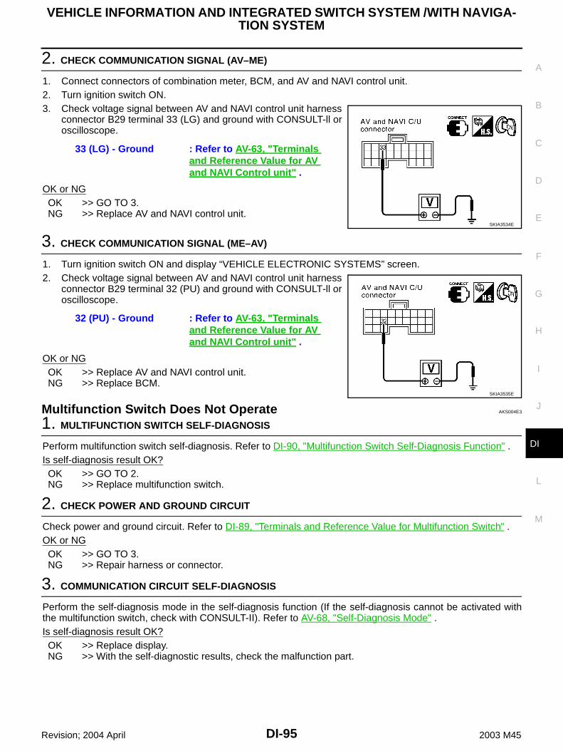
VEHICLE INFORMATION AND INTEGRATED SWITCH SYSTEM /WITH NAVIGA-TION SYSTEM
DI-95
C
D
E
F
G
H
I
J
L
M
A
B
DI
Revision; 2004 April 2003 M45
2. CHECK COMMUNICATION SIGNAL (AV–ME)
1. Connect connectors of combination meter, BCM, and AV and NAVI control unit.2. Turn ignition switch ON.3. Check voltage signal between AV and NAVI control unit harness
connector B29 terminal 33 (LG) and ground with CONSULT-ll oroscilloscope.
OK or NGOK >> GO TO 3.NG >> Replace AV and NAVI control unit.
3. CHECK COMMUNICATION SIGNAL (ME–AV)
1. Turn ignition switch ON and display “VEHICLE ELECTRONIC SYSTEMS” screen.2. Check voltage signal between AV and NAVI control unit harness
connector B29 terminal 32 (PU) and ground with CONSULT-ll oroscilloscope.
OK or NGOK >> Replace AV and NAVI control unit.NG >> Replace BCM.
Multifunction Switch Does Not Operate AKS004E3
1. MULTIFUNCTION SWITCH SELF-DIAGNOSIS
Perform multifunction switch self-diagnosis. Refer to DI-90, "Multifunction Switch Self-Diagnosis Function" .Is self-diagnosis result OK?OK >> GO TO 2.NG >> Replace multifunction switch.
2. CHECK POWER AND GROUND CIRCUIT
Check power and ground circuit. Refer to DI-89, "Terminals and Reference Value for Multifunction Switch" .OK or NGOK >> GO TO 3.NG >> Repair harness or connector.
3. COMMUNICATION CIRCUIT SELF-DIAGNOSIS
Perform the self-diagnosis mode in the self-diagnosis function (If the self-diagnosis cannot be activated withthe multifunction switch, check with CONSULT-II). Refer to AV-68, "Self-Diagnosis Mode" .Is self-diagnosis result OK?OK >> Replace display.NG >> With the self-diagnostic results, check the malfunction part.
33 (LG) - Ground : Refer to AV-63, "Terminals and Reference Value for AV and NAVI Control unit" .
SKIA3534E
32 (PU) - Ground : Refer to AV-63, "Terminals and Reference Value for AV and NAVI Control unit" .
SKIA3535E

DI-96
VEHICLE INFORMATION AND INTEGRATED SWITCH SYSTEM /WITH NAVIGA-TION SYSTEM
Revision; 2004 April 2003 M45
Multifunction Switch Indicator Does Not illuminate AKS004E4
1. MULTIFUNCTION SWITCH SELF-DIAGNOSIS
Perform the multifunction switch self-diagnosis. Refer to DI-90, "Multifunction Switch Self-Diagnosis Function".Is the self-diagnosis result OK?OK >> Replace switch of the malfunctioning indicator.NG >> Replace multifunction switch.
Removal and Installation of Display AKS004E5
REMOVAL1. Remove the cluster lid C. Refer to IP-10, "INSTRUMENT
PANEL ASSEMBLY" 2. Remove the screws (4), and remove the display.
3. Remove screws (4), and remove bracket.
INSTALLATIONInstall in the reverse order of removal.
PKIA1669E
PKIA1670E

VEHICLE INFORMATION AND INTEGRATED SWITCH SYSTEM /WITH NAVIGA-TION SYSTEM
DI-97
C
D
E
F
G
H
I
J
L
M
A
B
DI
Revision; 2004 April 2003 M45
Disassembly and Assembly for Multifunction Switch AKS004E6
1. Remove the screw (8)2. Remove the switches.
1. Multifunction switch 2. Escutcheon 3. Hazard switch
4. Defroster, rear defogger switch 5. Function switch 6. Function switch
7. Function switch 8. TAPE and DISC switch 9. A/C switch
10. Escutcheon 11. AM and FM switch 12. Escutcheon
13. Switch assembly 14. Escutcheon 15. Cluster lid C
PKIA1671E

DI-98
VEHICLE INFORMATION AND INTEGRATED SWITCH SYSTEM /WITH NAVIGA-TION SYSTEM
Revision; 2004 April 2003 M45
Removal and Installation of AV and NAVI Control Unit AKS004E7
REMOVAL1. Remove the trunk front finisher. Refer to EI-41, "TRUNK ROOM
TRIM & TRUNK LID FINISHER" .2. Remove the screws (4) and remove the AV and NAVI control
unit.
INSTALLATIONInstall in the reverse order of removal.
SKIA3581E

VEHICLE INFORMATION AND INTEGRATED SWITCH SYSTEM /WITHOUT NAVIGATION SYSTEM
DI-99
C
D
E
F
G
H
I
J
L
M
A
B
DI
Revision; 2004 April 2003 M45
VEHICLE INFORMATION AND INTEGRATED SWITCH SYSTEM /WITHOUT NAVI-GATION SYSTEM PFP:28395
System Description AKS004OH
INTEGRATED SWITCH SYSTEMUsing the multifunction switch at the center of the instrument panel, the controls of the following systems arecentralized: Auto A/C system Vehicle information system Audio system Hazard switchThe multifunction switch can operate and check the vehicle condition and each setting (vehicle electrical sys-tem).
PRECAUTION OF LCD MONITOR When passenger compartment temperature is low, the LCD monitor sometimes dims because of the
brightness of the back light (small fluorescent light) integrated into the LCD monitor decrease. In this case,the refreshing rate of the picture also becomes low because of the low response of the LCD monitor.When passenger compartment becomes warm, however, the LCD recovers the normal display.
Sometimes, black or bright dots peculiar to LCD monitor can be seen on the display. Back light sometimes flickers or darkens according to the total consumption hours and the number of ON
and OFF switching. In this case, the back light should be replaced. (LCD monitor assembly).
POWER SUPPLY AND GROUNDPower Is Supplied At All Times through 15A fuse [No. 52, located in fuse, fusible link and relay block (J/B)] to AV control unit terminals 2 and 3, and to display terminals 21 and 23.
When Ignition Switch is in ACC or ON Position, Power is Supplied through 10A fuse [No. 21, located in fuse block (J/B) NO. 1] to AV control unit terminal 6 to display terminal 19, and to multifunction switch terminal 1.
When Ignition Switch is in ON or START Position, Power is Supplied through 10A fuse [No. 1, located in fuse block (J/B) NO. 1] to AV control unit terminal 27.
Ground is Supplied to AV control unit terminals 1 and 4 through body grounds M25 and M115, and to multifunction switch terminal 2 and to display terminals 22 and 24 through grounds M24 and M114.
AV COMMUNICATION LINEAV control unit is connected to the following units by AV communication line. Each unit transmits/receives datawith AV communication line. Display Multifunction switch Audio unit BOSE speaker amp.(audio amp.) Rear view camera control unit Low tire pressure warning control unit

DI-100
VEHICLE INFORMATION AND INTEGRATED SWITCH SYSTEM /WITHOUT NAVIGATION SYSTEM
Revision; 2004 April 2003 M45
Voice activated control module
VEHICLE INFORMATION SYSTEM AV control unit is received vehicle information system of signals from combination meter. AV control unit is communicating with BCM and combination meter.1. Press “INFO” switch to display vehicle information display.
2. Select “Trip Computer”, “Fuel Economy”, “Maintenance” or “TirePressure”.
*: Maintenance information displays the change cycle of engine oil, oil filter and tire on LCD monitor depending on the driving dis-tance specified by a driver or a technician.
SKIA0600E
SKIA0599E
Display items Display/Setting contents
Trip Computer
Elapsed time
Driving distance
Average speed
Fuel Economy
Average fuel economy (MPG)
Distance to empty (Miles)
Fuel economy (MPG)
Fuel economy record
Maintenance (with Maintenance information*)
Maintenance intervals of engine oil and setting of oil change cycle
Maintenance intervals of oil filter and setting of filter replacement cycle
Maintenance intervals of tire and setting of tire replacement cycle
Tire Pressure Tire pressure information

VEHICLE INFORMATION AND INTEGRATED SWITCH SYSTEM /WITHOUT NAVIGATION SYSTEM
DI-101
C
D
E
F
G
H
I
J
L
M
A
B
DI
Revision; 2004 April 2003 M45
Trip Computer Information1. Select “Trip Computer”.2. Elapsed Time, Driving Distance and Average Speed are dis-
played as Trip Computer information.
Fuel Economy Information1. Select “Fuel Economy”.2. Average Fuel Economy, Distance to Empty, Fuel Economy are
displayed as Fuel Economy information.
3. Select “Fuel Economy Record”. The average fuel consumptionhistory will be displayed in graph along with the average for theprevious Reset – to – Reset period.
Maintenance Information1. Select “Maintenance”.2. Engine Oil, Oil Filter and Tire Rotation are displayed as Mainte-
nance information.
SKIA0601E
SKIA0602E
SKIA0603E
SKIA0604E

DI-102
VEHICLE INFORMATION AND INTEGRATED SWITCH SYSTEM /WITHOUT NAVIGATION SYSTEM
Revision; 2004 April 2003 M45
Tire Pressure Information1. Select “Tire Pressure”.2. Tire pressure displayed as Tire Pressure information.
NOTE: When air pressure becomes 180kPa (1.8kg/cm2 , 26psi) or
less, “LOW PRESSURE” warning is indicated.
When air pressure becomes 70kPa (0.7kg/cm2 , 10psi) orless, “FLAT TIRE” warning is indicated.
When pressure is not detected or tire pressure system hasmalfunction “** psi” is indicated.
Indication with yellow frame for the malfunctioning tire.
SETTING OF VEHICLE STATUS Setting of electric status can be changed by multifunction switch.The signal is sent to BCM through AV
control unit to change vehicle electric system setting. AV control unit is communicating with BCM and combination meter.1. Press “SETTING” switch to display vehicle information display.
2. Select “Vehicle Electronic System”.
3. Select a vehicle status shown on the display.
SKIA3737E
SKIA0605E
SKIA0606E
SKIA0608E

VEHICLE INFORMATION AND INTEGRATED SWITCH SYSTEM /WITHOUT NAVIGATION SYSTEM
DI-103
C
D
E
F
G
H
I
J
L
M
A
B
DI
Revision; 2004 April 2003 M45
Adjustable vehicle status Lift Steering Column When Exiting Vehicle Adjust Driver Seat When Exiting Vehicle Illuminate Interior When Unlocking Vehicle Interior Lights Off Delay
Sensitivity of Automatic Headlights Automatic Headlights Off Delay Key Remote Response - Horn/Lights Remote Custom Settings
Return All Settings to Default
SKIA0610E
SKIA0611E
SKIA0612E

DI-104
VEHICLE INFORMATION AND INTEGRATED SWITCH SYSTEM /WITHOUT NAVIGATION SYSTEM
Revision; 2004 April 2003 M45
Adjustable vehicle statusSetting items Setting variations Initial setting Operation
Lift Steering Column When Exiting Vehicle ON/OFF ON
The steering column automatically tilts up when the driver gets out, and returns to the original position when the driver gets on.
When driver door is closed and key removed from ignition key cylinder, the steering column tilts up.
When driver door is open and key is turned to OFF, the steering column tilts up.
Adjust Driver Seat When Exiting Vehicle ON/OFF ONThe driver’s seat automatically slides backward when the driver gets out, and returns to the origi-nal position when the driver gets on.
Illuminate Interior When Unlocking Vehicle ON/OFF ONThe interior room lamps are illuminate automati-cally when the door unlocked with key or key fob.
Interior Lights Off Delay OFF/15/30/45 sec. 30 sec.Interior room lamp timer period can be changed in this mode. Selects interior room lamp timer.
Sensitivity of Automatic Headlights 1/2/3/4 3 Sensitivity of auto light sensor can be adjusted.
Automatic Headlights Off DelayOFF/20/45/90/120/
150/180 sec.45 sec.
Auto light delay off timer period can be changed in this mode. Selects auto light delay off timer.
Key Remote Response - Horn/Lights
Hazard indicators only
/Hazard indicators and horn
Hazard indi-cators only
Hazard indicators Only:
Lock operation: The hazard warning lamp flash twice when lock the doors with key fob.
Unlock operation: No response.
Hazard indicators and horn:
Lock operation: The hazard warning lamp flash twice and horn sounds once when lock the doors with key fob.
Unlock operation; The hazard warning lamp flash once when unlock the doors with key fob.
Remote Custom Settings ON/OFF ON
The driving position -seat and steering column- and the audio setting -current source and radio station presets- are set to the same condition you made last time by identifying the key fob ID.This function operates when unlock the doors by using the key fob.
NOTE:It is necessary to memorize the driving position before using this function.
Return All Settings to Default None NoneIf this key is selected, all vehicle electronic sys-tems setting are return to default.

VEHICLE INFORMATION AND INTEGRATED SWITCH SYSTEM /WITHOUT NAVIGATION SYSTEM
DI-105
C
D
E
F
G
H
I
J
L
M
A
B
DI
Revision; 2004 April 2003 M45
WARNING INDICATIONSWhen combination meter receives warning signal from some control units or sensors, then combination meterwarning lamp is illuminated.Then combination meter sends warning signal to AV control unit to display warning indications on the screen.
Warning indicatorsWarning lamps in instrument panel
Warning detection and cancel conditions Cases of malfunction
MALFUNCTIONSERVICE ENGINE SOON
Detection conditionWarning lamp ON signal is detected while engine is running.
ECM malfunction
Cancel conditionWarning lamp OFF signal is detected.
ENGINE OIL PRES-SURE
Engine oil pressure
Detection condition
Warning lamp ON signal is detected for at least approx. 5 sec-onds while engine is running.[Engine oil pressure: MAX. approx.
29kPa (0.3kg/cm2 , 4psi)] Engine oil pressure decreases
Cancel condition
Warning lamp OFF signal is detected. [Engine oil pressure:
MIN. approx. 29kPa (0.3kg/cm2 , 4psi)]
SUPPLEMENTAL AIR BAG
Air bag
Detection condition
Warning lamp ON signal is detected for at least approx. 10 seconds after ignition switch is turned ON.
SRS air bag system mal-function
Cancel conditionWarning lamp OFF signal is detected.
LOW BRAKE FLUID Brake
Detection conditionWarning lamp ON signal (fluid level) is detected.
Low brake fluid level
Cancel conditionWarning lamp OFF signal is detected.
OVERHEATING –
Detection conditionEngine coolant temperature as being approx. 119°C (246°F) min. Engine cooling system
malfunctionCancel condition
Engine coolant temperature as being approx. 105°C (221°F) max.
CHARGE Charge
Detection conditionWarning lamp ON signal is detected while engine is running. Charging system malfunction Charging system mal-
function
Cancel conditionWarning lamp OFF signal is detected.
LOW WASHER FLUID –Detection condition
Washer liquid level falls below
approx. 0.4 .(7/8US qt, 3/4Imp pt) Low washer liquid level
Cancel condition Except above condition.
LOW FUEL Fuel level
Detection condition
After warning lamp ON signal is detected, vehicle is driven for over specified distance. (Fuel level:
Approx. 14.0 14-3/4US qt,12-3/8Imp pt)
Low fuel level
Cancel conditionWarning lamp OFF signal is detected.
PARKING BRAKE Brake
Detection conditionParking brake ON signal is detected while vehicle is running [approx. 5km/h (3MPH) or faster]. Parking brake remains
engaged.
Cancel conditionVehicle is stopped, or parking brake OFF signal is detected.
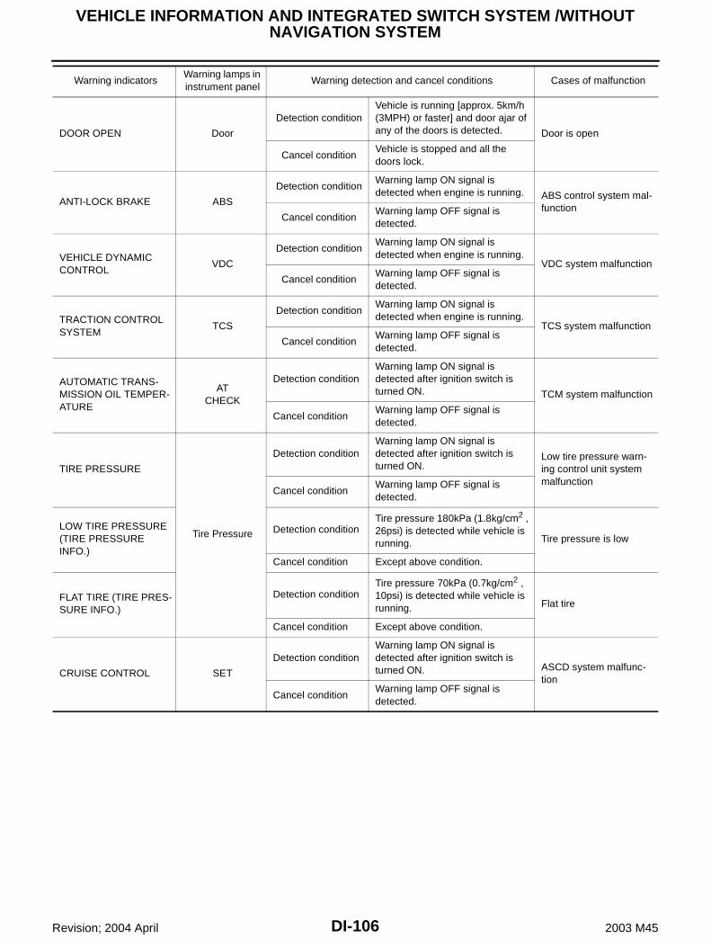
DI-106
VEHICLE INFORMATION AND INTEGRATED SWITCH SYSTEM /WITHOUT NAVIGATION SYSTEM
Revision; 2004 April 2003 M45
DOOR OPEN Door
Detection conditionVehicle is running [approx. 5km/h (3MPH) or faster] and door ajar of any of the doors is detected. Door is open
Cancel conditionVehicle is stopped and all the doors lock.
ANTI-LOCK BRAKE ABS
Detection conditionWarning lamp ON signal is detected when engine is running. ABS control system mal-
functionCancel condition
Warning lamp OFF signal is detected.
VEHICLE DYNAMIC CONTROL
VDC
Detection conditionWarning lamp ON signal is detected when engine is running.
VDC system malfunction
Cancel conditionWarning lamp OFF signal is detected.
TRACTION CONTROL SYSTEM
TCS
Detection conditionWarning lamp ON signal is detected when engine is running.
TCS system malfunction
Cancel conditionWarning lamp OFF signal is detected.
AUTOMATIC TRANS-MISSION OIL TEMPER-ATURE
AT CHECK
Detection conditionWarning lamp ON signal is detected after ignition switch is turned ON. TCM system malfunction
Cancel conditionWarning lamp OFF signal is detected.
TIRE PRESSURE
Tire Pressure
Detection conditionWarning lamp ON signal is detected after ignition switch is turned ON.
Low tire pressure warn-ing control unit system malfunction
Cancel conditionWarning lamp OFF signal is detected.
LOW TIRE PRESSURE (TIRE PRESSURE INFO.)
Detection conditionTire pressure 180kPa (1.8kg/cm2 , 26psi) is detected while vehicle is running. Tire pressure is low
Cancel condition Except above condition.
FLAT TIRE (TIRE PRES-SURE INFO.)
Detection conditionTire pressure 70kPa (0.7kg/cm2 , 10psi) is detected while vehicle is running. Flat tire
Cancel condition Except above condition.
CRUISE CONTROL SET
Detection conditionWarning lamp ON signal is detected after ignition switch is turned ON. ASCD system malfunc-
tion
Cancel conditionWarning lamp OFF signal is detected.
Warning indicatorsWarning lamps in instrument panel
Warning detection and cancel conditions Cases of malfunction

VEHICLE INFORMATION AND INTEGRATED SWITCH SYSTEM /WITHOUT NAVIGATION SYSTEM
DI-107
C
D
E
F
G
H
I
J
L
M
A
B
DI
Revision; 2004 April 2003 M45
Precautions for AV Control Unit Replacement AKS003ZR
The AV control unit has the following information stored in its memory. Record the memory contents beforereplacing the control unit, and input them in the new unit as necessary.
NOTE:Only removing the battery does not erase the memory.
Component Parts and Harness Connector Location AKS003ZS
<FM·AM> Preset frequency Area for indicating station, selection of overlapped stations
<CD> Program status<Sound quality> Volume balance memory set values
Equalizer memory set values<Image quality> Brightness of light when ON/OFF
Dimming switching Display color switching
SKIA9346E
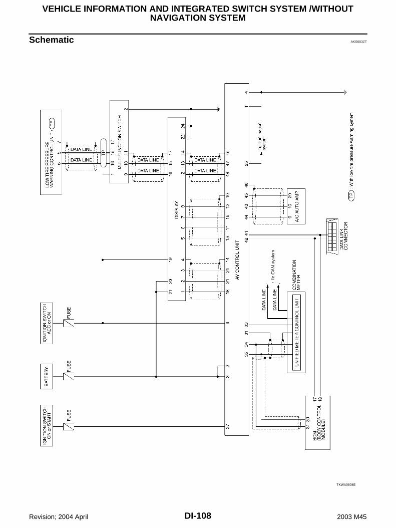
DI-108
VEHICLE INFORMATION AND INTEGRATED SWITCH SYSTEM /WITHOUT NAVIGATION SYSTEM
Revision; 2004 April 2003 M45
Schematic AKS003ZT
TKWA0604E

VEHICLE INFORMATION AND INTEGRATED SWITCH SYSTEM /WITHOUT NAVIGATION SYSTEM
DI-109
C
D
E
F
G
H
I
J
L
M
A
B
DI
Revision; 2004 April 2003 M45
Wiring Diagram — INF/D — AKS003ZU
TKWA0605E

DI-110
VEHICLE INFORMATION AND INTEGRATED SWITCH SYSTEM /WITHOUT NAVIGATION SYSTEM
Revision; 2004 April 2003 M45
TKWA0606E

VEHICLE INFORMATION AND INTEGRATED SWITCH SYSTEM /WITHOUT NAVIGATION SYSTEM
DI-111
C
D
E
F
G
H
I
J
L
M
A
B
DI
Revision; 2004 April 2003 M45
TKWA0607E

DI-112
VEHICLE INFORMATION AND INTEGRATED SWITCH SYSTEM /WITHOUT NAVIGATION SYSTEM
Revision; 2004 April 2003 M45
TKWA0608E

VEHICLE INFORMATION AND INTEGRATED SWITCH SYSTEM /WITHOUT NAVIGATION SYSTEM
DI-113
C
D
E
F
G
H
I
J
L
M
A
B
DI
Revision; 2004 April 2003 M45
TKWA0609E
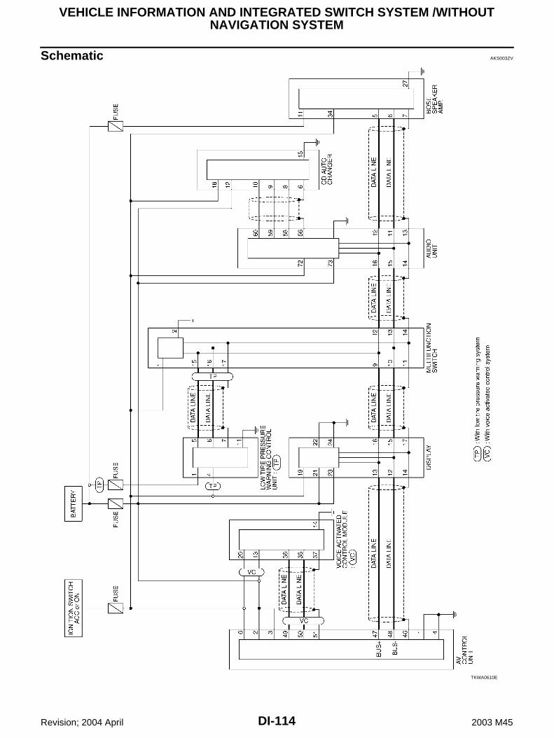
DI-114
VEHICLE INFORMATION AND INTEGRATED SWITCH SYSTEM /WITHOUT NAVIGATION SYSTEM
Revision; 2004 April 2003 M45
Schematic AKS003ZV
TKWA0610E

VEHICLE INFORMATION AND INTEGRATED SWITCH SYSTEM /WITHOUT NAVIGATION SYSTEM
DI-115
C
D
E
F
G
H
I
J
L
M
A
B
DI
Revision; 2004 April 2003 M45
Wiring Diagram — COMM — AKS003ZW
TKWA0615E

DI-116
VEHICLE INFORMATION AND INTEGRATED SWITCH SYSTEM /WITHOUT NAVIGATION SYSTEM
Revision; 2004 April 2003 M45
TKWA0616E

VEHICLE INFORMATION AND INTEGRATED SWITCH SYSTEM /WITHOUT NAVIGATION SYSTEM
DI-117
C
D
E
F
G
H
I
J
L
M
A
B
DI
Revision; 2004 April 2003 M45
TKWA0617E

DI-118
VEHICLE INFORMATION AND INTEGRATED SWITCH SYSTEM /WITHOUT NAVIGATION SYSTEM
Revision; 2004 April 2003 M45
TKWA0618E

VEHICLE INFORMATION AND INTEGRATED SWITCH SYSTEM /WITHOUT NAVIGATION SYSTEM
DI-119
C
D
E
F
G
H
I
J
L
M
A
B
DI
Revision; 2004 April 2003 M45
Terminals and Reference Value for AV Control Unit AKS003ZX
Terminals
SignalSignal input/output
Condition
Reference valueExample of symptom
(+)
(–)Terminal No.
Wire color
Igni-tion
switchOperation
1 B Ground Ground — ON — Approx. 0V —
2 SBGround Battery Input OFF — Battery voltage
System does not work properly.3 SB
4 B Ground Ground — ON — Approx. 0V —
6 L/B GroundIgnition switch (ACC)
Input ACC — Battery voltageSystem does
not work properly.
10 — —Shield
Ground— — — — —
11 R 10
Vertical synchroniz-
ing (VP) signal
Input ON —Superim-
posed screen is rolling.
12 B 10RGB area (YS) signal
Output ONPress the
“info”switch.RGB screen is not shown.
13 W 10
Horizontal synchroniz-
ing (HP) signal
Input ON
Adjust sound vol-ume while rear view screen is
shown.
RGB screen is not shown.
14 — GroundRGB
ground— — — — —
15 G 10RGB syn-chronizing
signalOutput ON
Press the “MAP” switch.
RGB screen is rolling.
18 R/L 14RGB sig-
nal (R: red)Output ON
Select “SCREEN ADJUSTMENT” of CONFIRMA-TION/ADJUST-MENT function.
RGB screen looks bluish.
SKIA0161E
SKIA0162E
SKIA0163E
SKIA0164E
SKIA0165E
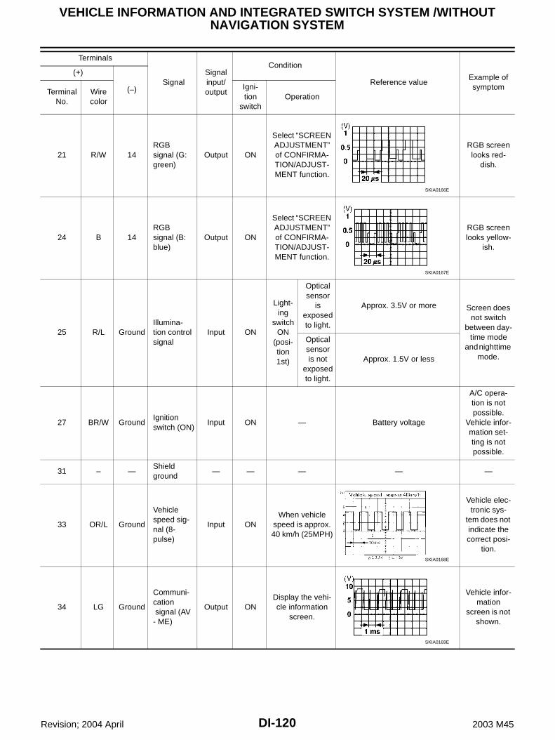
DI-120
VEHICLE INFORMATION AND INTEGRATED SWITCH SYSTEM /WITHOUT NAVIGATION SYSTEM
Revision; 2004 April 2003 M45
21 R/W 14RGB signal (G: green)
Output ON
Select “SCREEN ADJUSTMENT” of CONFIRMA-TION/ADJUST-MENT function.
RGB screen looks red-
dish.
24 B 14RGB signal (B: blue)
Output ON
Select “SCREEN ADJUSTMENT” of CONFIRMA-TION/ADJUST-MENT function.
RGB screen looks yellow-
ish.
25 R/L GroundIllumina-tion control signal
Input ON
Light-ing
switch ON
(posi-tion 1st)
Optical sensor
is exposed to light.
Approx. 3.5V or more Screen does not switch
between day-time mode
and nighttime mode.
Optical sensor is not
exposed to light.
Approx. 1.5V or less
27 BR/W GroundIgnition switch (ON)
Input ON — Battery voltage
A/C opera-tion is not possible.
Vehicle infor-mation set-ting is not possible.
31 – —Shield ground
— — — — —
33 OR/L Ground
Vehicle speed sig-nal (8-pulse)
Input ONWhen vehicle
speed is approx. 40 km/h (25MPH)
Vehicle elec-tronic sys-
tem does not indicate the correct posi-
tion.
34 LG Ground
Communi-cation signal (AV - ME)
Output ONDisplay the vehi-cle information
screen.
Vehicle infor-mation
screen is not shown.
Terminals
SignalSignal input/output
Condition
Reference valueExample of symptom
(+)
(–)Terminal No.
Wire color
Igni-tion
switchOperation
SKIA0166E
SKIA0167E
SKIA0168E
SKIA0169E

VEHICLE INFORMATION AND INTEGRATED SWITCH SYSTEM /WITHOUT NAVIGATION SYSTEM
DI-121
C
D
E
F
G
H
I
J
L
M
A
B
DI
Revision; 2004 April 2003 M45
35 PU Ground
Communi-cation signal (ME - AV)
Input ON
Perform various settings on the vehicle informa-
tion screen.
Vehicle infor-mation
screen is not shown.
40 — —Shield ground
— — — — —
41 P Ground
CONSULT-II communi-cation signal (AV - CN)
Output ONPerform CON-
SULT-II.
Diagnosis with CON-
SULT-II is not possible.
42 BR/Y Ground
CONSULT-II communi-cation signal (CN - AV)
Input ONPerform CON-
SULT-II.
Diagnosis with CON-
SULT-II is not possible.
43 L Ground
A/C com-munication signal (AC-AV)
Input ON—
A/C status is not indicated
correctly.
44 L/W Ground
A/C com-munication signal (AV-AC)
Output ON —A/C opera-tion is not possible.
45 L/R GroundA/C clock signal
Input ON —A/C status is not indicated
correctly.
46 — —Shield ground
— — — — —
Terminals
SignalSignal input/output
Condition
Reference valueExample of symptom
(+)
(–)Terminal No.
Wire color
Igni-tion
switchOperation
SKIA0170E
SKIA0169E
SKIA0170E
SKIA0173E
SKIA0172E
SKIA0174E

DI-122
VEHICLE INFORMATION AND INTEGRATED SWITCH SYSTEM /WITHOUT NAVIGATION SYSTEM
Revision; 2004 April 2003 M45
Terminals and Reference Value for Display AKS003ZY
47 W/R GroundCommuni-cation sig-nal (+)
Input/output
ON —System does
not work properly.
48 B/R GroundCommuni-cation sig-nal (-)
Input/output
ON —System does
not work properly.
Terminals
SignalSignal input/output
Condition
Reference valueExample of symptom
(+)
(–)Terminal No.
Wire color
Igni-tion
switchOperation
SKIA0175E
SKIA0176E
Terminals
Signal
Condition
Reference value(+)
(–)Terminal No.
Wire color
Ignition switch
Operation
1 R/L GroundRGB signal (R: Red)
ONMove to “Screen Adjust-ment” in the check/adjustment function.
2 R/W GroundRGB signal (G: Green)
ONMove to “Screen Adjust-ment” in the check/adjustment function.
3 B GroundRGB signal (B: Blue)
ONMove to “Screen Adjust-ment” in the check/adjustment function.
4 — Ground RGB ground ON — Approx. 0V
5 W GroundHorizontal syn-chronizing signal
ONON screen, the volume can be adjusted.
SKIA0165E
SKIA0166E
SKIA0167E
SKIA0163E

VEHICLE INFORMATION AND INTEGRATED SWITCH SYSTEM /WITHOUT NAVIGATION SYSTEM
DI-123
C
D
E
F
G
H
I
J
L
M
A
B
DI
Revision; 2004 April 2003 M45
6 R GroundVertical synchro-nizing signal
ON —
7 G GroundRGB synchroniz-ing signal
ON Press the map switch.
8 B Ground RGB area signal ONPress the vehicle information switch.
12 B/R GroundCommunication signal (-)
ON —
13 W/R GroundCommunication signal (+)
ON —
14 — — Shield ground — — —
15 L GroundCommunication signal (-)
ON —
16 R GroundCommunication signal (+)
ON —
17 — — Shield ground — — —
Terminals
Signal
Condition
Reference value(+)
(–)Terminal No.
Wire color
Ignition switch
Operation
SKIA0161E
SKIA0164E
SKIA0162E
SKIA0176E
SKIA0175E
SKIA0176E
SKIA0175E

DI-124
VEHICLE INFORMATION AND INTEGRATED SWITCH SYSTEM /WITHOUT NAVIGATION SYSTEM
Revision; 2004 April 2003 M45
19 L/B GroundIgnition switch (ACC)
ACC — Battery voltage
21 SBGround Battery power OFF — Battery voltage
23 SB
22 BGround Ground — — —
24 B
Terminals
Signal
Condition
Reference value(+)
(–)Terminal No.
Wire color
Ignition switch
Operation

VEHICLE INFORMATION AND INTEGRATED SWITCH SYSTEM /WITHOUT NAVIGATION SYSTEM
DI-125
C
D
E
F
G
H
I
J
L
M
A
B
DI
Revision; 2004 April 2003 M45
Terminals and Reference Value for Multifunction Switch AKS003ZZ
Terminals
Signal
Condition
Reference value (+)
(–)Terminal No.
Wire color
Ignition switch
Operation
1 L/B GroundIgnition switch (ACC)
ACC — Battery voltage
2 B Ground Ground ON — Approx. 0V
9 R GroundCommunication signal (+)
ON —
10 L GroundCommunication signal (-)
ON —
11 — — Shield ground — — —
15 Y GroundCommunication signal (+)
ON —
16 BR GroundCommunication signal (-)
ON —
17 — — Shield ground — — —
SKIA0175E
SKIA0176E
SKIA0175E
SKIA0176E

DI-126
VEHICLE INFORMATION AND INTEGRATED SWITCH SYSTEM /WITHOUT NAVIGATION SYSTEM
Revision; 2004 April 2003 M45
On Board Self-Diagnosis Function (without CONSULT-II) AKS00400
DESCRIPTION Diagnosis function consists of the self-diagnosis mode performed automatically and the CONFIRMATION/
ADJUSTMENT mode operated manually. Self–diagnosis mode checks for connections between the units constituting this system, analyzes each
individual unit at the same time, and displays the results on the LCD screen. CONFIRMATION/ADJUSTMENT mode is used to perform trouble diagnosis that require operation and
judgment by an operator (trouble that cannot be automatically judged by the system), to check/change theset value, and to display the History of Errors of the navigation system.
DIAGNOSIS ITEM
Mode Description
Self-Diagnosis
AV control unit diagnosis (DVD-ROM drive will not be diagnosed when no map DVD-ROM is in it.).
Analyzes connection between the AV control unit and the GPS antenna connection between the AV control unit and each unit, and operation of each unit.
CONFIRMATION/ADJUSTMENT
Display DiagnosisColor tone and shading of the screen can be checked by the display of a color bar and a gray scale.
Vehicle SignalsAnalyzes the following vehicle signals: Vehicle speed signal, parking brake signal, light signal, ignition switch signal, and reverse signal.
Speaker Test Checks the connection of each speaker using a test tone.
Auto Climate Control Turns all A/C screens on display and A/C switch indicator lamp on.
Rear View Camera Changes position of the aiming line overlapped on the rear view image.

VEHICLE INFORMATION AND INTEGRATED SWITCH SYSTEM /WITHOUT NAVIGATION SYSTEM
DI-127
C
D
E
F
G
H
I
J
L
M
A
B
DI
Revision; 2004 April 2003 M45
Self-Diagnosis Mode AKS00401
OPERATION PROCEDURE 1. Start the engine.2. Turn the audio system off.3. While pressing the “INFO” switch, turn the volume control dial
clockwise or counterclockwise for 30 clicks or more. (When theself-diagnosis mode is started, a short beep will be heard.) Shifting from current screen to previous screen is performed
by pressing “PREV” switch.
4. The initial trouble diagnosis screen will be shown, and items“SELF DIAGNOSIS” and “Confirmation/Adjustment” will becomeselective.
5. Perform self-diagnosis by selecting the “SELF DIAGNOSIS”. Self-diagnosis subdivision screen will be shown and the oper-
ation enters the self-diagnosis mode. A bar graph shown below the self-diagnosis subdivision
screen indicates progress of the diagnosis.
6. When the self-diagnosis completes, optional part confirmationscreen will be shown. When connection of an optional part is judged faulty, a screen
to check if the optional part is actually fitted on the vehicle ornot will be shown. When fitted, select the switch of the part onthe screen and press “END”. Then the “SELF DIAGNOSIS”screen will be shown.
When the optional part is connected normally, the switch forthe part will not appear on the screen.
SKIA3512E
SKIA0381E
SKIA0382E
SKIA3513E

DI-128
VEHICLE INFORMATION AND INTEGRATED SWITCH SYSTEM /WITHOUT NAVIGATION SYSTEM
Revision; 2004 April 2003 M45
7. On the “SELF DIAGNOSIS” screen, each unit name will be col-ored according to the diagnosis result, as follows.
If several malfunctions are present in a unit, color of its switchon the screen will be either red or yellow determined by themalfunction of the highest priority.
CAUTION:“Tire Pressure Control Unit” on the screen will be illumi-nated in yellow when performing self-diagnosis with ignition switch in ACC position.
8. Select a switch on the “SELF DIAGNOSIS” screen and com-ments for the diagnosis results will be shown. When the switch is green, the following comment will be
shown. “Self-diagnosis was successful. Further diagnosis andadjustments are recommended. Follow the “confirmation andadjustments” menu or refer to the service manual.”.
When the switch is yellow, the following comment will beshown. “Connection to the following unit is abnormal. See theService Manual for further details”.
When the switch is red, the following comment will be shown.“Center Control Unit is abnormal”.
Green : No malfunctioning.Yellow : Cannot be judged by self–diagnosis results.Red : Unit is malfunctioning.
SKIA0615E
SKIA0385E

VEHICLE INFORMATION AND INTEGRATED SWITCH SYSTEM /WITHOUT NAVIGATION SYSTEM
DI-129
C
D
E
F
G
H
I
J
L
M
A
B
DI
Revision; 2004 April 2003 M45
SELF-DIAGNOSIS RESULT Quick reference table1. Select an applicable diagnosis No. in the diagnosis result quick reference table.2. Find estimated malfunctioning system in the diagnosis No. table and perform check by referring to DI-115,
"Wiring Diagram — COMM —" .3. Turn the ignition switch to OFF and perform self-diagnosis again.
*1: Center control unit = AV control unit
*2: Audio amp. = BOSE speaker amp.
CAUTION: When multifunction switch has a malfunction, you can not start. Check the following when the self–diagnosis mode you can not use.– AV communication line between AV control unit and Display, AV communication line between Dis-
play and multifunction switch.– multifunction switch power supply and ground circuit When an error is in the AV communication line, it cannot be detected on the screen because self–
diagnosis is inoperative. However, the error can be detected with CONSULT–II.
Screen switch
Diagnosis No.Switch color
Center con-
trol unit*1Display
Tire pres-sure control
unitAudio unit
CD auto changer
Audio
amp.*2
Voice acti-vated control
module
Red × 1
Yellow
× × 2
× × 3
× × × 4
× 5
× × 6
× × 7
× × × × 8

DI-130
VEHICLE INFORMATION AND INTEGRATED SWITCH SYSTEM /WITHOUT NAVIGATION SYSTEM
Revision; 2004 April 2003 M45
Self-diagnosis codesDiagnosis
No.Possible cause
1 AV control unit malfunction
2 Display power supply and ground circuit
3 Low tire pressure warning control unit power supply and ground circuit,
AV communication line between low tire pressure warning control unit and multifunction switch.
4 Audio unit power supply and ground circuit
5 CD auto changer power supply and ground circuit
AV communication line between CD auto changer and audio unit.
6 Voice activated control module power supply and ground circuit.
7
BOSE speaker amp. power supply and ground circuit.
AV communication line between BOSE speaker amp. and audio unit.
BOSE speaker amp. internal communication circuit.
8 AV communication line between audio unit and multifunction switch.
Audio control unit communication circuit.

VEHICLE INFORMATION AND INTEGRATED SWITCH SYSTEM /WITHOUT NAVIGATION SYSTEM
DI-131
C
D
E
F
G
H
I
J
L
M
A
B
DI
Revision; 2004 April 2003 M45
Confirmation/Adjustment Mode AKS00402
OPERATION PROCEDURE 1. Start the engine.2. Turn the audio system off.3. While pressing the “INFO” switch, turn the volume control dial
clockwise or counterclockwise for 30 clicks or more. (When theself–diagnosis mode is started, a short beep will be heard.) Shifting from current screen to previous screen is performed
by pressing “PREV” switch.
4. The initial trouble diagnosis screen will be shown, and items“SELF DIAGNOSIS” and “Confirmation/Adjustment” will becomeselective.
5. When “Confirmation/Adjustment” is selected on the initial troublediagnosis screen, the operation will enter the CONFIRMATION/ADJUSTMENT mode. In this mode, check and adjustment ofeach item will become possible.
6. Select each switch on “Confirmation/Adjustment” screen to dis-play the relevant diagnosis screen.
SKIA3512E
SKIA0381E
SKIA4182E

DI-132
VEHICLE INFORMATION AND INTEGRATED SWITCH SYSTEM /WITHOUT NAVIGATION SYSTEM
Revision; 2004 April 2003 M45
DISPLAY DIAGNOSIS
CAUTION:When DISPLAY COLOR SPECTRUM BAR screen is completed after “PREV” switch is pressed, thescreen color changes once. This is not abnormal. When RGB signal error occurred in the RGB system, tone of the color bar will change as follows.
When the color of the screen looks unusual, refer to DI-143, "Color of RGB Image is not Proper" .
SKIA0362E
R (red) signal error : Screen looks bluishG (green) signal error : Screen looks yellowishB (blue) signal error : Screen looks reddish

VEHICLE INFORMATION AND INTEGRATED SWITCH SYSTEM /WITHOUT NAVIGATION SYSTEM
DI-133
C
D
E
F
G
H
I
J
L
M
A
B
DI
Revision; 2004 April 2003 M45
VEHICLE SIGNALS A comparison check can be made of each actual vehicle signal
and the signals recognized by the system.
If vehicle speed is NG, refer to DI-140, "Vehicle Speed Signal Inspection" . If light is NG, refer to DI-141, "Illumination Control Signal Inspection" . If IGN is NG, refer to DI-141, "Ignition Signal Inspection" .
AUTO CLIMATE CONTROL Refer to ATC Automatic Air Conditioner ATC-49, "Self-diagnosis Function" for the details.
SKIA3741E
Diagnosis item Display Condition Remarks
Vehicle Speed
ON Vehicle speed > 0 km/h (0 MPH)Changes in indication may be delayed by approx. 1.5 seconds. This is normal.
OFF Vehicle speed = 0 km/h (0 MPH)
– Ignition switch in ACC position
LightON Lighting switch ON
–OFF Lighting switch OFF
IGNON Ignition switch ON
–OFF Ignition switch ACC or OFF

DI-134
VEHICLE INFORMATION AND INTEGRATED SWITCH SYSTEM /WITHOUT NAVIGATION SYSTEM
Revision; 2004 April 2003 M45
CONSULT-II Function AKS00403
CONSULT-II BASIC OPERATION PROCEDURE1. With the ignition switch OFF, connect “CONSULT-II” and “CON-
SULT-ll CONVERTER” to the data link connector, and turn theignition switch ON.
2. Touch “START(NISSAN BASED VHCL)”.
3. Touch “MULTIAV” on “SELECT SYSTEM” screen.If “MULTIAV” is not indicated, go to GI-38, "CONSULT-II DataLink Connector (DLC) Circuit" .
4. Select “VIRSION”, ”SELF-DIAG RESULTS” or “SIGNAL MONI-TOR”.
SHIA0179E
SKIA3098E
PIIA0183E
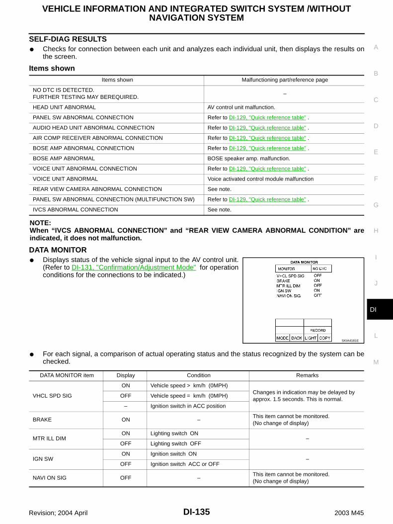
VEHICLE INFORMATION AND INTEGRATED SWITCH SYSTEM /WITHOUT NAVIGATION SYSTEM
DI-135
C
D
E
F
G
H
I
J
L
M
A
B
DI
Revision; 2004 April 2003 M45
SELF-DIAG RESULTS Checks for connection between each unit and analyzes each individual unit, then displays the results on
the screen.
Items shown
NOTE:When “IVCS ABNORMAL CONNECTION” and “REAR VIEW CAMERA ABNORMAL CONDITION” areindicated, it does not malfunction.
DATA MONITOR Displays status of the vehicle signal input to the AV control unit.
(Refer to DI-131, "Confirmation/Adjustment Mode" for operationconditions for the connections to be indicated.)
For each signal, a comparison of actual operating status and the status recognized by the system can bechecked.
Items shown Malfunctioning part/reference page
NO DTC IS DETECTED.FURTHER TESTING MAY BEREQUIRED.
–
HEAD UNIT ABNORMAL AV control unit malfunction.
PANEL SW ABNORMAL CONNECTION Refer to DI-129, "Quick reference table" .
AUDIO HEAD UNIT ABNORMAL CONNECTION Refer to DI-129, "Quick reference table" .
AIR COMP RECEIVER ABNORMAL CONNECTION Refer to DI-129, "Quick reference table" .
BOSE AMP ABNORMAL CONNECTION Refer to DI-129, "Quick reference table" .
BOSE AMP ABNORMAL BOSE speaker amp. malfunction.
VOICE UNIT ABNORMAL CONNECTION Refer to DI-129, "Quick reference table" .
VOICE UNIT ABNORMAL Voice activated control module malfunction
REAR VIEW CAMERA ABNORMAL CONNECTION See note.
PANEL SW ABNORMAL CONNECTION (MULTIFUNCTION SW) Refer to DI-129, "Quick reference table" .
IVCS ABNORMAL CONNECTION See note.
SKIA4181E
DATA MONITOR item Display Condition Remarks
VHCL SPD SIG
ON Vehicle speed > km/h (0MPH)Changes in indication may be delayed by approx. 1.5 seconds. This is normal.
OFF Vehicle speed = km/h (0MPH)
– Ignition switch in ACC position
BRAKE ON –This item cannot be monitored.(No change of display)
MTR ILL DIMON Lighting switch ON
–OFF Lighting switch OFF
IGN SWON Ignition switch ON
–OFF Ignition switch ACC or OFF
NAVI ON SIG OFF –This item cannot be monitored.(No change of display)

DI-136
VEHICLE INFORMATION AND INTEGRATED SWITCH SYSTEM /WITHOUT NAVIGATION SYSTEM
Revision; 2004 April 2003 M45
VERSION Displays version of each unit connected to the AV control unit.
Multifunction Switch Self-Diagnosis Function AKS00404
It can check ON/OFF operation of each switch in the multifunction switch and diagnose the input signals to therear control switch (audio) and steering switch (audio).
STARTING THE SELF-DIAGNOSIS MODE1. Turn ignition switch from OFF to ACC.2. Within 10 seconds press and hold the function switches “1” and
“6 ”simultaneously for 5 seconds.Then the self-diagnosis operates.
EXITING THE SELF-DIAGNOSIS MODE Turn ignition switch OFF, or press and hold the function switches “1” and “6” simultaneously for 5 seconds.
Then the self-diagnosis ends.
DIAGNOSIS FUNCTION It can illuminate all the indicators (LED) in the multifunction switch. It can check for continuity of the switches by sounding the buzzer when the multifunction switch is
pressed. It can check for continuity of harness between multifunction switch and rear control switch (audio), or
steering switch (audio).
SKIA3743E
Version display Remarks
“PANEL SW” Multifunction switch
“HEAD UNIT” AV control unit
“REAR VIEW CAMERA” –
“FRONT SEAT DISPLAY” Display
“AUDIO HEAD UNIT” –
“AIR COMP RECEIVER” Low Tire Pressure Warning Control Unit
“BOSE AMP” –
“IVCS” –
“VOICE UNIT” Voice Activated Control Module
SKIA0609E
VEHICLE INFORMATION AND INTEGRATED SWITCH SYSTEM /WITHOUT NAVIGATION SYSTEM
DI-137
C
D
E
F
G
H
I
J
L
M
A
B
DI
Revision; 2004 April 2003 M45
Power Supply and Ground Circuit Inspection for AV Control Unit AKS004OI
1. CHECK FUSE
Check AV control unit fuses are not blown.
OK or NGOK >> GO TO 2.NG >> If fuse is blown, be sure to eliminate cause of malfunction before installing new fuse. Refer to PG-
2, "POWER SUPPLY ROUTING" .
2. CHECK POWER SUPPLY CIRCUIT
1. Disconnect AV control unit connector. 2. Check voltage between AV control unit and ground.
OK or NGOK >> GO TO 3.NG >> Check harness for open or short between AV control unit and fuse.
3. CHECK GROUND CIRCUIT
1. Turn ignition switch OFF.2. Check continuity between AV control unit harness connector
M78 terminals 1 (B), 4 (B) and ground.
OK or NGOK >> Inspection end.NG >> Repair harness or connector.
Unit Power source Fuse No.
AV control unitBattery power 52
Ignition switch ACC or ON 21
Terminals Ignition switch position
(+)
(-) OFF ACC ONConnector
Terminal (Wire color)
M78
2 (SB) GroundBattery voltage
Battery voltage
Battery voltage
3 (SB) GroundBattery voltage
Battery voltage
Battery voltage
6 (L/B) Ground 0VBattery voltage
Battery voltage
SKIA3607E
Continuity should exist.
SKIA3608E

DI-138
VEHICLE INFORMATION AND INTEGRATED SWITCH SYSTEM /WITHOUT NAVIGATION SYSTEM
Revision; 2004 April 2003 M45
Power Supply and Ground Circuit Inspection for Display AKS004OJ
1. CHECK FUSES
Check 15A fuse [No. 52, located in fuse, fusible link and relay block (J/B)] is blown. Check 10A fuse [No. 21, located in fuse block (J/B) NO. 1] is blown.OK or NGOK >> GO TO 2.NG >> If fuse is blown, be sure to eliminate cause of malfunction before installing new fuse. Refer to PG-
2, "POWER SUPPLY ROUTING" .
2. CHECK POWER SUPPLY CIRCUIT
1. Disconnect display connector. 2. Check voltage between display and ground.
OK or NGOK >> GO TO 3.NG >> Check harness for open or short between display and fuse.
3. CHECK GROUND CIRCUIT
1. Turn ignition switch OFF.2. Check continuity between display and ground.
OK or NGOK >> Inspection end.NG >> Repair harness or connector.
Terminals Ignition switch position
(+)
(–) OFF ACC ONConnector
Terminal(Wire color)
M82
19 (L/B) Ground 0VBattery voltage
Battery voltage
21 (SB) GroundBattery voltage
Battery voltage
Battery voltage
23 (SB) GroundBattery voltage
Battery voltage
Battery voltage
SKIA0552E
Terminals
Continuity(+)
(–)Connector
Terminal(Wire color)
M82 22 (B) GroundYes
M82 24 (B) Ground
SKIA0553E

VEHICLE INFORMATION AND INTEGRATED SWITCH SYSTEM /WITHOUT NAVIGATION SYSTEM
DI-139
C
D
E
F
G
H
I
J
L
M
A
B
DI
Revision; 2004 April 2003 M45
Inspection of Multifunction Switch for Power Supply and Ground Circuit AKS004OK
1. CHECK POWER SUPPLY CIRCUIT
1. Disconnect multifunction switch connector.2. Check voltage between multifunction switch and ground.
OK or NGOK >> GO TO 2.NG >> Check harness for open or short between multifunction switch and fuse.
2. CHECK GROUND CIRCUIT
1. Turn ignition switch OFF.2. Check continuity between multifunction switch harness connec-
tor M83 terminal 2 (B) and ground.
OK or NGOK >> Inspection end.NG >> Repair harness or connector.
Terminals Ignition switch position
(+)
(–) OFF ACC ONConnector
Terminal(wire color)
M83 1 (L/B) Ground 0VBattery voltage
Battery voltage
SKIA0534E
Continuity should exist.
SKIA0535E

DI-140
VEHICLE INFORMATION AND INTEGRATED SWITCH SYSTEM /WITHOUT NAVIGATION SYSTEM
Revision; 2004 April 2003 M45
Vehicle Speed Signal Inspection AKS004OL
1. CHECK HARNESS
1. Disconnect AV control unit and combination meter connector.2. Check continuity between AV control unit harness connector
M77 terminal 33 (OR/L) and ground.
3. Check continuity between AV control unit harness connectorM77 terminal 33 (OR/L) and combination meter harness con-nector M41 terminal 37 (OR/L).
OK or NGOK >> GO TO 2.NG >> Check connector housings for disconnected or loose terminals.
Repair harness or connector.
2. VEHICLE SPEED SIGNAL CHECK 1
1. Connect AV control unit connector.2. Turn ignition switch ON.3. Check voltage between AV control unit harness connector M77
terminal 33 (OR/L) and ground.
OK or NGOK >> GO TO 3.NG >> Replace AV control unit.
3. VEHICLE SPEED SIGNAL CHECK 2
1. Connect combination meter connector.2. Start engine and drive vehicle at more than 40km/h (25MPH).3. Check signal between AV control unit harness connector M77
terminal 33 (OR/L) and ground.
OK or NGOK >> Replace AV control unit.NG >> Check combination meter. Refer to DI-19, "Inspection/
Vehicle Speed Signal" .
Continuity should not exist.
Continuity should exist.SKIA4203E
Approx. 3.5V or more
SKIA3610E
33 (OR/L) - Ground : Refer to DI-119, "Termi-nals and Reference Value for AV Control Unit" .
SKIA4143E

VEHICLE INFORMATION AND INTEGRATED SWITCH SYSTEM /WITHOUT NAVIGATION SYSTEM
DI-141
C
D
E
F
G
H
I
J
L
M
A
B
DI
Revision; 2004 April 2003 M45
Illumination Control Signal Inspection AKS004OM
1. CHECK ILLUMINATION CONTROL SIGNAL
1. Turn ignition switch ON.2. Check voltage between AV control unit and ground.
OK or NGOK >> Replace AV control unit.NG >> Check harness for open or short between AV control unit and BCM.
Ignition Signal Inspection AKS004ON
1. CHECK IGNITION SIGNAL
1. Disconnect AV control unit connector.2. Check voltage between AV control unit and ground.
OK or NGOK >> Replace AV control unit.NG >> Check harness for open or short between AV control unit and fuse.
Terminals
Lighting switch condition
Voltage (V)(+)
(-)Connector
Terminal (Wire color)
M77 25 (R/L) Ground
1st or 2nd position
Approx. 3.5V or more
OFF Less than Approx. 1.5VSKIA3611E
Terminals Ignition switch position
(+)
(-) OFF ACC ONConnector
Terminal (Wire color)
M77 27 (BR/W) Ground 0V 0VBattery voltage
SKIA3612E

DI-142
VEHICLE INFORMATION AND INTEGRATED SWITCH SYSTEM /WITHOUT NAVIGATION SYSTEM
Revision; 2004 April 2003 M45
RGB Screen is not Shown AKS004OO
1. CHECK HARNESS
1. Disconnect AV control unit and display connector.2. Check continuity between AV control unit harness connector
M78 terminal 12 (B) and display harness connector M82 termi-nal 8 (B).
3. Check continuity between AV control unit harness connectorM78 terminal 13 (W) and display harness connector M82 termi-nal 5 (W).
4. Check continuity between AV control unit harness connectorM78 terminal 12 (B), 13 (W) and ground.
OK or NGOK >> GO TO 2.NG >> Check connector housings for disconnected or loose terminals.
Repair harness or connector.
2. CHECK HORIZONTAL SYNCHRONIZATION SIGNAL
1. Connect AV control unit connector and display connector.2. Turn ignition switch ON.3. Check voltage signal between AV control unit harness connector
M78 terminals 13 (W) and 10.
OK or NGOK >> GO TO 3.NG >> Replace display.
3. CHECK RGB AREA SIGNAL
1. Press “INFO” switch.2. Check voltage signal between AV control unit harness connector
M78 terminals 12 (B) and 10.
OK or NGOK >> Replace display. NG >> Replace AV control unit.
Continuity should exist.
Continuity should exist.
Continuity should not exist.
SKIA3594E
13 (W) - 10 : Refer to DI-119, "Termi-nals and Reference Value for AV Control Unit" .
SKIA3595E
12 (B) - 10 : Refer to DI-119, "Termi-nals and Reference Value for AV Control Unit" .
SKIA3596E

VEHICLE INFORMATION AND INTEGRATED SWITCH SYSTEM /WITHOUT NAVIGATION SYSTEM
DI-143
C
D
E
F
G
H
I
J
L
M
A
B
DI
Revision; 2004 April 2003 M45
Color of RGB Image is not Proper AKS004OP
1. CHECK COLOR BAR DIAGNOSIS
Check color tone by “SCREEN ADJUSTMENT” of CONFIRMATION/ADJUSTMENT function.OK or NGOK >> Inspection end.NG >> GO TO 2.

DI-144
VEHICLE INFORMATION AND INTEGRATED SWITCH SYSTEM /WITHOUT NAVIGATION SYSTEM
Revision; 2004 April 2003 M45
2. CHECK HARNESS
1. Turn ignition switch OFF.2. Disconnect AV control unit and display connector.3. Check continuity as follows. When the screen looks bluish
When the screen looks reddish
When the screen looks yellowish
OK or NGOK >> GO TO 3.NG >> Check connector housings for disconnected or loose terminals.
Repair harness or connector.
Terminals
Continuity AV control unit Display
ConnectorTerminal
(Wire color)Connector
Terminal (Wire color)
M7818 (R/L) M82 1 (R/L) Yes
14 M82 4 Yes
Terminals
Continuity(+)(-)
Connector Terminal (Wire color)
M78 14, 18 (R/L) Ground No
Terminals
Continuity AV control unit Display
ConnectorTerminal
(Wire color)Connector
Terminal (Wire color)
M7821 (R/W) M82 2 (R/W) Yes
14 M82 4 Yes
Terminals
Continuity(+)(-)
Connector Terminal (Wire color)
M78 14, 21 (R/W) Ground No
Terminals
Continuity AV control unit Display
ConnectorTerminal
(Wire color)Connector
Terminal (Wire color)
M7824 (B) M82 3 (B) Yes
14 M82 4 Yes
Terminals
Continuity(+)(-)
Connector Terminal (Wire color)
M78 14, 24 (B) Ground No
SKIA3597E
SKIA3598E
SKIA3599E

VEHICLE INFORMATION AND INTEGRATED SWITCH SYSTEM /WITHOUT NAVIGATION SYSTEM
DI-145
C
D
E
F
G
H
I
J
L
M
A
B
DI
Revision; 2004 April 2003 M45
3. CHECK RGB SIGNAL
1. Connect AV control unit and display connector.2. Turn ignition switch ON.3. Display “Color bar” by “CONFIRMATION/ADJUSTMENT” mode.4. Check the following with CONSULT-II or oscilloscope. When the screen looks bluishVoltage signal between AV control unit harness connector M78 ter-minal 18 (R/L) and 14.
When the screen looks reddishVoltage signal between AV control unit harness connector M78 ter-minal 21 (R/W) and 14.
When the screen looks yellowishVoltage signal between AV control unit harness connector M78 terminal 24 (B) and 14.
OK or NGOK >> Replace display.NG >> Replace AV control unit.
RGB Screen Is Rolling AKS004OQ
1. CHECK HARNESS
1. Disconnect AV control unit and display connector.2. Check continuity between AV control unit and ground.
3. Check continuity between AV control unit and display.
OK or NGOK >> GO TO 2.NG >> Check connector housings for disconnected or loose terminals.
Repair harness or connector.
18 (R/L) - 14 : Refer to DI-119, "Termi-nals and Reference Value for AV Control Unit" .
21 (R/W) - 14 : Refer to DI-119, "Termi-nals and Reference Value for AV Control Unit" .
24 (B) - 14 : Refer to DI-119, "Termi-nals and Reference Value for AV Control Unit" .
SKIA3600E
Terminals
Continuity (+)(-)
Connector Terminal (Wire color)
M7815 (G)
Ground No10
Terminals
ContinuityAV control unit Display
ConnectorTerminal
(Wire color)Connector
Terminal (Wire color)
M7815 (G)
M827 (G)
Yes10 4
SKIA3601E
DI-146
VEHICLE INFORMATION AND INTEGRATED SWITCH SYSTEM /WITHOUT NAVIGATION SYSTEM
Revision; 2004 April 2003 M45
2. CHECK RGB SYNCHRONIZING SIGNAL
1. Connect AV control unit and display connector.2. Turn ignition switch ON.3. Check voltage between AV control unit harness connector M78
terminal 15 (G) and 10.
OK or NGOK >> Replace display.NG >> Replace AV control unit.
No A/C Display is Shown AKS004OR
1. CHECK HARNESS
1. Disconnect A/C auto amp. connector and AV control unit connector.2. Check continuity between A/C auto amp. harness connector
M119 terminal 9 (W) and AV control unit harness connector M77terminal 44 (W).
3. Check continuity between A/C auto amp. harness connectorM119 terminal 20 (B) and AV control unit harness connectorM77 terminal 45 (B).
4. Check continuity between AV control unit harness connectorM77 terminals 44 (W), 45 (B) and ground.
Ok or NGOK >> GO TO 2.NG >> Check connector housings for disconnected or loose terminals.
Repair harness or connector.
2. CHECK A/C-AV, AC-CLK COMMUNICATION SIGNAL
1. Connect A/C auto amp. connector.2. Turn ignition switch ON.3. Check voltage between AV control unit harness connector M77
terminals 44 (W), 45 (B) and ground.
OK or NGOK >> GO TO 3.NG >> Replace A/C auto amp.
15 (G) - 10 : Refer to DI-119, "Termi-nals and Reference Value for AV Control Unit" .
SKIA3602E
Continuity should exist.
Continuity should exist.
Continuity should not exist.
SKIA3744E
Approx. 3.5V or more.
SKIA3745E

VEHICLE INFORMATION AND INTEGRATED SWITCH SYSTEM /WITHOUT NAVIGATION SYSTEM
DI-147
C
D
E
F
G
H
I
J
L
M
A
B
DI
Revision; 2004 April 2003 M45
3. CHECK A/C-AV, AC-CLK COMMUNICATION SIGNAL
1. Connect AV control unit connector.2. Turn ignition switch ON.3. Check voltage signal between AV control unit harness connector
M77 terminals 44 (W), 45 (B) and ground.
OK or NGOK >> Replace A/C auto amp.NG >> Replace AV control unit.
A/C Operation Is Not Possible AKS004OS
1. CHECK HARNESS
1. Disconnect A/C auto amp. connector and AV control unit connector.2. Check continuity between A/C auto amp. harness connector
M119 terminal 10 (R) and AV control unit harness connectorM77 terminal 43 (R).
3. Check continuity between A/C auto amp. harness connectorM119 terminal 20 (B) and AV control unit harness connectorM77 terminal 45 (B).
4. Check continuity between AV control unit harness connectorM77 terminals 43 (R), 45 (B) and ground.
OK or NGOK >> GO TO 2.NG >> Check connector housings for disconnected or loose terminals.
Repair harness or connector.
2. CHECK AV-A/C, AC-CLK COMMUNICATION SIGNAL
1. Connect A/C auto amp. connector.2. Turn ignition switch ON.3. Check voltage between AV control unit harness connector M77
terminal 43 (R) and ground.
OK or NGOK >> GO TO 3.NG >> Replace A/C auto amplifier.
44 (W), 45 (B) - Ground :Refer to DI-119, "Termi-nals and Reference Value for AV Control Unit"
SKIA3746E
Continuity should exist.
Continuity should exist.
Continuity should not exist.
SKIA3747E
Approx. 3.5V or more.
SKIA3748E

DI-148
VEHICLE INFORMATION AND INTEGRATED SWITCH SYSTEM /WITHOUT NAVIGATION SYSTEM
Revision; 2004 April 2003 M45
3. CHECK AV-A/C, AC-CLK COMMUNICATION SIGNAL
1. Connect AV control unit connector.2. Turn ignition switch ON.3. Check voltage signal between AV control unit harness connector
M77 terminals 43, 45 and ground with CONSULT-II or oscillo-scope.
OK or NGOK >> Replace A/C auto amp.NG >> Replace AV control unit.
No Fuel Information Is Displayed/No Warning Message Is Displayed AKS0040G
1. CHECK HARNESS
1. Disconnect connectors of AV control unit, combination meter and BCM.2. Check continuity between AV control unit harness connector
M77 terminal 34 (LG) and combination meter harness connectorM42 terminal 56 (LG).
3. Check continuity between AV control unit harness connectorM77 terminal 35 (PU) and combination meter harness connectorM42 terminal 57 (PU).
4. Check continuity between AV control unit harness connectorM77 terminals 34 (LG), 35 (PU) and ground.
OK or NGOK >> GO TO 2.NG >> Check connector housings for disconnected or loose terminals.
Repair harness or connector.
2. CHECK COMMUNICATION SIGNAL (AV-ME)
1. Connect connectors of combination meter, BCM and AV controlunit.
2. Turn ignition switch ON.3. Check voltage signal between AV control unit harness connector
M77 terminal 34 (LG) and ground with CONSULT-II or oscillo-scope.
OK or NGOK >> GO TO 3.NG >> Replace AV control unit.
43 (R), 45 (B) - Ground :Refer to DI-119, "Termi-nals and Reference Value for AV Control Unit"
SKIA3749E
Continuity should exist.
Continuity should exist.
Continuity should not exist.
SKIA4204E
34 (LG) - Ground : Refer to DI-119, "Termi-nals and Reference Value for AV Control Unit" .
SKIA3604E

VEHICLE INFORMATION AND INTEGRATED SWITCH SYSTEM /WITHOUT NAVIGATION SYSTEM
DI-149
C
D
E
F
G
H
I
J
L
M
A
B
DI
Revision; 2004 April 2003 M45
3. CHECK COMMUNICATION SIGNAL (ME-AV)
1. Turn ignition switch ON and display “VEHICLE ELECTRONICSYSTEMS” screen.
2. Check voltage signal between AV control unit harness connectorM77 terminal 35 (PU) and ground with CONSULT-II or oscillo-scope.
OK or NGOK >> Replace AV control unit.NG >> Replace combination meter.
Vehicle Condition Setting Is Not Possible AKS004OT
1. CHECK HARNESS
1. Disconnect connectors of AV control unit, combination meter and BCM.2. Check continuity AV control unit harness connector M77 termi-
nal 34 (LG) and BCM harness connector M4 terminal 31 (LG).
3. Check continuity AV control unit harness connector M77 termi-nal 35 (PU) and BCM harness connector M4 terminal 30 (PU).
4. Check continuity between AV control unit harness connectorM77 terminals 34 (LG), 35 (PU) and ground.
OK or NGOK >> GO TO 2.NG >> Check connector housings for disconnected or loose terminals.
Repair harness or connector.
2. CHECK COMMUNICATION SIGNAL (AV-ME)
1. Connect connectors of AV control unit, combination meter and BCM.2. Turn ignition switch ON.3. Check voltage signal between AV control unit harness connector
M77 terminal 34 (LG) and ground with CONSULT-II or oscillo-scope.
OK or NGOK >> GO TO 3.NG >> Replace AV control unit.
35 (PU) - Ground : Refer to DI-119, "Termi-nals and Reference Value for AV Control Unit" .
SKIA3605E
Continuity should exist.
Continuity should exist.
Continuity should not exist.SKIA3606E
34 (LG) - Ground : Refer to DI-119, "Termi-nals and Reference Value for AV Control Unit" .
SKIA3604E

DI-150
VEHICLE INFORMATION AND INTEGRATED SWITCH SYSTEM /WITHOUT NAVIGATION SYSTEM
Revision; 2004 April 2003 M45
3. CHECK COMMUNICATION SIGNAL (ME-AV)
1. Turn ignition switch ON and display “VEHICLE ELECTRONICSYSTEMS” screen.
2. Check voltage signal between AV control unit harness connectorM77 terminal 35 (PU) and ground with CONSULT-II or oscillo-scope.
OK or NGOK >> Replace AV control unit.NG >> Replace BCM.
Multifunction Switch Does Not Operate AKS004DJ
1. MULTIFUNCTION SWITCH SELF-DIAGNOSIS
Perform multifunction switch self-diagnosis. Refer to DI-136, "Multifunction Switch Self-Diagnosis Function" .Is self-diagnosis result OK?OK >> GO TO 2.NG >> Replace multifunction switch.
2. CHECK POWER AND GROUND CIRCUIT
Check power and ground circuit. Refer to DI-139, "Inspection of Multifunction Switch for Power Supply andGround Circuit" .OK or NGOK >> GO TO 3.NG >> Repair harness or connector.
3. COMMUNICATION CIRCUIT SELF-DIAGNOSIS
Perform the self-diagnosis mode in the self-diagnosis function (If the self-diagnosis cannot be activated withthe multifunction switch, check with CONSULT-II). Refer to DI-127, "Self-Diagnosis Mode" .Is self-diagnosis result OK?OK >> Replace display.NG >> With the self-diagnosis results, check the malfunction part.
Multifunction Switch Indicator Does Not illuminate AKS004DK
1. MULTIFUNCTION SWITCH SELF-DIAGNOSIS
Perform the multifunction switch self-diagnosis. Refer to DI-136, "Multifunction Switch Self-Diagnosis Func-tion" .Is the self-diagnosis result OK?OK >> Replace switch of the malfunctioning indicator.NG >> Replace multifunction switch.
35 (PU) - Ground : Refer to DI-119, "Termi-nals and Reference Value for AV Control Unit" .
SKIA3605E

VEHICLE INFORMATION AND INTEGRATED SWITCH SYSTEM /WITHOUT NAVIGATION SYSTEM
DI-151
C
D
E
F
G
H
I
J
L
M
A
B
DI
Revision; 2004 April 2003 M45
Removal and Installation of Display AKS0040K
REMOVAL1. Remove cluster lid C. Refer to IP-10, "INSTRUMENT PANEL
ASSEMBLY" .2. Remove screws (4), and remove display.
3. Remove screws (4), and remove bracket.
INSTALLATIONInstall in the reverse order of removal.
PKIA1669E
PKIA1670E

DI-152
VEHICLE INFORMATION AND INTEGRATED SWITCH SYSTEM /WITHOUT NAVIGATION SYSTEM
Revision; 2004 April 2003 M45
Disassembly and Assembly of Multifunction Switch AKS0040L
1. Remove screw (8).2. Remove switches.
1. Multifunction switch 2. Escutcheon 3. Hazard switch
4. Defroster, rear defogger switch 5. Function switch 6. Function switch
7. Function switch 8. TAPE and DISC switch 9. A/C switch
10. Escutcheon 11. AM and FM switch 12. Escutcheon
13. Switch assembly 14. Escutcheon 15. Cluster lid C
PKIA1671E

VEHICLE INFORMATION AND INTEGRATED SWITCH SYSTEM /WITHOUT NAVIGATION SYSTEM
DI-153
C
D
E
F
G
H
I
J
L
M
A
B
DI
Revision; 2004 April 2003 M45
Removal and Installation of AV Control Unit AKS0040M
REMOVAL1. Remove cluster lid C. Refer to IP-10, "INSTRUMENT PANEL
ASSEMBLY" .2. Remove warning chime. Refer to DI-71, "Removal and Installa-
tion of Warning Chime" .3. Remove tire pressure warning control unit. Refer to WT-8, "TIRE
PRESSURE WARNING CONTROL UNIT" .4. Remove screws (2), and remove AV control unit with power tool.
5. Remove screws (4), and remove bracket.
INSTALLATIONInstall in the reverse order of removal.
PKIA1673E
PKIA1674E

DI-154
CLOCK
Revision; 2004 April 2003 M45
CLOCK PFP:25820
Wiring Diagram — CLOCK — AKS002K9
TKWM0093E

CLOCK
DI-155
C
D
E
F
G
H
I
J
L
M
A
B
DI
Revision; 2004 April 2003 M45
Removal and Installation AKS002KA
REMOVAL1. Remove cluster lid C, refer to IP-10, "INSTRUMENT PANEL
ASSEMBLY" .2. Remove screws (2), and remove clock.
INSTALLATIONInstall in the reverse order of removal.
PKIA1677E

DI-156
VOICE ACTIVATED CONTROL SYSTEM
Revision; 2004 April 2003 M45
VOICE ACTIVATED CONTROL SYSTEM PFP:28337
System Description AKS004E8
OUTLINE The VACS (Voice-Activated Control System) provides a safe
and convenient way of controlling vehicle systems such as theaudio, auto A/C and navigation (if so equipped). The system iscontrolled by the PTT (Push to talk) button. Voice commandsare picked up by a microphone. When giving a command, voicefeedback will be heard through the speaker, and messages willbe shown on the display. Voice feedback can be turned off. Per-sonal directories of nametags for radio station presets can becreated, and spoken command help is provided.
Refer to Owner’s Manual for voice activated control systemoperating instructions.
Power is supplied at all times. through 15A fuse [No. 52, located in fuse, fusible link and relay block (J/B)]. to Voice Activated Control Module terminal 13.With the ignition switch in the ACC or ON position, power is supplied. through 10A fuse [No. 21, located in the fuse block (J/B) NO. 1]. to Voice Activated Control Module terminal 20.Ground is also supplied to Voice Activated Control Module terminal 14 through grounds B17 and B57.
VOICE ACTIVATED CONTROL FUNCTIONWhen PTT switch pushed ON, signal is sent from steering switch terminal 2 to multifunction switch terminal 7, then via multifunction switch, display and AV and NAVI control unit terminals 47 and 48 (with navigation sys-
tem) or AV control unit terminals 49 and 50 (without navigation system) with AV communication line to voice activated control module terminals 35 and 36.Voice activated control module displays “LISTENING” on screen when PTT switch is ON.When any voice is input into microphone, voice signal is sent from microphone terminals 4 and 5 to voice activated control module terminals 33 and 34.When voice activated control module identifies voice signal as a command, it sends the signal form voice activated control module terminals 35 and 36 to AV and NAVI control unit terminals 47 and 48 (with navigation system) or AV control unit (without navi-
gation system) terminals 49 and 50 with AV communication line.Then AV and NAVI control unit (with navigation system) or AV control unit (without navigation system) sendsoperational signal to display and audio unit and performs the voice command.While voice activated control system is in operation, voice activated control module sends voice signal from voice activated control module terminals 25 and 26 to BOSE speaker amp. terminals 26 and 42, and guides various operations.Also at the same time voice activated control module sends mute signal from voice activated control module terminal 27 to audio unit terminal 9.in order to prevent any noise input into microphone.
SKIA0591E
VOICE ACTIVATED CONTROL SYSTEM
DI-157
C
D
E
F
G
H
I
J
L
M
A
B
DI
Revision; 2004 April 2003 M45
AV COMMUNICATION LINEVoice Activated Control Module is connected to the following units through AV Communication Line. Each unittransmits/receives data with AV communication line. AV and NAVI control unit (with navigation system) AV control unit (without navigation system) Display Audio unit Multifunction switch
DI-158
VOICE ACTIVATED CONTROL SYSTEM
Revision; 2004 April 2003 M45
Schematic AKS004E9
TKWA0620E

VOICE ACTIVATED CONTROL SYSTEM
DI-159
C
D
E
F
G
H
I
J
L
M
A
B
DI
Revision; 2004 April 2003 M45
Wiring Diagram — VOICE — AKS004EA
TKWA0621E

DI-160
VOICE ACTIVATED CONTROL SYSTEM
Revision; 2004 April 2003 M45
TKWA0622E

VOICE ACTIVATED CONTROL SYSTEM
DI-161
C
D
E
F
G
H
I
J
L
M
A
B
DI
Revision; 2004 April 2003 M45
TKWA0623E
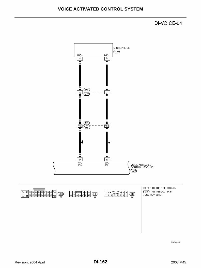
DI-162
VOICE ACTIVATED CONTROL SYSTEM
Revision; 2004 April 2003 M45
TKWA0624E

VOICE ACTIVATED CONTROL SYSTEM
DI-163
C
D
E
F
G
H
I
J
L
M
A
B
DI
Revision; 2004 April 2003 M45
TKWA0625E

DI-164
VOICE ACTIVATED CONTROL SYSTEM
Revision; 2004 April 2003 M45
Terminals and Reference Values for Voice Activated Control Module AKS004OU
Terminals
Item Condition Reference value(+) (–)
Terminal No.
Wire color
Terminal Wire color
13 SB Ground –Power source
(BAT)– Battery voltage
14 B Ground – Ground – Approx. 0V
20 L/OR Ground –Ignition switch
(ACC)ACC Battery voltage
23 – – –Audio shield
ground– –
25 L 23 – Audio output (–)
Voice guide oper-ates.26 R 23 – Audio output (+)
27 Y/R Ground – MutePTT switch (not
operate → operate)Approx. 5V → Approx. 0V
34 R 33 L Mic input Voice mic test
operates.
35 R 37 –Communication
signal (–)–
36 G 37 –Communication
signal (+)–
37 – – – Shield ground – –
PKIA0355E
PKIA0356E
SKIA0176E
SKIA0175E

VOICE ACTIVATED CONTROL SYSTEM
DI-165
C
D
E
F
G
H
I
J
L
M
A
B
DI
Revision; 2004 April 2003 M45
Component Parts and Harness Connector Location AKS004EC
SKIA9344E

DI-166
VOICE ACTIVATED CONTROL SYSTEM
Revision; 2004 April 2003 M45
Trouble Diagnoses AKS004ED
THIS CONDITION IS NOT MALFUNCTION Example of Basic Operational ErrorsThe system should respond correctly to all voice commands. Follow the solutions given in this guide for theappropriate error when any of the following symptom is encountered.Where the solutions are listed by number, try each solution in turn, starting with number one, until the symp-tom is resolved.
Self-Diagnosis Function AKS004EE
DESCRIPTION Diagnosis function consists of the self-diagnosis mode, and the “CONFIRMATION/ADJUSTMENT” mode. Self-diagnosis mode checks for connection between AV and NAVI control unit (with navigation system) or
AV control unit (without navigation system) and voice activated control module and analyzes each unit,then displays the results.
“CONFIRMATION/ADJUSTMENT” function analyzes each microphone.
DIAGNOSIS ITEM
Self-Diagnosis Mode AKS004EF
OPERATION PROCEDURE To start the self-diagnosis mode and to check the diagnosis result, refer to AV-68, "Self-Diagnosis Mode"
(with navigation system), or DI-127, "Self-Diagnosis Mode" (without navigation system).
Symptom Remedy
Displays “COMMAND NOT RECOGNIZED” or the system does not interpret the command correctly.
1. Ensure that the command is valid, see Command list (Refer to Owner’s Manual).
2. Ensure that the command is given after the tone while “ LISTENING” is displayed.
3. Speak clearly without pausing between words and at a level appropriate to the ambient noise level.
4. Ensure that the ambient noise level is not excessive, for example, windows open or defrost on.
NOTE:If it is too noisy to use the microphone, it is likely that voice commands will not be recognized.
5. If optional words of the command have been omitted, then the command should be tried with these in place.
6. If a number of commands have been given in rapid succession resulting in the message “COMMAND NOT RECOGNIZED” to be displayed, then allow the system to recover (approximately one minute) before trying the command again.
7. If the system consistently does not recognize commands, the voice training procedure should be carried out to improve the recognition response for the speaker.
Displays “NO SPEECH DETECTED”.
1. Ensure that the command is given after the tone while “LISTENING” is displayed.
2. Ensure that the command is given within a maximum of five seconds from the end of the tone.
NOTE:Be sure you know what to say before pressing the Voice button.
Displays “NAMETAG NOT UNIQUE”.
1. This response will be received when storing a nametag if the nametag being given has already been stored. This can be confirmed by giving the Radio Directory command.
2. If this response is received and the nametag has not been used already, then it is too similar to an exist-ing nametag or voice grammar and an alternative should be used.
The system consistently selects the wrong nametag.
1. Ensure that the nametag requested matches what was originally stored. This can be confirmed by giving the Radio Directory command.
2. Delete one of the nametags being confused and replace it with a different nametag.
Mode Description
Self-diagnosis
Checks for the connections between AV and NAVI control unit or AV control unit and voice activated control module.
Performs the unit diagnosis of voice activated control module.
CONFIRMATION/ADJUSTMENT
Voice Mic. Test Checks microphone.
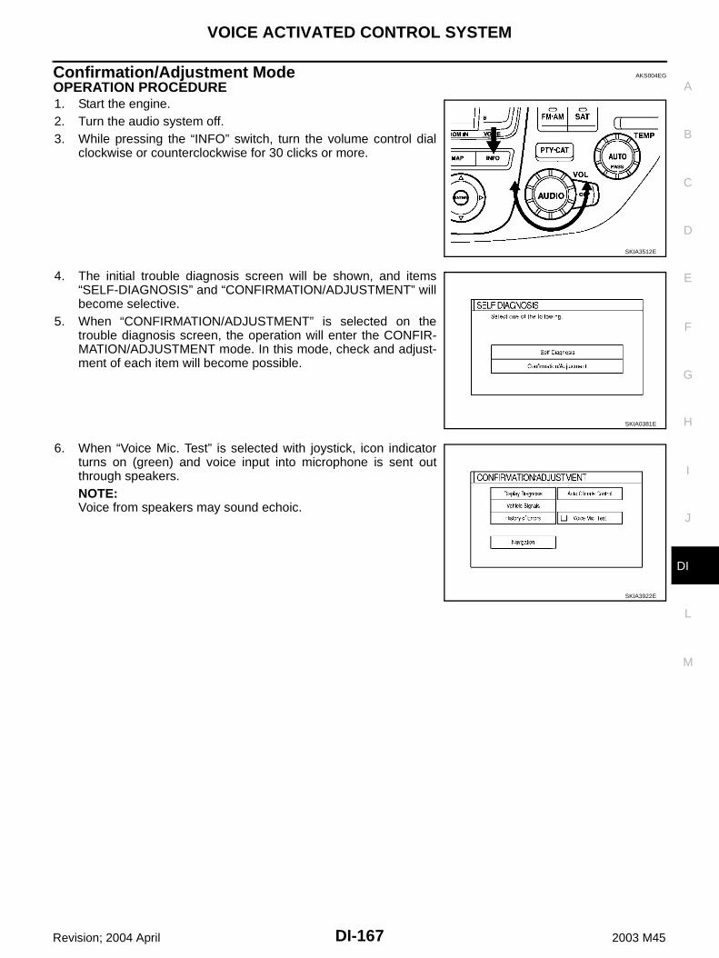
VOICE ACTIVATED CONTROL SYSTEM
DI-167
C
D
E
F
G
H
I
J
L
M
A
B
DI
Revision; 2004 April 2003 M45
Confirmation/Adjustment Mode AKS004EG
OPERATION PROCEDURE1. Start the engine.2. Turn the audio system off.3. While pressing the “INFO” switch, turn the volume control dial
clockwise or counterclockwise for 30 clicks or more.
4. The initial trouble diagnosis screen will be shown, and items“SELF-DIAGNOSIS” and “CONFIRMATION/ADJUSTMENT” willbecome selective.
5. When “CONFIRMATION/ADJUSTMENT” is selected on thetrouble diagnosis screen, the operation will enter the CONFIR-MATION/ADJUSTMENT mode. In this mode, check and adjust-ment of each item will become possible.
6. When “Voice Mic. Test” is selected with joystick, icon indicatorturns on (green) and voice input into microphone is sent outthrough speakers.NOTE:Voice from speakers may sound echoic.
SKIA3512E
SKIA0381E
SKIA3922E

DI-168
VOICE ACTIVATED CONTROL SYSTEM
Revision; 2004 April 2003 M45
Power Supply and Ground Circuit Inspection AKS004OV
1. CHECK FUSES
Check that any of the following fuses for voice activated control module is blown.
OK or NGOK >> GO TO 2.NG >> If fuse is blown, be sure to eliminate cause of malfunction before installing new fuse. Refer to PG-
2, "POWER SUPPLY ROUTING" .
2. CHECK POWER SUPPLY CIRCUIT
Check voltage between voice activated control module harness con-nector B69 terminal 13 (SB), 20 (L/OR) and ground.
OK or NGOK >> GO TO 3.NG >> Check harness between voice activated control module and fuse.
3. CHECK GROUND CIRCUIT
Check continuity between voice activated control module harnessconnector B69 terminal 14 (B) and ground.
OK or NGOK >> Inspection end.NG >> Repair harness or connector.
Unit Power source Fuse No.
Voice Activated Control ModuleBattery 52
Ignition switch ACC or ON 21
Terminals Ignition switch position
(+)
(-) OFF ACC ONConnector
Terminal(Wire color)
B69 13 (SB) GroundBattery voltage
Battery voltage
Battery voltage
B69 20 (L/OR) Ground 0VBattery voltage
Battery voltage SKIA4150E
Continuity should exist.
SKIA4151E
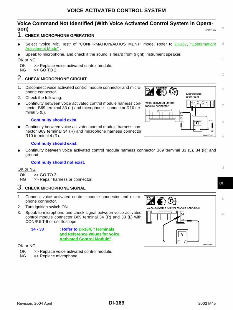
VOICE ACTIVATED CONTROL SYSTEM
DI-169
C
D
E
F
G
H
I
J
L
M
A
B
DI
Revision; 2004 April 2003 M45
Voice Command Not Identified (With Voice Activated Control System in Opera-tion) AKS004OW
1. CHECK MICROPHONE OPERATION
Select “Voice Mic. Test” of “CONFIRMATION/ADJUSTMENT” mode. Refer to DI-167, "Confirmation/Adjustment Mode" .
Speak to microphone, and check if the sound is heard from (right) instrument speaker.OK or NGOK >> Replace voice activated control module.NG >> GO TO 2.
2. CHECK MICROPHONE CIRCUIT
1. Disconnect voice activated control module connector and micro-phone connector.
2. Check the following. Continuity between voice activated control module harness con-
nector B69 terminal 33 (L) and microphone connector R10 ter-minal 5 (L).
Continuity between voice activated control module harness con-nector B69 terminal 34 (R) and microphone harness connectorR10 terminal 4 (R).
Continuity between voice activated control module harness connector B69 terminal 33 (L), 34 (R) andground.
OK or NGOK >> GO TO 3.NG >> Repair harness or connector.
3. CHECK MICROPHONE SIGNAL
1. Connect voice activated control module connector and micro-phone connector.
2. Turn ignition switch ON.3. Speak to microphone and check signal between voice activated
control module connector B69 terminal 34 (R) and 33 (L) withCONSULT-II or oscilloscope.
OK or NGOK >> Replace voice activated control module.NG >> Replace microphone.
Continuity should exist.
Continuity should exist.
Continuity should not exist.
SKIA4152E
34 - 33 : Refer to DI-164, "Terminals and Reference Values for Voice Activated Control Module" .
SKIA4116E

DI-170
VOICE ACTIVATED CONTROL SYSTEM
Revision; 2004 April 2003 M45
No Guide Sound or Beeps AKS004OX
1. CHECK GUIDE SOUND SETTING
Check volume setting of voice activated control system if set as 0 (zero).OK or NGOK >> GO TO 2.NG >> Adjust volume.
2. CHECK BOSE SPEAKER AMP. CIRCUIT
1. Disconnect voice activated control module connector and BOSEspeaker amp. connector.
2. Check the following.– Continuity between voice activated control module harness con-
nector B69 terminal 25 (L) and BOSE speaker amp. harnessconnector B234 terminal 42 (OR/L)
– Continuity between voice activated control module harness con-nector B69 terminal 26 (R) and BOSE speaker amp. harnessconnector B234 terminal 26 (W/L)
– Continuity between voice activated control module harness connector B69 terminal 25 (L), 26 (R) andground
OK or NGOK >> GO TO 3.NG >> Repair harness or connector.
3. CHECK VOICE SIGNAL
1. Connect voice activated control module connector and BOSEspeaker amp.
2. Turn ignition switch ON.3. The Speaker Adaptation (SA) mode ON and voice guide signal
sent out, check signal between voice activated control moduleharness connector B69 terminal 25 (L), 26 (R) and 23.
OK or NGOK >> Replace BOSE speaker amp.NG >> Replace voice activated control module.
Continuity should exist.
Continuity should exist.
Continuity should not exist.
SKIA4153E
25 (L) - 2326 (R) - 23
:Refer to DI-164, "Terminals and Reference Values for Voice Activated Control Module" .
SKIA4154E
VOICE ACTIVATED CONTROL SYSTEM
DI-171
C
D
E
F
G
H
I
J
L
M
A
B
DI
Revision; 2004 April 2003 M45
Voice Activated Control System Not Starting PTT Switch Pushed ON AKS004OY
1. CHECK PTT SWITCH OPERATION
Check PTT switch operation with self-diagnosis of multifunction switch. Refer to DI-136, "Multifunction SwitchSelf-Diagnosis Function" .OK or NGOK >> GO TO 2.NG >> Replace steering switch.
2. CHECK MULTIFUNCTION SWITCH AND VOICE ACTIVATED CONTROL MODULE
Start self-diagnosis mode. Refer to AV-68, "Self-Diagnosis Mode" (with navigation system) or DI-127, "Self-Diagnosis Mode" (without navigation system).Does self-diagnosis mode start?YES >> GO TO 3.NO >> Replace multifunction switch.
3. CHECK VOICE ACTIVATED CONTROL MODULE
Check voice activated control module with self-diagnosis mode started in previous step 2.OK or NGOK >> Replace AV and NAVI control unit (with navigation system), or
Replace AV control unit (without navigation system).NG >> GO TO 4.
4. CHECK POWER SUPPLY AND GROUND CIRCUIT
Check power supply and ground circuit of voice activated control module. Refer to DI-168, "Power Supply andGround Circuit Inspection" .OK or NGOK >> GO TO 5.NG >> Repair harness or connector.

DI-172
VOICE ACTIVATED CONTROL SYSTEM
Revision; 2004 April 2003 M45
5. CHECK AV COMMUNICATION LINE
1. Disconnect voice activated control module and AV and NAVI control unit (with navigation system) or AVcontrol unit (without navigation system) connector.
2. Check the following.– With navigation system
– Without navigation system
OK or NGOK >> Replace voice activated control module.NG >> Repair harness or connector.
Terminals
Continuity(+) (–)
ConnectorTerminal
(Wire color)Connector
Terminal(Wire color)
B71
35 (R) B29 48 (R) Yes
36 (G) B29 47 (G) Yes
37 B29 46 Yes
35 (R) B29 46 No
36 (G) B29 46 No
Terminals
Continuity(+) (–)
ConnectorTerminal
(Wire color)Connector
Terminal(Wire color)
B71
35 (R) M50 50 (R) Yes
36 (G) M50 49 (G) Yes
37 M50 51 Yes
35 (R) M50 51 No
36 (G) M50 51 No
SKIA3924E
SKIA3919E

VOICE ACTIVATED CONTROL SYSTEM
DI-173
C
D
E
F
G
H
I
J
L
M
A
B
DI
Revision; 2004 April 2003 M45
Audio Not Muted with PTT Switch Pushed ON AKS004OZ
1. CHECK AUDIO UNIT CIRCUIT
1. Disconnect voice activated control module connector and Audiounit connector.
2. Check the following.– Continuity between voice activated control module harness con-
nector B69 terminal 27 (Y/R) and Audio unit harness connectorM87 terminal 9 (OR)
– Continuity between voice activated control module harness con-nector B69 terminal 27 (Y/R) and ground
OK or NGOK >> GO TO 2.NG >> Repair harness or connector.
2. CHECK AUDIO UNIT MUTE SIGNAL
1. Connect voice activated control module connector and audiounit connector.
2. Turn ignition switch ON.3. Check voltage between voice activated control module and
ground.
OK or NGOK >> Replace audio unit.NG >> Replace voice activated control module.
Continuity should exist.
Continuity should not exist.SKIA4155E
Terminals
PTT switch condition
Voltage (V)(+)
(–)Connector
Terminal(Wire color)
B69 27 (Y/R) GroundON Approx. 0
OFF Approx. 5
SKIA4156E

DI-174
VOICE ACTIVATED CONTROL SYSTEM
Revision; 2004 April 2003 M45
Audio Mute Not Released AKS004P0
1. AUDIO UNIT MUTE SIGNAL CIRCUIT
1. Disconnect voice activated control module connector and audiounit connector.
2. Check continuity between audio unit harness connector M87 ter-minal 9 (OR) and ground.
OK or NGOK >> GO TO 2.NG >> Repair and replace harness.
2. CHECK MUTE SIGNAL
1. Connect voice activated control module connector and audiounit connector.
2. Turn ignition switch ON.3. Check the following.
OK or NGOK >> Replace audio unit.NG >> Replace voice activated control module.
Continuity should not exist.
SKIA0536E
Unit
TerminalsPTT
switch condition
Voltage (V)(+)
(–)Connector
Terminal (Wire color)
Voice activated control module
B69 27 (Y/R)
Ground
ON Approx. 0
OFF Approx. 5
Audio unit M87 9 (OR)ON Approx. 0
OFF Approx. 5
SKIA4157E

VOICE ACTIVATED CONTROL SYSTEM
DI-175
C
D
E
F
G
H
I
J
L
M
A
B
DI
Revision; 2004 April 2003 M45
Removal and Installation for Voice Activated Control Module AKS004EN
REMOVAL1. Remove trunk side trim. Refer to EI-41, "TRUNK ROOM TRIM & TRUNK LID FINISHER" .2. Remove voice activated control module.
3. Remove bracket from voice activated control module.
INSTALLATIONInstall in the reverse order of removal.
SKIA0500E
SKIA0501E

DI-176
VOICE ACTIVATED CONTROL SYSTEM
Revision; 2004 April 2003 M45