Embed Size (px)
Citation preview

DI-1
DRIVER INFORMATION SYSTEM
K ELECTRICAL
CONTENTS
C
D
E
F
G
H
I
J
L
M
SECTION DIA
B
DI
Revision: 2006 December 2006 FX35/FX45
DRIVER INFORMATION SYSTEM
PRECAUTION ............................................................ 4Precautions for Supplemental Restraint System (SRS) “AIR BAG” and “SEAT BELT PRE-TEN-SIONER” .................................................................. 4
COMBINATION METERS ........................................... 5System Description .................................................. 5
UNIFIED METER CONTROL UNIT ...................... 5UNIFIED METER AND A/C AMP. ......................... 5POWER SUPPLY AND GROUND CIRCUIT ........ 5SPEEDOMETER ................................................... 6TACHOMETER ..................................................... 6WATER TEMPERATURE GAUGE ........................ 6FUEL GAUGE ....................................................... 7ODO/TRIP METER ............................................... 7COMBINATION METER ILLUMINATION CON-TROL ..................................................................... 8FAIL-SAFE ............................................................ 8
Component Parts and Harness Connector Location ..... 9Arrangement of Combination Meter ....................... 10Circuit Diagram .......................................................11Wiring Diagram — METER — ................................ 12Terminals and Reference Value for Combination Meter ...................................................................... 14Terminals and Reference Value for Unified Meter and A/C Amp. ......................................................... 15Self-Diagnosis Mode of Combination Meter ........... 15
SELF-DIAGNOSIS FUNCTION .......................... 15OPERATION PROCEDURE ............................... 15
CONSULT-II Function (METER A/C AMP) ............. 16Trouble Diagnosis .................................................. 16
HOW TO PERFORM TROUBLE DIAGNOSIS ... 16PRELIMINARY CHECK ...................................... 17
Symptom Chart ...................................................... 17Power Supply and Ground Circuit Inspection ........ 18Vehicle Speed Signal Inspection ............................ 19Engine Speed Signal Inspection ............................ 20Engine Coolant Temperature Signal Inspection ..... 21Fuel Level Sensor Signal Inspection ...................... 21Fuel Gauge Pointer Fluctuates, Indicator Wrong Value or Varies ....................................................... 23
Fuel Gauge Does Not Move to FULL Position ....... 23Odo/Trip Meter and Illumination Control Switch Inspection ............................................................... 24Electrical Components Inspection .......................... 24
ODO/TRIP METER AND ILLUMINATION CON-TROL SWITCH .................................................... 24FUEL LEVEL SENSOR UNIT ............................. 24
Removal and Installation of Combination Meter ..... 25Disassembly and Assembly of Combination Meter ... 25
DISASSEMBLY ................................................... 26ASSEMBLY ......................................................... 27
Removal and Installation of Odo/Trip Meter and Illu-mination Control Switch .......................................... 27
REMOVAL ........................................................... 27INSTALLATION ................................................... 27
UNIFIED METER AND A/C AMP .............................. 28System Description ................................................. 28
COMBINATION METER CONTROL FUNCTION ... 28A/C AUTO AMP. FUNCTION ............................... 29OTHER FUNCTIONS .......................................... 29
Schematic ............................................................... 30CONSULT-II Function (METER A/C AMP) ............. 31
CONSULT-II BASIC OPERATION ....................... 31SELF-DIAG RESULTS ........................................ 31DATA MONITOR ................................................. 32
Power Supply and Ground Circuit Inspection ......... 33DTC [U1000] CAN Communication Circuit ............. 34DTC [B2202] Meter Communication Circuit ........... 34DTC [B2205] Vehicle Speed Circuit ........................ 37Removal and Installation of Unified Meter and A/C Amp. ....................................................................... 37
REMOVAL ........................................................... 37INSTALLATION ................................................... 37
WARNING LAMPS .................................................... 38System Description ................................................. 38
OIL PRESSURE WARNING LAMP ..................... 38Schematic ............................................................... 39Wiring Diagram — WARN — .................................. 40Oil Pressure Warning Lamp Stays Off (Ignition Switch ON) ............................................................. 48

DI-2Revision: 2006 December 2006 FX35/FX45
Oil Pressure Warning Lamp Does Not Turn Off (Oil Pressure Is Normal) ................................................ 49Component Inspection ............................................ 51
OIL PRESSURE SWITCH ................................... 51A/T INDICATOR ........................................................ 52
System Description ................................................. 52MANUAL MODE .................................................. 52NOT MANUAL MODE ......................................... 52
Wiring Diagram — AT/IND — ................................. 53A/T Indicator Is Malfunction .................................... 55
WARNING CHIME ..................................................... 56System Description ................................................. 56
POWER SUPPLY AND CIRCUIT ........................ 56IGNITION KEY WARNING CHIME (WITHOUT INTELLIGENT KEY) ............................................ 57IGNITION KEY WARNING CHIME (WITH INTEL-LIGENT KEY) ...................................................... 57LIGHT WARNING CHIME ................................... 58SEAT BELT WARNING CHIME ........................... 58
Component Parts and Harness Connector Location ... 59Schematic ............................................................... 60Wiring Diagram — CHIME — ................................. 61Terminals and Reference Value for BCM ................ 64Terminals and Reference Value for Unified Meter and A/C Amp. ......................................................... 68Terminals and Reference Value for Combination Meter ...................................................................... 69CONSULT-II Function (METER A/C AMP) ............. 69CONSULT-II Function (BCM) .................................. 69
DIAGNOSIS ITEMS DESCRIPTION ................... 69CONSULT-II BASIC OPERATION ....................... 69DATA MONITOR .................................................. 69ACTIVE TEST ..................................................... 70SELF-DIAG RESULTS ........................................ 70
Trouble Diagnosis ................................................... 70HOW TO PERFORM TROUBLE DIAGNOSIS .... 70PRELIMINARY INSPECTION ............................. 71
Symptom Chart ....................................................... 71Power Supply and Ground Circuit Inspection ......... 71Combination Meter Buzzer Circuit Inspection ......... 72Front Door Switch (Driver Side) Signal Inspection ... 74Key Switch Signal Inspection (Without Intelligent Key) ........................................................................ 75Key Switch and Ignition Knob Switch Signal Inspec-tion (With Intelligent Key, When Mechanical Key Is Used) ...................................................................... 76Lighting Switch Signal Inspection ........................... 77Seat Belt Buckle Switch (Driver Side) Signal Inspec-tion .......................................................................... 78Component Inspection ............................................ 79
FRONT DOOR SWITCH (DRIVER SIDE) ........... 79KEY SWITCH ...................................................... 79KEY SWITCH AND IGNITION KNOB SWITCH ... 79SEAT BELT BUCKLE SWITCH (DRIVER SIDE) ... 79
LANE DEPARTURE WARNING SYSTEM ................ 80Precautions for Lane Departure Warning (LDW) system .................................................................... 80System Description ................................................. 80
LDW SYSTEM OPERATION ...............................80POWER SUPPLY AND GROUND CIRCUIT .......82
Action Test ..............................................................83LDW SYSTEM RUNNING TEST .........................83
Camera Aiming Adjustment ....................................83OUTLINE .............................................................83PREPARATION ....................................................83TARGET SETTING ..............................................83VEHICLE HEIGHT CHECK .................................86AIMING ADJUSTMENT .......................................86
Component Parts and Harness Connector Location ...90Schematic ...............................................................91Wiring Diagram — LDW — .....................................92Terminals and Reference Value for LDW Camera Unit ..........................................................................95CONSULT-II Function (LDW) ..................................95
DESCRIPTION ....................................................95CONSULT-II BASIC OPERATION .......................95WORK SUPPORT ...............................................95SELF-DIAG RESULTS .........................................95DATA MONITOR ..................................................96ACTIVE TEST ......................................................97
Trouble Diagnosis ...................................................98HOW TO PERFORM TROUBLE DIAGNOSIS ....98SYMPTOM CHART ..............................................98
Preliminary Inspection .............................................98Power Supply and Ground Circuit Inspection .........99DTC [C1B00] CAMERA UNIT MALF ....................100DTC [C1B01] CAM AIMING INCMP .....................100DTC [C1B02] VHCL SPD DATA MALF .................100DTC [C1B03] ABNRML TEMP DETECT ..............101DTC [U1000] CAN COMM CIRCUIT ....................101DTC [U1010] CONTROL UNIT (CAN) ..................101LDW Chime Circuit Inspection ..............................101LDW Switch Circuit Inspection ..............................102LDW Indicator Lamp Circuit Inspection .................105Turn Signal Input Inspection .................................106Electrical Component Inspection ..........................106
LDW SWITCH ....................................................106Removal and Installation for LDW Camera Unit ...107
REMOVAL ..........................................................107INSTALLATION ..................................................107
Removal and Installation for LDW Chime .............107REMOVAL ..........................................................107INSTALLATION ..................................................107
Removal and Installation for LDW Switch .............107CAN COMMUNICATION .........................................108
System Description ...............................................108CAN Communication Unit .....................................108
COMPASS ...............................................................109Precautions for Compass ......................................109System Description ...............................................109Troubleshooting .................................................... 110Zone Variation Setting Procedure ......................... 111Calibration Procedure ........................................... 111Wiring Diagram — COMPAS — ............................ 112Removal and Installation of Compass ................... 113
CLOCK ....................................................................114

DI-3
C
D
E
F
G
H
I
J
L
M
A
B
DI
Revision: 2006 December 2006 FX35/FX45
Wiring Diagram — CLOCK — ...............................114Removal and Installation of Clock .........................115
REMOVAL ..........................................................115INSTALLATION ..................................................115
REAR VIEW MONITOR ...........................................116System Description ...............................................116
POWER SUPPLY AND GROUND .....................116AV COMMUNICATION LINE ..............................116REAR VIEW CAMERA OPERATION .................116
Component Parts and Harness Connector Location ..117Schematic .............................................................118Wiring Diagram — R/VIEW — ..............................119Terminals and Reference Value for Rear View Cam-era Control Unit .................................................... 122CONSULT-II Function (REARVIEW CAMERA) .... 123
CONSULT-II BASIC OPERATION ..................... 123
WORK SUPPORT ............................................. 123DATA MONITOR ............................................... 123
Side Distance Guideline Correction ...................... 124SIDE DISTANCE GUIDELINE CORRECTION PROCEDURE ................................................... 124
Power Supply and Ground Circuit Inspection ....... 126Rear View Is Not Displayed With The A/T Selector Lever In R-Position ............................................... 127The Rear View Image Is Distorted ........................ 131Removal and Installation of Rear View Camera Con-trol Unit ................................................................. 132
REMOVAL ......................................................... 132INSTALLATION ................................................. 132
Removal and Installation of Rear View Camera ... 133REMOVAL ......................................................... 133INSTALLATION ................................................. 133

DI-4
PRECAUTION
Revision: 2006 December 2006 FX35/FX45
PRECAUTION PFP:00011
Precautions for Supplemental Restraint System (SRS) “AIR BAG” and “SEAT BELT PRE-TENSIONER” NKS002ZB
The Supplemental Restraint System such as “AIR BAG” and “SEAT BELT PRE-TENSIONER”, used alongwith a front seat belt, helps to reduce the risk or severity of injury to the driver and front passenger for certaintypes of collision. This system includes seat belt switch inputs and dual stage front air bag modules. The SRSsystem uses the seat belt switches to determine the front air bag deployment, and may only deploy one frontair bag, depending on the severity of a collision and whether the front occupants are belted or unbelted.Information necessary to service the system safely is included in the SRS and SB section of this Service Man-ual.WARNING: To avoid rendering the SRS inoperative, which could increase the risk of personal injury or death
in the event of a collision which would result in air bag inflation, all maintenance must be per-formed by an authorized NISSAN/INFINITI dealer.
Improper maintenance, including incorrect removal and installation of the SRS, can lead to per-sonal injury caused by unintentional activation of the system. For removal of Spiral Cable and AirBag Module, see the SRS section.
Do not use electrical test equipment on any circuit related to the SRS unless instructed to in thisService Manual. SRS wiring harnesses can be identified by yellow and/or orange harnesses orharness connectors.

COMBINATION METERS
DI-5
C
D
E
F
G
H
I
J
L
M
A
B
DI
Revision: 2006 December 2006 FX35/FX45
COMBINATION METERS PFP:24814
System Description NKS002ZC
UNIFIED METER CONTROL UNIT Speedometer, odo/trip meter, tachometer, fuel gauge and water temperature gauge are controlled by the
unified meter control unit, which is built into the combination meter. Unified meter control unit receives sig-nals from unified meter and A/C amp.
Warning lamp and indicator lamp of combination meter are controlled by signals drawn from the unifiedmeter and A/C amp.
Odo/trip meter, shift position indicator and ICC system display segments can be checked in self-diagnosismode.
Meters/gauges can be checked in self-diagnosis mode.
UNIFIED METER AND A/C AMP.Refer to DI-28, "COMBINATION METER CONTROL FUNCTION" in “UNIFIED METER AND A/C AMP”.
POWER SUPPLY AND GROUND CIRCUITPower is supplied at all times through 10A fuse [No. 19, located in the fuse block (J/B)] to combination meter terminal 8, and to unified meter and A/C amp. terminal 21.With the ignition switch in the ON or START position, power is supplied through 10A fuse [No. 14, located in the fuse block (J/B)] to combination meter terminal 7, through 10A fuse [No. 12, located in the fuse block (J/B)] to unified meter and A/C amp. terminal 22.With the ignition switch in the ACC or ON position, power is supplied through 10A fuse [No. 6, located in the fuse block (J/B)] to combination meter terminal 4, through 15A fuse [No. 10, located in the fuse block (J/B)], and through 15A fuse [No. 11, located in the fuse block (J/B)] to unified meter and A/C amp. terminal 46.Ground is supplied to combination meter terminals 5, 6 and 15 through grounds M35, M45 and M85, to unified meter and A/C amp. terminals 29 and 30 through grounds M35, M45 and M85.

DI-6
COMBINATION METERS
Revision: 2006 December 2006 FX35/FX45
SPEEDOMETERThe speedometer indicates the vehicle speed. ABS actuator and electric unit (control unit) provides a vehicle speed signal to the unified meter and A/C
amp. with CAN communication. Unified meter and A/C amp. converts the vehicle speed signal to the 8-pulse signal, and outputs the vehi-
cle speed signal (8-pulse) to combination meter. Combination meter indicates the vehicle speed according to vehicle speed signal (8-pulse) signal.
TACHOMETERThe tachometer indicates engine speed in revolutions per minute (rpm). ECM provides engine speed signal to unified meter and A/C amp. with CAN communication. Unified meter and A/C amp. transmits engine speed signal to combination meter with communication line. Combination meter indicates the engine speed according to engine speed signal.
WATER TEMPERATURE GAUGEThe water temperature gauge indicates the engine coolant temperature. ECM provides engine coolant temperature signal to unified meter and A/C amp. with CAN communica-
tion. Unified meter and A/C amp. transmits engine coolant temperature signal to combination meter with com-
munication line. Combination meter indicates the engine coolant temperature according to engine coolant temperature
signal.
SKIB7332E
PKIB7631E
PKIB7632E

COMBINATION METERS
DI-7
C
D
E
F
G
H
I
J
L
M
A
B
DI
Revision: 2006 December 2006 FX35/FX45
FUEL GAUGEThe fuel gauge indicates the approximate fuel level in the fuel tank. Unified meter and A/C amp. reads a resistor signal from fuel level sensor.Signal is supplied– from unified meter and A/C amp. terminal 36– through the fuel level sensor unit and fuel pump (main) terminals 5 and 2, and– through the fuel level sensor unit (sub) terminals 2 and 1– to unified meter and A/C amp. terminal 28 for the fuel gauge. Unified meter and A/C amp. provides a fuel level signal to combination meter with communication line. Combination meter indicates the approximate fuel level according to the fuel level signal.
ODO/TRIP METER ABS actuator and electric unit (control unit) provides a vehicle speed signal to the unified meter and A/C
amp. with CAN communication. Unified meter and A/C amp. converts the vehicle speed signal to the 8-pulse signal, and outputs the vehi-
cle speed signal (8-pulse) to combination meter. Combination meter uses the vehicle speed signal (8-pulse) to calculate the mileage, and displays it.
How to Change The Display For Odo/trip MeterSwitch modes with following procedure.
When trip transfer switch is pressed, trip meter display changes. If trip reset switch is pressed for 1 second or more while “trip A”
is displayed, only “trip A” is reset.NOTE:The record of the odo meter is kept even if the battery cable is dis-connected. The record of the trip meter is erased when the batterycable is disconnected.
SKIB8760E
SKIA4817E
DI-8
COMBINATION METERS
Revision: 2006 December 2006 FX35/FX45
COMBINATION METER ILLUMINATION CONTROLDaytime ModeWhen ignition switch is turned ON, combination meter illumination is turned ON by unified meter control unit.
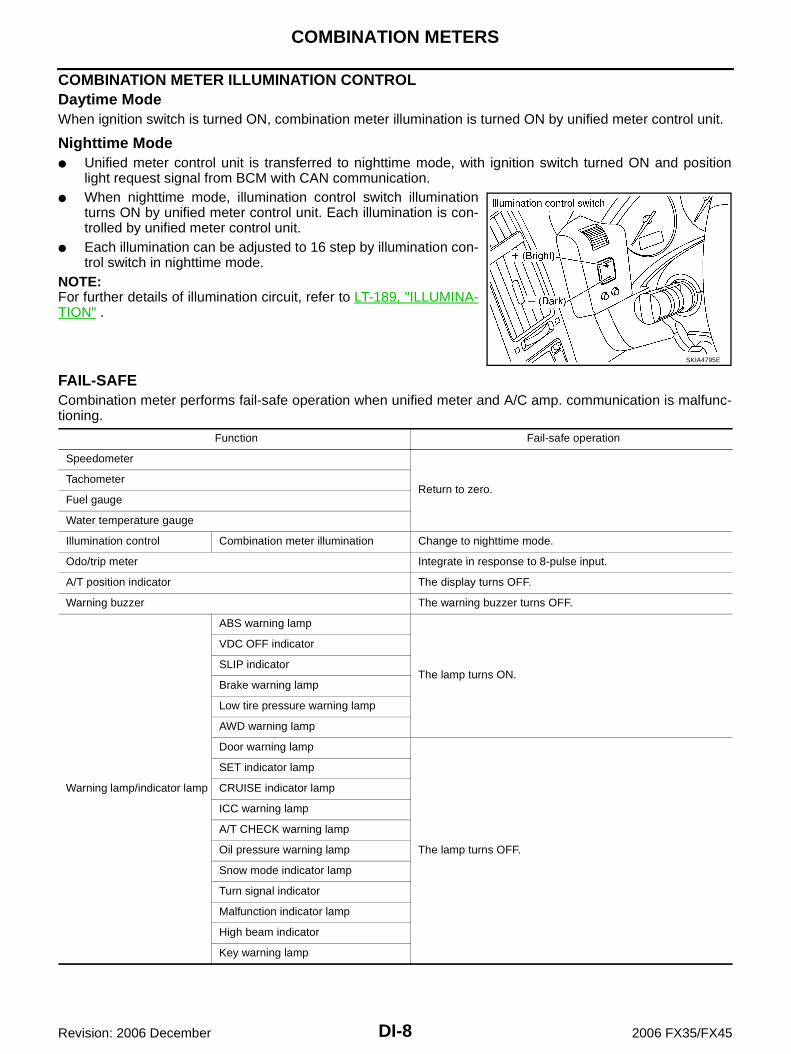
Nighttime Mode Unified meter control unit is transferred to nighttime mode, with ignition switch turned ON and position
light request signal from BCM with CAN communication. When nighttime mode, illumination control switch illumination
turns ON by unified meter control unit. Each illumination is con-trolled by unified meter control unit.
Each illumination can be adjusted to 16 step by illumination con-trol switch in nighttime mode.
NOTE:For further details of illumination circuit, refer to LT-189, "ILLUMINA-TION" .
FAIL-SAFECombination meter performs fail-safe operation when unified meter and A/C amp. communication is malfunc-tioning.
SKIA4795E
Function Fail-safe operation
Speedometer
Return to zero.Tachometer
Fuel gauge
Water temperature gauge
Illumination control Combination meter illumination Change to nighttime mode.
Odo/trip meter Integrate in response to 8-pulse input.
A/T position indicator The display turns OFF.
Warning buzzer The warning buzzer turns OFF.
Warning lamp/indicator lamp
ABS warning lamp
The lamp turns ON.
VDC OFF indicator
SLIP indicator
Brake warning lamp
Low tire pressure warning lamp
AWD warning lamp
Door warning lamp
The lamp turns OFF.
SET indicator lamp
CRUISE indicator lamp
ICC warning lamp
A/T CHECK warning lamp
Oil pressure warning lamp
Snow mode indicator lamp
Turn signal indicator
Malfunction indicator lamp
High beam indicator
Key warning lamp

COMBINATION METERS
DI-9
C
D
E
F
G
H
I
J
L
M
A
B
DI
Revision: 2006 December 2006 FX35/FX45
Component Parts and Harness Connector Location NKS002ZD
SKIB8474E

DI-10
COMBINATION METERS
Revision: 2006 December 2006 FX35/FX45
Arrangement of Combination Meter NKS002ZE
SKIB8475E

COMBINATION METERS
DI-11
C
D
E
F
G
H
I
J
L
M
A
B
DI
Revision: 2006 December 2006 FX35/FX45
Circuit Diagram NKS002ZF
TKWM4341E

DI-12
COMBINATION METERS
Revision: 2006 December 2006 FX35/FX45
Wiring Diagram — METER — NKS002ZG
TKWM4342E

COMBINATION METERS
DI-13
C
D
E
F
G
H
I
J
L
M
A
B
DI
Revision: 2006 December 2006 FX35/FX45
TKWM4343E

DI-14
COMBINATION METERS
Revision: 2006 December 2006 FX35/FX45
Terminals and Reference Value for Combination Meter NKS002ZH
Terminal No.
Wire color
Item
Condition
Reference valueIgnition switch
Operation or condition
1 GVehicle speed signal(8-pulse)
ONSpeedometer operated[When vehicle speed is approx. 40 km/h (25 MPH)]
NOTE:Maximum voltage may be 5 V due to specifications (connected units).
4 LG ACC power supply ACC — Battery voltage
5B Ground ON — Approx. 0 V
6
7 G/Y Ignition power supply ON — Battery voltage
8 R/W Battery power supply OFF — Battery voltage
13 L/BTX communication line (To unified meter and A/C amp.)
ON —
14 PURX communication line (From unified meter and A/C amp.)
ON —
15 B Ground ON — Approx. 0 V
25 — Illumination control switch (–) OFF
Illumination control switch (–) is pressed.
Approx. 0 V
Illumination control switch (–) is released.
Approx. 5 V
26 — Illumination control switch (+) OFF
Illumination control switch (+) is pressed.
Approx. 0 V
Illumination control switch (+) is released.
Approx. 5 V
27 —Odo/trip meter and illumina-tion control switch ground
OFF — Approx. 0 V
35 — Trip reset switch OFFTrip reset switch is pressed Approx. 0 V
Trip reset switch is released Approx. 5 V
36 — Trip transfer switch OFFTrip transfer switch is pressed Approx. 0 V
Trip transfer switch is released Approx. 5 V
PKIA1935E
SKIA3361E
SKIA3362E
COMBINATION METERS
DI-15
C
D
E
F
G
H
I
J
L
M
A
B
DI
Revision: 2006 December 2006 FX35/FX45
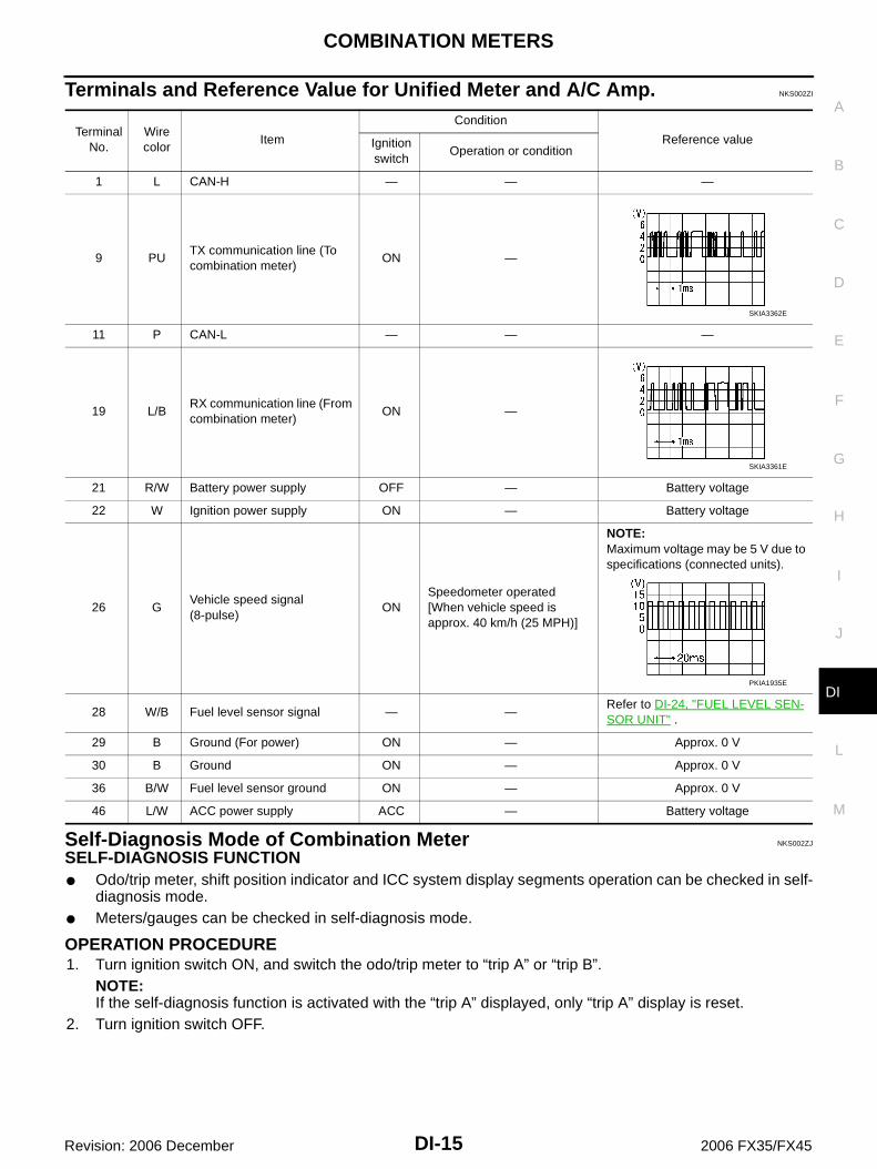
Terminals and Reference Value for Unified Meter and A/C Amp. NKS002ZI
Self-Diagnosis Mode of Combination Meter NKS002ZJ
SELF-DIAGNOSIS FUNCTION Odo/trip meter, shift position indicator and ICC system display segments operation can be checked in self-
diagnosis mode. Meters/gauges can be checked in self-diagnosis mode.
OPERATION PROCEDURE1. Turn ignition switch ON, and switch the odo/trip meter to “trip A” or “trip B”.
NOTE:If the self-diagnosis function is activated with the “trip A” displayed, only “trip A” display is reset.
2. Turn ignition switch OFF.
Terminal No.
Wire color
Item
Condition
Reference valueIgnition switch
Operation or condition
1 L CAN-H — — —
9 PUTX communication line (To combination meter)
ON —
11 P CAN-L — — —
19 L/BRX communication line (From combination meter)
ON —
21 R/W Battery power supply OFF — Battery voltage
22 W Ignition power supply ON — Battery voltage
26 GVehicle speed signal(8-pulse)
ONSpeedometer operated[When vehicle speed is approx. 40 km/h (25 MPH)]
NOTE:Maximum voltage may be 5 V due to specifications (connected units).
28 W/B Fuel level sensor signal — —Refer to DI-24, "FUEL LEVEL SEN-SOR UNIT" .
29 B Ground (For power) ON — Approx. 0 V
30 B Ground ON — Approx. 0 V
36 B/W Fuel level sensor ground ON — Approx. 0 V
46 L/W ACC power supply ACC — Battery voltage
SKIA3362E
SKIA3361E
PKIA1935E

DI-16
COMBINATION METERS
Revision: 2006 December 2006 FX35/FX45
3. Turn ignition switch ON while pressing trip transfer switch andtrip reset switch at the same time.
4. After ignition switch is turned ON, release trip transfer switchand trip reset switch (within 7 seconds after the ignition switch isturned ON).
5. All the segments on the odo/trip meter, shift position indicator and ICC system display illuminates, andsimultaneously the low-fuel warning lamp indicator illuminates. At this time, the unified meter control unitis turned to self-diagnosis mode.
NOTE: Check odo/trip meter switch and combination meter power supply and ground circuit when self-diagno-
sis mode of combination meter does not start. Replace combination meter if the results of the check arenormal.
If any of the segments are not displayed, replace combination meter.6. Each meter/gauge activates during pressing trip reset switch.
(Then low-fuel warning lamp turns OFF.)NOTE: If any of the meters/gauges are not activated, replace the
combination meter. The figure is reference.
CONSULT-II Function (METER A/C AMP) NKS002ZK
Refer to DI-31, "CONSULT-II Function (METER A/C AMP)" in “UNIFIED METER AND A/C AMP”.
Trouble Diagnosis NKS002ZL
HOW TO PERFORM TROUBLE DIAGNOSIS1. Confirm the symptom or customer complaint.2. Perform preliminary check. Refer to DI-17, "PRELIMINARY CHECK" .3. According to the symptom chart, repair or replace the cause of the symptom. Refer to DI-17, "Symptom
Chart" .4. Does the meter operate normally? If so, GO TO 5. If not, GO TO 2.5. INSPECTION END
SKIA4817E
SKIA6170E
SKIA4831E
COMBINATION METERS
DI-17
C
D
E
F
G
H
I
J
L
M
A
B
DI
Revision: 2006 December 2006 FX35/FX45
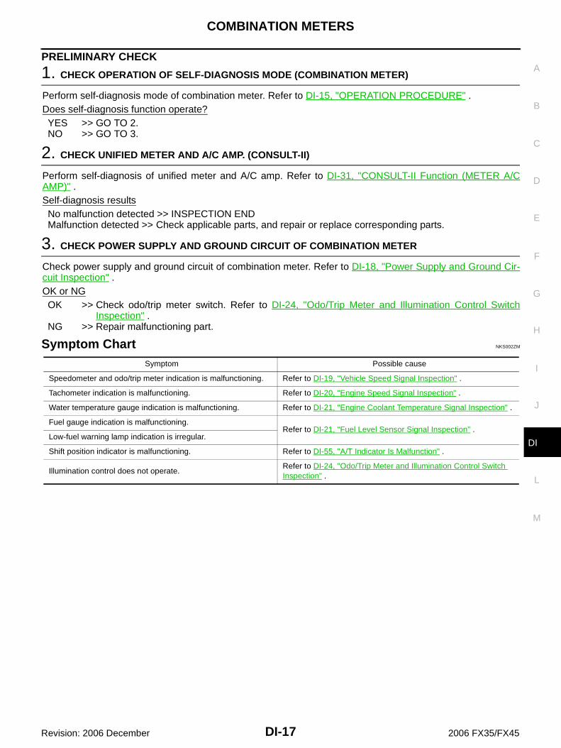
PRELIMINARY CHECK
1. CHECK OPERATION OF SELF-DIAGNOSIS MODE (COMBINATION METER)
Perform self-diagnosis mode of combination meter. Refer to DI-15, "OPERATION PROCEDURE" .Does self-diagnosis function operate?YES >> GO TO 2.NO >> GO TO 3.
2. CHECK UNIFIED METER AND A/C AMP. (CONSULT-II)
Perform self-diagnosis of unified meter and A/C amp. Refer to DI-31, "CONSULT-II Function (METER A/CAMP)" .Self-diagnosis resultsNo malfunction detected >> INSPECTION ENDMalfunction detected >> Check applicable parts, and repair or replace corresponding parts.
3. CHECK POWER SUPPLY AND GROUND CIRCUIT OF COMBINATION METER
Check power supply and ground circuit of combination meter. Refer to DI-18, "Power Supply and Ground Cir-cuit Inspection" .OK or NGOK >> Check odo/trip meter switch. Refer to DI-24, "Odo/Trip Meter and Illumination Control Switch
Inspection" .NG >> Repair malfunctioning part.
Symptom Chart NKS002ZM
Symptom Possible cause
Speedometer and odo/trip meter indication is malfunctioning. Refer to DI-19, "Vehicle Speed Signal Inspection" .
Tachometer indication is malfunctioning. Refer to DI-20, "Engine Speed Signal Inspection" .
Water temperature gauge indication is malfunctioning. Refer to DI-21, "Engine Coolant Temperature Signal Inspection" .
Fuel gauge indication is malfunctioning.Refer to DI-21, "Fuel Level Sensor Signal Inspection" .
Low-fuel warning lamp indication is irregular.
Shift position indicator is malfunctioning. Refer to DI-55, "A/T Indicator Is Malfunction" .
Illumination control does not operate.Refer to DI-24, "Odo/Trip Meter and Illumination Control Switch Inspection" .

DI-18
COMBINATION METERS
Revision: 2006 December 2006 FX35/FX45
Power Supply and Ground Circuit Inspection NKS002ZO
1. CHECK FUSE
Check for blown combination meter fuses.
OK or NGOK >> GO TO 2.NG >> Be sure to eliminate cause of malfunction before installing new fuse. Refer to PG-3, "POWER
SUPPLY ROUTING CIRCUIT" .
2. CHECK POWER SUPPLY CIRCUIT
Check voltage between combination meter harness connector M20terminals 4, 7, 8 and ground.
OK or NGOK >> GO TO 3.NG >> Check harness between combination meter and fuse.
3. CHECK GROUND CIRCUIT
1. Turn ignition switch OFF.2. Disconnect combination meter connector.3. Check continuity between combination meter harness connector
M20 terminals 5, 6, 15 and ground.
OK or NGOK >> INSPECTION ENDNG >> Repair harness or connector.
Power source Fuse No.
Battery power supply 19
ACC power supply 6
Ignition power supply 14
Terminals Ignition switch position
(+)(–) OFF ACC ON
Connector Terminal
M20
4
Ground
0 VBattery voltage
Battery voltage
7 0 V 0 VBattery voltage
8Battery voltage
Battery voltage
Battery voltage
SKIB8525E
5 – Ground: Continuity should exist.6 – Ground
15 – Ground
SKIB8526E

COMBINATION METERS
DI-19
C
D
E
F
G
H
I
J
L
M
A
B
DI
Revision: 2006 December 2006 FX35/FX45
Vehicle Speed Signal Inspection NKS002ZP
Symptom: Speedometer and odo/trip meter indication is malfunction.
1. CHECK COMBINATION METER INPUT SIGNAL
1. Connect CONSULT-II, and start engine.2. Select “METER A/C AMP” on CONSULT-II.3. Using “SPEED METER” on “DATA MONITOR”, compare the
value of “DATA MONITOR” with speedometer pointer of combi-nation meter.
OK or NGOK >> Perform self-diagnosis of ABS actuator and electric unit
(control unit). Refer to BRC-24, "CONSULT-II Functions(VDC)" .
NG >> GO TO 2.
2. CHECK UNIFIED METER AND A/C AMP. OUTPUT SIGNAL
1. Drive vehicle at approximately 40 km/h (25 MPH).2. Check voltage signal between unified meter and A/C amp. har-
ness connector M56 terminal 26 and ground.
OK or NGOK >> GO TO 3.NG-1 >> If monitor indicates “0 V” constantly, perform the following.
1. Check each unit inputting vehicle speed signal (8 pulse), harness and connector between eachunit and unified meter and A/C amp.
2. Repair or replace malfunctioning part.NG-2 >> If monitor indicates “5 V” or “12 V” constantly, replace unified meter and A/C amp. Refer to DI-37,
"Removal and Installation of Unified Meter and A/C Amp." .
SKIB4578E
26 – Ground:
NOTE:Maximum voltage may be 5 V due to specifications (connected units).
SKIB0338E
PKIA1935E

DI-20
COMBINATION METERS
Revision: 2006 December 2006 FX35/FX45
3. CHECK CONTINUITY BETWEEN COMBINATION METER AND UNIFIED METER AND A/C AMP.
1. Turn ignition switch OFF.2. Disconnect combination meter connector and unified meter and A/C amp. connector.3. Check continuity between combination meter harness connector
M20 terminal 1 and unified meter and A/C amp. harness con-nector M56 terminal 26.
OK or NGOK >> Replace combination meter.NG >> Repair harness or connector.
Engine Speed Signal Inspection NKS002ZQ
Symptom: Tachometer indication is malfunction.
1. CHECK COMBINATION METER INPUT SIGNAL
1. Connect CONSULT-II, and start engine.2. Select “METER A/C AMP” on CONSULT-II.3. Using “TACHO METER” on “DATA MONITOR”, compare the
value of “DATA MONITOR” with tachometer pointer of combina-tion meter.
OK or NGOK >> GO TO 2.NG >> Replace combination meter.
2. CHECK UNIFIED METER AND A/C AMP. INPUT SIGNAL
1. Select “ENGINE” on CONSULT-II.2. Using “ENG SPEED” on “DATA MONITOR”, print out the CON-
SULT-II screen when the engine is idling.3. Select “METER A/C AMP” on CONSULT-II.4. Using “TACHO METER” on “DATA MONITOR”, compare the
value of “DATA MONITOR” of the idling speed with that of the“ENG SPEED”.
OK or NGOK >> Perform ECM self-diagnosis. Refer to EC-119, "CON-
SULT-II Function (ENGINE)" (VQ35DE) or EC-780,"CONSULT-II Function (ENGINE)" (VK45DE).
NG >> Replace unified meter and A/C amp. Refer to DI-37,"Removal and Installation of Unified Meter and A/C Amp." .
1 – 26 : Continuity should exist.
SKIB0343E
PKIA2090E
SKIA4367E

COMBINATION METERS
DI-21
C
D
E
F
G
H
I
J
L
M
A
B
DI
Revision: 2006 December 2006 FX35/FX45
Engine Coolant Temperature Signal Inspection NKS002ZR
Symptom: Water temperature gauge indication is malfunction.
1. CHECK COMBINATION METER INPUT SIGNAL
1. Connect CONSULT-II, and start engine.2. Select “METER A/C AMP” on CONSULT-II.3. Using “W TEMP METER” on “DATA MONITOR”, compare the
value of “DATA MONITOR” with water temperature gaugepointer of combination meter.
OK or NGOK >> GO TO 2.NG >> Replace combination meter.
2. CHECK UNIFIED METER AND A/C AMP. INPUT SIGNAL
1. Select “ENGINE” on CONSULT-II.2. Using “COOLAN TEMP/S” on “DATA MONITOR”, print out the
CONSULT-II screen.3. Select “METER A/C AMP” on CONSULT-II.4. Using “W TEMP METER” on “DATA MONITOR”, compare the
value of “DATA MONITOR” with that of the “COOLAN TEMP/S”.OK or NGOK >> Perform ECM self-diagnosis. Refer to EC-119, "CON-
SULT-II Function (ENGINE)" (VQ35DE) or EC-780,"CONSULT-II Function (ENGINE)" (VK45DE).
NG >> Replace unified meter and A/C amp. Refer to DI-37,"Removal and Installation of Unified Meter and A/CAmp." .
Fuel Level Sensor Signal Inspection NKS002ZS
Symptom: Fuel gauge indication is malfunctioning. Low-fuel warning lamp indication is irregular.NOTE:The following symptoms are not malfunctions.Fuel gauge Depending on vehicle posture or driving circumstance, the fuel level in the tank varies, and the pointer
may fluctuate. If the vehicle is fueled with the ignition switch ON, the pointer will move slowly.Low-fuel warning lamp Depending on vehicle posture or driving circumstance, the fuel in the tank flows and the warning lamp ON
timing may change.
Water temperature gauge pointer Reference value of data monitor [°C (°F)]
Hot Approx. 130 (266)
Middle Approx. 70 - 105 (158 - 221)
Cold Approx. 50 (122)
PKIA2091E
SKIA4368E

DI-22
COMBINATION METERS
Revision: 2006 December 2006 FX35/FX45
1. CHECK COMBINATION METER INPUT SIGNAL
1. Select “METER A/C AMP” on CONSULT-II.2. Using “FUEL METER” on “DATA MONITOR”, compare the value
of “DATA MONITOR” with fuel gauge pointer of combinationmeter.
OK or NGOK >> GO TO 2.NG >> Replace combination meter.
2. CHECK FUEL LEVEL SENSOR (SUB) CIRCUIT
1. Turn ignition switch OFF.2. Disconnect unified meter and A/C amp. connector and fuel level sensor unit (sub) connector.3. Check continuity between unified meter and A/C amp. harness
connector (A) M56 terminal 28 and fuel level sensor unit (sub)harness connector (B) B40 terminal 1.
4. Check continuity between unified meter and A/C amp. harnessconnector (A) M56 terminal 28 and ground.
OK or NGOK >> GO TO 3.NG >> Repair harness or connector.
3. CHECK FUEL LEVEL SENSOR (MAIN·SUB) CIRCUIT
1. Disconnect fuel level sensor unit and fuel pump (main) connector.2. Check continuity between fuel level sensor unit (sub) harness
connector (A) B40 terminal 2 and fuel level sensor unit and fuelpump (main) harness connector (B) B39 terminal 2.
3. Check continuity between fuel level sensor unit (sub) harnessconnector (A) B40 terminal 2 and ground.
OK or NGOK >> GO TO 4.NG >> Repair harness or connector.
Fuel gauge pointer Reference value of data monitor [lit.]
Full Approx. 86
Three quarters Approx. 70
Half Approx. 48
A quarter Approx. 25
Empty Approx. 9 PKIA2088E
28 – 1 : Continuity should exist.
28 – Ground : Continuity should not exist.
SKIB8527E
2 – 2 : Continuity should exist.
2 – Ground : Continuity should not exist.
SKIB8697E

COMBINATION METERS
DI-23
C
D
E
F
G
H
I
J
L
M
A
B
DI
Revision: 2006 December 2006 FX35/FX45
4. CHECK FUEL LEVEL SENSOR (MAIN) CIRCUIT
1. Check continuity between fuel level sensor unit and fuel pump(main) harness connector (A) B39 terminal 5 and unified meterand A/C amp. harness connector (B) M56 terminal 36.
2. Check continuity between fuel level sensor unit and fuel pump(main) harness connector (A) B39 terminal 5 and ground.
OK or NGOK >> GO TO 5.NG >> Repair harness or connector.
5. CHECK FUEL LEVEL SENSOR
Check components. Refer to DI-24, "FUEL LEVEL SENSOR UNIT" .OK or NGOK >> Check fuel level sensor unit installation, and check whether the float arm interferes or binds with
any of the internal components in the fuel tank. Repair or replace malfunctioning part, if neces-sary.
NG >> Replace fuel level sensor unit.
Fuel Gauge Pointer Fluctuates, Indicator Wrong Value or Varies NKS002ZU
1. CHECK FUEL GAUGE FLUCTUATION
Test drive vehicle to see if gauge fluctuates only during driving or at the instant of stopping.Does the indication value vary only during driving or at the instant of stopping?YES >> The pointer fluctuation may be caused by fuel level change in the fuel tank. Condition is normal.NO >> Ask the customer about the situation when the symptom occurs in detail, and perform the trouble
diagnosis.
Fuel Gauge Does Not Move to FULL Position NKS002ZV
1. QUESTION 1
Does it take a long time for the pointer to move to FULL position?YES >> GO TO 2.NO >> GO TO 3.
2. QUESTION 2
Was the vehicle fueled with the ignition switch ON?YES >> Be sure to fuel the vehicle with the ignition switch OFF. Otherwise, it will take a long time to move
to FULL position because of the characteristic of the fuel gauge.NO >> GO TO 3.
3. QUESTION 3
Is the vehicle parked on an incline?YES >> Check the fuel level indication with vehicle on a level surface.NO >> GO TO 4.
5 – 36 : Continuity should exist.
5 – Ground : Continuity should not exist.
SKIB8528E

DI-24
COMBINATION METERS
Revision: 2006 December 2006 FX35/FX45
4. QUESTION 4
During driving, does the fuel gauge pointer move gradually toward EMPTY position?YES >> Check the fuel level sensor unit. Refer to DI-24, "FUEL LEVEL SENSOR UNIT" .NO >> The float arm may interfere or bind with any of the components in the fuel tank.
Odo/Trip Meter and Illumination Control Switch Inspection NKS002ZT
Symptom: Illumination control does not operate.
1. CHECK ODO/TRIP METER AND ILLUMINATION CONTROL SWITCH
1. Remove odo/trip meter and illumination control switch. Refer to DI-27, "Removal and Installation of Odo/Trip Meter and Illumination Control Switch" .
2. Check continuity odo/trip meter and illumination control switch. Refer to DI-24, "ODO/TRIP METER ANDILLUMINATION CONTROL SWITCH" .
OK or NGOK >> Replace combination meter.NG >> Replace odo/trip meter and illumination control switch.
Electrical Components Inspection NKS002ZW
ODO/TRIP METER AND ILLUMINATION CONTROL SWITCHCheck continuity between terminals 25, 26, 35 or 36 and 27.
FUEL LEVEL SENSOR UNITFor removal, refer to FL-4, "FUEL LEVEL SENSOR UNIT, FUEL FILTER AND FUEL PUMP ASSEMBLY" .
Fuel Level Sensor Unit and Fuel Pump (Main) Check the resistance between terminals 2 and 5.
*1 and *2: When float rod is in contact with stopper.
If the results of check are NG, check the fuel level sensor unitand fuel pump (main) harness. Refer to DI-25, "Fuel Level Sen-sor Unit and Pump (Main) Harness" .
Terminal Condition Continuity
25
27
Illumination control switch (–) is pressed. Yes
Illumination control switch (–) is released. No
26Illumination control switch (+) is pressed. Yes
Illumination control switch (+) is released. No
35Trip transfer switch is pressed. Yes
Trip transfer switch is released. No
36Trip reset switch is pressed. Yes
Trip reset switch is released. No
SKIB8529E
Terminal Float position [mm (in)]Resistance value [Ω]
2 5*1 Full 236 (9.29) Approx. 3
*2 Empty 29 (1.14) Approx. 80
SKIB3550J

COMBINATION METERS
DI-25
C
D
E
F
G
H
I
J
L
M
A
B
DI
Revision: 2006 December 2006 FX35/FX45
Fuel Level Sensor Unit and Pump (Main) HarnessCheck continuity at following terminals.
If the results of check are NG, replace fuel pump assembly. If theresults of check are OK, replace fuel level sensor unit.
Fuel Level Sensor Unit (Sub)Check resistance between terminals 1 and 2.
*1 and *2: When float rod is in contact with stopper.
Removal and Installation of Combination Meter NKS003IC
Refer to IP-10, "INSTRUMENT PANEL ASSEMBLY" .
Disassembly and Assembly of Combination Meter NKS002ZY
Terminal Continuity
2 - Signal terminal (A)Yes
5 - Ground terminal (B)
SKIB3551J
Terminal Float position [mm (in)]Resistance value [Ω]
1 2*1 Full 6 (0.24) Approx. 3
*2 Empty 203 (7.99) Approx. 48
SKIB8530E
1. Rear cover 2. Screws 3. Plate
4. Unified meter control unit assembly 5. Front cover 6. Reinforcing metal
7. Switch and meter housing
SKIA5790E

DI-26
COMBINATION METERS
Revision: 2006 December 2006 FX35/FX45
DISASSEMBLY1. Remove screws (A) and remove rear cover (1).2. Disconnect odo/trip meter and illumination control switch con-
nector (2).
3. Remove screws (A).
4. Remove tabs (A) and remove switch and meter housing (1).
5. Remove screws (A) and remove reinforcing metal (1).
SKIB8477E
SKIB8478E
SKIB8479E
SKIB8480E

COMBINATION METERS
DI-27
C
D
E
F
G
H
I
J
L
M
A
B
DI
Revision: 2006 December 2006 FX35/FX45
6. Remove screws (A) and remove plate (1).
7. Disengage tabs (A) to separate front cover (1).
ASSEMBLYAssembly is the reverse order of disassembly.
Removal and Installation of Odo/Trip Meter and Illumination Control Switch NKS002ZZ
REMOVAL1. Remove combination meter. Refer to IP-10, "INSTRUMENT PANEL ASSEMBLY" .2. Remove switch and meter housing. Refer to DI-25, "Disassembly and Assembly of Combination Meter" .3. Remove screws (2), and remove switch assembly.
4. Remove screws (5), and remove odo/trip meter and illuminationcontrol switch.
INSTALLATIONInstallation is the reverse order of removal.
SKIB8481E
SKIB8482E
SKIA5795E
SKIA5796E

DI-28
UNIFIED METER AND A/C AMP
Revision: 2006 December 2006 FX35/FX45
UNIFIED METER AND A/C AMP PFP:27760
System Description NKS00300
For the unified meter and A/C amp., the signal required for controlling the combination meter are inte-grated in the A/C auto amp.
The unified meter and A/C amp. corresponds to a CONSULT-II function (self-diagnosis results, CAN diag-nosis support monitor, data monitor).
COMBINATION METER CONTROL FUNCTION Unified meter and A/C amp. receives necessary information for combination meter from each unit by CAN
communication. Unified meter and A/C amp. transmits a signals with communication line (TX, RX) between unified meter
and A/C amp. and combination meter.
Input/output signals between unified meter and A/C amp. and combination meter.
NOTE:Combination meter performs fail-safe operation when unified meter and A/C amp. communication is malfunctioning. Refer to DI-8,"FAIL-SAFE" .
Unit Input Output
Unified meter and A/C amp.
Seat belt buckle switch signal (Driver's side)
Parking brake signal
Illumination control nighttime required signal
Refuel status signal
Low-fuel warning lamp condition signal
Combination meter receive error signal
Delivery destination data signal
Combination meter specifications signal
Vehicle speed signal (8-pulse)
Engine speed signal
Engine coolant temperature signal
Fuel level sensor signal (resistance value)
Malfunction indicator lamp signal
ABS warning lamp signal
Low tire pressure warning lamp signal
Brake warning lamp signal
A/T CHECK warning lamp signal
ICC warning lamp signal
Oil pressure switch signal
Door switch signal
AWD warning lamp signal
Key warning lamp signal
VDC OFF indicator lamp signal
SLIP indicator lamp signal
CRUISE indicator lamp signal
SET indicator lamp signal
High beam request signal
Turn indicator signal
Snow mode switch signal
ICC system display signal
Shift position indicator signal
Manual mode indicator signal
Manual mode gear position signal
CAN communication condition signal of A/T
Position lights request signal
Buzzer output signal
UNIFIED METER AND A/C AMP
DI-29
C
D
E
F
G
H
I
J
L
M
A
B
DI
Revision: 2006 December 2006 FX35/FX45
A/C AUTO AMP. FUNCTIONUnified meter and A/C amp. controls each operation for A/C auto amp. Regarding A/C control, refer to ATC-30, "AIR CONDITIONER CONTROL" in ATC section.
OTHER FUNCTIONSDrive Computer FunctionThe signals required for the distance to empty (DTE) display are centralized in the unified meter and A/Camp., converted into data, and transmitted to the display unit (without NAVI) and display control unit (withNAVI) using CAN communication.
Signal Buffer FunctionUnified meter and A/C amp. transmits each signal to other units with CAN communication.

DI-30
UNIFIED METER AND A/C AMP
Revision: 2006 December 2006 FX35/FX45
Schematic NKS00303
TKWM4365E

UNIFIED METER AND A/C AMP
DI-31
C
D
E
F
G
H
I
J
L
M
A
B
DI
Revision: 2006 December 2006 FX35/FX45
CONSULT-II Function (METER A/C AMP) NKS00304
CONSULT-II can display each diagnostic item using the diagnostic test modes shown following.
CONSULT-II BASIC OPERATIONRefer to GI-38, "CONSULT-II Start Procedure" .
SELF-DIAG RESULTSOperation Procedure1. Touch “SELF-DIAG RESULTS” on “SELECT DIAG MODE” screen.2. Self-diagnosis results are displayed.
Display Item List
NOTE:“TIME” means the following. 0: Means detected malfunction at present. (From malfunction detection to turning ignition switch OFF) 1 - 63: Means detected malfunction in the past. (Displays the number of ignition switch OFF → ON after
detecting malfunction. “SELF-DIAG RESULTS” is erased when exceeding “63”.)
System Diagnosis mode DescriptionReference
page
METER A/C AMP
SELF-DIAG RESULTSUnified meter and A/C amp. checks the conditions and dis-plays memorized error.
DI-31
CAN DIAG SUPPORT MNTRThe results of transmit/receive diagnosis of CAN communi-cation can be read.
LAN-16
DATA MONITORDisplays unified meter and A/C amp. input data in real time.
DI-32
SKIA4956E
Display item [Code] Malfunction is detected when...Reference
page
CAN COMM CIRC [U1000]
Malfunction is detected in CAN communication.
CAUTION:Even when there is no malfunction on CAN communication system, malfunction may be misinterpreted when battery has low voltage (when maintaining 7 - 8 V for about 2 seconds) or 10A fuse [No. 19, located in the fuse block (J/B)] is dis-connected.
DI-34
METER COMM CIRC [B2202]Malfunction is detected in communication of between combination meter and unified meter and A/C amp.
DI-34
VEHICLE SPEED CIRC [B2205]
When an erroneous speed signal is input for 1 second.
CAUTION:Even when there is no malfunction on speed signal system, malfunction may be misinterpreted when battery has low voltage (when maintaining 7 - 8 V for about 2 seconds).
DI-37

DI-32
UNIFIED METER AND A/C AMP
Revision: 2006 December 2006 FX35/FX45
DATA MONITOROperation Procedure1. Touch “DATA MONITOR” on “SELECT DIAG MODE” screen.2. Touch either “MAIN SIGNALS” or “SELECTION FROM MENU” on the “DATA MONITOR” screen.
3. When “SELECTION FROM MENU” is selected, touch individual items to be monitored. When “MAIN SIG-NALS” is selected, main items will be monitored.
4. Touch “START”.5. Touch “RECORD” while monitoring, then the status of the moni-
tored item can be recorded. To stop recording, touch “STOP”.
Display Item ListX: Applicable
MAIN SIGNALS Monitors main signals.
SELECTION FROM MENU Selects and monitors individual signal.
SKIA4957E
Display item [Unit]MAIN
SIGNALSSELECTION FROM MENU
Contents
SPEED METER [km/h] or [mph] X XDisplays the value of vehicle speed signal, which is input from ABS actuator and electric unit (control unit).
SPEED OUTPUT [km/h] or [mph] X XDisplays the value of vehicle speed signal, which is transmitted to each unit with CAN communication.
TACHO METER [rpm] X XDisplays the value of engine speed signal, which is input from ECM.
W TEMP METER [°C] or [°F] X XDisplays the value of engine coolant temperature signal, which is input from ECM.
FUEL METER [lit.] X XDisplays the value, which processes a resistance signal from fuel gauge.
DISTANCE [km] or [mile] X XDisplays the value, which is calculated by vehicle speed signal from ABS actuator and electric unit (control unit), fuel gauge and fuel consumption from ECM.
FUEL W/L [ON/OFF] X X Indicates [ON/OFF] condition of low-fuel warning lamp.
MIL [ON/OFF] X Indicates [ON/OFF] condition of malfunction indicator lamp.
AIR PRES W/L [ON/OFF] X Indicates [ON/OFF] condition of low tire pressure warning lamp.
SEAT BELT W/L [ON/OFF] X Indicates [ON/OFF] condition of seat belt warning lamp.
BUZZER [ON/OFF] X X Indicates [ON/OFF] condition of buzzer.
DOOR W/L [ON/OFF] X Indicates [ON/OFF] condition of door warning lamp.
HI-BEAM IND [ON/OFF] X Indicates [ON/OFF] condition of high beam indicator.
TURN IND [ON/OFF] X Indicates [ON/OFF] condition of turn indicator.
OIL W/L [ON/OFF] X Indicates [ON/OFF] condition of oil pressure warning lamp.
VDC/TCS IND [ON/OFF] X Indicates [ON/OFF] condition of VDC OFF indicator lamp.
ABS W/L [ON/OFF] X Indicates [ON/OFF] condition of ABS warning lamp.
SLIP IND [ON/OFF] X Indicates [ON/OFF] condition of SLIP indicator lamp.
BRAKE W/L [ON/OFF]* X Indicates [ON/OFF] condition of brake warning lamp.
KEY G W/L [ON/OFF] X Indicates [ON/OFF] condition of key warning lamp (green).
KEY R W/L [ON/OFF] X Indicates [ON/OFF] condition of key warning lamp (red).

UNIFIED METER AND A/C AMP
DI-33
C
D
E
F
G
H
I
J
L
M
A
B
DI
Revision: 2006 December 2006 FX35/FX45
NOTE:Monitored item that does not match the vehicle is deleted from the display automatically.*: Monitor keeps indicating “OFF” when brake warning lamp is on by the parking brake operation or low brake fluid level.
Power Supply and Ground Circuit Inspection NKS003HN
1. CHECK FUSE
Check for blown unified meter and A/C amp. fuses.
OK or NGOK >> GO TO 2.NG >> Be sure to eliminate cause of malfunction before installing new fuse. Refer to PG-3, "POWER
SUPPLY ROUTING CIRCUIT" .
KEY KNOB W/L [ON/OFF] X Indicates [ON/OFF] condition of key knob warning lamp.
M RANGE SW [ON/OFF] X X Indicates [ON/OFF] condition of manual mode range switch.
NM RANGE SW [ON/OFF] X XIndicates [ON/OFF] condition of except for manual mode range switch.
AT SFT UP SW [ON/OFF] X X Indicates [ON/OFF] condition of A/T shift-up switch.
AT SFT DWN SW [ON/OFF] X X Indicates [ON/OFF] condition of A/T shift-down switch.
BRAKE SW [ON/OFF] X Indicates [ON/OFF] condition of brake switch (stop lamp switch).
AT-M IND [ON/OFF] X X Indicates [ON/OFF] condition of A/T manual mode indicator.
AT-M GEAR [5-1] X X Indicates [5-1] condition of A/T manual mode gear position.
P RANGE IND [ON/OFF] X X Indicates [ON/OFF] condition of A/T shift P range indicator.
R RANGE IND [ON/OFF] X X Indicates [ON/OFF] condition of A/T shift R range indicator.
N RANGE IND [ON/OFF] X X Indicates [ON/OFF] condition of A/T shift N range indicator.
D RANGE IND [ON/OFF] X X Indicates [ON/OFF] condition of A/T shift D range indicator.
AT CHECK W/L X Indicates [ON/OFF] condition of AT CHECK warning lamp.
CRUISE IND [ON/OFF] X Indicates [ON/OFF] condition of CRUISE indicator lamp.
SET IND [ON/OFF] X Indicates [ON/OFF] condition of SET indicator lamp.
CRUISE W/L [ON/OFF] X Indicates [ON/OFF] condition of ICC warning lamp.
4WD LOCK SW [ON/OFF] X This item is not used for this model. “OFF” is always displayed.
4WD LOCK IND [ON/OFF] X This item is not used for this model. “OFF” is always displayed.
4WD W/L [ON/OFF] X Indicates [ON/OFF] condition of AWD warning lamp.
Display item [Unit]MAIN
SIGNALSSELECTION FROM MENU
Contents
Power source Fuse No.
Battery power supply 19
ACC power supply 10, 11
Ignition power supply 12

DI-34
UNIFIED METER AND A/C AMP
Revision: 2006 December 2006 FX35/FX45
2. CHECK POWER SUPPLY CIRCUIT
Check voltage between unified meter and A/C amp. harness con-nector terminals and ground.
OK or NGOK >> GO TO 3.NG >> Check harness between unified meter and A/C amp. and fuse.
3. CHECK GROUND CIRCUIT
1. Turn ignition switch OFF.2. Disconnect unified meter and A/C amp. connector.3. Check continuity between unified meter and A/C amp. harness
connector M56 terminals 29, 30 and ground.
OK or NGOK >> INSPECTION ENDNG >> Repair harness or connector.
DTC [U1000] CAN Communication Circuit NKS00305
Symptom: Display “CAN COMM CIRC [U1000]” at the result of self-diagnosis for unified meter and A/C amp.
1. CHECK CAN COMMUNICATION
1. Select “SELF-DIAG RESULTS” mode for “METER A/C AMP” with CONSULT-II.2. Print out CONSULT-II screen.
>> Go to “LAN system”. Refer to LAN-3, "Precautions When Using CONSULT-II" .
DTC [B2202] Meter Communication Circuit NKS00306
Symptom: Display “METER COMM CIRC [B2202]” at the result of self-diagnosis for unified meter and A/Camp.
1. CHECK CONNECTOR
Check combination meter, unified meter and A/C amp. and terminals (combination meter side, unified meterand A/C amp. side, and harness side) for looseness or bent terminals.OK or NGOK >> GO TO 2.NG >> Repair terminal or connector.
Terminals Ignition switch position
(+)(–) OFF ACC ON
Connector Terminal
M56
21
Ground
Battery voltage
Battery voltage
Battery voltage
22 0 V 0 VBattery voltage
M57 46 0 VBattery voltage
Battery voltage
PKIB3570E
29 – Ground: Continuity should exist.
30 – Ground
SKIA5202E

UNIFIED METER AND A/C AMP
DI-35
C
D
E
F
G
H
I
J
L
M
A
B
DI
Revision: 2006 December 2006 FX35/FX45
2. CHECK METER/GAUGES VISUALLY
Check the pointer on the meter/gauge fluctuate at the engine start.Is the fluctuation acceptable?YES >> GO TO 3.NO >> GO TO 6.
3. CHECK CONTINUITY COMMUNICATION CIRCUIT (TX: COMBINATION METER)
1. Turn ignition switch OFF.2. Disconnect combination meter connector and unified meter and A/C amp. connector.3. Check continuity between combination meter harness connector
M20 terminal 13 and unified meter and A/C amp. harness con-nector M55 terminal 19.
4. Check continuity between combination meter harness connectorM20 terminal 13 and ground.
OK or NGOK >> GO TO 4.NG >> Repair harness or connector.
4. CHECK VOLTAGE OF UNIFIED METER AND A/C AMP.
1. Connect unified meter and A/C amp. connector.2. Turn ignition switch ON.3. Check voltage between combination meter harness connector
M20 terminal 13 and ground.
OK or NGOK >> GO TO 5.NG >> Replace unified meter and A/C amp. Refer to DI-37,
"Removal and Installation of Unified Meter and A/CAmp."
13 – 19 : Continuity should exist.
13 – Ground : Continuity should not exist.
SKIA4837E
13 – Ground : Approx. 5 V
SKIA4886E

DI-36
UNIFIED METER AND A/C AMP
Revision: 2006 December 2006 FX35/FX45
5. CHECK VOLTAGE SIGNAL OF COMBINATION METER
1. Turn ignition switch OFF.2. Connect combination meter connector.3. Turn ignition switch ON.4. Check voltage signal between combination meter harness con-
nector M20 terminal 13 and ground.
OK or NGOK >> Replace unified meter and A/C amp. Refer to DI-37,
"Removal and Installation of Unified Meter and A/C Amp." .NG >> Replace combination meter.
6. CHECK CONTINUITY COMMUNICATION CIRCUIT (RX: COMBINATION METER)
1. Turn ignition switch OFF.2. Disconnect combination meter connector and unified meter and A/C amp. connector.3. Check continuity between combination meter harness connector
M20 terminal 14 and unified meter and A/C amp. harness con-nector M55 terminal 9.
4. Check continuity between combination meter harness connectorM20 terminal 14 and ground.
OK or NGOK >> GO TO 7.NG >> Repair harness or connector.
7. CHECK VOLTAGE OF COMBINATION METER
1. Connect combination meter connector.2. Turn ignition switch ON.3. Check voltage between unified meter and A/C amp. harness
connector M55 terminal 9 and ground.
OK or NGOK >> GO TO 8.NG >> Replace combination meter.
13 – Ground:
SKIA9258E
SKIA3361E
14 – 9 : Continuity should exist.
14 – Ground : Continuity should not exist.
SKIA4836E
9 – Ground : Approx. 5 V
PKIB3587E

UNIFIED METER AND A/C AMP
DI-37
C
D
E
F
G
H
I
J
L
M
A
B
DI
Revision: 2006 December 2006 FX35/FX45
8. CHECK VOLTAGE SIGNAL OF UNIFIED METER AND A/C AMP.
1. Turn ignition switch OFF.2. Connect unified meter and A/C amp. connector.3. Turn ignition switch ON.4. Check voltage signal between combination meter harness con-
nector M20 terminal 14 and ground.
OK or NGOK >> Replace combination meter.NG >> Replace unified meter and A/C amp. Refer to DI-37, "Removal and Installation of Unified Meter
and A/C Amp." .
DTC [B2205] Vehicle Speed Circuit NKS00307
Symptom: Display “VEHICLE SPEED CIRC [B2205]” at the result of self-diagnosis for unified meter and A/Camp.Perform self-diagnosis of ABS actuator and electric unit (control unit), and repair or replace malfunctioningparts. Refer to BRC-24, "CONSULT-II Functions (VDC)" .
Removal and Installation of Unified Meter and A/C Amp. NKS00308
REMOVAL1. Remove the audio unit (1). Refer to AV-43, "Removal and Instal-
lation of Audio Unit" .2. Remove the screws (A).3. Remove the screws (B) and remove the unified meter and A/C
amp. (2).
INSTALLATIONInstallation is the reverse order of removal.NOTE:Use appropriate screws for each, as screws for audio unit and display unit are different from that for unifiedmeter and A/C amp.
14 – Ground:
SKIA9260E
SKIA3362E
SKIB8483E

DI-38
WARNING LAMPS
Revision: 2006 December 2006 FX35/FX45
WARNING LAMPS PFP:24814
System Description NKS003HX
OIL PRESSURE WARNING LAMPOil pressure warning lamp turns ON when reducing engine oil pressure abnormally. IPDM E/R reads oil pressure switch signal from oil pressure switch, and transmits the signal to unified
meter and A/C amp. through BCM with CAN communication. Unified meter and A/C amp. transmits oil pressure switch signal to combination meter with communication
line. Combination meter turns oil pressure warning lamp ON with received oil pressure switch signal.
PKIB7655E

WARNING LAMPS
DI-39
C
D
E
F
G
H
I
J
L
M
A
B
DI
Revision: 2006 December 2006 FX35/FX45
Schematic NKS0030C
TKWM4345E

DI-40
WARNING LAMPS
Revision: 2006 December 2006 FX35/FX45
Wiring Diagram — WARN — NKS0030D
TKWM4346E

WARNING LAMPS
DI-41
C
D
E
F
G
H
I
J
L
M
A
B
DI
Revision: 2006 December 2006 FX35/FX45
TKWM4347E

DI-42
WARNING LAMPS
Revision: 2006 December 2006 FX35/FX45
TKWM4348E

WARNING LAMPS
DI-43
C
D
E
F
G
H
I
J
L
M
A
B
DI
Revision: 2006 December 2006 FX35/FX45
TKWM4349E

DI-44
WARNING LAMPS
Revision: 2006 December 2006 FX35/FX45
TKWM4350E

WARNING LAMPS
DI-45
C
D
E
F
G
H
I
J
L
M
A
B
DI
Revision: 2006 December 2006 FX35/FX45
TKWM4351E

DI-46
WARNING LAMPS
Revision: 2006 December 2006 FX35/FX45
TKWM4352E

WARNING LAMPS
DI-47
C
D
E
F
G
H
I
J
L
M
A
B
DI
Revision: 2006 December 2006 FX35/FX45
TKWM4353E

DI-48
WARNING LAMPS
Revision: 2006 December 2006 FX35/FX45
Oil Pressure Warning Lamp Stays Off (Ignition Switch ON) NKS0030E
1. CHECK OIL PRESSURE WARNING LAMP OPERATION
Activate IPDM E/R auto active test. Refer to PG-21, "Auto Active Test" .Does oil pressure warning lamp blink?YES >> GO TO 2.NO >> GO TO 5.
2. CHECK IPDM E/R INPUT SIGNAL
1. Turn ignition switch ON.2. Check voltage between IPDM E/R harness connector E9 termi-
nal 57 and ground.
OK or NGOK >> Replace IPDM E/R. Refer to PG-28, "Removal and
Installation of IPDM E/R" .NG >> GO TO 3.
3. CHECK OIL PRESSURE SWITCH
1. Turn ignition switch OFF.2. Disconnect oil pressure switch connector.3. Check oil pressure switch. Refer to DI-51, "OIL PRESSURE SWITCH" .OK or NGOK >> GO TO 4.NG >> Replace oil pressure switch.
4. CHECK OIL PRESSURE SWITCH CIRCUIT
1. Disconnect IPDM E/R connector.2. Check continuity between IPDM E/R harness connector E9 ter-
minal 57 and oil pressure switch harness connector F1 terminal1.
OK or NGOK >> Replace IPDM E/R. Refer to PG-28, "Removal and
Installation of IPDM E/R" .NG >> Repair harness or connector.
5. CHECK UNIFIED METER AND A/C AMP. (CONSULT-II)
Perform self-diagnosis of unified meter and A/C amp. Refer to DI-31, "CONSULT-II Function (METER A/CAMP)" .Self-diagnosis resultsNo malfunction detected >> GO TO 6.Malfunction detected >> Check applicable parts, and repair or replace corresponding parts.
57 – Ground : Approx. 0 V
SKIB6449E
57 – 1 : Continuity should exist.
PKIB3572E

WARNING LAMPS
DI-49
C
D
E
F
G
H
I
J
L
M
A
B
DI
Revision: 2006 December 2006 FX35/FX45
6. CHECK UNIFIED METER AND A/C AMP. INPUT SIGNAL
1. Select “METER A/C AMP” on CONSULT-II.2. Operate ignition switch with “OIL W/L” of “DATA MONITOR” and
check operation status.
OK or NGOK >> Replace combination meter.NG >> GO TO 7.
7. CHECK BCM INPUT SIGNAL
1. Select “BCM” on CONSULT-II.2. Select “DATA MONITOR” of “SIGNAL BUFFER”.3. Operate ignition switch with “OIL PRESS SW” of “DATA MONI-
TOR” and check operate status.
OK or NGOK >> Replace BCM. Refer to BCS-15, "Removal and Installa-
tion of BCM" .NG >> Replace IPDM E/R. Refer to PG-28, "Removal and
Installation of IPDM E/R" .
Oil Pressure Warning Lamp Does Not Turn Off (Oil Pressure Is Normal) NKS0030F
NOTE:For oil pressure inspection, refer to LU-8, "OIL PRESSURE CHECK" (VQ35DE) or LU-25, "OIL PRESSURECHECK" (VK45DE)
1. CHECK OIL PRESSURE WARNING LAMP OPERATION
Activate IPDM E/R auto active test. Refer to PG-21, "Auto Active Test" .Does oil pressure warning lamp blink?YES >> GO TO 2.NO >> GO TO 5.
“OIL W/L”When ignition switch is in ON position (Engine stopped)
: ON
When engine running : OFF
PKIA2064E
“OIL PRESS SW”When ignition switch is in ON position (Engine stopped)
: ON
When engine running : OFF
SKIA8709E
DI-50
WARNING LAMPS
Revision: 2006 December 2006 FX35/FX45
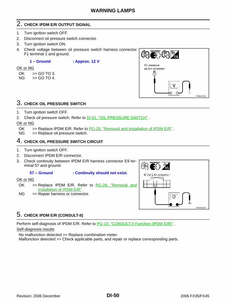
2. CHECK IPDM E/R OUTPUT SIGNAL
1. Turn ignition switch OFF.2. Disconnect oil pressure switch connector.3. Turn ignition switch ON.4. Check voltage between oil pressure switch harness connector
F1 terminal 1 and ground.
OK or NGOK >> GO TO 3.NG >> GO TO 4.
3. CHECK OIL PRESSURE SWITCH
1. Turn ignition switch OFF.2. Check oil pressure switch. Refer to DI-51, "OIL PRESSURE SWITCH" .OK or NGOK >> Replace IPDM E/R. Refer to PG-28, "Removal and Installation of IPDM E/R" .NG >> Replace oil pressure switch.
4. CHECK OIL PRESSURE SWITCH CIRCUIT
1. Turn ignition switch OFF.2. Disconnect IPDM E/R connector.3. Check continuity between IPDM E/R harness connector E9 ter-
minal 57 and ground.
OK or NGOK >> Replace IPDM E/R. Refer to PG-28, "Removal and
Installation of IPDM E/R" .NG >> Repair harness or connector.
5. CHECK IPDM E/R (CONSULT-II)
Perform self-diagnosis of IPDM E/R. Refer to PG-19, "CONSULT-II Function (IPDM E/R)" .Self-diagnosis resultsNo malfunction detected >> Replace combination meter.Malfunction detected >> Check applicable parts, and repair or replace corresponding parts.
1 – Ground : Approx. 12 V
PKIB3573E
57 – Ground : Continuity should not exist.
SKIA5013E

WARNING LAMPS
DI-51
C
D
E
F
G
H
I
J
L
M
A
B
DI
Revision: 2006 December 2006 FX35/FX45
Component Inspection NKS0030G
OIL PRESSURE SWITCHCheck continuity between oil pressure switch and ground.
Condition Oil pressure [kPa (kg/cm2 , psi)] Continuity
Engine stopped Less than 29 (0.3, 4) Yes
Engine running More than 29 (0.3, 4) No
ELF0044D

DI-52
A/T INDICATOR
Revision: 2006 December 2006 FX35/FX45
A/T INDICATOR PFP:24814
System Description NKS003HY
A/T shift position is displayed in the segment display in the combination meter.
MANUAL MODE Unified meter and A/C amp. reads manual mode signal and shift-up/down signal from A/T device (manual
mode switch), and transmits the signals to TCM with CAN communication. TCM processes manual mode signal and shift-up/down signal, and transmits manual mode indicator sig-
nal and shift position indicator signal to unified meter and A/C amp. with CAN communication. Unified meter and A/C amp. transmits manual mode indicator signal and shift position indicator signal to
combination meter with the communication line. Combination meter indicates shift gear position and manual mode indicator, when receiving manual mode
indicator signal and shift position indicator signal.
NOT MANUAL MODE Unified meter and A/C amp. reads not manual mode signal from A/T device (manual mode switch), and
transmits the signals to TCM with CAN communication. TCM transmits shift position indicator signal to unified meter and A/C amp. with CAN communication. Unified meter and A/C amp. transmits shift position indicator signal to combination meter with the commu-
nication line. Combination meter indicates A/T shift position when receiving shift position indicator signal.
SKIB8484E

A/T INDICATOR
DI-53
C
D
E
F
G
H
I
J
L
M
A
B
DI
Revision: 2006 December 2006 FX35/FX45
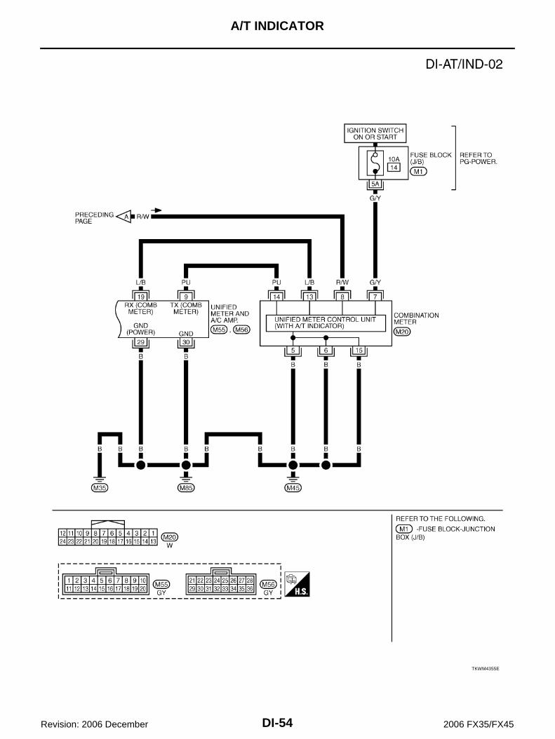
Wiring Diagram — AT/IND — NKS0030H
TKWM4354E
DI-54
A/T INDICATOR
Revision: 2006 December 2006 FX35/FX45
TKWM4355E

A/T INDICATOR
DI-55
C
D
E
F
G
H
I
J
L
M
A
B
DI
Revision: 2006 December 2006 FX35/FX45
A/T Indicator Is Malfunction NKS0030I
1. CHECK SEGMENTS OF A/T INDICATOR
Perform self-diagnosis mode of combination meter. Refer to DI-15,"OPERATION PROCEDURE" .Are all segments displayed?YES >> GO TO 2.NO >> Replace combination meter.
2. CHECK UNIFIED METER AND A/C AMP. (CONSULT-II)
Perform self-diagnosis of unified meter and A/C amp. Refer to DI-31, "CONSULT-II Function (METER A/CAMP)" .Self-diagnosis resultsNo malfunction detected >> GO TO 3.Malfunction detected >> Check applicable parts, and repair or replace corresponding parts.
3. CHECK UNIFIED METER AND A/C AMP. INPUT SIGNAL
1. Select “DATA MONITOR” of “METER A/C AMP” on CONSULT-II. 2. Confirm each indication on the monitor when operating the
selector lever knob.
OK or NGOK >> Replace combination meter.NG >> GO TO 4.
4. CHECK TCM (CONSULT-II)
Perform self-diagnosis of TCM. Refer to AT-90, "CONSULT-II Function (A/T)" .Self-diagnosis resultsNo malfunction detected >> Check TCM input/output signal. Refer to AT-89, "TCM Input/Output Signal Refer-
ence Values" .Malfunction detected >> Check applicable part, and repair or replace corresponding parts.
EL-3828D
CONSULT-II display Switch operationOperation
status
AT-M INDManual mode range ON
Except for manual mode range OFF
AT-M GEARManual mode range (shift- up or down) 5 - 1
Except for manual mode range 1
P RANGE INDP range position ON
Except for P range position OFF
R RANGE INDR range position ON
Except for R range position OFF
N RANGE INDN range position ON
Except for N range position OFF
D RANGE INDD range position ON
Except for D range position OFF
SKIA6259E

DI-56
WARNING CHIME
Revision: 2006 December 2006 FX35/FX45
WARNING CHIME PFP:24814
System Description NKS0030J
Buzzer for warning chime system is installed in the combination meter. The buzzer sounds when the combination meter receives buzzer output signal from each unit through uni-
fied meter and A/C amp.
POWER SUPPLY AND CIRCUITPower is supplied at all times through 50A fusible link (letter M , located in the fuse and fusible link block) to BCM terminal 55, through 15A fuse [No. 22, located in the fuse block (J/B)] to key switch and ignition knob switch terminal 3 (with Intelligent Key) to key switch terminal 2 (without Intelligent Key), and to BCM terminal 42, through 10A fuse [No. 38, located in the fuse and fusible link block (with Intelligent Key)] to key switch and ignition knob switch terminal 1, through 10A fuse [No. 19, located in the fuse block (J/B)] to unified meter and A/C amp. terminal 21, and to combination meter terminal 8.When ignition switch is in ON or START position, power is supplied through 15A fuse [No. 1, located in the fuse block (J/B)] to BCM terminal 38, through 10A fuse [No. 12, located in the fuse block (J/B)] to unified meter and A/C amp. terminal 22, through 10A fuse [No. 14, located in the fuse block (J/B)] to combination meter terminal 7.Ground is supplied to BCM terminals 49 and 52, to unified meter and A/C amp. terminals 29 and 30, and to combination meter terminals 5, 6 and 15 through grounds M35, M45 and M85.

WARNING CHIME
DI-57
C
D
E
F
G
H
I
J
L
M
A
B
DI
Revision: 2006 December 2006 FX35/FX45
IGNITION KEY WARNING CHIME (WITHOUT INTELLIGENT KEY)With the key inserted into the key switch, and the ignition switch in OFF or ACC position, when driver's door isopened, the ignition key warning chime will sound. BCM detects key inserted into the key switch, ignition switch in OFF or ACC position, and front door
switch (driver side) ON. And then transmits buzzer output signal (ignition key warning chime) to unifiedmeter and A/C amp. with CAN communication.
Unified meter and A/C amp. transmits buzzer output signal (ignition key warning chime) to combinationmeter with communication line.
When combination meter receives buzzer output signal (ignition key warning chime), it sounds the buzzer.
IGNITION KEY WARNING CHIME (WITH INTELLIGENT KEY)When Mechanical Key Is UsedWith the key inserted into the ignition switch, and the ignition switch LOCK or ACC position, when driver's dooris opened, the warning chime will sound. BCM detects key inserted into the key switch, ignition switch in LOCK or ACC position, and front door
switch (driver side) ON. And then transmits buzzer output signal (ignition key warning chime) to unifiedmeter and A/C amp. with CAN communication.
Unified meter and A/C amp. transmits buzzer output signal (ignition key warning chime) to combinationmeter with communication line.
When combination meter receives buzzer output signal (ignition key warning chime), it sounds the buzzer.
When Intelligent Key Is Carried With The DriverRefer to BL-91, "WARNING AND ALARM FUNCTION" .
SKIB6481E
SKIB7258E
DI-58
WARNING CHIME
Revision: 2006 December 2006 FX35/FX45
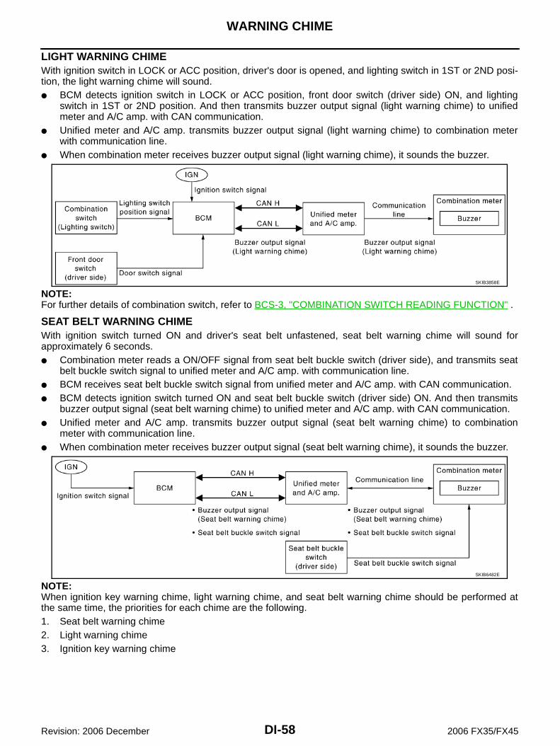
LIGHT WARNING CHIMEWith ignition switch in LOCK or ACC position, driver's door is opened, and lighting switch in 1ST or 2ND posi-tion, the light warning chime will sound. BCM detects ignition switch in LOCK or ACC position, front door switch (driver side) ON, and lighting
switch in 1ST or 2ND position. And then transmits buzzer output signal (light warning chime) to unifiedmeter and A/C amp. with CAN communication.
Unified meter and A/C amp. transmits buzzer output signal (light warning chime) to combination meterwith communication line.
When combination meter receives buzzer output signal (light warning chime), it sounds the buzzer.
NOTE:For further details of combination switch, refer to BCS-3, "COMBINATION SWITCH READING FUNCTION" .
SEAT BELT WARNING CHIMEWith ignition switch turned ON and driver's seat belt unfastened, seat belt warning chime will sound forapproximately 6 seconds. Combination meter reads a ON/OFF signal from seat belt buckle switch (driver side), and transmits seat
belt buckle switch signal to unified meter and A/C amp. with communication line. BCM receives seat belt buckle switch signal from unified meter and A/C amp. with CAN communication. BCM detects ignition switch turned ON and seat belt buckle switch (driver side) ON. And then transmits
buzzer output signal (seat belt warning chime) to unified meter and A/C amp. with CAN communication. Unified meter and A/C amp. transmits buzzer output signal (seat belt warning chime) to combination
meter with communication line. When combination meter receives buzzer output signal (seat belt warning chime), it sounds the buzzer.
NOTE:When ignition key warning chime, light warning chime, and seat belt warning chime should be performed atthe same time, the priorities for each chime are the following.1. Seat belt warning chime2. Light warning chime3. Ignition key warning chime
SKIB3858E
SKIB6482E

WARNING CHIME
DI-59
C
D
E
F
G
H
I
J
L
M
A
B
DI
Revision: 2006 December 2006 FX35/FX45
Component Parts and Harness Connector Location NKS0030M
SKIB8485E

DI-60
WARNING CHIME
Revision: 2006 December 2006 FX35/FX45
Schematic NKS0030N
TKWM4356E

WARNING CHIME
DI-61
C
D
E
F
G
H
I
J
L
M
A
B
DI
Revision: 2006 December 2006 FX35/FX45
Wiring Diagram — CHIME — NKS0030O
TKWM4357E

DI-62
WARNING CHIME
Revision: 2006 December 2006 FX35/FX45
TKWM4358E

WARNING CHIME
DI-63
C
D
E
F
G
H
I
J
L
M
A
B
DI
Revision: 2006 December 2006 FX35/FX45
TKWM4359E

DI-64
WARNING CHIME
Revision: 2006 December 2006 FX35/FX45
Terminals and Reference Value for BCM NKS0030P
CAUTION: Check combination switch system terminal waveform under the loaded condition with lighting
switch, turn signal and wiper switch OFF not to be fluctuated by overloaded. Turn wiper dial position to 4 except when checking waveform or voltage of wiper dial position.
Wiper dial position can be confirmed on CONSULT-II. Refer to LT-119, "DATA MONITOR" .
Ter-minal No.
Wire color
Item
Measuring condition
Reference valueIgnition switch
Operation or condition
2 G/YCombination switch input 5
ON
Lighting, turn, wiper switch(Wiper intermit-tent dial position 4)
OFF Approx. 0 V
Any of the conditions below
Lighting switch 1ST
Lighting switch HIGH beam(Operates only HIGH beam switch)
Turn signal switch to right
Approx. 1.0 V
Lighting switch 2ND
Approx. 2.0 V
3 L/BCombination switch input 4
ON
Lighting, turn, wiper switch(Wiper intermit-tent dial position 4)
OFF Approx. 0 V
Front fog lamp switch (Operates only front fog lamp switch)
Approx. 0.8 V
Any of the conditions below
Lighting switch 2ND
Lighting switch PASSING(Operates only PASSING switch)
Turn signal switch to left
Approx. 1.0 V
4 PU/WCombination switch input 3
ON
Lighting, turn, wiper switch(Wiper intermit-tent dial position 4)
OFF Approx. 0 V
Any of the conditions below
Lighting switch AUTO
Front wiper switch MIST
Front wiper switch INT
Front wiper switch LO
Approx. 1.0 V
PKIB4959J
PKIB4953J
PKIB4955J
PKIB4959J
PKIB4959J

WARNING CHIME
DI-65
C
D
E
F
G
H
I
J
L
M
A
B
DI
Revision: 2006 December 2006 FX35/FX45
5 Y/RCombination switch input 2
ON
Lighting, turn, wiper switch
OFF Approx. 0 V
Any of the conditions below
Front washer switch(Wiper intermittent dial position 4)
Rear washer switch(Wiper intermittent dial position 4)
Wiper intermittent dial position 1
Wiper intermittent dial position 5
Wiper intermittent dial position 6 Approx. 1.0 V
Rear wiper switch ON(Wiper intermittent dial position 4)
Approx. 0.8 V
6 S/BCombination switch input 1
ON
Lighting, turn, wiper switch
OFF Approx. 0 V
Any of the conditions below
Front wiper switch HI(Wiper intermittent dial position 4)
Rear wiper switch INT(Wiper intermittent dial position 4)
Wiper intermittent dial position 3
Approx. 1.0 V
Any of the conditions below
Wiper intermittent dial position 1
Wiper intermittent dial position 2
Approx. 1.7 V
Any of the conditions below
Wiper intermittent dial position 6
Wiper intermittent dial position 7
Approx. 0.8 V
Ter-minal No.
Wire color
Item
Measuring condition
Reference valueIgnition switch
Operation or condition
PKIB4959J
PKIB4955J
PKIB4959J
PKIB4952J
PKIB4955J

DI-66
WARNING CHIME
Revision: 2006 December 2006 FX35/FX45
32 GY/RCombination switch output 5
ON
Lighting, turn, wiper switch
OFF(Wiper intermittent dial position 4)
Approx. 7.2 V
Any of the conditions below
Front fog lamp switch (Operates only front fog lamp switch)
Rear wiper switch ON(Wiper intermittent dial position 4)
Wiper intermittent dial position 1
Wiper intermittent dial position 2
Wiper intermittent dial position 6
Wiper intermittent dial position 7Approx. 1.0 V
33 GCombination switch output 4
ON
Lighting, turn, wiper switch
OFF(Wiper intermittent dial position 4)
Approx. 7.2 V
Any of the conditions below
Lighting switch AUTO (Wiper dial position 4)
Lighting switch 1ST (The same result with lighting switch 2ND) (Wiper intermittent dial position 4)
Rear wiper switch INT(Wiper intermittent dial position 4)
Wiper intermittent dial position 1
Wiper intermittent dial position 5
Wiper intermittent dial position 6
Approx. 1.2 V
Ter-minal No.
Wire color
Item
Measuring condition
Reference valueIgnition switch
Operation or condition
PKIB4960J
PKIB4956J
PKIB4960J
PKIB4958J

WARNING CHIME
DI-67
C
D
E
F
G
H
I
J
L
M
A
B
DI
Revision: 2006 December 2006 FX35/FX45
34 W/BCombination switch output 3
ON
Lighting, turn, wiper switch
OFF
Approx. 7.2 V
Any of the conditions below
Lighting switch 2ND
Lighting switch HI beam(Operates only HI beam switch)
Rear washer switch(Wiper intermittent dial position 4)
Wiper intermittent dial position 1
Wiper intermittent dial position 2
Wiper intermittent dial position 3Approx. 1.2 V
35 W/GCombination switch output 2
ON
Lighting, turn, wiper switch(Wiper intermit-tent dial position 4)
OFF
Approx. 7.2 V
Any of the conditions below
Lighting switch 2ND
Lighting switch PASSING(Operates only PASSING switch)
Front wiper switch INT
Front wiper switch HIApprox. 1.2 V
36 W/RCombination switch output 1
ON
Lighting, turn, wiper switch(Wiper intermit-tent dial position 4)
OFF
Approx. 7.2 V
Any of the conditions below
Turn signal switch to right
Turn signal switch to left
Front wiper switch MIST
Front wiper switch LO
Front washer switchApprox. 1.2 V
Ter-minal No.
Wire color
Item
Measuring condition
Reference valueIgnition switch
Operation or condition
PKIB4960J
PKIB4958J
PKIB4960J
PKIB4958J
PKIB4960J
PKIB4958J

DI-68
WARNING CHIME
Revision: 2006 December 2006 FX35/FX45
Terminals and Reference Value for Unified Meter and A/C Amp. NKS0030Q
37 B/WKey switch sig-nal
OFFKey is removed Approx. 0 V
Key is inserted Battery voltage
38 W/LIgnition power supply
ON — Battery voltage
39 L CAN-H OFF — —
40 P CAN-L OFF — —
42 L/RBattery power supply
OFF — Battery voltage
49B Ground ON — Approx. 0 V
52
55 GBattery power supply
OFF — Battery voltage
62 WFront door switch (Driver side)
OFF
When driver side door is opened (Door switch ON)
Approx. 0 V
When driver side door is closed (Door switch OFF)
Approx. 12 V
Ter-minal No.
Wire color
Item
Measuring condition
Reference valueIgnition switch
Operation or condition
Terminal No.
Wire color
Item
Measuring condition
Reference valueIgnition switch
Operation or condition
1 L CAN-H OFF — —
9 PUTX communication line (To combination meter)
ON —
11 P CAN-L OFF — —
19 L/BRX communication line (From combination meter)
ON —
21 R/W Battery power supply OFF — Battery voltage
22 W Ignition power supply ON — Battery voltage
29B
Ground (Power)ON — Approx. 0 V
30 Ground
SKIA3362E
SKIA3361E
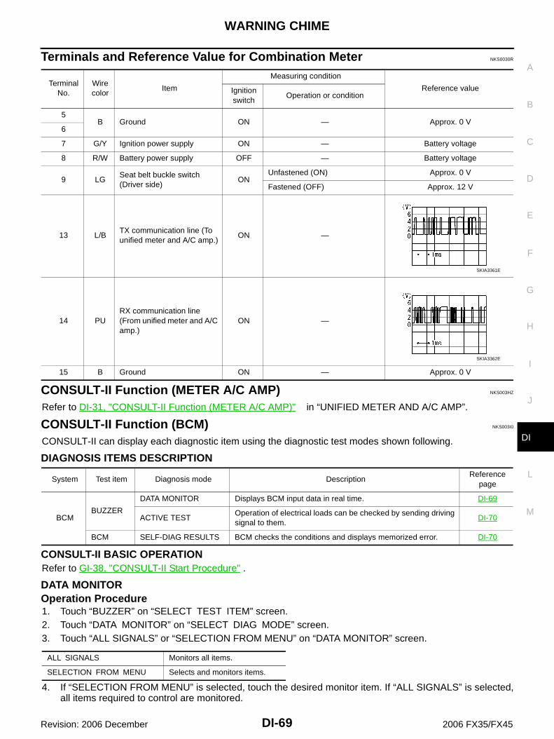
WARNING CHIME
DI-69
C
D
E
F
G
H
I
J
L
M
A
B
DI
Revision: 2006 December 2006 FX35/FX45
Terminals and Reference Value for Combination Meter NKS0030R
CONSULT-II Function (METER A/C AMP) NKS003HZ
Refer to DI-31, "CONSULT-II Function (METER A/C AMP)" in “UNIFIED METER AND A/C AMP”.
CONSULT-II Function (BCM) NKS003I0
CONSULT-II can display each diagnostic item using the diagnostic test modes shown following.
DIAGNOSIS ITEMS DESCRIPTION
CONSULT-II BASIC OPERATIONRefer to GI-38, "CONSULT-II Start Procedure" .
DATA MONITOROperation Procedure1. Touch “BUZZER” on “SELECT TEST ITEM” screen.2. Touch “DATA MONITOR” on “SELECT DIAG MODE” screen.3. Touch “ALL SIGNALS” or “SELECTION FROM MENU” on “DATA MONITOR” screen.
4. If “SELECTION FROM MENU” is selected, touch the desired monitor item. If “ALL SIGNALS” is selected,all items required to control are monitored.
Terminal No.
Wire color
Item
Measuring condition
Reference valueIgnition switch
Operation or condition
5B Ground ON — Approx. 0 V
6
7 G/Y Ignition power supply ON — Battery voltage
8 R/W Battery power supply OFF — Battery voltage
9 LGSeat belt buckle switch (Driver side)
ONUnfastened (ON) Approx. 0 V
Fastened (OFF) Approx. 12 V
13 L/BTX communication line (To unified meter and A/C amp.)
ON —
14 PURX communication line (From unified meter and A/C amp.)
ON —
15 B Ground ON — Approx. 0 V
SKIA3361E
SKIA3362E
System Test item Diagnosis mode DescriptionReference
page
BCMBUZZER
DATA MONITOR Displays BCM input data in real time. DI-69
ACTIVE TESTOperation of electrical loads can be checked by sending driving signal to them.
DI-70
BCM SELF-DIAG RESULTS BCM checks the conditions and displays memorized error. DI-70
ALL SIGNALS Monitors all items.
SELECTION FROM MENU Selects and monitors items.

DI-70
WARNING CHIME
Revision: 2006 December 2006 FX35/FX45
5. Touch “START”.6. During monitoring, touching “RECORD” can start recording the monitored item status.
Display Item List
ACTIVE TESTOperation Procedure1. Touch “BUZZER” on “SELECT TEST ITEM” screen.2. Touch “ACTIVE TEST” on “SELECT DIAG MODE” screen.3. Touch the item to be tested, and check the operation.4. During the operation check, touching “OFF” deactivates the operation.
Display Item List
SELF-DIAG RESULTSOperation Procedure1. Touch “BCM” on “SELECT TEST ITEM” screen.2. Touch “SELF-DIAG RESULTS” on “SELECT DIAG MODE” screen.3. Self-diagnosis results are displayed.
Display Item List
NOTE:If “CAN communication [U1000]” is indicated, after printing the monitor item, go to “LAN system”. Refer toLAN-3, "Precautions When Using CONSULT-II" .
Trouble Diagnosis NKS003I1
HOW TO PERFORM TROUBLE DIAGNOSIS1. Confirm the symptom or customer complaint.2. Understand operation description and function description. Refer to DI-56, "System Description" .3. Perform the preliminary inspection. Refer to DI-71, "PRELIMINARY INSPECTION" .4. Referring to trouble diagnosis chart, make sure the cause of the malfunction and repair or replace applica-
ble parts. Refer to DI-71, "Symptom Chart" .5. Does the warning chime operate normally? If so, GO TO 6. If not, GO TO 3.6. INSPECTION END
Monitored item Description
IGN ON SW Indicates [ON/OFF] condition of ignition switch.
KEY ON SW Indicates [ON/OFF] condition of key switch.
DOOR SW-DR Indicates [ON/OFF] condition of front door switch (driver side).
LIGHT SW 1ST Indicates [ON/OFF] condition of lighting switch.
BUCKLE SW Indicates [ON/OFF] condition of seat belt switch (driver side).
Test item Malfunction is detected when···
LIGHT WARN ALM This test is able to check light warning chime operation.
IGN KEY WARN ALM This test is able to check ignition key warning chime operation.
SEAT BELT WARN TEST This test is able to check seat belt warning chime operation.
Monitored Item CONSULT-ll display Description
CAN communication CAN communication [U1000] Malfunction is detected in CAN communication.

WARNING CHIME
DI-71
C
D
E
F
G
H
I
J
L
M
A
B
DI
Revision: 2006 December 2006 FX35/FX45
PRELIMINARY INSPECTION
1. CHECK BCM (CONSULT-II)
Perform self-diagnosis of BCM. Refer to DI-69, "CONSULT-II Function (BCM)" .Self-diagnosis resultsNo malfunction detected >> GO TO 2.Malfunction detected >> Check applicable parts, and repair or replace corresponding parts.
2. CHECK UNIFIED METER AND A/C AMP. (CONSULT-II)
Perform self-diagnosis of unified meter and A/C amp. Refer to DI-31, "CONSULT-II Function (METER A/CAMP)" .Self-diagnosis resultsNo malfunction detected >> INSPECTION ENDMalfunction detected >> Check applicable parts, and repair or replace corresponding parts.
Symptom Chart NKS003I2
Power Supply and Ground Circuit Inspection NKS003I3
1. CHECK FUSE AND FUSIBLE LINK
Check for blown BCM fuses and fusible link.
OK or NGOK >> GO TO 2.NG >> Be sure to eliminate cause of malfunction before installing new fuse or fusible link. Refer to PG-3,
"POWER SUPPLY ROUTING CIRCUIT" .
Symptom Diagnoses/Service procedure
All warning chimes do not activate.
Perform the following inspections.
1. DI-72, "Combination Meter Buzzer Circuit Inspection".
2. DI-71, "Power Supply and Ground Circuit Inspection".
Replace BCM, found normal function in the above inspections.
Ignition key warning chime does not acti-vate.
Without Intelligent Key.
Perform the following inspections.
1. DI-74, "Front Door Switch (Driver Side) Signal Inspection".
2. DI-75, "Key Switch Signal Inspection (Without Intelligent Key)".
Replace BCM, found normal function in the above inspections.
With Intelligent Key, when mechan-ical key is used.
Perform the following inspections.
1. DI-74, "Front Door Switch (Driver Side) Signal Inspection".
2. DI-76, "Key Switch and Ignition Knob Switch Signal Inspection (With Intelli-gent Key, When Mechanical Key Is Used)".
Replace BCM, found normal function in the above inspections.
With Intelligent Key, when Intelli-gent Key is carried with the driver.
Refer to BL-121, "WARNING CHIME FUNCTION MALFUNCTION" .
Light warning chime does not activate.
Perform the following inspections.
1. DI-74, "Front Door Switch (Driver Side) Signal Inspection".
2. LT-120, "Combination Switch Inspection".
Replace BCM, found normal function in the above inspections.
Seat belt warning chime does not activate.Perform DI-78, "Seat Belt Buckle Switch (Driver Side) Signal Inspection" .Replace BCM, found normal function in the above inspection.
Power source Fuse and fusible link No.
Battery power supplyM
22
Ignition power supply 1

DI-72
WARNING CHIME
Revision: 2006 December 2006 FX35/FX45
2. CHECK POWER SUPPLY CIRCUIT
Check voltage between BCM harness connector terminals andground.
OK or NGOK >> GO TO 3.NG >> Check harness between BCM and fuse.
3. CHECK GROUND CIRCUIT
1. Turn ignition switch OFF. 2. Disconnect BCM connector.3. Check continuity between BCM harness connector M35 terminal
52 and ground.
OK or NGOK >> INSPECTION ENDNG >> Repair harness or connector.
Combination Meter Buzzer Circuit Inspection NKS003I4
1. CHECK OPERATION OF COMBINATION METER BUZZER
1. Select “BUZZER” of “BCM” on CONSULT-ll.2. Perform “LIGHT WARN ALM”, “IGN KEY WARN ALM” or “SEAT
BELT WARN TEST” of “ACTIVE TEST”.Does chime sound?YES >> GO TO 4.NO >> GO TO 2.
Terminals Ignition switch position
(+)(–) OFF ON
Connector Terminal
M34 38
Ground
0 V Battery voltage
M3542
Battery voltage Battery voltage55
PKIB3988E
52 – Ground : Continuity should exist.
PKIB5011E
SKIA6331E

WARNING CHIME
DI-73
C
D
E
F
G
H
I
J
L
M
A
B
DI
Revision: 2006 December 2006 FX35/FX45
2. CHECK UNIFIED METER AND A/C AMP. INPUT SIGNAL
1. Select “METER A/C AMP” on CONSULT-II.2. Operate switches to meet the requirements to sound warning
chime with “BUZZER” of “DATA MONITOR” and check operationstatus.
OK or NGOK >> GO TO 3.NG >> Replace BCM. Refer to BCS-15, "Removal and Installa-
tion of BCM" .
3. CHECK BATTERY POWER SUPPLY CIRCUIT OF COMBINATION METER
Check battery power supply circuit of combination meter. Refer to DI-18, "Power Supply and Ground CircuitInspection" .OK or NGOK >> Replace combination meter.NG >> Check harness between combination meter and fuse.
4. CHECK BATTERY POWER SUPPLY CIRCUIT OF UNIFIED METER AND A/C AMP.
Check battery power supply circuit of unified meter and A/C amp. Refer to DI-33, "Power Supply and GroundCircuit Inspection" .OK or NGOK >> INSPECTION ENDNG >> Check harness between unified meter and A/C amp. and fuse.
“BUZZER”When meeting the requirements to sound warning chime
: ON
Except above : OFF
PKIA2063E

DI-74
WARNING CHIME
Revision: 2006 December 2006 FX35/FX45
Front Door Switch (Driver Side) Signal Inspection NKS003I5
1. CHECK BCM INPUT SIGNAL
With CONSULT-ll1. Select “BCM”.2. With “DATA MONITOR” of “BUZZER”, confirm “DOOR SW-DR”
when the driver side door is operated.
Without CONSULT-llCheck voltage between BCM harness connector B14 terminal 62and ground.
OK or NGOK >> INSPECTION ENDNG >> GO TO 2.
2. CHECK FRONT DOOR SWITCH (DRIVER SIDE) CIRCUIT
1. Turn ignition switch OFF.2. Disconnect BCM connector and front door switch (driver side) connector.3. Check continuity between BCM harness connector B14 terminal
62 and front door switch (driver side) harness connector B26 ter-minal 1.
4. Check continuity between BCM harness connector B14 terminal62 and ground.
OK or NGOK >> GO TO 3.NG >> Repair harness or connector.
3. CHECK FRONT DOOR SWITCH (DRIVER SIDE)
Check front door switch (driver side). Refer to DI-79, "FRONT DOOR SWITCH (DRIVER SIDE)" .OK or NGOK >> Replace BCM. Refer to BCS-15, "Removal and Installation of BCM" .NG >> Replace front door switch (driver side).
“DOOR SW-DR”When driver side door is opened : ONWhen driver side door is closed : OFF
SEL502W
62 – GroundWhen driver side door is opened : Approx. 0 VWhen driver side door is closed : Approx. 12 V
SKIA8220E
62 – 1 : Continuity should exist.
62 – Ground : Continuity should not exist.
SKIA5046E

WARNING CHIME
DI-75
C
D
E
F
G
H
I
J
L
M
A
B
DI
Revision: 2006 December 2006 FX35/FX45
Key Switch Signal Inspection (Without Intelligent Key) NKS003I6
1. CHECK BCM INPUT SIGNAL
With CONSULT-ll1. Select “BCM”.2. With “DATA MONITOR” of “BUZZER”, confirm “KEY ON SW”
when the key is operated.
Without CONSULT-llCheck voltage between BCM harness connector M3 terminal 37 andground.
OK or NGOK >> INSPECTION ENDNG >> GO TO 2.
2. CHECK KEY SWITCH
1. Turn ignition switch OFF.2. Disconnect key switch connector.3. Check key switch. Refer to DI-79, "KEY SWITCH" .OK or NGOK >> GO TO 3.NG >> Replace key switch.
3. CHECK KEY SWITCH CIRCUIT
1. Disconnect BCM connector.2. Check continuity between BCM harness connector M3 terminal
37 and key switch harness connector M23 terminal 1.
3. Check continuity between BCM harness connector M3 terminal37 and ground.
OK or NGOK >> GO TO 4.NG >> Repair harness or connector.
“KEY ON SW”When key is inserted to ignition key cylinder
: ON
When key is removed from ignition key cylinder
: OFF
SKIA1960E
37 – GroundWhen key is inserted to ignition key cylinder
: Approx. 12 V
When key is removed from ignition key cylinder
: Approx. 0 V
SKIA5048E
37 – 1 : Continuity should exist.
37 – Ground : Continuity should not exist.
PKIB3833E

DI-76
WARNING CHIME
Revision: 2006 December 2006 FX35/FX45
4. CHECK KEY SWITCH POWER SUPPLY CIRCUIT
Check voltage between key switch harness connector M23 terminal2 and ground.
OK or NGOK >> Replace BCM. Refer to BCS-15, "Removal and Installa-
tion of BCM" .NG >> Check harness between key switch and fuse.
Key Switch and Ignition Knob Switch Signal Inspection (With Intelligent Key, When Mechanical Key Is Used) NKS003I7
1. CHECK BCM INPUT SIGNAL
With CONSULT-ll1. Select “BCM”.2. With “DATA MONITOR” of “BUZZER”, confirm “KEY ON SW”
when the key is operated.
Without CONSULT-llCheck voltage between BCM harness connector M3 terminal 37 andground.
OK or NGOK >> INSPECTION ENDNG >> GO TO 2.
2. CHECK KEY SWITCH AND IGNITION KNOB SWITCH
1. Turn ignition switch OFF.2. Disconnect key switch and ignition knob switch connector.3. Check key switch and ignition knob switch. Refer to DI-79, "KEY SWITCH AND IGNITION KNOB
SWITCH" .OK or NGOK >> GO TO 3.NG >> Replace key switch and ignition knob switch.
2 – Ground : Battery voltage
SKIA5051E
“KEY ON SW”When key is inserted to ignition key cylinder
: ON
When key is removed from ignition key cylinder
: OFF
SKIA1960E
37 – GroundWhen key is inserted to ignition key cylinder
: Approx. 12 V
When key is removed from ignition key cylinder
: Approx. 0 V
SKIA5048E

WARNING CHIME
DI-77
C
D
E
F
G
H
I
J
L
M
A
B
DI
Revision: 2006 December 2006 FX35/FX45
3. CHECK KEY SWITCH AND IGNITION KNOB SWITCH CIRCUIT
1. Disconnect BCM connector.2. Check continuity between BCM harness connector M3 terminal
37 and key switch and ignition knob switch harness connectorM22 terminal 4.
3. Check continuity between BCM harness connector M3 terminal37 and ground.
OK or NGOK >> GO TO 4.NG >> Repair harness or connector.
4. CHECK KEY SWITCH POWER SUPPLY CIRCUIT
Check voltage between key switch and ignition knob switch harnessconnector M22 terminal 3 and ground.
OK or NGOK >> Replace BCM. Refer to BCS-15, "Removal and Installa-
tion of BCM" .NG >> Check harness between key switch and ignition knob
switch and fuse.
Lighting Switch Signal Inspection NKS003I8
1. CHECK BCM INPUT SIGNAL
1. Select “BCM” on CONSULT-II.2. With “DATA MONITOR” of “BUZZER”, confirm “LIGHT SW 1ST”
when the lighting switch is operated.
OK or NGOK >> INSPECTION ENDNG >> Check the lighting switch. Refer to LT-120, "Combination
Switch Inspection" .
37 – 4 : Continuity should exist.
37 – Ground : Continuity should not exist.
PKIB3578E
3 – Ground : Battery voltage
SKIA5063E
“LIGHT SW 1ST”Lighting switch ON (1st position) : ONLighting switch OFF : OFF
PKIB1956E

DI-78
WARNING CHIME
Revision: 2006 December 2006 FX35/FX45
Seat Belt Buckle Switch (Driver Side) Signal Inspection NKS003I9
1. CHECK UNIFIED METER AND A/C AMP. INPUT SIGNAL
1. Select “METER A/C AMP” on CONSULT-II.2. With “DATA MONITOR” of “METER A/C AMP”, confirm “SEAT
BELT W/L” when the seat belt is operated.
OK or NGOK >> INSPECTION ENDNG >> GO TO 2.
2. CHECK COMBINATION METER INPUT SIGNAL
1. Turn ignition switch ON.2. Check voltage between combination meter harness connector
M20 terminal 9 and ground.
OK or NGOK >> Replace combination meter.NG >> GO TO 3.
3. CHECK SEAT BELT BUCKLE SWITCH (DRIVER SIDE) CIRCUIT
1. Turn ignition switch OFF.2. Disconnect combination meter connector and seat belt buckle switch (driver side) connector.3. Check continuity between combination meter harness connector
M20 terminal 9 and seat belt buckle switch (driver side) harnessconnector B160 terminal 60.
4. Check harness continuity between combination meter harnessconnector M20 terminal 9 and ground.
OK or NGOK >> GO TO 4.NG >> Repair harness or connector.
4. CHECK SEAT BELT BUCKLE SWITCH (DRIVER SIDE)
Check seat belt buckle switch (driver side). Refer to DI-79, "SEAT BELT BUCKLE SWITCH (DRIVER SIDE)" .OK or NGOK >> Check seat belt buckle switch (driver side) ground circuit.NG >> Replace seat belt buckle switch (driver side).
“SEAT BELT W/L”When seat belt (driver side) is fastened
: OFF
When seat belt (driver side) is unfastened
: ON
SKIA6728E
9 – GroundWhen seat belt (driver side) is fastened
: Approx. 12 V
When seat belt (driver side) is unfastened
: Approx. 0 V
SKIA5052E
9 – 60 : Continuity should exist.
9 – Ground : Continuity should not exist.
PKIB3579E

WARNING CHIME
DI-79
C
D
E
F
G
H
I
J
L
M
A
B
DI
Revision: 2006 December 2006 FX35/FX45
Component Inspection NKS003IA
FRONT DOOR SWITCH (DRIVER SIDE)Check continuity between terminal 1 and door switch case ground.
KEY SWITCHCheck continuity between terminals 1 and 2.
KEY SWITCH AND IGNITION KNOB SWITCHCheck continuity between terminals 3 and 4.
SEAT BELT BUCKLE SWITCH (DRIVER SIDE)Check continuity between terminals 60 and 61A.
1 – Front door switch (Driver side) case groundWhen front door switch (driver side) is released
: Continuity should exist.
When front door switch (driver side) is pushed
: Continuity should not exist.
PKIA3718E
1 – 2When key is inserted to igni-tion key cylinder
: Continuity should exist.
When key is removed from ignition key cylinder
: Continuity should not exist.
SKIA5049E
3 – 4When key is inserted to igni-tion key cylinder
: Continuity should exist.
When key is removed from ignition key cylinder
: Continuity should not exist.
SKIA5060E
60 – 61AWhen seat belt (driver side) is fastened
: Continuity should not exist.
When seat belt (driver side) is unfastened
: Continuity should exist.
SKIA5053E

DI-80
LANE DEPARTURE WARNING SYSTEM
Revision: 2006 December 2006 FX35/FX45
LANE DEPARTURE WARNING SYSTEM PFP:28442
Precautions for Lane Departure Warning (LDW) system NKS00311
WARNING:Lane Departure Warning (LDW) is only a warning device to inform the driver of an unintended lanedeparture. It will not steer the vehicle or prevent loss of control. It is the driver's responsibility to stayalert, drive safely, keep the vehicle in the traveling lane, and be in control of the vehicle at all times. LDW system does not operate under the following conditions:– At speeds below approx. 72 km/h (45 MPH).– If it cannot detect lane markers. LDW system may not function properly under the following conditions:– On roads where a water puddle, dirt or snow is covering the lane markers.– On roads where the lane markers are faded or are not painted clearly.– On roads where the lane markers are painted yellow. LDW system may not monitor the lane markers in certain road, weather or driving conditions.– On roads where there are sharp curves.– Where the traveling lane merges or separates.– On roads where the discontinued lane markers are present, such as near tollgates, etc.– On roads where there are not general lane markers.– On roads where the lane width is too narrow.– During bad weather (rain, fog, snow, etc.).– When strong light (for example, at sunrise or sunset) is directly shining on the front of the vehicle.– When entering or exiting a tunnel where sudden changes in brightness occur.– When traveling close to the vehicle in front of you, which causes obstruction of the camera unit
range.– When the vehicle's traveling direction does not align with the lane marker.– When rain, snow or dirt adhere to the windshield in front of the camera unit. Excessive noise interferes with warning system chime sound and the chime may not be heard.CAUTION:To keep the LDW system operating properly, be sure to observe the following: Always keep the windshield clean. The sensing capability of the camera unit depends on the con-
dition of the windshield. See “Appearance and care” for cleaning instruction. Never strike or damage the areas around the camera unit. Never touch the camera lens. Never attach a sticker (including transparent material) or install an accessory near the camera
unit. Never place reflective materials, such as a white paper or mirrors on the instrument panel. Reflec-
tion of the sunlight may adversely affect the camera unit's lane marker detection capability.
System Description NKS00312
LDW SYSTEM OPERATION The Lane Departure Warning (LDW) system warns the driver when the vehicle is traveling close to either
the left or the right of the traveling lane. The system monitors lane markers of the traveling lane using the LDW camera unit. When the LDW cam-
era unit detects that the vehicle is traveling close to either the left or the right of the traveling lane, theLDW indicator lamp flashes and a chime sounds to alert the driver.NOTE:When activating turn signal, LDW system does not give a warning to the lane marker on the turn signalside.
The LDW system can be turned on or off by pushing the LDW switch. When the system is on, the LDWsystem ON indicator illuminates.
The LDW system has an automatic mode and manual mode.

LANE DEPARTURE WARNING SYSTEM
DI-81
C
D
E
F
G
H
I
J
L
M
A
B
DI
Revision: 2006 December 2006 FX35/FX45
In the automatic mode– LDW system automatically turns on, when the ignition switch is turned to the ON position. – LDW system ON indicator located on the LDW switch illuminates, indicating that the system is on.– To cancel LDW system, push the LDW switch to turn off LDW system ON indicator. – To turn on the system, push LDW switch again.In the manual mode– LDW system is still off when the ignition switch is turned to the ON position.– The LDW switch must be pushed to turn on the system.To the change modes– Push and hold LDW switch for more than 4 seconds, when LDW system ON indicator is off.– Then LDW chime sounds and blinking of LDW system ON indicator informs that the mode change is com-
pleted. Temporary disabled status at high temperature– If the vehicle is parked in direct sunlight under high temperature conditions [approximately over 104°F
(40°C)] and then started, the LDW system may sound a chime and cancel automatically. Then LDW sys-tem ON indicator will blink.
– When the interior temperature is reduced, the system will resume to operate automatically and the LDWsystem ON indicator illuminates.
Warning Function
SKIB1783E

DI-82
LANE DEPARTURE WARNING SYSTEM
Revision: 2006 December 2006 FX35/FX45
System Diagram
Components Description
NOTE:*: This indicates in a few seconds for the system check during ignition switch ON.
POWER SUPPLY AND GROUND CIRCUITWith the ignition switch in the ON or START position, power is supplied through 10A fuse [No. 12, located in the fuse block (J/B)] to LDW camera unit terminal 1.Ground is supplied to LDW camera unit terminals 6 and 12 through grounds M45, M85 and M35.
SKIB1784E
Component Description
LDW camera unitDetects the lane marker by the built-in camera, gives judgement for the warning according to the result of detection and signals from each unit, and transmits the operation signal to LDW chime and LDW indicator lamp.
LDW switch Selects ON/OFF of the system.
Indicates ON/OFF of the signal with LDW system ON indicator.
LDW chime Gives a warning chime according to the direction from LDW camera unit.
LDW indicator lamp
Installed in combination meter, and indicates the system condition.
Blinks when LDW system is functioning to alert the driver.
Stays on when LDW system is malfunctioning.*
BCM Transmits turn indicator signal to LDW camera unit with CAN communication signal.
ABS actuator and electric unit (control unit)
Transmits vehicle speed signal to LDW camera unit with CAN communication signal.
TCM Transmits vehicle speed signal to LDW camera unit with CAN communication signal. (For detecting incorrect speed.)

LANE DEPARTURE WARNING SYSTEM
DI-83
C
D
E
F
G
H
I
J
L
M
A
B
DI
Revision: 2006 December 2006 FX35/FX45
Action Test NKS00314
LDW SYSTEM RUNNING TESTWARNING: Be careful when performing road test. Understand “Precautions” and “System Description” well before the road test. Refer to DI-80,
"Precautions for Lane Departure Warning (LDW) system" and DI-80, "System Description" .
Function CheckCheck the LDW system operation according to the condition that the warning function works. Refer to DI-80,"LDW SYSTEM OPERATION" .
Camera Aiming Adjustment NKS00315
OUTLINEAdjust the camera aiming every time the LDW camera unit is removed or installed.CAUTION: Place the vehicle on the level ground when the camera aiming adjustment is operated. Follow the CONSULT-II when adjusting the camera aiming. (Camera aiming adjustment cannot be
operated without CONSULT-II.)
PREPARATION Keep all tires inflated to correct pressures. Adjust the tire pressure to the specified pressure value. There is no-load in vehicle. Check if coolant, engine oil are filled up to correct level and fuel tank is full. Shift the gear into “P” position and release the parking brake. Clean the windshield.NOTE:Do not place anything reflective on the upper surface of instrument panel.
TARGET SETTINGPreparation Aiming Adjustment JigFor aiming adjustment, prepare the following jigs and targets.
PKIB4693E

DI-84
LANE DEPARTURE WARNING SYSTEM
Revision: 2006 December 2006 FX35/FX45
TargetNOTE:Enlarge this page to 122% size and print it out.
PGIA0105J

LANE DEPARTURE WARNING SYSTEM
DI-85
C
D
E
F
G
H
I
J
L
M
A
B
DI
Revision: 2006 December 2006 FX35/FX45
Target SettingCAUTION: Perform this operation in a horizontal position where there is a clear view for 5 m (16.4 ft) forward
and 3 m (9.84 ft) wide. Place the target at a well-lighted location. (Poor lighting may make it hard to adjust.) The target may not be detected when there is a light source within 1.5 m (4.92 ft) from either side
and within 1 m (3.28 ft) upward/downward from the target. Make sure location of the sun. (Sunlight should not shine directly on front of the vehicle.) The target may not be detected when there is the same pattern of black and white as the target
when the pattern is within 1 m (3.28 ft) from either side and upward/downward position from thetarget. (It is desirable that the vehicle is positioned on the opposite side of a single-color wall.)
1. Mark a point at the center of lateral surface of each wheels (“A”,“B”, “C” and “D”).NOTE:Dangle a string with a cone from the fender so as to passthrough the center of wheel, and then mark a point at the centerof lateral surface of wheels.
2. Draw a line passing through points “A” and “B” on the left side ofvehicle (line “LH”). NOTE:Approximately 4 m (13.12 ft) or more from the forward end ofvehicle.
3. Mark points on the line “LH”, at the positions 3850 mm (151.57 in) from the point “A” (“E”).4. Draw a line passing through the points “C” and “D” on the right side of vehicle as with the step 2 (line
“RH”).NOTE:Approximately 4 m (13.12 ft) or more from the forward end of vehicle.
5. Mark points on the line “RH”, at the positions 3850 mm (151.57 in) from the point “C” (“F”).6. Draw a line passing through the points “E” and “F” (line “FW”).
PKIB4694E
PKIB4695E
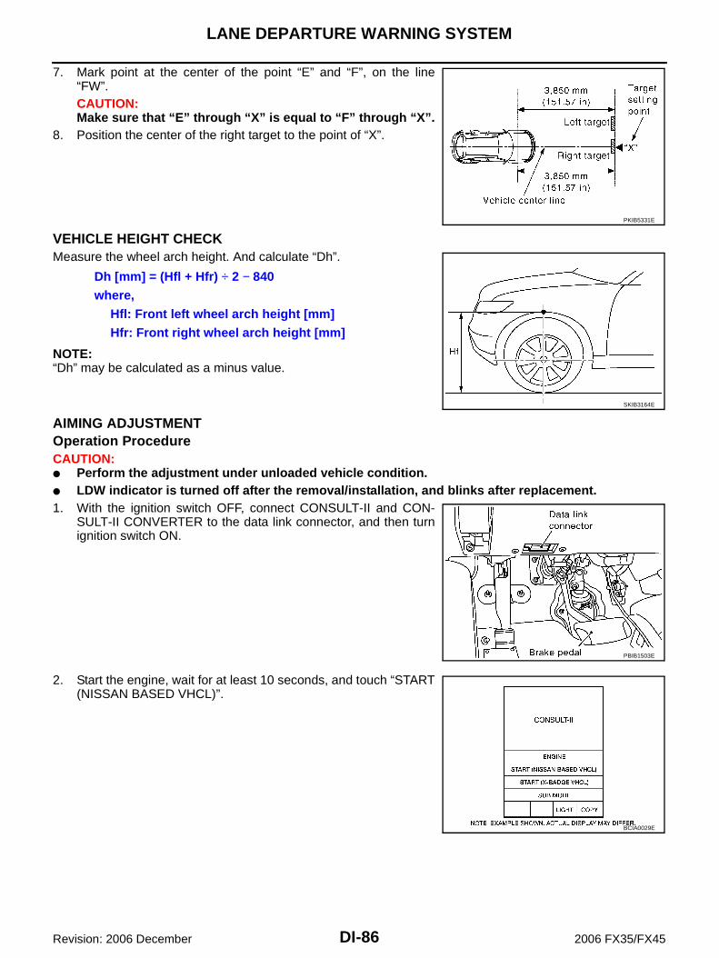
DI-86
LANE DEPARTURE WARNING SYSTEM
Revision: 2006 December 2006 FX35/FX45
7. Mark point at the center of the point “E” and “F”, on the line“FW”.CAUTION:Make sure that “E” through “X” is equal to “F” through “X”.
8. Position the center of the right target to the point of “X”.
VEHICLE HEIGHT CHECKMeasure the wheel arch height. And calculate “Dh”.
NOTE:“Dh” may be calculated as a minus value.
AIMING ADJUSTMENTOperation Procedure CAUTION: Perform the adjustment under unloaded vehicle condition. LDW indicator is turned off after the removal/installation, and blinks after replacement.1. With the ignition switch OFF, connect CONSULT-II and CON-
SULT-II CONVERTER to the data link connector, and then turnignition switch ON.
2. Start the engine, wait for at least 10 seconds, and touch “START(NISSAN BASED VHCL)”.
PKIB5331E
Dh [mm] = (Hfl + Hfr) ÷ 2 − 840where,
Hfl: Front left wheel arch height [mm]Hfr: Front right wheel arch height [mm]
SKIB3164E
PBIB1503E
BCIA0029E
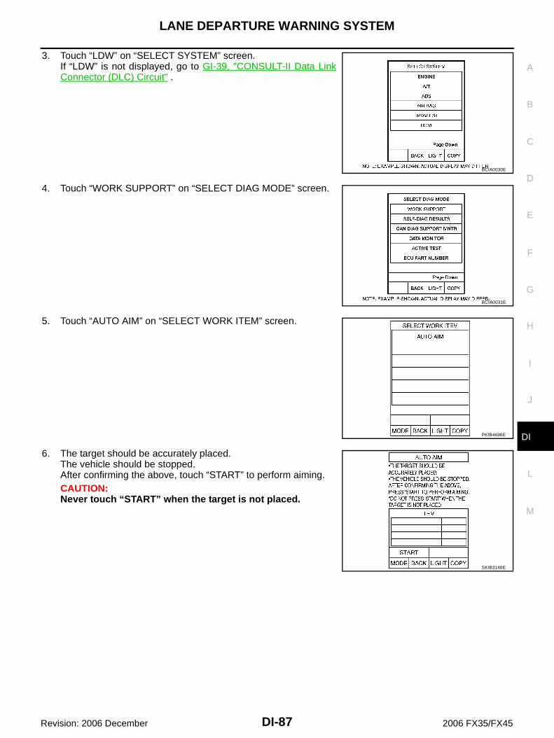
LANE DEPARTURE WARNING SYSTEM
DI-87
C
D
E
F
G
H
I
J
L
M
A
B
DI
Revision: 2006 December 2006 FX35/FX45
3. Touch “LDW” on “SELECT SYSTEM” screen.If “LDW” is not displayed, go to GI-39, "CONSULT-II Data LinkConnector (DLC) Circuit" .
4. Touch “WORK SUPPORT” on “SELECT DIAG MODE” screen.
5. Touch “AUTO AIM” on “SELECT WORK ITEM” screen.
6. The target should be accurately placed.The vehicle should be stopped.After confirming the above, touch “START” to perform aiming.CAUTION:Never touch “START” when the target is not placed.
BCIA0030E
BCIA0031E
PKIB4696E
SKIB3146E
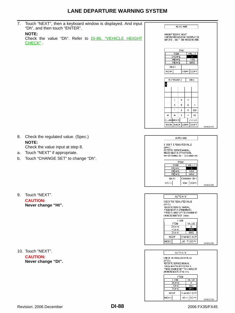
DI-88
LANE DEPARTURE WARNING SYSTEM
Revision: 2006 December 2006 FX35/FX45
7. Touch “NEXT”, then a keyboard window is displayed. And input“Dh”, and then touch “ENTER”.NOTE:Check the value “Dh”. Refer to DI-86, "VEHICLE HEIGHTCHECK" .
8. Check the regulated value. (Spec.)NOTE:Check the value input at step 8.
a. Touch “NEXT” if appropriate.b. Touch “CHANGE SET” to change “Dh”.
9. Touch “NEXT”.CAUTION:Never change “Ht”.
10. Touch “NEXT”.CAUTION:Never change “Dt”.
SKIB3147E
SKIB3148E
SKIB3149E
SKIB3173E

LANE DEPARTURE WARNING SYSTEM
DI-89
C
D
E
F
G
H
I
J
L
M
A
B
DI
Revision: 2006 December 2006 FX35/FX45
11. Touch “START”.
12. Check it display item.a. “NORMALLY COMPLETED” is displayed, then touching “COM-
PLETION”.
b. Perform the following services when displayed “SUSPENSION”or “ABNORMALLY COMPLETED”.
NOTE:Replace camera unit if “suspension” is repeatedly indicated though the above two service is performed.
13. Check if “NORMALLY COMPLETED” is displayed and close theaiming adjustment procedure by touching “END”.
SKIB3150E
SKIB3151E
SKIB3152E
Displays item Service procedure
SUSPENSION00H Routine not activated
Position the target appropriately again. Perform the aiming again. Refer to DI-83, "Camera Aiming Adjustment" .
10H Writing error
ABNORMALLY COMPLETED —
SKIB3153E

DI-90
LANE DEPARTURE WARNING SYSTEM
Revision: 2006 December 2006 FX35/FX45
Check After The Adjustment1. Perform the LDW camera unit self-diagnosis. Refer to DI-95, "CONSULT-II Function (LDW)" .2. Test the LDW system operation by running test. Refer to DI-83, "LDW SYSTEM RUNNING TEST" .
Component Parts and Harness Connector Location NKS00316
SKIB8486E

LANE DEPARTURE WARNING SYSTEM
DI-91
C
D
E
F
G
H
I
J
L
M
A
B
DI
Revision: 2006 December 2006 FX35/FX45
Schematic NKS00317
TKWM4366E

DI-92
LANE DEPARTURE WARNING SYSTEM
Revision: 2006 December 2006 FX35/FX45
Wiring Diagram — LDW — NKS00318
TKWM4367E

LANE DEPARTURE WARNING SYSTEM
DI-93
C
D
E
F
G
H
I
J
L
M
A
B
DI
Revision: 2006 December 2006 FX35/FX45
TKWM4368E

DI-94
LANE DEPARTURE WARNING SYSTEM
Revision: 2006 December 2006 FX35/FX45
TKWM4369E

LANE DEPARTURE WARNING SYSTEM
DI-95
C
D
E
F
G
H
I
J
L
M
A
B
DI
Revision: 2006 December 2006 FX35/FX45
Terminals and Reference Value for LDW Camera Unit NKS00319
NOTE:*: Perform “ACTIVE TEST” with CONSULT-II. Refer to DI-97, "ACTIVE TEST" .
CONSULT-II Function (LDW) NKS0031A
DESCRIPTIONCONSULT-II performs the following functions communicating with the LDW camera unit.
CONSULT-II BASIC OPERATIONRefer to GI-38, "CONSULT-II Start Procedure" .
WORK SUPPORTOperation ProcedureTouch “WORK SUPPORT” on “SELECT DIAG MODE” screen.
Display Item
SELF-DIAG RESULTSOperation Procedure1. Touch “SELF-DIAG RESULTS” on “SELECT DIAG MODE” screen.2. See the displayed result of self-diagnosis.
Terminal No.
Wire Color
Item
ConditionReference Value
(Approx. [V])Ignition switch
Operation or condition
1 B/R Ignition power supply ON — Battery voltage
3 R/W LDW chime ON LDW chimeActivated* 0
Not activated 12
4 Y System ON indicator ON LDW systemON 0
OFF 12
5 R CAN-L — — —
6 B Ground ON — 0
8 G/W LDW indicator lamp ON LDW indicator lamp Illuminated* 0
Turned OFF 12
9 G LDW switch ON LDW switchPressed 0
Released 5
10 L CAN-H — — —
11 — Shield — — —
12 B Ground ON — 0
Select diag mode Function Reference page
WORK SUPPORT Displays causes of automatic cancellation of the LDW system. DI-95
SELF-DIAG RESULTS Displays malfunctioning system memorized in LDW camera unit. DI-95
DATA MONITOR Displays real-time input/output data of LDW camera unit. DI-96
CAN DIAG SUPPORT MNTR The results of transmit/receive diagnosis of CAN communication can be read. LAN-3
ACTIVE TEST Enables operation check of electrical loads by sending driving signal to them. DI-97
ECU PART NUMBER Displays part number of LDW camera unit. —
Operation Function Reference page
AUTO AIMOutputs camera unit, calculates dislocation of the camera, and displays adjustment direction.
DI-83

DI-96
LANE DEPARTURE WARNING SYSTEM
Revision: 2006 December 2006 FX35/FX45
Display Item
NOTE: When a DTC is detected, the LDW system dose not operate.
When the DTC except “ABNRML TEMP DETECT [C1B03] ” is detected, the LDW indicator lamp turns ON.
When the DTC “ABNRML TEMP DETECT [C1B03] ” is detected, the LDW system ON indicator lamp blinks.
DATA MONITOROperation Procedure1. Touch “DATA MONITOR” on “SELECT DIAG MODE” screen.2. Touch any of “ALL SIGNALS” and “SELECTION FROM MENU” on selection screen.3. Touch “START”.4. Display the data monitor.5. If necessary, touch “COPY” in turn, and print data.
Monitored Item
Display item [Code] Malfunctions detected where...Reference
page
CAMERA UNIT MALF [C1B00] LDW camera unit internal malfunction DI-100
CAM AIMING INCMP [C1B01] LDW camera aiming is not adjusted. DI-100
VHCL SPD DATA MALF [C1B02]LDW camera unit detected different vehicle speed signal from TCM and ABS actuator and electric unit (control unit).
DI-100
ABNRML TEMP DETECT [C1B03] Temperature around LDW camera unit is excessively high. DI-101
CAN COMM CIRCUIT [U1000] LDW camera unit detected CAN communication malfunction. DI-101
CONTROL UNIT (CAN) [U1010] LDW camera unit detected internal CAN communication circuit malfunction. DI-101
Monitored Item [unit] Description
MAIN SW [ON/OFF] Displays [ON/OFF] status as judged from LDW switch signal.
SW ON LAMP [ON/OFF] Displays [ON/OFF] status of LDW system ON indicator signal output.
INDICATE LAMP [ON/OFF] Displays [ON/OFF] status of LDW indicator signal output.
BUZZER OUTPUT [ON/OFF] Displays [ON/OFF] status of LDW chime operation signal output.
LDW INACCURAT [ON/OFF] Displays LDW camera unit status.
VHCL SPD SE [km/h] or [mph]Displays vehicle speed calculated by LDW camera unit through CAN communication [ABS actuator and electric unit (control unit) transmits wheel sensor signal through CAN commu-nication].
VHCL SPD AT [km/h] or [mph]Displays vehicle speed calculated from A/T vehicle speed sensor by LDW camera unit through CAN communication (TCM transmits A/T vehicle speed sensor signal through CAN communication).
TURN SIGNAL [OFF/LH/RH] Displays “Turn signal” status, determined from BCM through CAN communication.
LANE DETCT LH [ON/OFF] Displays left lane marker is detected.
LANE DETCT RH [ON/OFF] Displays right lane marker is detected.
CROSS LANE LH [ON/OFF] Displays vehicle is crossing left lane.
CROSS LANE RH [ON/OFF] Displays vehicle is crossing right lane.
WARN LANE LH [ON/OFF] Displays warning for left lane.
WARN LANE RH [ON/OFF] Displays warning for right lane.
VALID POS LH [VLD/INVLD] Displays lateral position for left lane marker is valid.
VALID POS RH [VLD/INVLD] Displays lateral position for right lane marker is valid.
AIMING DONE [OK/NG] Displays camera aiming done.
AIMING RESULT [OK/NOK] Displays camera aiming result.
FCTRY AIM YAW [deg] Displays camera unit installation condition.
FCTRY AIM ROL [deg] Displays camera unit installation condition.

LANE DEPARTURE WARNING SYSTEM
DI-97
C
D
E
F
G
H
I
J
L
M
A
B
DI
Revision: 2006 December 2006 FX35/FX45
ACTIVE TESTCAUTION: Never perform the active test while driving. Active test cannot be started while LDW indicator lamp is illuminated.1. Touch “ACTIVE TEST” on “SELECT DIAG MODE” screen. Refer to DI-95, "CONSULT-II BASIC OPERA-
TION" .2. Touch any field, “BUZZER DRIVE ”, “SYSTEM ON LAMP DRIVE” and “INDICATOR LAMP DRIVE”, on
selection screen.3. Touch necessary item and “START”.4. Active test screen will be shown.
Active Test Item
BUZZER DRIVETouch “ON” and “OFF” to check if LDW chime operates as follows.
SYSTEM ON LAMP DRIVETouch “ON” and “OFF” to check if LDW system ON indicator oper-ates as follows.
NOTE:Perform “SYSTEM ON LAMP DRIVE” when LDW system ON indica-tor turns OFF.
FCTRY AIM PIT [deg] Displays camera unit installation condition.
XOFFSET [pixel] Displays camera unit installation condition.
Monitored Item [unit] Description
Active test item Operation item FunctionReference
page
BUZZER DRIVE LDW chime This test is able to check LDW chime operation. DI-97
SYSTEM ON LAMP DRIVELDW system ON indicator
This test is able to check LDW system ON indicator operation.
DI-97
INDICATOR LAMP DRIVE LDW indicator lamp This test is able to check LDW indicator lamp operation. DI-98
“BUZZER DRIVE”Touch “ON” : LDW chime is activated.Touch “OFF” : LDW chime is not activated.
SKIB1787E
“SYSTEM ON LAMP DRIVE”Touch “ON” : LDW system ON indicator illuminates.Touch “OFF” : LDW system ON indicator turns OFF.
SKIB1788E

DI-98
LANE DEPARTURE WARNING SYSTEM
Revision: 2006 December 2006 FX35/FX45
INDICATOR LAMP DRIVETouch “ON” and “OFF” to check that LDW indicator lamp operates asfollows.
Trouble Diagnosis NKS0031B
HOW TO PERFORM TROUBLE DIAGNOSIS1. Check the symptom and customer complaint.2. Understand the outline of system. Refer to DI-80, "System Description" .3. Perform the preliminary inspection. Refer to DI-98, "Preliminary Inspection" .4. Referring to symptom chart, repair or replace the cause of the malfunction. Refer to DI-98, "SYMPTOM
CHART" .5. Erase DTC and perform self-diagnosis of LDW system again. Then perform LDW system running test.
Refer to DI-95, "CONSULT-II Function (LDW)" and DI-83, "LDW SYSTEM RUNNING TEST" .6. Does LDW system operate normally? If it operates normally, GO TO 7. If not, GO TO 3.7. INSPECTION END
SYMPTOM CHART
Preliminary Inspection NKS0031C
1. CHECK CAMERA LENS AND WINDSHIELD
Are camera lens and windshield contaminated with foreign materials? YES >> Clean camera lens and windshield.NO >> GO TO 2.
“INDICATOR LAMP DRIVE”Touch “ON” : LDW indicator lamp illuminates.Touch “OFF” : LDW indicator lamp OFF.
PKIB4692E
Symptom Diagnoses/Service procedure
LDW system is not activated.(LDW system ON indicator turns ON/OFF.)
Perform the following inspections.
1. DI-101, "LDW Chime Circuit Inspection"
2. DI-105, "LDW Indicator Lamp Circuit Inspection"
Replace LDW camera unit, check function in the above inspections.
LDW system does not turn ON/OFF.(LDW system ON indicator does not turn ON/OFF.)
Perform DI-102, "LDW Switch Circuit Inspection" .Replace LDW camera unit, check function in the above inspection.
Warning functions are untimely.
(Example)
Warning does not function when driving on lane markers.
Warning functions when driving in a lane.
Different position from actual condition functions.
Perform DI-83, "Camera Aiming Adjustment" .
Functions when changing the course to the turn signal direc-tion.
Perform DI-106, "Turn Signal Input Inspection" .Replace LDW camera unit, check function in the above inspection.
LDW indicator lamp does not illuminate with ignition switch ON.Perform DI-105, "LDW Indicator Lamp Circuit Inspection" .Replace LDW camera unit, check function in the above inspection.

LANE DEPARTURE WARNING SYSTEM
DI-99
C
D
E
F
G
H
I
J
L
M
A
B
DI
Revision: 2006 December 2006 FX35/FX45
2. CHECK CAMERA UNIT INSTALLATION CONDITION
Check camera unit installation condition (installation position, properly tightened, a bent bracket). OK or NGOK >> GO TO 3.NG >> Install camera unit properly, and adjust camera aiming. Refer to DI-83, "Camera Aiming Adjust-
ment" .
3. CHECK VEHICLE HEIGHT
Check vehicle height. Refer to GI-51, "Dimensions" .Is vehicle height appropriate?OK >> GO TO 4.NG >> Repair vehicle to appropriate height.
4. CHECK LDW CAMERA UNIT (CONSULT-II)
Perform self-diagnosis of LDW camera unit. Refer to DI-95, "CONSULT-II Function (LDW)" .Self-diagnosis resultsNo malfunction detected >> GO TO 5.Malfunction detected >> Check applicable parts, and repair or replace corresponding parts.
5. CHECK COMBINATION METER
Check combination meter function.Do speedometer and turn signal indicator normal function?YES >> INSPECTION ENDNO >> Check combination meter. Refer to DI-16, "Trouble Diagnosis" .
Power Supply and Ground Circuit Inspection NKS0031D
1. CHECK FUSE
Check for blown LDW camera unit fuse.
OK or NGOK >> GO TO 2.NG >> Be sure to eliminate cause of malfunction before installing new fuse. Refer to PG-81, "FUSE
BLOCK - JUNCTION BOX (J/B)" .
2. CHECK POWER SUPPLY CIRCUIT
Check voltage between LDW camera unit and ground.
OK or NGOK >> GO TO 3.NG >> Check harness between LDW camera unit and fuse.
Power source Fuse No.
Ignition power supply 12
Terminals Ignition switch position
(+)(–) OFF ON
Connector Terminal
R9 1 Ground 0 V Battery voltage
PKIC0246E

DI-100
LANE DEPARTURE WARNING SYSTEM
Revision: 2006 December 2006 FX35/FX45
3. CHECK GROUND CIRCUIT
1. Turn ignition switch OFF.2. Disconnect LDW camera unit connector.3. Check continuity between LDW camera unit harness connector
R9 terminals 6, 12 and ground.
OK or NGOK >> INSPECTION ENDNG >> Repair ground harness.
DTC [C1B00] CAMERA UNIT MALF NKS0031E
1. CHECK LDW CAMERA UNIT
1. Perform self-diagnosis of LDW camera unit.2. Check if any item other than “[C1B00] CAMERA UNIT” is displayed on self-diagnosis display.Is any displayed?YES >> Repair or replace applicable item.NO >> Replace LDW camera unit.
DTC [C1B01] CAM AIMING INCMP NKS0031F
1. PREFORM CAMERA AIMING ADJUSTMENT
1. Preform camera aiming adjustment. Refer to DI-83, "Camera Aiming Adjustment" .2. Erase DTC and perform the LDW camera unit self-diagnosis.Self-diagnosis resultsNo malfunction detected >> INSPECTION ENDMalfunction detected >> Replace LDW camera unit.
DTC [C1B02] VHCL SPD DATA MALF NKS0031G
1. CHECK ABS ACTUATOR AND ELECTRIC UNIT (CONTROL UNIT) (CONSULT-II)
Perform self-diagnosis of ABS actuator and electric unit (control unit). Refer to BRC-24, "CONSULT-II Func-tions (VDC)" .Self-diagnosis resultsNo malfunction detected >> GO TO 2.Malfunction detected >> Check applicable parts, and repair or replace corresponding parts.
2. CHECK TCM (CONSULT-II)
Perform self-diagnosis of TCM. Refer to AT-90, "CONSULT-II Function (A/T)" .Self-diagnosis resultsNo malfunction detected >> Replace LDW camera unit.Malfunction detected >> Check applicable parts, and repair or replace corresponding parts.
6 – Ground: Continuity should exist.
12 – Ground
PKIC0247E

LANE DEPARTURE WARNING SYSTEM
DI-101
C
D
E
F
G
H
I
J
L
M
A
B
DI
Revision: 2006 December 2006 FX35/FX45
DTC [C1B03] ABNRML TEMP DETECT NKS0031H
1. COOLING CAMERA UNIT
1. Cooling camera unit.2. Erase DTC and perform the LDW camera unit self-diagnosis.Self-diagnosis resultsNo malfunction detected >> INSPECTION ENDMalfunction detected >> Replace LDW camera unit.
DTC [U1000] CAN COMM CIRCUIT NKS0031I
1. CHECK CAN COMMUNICATION
1. Select “SELF-DIAG RESULTS” mode for “LDW” with CONSULT-II.2. Print out CONSULT-II screen.
>> Go to “LAN SYSTEM”. Refer to LAN-3, "Precautions When Using CONSULT-II" .
DTC [U1010] CONTROL UNIT (CAN) NKS0031J
Replace LDW camera unit, when “[U1010] CONTROL UNIT (CAN)” is displayed on self-diagnosis display.
LDW Chime Circuit Inspection NKS0031K
1. CHECK LDW CHIME OPERATION
Check LDW chime operation “BUZZER DRIVE” in “ACTIVE TEST”mode with CONSULT-II.
OK or NGOK >> INSPECTION ENDNG >> GO TO 2.
2. CHECK LDW CHIME POWER SUPPLY CIRCUIT
1. Turn ignition switch OFF.2. Disconnect LDW chime connector.3. Turn ignition switch ON.4. Check voltage between warning chime harness connector M97
terminal 1 and ground.
OK or NGOK >> GO TO 3.NG >> Check harness between fuse and LDW chime.
“BUZZER DRIVE”Touch “ON” : LDW chime is activated.Touch “OFF” : LDW chime is not activated.
SKIB1787E
1 – Ground : Battery voltage
PKIC0248E

DI-102
LANE DEPARTURE WARNING SYSTEM
Revision: 2006 December 2006 FX35/FX45
3. CHECK LDW CHIME GROUND CIRCUIT
1. Turn ignition switch OFF.2. Check continuity between LDW chime harness connector M97
terminal 3 and ground.
OK or NGOK >> GO TO 4.NG >> Repair harness or connector.
4. CHECK LDW CHIME SIGNAL CIRCUIT
1. Disconnect LDW camera unit connector.2. Check continuity between LDW camera unit harness connector
(A) R9 terminal 3 and LDW chime harness connector (B) M97terminal 2.
3. Check continuity between LDW camera unit harness connector(A) R9 terminal 3 and ground.
OK or NGOK >> GO TO 5.NG >> Repair harness or connector.
5. CHECK LDW CHIME OPERATION
1. Connect LDW chime connector.2. Turn ignition switch ON.3. Apply ground to LDW chime terminal 2.4. Check condition of the LDW chime.
OK or NGOK >> Replace LDW camera unit.NG >> Replace LDW chime.
LDW Switch Circuit Inspection NKS0031L
1. CHECK OPERATION OF LDW SYSTEM ON INDICATOR
1. Turn ignition switch ON.2. Check LDW system ON indicator operation when LDW switch is ON/OFF.OK or NGOK >> INSPECTION ENDNG >> GO TO 2.
3 – Ground : Continuity should exist.
PKIC0249E
3 – 2 : Continuity should exist.
3 – Ground : Continuity should not exist.
SKIB8694E
2 – Ground : LDW chime should operate.
PKIC0251E

LANE DEPARTURE WARNING SYSTEM
DI-103
C
D
E
F
G
H
I
J
L
M
A
B
DI
Revision: 2006 December 2006 FX35/FX45
2. CHECK LDW SWITCH SIGNAL INPUT
Check voltage between LDW camera unit harness connector R9 ter-minal 9 and ground.
OK or NGOK >> GO TO 6.NG >> GO TO 3.
3. CHECK LDW SWITCH GROUND CIRCUIT
1. Turn ignition switch OFF.2. Disconnect LDW switch connector.3. Check continuity between LDW switch connector M96 terminal 6
and ground.
OK or NGOK >> GO TO 4.NG >> Repair harness or connector.
4. CHECK LDW SWITCH SIGNAL INPUT CIRCUIT
1. Disconnect LDW camera unit connector.2. Check continuity between LDW camera unit harness connector
R9 terminal 9 and LDW switch harness connector M96 terminal7.
3. Check continuity between LDW camera unit harness connectorR9 terminal 9 and ground.
OK or NGOK >> GO TO 5.NG >> Repair harness or connector.
5. CHECK LDW SWITCH
Check LDW switch. Refer to OK or NGOK >> Replace LDW camera unit.NG >> Replace LDW switch.
9 – GroundWhen LDW switch is pressed : Approx. 0 VWhen LDW switch is released : Approx. 5 V
PKIC0252E
6 – Ground : Continuity should exist.
PKIB4702E
9 – 7 : Continuity should exist.
9 – Ground : Continuity should not exist.
PKIB4703E
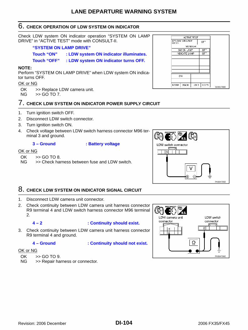
DI-104
LANE DEPARTURE WARNING SYSTEM
Revision: 2006 December 2006 FX35/FX45
6. CHECK OPERATION OF LDW SYSTEM ON INDICATOR
Check LDW system ON indicator operation “SYSTEM ON LAMPDRIVE” in “ACTIVE TEST” mode with CONSULT-II.
NOTE:Perform “SYSTEM ON LAMP DRIVE” when LDW system ON indica-tor turns OFF.OK or NGOK >> Replace LDW camera unit.NG >> GO TO 7.
7. CHECK LDW SYSTEM ON INDICATOR POWER SUPPLY CIRCUIT
1. Turn ignition switch OFF.2. Disconnect LDW switch connector.3. Turn ignition switch ON.4. Check voltage between LDW switch harness connector M96 ter-
minal 3 and ground.
OK or NGOK >> GO TO 8.NG >> Check harness between fuse and LDW switch.
8. CHECK LDW SYSTEM ON INDICATOR SIGNAL CIRCUIT
1. Disconnect LDW camera unit connector.2. Check continuity between LDW camera unit harness connector
R9 terminal 4 and LDW switch harness connector M96 terminal2.
3. Check continuity between LDW camera unit harness connectorR9 terminal 4 and ground.
OK or NGOK >> GO TO 9.NG >> Repair harness or connector.
“SYSTEM ON LAMP DRIVE”Touch “ON” : LDW system ON indicator illuminates.Touch “OFF” : LDW system ON indicator turns OFF.
SKIB1788E
3 – Ground : Battery voltage
PKIB4705E
4 – 2 : Continuity should exist.
4 – Ground : Continuity should not exist.
PKIB4706E
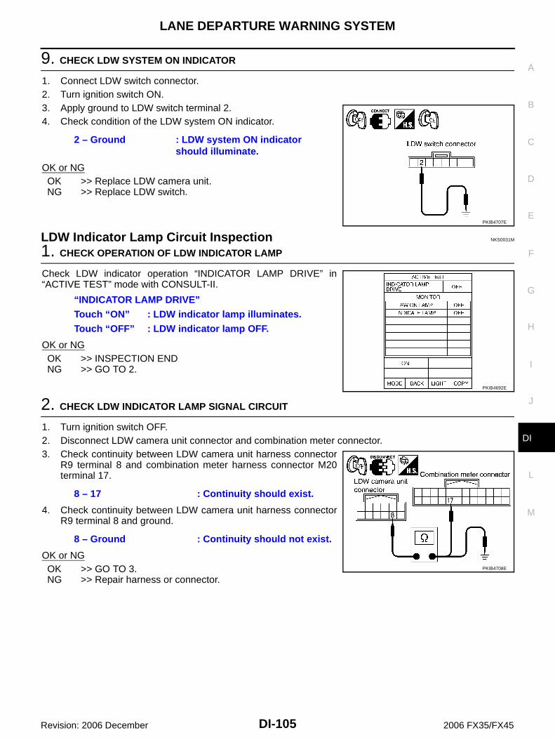
LANE DEPARTURE WARNING SYSTEM
DI-105
C
D
E
F
G
H
I
J
L
M
A
B
DI
Revision: 2006 December 2006 FX35/FX45
9. CHECK LDW SYSTEM ON INDICATOR
1. Connect LDW switch connector.2. Turn ignition switch ON.3. Apply ground to LDW switch terminal 2.4. Check condition of the LDW system ON indicator.
OK or NGOK >> Replace LDW camera unit.NG >> Replace LDW switch.
LDW Indicator Lamp Circuit Inspection NKS0031M
1. CHECK OPERATION OF LDW INDICATOR LAMP
Check LDW indicator operation “INDICATOR LAMP DRIVE” in“ACTIVE TEST” mode with CONSULT-II.
OK or NGOK >> INSPECTION ENDNG >> GO TO 2.
2. CHECK LDW INDICATOR LAMP SIGNAL CIRCUIT
1. Turn ignition switch OFF.2. Disconnect LDW camera unit connector and combination meter connector.3. Check continuity between LDW camera unit harness connector
R9 terminal 8 and combination meter harness connector M20terminal 17.
4. Check continuity between LDW camera unit harness connectorR9 terminal 8 and ground.
OK or NGOK >> GO TO 3.NG >> Repair harness or connector.
2 – Ground : LDW system ON indicator should illuminate.
PKIB4707E
“INDICATOR LAMP DRIVE”Touch “ON” : LDW indicator lamp illuminates.Touch “OFF” : LDW indicator lamp OFF.
PKIB4692E
8 – 17 : Continuity should exist.
8 – Ground : Continuity should not exist.
PKIB4708E

DI-106
LANE DEPARTURE WARNING SYSTEM
Revision: 2006 December 2006 FX35/FX45
3. CHECK LDW INDICATOR LAMP OPERATION
1. Connect combination meter connector.2. Turn ignition switch ON.3. Ground combination meter harness connector M20 terminal 17.
OK or NGOK >> Replace LDW camera unit.NG >> Replace combination meter.
Turn Signal Input Inspection NKS0031N
1. CHECK TURN SIGNAL INPUT
Check turn signal input “TURN SIGNAL” in “DATA MONITOR” modewith CONSULT-II.
OK or NGOK >> INSPECTION ENDNG >> Check turn signal and hazard warning lamps system,
and repair or replace corresponding parts. Refer to LT-102, "How to Proceed With Trouble Diagnosis" .
Electrical Component Inspection NKS003IB
LDW SWITCHCheck continuity between terminals 6 and 7.
17 – Ground : LDW indicator should illuminate.
PKIB4709E
“TURN SIGNAL”When lighting switch is in TURN RH position : RHWhen lighting switch is in TURN LH position : LHWhen hazard switch is turned ON : RH/LH
SKIB3125E
Terminal Condition Continuity
6 7When LDW switch is pressed. Yes
When LDW switch is released. No
PKIB4704E

LANE DEPARTURE WARNING SYSTEM
DI-107
C
D
E
F
G
H
I
J
L
M
A
B
DI
Revision: 2006 December 2006 FX35/FX45
Removal and Installation for LDW Camera Unit NKS0031O
REMOVAL1. Remove roof console. Refer to EI-42, "HEADLINING" .2. Disconnect LDW camera unit connector.3. Remove the bolts (3), and remove LDW camera unit.
INSTALLATIONInstallation is the reverse order of removal.CAUTION: Remove the camera lens cap for replacement. Never give an impact to the LDW camera unit. Adjust the camera aiming every time the LDW camera unit is removed or installed. Refer to DI-83,
"Camera Aiming Adjustment" .
Removal and Installation for LDW Chime NKS0031P
REMOVAL1. Remove instrument side panel (LH). Refer to IP-10, "INSTRU-
MENT PANEL ASSEMBLY" .2. Remove the bolt (1).3. Disconnect LDW chime connector and remove LDW chime.
INSTALLATIONInstallation is the reverse order of removal.
Removal and Installation for LDW Switch NKS0031Q
Refer to IP-10, "INSTRUMENT PANEL ASSEMBLY" .
SKIB1791E
SKIB1802E

DI-108
CAN COMMUNICATION
Revision: 2006 December 2006 FX35/FX45
CAN COMMUNICATION PFP:23710
System Description NKS003HO
CAN (Controller Area Network) is a serial communication line for real time application. It is an on-vehicle mul-tiplex communication line with high data communication speed and excellent error detection ability. Many elec-tronic control units are equipped onto a vehicle, and each control unit shares information and links with othercontrol units during operation (not independent). In CAN communication, control units are connected with 2communication lines (CAN-H line, CAN-L line) allowing a high rate of information transmission with less wiring.Each control unit transmits/receives data but selectively reads required data only.
CAN Communication Unit NKS003HP
Refer to DI-108, "CAN Communication Unit" in “LAN SYSTEM”.

COMPASS
DI-109
C
D
E
F
G
H
I
J
L
M
A
B
DI
Revision: 2006 December 2006 FX35/FX45
COMPASS PFP:24835
Precautions for Compass NKS003HQ
NOTE: Do not install the ski rack, antenna, etc. which is attach to the vehicle with a magnet base. It affects the
operation of the compass. When cleaning the mirror, use a paper towel or similar material dampened with glass cleaner. Do not
spray glass cleaner directly on the mirror as it may cause the liquid cleaner to enter the mirror housing.
System Description NKS003HR
This electronic compass is able to display 8 primary directions:N, NE, E, SE, S, SW, W, NW.
The inside mirror switch (2) is used to operate the compass andautomatic anti-glare system.
Switch Operation
NOTE:For further details of the compass and automatic anti-glare system, refer to Owner's Manual
All standard compasses determine direction relative to Magnetic North; however, this electronic compassis designed to display direction relative to True North.
The difference between Magnetic North and True North varies from place to place across the surface ofthe earth.
This electronic compass must be “told” approximately where it is on the earth’s surface so that the Mag-netic North reading can be properly converted into a True North display.
To tell the electronic compass where it’s at, the earth is separated into numbered “Zone Variances”. TheZone Variance number in which the compass is to function must be entered into this electronic compass.
Each zone is magnetically about 4.2° wide. Typically, anything under 22.5° total zone change is notnoticed on the electronic compass display. However, over 22.5°, a reading may be off by one or more pri-mary directions.
On long trips, a vehicle may leave its original zone and enter one or more new zones. Generally, you donot need to reset the compass zone if you travel between 3 or 4 zones, such as business travel or vaca-tion. The typical driver will not notice any difference on the display within 3 or 4 zones. However, if thevehicle is “permanently” moved to a new location, it is recommended that the compass zone be reset.
SKIB8487E
1. Compass display
2. Inside mirror switch
Press Compass is turned ON/OFF
Press and hold(for 3 – 6 sec.)
Automatic anti-glare system turns ON/OFF
Press and hold(for 6 – 9 sec.)
Compass display turns to zone variation change mode
Press and hold(for more than 9 sec.)
Compass display turns to calibration mode

DI-110
COMPASS
Revision: 2006 December 2006 FX35/FX45
Troubleshooting NKS003HS
The electronic compass is highly protected from changes in most magnetic fields. However, some largechanges in magnetic fields can affect it. Some examples are (but not limited to): high tension power lines,large steel buildings, subways, steel bridges, automatic car washes, large piles of scrap metal, etc. Whilethis does not happen very often, it is possible.
During normal operation, the Compass Mirror will continuously update the compass calibration to adjustfor gradual changes in the vehicle's magnetic “remnant” field. If the vehicle is subjected to high magneticinfluences, the compass may appear to indicate false headings, become locked, or appear that it isunable to be calibrated. If this occurs, perform the calibration procedure.
If at any time the compass continually displays the incorrect direction or the reading is erratic or locked,verify the correct zone variance.
Troubleshooting Chart
Symptom Cause Solution / Reference
The compass display reads “C”.
Compass is not calibrated.
Incorrect zone variance setting.
Large change in magnetic field (Steel bridges, subways, concentrations of metal, carwashes, etc.)
Compass was calibrated incorrectly or in the presence of a strong magnetic field.
Perform Calibration.Refer to DI-111, "Calibration Procedure" .
Compass shows the wrong direction.
Compass does not change direction – appears “Locked”.
Compass does not show all the directions, one or more is missing.
The compass was calibrated but it “loses” calibration.
On long trips the compass shows the wrong direction.
Perform Zone Variation Setting if correct reading is desired in that location.Refer to DI-111, "Zone Variation Setting Procedure" .
Compass does not work – No direction is displayed.
Compass not turned ON.Check for green LED indicator (inside mir-ror switch).
No power to inside mirror. Check power supply circuit.

COMPASS
DI-111
C
D
E
F
G
H
I
J
L
M
A
B
DI
Revision: 2006 December 2006 FX35/FX45
Zone Variation Setting Procedure NKS003HT
NOTE:The zone setting is factory preset (“default” setting) to zone 8.1. Press and hold the inside mirror switch for 6 – 9 seconds.2. The current zone setting appears on the compass display.3. Find the current geographical location number in the Zone Varia-
tion Chart.4. Select the new zone number. (Press the inside mirror switch
until the new zone number appears on the compass display.)5. After select the new zone number, the compass display will
automatically shows a direction within a few seconds.6. Preform the following Calibration Procedure for more accurate
indications.
Calibration Procedure NKS003HU
NOTE:The compass calibrates itself under normal driving conditions. However, occasional circumstances may causethe compass to operate inaccurately. Example: Driving from rural (wide open) areas to crowded city areas, orif an aftermarket (i.e., non original equipment) antenna with a magnetic base is attached to the vehicle. Cali-brate the mirror compass if the display shows only one direction or a limited number of directions.NOTE: If “magnetic hats” are used in the dealership for vehicle identification, remove the hat from the vehicle
before performing the following steps. Do NOT put the hat back on the vehicle after the procedure is com-pleted.
Drive the vehicle to an open level area; away from large metallic objects, structures, and overhead powerlines.
Turn off “non-essential” electrical accessories (rear window defrost, heater/air conditioning, wipers) andclose the doors.
1. Verify the correct compass zone setting for the geographical location. Refer to DI-111, "Zone VariationSetting Procedure" .
2. Press and hold the inside mirror switch for more than 9 seconds.3. “C” is displayed on the compass display, when calibration starts.4. Drive slowly [less than 8 km/h (5 mph)] in a circle until the “C / CAL” is replaced with primary headings (N,
NE, E, SE, S, SW, W, or NW).NOTE:This will require driving at least 2 complete 360 degree circles; 3 complete circles may be required.
5. The compass calibration procedure is now complete. The compass should operate normally.NOTE:If at any time the compass continually displays the incorrect direction or the reading is erratic or locked,repeat the calibration procedure.
SEL168Y

DI-112
COMPASS
Revision: 2006 December 2006 FX35/FX45
Wiring Diagram — COMPAS — NKS003HV
TKWM4344E

COMPASS
DI-113
C
D
E
F
G
H
I
J
L
M
A
B
DI
Revision: 2006 December 2006 FX35/FX45
Removal and Installation of Compass NKS003HW
Refer to GW-66, "Removal and Installation" .

DI-114
CLOCK
Revision: 2006 December 2006 FX35/FX45
CLOCK PFP:25820
Wiring Diagram — CLOCK — NKS0031R
TKWM4360E

CLOCK
DI-115
C
D
E
F
G
H
I
J
L
M
A
B
DI
Revision: 2006 December 2006 FX35/FX45
Removal and Installation of Clock NKS0031S
REMOVAL1. Remove A/T selecter lever knob. Refer to IP-12, "(D) A/T Select Lever Knob" .2. Remove A/T console finisher. Refer to IP-12, "(F) A/T Console Finisher" .3. Remove instrument clock finisher. Refer to IP-12, "(E) Instrument Clock Finisher" .4. Remove tabs (A), and remove clock (1) from instrument clock
finisher (2).
INSTALLATIONInstallation is the reverse order of removal.
SKIB8488E

DI-116
REAR VIEW MONITOR
Revision: 2006 December 2006 FX35/FX45
REAR VIEW MONITOR PFP:28260
System Description NKS0031T
The rear view monitor is equipped to check the rearward of the vehicle with display when A/T selectorlever is in reverse position.
The lines of vehicle sides and the distance from the rear end of the vehicle are provided on display as aguide. It allows the driver to know the distance between the vehicle and a rearward object, and the widthof the vehicle much easier.
POWER SUPPLY AND GROUNDPower is supplied at all time through 10A fuse [No. 19, located in fuse block (J/B)] to rear view camera control unit terminal 1.When ignition switch is in ACC or ON position, power is supplied through 10A fuse [No. 6, located in fuse block (J/B)] to rear view camera control unit terminal 2.When ignition switch is in ON or START position, power is supplied through 10A fuse (No. 83, located in IPDM E/R) to back-up lamp relay terminals 1 and 3.Ground is supplied to rear view camera control unit terminal 3 through grounds M35, M45 and M85.
AV COMMUNICATION LINERear view camera control unit is connected to the following units with AV communication line. Each unit trans-mits/receives data with AV communication line. NAVI control unit Display Display control unit A/C and AV switch
REAR VIEW CAMERA OPERATIONWhen A/T selector lever is reverse position, power is supplied through back-up lamp relay terminal 2 to TCM terminal 7.Then back-up lamp relay is energized, from back-up lamp relay terminal 5 to rear view camera control unit terminal 4.Then, rear view camera control unit is sent camera ON signal through rear view camera control unit terminal 8 to rear view camera terminal 1.An image taken by rear view camera is sent through rear view camera terminals 3 and 4 to rear view camera control unit terminals 10 and 9. Then an image is sent through rear view camera control unit terminals 12 and 14 to the display terminals 15 and 16.An image of rear view will be projected on the display.

REAR VIEW MONITOR
DI-117
C
D
E
F
G
H
I
J
L
M
A
B
DI
Revision: 2006 December 2006 FX35/FX45
Side Distance GuidelineWhen A/T selector lever is in reverse position, rear view camera control unit is sent rear view camera guidelineimage through rear view camera control unit terminals 12 and 14 to the display terminals 15 and 16.Rear view camera guideline will be projected on the display.Display shows image from rear view camera image and rear view camera guideline.
Component Parts and Harness Connector Location NKS0031U
SKIB8489E

DI-118
REAR VIEW MONITOR
Revision: 2006 December 2006 FX35/FX45
Schematic NKS0031V
TKWM4361E
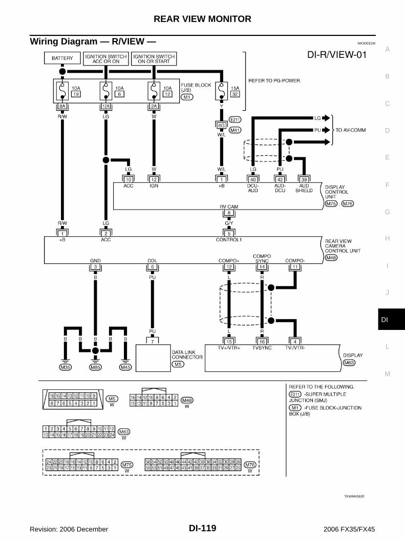
REAR VIEW MONITOR
DI-119
C
D
E
F
G
H
I
J
L
M
A
B
DI
Revision: 2006 December 2006 FX35/FX45
Wiring Diagram — R/VIEW — NKS0031W
TKWM4362E

DI-120
REAR VIEW MONITOR
Revision: 2006 December 2006 FX35/FX45
TKWM4363E

REAR VIEW MONITOR
DI-121
C
D
E
F
G
H
I
J
L
M
A
B
DI
Revision: 2006 December 2006 FX35/FX45
TKWM4364E

DI-122
REAR VIEW MONITOR
Revision: 2006 December 2006 FX35/FX45
Terminals and Reference Value for Rear View Camera Control Unit NKS0031X
Terminals
Item
Condition
Reference valueTerminal No.
Wire color
Ignition switch
Operation
1 R/W Battery power supply OFF — Battery voltage
2 LG Ignition power supply ACC — Battery voltage
3 B Ground ON — Approx. 0 V
4 OR Reverse signal input ON
A/T selector lever R range position
Battery voltage
A/T selector lever in other than R range position
Approx. 0 V
5 G/Y CONTROL 1 ON — Approx. 0 V
6 PU DDL — — —
8 R/W Camera power output ONA/T selector lever R range position
Approx. 6 V
9 — Camera image input (–) ON — Approx. 0 V
10 W Camera image input (+) ONA/T selector lever R range position
11 — Shield ground — — —
12 L Composite image output ONA/T selector lever R range position
14 RComposite image synchroni-zation signal output
ONA/T selector lever R range position
SKIA4894E
SKIA4896E
SKIA5896E

REAR VIEW MONITOR
DI-123
C
D
E
F
G
H
I
J
L
M
A
B
DI
Revision: 2006 December 2006 FX35/FX45
CONSULT-II Function (REARVIEW CAMERA) NKS0031Y
CONSULT-II can display each diagnostic item using the diagnostic test modes shown following.
CONSULT-II BASIC OPERATIONRefer to GI-38, "CONSULT-II Start Procedure" .
WORK SUPPORTOperation Procedure1. Touch “DATA MONITOR” on “SELECT DIAG MODE” screen.2. Touch either “SELCT GUIDELINE PATTERN” or “ADJ GUIDELINE POSITION” on the “WORK SUP-
PORT” screen.
Refer to DI-124, "SIDE DISTANCE GUIDELINE CORRECTION PROCEDURE" for detail.
DATA MONITOROperation Procedure1. Touch “DATA MONITOR” on “SELECT DIAG MODE” screen.2. Touch either “ALL SIGNALS” or “SELECTION FROM MENU” on the “DATA MONITOR” screen.
3. When “SELECTION FROM MENU” is selected, touch individual items to be monitored. When “ALL SIG-NALS” is selected, all items will be monitored.
4. Touch “START”.5. Touch “RECORD” while monitoring, then the status of the monitored item can be recorded. To stop
recording, touch “STOP”.
Display Item List
System Diagnosis mode DescriptionReference
page
REARVIEW CAMERA
WORK SUPPORTIt can adjust the side distance guidelines which overlap the rear view monitor image.
DI-123
DATA MONITORDisplays rear view camera control unit input data in real time.
DI-123
ECU PART NUMBER Displays part number of rear view camera control unit. —
SELCT GUIDELINE PATTERN Side distance guideline is optional from two patterns.
ADJ GUIDELINE POSITION Side distance guideline is adjustable toward up and down, right and left.
ALL SIGNALS Monitors all signals.
SELECTION FROM MENU Selects and monitors individual signal.
Display item [Unit]ALL
SIGNALSSELECTION FROM MENU
Contents
R POSI SIG [ON/OFF] X X Indicates [ON/OFF] condition of R range position signal input.

DI-124
REAR VIEW MONITOR
Revision: 2006 December 2006 FX35/FX45
Side Distance Guideline Correction NKS0031Z
This mode is used to modify the side distance guidelines if they are dislocated from the rear view monitorimage, because of variations of body/camera mounting conditions.
SIDE DISTANCE GUIDELINE CORRECTION PROCEDURE1. Create a correction line to modify the screen.
Draw lines on the rearward of the vehicle passing through thefollowing points: 0.2 m (7.87 in) from both sides of the vehicle,and *1: 0.5 m (1.64 feet) *2: 1 m (3.28 feet) *3: 2 m (6.56 feet) *4: 3 m (9.84 feet)
and from the rear end of the bumper2. With the ignition switch OFF, connect “CONSULT-II” and “CON-
SULT-II CONVERTER” to the data link connector, then turn igni-tion switch ON. Touch “REARVIEW CAMERA” on CONSULT-II.CAUTION:Stop engine for the safety when correcting side distanceguideline.
3. Shift A/T selector lever to R position.
4. Touch “SELCT GUIDELINE PATTERN” on “SELECT WORKITEM” screen.
SKIA5637E
SKIA6103E
SKIA5638E

REAR VIEW MONITOR
DI-125
C
D
E
F
G
H
I
J
L
M
A
B
DI
Revision: 2006 December 2006 FX35/FX45
5. Touch “UP” or “DOWN”, and select the guide line, “PATTERNNO. 0” or “PATTERN NO. 1”, which is the closest to the cor-rected line.
6. Touch “SAVE”, and confirm the guide line.7. Touch “END”.
8. Touch “ADJ GUIDELINE POSITION” on “SELECT WORKITEM” screen.
9. Adjust the guide line touching “X UP”, “X DOWN”, “Y UP” or “YDOWN” so that the corrected line can fit the guide line.
10. Touch “SAVE”, and confirm the guide line.11. Touch “END” to finish correcting.
PKIB2264E
SKIA5638E
PKIB2265E

DI-126
REAR VIEW MONITOR
Revision: 2006 December 2006 FX35/FX45
Power Supply and Ground Circuit Inspection NKS00320
1. CHECK FUSE
Make sure the fuses for rear view camera control unit is blown.
OK or NGOK >> GO TO 2.NG >> Be sure to eliminate cause of malfunction before installing new fuse. Refer to PG-3, "POWER
SUPPLY ROUTING CIRCUIT" .
2. CHECK POWER SUPPLY CIRCUIT
Check voltage between rear view camera control unit harness con-nector M48 terminals 1, 2 and ground.
OK or NGOK >> GO TO 3.NG >> Check harness between rear view camera control unit and fuse.
3. CHECK REAR VIEW CAMERA CONTROL UNIT GROUND CIRCUIT
1. Turn ignition switch OFF.2. Disconnect rear view camera control unit connector. 3. Check continuity between rear view camera control unit harness
connector M48 terminal 3 and ground.
OK or NGOK >> INSPECTION ENDNG >> Repair harness or connector.
Power source Fuse No.
Battery power supply 19
ACC power supply 6
Terminals
OFF ACC(+)(–)
Connector Terminal
M481 Ground Battery voltage Battery voltage
2 Ground 0 V Battery voltage
PKIB3580E
3 – Ground : Continuity should exist.
SKIA5081E

REAR VIEW MONITOR
DI-127
C
D
E
F
G
H
I
J
L
M
A
B
DI
Revision: 2006 December 2006 FX35/FX45
Rear View Is Not Displayed With The A/T Selector Lever In R-Position NKS00321
1. BACK-UP LAMP INSPECTION
1. Turn ignition switch ON.2. Shift A/T selector lever to R position.Does back-up lamp illuminate?YES >> GO TO 2.NO >> Check back-up lamp system. Refer to LT-131, "BACK-UP LAMP" in LT section.
2. CHECK REVERSE POSITION INPUT SIGNAL
With CONSULT-II1. Select “DATA MONITOR” of “REARVIEW CAMERA”.2. Operate ignition switch with “R POSI SIG” of “DATA MONITOR”
and check operate status.
Without CONSULT-II1. Turn ignition switch OFF.2. Disconnect rear view camera control unit connector.3. Turn ignition switch ON.4. Shift A/T selector lever to R position.5. Check voltage between rear view camera control unit harness
connector M48 terminal 4 and ground.
OK or NGOK >> GO TO 3.NG >> Check harness between rear view camera control unit
and back-up lamp relay.
SKIA7147E
4 – Ground : Battery voltage
SKIA5086E

DI-128
REAR VIEW MONITOR
Revision: 2006 December 2006 FX35/FX45
3. CHECK DISPLAY CONTROL UNIT OUTPUT SIGNAL
1. Turn ignition switch OFF.2. Disconnect rear view camera control unit connector.3. Turn ignition switch ON.4. Check voltage between rear view camera control unit harness
connector M48 terminal 5 and ground.
OK or NGOK >> GO TO 5.NG >> GO TO 4.
4. CHECK DISPLAY CONTROL UNIT CIRCUIT
1. Turn ignition switch OFF.2. Disconnect display control unit connector.3. Check continuity between rear view camera control unit harness
connector M48 terminal 5 and display control unit harness con-nector M75 terminal 8.
4. Check continuity between rear view camera control unit harnessconnector M48 terminal 5 and ground.
OK or NGOK >> Replace display control unit.NG >> Repair harness or connector.
5. CHECK CONTROL 1 SIGNAL
1. Turn ignition switch OFF.2. Connect rear view camera control unit connector.3. Turn ignition switch ON.4. Shift A/T selector lever to R position.5. Check voltage between rear view camera control unit harness
connector M48 terminal 5 and ground.
OK or NGOK >> GO TO 6.NG >> Replace rear view camera control unit.
5 – Ground : Approx. 5 V
SKIA7148E
5 – 8 : Continuity should exist.
5 – Ground : Continuity should not exist.
SKIA7149E
5 – Ground : Approx. 0 V
SKIA7150E

REAR VIEW MONITOR
DI-129
C
D
E
F
G
H
I
J
L
M
A
B
DI
Revision: 2006 December 2006 FX35/FX45
6. CHECK REAR VIEW CAMERA OPEN CIRCUIT
1. Turn ignition switch OFF.2. Disconnect rear view camera connector.3. Check continuity between rear view camera control unit harness
connector M48 terminal 8 and rear view camera harness con-nector D108 terminal 1.
4. Check continuity between rear view camera control unit harnessconnector M48 terminal 9 and rear view camera harness con-nector D108 terminal 4.
5. Check continuity between rear view camera control unit harnessconnector M48 terminal 10 and rear view camera harness con-nector D108 terminal 3.
OK or NGOK >> GO TO 7.NG >> Repair harness or connector.
7. CHECK REAR VIEW CAMERA SHORT CIRCUIT
1. Check continuity between rear view camera control unit harnessconnector M48 terminal 8 and ground.
2. Check continuity between rear view camera control unit harnessconnector M48 terminal 9 and ground.
3. Check continuity between rear view camera control unit harnessconnector M48 terminal 10 and ground.
OK or NGOK >> GO TO 8.NG >> Repair harness on connector.
8. CHECK POWER SUPPLY AND GROUND CIRCUIT
Check power supply and ground circuit. Refer to DI-126, "Power Supply and Ground Circuit Inspection" .OK or NGOK >> GO TO 9.NG >> Repair or replace power supply and ground circuit.
8 – 1 : Continuity should exist.
9 – 4 : Continuity should exist.
10 – 3 : Continuity should exist.
SKIA5095E
8 – Ground : Continuity should not exist.
9 – Ground : Continuity should not exist.
10 – Ground : Continuity should not exist.SKIA5098E

DI-130
REAR VIEW MONITOR
Revision: 2006 December 2006 FX35/FX45
9. CHECK REAR VIEW CAMERA CONTROL UNIT OUTPUT SIGNAL
1. Turn ignition switch OFF.2. Connect rear view camera control unit connector.3. Turn ignition switch ON.4. Shift A/T selector lever to R position.5. Check voltage between rear view camera control unit harness
connector M48 terminal 8 and ground.
OK or NGOK >> GO TO 10.NG >> Replace rear view camera control unit.
10. CHECK REAR VIEW CAMERA SIGNAL
1. Turn ignition switch OFF.2. Connect rear view camera connector.3. Turn ignition switch ON.4. Shift A/T selector lever to R position.5. Check voltage signal between rear view camera control unit har-
ness connector M48 terminal 10 and ground.
OK or NGOK >> GO TO 11.NG >> Replace rear view camera.
11. CHECK COMPOSITE SIGNAL CIRCUIT
1. Turn ignition switch OFF.2. Disconnect rear view camera control unit connector and display connector.3. Check continuity between rear view camera control unit harness
connector M48 terminal 12 and display harness connector M63terminal 15.
4. Check continuity between rear view camera control unit harnessconnector M48 terminal 12 and ground.
OK or NGOK >> GO TO 12.NG >> Repair harness or connector.
8 – Ground : Approx. 6 V
PKIB3581E
10 – Ground:
PKIB3582E
SKIA4894E
12 – 15 : Continuity should exist.
12 – Ground : Continuity should not exist.
SKIB0482E

REAR VIEW MONITOR
DI-131
C
D
E
F
G
H
I
J
L
M
A
B
DI
Revision: 2006 December 2006 FX35/FX45
12. CHECK COMPOSITE SIGNAL GROUND CIRCUIT
1. Check continuity between rear view camera control unit harnessconnector M48 terminal 11 and display harness connector M63terminal 4.
2. Check continuity between rear view camera control unit harnessconnector M48 terminal 11 and ground.
OK or NGOK >> GO TO 13.NG >> Repair harness or connector.
13. CHECK COMPOSITE SIGNAL
1. Connect rear view camera control unit connector and display connector.2. Turn ignition switch ON.3. Shift A/T selector lever to R position.4. Check voltage signal between rear view camera control unit har-
ness connector M48 terminal 12 and ground.
OK or NGOK >> Replace display.NG >> Replace rear view camera control unit.
The Rear View Image Is Distorted NKS00322
1. CHECK SYNCHRO SIGNAL OPEN OR SHORT CIRCUIT
1. Turn ignition switch OFF.2. Disconnect rear view camera control unit connector and display connector.3. Check continuity between rear view camera control unit harness
connector M48 terminal 14 and display harness connector M63terminal 16.
4. Check continuity between rear view camera control unit harnessconnector M48 terminal 14 and ground.
OK or NGOK >> GO TO 2.NG >> Repair harness or connector.
11 – 4 : Continuity should exist.
11 – Ground : Continuity should not exist.
SKIA5102E
12 – Ground:
PKIB3583E
SKIA4896E
14 – 16 : Continuity should exist.
14 – Ground : Continuity should not exist.
SKIA5101E

DI-132
REAR VIEW MONITOR
Revision: 2006 December 2006 FX35/FX45
2. CHECK COMPOSITE SIGNAL GROUND CIRCUIT
1. Check continuity between rear view camera control unit harnessconnector M48 terminal 11 and display harness connector M63terminal 4.
2. Check continuity between rear view camera control unit harnessconnector M48 terminal 11 and ground.
OK or NGOK >> GO TO 3.NG >> Repair harness or connector.
3. CHECK REAR VIEW CONTROL UNIT SYNCHRO SIGNAL
1. Connect rear view camera control unit connector and display connector.2. Turn ignition switch ON.3. Shift A/T selector lever to R position.4. Check voltage signal between rear view camera control unit har-
ness connector M48 terminal 14 and ground.
OK or NGOK >> Replace rear view camera control unit.NG >> Replace display.
Removal and Installation of Rear View Camera Control Unit NKS00323
REMOVAL1. Remove instrument clock finisher and A/T console finisher.
Refer to IP-10, "INSTRUMENT PANEL ASSEMBLY" .2. Remove screws (2), and remove rear view camera control unit.
INSTALLATIONInstallation is the reverse order of removal.
11 – 4 : Continuity should exist.
11 – Ground : Continuity should not exist.
SKIA5102E
14 – Ground:
PKIB3584E
SKIA5896E
SKIA5797E

REAR VIEW MONITOR
DI-133
C
D
E
F
G
H
I
J
L
M
A
B
DI
Revision: 2006 December 2006 FX35/FX45
Removal and Installation of Rear View Camera NKS00324
REMOVAL1. Remove back door trim. Refer to EI-46, "BACK DOOR TRIM" .2. Remove back door outside finisher upper. Refer to EI-46, "BACK DOOR OUTSIDE FINISHER"3. Remove licence lamp bolts (A).
4. Disconnect rear wiper connector.5. Disconnect rear view camera connector (1) and back door
opener switch connector (2).6. Cut off back door module along the line (A).7. Remove back door opener switch and rear view camera assem-
bly (3). Rear wiper (4)
8. Remove screws (A), and remove rear view camera (1) fromback door opener switch (2).
INSTALLATIONInstallation is the reverse order of removal.
SKIB8490E
SKIB8491E
SKIB8492E

DI-134
REAR VIEW MONITOR
Revision: 2006 December 2006 FX35/FX45