Embed Size (px)
Citation preview
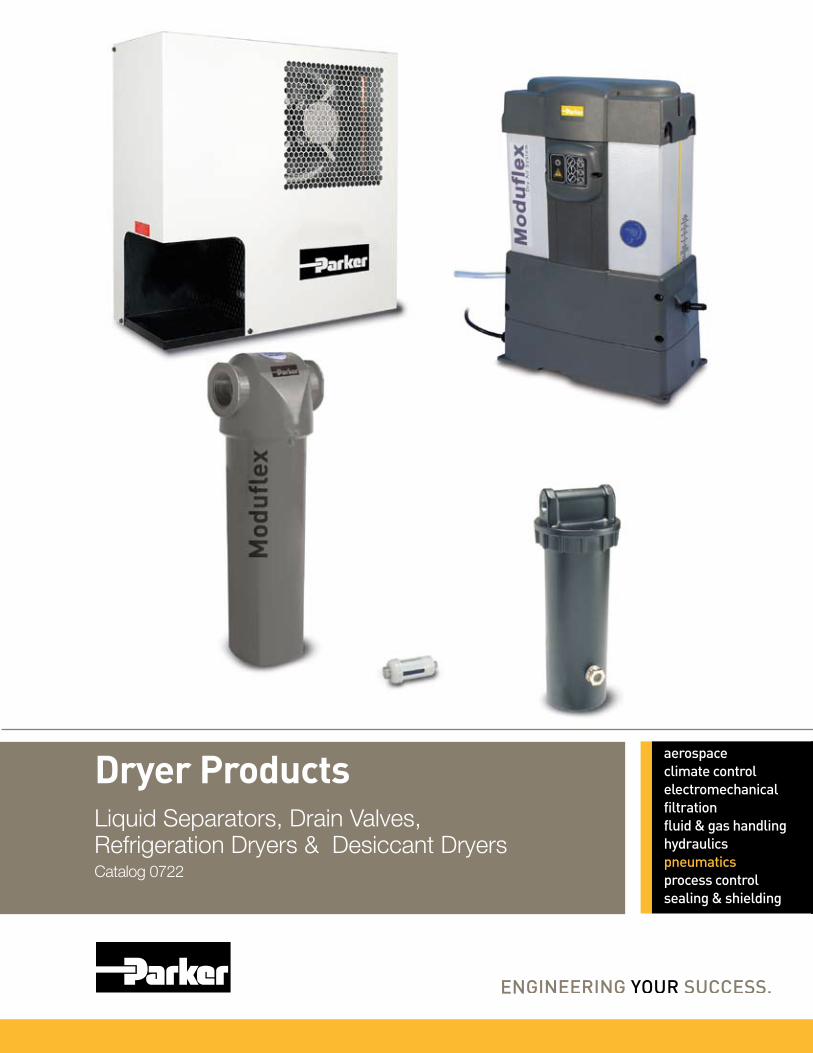
Dryer Products
Liquid Separators, Drain Valves, Refrigeration Dryers & Desiccant DryersCatalog 0722

WARNINGFAILURE OR IMPROPER SELECTION OR IMPROPER USE OF THE PRODUCTS AND/OR SYSTEMS DESCRIBED HEREIN OR RELATED ITEMS CAN CAUSE DEATH, PERSONAL INJURY AND PROPERTY DAMAGE.This document and other information from Parker Hannifin Corporation, its subsidiaries and authorized distributors provide product and/or system options for further investigation by users having technical expertise. It is important that you analyze all aspects of your application including consequences of any failure, and review the information concerning the product or system in the current product catalog. Due to the variety of operating conditions and applications for these products or systems, the user, through its own analysis and testing, is solely responsible for making the final selection of the products and systems and assuring that all performance, safety and warning requirements of the application are met.The products described herein, including without limitation, product features, specifications, designs, availability and pricing, are subject to change by Parker Hannifin Corporation and its subsidiaries at any time without notice.
Offer of SaleThe items described in this document are hereby offered for sale by Parker Hannifin Corporation, its subsidiaries or its authorized distributors. This offer and its acceptance are governed by the provisions stated on the separate page of this document entitled “Offer of Sale”.
© Copyright 2008 Parker Hannifin Corporation. All Rights Reserved
!
Air Preparation SystemsCatalog 0722
Warning, Offer of Sale
Parker Hannifin CorporationPneumatic DivisionRichland, Michiganwww.parker.com/pneumatics
CAUTION:Polycarbonate bowls, being transparent and tough, are ideal for use with Filters and Lubricators. They are suitable for use in normal industrial environments, but should not be located in areas where they could be subjected to direct sunlight, an impact blow, nor temperatures outside of the rated range. As with most plastics, some chemicals can cause damage. Polycarbonate bowls should not be exposed to chlorinated hydro-carbons, ketones, esters and certain alcohols. They should not be used in air systems where compressors are lubricated with fire-resistant fluids such as phosphate ester and di-ester types.
Metal bowls are recommended where ambient and/or media conditions are not compatible with polycarbonate bowls. Metal bowls resist the action of most such solvents, but should not be used where strong acids or bases are present or in salt laden atmospheres. Consult the factory for specific recommendations where these conditions exist.
TO CLEAN POLYCARBONATE BOWLS USE MILD SOAP AND WATER ONLY! DO NOT use cleansing agents such as acetone, benzene, carbon tetrachloride, gasoline, toluene, etc., which are damaging to this plastic.
Metal bowl guards are recommended for all applications.
!

Parker Hannifin CorporationPneumatic DivisionRichland, Michiganwww.parker.com/pneumatics
1
Air Preparation SystemsCatalog 0722
Table of Contents
Sources of Contamination ....................................................................................................... 2-4
Purification Technologies .............................................................................................................5
Quality Standards ........................................................................................................................6
Purity Levels ................................................................................................................................7
P3TF Liquid Separators ......................................................................................................... 8-11
Automatic Electrical Drain Valve – WDV3-G ..............................................................................12
Zero Loss Drain – WDV2 ...........................................................................................................13
PDRD Refrigeration Dryers ................................................................................................. 14-18
Mini Disposable Inline Desiccant Dryer .....................................................................................19
DD Series Inline Desiccant Dryers ...................................................................................... 20-21
Regenerative Desiccant Dryers – P3TJA ............................................................................ 22-29
Safety Guide ........................................................................................................................ 30-31
Offer of Sale ..............................................................................................................................32
Together, we can separate the good from the bad.
Parker Hannifin CorporationPneumatic DivisionRichland, Michiganwww.parker.com/pneumatics
2
Air Preparation SystemsCatalog 0722
Sources of Contamination
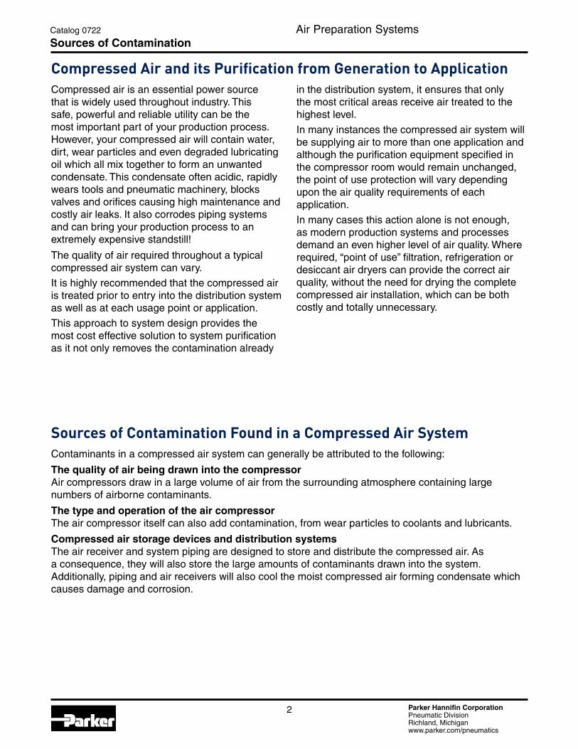
Compressed air is an essential power source that is widely used throughout industry. This safe, powerful and reliable utility can be the most important part of your production process. However, your compressed air will contain water, dirt, wear particles and even degraded lubricating oil which all mix together to form an unwanted condensate. This condensate often acidic, rapidly wears tools and pneumatic machinery, blocks valves and orifices causing high maintenance and costly air leaks. It also corrodes piping systems and can bring your production process to an extremely expensive standstill!
The quality of air required throughout a typical compressed air system can vary.
It is highly recommended that the compressed air is treated prior to entry into the distribution system as well as at each usage point or application.
This approach to system design provides the most cost effective solution to system purification as it not only removes the contamination already
in the distribution system, it ensures that only the most critical areas receive air treated to the highest level.
In many instances the compressed air system will be supplying air to more than one application and although the purification equipment specified in the compressor room would remain unchanged, the point of use protection will vary depending upon the air quality requirements of each application.
In many cases this action alone is not enough, as modern production systems and processes demand an even higher level of air quality. Where required, “point of use” filtration, refrigeration or desiccant air dryers can provide the correct air quality, without the need for drying the complete compressed air installation, which can be both costly and totally unnecessary.
Sources of Contamination Found in a Compressed Air SystemContaminants in a compressed air system can generally be attributed to the following:
The quality of air being drawn into the compressor Air compressors draw in a large volume of air from the surrounding atmosphere containing large numbers of airborne contaminants.
The type and operation of the air compressor The air compressor itself can also add contamination, from wear particles to coolants and lubricants.
Compressed air storage devices and distribution systems The air receiver and system piping are designed to store and distribute the compressed air. As a consequence, they will also store the large amounts of contaminants drawn into the system. Additionally, piping and air receivers will also cool the moist compressed air forming condensate which causes damage and corrosion.
Compressed Air and its Purification from Generation to Application

Parker Hannifin CorporationPneumatic DivisionRichland, Michiganwww.parker.com/pneumatics
3
Air Preparation SystemsCatalog 0722
Sources of Contamination
Types of Contamination Found in a Compressed Air SystemAtmospheric Dirt Atmospheric air in an industrial environment typically contains 140 million dirt particles for every cubic meter of air. 80% of these particles are less than 2 microns in size and are too small to be captured by the compressor intake filter, therefore passing directly into the compressed air system.
Water Vapor, Condensed Water and Water Aerosols Atmospheric air contains water vapor (water in a gaseous form). The ability of compressed air to hold water vapor is dependent upon it's temperature. The higher the temperature, the more water vapor that can be held by the air. During compression, the air temperature is increased significantly, which allows it to easily retain the incoming moisture. After the compression stage, air is normally cooled to a usable temperature. This reduces the airs ability to retain water vapor, resulting in a proportion of the water vapor being condensed into liquid water which is removed by a condensate drain fitted to the compressor after-cooler. The air leaving the after-cooler is now 100% saturated with water vapor and any further cooling of the air will result in more water vapor condensing into liquid water. Condensation occurs at various stages throughout the system as the air is cooled further by the air receiver, piping and the expansion of valves, cylinders, tools and machinery. The condensed water and water aerosols cause corrosion to the storage and distribution system, damage production equipment and the end product. It also reduces production efficiency and increases maintenance costs. Water in any form must be removed to enable the system to run correctly and efficiently.
Rust and Pipescale Rust and pipescale can be found in air receivers and the piping of “wet systems” (systems without adequate purification equipment) or systems which were operated “wet” prior to purification being installed. Over time, this contamination breaks away to cause damage or blockage in production which can also contaminate final product and processes.
Micro-organisms Bacteria and viruses will also be drawn into the compressed air system through the compressor intake and warm, moist air provides an ideal environment for the growth of micro-organisms. Ambient air can typically contain up to 3,850 micro-organisms per cubic meter. If only a few micro-organisms were to enter a clean environment, a sterile process or production system, enormous damage could be caused that not only diminishes product quality, but may even render a product entirely unfit for use and subject to recall.
Liquid Oil and Oil Aerosols Most air compressors use oil in the compression stage for sealing, lubrication and cooling. During operation, lubricating oil is carried over into the compressed air system as liquid oil and aerosols. This oil mixes with water vapor in the air and is often very acidic, causing damage to the compressed air storage and distribution system, production equipment and final product.
Oil Vapor In addition to dirt and water vapor, atmospheric air also contains oil in the form of unburned hydrocarbons. The unburned hydrocarbons drawn into the compressor intake as well as vaporized oil from the compression stage of a lubricated compressor will carry over into a compressed air system where it can cool and condense, causing the same contamination issues as liquid oil. Typical oil vapor concentrations can vary between 0.05 and 0.5mg per cubic meter of air.
Parker Hannifin CorporationPneumatic DivisionRichland, Michiganwww.parker.com/pneumatics
4
Air Preparation SystemsCatalog 0722
Sources of Contamination
Contamination and Types of CompressorIt is often believed that the level of compressed air purification equipment required in a system is dependent upon the type of compressor used. Contamination in a compressed air system originates from many sources and is not related solely to the compressor or it's lubricants. No matter what compressor type is selected, adequate filtration and separation products will be required to remove the large volume of dirty contaminated water as well as the dirt, rust, pipescale and microbiological contamination in the system.
Preventative Maintenance Provides You With The Following Benefits:n Lowest Operating Costs
n Superior Compressed Air Quality
n Continued Protection Of Downstream Equipment and Processes
n Peace Of Mind
UP To 99% oF The ToTAl liqUid ConTAMinATion FoUnd in A CoMPreSSed Air SYSTeM iS WATer.Oil is perceived to cause the most problems as it is seen emanating from open drain points and exhausting valves, however, in the majority of instances, it is actually oily condensate (oil mixed with water) that is being observed.
how Much Water Can Be Found in A Typical Compressed Air System?The amount of water in a compressed air system is staggering. A small 100 cfm (2.8m3/min) compressor and refrigeration dryer combination, operating for 4,000 hours in typical climatic conditions can produce approximately 10,000 liters or 2,200 gallons of liquid condensate per year.
If the compressor is oil lubricated with a typical 2ppm (2 mg/m3) oil carryover, then although the resulting condensate would visually resemble oil, oil would in fact account for less than 0.1% of the overall volume and it is this resemblance to oil to which a false association is made.
The example above assumes uses a small compressor to highlight the large volume of condensate produced. If a compressed air system was operated in warmer, more humid climates, or with larger compressors installed, running for longer periods, the volume of condensate would increase significantly.
Parker Hannifin CorporationPneumatic DivisionRichland, Michiganwww.parker.com/pneumatics
5
Air Preparation SystemsCatalog 0722
Purification Technologies
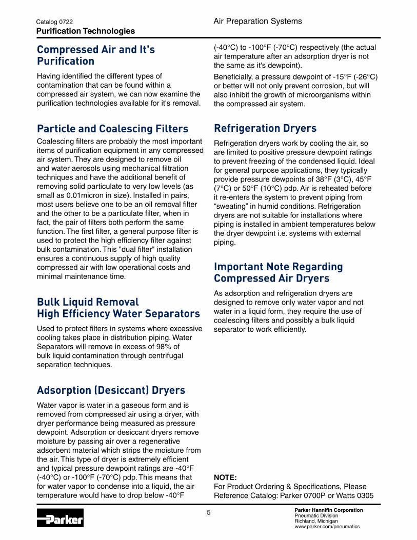
Compressed Air and it's PurificationHaving identified the different types of contamination that can be found within a compressed air system, we can now examine the purification technologies available for it's removal.
Particle and Coalescing FiltersCoalescing filters are probably the most important items of purification equipment in any compressed air system. They are designed to remove oil and water aerosols using mechanical filtration techniques and have the additional benefit of removing solid particulate to very low levels (as small as 0.01micron in size). Installed in pairs, most users believe one to be an oil removal filter and the other to be a particulate filter, when in fact, the pair of filters both perform the same function. The first filter, a general purpose filter is used to protect the high efficiency filter against bulk contamination. This "dual filter" installation ensures a continuous supply of high quality compressed air with low operational costs and minimal maintenance time.
Bulk liquid removal high efficiency Water SeparatorsUsed to protect filters in systems where excessive cooling takes place in distribution piping. Water Separators will remove in excess of 98% of bulk liquid contamination through centrifugal separation techniques.
Adsorption (desiccant) dryersWater vapor is water in a gaseous form and is removed from compressed air using a dryer, with dryer performance being measured as pressure dewpoint. Adsorption or desiccant dryers remove moisture by passing air over a regenerative adsorbent material which strips the moisture from the air. This type of dryer is extremely efficient and typical pressure dewpoint ratings are -40°F (-40°C) or -100°F (-70°C) pdp. This means that for water vapor to condense into a liquid, the air temperature would have to drop below -40°F
NOTE:For Product Ordering & Specifications, Please Reference Catalog: Parker 0700P or Watts 0305
(-40°C) to -100°F (-70°C) respectively (the actual air temperature after an adsorption dryer is not the same as it's dewpoint).
Beneficially, a pressure dewpoint of -15°F (-26°C) or better will not only prevent corrosion, but will also inhibit the growth of microorganisms within the compressed air system.
refrigeration dryersRefrigeration dryers work by cooling the air, so are limited to positive pressure dewpoint ratings to prevent freezing of the condensed liquid. Ideal for general purpose applications, they typically provide pressure dewpoints of 38°F (3°C), 45°F (7°C) or 50°F (10°C) pdp. Air is reheated before it re-enters the system to prevent piping from “sweating” in humid conditions. Refrigeration dryers are not suitable for installations where piping is installed in ambient temperatures below the dryer dewpoint i.e. systems with external piping.
important note regarding Compressed Air dryersAs adsorption and refrigeration dryers are designed to remove only water vapor and not water in a liquid form, they require the use of coalescing filters and possibly a bulk liquid separator to work efficiently.
Parker Hannifin CorporationPneumatic DivisionRichland, Michiganwww.parker.com/pneumatics
6
Air Preparation SystemsCatalog 0722
Quality Standards
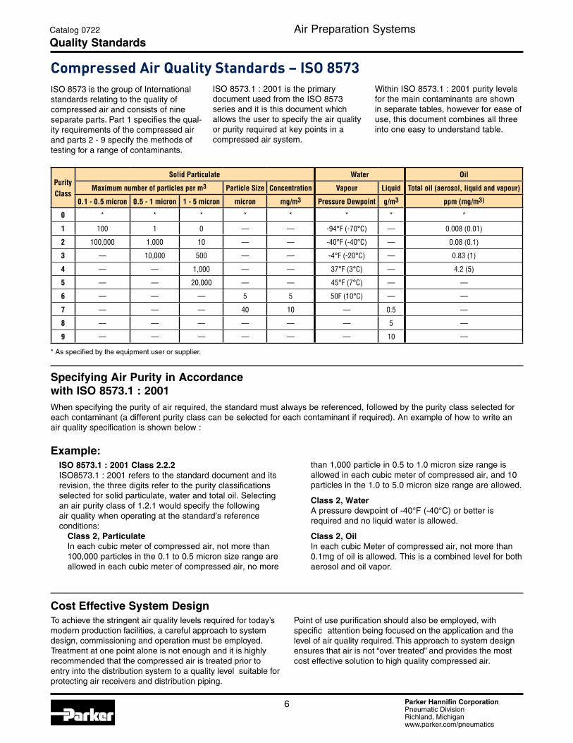
ISO 8573.1 : 2001 is the primary document used from the ISO 8573 series and it is this document which allows the user to specify the air quality or purity required at key points in a compressed air system.
Compressed Air quality Standards – iSo 8573ISO 8573 is the group of International standards relating to the quality of compressed air and consists of nine separate parts. Part 1 specifies the qual-ity requirements of the compressed air and parts 2 - 9 specify the methods of testing for a range of contaminants.
Purity Class
Solid Particulate Water Oil
Maximum number of particles per m3 Particle Size Concentration Vapour Liquid Total oil (aerosol, liquid and vapour)
0.1 - 0.5 micron 0.5 - 1 micron 1 - 5 micron micron mg/m3 Pressure Dewpoint g/m3 ppm (mg/m3)
0 * * * * * * * *
1 100 1 0 — — -94°F (-70°C) — 0.008 (0.01)
2 100,000 1,000 10 — — -40°F (-40°C) — 0.08 (0.1)
3 — 10,000 500 — — -4°F (-20°C) — 0.83 (1)
4 — — 1,000 — — 37°F (3°C) — 4.2 (5)
5 — — 20,000 — — 45°F (7°C) — —
6 — — — 5 5 50F (10°C) — —
7 — — — 40 10 — 0.5 —
8 — — — — — — 5 —
9 — — — — — — 10 —
* As specified by the equipment user or supplier.
Within ISO 8573.1 : 2001 purity levels for the main contaminants are shown in separate tables, however for ease of use, this document combines all three into one easy to understand table.
Cost Effective System DesignTo achieve the stringent air quality levels required for today’s modern production facilities, a careful approach to system design, commissioning and operation must be employed. Treatment at one point alone is not enough and it is highly recommended that the compressed air is treated prior to entry into the distribution system to a quality level suitable for protecting air receivers and distribution piping.
Point of use purification should also be employed, with specific attention being focused on the application and the level of air quality required. This approach to system design ensures that air is not “over treated” and provides the most cost effective solution to high quality compressed air.
Specifying Air Purity in Accordance with ISO 8573.1 : 2001When specifying the purity of air required, the standard must always be referenced, followed by the purity class selected for each contaminant (a different purity class can be selected for each contaminant if required). An example of how to write an air quality specification is shown below :
Example:ISO 8573.1 : 2001 Class 2.2.2ISO8573.1 : 2001 refers to the standard document and its revision, the three digits refer to the purity classifications selected for solid particulate, water and total oil. Selecting an air purity class of 1.2.1 would specify the following air quality when operating at the standard’s reference conditions:
Class 2, Particulate In each cubic meter of compressed air, not more than 100,000 particles in the 0.1 to 0.5 micron size range are allowed in each cubic meter of compressed air, no more
than 1,000 particle in 0.5 to 1.0 micron size range is allowed in each cubic meter of compressed air, and 10 particles in the 1.0 to 5.0 micron size range are allowed.
Class 2, Water A pressure dewpoint of -40°F (-40°C) or better is required and no liquid water is allowed.
Class 2, Oil In each cubic Meter of compressed air, not more than 0.1mg of oil is allowed. This is a combined level for both aerosol and oil vapor.
Parker Hannifin CorporationPneumatic DivisionRichland, Michiganwww.parker.com/pneumatics
7
Air Preparation SystemsCatalog 0722
Purity Level
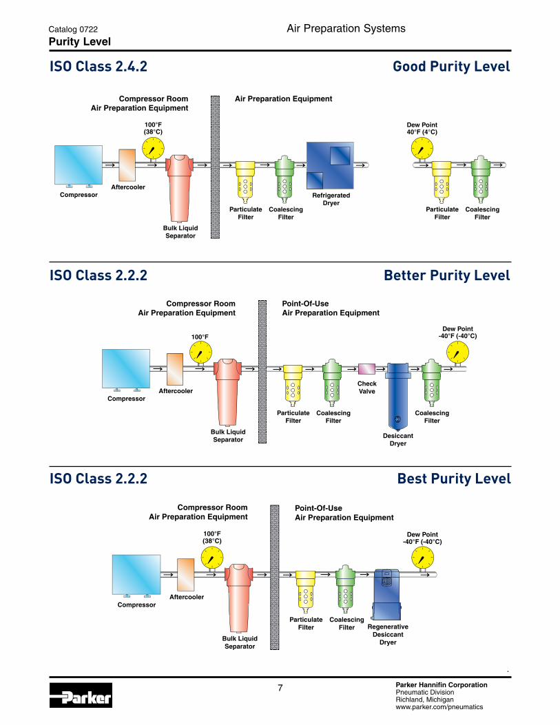
iSo Class 2.4.2 Good Purity level
iSo Class 2.2.2 Better Purity level
iSo Class 2.2.2 Best Purity level
CompressorAftercooler
100°F
Bulk LiquidSeparator
CheckValve
DesiccantDryer
Compressor RoomAir Preparation Equipment
Point-Of-UseAir Preparation Equipment
ParticulateFilter
CoalescingFilter
CoalescingFilter
Dew Point-40°F (-40°C)
Compressor
Compressor RoomAir Preparation Equipment
Air Preparation Equipment
Aftercooler
100°F(38°C)
Bulk LiquidSeparator
Dew Point40°F (4°C)
ParticulateFilter
CoalescingFilter
ParticulateFilter
CoalescingFilter
RefrigeratedDryer
ParticulateFilter
CoalescingFilter Regenerative
DesiccantDryer
Point-Of-UseAir Preparation Equipment
Compressor
Compressor RoomAir Preparation Equipment
Aftercooler
100°F(38°C)
Bulk LiquidSeparator
Dew Point-40°F (-40°C)
Parker Hannifin CorporationPneumatic DivisionRichland, Michiganwww.parker.com/pneumatics
8
Air Preparation Systems1/4" thru 3"
Catalog 0722
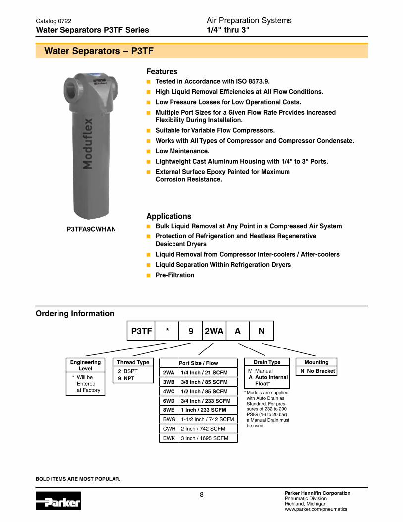
Water Separators P3TF Series
Ordering Information
BOLD ITEMS ARE MOST POPULAR.
P3TF * 9 2WA A N
Thread Type
2 BSPT 9 NPT
Drain Type
M Manual A Auto Internal Float*
Engineering Level
* Will be Entered at Factory
Mounting
N No Bracket
Featuresn Tested in Accordance with ISO 8573.9.
n High Liquid Removal Efficiencies at All Flow Conditions.
n Low Pressure Losses for Low Operational Costs.
n Multiple Port Sizes for a Given Flow Rate Provides Increased Flexibility During Installation.
n Suitable for Variable Flow Compressors.
n Works with All Types of Compressor and Compressor Condensate.
n Low Maintenance.
n Lightweight Cast Aluminum Housing with 1/4" to 3" Ports.
n External Surface Epoxy Painted for Maximum Corrosion Resistance.
Applications n Bulk Liquid Removal at Any Point in a Compressed Air System
n Protection of Refrigeration and Heatless Regenerative Desiccant Dryers
n Liquid Removal from Compressor Inter-coolers / After-coolers
n Liquid Separation Within Refrigeration Dryers
n Pre-Filtration
* Models are supplied with Auto Drain as Standard. For pres-sures of 232 to 290 PSIG (16 to 20 bar) a Manual Drain must be used.
Water Separators – P3TF
P3TFA9CWHAN
Port Size / Flow
2WA 1/4 Inch / 21 SCFM
3WB 3/8 Inch / 85 SCFM
4WC 1/2 Inch / 85 SCFM
6WD 3/4 Inch / 233 SCFM
8WE 1 Inch / 233 SCFM
BWG 1-1/2 Inch / 742 SCFM
CWH 2 Inch / 742 SCFM
EWK 3 Inch / 1695 SCFM

Parker Hannifin CorporationPneumatic DivisionRichland, Michiganwww.parker.com/pneumatics
9
Air Preparation SystemsWater Separators P3TF Series
Catalog 0722
Operation
Operation
n Air Enters the Water Separator Inlet and Turns Into the Separator Module.
n The Inlet of the Separator Module Contains a Set of Fixed Vanes Which the Air Must Pass Through.
n The Vanes Force the Air to Spin Inside the Vessel.
n The Spinning Air is Then Forced to Change Direction as it Passes the Impinger.
n A Vortex is Created Which, Due to the Design of the Separator Module, Narrows and Intensifies as it Reaches the Lower Part of the Separator Module.
n Bulk Liquid is Removed From the Airstream Due to: •DirectionalChangesoftheAirstream •VelocityChanges •CentrifugalActionoftheVortex
n As the Vortex Reaches the Bottom of the Module, Air is Forced Through The Center of the Vortex.
n Aerospace Turning Vanes, Located in the Outlet of the Separator Module, Turn an Inefficient Corner Into a Number of More Efficient Corners.
n Turning Vanes Reduce Turbulence, Minimizing Pressure Loss and Cost of Ownership.
n The Number of Vanes Required is Dependent Upon the Conduit Diameter.
Vanes
Impinger
Parker Hannifin CorporationPneumatic DivisionRichland, Michiganwww.parker.com/pneumatics
10
Air Preparation SystemsWater Separators
Catalog 0722
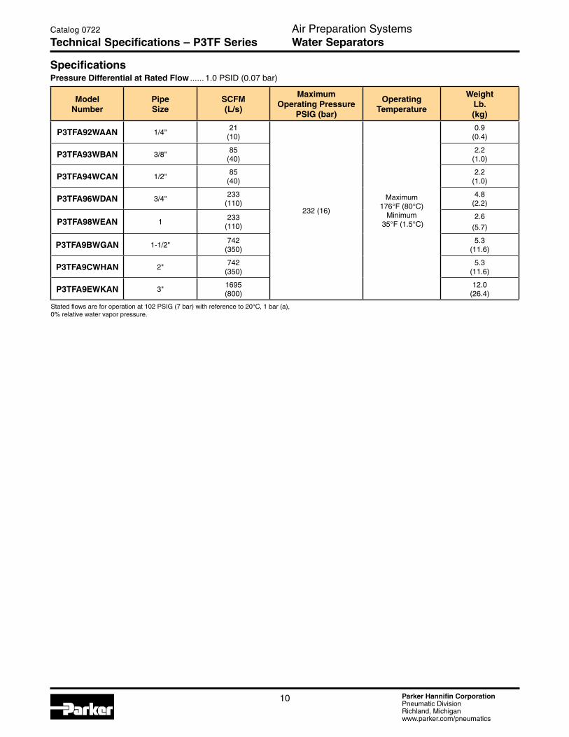
Technical Specifications – P3TF Series
SpecificationsPressure Differential at Rated Flow ...... 1.0 PSID (0.07 bar)
Model Number
Pipe Size
SCFM (L/s)
MaximumOperating Pressure
PSIG (bar)
Operating Temperature
Weight Lb. (kg)
P3TFA92WAAN 1/4"21
(10)
232 (16)
Maximum 176°F (80°C)
Minimum 35°F (1.5°C)
0.9 (0.4)
P3TFA93WBAN 3/8"85
(40)2.2
(1.0)
P3TFA94WCAN 1/2"85
(40)2.2
(1.0)
P3TFA96WDAN 3/4"233
(110)4.8
(2.2)
P3TFA98WEAN 1233
(110)2.6
(5.7)
P3TFA9BWGAN 1-1/2"742
(350)5.3
(11.6)
P3TFA9CWHAN 2"742
(350)5.3
(11.6)
P3TFA9EWKAN 3"1695(800)
12.0 (26.4)
Stated flows are for operation at 102 PSIG (7 bar) with reference to 20°C, 1 bar (a), 0% relative water vapor pressure.
Parker Hannifin CorporationPneumatic DivisionRichland, Michiganwww.parker.com/pneumatics
11
Air Preparation SystemsWater Separators
Catalog 0722
Technical Specifications – P3TF Series
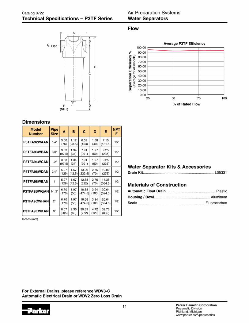
Flow
Water Separator Kits & AccessoriesDrain Kit ...................................................................... L05331
Materials of ConstructionAutomatic Float Drain ................................................ Plastic
Housing / Bowl ....................................................... Aluminum
Seals ..................................................................Fluorocarbon
For External Drains, please reference WDV3-G Automatic Electrical Drain or WDV2 Zero Loss Drain
% of Rated Flow
Average P3TF Efficiency
Sep
arat
ion
Eff
icie
ncy
%(A
vera
ge fo
r al
l mod
els)
250.00
10.00
20.00
30.00
40.00
50.00
60.00
70.00
80.00
90.00
100.00
75 10050
A
B
C
E
DF(NPT)
PipeCL
DimensionsModel
NumberPipe Size
A B C D ENPT
F
P3TFA92WAAN 1/4"3.00 (76)
1.12 (28.5)
6.02 (153)
1.58 (40)
7.15 (181.5)
1/2
P3TFA93WBAN 3/8"3.83
(97.5)1.34 (34)
7.91 (201)
1.97 (50)
9.25 (235)
1/2
P3TFA94WCAN 1/2"3.83
(97.5)1.34 (34)
7.91 (201)
1.97 (50)
9.25 (235)
1/2
P3TFA96WDAN 3/4"5.07 (129)
1.67 (42.5)
13.09 (232.5)
2.76 (70)
10.80 (275)
1/2
P3TFA98WEAN 15.07 (129)
1.67 (42.5)
12.68 (322)
2.76 (70)
14.35 (364.5)
1/2
P3TFA9BWGAN 1-1/2"6.70 (170)
1.97 (50)
18.68 (474.5)
3.94 (100)
20.64 (524.5)
1/2
P3TFA9CWHAN 2"6.70 (170)
1.97 (50)
18.68 (474.5)
3.94 (100)
20.64 (524.5)
1/2
P3TFA9EWKAN 3"8.07 (205)
2.36 (60)
30.39 (772)
4.72 (120)
32.76 (832)
1/2
Inches (mm)
Parker Hannifin CorporationPneumatic DivisionRichland, Michiganwww.parker.com/pneumatics
12
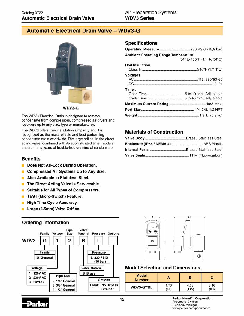
SpecificationsOperating Pressure ............................... 230 PSIG (15,9 bar)
Ambient Operating Range Temperature: 34° to 130°F (1.1° to 54°C)
Coil Insulation Class H .......................................................340°F (171.1°C)
Voltages AC ................................................................115, 230/50-60 DC .............................................................................. 12, 24
Timer: Open Time ................................... .5 to 10 sec., Adjustable Cycle Time ................................... .5 to 45 min., Adjustable
Maximum Current Rating .....................................4mA Max.
Port Size ..................................................... 1/4, 3/8, 1/2 NPT
Weight ............................................................. 1.8 lb. (0.8 kg)
Materials of ConstructionValve Body .........................................Brass / Stainless Steel
Enclosure (IP65 / NEMA 4) ................................ ABS Plastic
Internal Parts ....................................Brass / Stainless Steel
Valve Seals ............................................ FPM (Fluorocarbon)
Automatic Electrical Drain Valve – WDV3-G
WDV3-G
A
B
C
ON OFFTEST
510 20 30
40450.6 ohm
24 6
8100.5 0
The WDV3 Electrical Drain is designed to remove condensate from compressors, compressed air dryers and receivers up to any size, type or manufacturer.
The WDV3 offers true installation simplicity and it is recognized as the most reliable and best performing condensate drain worldwide. The large orifice in the direct acting valve, combined with its sophisticated timer module ensure many years of trouble-free draining of condensate.
Air Preparation Systems WDV3 Series
Catalog 0722
Automatic Electrical Drain Valve
Pipe Valve Family Voltage Size Material Pressure Options
WDV3 – G 1 2 B L —
Pressure
L 230 PSIG (16 bar)
Valve Material
B Brass
Options
Blank No Bypass Strainer
Family
G General
Voltage
1 120V AC 2 230V AC 3 24VDC
Pipe Size
2 1/4" General 3 3/8" General 4 1/2" General
Ordering Information
Model Selection and Dimensions
ModelNumber
A B C
WDV3-G**BL 1.73(44)
4.53(115)
3.46(88)
Benefitsn Does Not Air-Lock During Operation.
n Compressed Air Systems Up to Any Size.
n Also Available In Stainless Steel.
n The Direct Acting Valve Is Serviceable.
n Suitable for All Types of Compressors.
n TEST (Micro-Switch) Feature.
n High Time Cycle Accuracy.
n Large (4.5mm) Valve Orifice.
Parker Hannifin CorporationPneumatic DivisionRichland, Michiganwww.parker.com/pneumatics
13
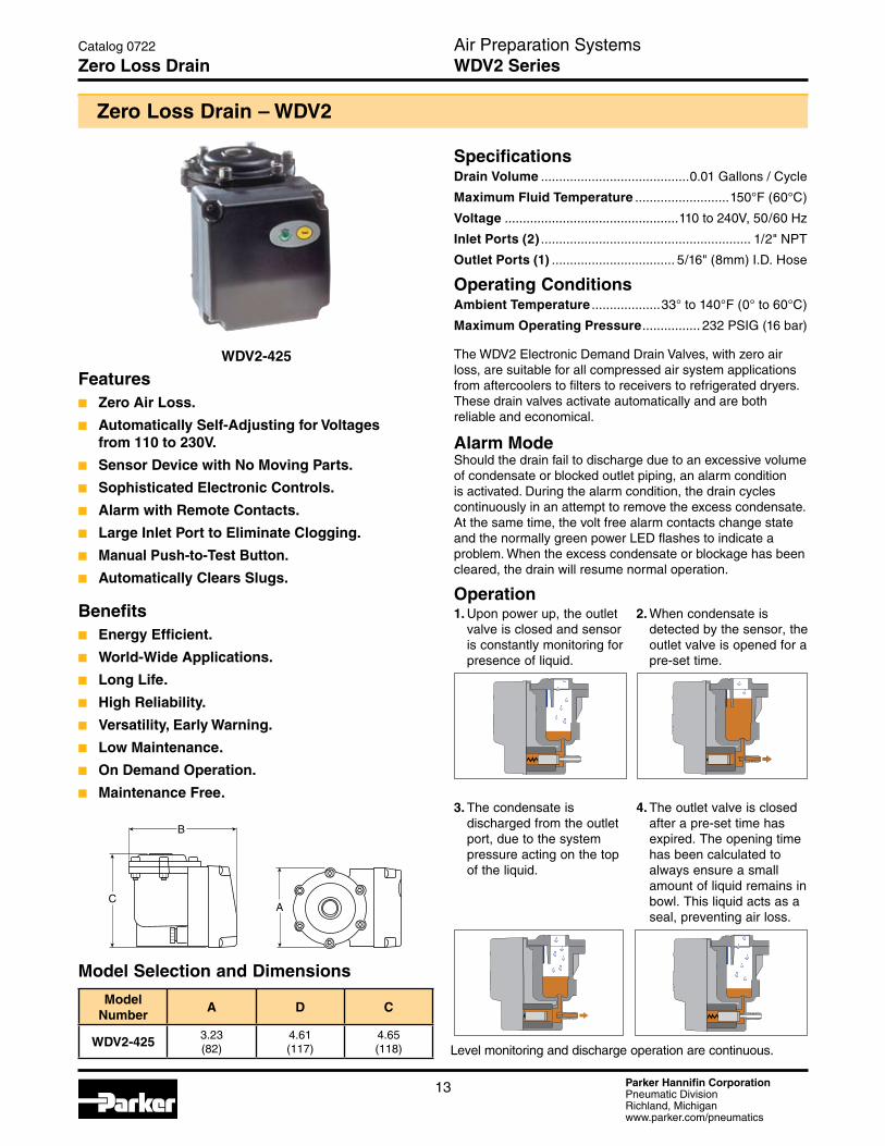
The WDV2 Electronic Demand Drain Valves, with zero air loss, are suitable for all compressed air system applications from aftercoolers to filters to receivers to refrigerated dryers. These drain valves activate automatically and are both reliable and economical.
Alarm ModeShould the drain fail to discharge due to an excessive volume of condensate or blocked outlet piping, an alarm condition is activated. During the alarm condition, the drain cycles continuously in an attempt to remove the excess condensate. At the same time, the volt free alarm contacts change state and the normally green power LED flashes to indicate a problem. When the excess condensate or blockage has been cleared, the drain will resume normal operation.
Operation
Zero Loss Drain – WDV2
SpecificationsDrain Volume .........................................0.01 Gallons / Cycle
Maximum Fluid Temperature ..........................150°F (60°C)
Voltage ................................................110 to 240V, 50/60 Hz
Inlet Ports (2) .......................................................... 1/2" NPT
Outlet Ports (1) .................................. 5/16" (8mm) I.D. Hose
Operating ConditionsAmbient Temperature ...................33° to 140°F (0° to 60°C)
Maximum Operating Pressure ................ 232 PSIG (16 bar)
Featuresn Zero Air Loss.
n Automatically Self-Adjusting for Voltages from 110 to 230V.
n Sensor Device with No Moving Parts.
n Sophisticated Electronic Controls.
n Alarm with Remote Contacts.
n Large Inlet Port to Eliminate Clogging.
n Manual Push-to-Test Button.
n Automatically Clears Slugs.
Benefitsn Energy Efficient.
n World-Wide Applications.
n Long Life.
n High Reliability.
n Versatility, Early Warning.
n Low Maintenance.
n On Demand Operation.
n Maintenance Free.
WDV2-425
C
B
A
Air Preparation SystemsWDV2 Series
Catalog 0722
Zero Loss Drain
Model Selection and Dimensions
ModelNumber
A D C
WDV2-425 3.23(82)
4.61(117)
4.65(118)
1. Upon power up, the outlet valve is closed and sensor is constantly monitoring for presence of liquid.
2. When condensate is detected by the sensor, the outlet valve is opened for a pre-set time.
3. The condensate is discharged from the outlet port, due to the system pressure acting on the top of the liquid.
4. The outlet valve is closed after a pre-set time has expired. The opening time has been calculated to always ensure a small amount of liquid remains in bowl. This liquid acts as a seal, preventing air loss.
Level monitoring and discharge operation are continuous.
Parker Hannifin CorporationPneumatic DivisionRichland, Michiganwww.parker.com/pneumatics
14
Refrigeration Dryers – PDRD
Air Preparation SystemsPDRD Series
Catalog 0722
Refrigeration Dryers PDRD Series
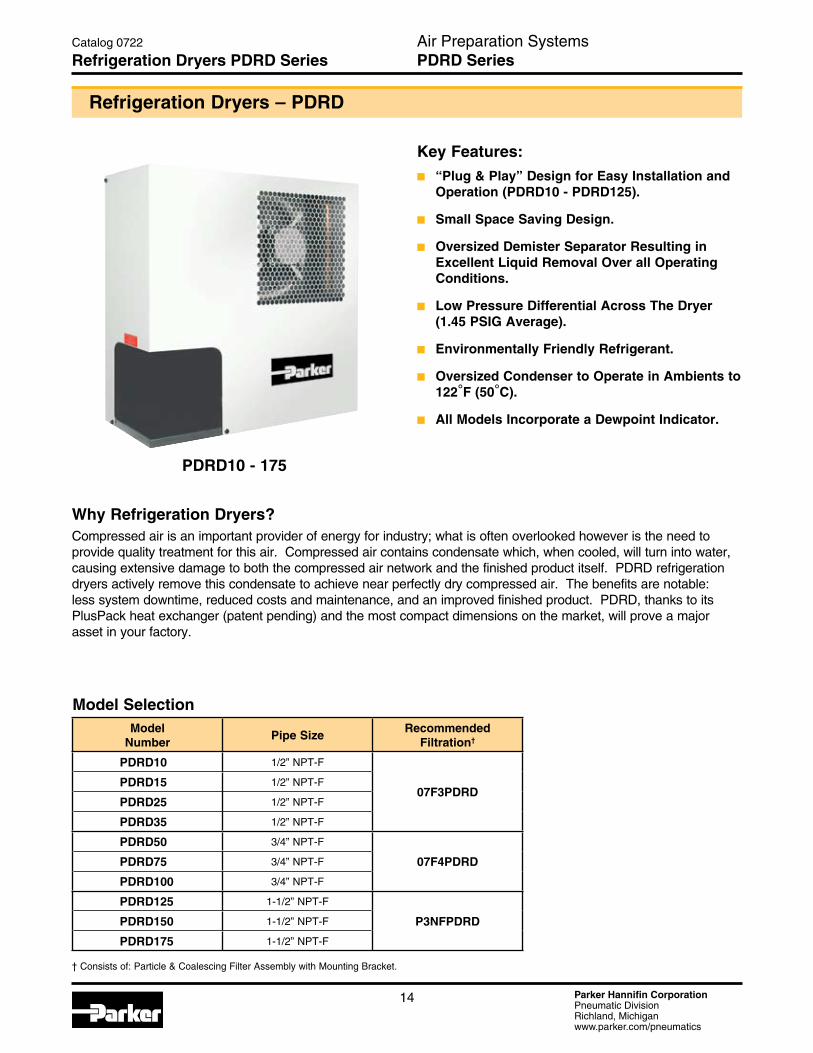
PDRD10 - 175
Key Features: n “Plug & Play” Design for Easy Installation and
Operation (PDRD10 - PDRD125).
n Small Space Saving Design.
n Oversized Demister Separator Resulting in Excellent Liquid Removal Over all Operating Conditions.
n Low Pressure Differential Across The Dryer (1.45 PSIG Average).
n Environmentally Friendly Refrigerant.
n Oversized Condenser to Operate in Ambients to 122°F (50°C).
n All Models Incorporate a Dewpoint Indicator.
Why Refrigeration Dryers?Compressed air is an important provider of energy for industry; what is often overlooked however is the need to provide quality treatment for this air. Compressed air contains condensate which, when cooled, will turn into water, causing extensive damage to both the compressed air network and the finished product itself. PDRD refrigeration dryers actively remove this condensate to achieve near perfectly dry compressed air. The benefits are notable: less system downtime, reduced costs and maintenance, and an improved finished product. PDRD, thanks to its PlusPack heat exchanger (patent pending) and the most compact dimensions on the market, will prove a major asset in your factory.
Model SelectionModel
NumberPipe Size
Recommended Filtration†
PDRD10 1/2” NPT-F
07F3PDRDPDRD15 1/2” NPT-F
PDRD25 1/2” NPT-F
PDRD35 1/2” NPT-F
PDRD50 3/4” NPT-F
07F4PDRDPDRD75 3/4” NPT-F
PDRD100 3/4” NPT-F
PDRD125 1-1/2” NPT-F
P3NFPDRDPDRD150 1-1/2” NPT-F
PDRD175 1-1/2” NPT-F
† Consists of: Particle & Coalescing Filter Assembly with Mounting Bracket.
Parker Hannifin CorporationPneumatic DivisionRichland, Michiganwww.parker.com/pneumatics
15
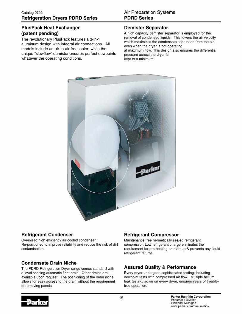
PlusPack Heat Exchanger (patent pending)The revolutionary PlusPack features a 3-in-1 aluminum design with integral air connections. All models include an air-to-air freecooler, while the unique “slowflow” demister ensures perfect dewpoints whatever the operating conditions.
Demister SeparatorA high capacity demister separator is employed for the removal of condensed liquids. This lowers the air velocity which maximizes the condensate separation from the air, even when the dryer is not operating at maximum flow. This design also ensures the differential pressure across the dryer is kept to a minimum.
Refrigerant CondenserOversized high efficiency air cooled condenser. Re-positioned to improve reliability and reduce the risk of dirt contamination.
Refrigerant CompressorMaintenance free hermetically sealed refrigerant compressor. Low refrigerant charge eliminates the requirement for pre-heating on start up & prevents any liquid refrigerant returns.
Assured Quality & PerformanceEvery dryer undergoes sophisticated testing, including dewpoint tests with compressed air flow. Multiple helium leak testing, again on every dryer, ensures years of trouble-free operation.
Condensate Drain NicheThe PDRD Refrigeration Dryer range comes standard with a level sensing automatic float drain. Other drains are available upon request. The positioning of the drain niche allows for easy access to the drain without the requirement of removing panels.
Air Preparation SystemsPDRD Series
Catalog 0722
Refrigeration Dryers PDRD Series
Parker Hannifin CorporationPneumatic DivisionRichland, Michiganwww.parker.com/pneumatics
16
Sep
arat
ion
Eff
icie
ncy
slowflow demister moisture removal
demister separator
centrifugal separator
Air
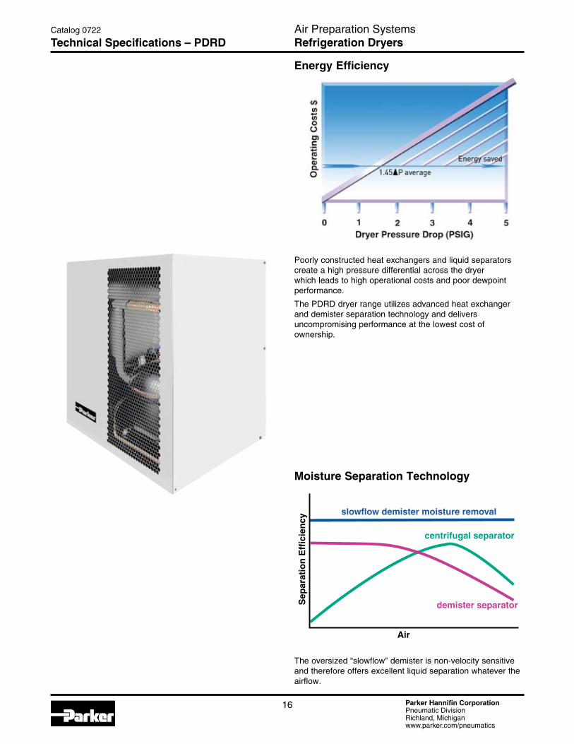
Energy Efficiency
Poorly constructed heat exchangers and liquid separators create a high pressure differential across the dryer which leads to high operational costs and poor dewpoint performance.
The PDRD dryer range utilizes advanced heat exchanger and demister separation technology and delivers uncompromising performance at the lowest cost of ownership.
Catalog 0722
Technical Specifications – PDRDAir Preparation SystemsRefrigeration Dryers
The oversized “slowflow” demister is non-velocity sensitive and therefore offers excellent liquid separation whatever the airflow.
Moisture Separation Technology

Parker Hannifin CorporationPneumatic DivisionRichland, Michiganwww.parker.com/pneumatics
17
Catalog 0722
Technical Specifications – PDRDAir Preparation SystemsRefrigeration Dryers
Maximum Ambient Temperature .......................... 122°F (50°C)
Maximum Inlet Temperature – Models PDRD10 thru PDRD175: .................. 149°F (65°C)
Minimum Ambient Temperature ............................... 41°F (5°C)
Maximum Inlet Pressure – Models PDRD10 thru PDRD175: ..........232 PSIG (16 bar)
Refrigerant – Models PDRD10 thru PDRD175: .............................R134a
Model Number
Pipe SizeNominal Flow*
Primary Voltages
Recommended Filtration†SCFM Nm3/hr Nm3/min
PDRD10-115 1/2” NPT-F 10 17 0.3 115V/1ph/60Hz
07F3PDRDPDRD15-115 1/2” NPT-F 15 26 0.4 115V/1ph/60Hz
PDRD25-115 1/2” NPT-F 25 43 0.7 115V/1ph/60Hz
PDRD35-115 1/2” NPT-F 35 60 1.0 115V/1ph/60Hz
PDRD50-115 3/4” NPT-F 50 85 1.4 115V/1ph/60Hz
07F4PDRDPDRD75-115 3/4” NPT-F 75 127 2.1 115V/1ph/60Hz
PDRD100-115 3/4” NPT-F 100 170 2.8 115V/1ph/60Hz
PDRD125-115PDRD125-230
1-1/2” NPT-F 125 212 3.5115V/1ph/60Hz & 230V/1ph/60Hz
P3NFPDRDPDRD150-115 PDRD150-230
1-1/2” NPT-F 150 255 4.2115V/1ph/60Hz & 230V/1ph/60Hz
PDRD175-115 PDRD175-230
1-1/2” NPT-F 175 297 5.0 230V/1ph/60Hz
† Consists of: Particle & Coalescing Filter Assembly with Mounting Bracket.
Technical Information
*Capacities are based upon:Ambient Temperature .............................................................100°F (38°C)Inlet Temperature .................................................................. 100°F (38°C) Working Pressure ............................................................ 100 PSIG (7 bar)
Parker Hannifin CorporationPneumatic DivisionRichland, Michiganwww.parker.com/pneumatics
18
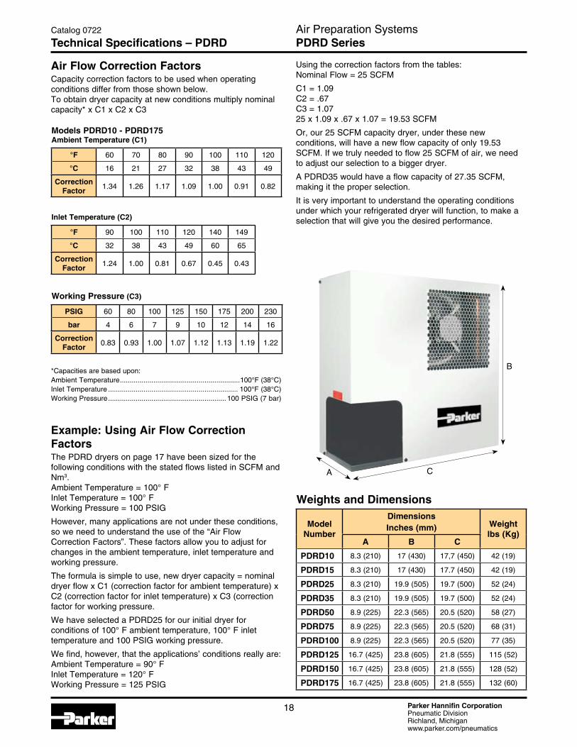
Models PDRD10 - PDRD175 Ambient Temperature (C1)
°F 60 70 80 90 100 110 120
°C 16 21 27 32 38 43 49
Correction Factor
1.34 1.26 1.17 1.09 1.00 0.91 0.82
Working Pressure (C3)
PSIG 60 80 100 125 150 175 200 230
bar 4 6 7 9 10 12 14 16
Correction Factor
0.83 0.93 1.00 1.07 1.12 1.13 1.19 1.22
Inlet Temperature (C2)
°F 90 100 110 120 140 149
°C 32 38 43 49 60 65
Correction Factor
1.24 1.00 0.81 0.67 0.45 0.43
Air Flow Correction FactorsCapacity correction factors to be used when operating conditions differ from those shown below. To obtain dryer capacity at new conditions multiply nominal capacity* x C1 x C2 x C3
Weights and Dimensions
Model Number
DimensionsInches (mm) Weight
lbs (Kg)A B C
PDRD10 8.3 (210) 17 (430) 17,7 (450) 42 (19)
PDRD15 8.3 (210) 17 (430) 17.7 (450) 42 (19)
PDRD25 8.3 (210) 19.9 (505) 19.7 (500) 52 (24)
PDRD35 8.3 (210) 19.9 (505) 19.7 (500) 52 (24)
PDRD50 8.9 (225) 22.3 (565) 20.5 (520) 58 (27)
PDRD75 8.9 (225) 22.3 (565) 20.5 (520) 68 (31)
PDRD100 8.9 (225) 22.3 (565) 20.5 (520) 77 (35)
PDRD125 16.7 (425) 23.8 (605) 21.8 (555) 115 (52)
PDRD150 16.7 (425) 23.8 (605) 21.8 (555) 128 (52)
PDRD175 16.7 (425) 23.8 (605) 21.8 (555) 132 (60)
B
CA
Air Preparation SystemsPDRD Series
Catalog 0722
Technical Specifications – PDRD
*Capacities are based upon:Ambient Temperature .............................................................100°F (38°C)Inlet Temperature .................................................................. 100°F (38°C) Working Pressure ............................................................ 100 PSIG (7 bar)
Example: Using Air Flow Correction FactorsThe PDRD dryers on page 17 have been sized for the following conditions with the stated flows listed in SCFM and Nm3. Ambient Temperature = 100° F Inlet Temperature = 100° F Working Pressure = 100 PSIG
However, many applications are not under these conditions, so we need to understand the use of the “Air Flow Correction Factors”. These factors allow you to adjust for changes in the ambient temperature, inlet temperature and working pressure.
The formula is simple to use, new dryer capacity = nominal dryer flow x C1 (correction factor for ambient temperature) x C2 (correction factor for inlet temperature) x C3 (correction factor for working pressure.
We have selected a PDRD25 for our initial dryer for conditions of 100° F ambient temperature, 100° F inlet temperature and 100 PSIG working pressure.
We find, however, that the applications’ conditions really are: Ambient Temperature = 90° F Inlet Temperature = 120° F Working Pressure = 125 PSIG
Using the correction factors from the tables: Nominal Flow = 25 SCFM
C1 = 1.09 C2 = .67 C3 = 1.07 25 x 1.09 x .67 x 1.07 = 19.53 SCFM
Or, our 25 SCFM capacity dryer, under these new conditions, will have a new flow capacity of only 19.53 SCFM. If we truly needed to flow 25 SCFM of air, we need to adjust our selection to a bigger dryer.
A PDRD35 would have a flow capacity of 27.35 SCFM, making it the proper selection.
It is very important to understand the operating conditions under which your refrigerated dryer will function, to make a selection that will give you the desired performance.
Parker Hannifin CorporationPneumatic DivisionRichland, Michiganwww.parker.com/pneumatics
19
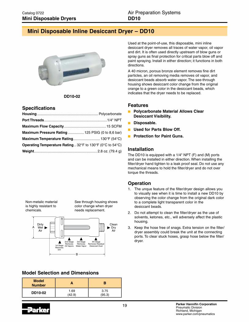
Used at the point-of-use, this disposable, mini inline desiccant dryer removes all traces of water vapor, oil vapor and dirt. It is often used directly upstream of blow guns or spray guns as final protection for critical parts blow off and paint spraying. Install in either direction; it functions in both directions.
A 40 micron, porous bronze element removes fine dirt particles, an oil removing media removes oil vapor, and desiccant beads absorb water vapor. The see-through housing shows desiccant color change from the original orange to a green color in the desiccant beads, which indicates that the dryer needs to be replaced.
Featuresn Polycarbonate Material Allows Clear
Desiccant Visibility.
n Disposable.
n Used for Parts Blow Off.
n Protection for Paint Guns.
InstallationThe DD10 is equipped with a 1/4" NPT (F) and (M) ports and can be installed in either direction. When installing the filter/dryer hand tighten to a leak proof seal. Do not use any mechanical means to hold the filter/dryer and do not over torque the threads.
Operation1. The unque feature of the filter/dryer design allows you
to visually see when it is time to install a new DD10 by observing the color change from the original dark color to a complete light transparent color in the desiccant beads.
2. Do not attempt to clean the filter/dryer as the use of solvents, ketones, etc., will adversely affect the plastic housing.
3. Keep the hose free of snags. Extra tension on the filter/dryer assembly could break the unit at the connecting ports. To clear stuck hoses, grasp hose below the filter/dryer.
Mini Disposable Inline Desiccant Dryer – DD10
SpecificationsHousing ............................................................. Polycarbonate
Port Threads ...............................................................1/4" NPT
Maximum Flow Capacity ..........................................15 SCFM
Maximum Pressure Rating ................125 PSIG (0 to 8,6 bar)
Maximum Temperature Rating ...........................130°F (54°C)
Operating Temperature Rating .. 32°F to 130°F (0°C to 54°C)
Weight ............................................................... 2.8 oz. (79.4 g)
B
ACleanDryAir
DirtyWetAir
See through housing shows color change when dryer needs replacement.
Non-metalic material is highly resistant to chemicals.
2nd StageRemovesOil Vapors
3rd StageRemoves
Water Vapor
4th StageRemoves Residual
Desiccant Dust1st StageRemoves
Dirt
DD10-02
Air Preparation Systems DD10
Catalog 0722
Mini Disposable Dryers
Model Selection and Dimensions
ModelNumber
A B
DD10-02 1.69(42.9)
3.75(95.3)

Parker Hannifin CorporationPneumatic DivisionRichland, Michiganwww.parker.com/pneumatics
20
Model SelectionPort Size 15 SCFM 30 SCFM 60 SCFM
DesiccantCapacity¹
2.5 lb¹ 5 lb.¹ 10 lb.¹
1/4" ² DD15-02 N/A N/A
3/8" ² DD15-03 N/A N/A
1/2" ² DD DD30-04 DD60-04
3/4" DD15-06 DD30-06 DD60-06
1" N/A DD30-08 DD60-08
Notes:
1. Desiccant must be ordered separately.
2.These units supplied with reducer bushings.
Featuresn These Inline Desiccant Dryers are a
Convenient and Cost Effective Means of Ensuring Your Sensitive Pneumatic Applications are Never Exposed to Damaging Moisture.
n Compact Size for Point-Of-Use Applications.
n Drying Efficiency Down to -40°F Pressure Dew Point.
n Easily and Quickly Serviced.
n Sightglass in Bowl to Monitor Desiccant.
n Built-In Particulate After Filter Prevents Downstream Dust.
n No Electricity Needed.
n Low Pressure Drop.
n No Purge Air Lost as with Other Dryer Types.
DD Inline Desiccant Dryers
DimensionsModel
NumberA B C D* E
DD15 4.94(125)
12.69(322)
.84(21)
4.06(103)
13.5(343)
DD30 4.94(125)
22.44(570)
.84(21)
4.06(103)
23.25(591)
DD60 4.94(125)
29.44(748)
.84(21)
4.06(103)
30.25(768)
* Dimension does not include reducer bushings for 1/4", 3/8", 1/2" versions.Inches (mm)
AD
C
BE
Applications n Paint Spraying
n Instrument Air
n Laboratory Instruments
n Control Air Systems
n Air Blanketing
PerformanceThe rated flow capacities are nominal ratings provided for reference. These capacities are recommended for minimal pressure drop and average desiccant life. A supply of low flow / low humidity air will provide longer desiccant life: whereas, high flow / high humidity air will require more frequent desiccant changes. Installed in an application with intermittent flow, these desiccant dryers will typically dry air for weeks before the silica gel desiccant requires replacement or regeneration.
Air Preparation Systems1/4", 3/8", 1/2", 3/4", 1"
Catalog 0722
Inline Desiccant Dryers DD Series
DD15-03
Parker Hannifin CorporationPneumatic DivisionRichland, Michiganwww.parker.com/pneumatics
21
Desiccant Dryers Kits & AccessoriesDesiccant - Silica Gel 100% Indicating –
(6) .88 lb. Bags ............................................................... SGM100-1 (24) .88 lb. Bags ............................................................. SGM100-4
Flow Tube Repair Kit (Tube, Filter Element(s), Adaptor) DD15 .......................................................................RKDD15-02-06 DD30 .......................................................................RKDD30-03-08 DD60 .......................................................................RKDD60-03-08
Mounting Brackets (Recommended for DD15 & DD30 only) – 1/4 Inch Pipe Size (Pair of Pipe Mounted Brackets) ....SA200YW57 1 Inch Pipe Size (Pair of Pipe Mounted Brackets) .......SA200CW57
Spring Check Valve for Inlet (250 PSIG max.) – (Maximizes Life of Desiccant) 1/4 Inch NPT...................................................................003393001 3/8 Inch NPT...................................................................003393002 1/2 Inch NPT...................................................................003393003 3/4 Inch NPT...................................................................003393004
SpecificationsDesiccant Capacity (Desiccant must be ordered separately) –
DD15 ...................................................................................... 2.5 lb. DD30 ......................................................................................... 5 lb. DD60 .......................................................................................10 lb.
Filter Element Rating – DD15, DD30 .....................................................................90 micron DD60 ................................................................................40 micron
Pressure & Temperature Ratings – Optimum working temperature .................................. Below 100° F Pressure Range.........................................................0 to 300 PSIG Temperature Range ................................................... 32°F to 180°F
Weight (Housing Only) – DD15 (add 2.5 lb for weight full) ...................................8 lb. (3.6 kg) DD30 (add 5 lb for weight full) ....................................13 lb. (5.9 kg) DD60 (add 10 lb for weight full) ..................................20 lb. (9.1 kg)
Materials of ConstructionBowl –
DD15, DD30 .....................................................................Aluminum DD60 ....................................................................................... Steel
Flow Tube .................................................................................CPVC
Filter Elements .........................................................Sintered Bronze
Head & Flange Ring ....................................................................Zinc
Other Hardware ........................................................................ Brass
Seals ...................................................................................... Buna-N
Sight Glass ...................................................................Glass & Steel
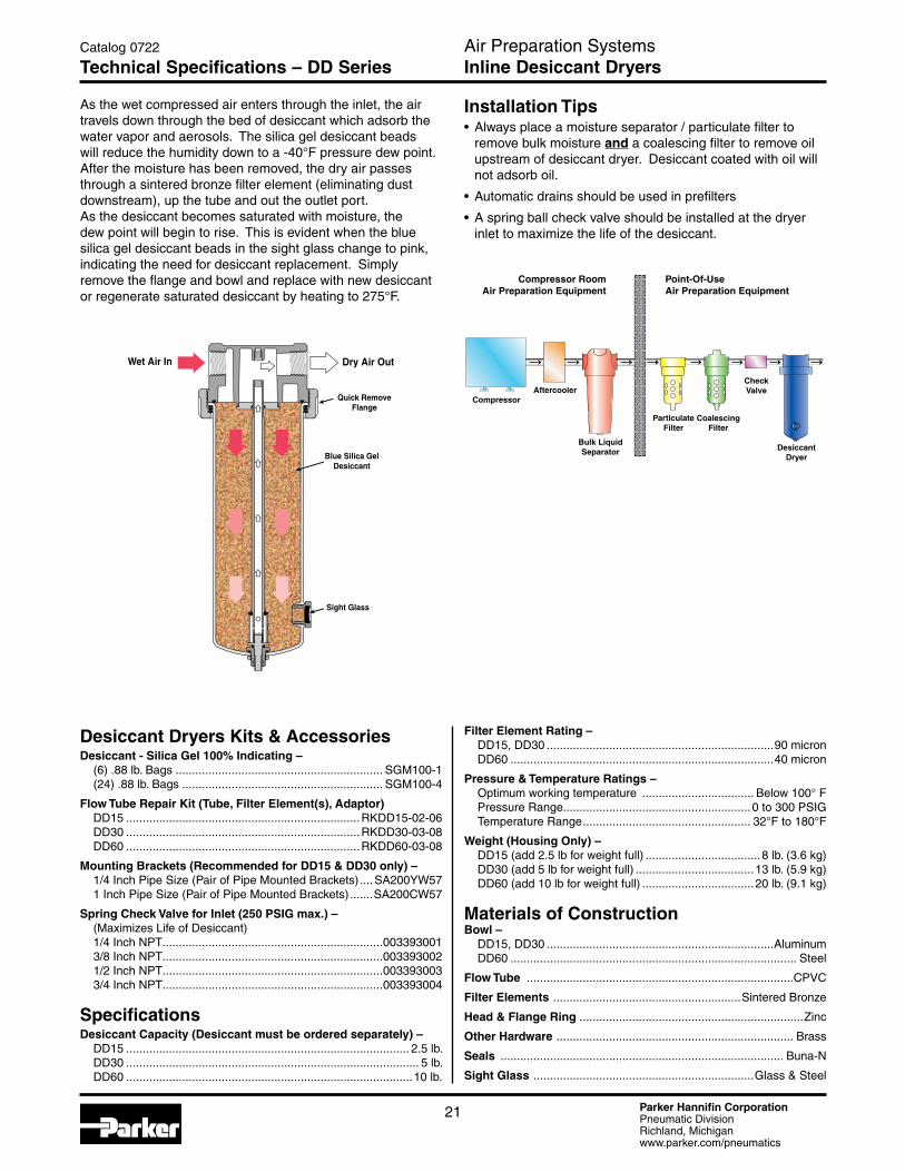
Installation Tips • Always place a moisture separator / particulate filter to
remove bulk moisture and a coalescing filter to remove oil upstream of desiccant dryer. Desiccant coated with oil will not adsorb oil.
• Automatic drains should be used in prefilters
• A spring ball check valve should be installed at the dryer inlet to maximize the life of the desiccant.
As the wet compressed air enters through the inlet, the air travels down through the bed of desiccant which adsorb the water vapor and aerosols. The silica gel desiccant beads will reduce the humidity down to a -40°F pressure dew point. After the moisture has been removed, the dry air passes through a sintered bronze filter element (eliminating dust downstream), up the tube and out the outlet port.As the desiccant becomes saturated with moisture, the dew point will begin to rise. This is evident when the blue silica gel desiccant beads in the sight glass change to pink, indicating the need for desiccant replacement. Simply remove the flange and bowl and replace with new desiccant or regenerate saturated desiccant by heating to 275°F.
Dry Air Out
Blue Silica GelDesiccant
Wet Air In
Sight Glass
Quick RemoveFlange
Air Preparation SystemsInline Desiccant Dryers
Catalog 0722
Technical Specifications – DD Series
DesiccantDryer
CompressorAftercooler
Bulk LiquidSeparator
CheckValve
Compressor RoomAir Preparation Equipment
Point-Of-UseAir Preparation Equipment
ParticulateFilter
CoalescingFilter

Parker Hannifin CorporationPneumatic DivisionRichland, Michiganwww.parker.com/pneumatics
22
Selection Criteria To correctly select the dryer best suited for your application, the following details are required to ensure optimum performance and trouble free operation.
n Maximum Inlet Flow.
n Minimum Inlet Pressure.
n Maximum Inlet Temperature.
Once these operating parameters have been established, you can select the most economical Regenerative Desiccant Dryers for your application.
BOLD ITEMS ARE MOST POPULAR.
P3TJA 9 3 A 2 J N
Thread Type
1 BSPT 9 NPT
Supply Voltage
A 230VAC J 115VAC
Size
1 (3 SCFM) 2 (5 SCFM) 3 (8 SCFM) 4 (10 SCFM) 5 (13 SCFM) 6 (15 SCFM) 7 (20 SCFM)
Air Preparation Systems P3TJA Series
Catalog 0722
Regenerative Desiccant Dryers P3TJA Series
Regenerative Desiccant Dryers – P3TJA
SpecificationsFlow Range –
3 SCFM to 20 SCFM @ 100 PSIG (85 L/min to 567 L/min @ 7 bar)
Minimum Operating Pressure ........................58 PSIG (4 bar)Maximum Operating Pressure ...................175 PSIG (12 bar)Minimum Operating Temperature .......................35°F (1.5°C)Maximum Inlet Temperature ...............................122°F (50°C)Noise Level (Average) .................................................70dB(A)Pressure Dewpoint –
Standard .................................................... -40°F (-40°C) pdp Optional .....................................................158°F (-70°C) pdp
Standard Electrical Supply – +230/1ph/50Hz (Tolerance +/- 10%) 115/1ph/60Hz (Tolerance +/- 10%)
Controls .............................................. Electronic Control TimerInlet Connections ......3/8 NPT (BSP Available upon Request)Outlet Connections ...3/8 NPT (BSP Available upon Request)
Ordering Information
Parker Hannifin CorporationPneumatic DivisionRichland, Michiganwww.parker.com/pneumatics
23
Air Preparation Systems P3TJA Series
Catalog 0722
Regenerative Desiccant Dryers P3TJA Series
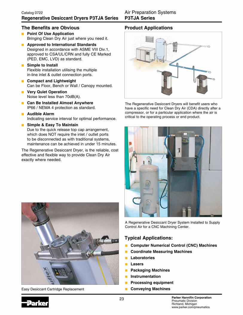
The Benefits are Obviousn Point Of Use Application
Bringing Clean Dry Air just where you need it.
n Approved to International Standards Designed in accordance with ASME VIII Div.1, approved to CSA/UL/CRN and fully CE Marked (PED, EMC, LVD) as standard.
n Simple to Install Flexible installation utilising the multiple in-line inlet & outlet connection ports.
n Compact and Lightweight Can be Floor, Bench or Wall / Canopy mounted.
n Very Quiet Operation Noise level less than 70dB(A).
n Can Be Installed Almost Anywhere IP66 / NEMA 4 protection as standard.
n Audible Alarm Indicating service interval for optimal performance.
n Simple & Easy To Maintain Due to the quick release top cap arrangement, which does NOT require the inlet / outlet ports to be disconnected as with traditional systems, maintenance can be achieved in under 15 minutes.
The Regenerative Desiccant Dryer, is the reliable, cost effective and flexible way to provide Clean Dry Air exactly where needed.
Easy Desiccant Cartridge Replacement
The Regenerative Desiccant Dryers will benefit users who have a specific need for Clean Dry Air (CDA) directly after a compressor, or for a particular application where the air is critical to the operating process or end product.
A Regenerative Desiccant Dryer System Installed to Supply Control Air for a CNC Machining Center.
n Computer Numerical Control (CNC) Machines
n Coordinate Measuring Machines
n Laboratories
n Lasers
n Packaging Machines
n Instrumentation
n Processing equipment
n Conveying Machines
Typical Applications:
Product Applications
Parker Hannifin CorporationPneumatic DivisionRichland, Michiganwww.parker.com/pneumatics
24
Features
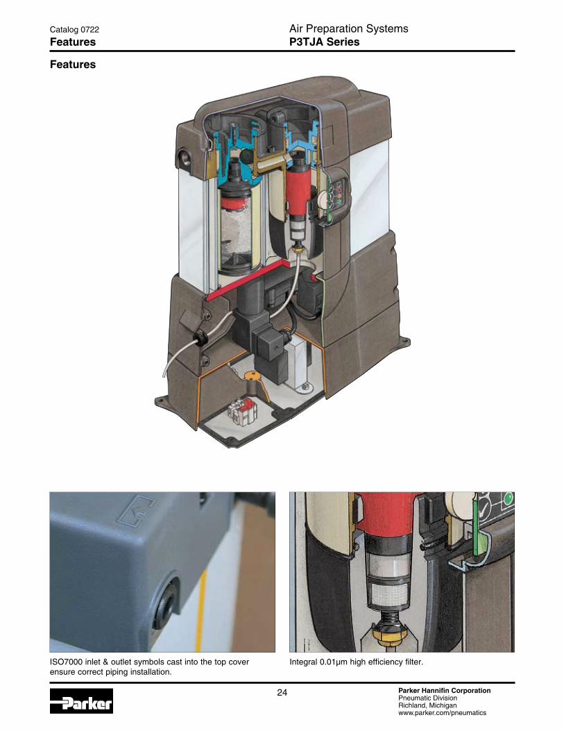
ISO7000 inlet & outlet symbols cast into the top cover ensure correct piping installation.
Integral 0.01µm high efficiency filter.
Air Preparation Systems P3TJA Series
Catalog 0722
Features
Parker Hannifin CorporationPneumatic DivisionRichland, Michiganwww.parker.com/pneumatics
25
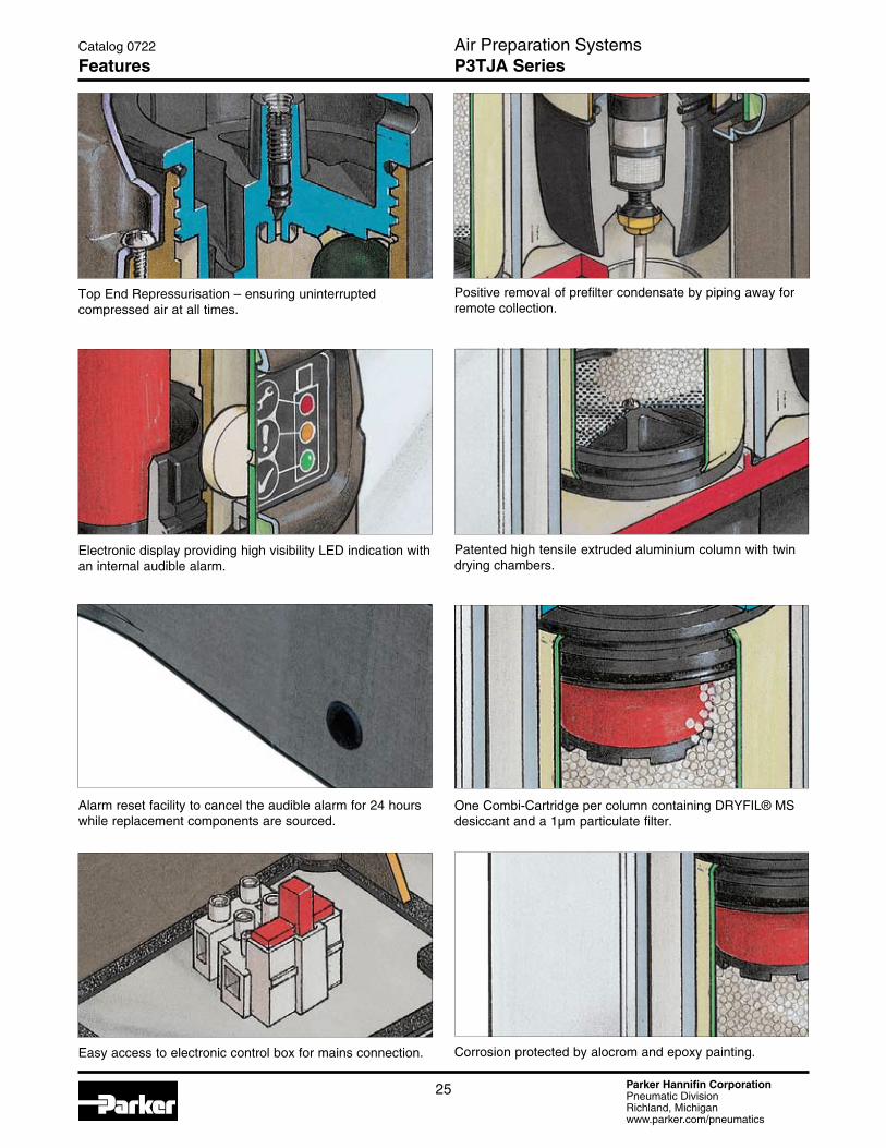
Positive removal of prefilter condensate by piping away for remote collection.
One Combi-Cartridge per column containing DRYFIL® MS desiccant and a 1µm particulate filter.
Corrosion protected by alocrom and epoxy painting.
Patented high tensile extruded aluminium column with twin drying chambers.
Top End Repressurisation – ensuring uninterrupted compressed air at all times.
Alarm reset facility to cancel the audible alarm for 24 hours while replacement components are sourced.
Easy access to electronic control box for mains connection.
Electronic display providing high visibility LED indication with an internal audible alarm.
Air Preparation Systems P3TJA Series
Catalog 0722
Features

Parker Hannifin CorporationPneumatic DivisionRichland, Michiganwww.parker.com/pneumatics
26
Air Preparation Systems P3TJA Series
Catalog 0722
Operation
Operation
Compressed air enters the integral pre-filter and passes into the left hand chamber (Column A) where the air is dried before passing to the application.
A small amount of dry purge air is used to regenerate the right hand chamber (Column B) which is wet, using the PSA (Pressure Swing Adsorption) method of regeneration, venting the saturated air to atmosphere under pressure. The same regeneration air is also used to “back flush” the integral filter to prolong its working life.
Prior to changeover, the right hand chamber (Column B) enters repressurisation where the exhaust.
This process ensures a smooth uninterrupted changeover, preventing the loss of any system pressure, before the process repeats itself.2
ColumnA
ColumnA
ColumnB
ColumnB
1
Parker Hannifin CorporationPneumatic DivisionRichland, Michiganwww.parker.com/pneumatics
27
Air Preparation Systems P3TJA Series
Catalog 0722
Optional Features
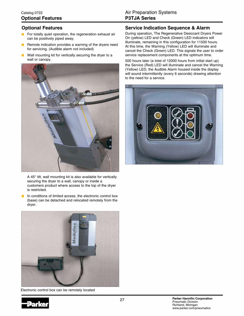
Electronic control box can be remotely located
Optional Featuresn For totally quiet operation, the regeneration exhaust air
can be positively piped away.
n Remote indication provides a warning of the dryers need for servicing. (Audible alarm not included)
n Wall mounting kit for vertically securing the dryer to a wall or canopy.
A 45° tilt, wall mounting kit is also available for vertically securing the dryer to a wall, canopy or inside a customers product where access to the top of the dryer is restricted.
n In conditions of limited access, the electronic control box (base) can be detached and relocated remotely from the dryer.
Service Indication Sequence & Alarm During operation, The Regenerative Desiccant Dryers Power On (yellow) LED and Check (Green) LED indicators will illuminate, remaining in this configuration for 11500 hours. At this time, the Warning (Yellow) LED will illuminate and cancel the Check (Green) LED. This signals the user to order service replacement components at the optimum time.
500 hours later (a total of 12000 hours from initial start up) the Service (Red) LED will illuminate and cancel the Warning (Yellow) LED, the Audible Alarm housed inside the display will sound intermittently (every 6 seconds) drawing attention to the need for a service.
Parker Hannifin CorporationPneumatic DivisionRichland, Michiganwww.parker.com/pneumatics
28
Catalog 0722
Technical Specifications – P3TJAAir Preparation Systems Dryers
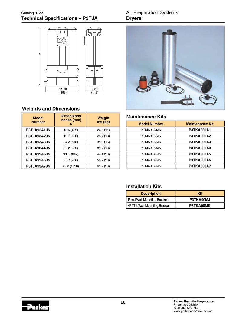
Maintenance KitsModel Number Maintenance Kit
P3TJA93A1JN P3TKA00JA1
P3TJA93A2JN P3TKA00JA2
P3TJA93A3JN P3TKA00JA3
P3TJA93A4JN P3TKA00JA4
P3TJA93A5JN P3TKA00JA5
P3TJA93A6JN P3TKA00JA6
P3TJA93A7JN P3TKA00JA7
Installation KitsDescription Kit
Fixed Wall Mounting Bracket P3TKA00MJ
45° Tilt Wall Mounting Bracket P3TKA00MK
Weights and Dimensions
Model Number
DimensionsInches (mm)
A
Weightlbs (kg)
P3TJA93A1JN 16.6 (422) 24.2 (11)
P3TJA93A2JN 19.7 (500) 28.7 (13)
P3TJA93A3JN 24.2 (616) 35.3 (16)
P3TJA93A4JN 27.2 (692) 39.7 (18)
P3TJA93A5JN 33.3 (847) 44.1 (20)
P3TJA93A6JN 35.7 (906) 50.7 (23)
P3TJA93A7JN 43.2 (1098) 61.7 (28)
A
11.38(289)
5.87(149)
Parker Hannifin CorporationPneumatic DivisionRichland, Michiganwww.parker.com/pneumatics
29
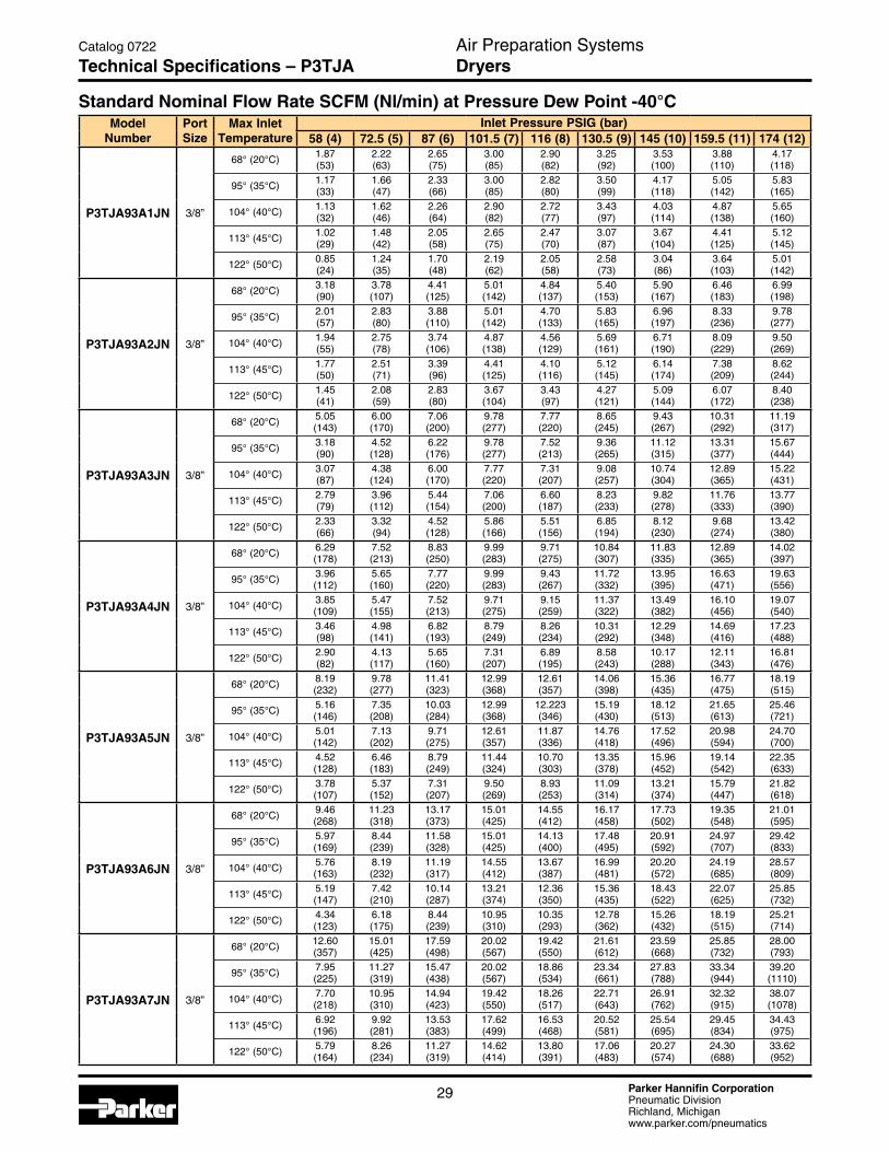
Standard Nominal Flow Rate SCFM (Nl/min) at Pressure Dew Point -40°CModel
NumberPort Size
Max Inlet Temperature
Inlet Pressure PSIG (bar)58 (4) 72.5 (5) 87 (6) 101.5 (7) 116 (8) 130.5 (9) 145 (10) 159.5 (11) 174 (12)
P3TJA93A1JN 3/8”
68° (20°C) 1.87 (53)
2.22(63)
2.65(75)
3.00(85)
2.90(82)
3.25(92)
3.53(100)
3.88(110)
4.17(118)
95° (35°C) 1.17 (33)
1.66(47)
2.33(66)
3.00(85)
2.82(80)
3.50(99)
4.17(118)
5.05(142)
5.83(165)
104° (40°C) 1.13 (32)
1.62(46)
2.26(64)
2.90(82)
2.72(77)
3.43(97)
4.03(114)
4.87(138)
5.65(160)
113° (45°C) 1.02(29)
1.48(42)
2.05(58)
2.65(75)
2.47(70)
3.07(87)
3.67(104)
4.41(125)
5.12(145)
122° (50°C) 0.85(24)
1.24(35)
1.70(48)
2.19(62)
2.05(58)
2.58(73)
3.04(86)
3.64(103)
5.01(142)
P3TJA93A2JN 3/8”
68° (20°C) 3.18(90)
3.78(107)
4.41(125)
5.01(142)
4.84(137)
5.40(153)
5.90(167)
6.46(183)
6.99(198)
95° (35°C) 2.01(57)
2.83(80)
3.88(110)
5.01(142)
4.70(133)
5.83(165)
6.96(197)
8.33(236)
9.78(277)
104° (40°C) 1.94(55)
2.75(78)
3.74(106)
4.87(138)
4.56(129)
5.69(161)
6.71(190)
8.09(229)
9.50(269)
113° (45°C) 1.77(50)
2.51(71)
3.39(96)
4.41(125)
4.10(116)
5.12(145)
6.14(174)
7.38(209)
8.62(244)
122° (50°C) 1.45(41)
2.08(59)
2.83(80)
3.67(104)
3.43(97)
4.27(121)
5.09(144)
6.07(172)
8.40(238)
P3TJA93A3JN 3/8”
68° (20°C) 5.05(143)
6.00(170)
7.06(200)
9.78(277)
7.77(220)
8.65(245)
9.43(267)
10.31(292)
11.19(317)
95° (35°C) 3.18(90)
4.52(128)
6.22(176)
9.78(277)
7.52(213)
9.36(265)
11.12(315)
13.31(377)
15.67(444)
104° (40°C) 3.07(87)
4.38(124)
6.00(170)
7.77(220)
7.31(207)
9.08(257)
10.74(304)
12.89(365)
15.22(431)
113° (45°C) 2.79(79)
3.96(112)
5.44(154)
7.06(200)
6.60(187)
8.23(233)
9.82 (278)
11.76(333)
13.77(390)
122° (50°C) 2.33(66)
3.32(94)
4.52(128)
5.86(166)
5.51(156)
6.85(194)
8.12(230)
9.68(274)
13.42(380)
P3TJA93A4JN 3/8”
68° (20°C) 6.29(178)
7.52(213)
8.83(250)
9.99(283)
9.71(275)
10.84(307)
11.83(335)
12.89(365)
14.02(397)
95° (35°C) 3.96(112)
5.65(160)
7.77(220)
9.99(283)
9.43(267)
11.72(332)
13.95(395)
16.63(471)
19.63(556)
104° (40°C) 3.85(109)
5.47(155)
7.52(213)
9.71(275)
9.15(259)
11.37(322)
13.49(382)
16.10(456)
19.07(540)
113° (45°C) 3.46(98)
4.98(141)
6.82(193)
8.79(249)
8.26(234)
10.31(292)
12.29(348)
14.69(416)
17.23 (488)
122° (50°C) 2.90(82)
4.13(117)
5.65(160)
7.31(207)
6.89(195)
8.58(243)
10.17(288)
12.11(343)
16.81(476)
P3TJA93A5JN 3/8”
68° (20°C) 8.19(232)
9.78(277)
11.41(323)
12.99(368)
12.61(357)
14.06(398)
15.36(435)
16.77(475)
18.19(515)
95° (35°C) 5.16(146)
7.35(208)
10.03(284)
12.99(368)
12.223(346)
15.19(430)
18.12(513)
21.65(613)
25.46(721)
104° (40°C) 5.01(142)
7.13(202)
9.71(275)
12.61(357)
11.87(336)
14.76(418)
17.52(496)
20.98(594)
24.70(700)
113° (45°C) 4.52(128)
6.46(183)
8.79(249)
11.44(324)
10.70(303)
13.35(378)
15.96(452)
19.14(542)
22.35(633)
122° (50°C) 3.78(107)
5.37(152)
7.31(207)
9.50(269)
8.93(253)
11.09(314)
13.21(374)
15.79(447)
21.82(618)
P3TJA93A6JN 3/8”
68° (20°C) 9.46(268)
11.23(318)
13.17(373)
15.01(425)
14.55(412)
16.17(458)
17.73(502)
19.35(548)
21.01(595)
95° (35°C) 5.97(169}
8.44(239)
11.58(328)
15.01(425)
14.13(400)
17.48(495)
20.91(592)
24.97(707)
29.42(833)
104° (40°C) 5.76(163)
8.19(232)
11.19(317)
14.55(412)
13.67(387)
16.99(481)
20.20(572)
24.19(685)
28.57(809)
113° (45°C) 5.19(147)
7.42(210)
10.14(287)
13.21(374)
12.36(350)
15.36(435)
18.43(522)
22.07(625)
25.85(732)
122° (50°C) 4.34(123)
6.18(175)
8.44(239)
10.95(310)
10.35(293)
12.78(362)
15.26(432)
18.19(515)
25.21(714)
P3TJA93A7JN 3/8”
68° (20°C) 12.60(357)
15.01(425)
17.59(498)
20.02(567)
19.42(550)
21.61(612)
23.59(668)
25.85(732)
28.00(793)
95° (35°C) 7.95(225)
11.27(319)
15.47(438)
20.02(567)
18.86(534)
23.34(661)
27.83(788)
33.34(944)
39.20(1110)
104° (40°C) 7.70(218)
10.95(310)
14.94(423)
19.42(550)
18.26(517)
22.71(643)
26.91(762)
32.32(915)
38.07(1078)
113° (45°C) 6.92(196)
9.92(281)
13.53(383)
17.62 (499)
16.53(468)
20.52(581)
25.54(695)
29.45(834)
34.43(975)
122° (50°C) 5.79(164)
8.26(234)
11.27(319)
14.62(414)
13.80(391)
17.06(483)
20.27(574)
24.30(688)
33.62(952)
Catalog 0722
Technical Specifications – P3TJAAir Preparation Systems Dryers
Parker Hannifin CorporationPneumatic DivisionRichland, Michiganwww.parker.com/pneumatics
30
Air Preparation SystemsCatalog 0722
Safety Guide
Safety Guide For Selecting And Using Pneumatic Division Products And Related Accessories
WARNING:FAILURE OR IMPROPER SELECTION OR IMPROPER USE OF PNEUMATIC DIVISION PRODUCTS, ASSEMBLIES OR RELATED ITEMS (“PRODUCTS”) CAN CAUSE DEATH, PERSONAL INJURY, AND PROPERTY DAMAGE. POSSIBLE CONSEQUENCES OF FAILURE OR IMPROPER SELECTION OR IMPROPER USE OF THESE PRODUCTS INCLUDE BUT ARE NOT LIMITED TO:• Unintended or mistimed cycling or motion of machine members or failure to cycle• Work pieces or component parts being thrown off at high speeds.• Failure of a device to function properly for example, failure to clamp or unclamp an associated item or device.• Explosion• Suddenly moving or falling objects.• Release of toxic or otherwise injurious liquids or gasses.Before selecting or using any of these Products, it is important that you read and follow the instructions below.
!
1. GENERAL INSTRUCTIONS 1.1. Scope: This safety guide is designed to cover general guidelines on the installation, use, and maintenance of Pneumatic Division
Valves, FRLs (Filters, Pressure Regulators, and Lubricators), Vacuum products and related accessory components. 1.2. Fail-Safe: Valves, FRLs, Vacuum products and their related components can and do fail without warning for many reasons. Design all
systems and equipment in a fail-safe mode, so that failure of associated valves, FRLs or Vacuum products will not endanger persons or property.
1.3 Relevant International Standards: For a good guide to the application of a broad spectrum of pneumatic fluid power devices see: ISO 4414:1998, Pneumatic Fluid Power – General Rules Relating to Systems. See www.iso.org for ordering information.
1.4. Distribution: Provide a copy of this safety guide to each person that is responsible for selection, installation, or use of Valves, FRLs or Vacuum products. Do not select, or use Parker valves, FRLs or vacuum products without thoroughly reading and understanding this safety guide as well as the specific Parker publications for the products considered or selected.
1.5. User Responsibility: Due to the wide variety of operating conditions and applications for valves, FRLs, and vacuum products Parker and its distributors do not represent or warrant that any particular valve, FRL or vacuum product is suitable for any specific end use system. This safety guide does not analyze all technical parameters that must be considered in selecting a product. The user, through its own analysis and testing, is solely responsible for: • Making the final selection of the appropriate valve, FRL, Vacuum component, or accessory.
• Assuring that all user’s performance, endurance, maintenance, safety, and warning requirements are met and that the application presents no health or safety hazards.
• Complying with all existing warning labels and / or providing all appropriate health and safety warnings on the equipment on which the valves, FRLs or Vacuum products are used; and,
• Assuring compliance with all applicable government and industry standards. 1.6. Safety Devices: Safety devices should not be removed, or defeated. 1.7. Warning Labels: Warning labels should not be removed, painted over or otherwise obscured. 1.8. Additional Questions: Call the appropriate Parker technical service department if you have any questions or require any additional
information. See the Parker publication for the product being considered or used, or call 1-800-CPARKER, or go to www.parker.com, for telephone numbers of the appropriate technical service department.
2. PRODUCT SELECTION INSTRUCTIONS 2.1. Flow Rate: The flow rate requirements of a system are frequently the primary consideration when designing any pneumatic system.
System components need to be able to provide adequate flow and pressure for the desired application. 2.2. Pressure Rating: Never exceed the rated pressure of a product. Consult product labeling, Pneumatic Division catalogs or the
instruction sheets supplied for maximum pressure ratings. 2.3. Temperature Rating: Never exceed the temperature rating of a product. Excessive heat can shorten the life expectancy of a product
and result in complete product failure. 2.4. Environment: Many environmental conditions can affect the integrity and suitability of a product for a given application. Pneumatic
Division products are designed for use in general purpose industrial applications. If these products are to be used in unusual circumstances such as direct sunlight and/or corrosive or caustic environments, such use can shorten the useful life and lead to premature failure of a product.
2.5. Lubrication and Compressor Carryover: Some modern synthetic oils can and will attack nitrile seals. If there is any possibility of synthetic oils or greases migrating into the pneumatic components check for compatibility with the seal materials used. Consult the factory or product literature for materials of construction.
2.6. Polycarbonate Bowls and Sight Glasses: To avoid potential polycarbonate bowl failures: • Do not locate polycarbonate bowls or sight glasses in areas where they could be subject to direct sunlight, impact blow, or temperatures outside of the rated range.
• Do not expose or clean polycarbonate bowls with detergents, chlorinated hydro-carbons, keytones, esters or certain alcohols. • Do not use polycarbonate bowls or sight glasses in air systems where compressors are lubricated with fire resistant fluids such as
phosphate ester and di-ester lubricants.
Parker Hannifin CorporationPneumatic DivisionRichland, Michiganwww.parker.com/pneumatics
31
Air Preparation SystemsCatalog 0722
Safety Guide
2.7. Chemical Compatibility: For more information on plastic component chemical compatibility see Pneumatic Division technical bulletins Tec-3, Tec-4, and Tec-5
2.8. Product Rupture: Product rupture can cause death, serious personal injury, and property damage. • Do not connect pressure regulators or other Pneumatic Division products to bottled gas cylinders.
• Do not exceed the maximum primary pressure rating of any pressure regulator or any system component. • Consult product labeling or product literature for pressure rating limitations.3. PRODUCT ASSEMBLY AND INSTALLATION INSTRUCTIONS 3.1. Component Inspection: Prior to assembly or installation a careful examination of the valves, FRLs or vacuum products must be
performed. All components must be checked for correct style, size, and catalog number. DO NOT use any component that displays any signs of nonconformance.
3.2. Installation Instructions: Parker published Installation Instructions must be followed for installation of Parker valves, FRLs and vacuum components. These instructions are provided with every Parker valve or FRL sold, or by calling 1-800-CPARKER, or at www.parker.com.
3.3. Air Supply: The air supply or control medium supplied to Valves, FRLs and Vacuum components must be moisture-free if ambient temperature can drop below freezing
4. VALVE AND FRL MAINTENANCE AND REPLACEMENT INSTRUCTIONS 4.1. Maintenance: Even with proper selection and installation, valve, FRL and vacuum products service life may be significantly reduced
without a continuing maintenance program. The severity of the application, risk potential from a component failure, and experience with any known failures in the application or in similar applications should determine the frequency of inspections and the servicing or replacement of Pneumatic Division products so that products are replaced before any failure occurs. A maintenance program must be established and followed by the user and, at minimum, must include instructions 4.2 through 4.10.
4.2. Installation and Service Instructions: Before attempting to service or replace any worn or damaged parts consult the appropriate Service Bulletin for the valve or FRL in question for the appropriate practices to service the unit in question. These Service and Installation Instructions are provided with every Parker valve and FRL sold, or are available by calling 1-800-CPARKER, or by accessing the Parker web site at www.parker.com.
4.3. Lockout / Tagout Procedures: Be sure to follow all required lockout and tagout procedures when servicing equipment. For more information see: OSHA Standard – 29 CFR, Part 1910.147, Appendix A, The Control of Hazardous Energy – (Lockout / Tagout)
4.4. Visual Inspection: Any of the following conditions requires immediate system shut down and replacement of worn or damaged components: • Air leakage: Look and listen to see if there are any signs of visual damage to any of the components in the system. Leakage is an indication of worn or damaged components.
• Damaged or degraded components: Look to see if there are any visible signs of wear or component degradation. • Kinked, crushed, or damaged hoses. Kinked hoses can result in restricted air flow and lead to unpredictable system behavior. • Any observed improper system or component function: Immediately shut down the system and correct malfunction. • Excessive dirt build-up: Dirt and clutter can mask potentially hazardous situations. Caution: Leak detection solutions should be rinsed off after use. 4.5. Routine Maintenance Issues:
• Remove excessive dirt, grime and clutter from work areas. • Make sure all required guards and shields are in place. 4.6. Functional Test: Before initiating automatic operation, operate the system manually to make sure all required functions operate
properly and safely. 4.7. Service or Replacement Intervals: It is the user’s responsibility to establish appropriate service intervals. Valves, FRLs and vacuum
products contain components that age, harden, wear, and otherwise deteriorate over time. Environmental conditions can significantly accelerate this process. Valves, FRLs and vacuum components need to be serviced or replaced on routine intervals. Service intervals need to be established based on: • Previous performance experiences.
• Government and / or industrial standards. • When failures could result in unacceptable down time, equipment damage or personal injury risk. 4.8. Servicing or Replacing of any Worn or Damaged Parts: To avoid unpredictable system behavior that can cause death, personal
injury and property damage: • Follow all government, state and local safety and servicing practices prior to service including but not limited to all OSHA Lockout Tagout procedures (OSHA Standard – 29 CFR, Part 1910.147, Appendix A, The Control of Hazardous Energy – Lockout / Tagout).
• Disconnect electrical supply (when necessary) before installation, servicing, or conversion. • Disconnect air supply and depressurize all air lines connected to system and Pneumatic Division products before installation, service,
or conversion. • Installation, servicing, and / or conversion of these products must be performed by knowledgeable personnel who understand how
pneumatic products are to be applied. • After installation, servicing, or conversions air and electrical supplies (when necessary) should be connected and the product tested
for proper function and leakage. If audible leakage is present, or if the product does not operate properly, do not put product or system into use.
• Warnings and specifications on the product should not be covered or painted over. If masking is not possible, contact your local representative for replacement labels.
4.9. Putting Serviced System Back into Operation: Follow the guidelines above and all relevant Installation and Maintenance Instructions supplied with the valve FRL or vacuum component to insure proper function of the system.
Parker Hannifin CorporationPneumatic DivisionRichland, Michiganwww.parker.com/pneumatics
32
The items described in this document and other documents or descriptions provided by Parker Hannifin Corporation, its subsidiaries and its authorized distributors, are hereby offered for sale at prices to be established by Parker Hannifin Corporation, its subsidiaries and its authorized distributors. This offer and its acceptance by any customer (“Buyer”) shall be governed by all of the following Terms and Conditions. Buyer’s order for any such item, when communicated to Parker Hannifin Corporation, its subsidiaries or an authorized distributor (“Seller”) verbally or in writing, shall constitute acceptance of this offer.
1. Terms and Conditions of Sale: All descriptions, quotations, proposals, offers, acknowledgments, acceptances and sales of Seller’s products are subject to and shall be governed exclusively by the terms and conditions stated herein. Buyer’s acceptance of any offer to sell is limited to these terms and conditions. Any terms or conditions in addition to, or inconsistent with those stated herein, proposed by Buyer in any acceptance of an offer by Seller, are hereby objected to. No such additional, different or inconsistent terms and conditions shall become part of the contract between Buyer and Seller unless expressly accepted in writing by Seller. Seller’s acceptance of any offer to purchase by Buyer is expressly conditional upon Buyer’s assent to all the terms and conditions stated herein, including any terms in addition to, or inconsistent with those contained in Buyer’s offer. Acceptance of Seller’s products shall in all events constitute such assent.2. Payment: Payment shall be made by Buyer net 30 days from the date of delivery of the items purchased hereunder. Amounts not timely paid shall bear interest at the maximum rate permitted by law for each month or portion thereof that the Buyer is late in making payment. Any claims by Buyer for omissions or shortages in a shipment shall be waived unless Seller receives notice thereof within 30 days after Buyer’s receipt of the shipment.3. Delivery: Unless otherwise provided on the face hereof, delivery shall be made F.O.B. Seller’s plant. Regardless of the method of delivery, however, risk of loss shall pass to Buyer upon Seller’s delivery to a carrier. Any delivery dates shown are approximate only and Seller shall have no liability for any delays in delivery.4. Warranty: Seller warrants that the items sold hereunder shall be free from defects in material or workmanship for a period of 18 months from date of shipment from Parker Hannifin Corporation. THIS WARRANTY COMPRISES THE SOLE AND ENTIRE WARRANTY PERTAINING TO ITEMS PROVIDED HEREUNDER. SELLER MAKES NO OTHER WARRANTY, GUARANTEE, OR REPRESENTATION OF ANY KIND WHATSOEVER. ALL OTHER WARRANTIES, INCLUDING BUT NOT LIMITED TO, MERCHANTABILITY AND FITNESS FOR PURPOSE, WHETHER EXPRESS, IMPLIED, OR ARISING BY OPERATION OF LAW, TRADE USAGE, OR COURSE OF DEALING ARE HEREBY DISCLAIMED.NOTWITHSTANDING THE FOREGOING, THERE ARE NO WARRANTIES WHATSOEVER ON ITEMS BUILT OR ACQUIRED WHOLLY OR PARTIALLY, TO BUYER’S DESIGN OR SPECIFICATIONS.5. Limitation of Remedy: SELLER’S LIABILITY ARISING FROM OR IN ANY WAY CONNECTED WITH THE ITEMS SOLD OR THIS CONTRACT SHALL BE LIMITED EXCLUSIVELY TO REPAIR OR REPLACEMENT OF THE ITEMS SOLD OR REFUND OF THE PURCHASE PRICE PAID BY BUYER, AT SELLER’S SOLE OPTION. IN NO EVENT SHALL SELLER BE LIABLE FOR ANY INCIDENTAL, CONSEQUENTIAL OR SPECIAL DAMAGES OF ANY KIND OR NATURE WHATSOEVER, INCLUDING BUT NOT LIMITED TO LOST PROFITS ARISING FROM OR IN ANY WAY CONNECTED WITH THIS AGREEMENT OR ITEMS SOLD HEREUNDER, WHETHER ALLEGED TO ARISE FROM BREACH OF CONTRACT, EXPRESS OR IMPLIED WARRANTY, OR IN TORT, INCLUDING WITHOUT LIMITATION, NEGLIGENCE, FAILURE TO WARN OR STRICT LIABILITY.6. Changes, Reschedules and Cancellations: Buyer may request to modify the designs or specifications for the items sold hereunder as well as the quantities and delivery dates thereof, or may request to cancel all or part of this order, however, no such requested modification or cancellation shall become part of the contract between Buyer and Seller unless accepted by Seller in a written amendment to this Agreement. Acceptance of any such requested modification or cancellation shall be at Seller’s discretion, and shall be upon such terms and conditions as Seller may require.7. Special Tooling: A tooling charge may be imposed for any special tooling, including without limitations, dies, fixtures, molds and patterns, acquired to manufacture items sold pursuant to this contract. Such special tooling shall be and remain Seller’s property notwithstanding payment of any charges by Buyer. In no event will Buyer acquire any interest in apparatus belonging to Seller which is utilized in the manufacture of the items sold hereunder, even if such apparatus has been specially converted or adapted for such manufacture and notwithstanding any
charges paid by Buyer. Unless otherwise agreed, Seller shall have the right to alter, discard or otherwise dispose of any special tooling or other property in its sole discretion at any time.8. Buyer’s Property: Any designs, tools, patterns, materials, drawings, confidential information or equipment furnished by Buyer, or any other items which become Buyer’s property, may be considered obsolete and may be destroyed by Seller after two (2) consecutive years have elapsed without Buyer placing an order for the items which are manufactured using such property. Seller shall not be responsible for any loss or damage to such property while it is in Seller’s possession or control.9. Taxes: Unless otherwise indicated on the face hereof, all prices and charges are exclusive of excise, sales, use, property, occupational or like taxes which may be imposed by any taxing authority upon the manufacture, sale or delivery of the items sold hereunder. If any such taxes must be paid by Seller or if Seller is liable for the collection of such tax, the amount thereof shall be in addition to the amounts for the items sold. Buyer agrees to pay all such taxes or to reimburse Seller therefore upon receipt of its invoice. If Buyer claims exemption from any sales, use or other tax imposed by any taxing authority, Buyer shall save Seller harmless from and against any such tax, together with any interest or penalties thereon which may be assessed if the items are held to be taxable.10. Indemnity For Infringement of Intellectual Property Rights: Seller shall have no liability for infringement of any patents, trademarks, copyrights, trade dress, trade secrets or similar rights except as provided in this Part 10. Seller will defend and indemnify Buyer against allegations of infringement of U.S. patents, U.S. trademarks, copyrights, trade dress and trade secrets (hereinafter “Intellectual Property Rights”). Seller will defend at its expense and will pay the cost of any settlement or damages awarded in an action brought against Buyer based on an allegation that an item sold pursuant to this contract infringes the Intellectual Property Rights of a third party. Seller’s obligation to defend and indemnify Buyer is contingent on Buyer notifying Seller within ten (10) days after Buyer becomes aware of such allegations of infringement, and Seller having sole control over the defense of any allegations or actions including all negotiations for settlement or compromise. If an item sold hereunder is subject to a claim that it infringes the Intellectual Property Rights of a third party, Seller may, at its sole expense and option, procure for Buyer the right to continue using said item, replace or modify said item so as to make it noninfringing, or offer to accept return of said item and return the purchase price less a reasonable allowance for depreciation. Notwithstanding the foregoing, Seller shall have no liability for claims of infringement based on information provided by Buyer, or directed to items delivered hereunder for which the designs are specified in whole or part by Buyer, or infringements resulting from the modification, combination or use in a system of any item sold hereunder. The foregoing provisions of this Part 10 shall constitute Seller’s sole and exclusive liability and Buyer’s sole and exclusive remedy for infringement of Intellectual Property Rights.If a claim is based on information provided by Buyer or if the design for an item delivered hereunder is specified in whole or in part by Buyer, Buyer shall defend and indemnify Seller for all costs, expenses or judgements resulting from any claim that such item infringes any patent, trademark, copyright, trade dress, trade secret or any similar right.11. Force Majeure: Seller does not assume the risk of and shall not be liable for delay or failure to perform any of Seller’s obligations by reason of circumstances beyond the reasonable control of Seller (hereinafter “Events of Force Majeure”). Events of Force Majeure shall include without limitation, accidents, acts of God, strikes or labor disputes, acts, laws, rules or regulations of any government or government agency, fires, floods, delays or failures in delivery of carriers or suppliers, shortages of materials and any other cause beyond Seller’s control.12. Entire Agreement/Governing Law: The terms and conditions set forth herein, together with any amendments, modifications and any different terms or conditions expressly accepted by Seller in writing, shall constitute the entire Agreement concerning the items sold, and there are no oral or other representations or agreements which pertain thereto. This Agreement shall be governed in all respects by the law of the State of Ohio. No actions arising out of sale of the items sold hereunder or this Agreement may be brought by either party more than two (2) years after the cause of action accrues.
Air Preparation SystemsCatalog 0722
Offer of Sale


Catalog 0722 06/2008
Applications EngineeringPhone: 877 321 4PDN Option #2E-mail: [email protected] SupportPhone: 877 321 4PDN Option #1E-mail: [email protected] site: www.parker.com/pneumatics
Parker Hannifin CorporationPneumatic Division8676 E. M89P.O. Box 901Richland, MI 49083 USATel: 269 629 5000Fax: 269 629 5385