Embed Size (px)
Citation preview
Evaluates: DS28E17DS28E17 Evaluation System
General DescriptionThe DS28E17 evaluation system (EV system) provides the special hardware and software system to exercise the features of the DS28E17 1-Wire®-to-I2C master bridge IC. The EV system consists of a DS28E17 EV kit board and a DS9481P-300# USB-to-1-Wire adapter for PC connectivity. The EV kit is compatible with Windows® operating systems.
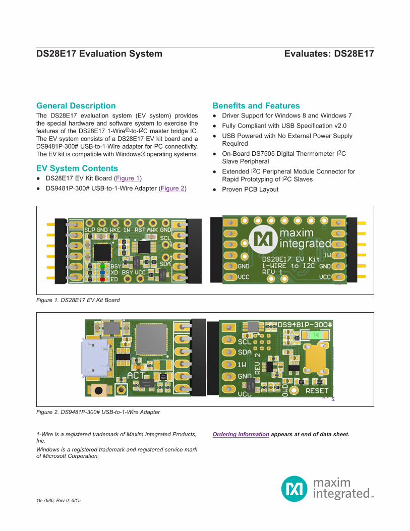
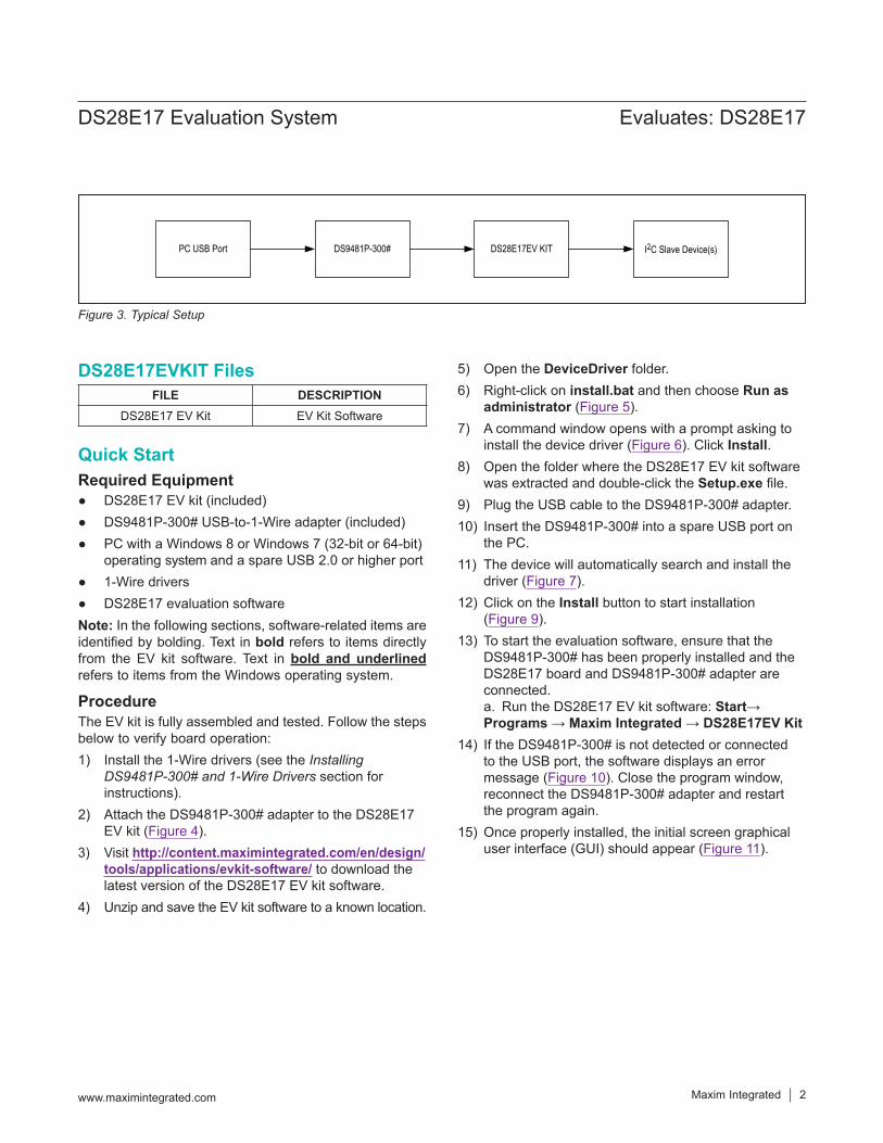
EV System Contents ● DS28E17 EV Kit Board (Figure 1) ● DS9481P-300# USB-to-1-Wire Adapter (Figure 2)
Benefits and Features ● Driver Support for Windows 8 and Windows 7 ● Fully Compliant with USB Specification v2.0 ● USB Powered with No External Power Supply
Required ● On-Board DS7505 Digital Thermometer I2C
Slave Peripheral ● Extended I2C Peripheral Module Connector for
Rapid Prototyping of I2C Slaves ● Proven PCB Layout
19-7686; Rev 0; 6/15
Ordering Information appears at end of data sheet.1-Wire is a registered trademark of Maxim Integrated Products, Inc.Windows is a registered trademark and registered service mark of Microsoft Corporation.
Figure 2. DS9481P-300# USB-to-1-Wire Adapter
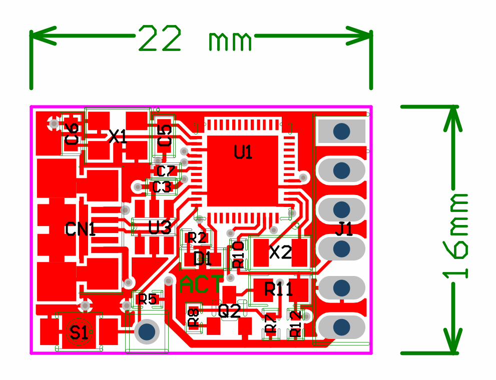
Figure 1. DS28E17 EV Kit Board
Maxim Integrated │ 2www.maximintegrated.com
Evaluates: DS28E17DS28E17 Evaluation System
Quick StartRequired Equipment
● DS28E17 EV kit (included) ● DS9481P-300# USB-to-1-Wire adapter (included) ● PC with a Windows 8 or Windows 7 (32-bit or 64-bit)
operating system and a spare USB 2.0 or higher port ● 1-Wire drivers ● DS28E17 evaluation software
Note: In the following sections, software-related items are identified by bolding. Text in bold refers to items directly from the EV kit software. Text in bold and underlined refers to items from the Windows operating system.
ProcedureThe EV kit is fully assembled and tested. Follow the steps below to verify board operation:1) Install the 1-Wire drivers (see the Installing
DS9481P-300# and 1-Wire Drivers section for instructions).
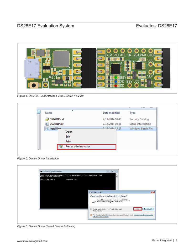
2) Attach the DS9481P-300# adapter to the DS28E17 EV kit (Figure 4).
3) Visit http://content.maximintegrated.com/en/design/tools/applications/evkit-software/ to download the latest version of the DS28E17 EV kit software.
4) Unzip and save the EV kit software to a known location.
5) Open the DeviceDriver folder.6) Right-click on install.bat and then choose Run as
administrator (Figure 5).7) A command window opens with a prompt asking to
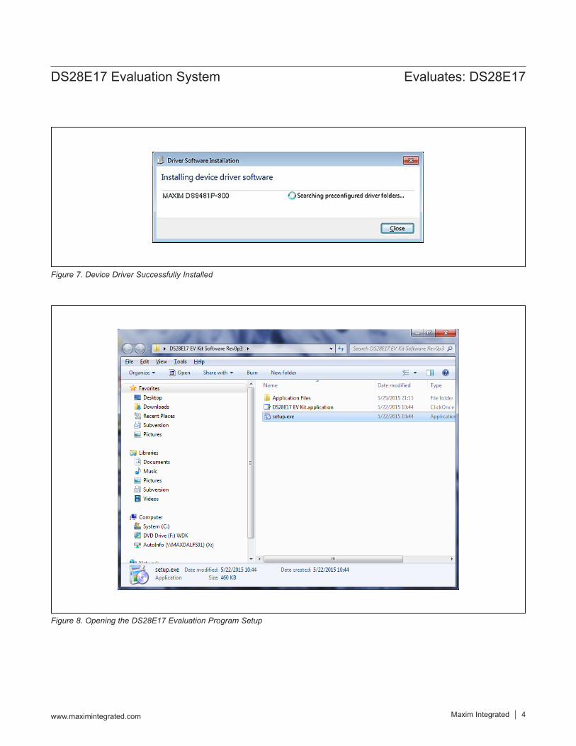
install the device driver (Figure 6). Click Install.8) Open the folder where the DS28E17 EV kit software
was extracted and double-click the Setup.exe file.9) Plug the USB cable to the DS9481P-300# adapter.10) Insert the DS9481P-300# into a spare USB port on
the PC.11) The device will automatically search and install the
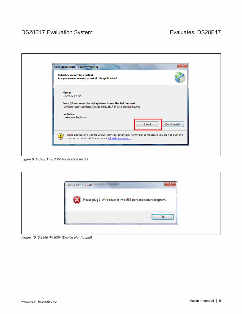
driver (Figure 7).12) Click on the Install button to start installation
(Figure 9).13) To start the evaluation software, ensure that the
DS9481P-300# has been properly installed and the DS28E17 board and DS9481P-300# adapter are connected. a. Run the DS28E17 EV kit software: Start→ Programs → Maxim Integrated → DS28E17EV Kit
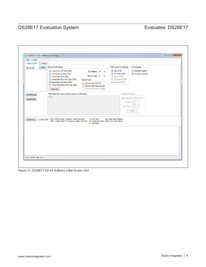
14) If the DS9481P-300# is not detected or connected to the USB port, the software displays an error message (Figure 10). Close the program window, reconnect the DS9481P-300# adapter and restart the program again.
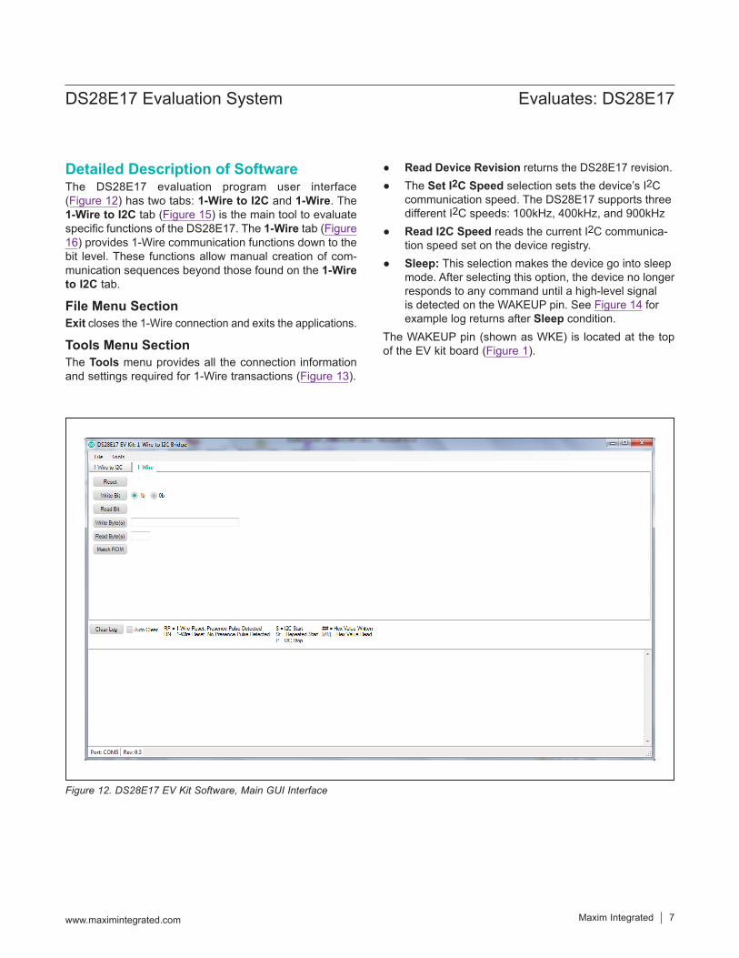
15) Once properly installed, the initial screen graphical user interface (GUI) should appear (Figure 11).
Figure 3. Typical Setup
FILE DESCRIPTIONDS28E17 EV Kit EV Kit Software
PC USB Port DS9481P-300# DS28E17EV KIT I2C Slave Device(s)
DS28E17EVKIT Files
Maxim Integrated │ 3www.maximintegrated.com
Evaluates: DS28E17DS28E17 Evaluation System
Figure 4. DS9481P-300 Attached with DS28E17 EV Kit
Figure 5. Device Driver Installation
Figure 6. Device Driver (Install Device Software)
Maxim Integrated │ 4www.maximintegrated.com
Evaluates: DS28E17DS28E17 Evaluation System
Figure 8. Opening the DS28E17 Evaluation Program Setup
Figure 7. Device Driver Successfully Installed
Maxim Integrated │ 5www.maximintegrated.com
Evaluates: DS28E17DS28E17 Evaluation System
Figure 9. DS28E17 EV Kit Application Install
Figure 10. DS9481P-300# (Device Not Found!)
Maxim Integrated │ 6www.maximintegrated.com
Evaluates: DS28E17DS28E17 Evaluation System
Figure 11. DS28E17 EV Kit Software Initial Screen GUI
Maxim Integrated │ 7www.maximintegrated.com
Evaluates: DS28E17DS28E17 Evaluation System
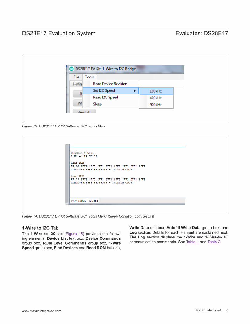
Detailed Description of SoftwareThe DS28E17 evaluation program user interface (Figure 12) has two tabs: 1-Wire to I2C and 1-Wire. The 1-Wire to I2C tab (Figure 15) is the main tool to evaluate specific functions of the DS28E17. The 1-Wire tab (Figure 16) provides 1-Wire communication functions down to the bit level. These functions allow manual creation of com-munication sequences beyond those found on the 1-Wire to I2C tab.
File Menu SectionExit closes the 1-Wire connection and exits the applications.
Tools Menu SectionThe Tools menu provides all the connection information and settings required for 1-Wire transactions (Figure 13).
● Read Device Revision returns the DS28E17 revision. ● The Set I2C Speed selection sets the device’s I2C
communication speed. The DS28E17 supports three different I2C speeds: 100kHz, 400kHz, and 900kHz
● Read I2C Speed reads the current I2C communica-tion speed set on the device registry.
● Sleep: This selection makes the device go into sleep mode. After selecting this option, the device no longer responds to any command until a high-level signal is detected on the WAKEUP pin. See Figure 14 for example log returns after Sleep condition.
The WAKEUP pin (shown as WKE) is located at the top of the EV kit board (Figure 1).
Figure 12. DS28E17 EV Kit Software, Main GUI Interface
Maxim Integrated │ 8www.maximintegrated.com
Evaluates: DS28E17DS28E17 Evaluation System
1-Wire to I2C TabThe 1-Wire to I2C tab (Figure 15) provides the follow-ing elements: Device List text box, Device Commands group box, ROM Level Commands group box, 1-Wire Speed group box, Find Devices and Read ROM buttons,
Write Data edit box, Autofill Write Data group box, and Log section. Details for each element are explained next. The Log section displays the 1-Wire and 1-Wire-to-I2C communication commands. See Table 1 and Table 2.
Figure 13. DS28E17 EV Kit Software GUI, Tools Menu
Figure 14. DS28E17 EV Kit Software GUI, Tools Menu (Sleep Condition Log Results)
Maxim Integrated │ 9www.maximintegrated.com
Evaluates: DS28E17DS28E17 Evaluation System
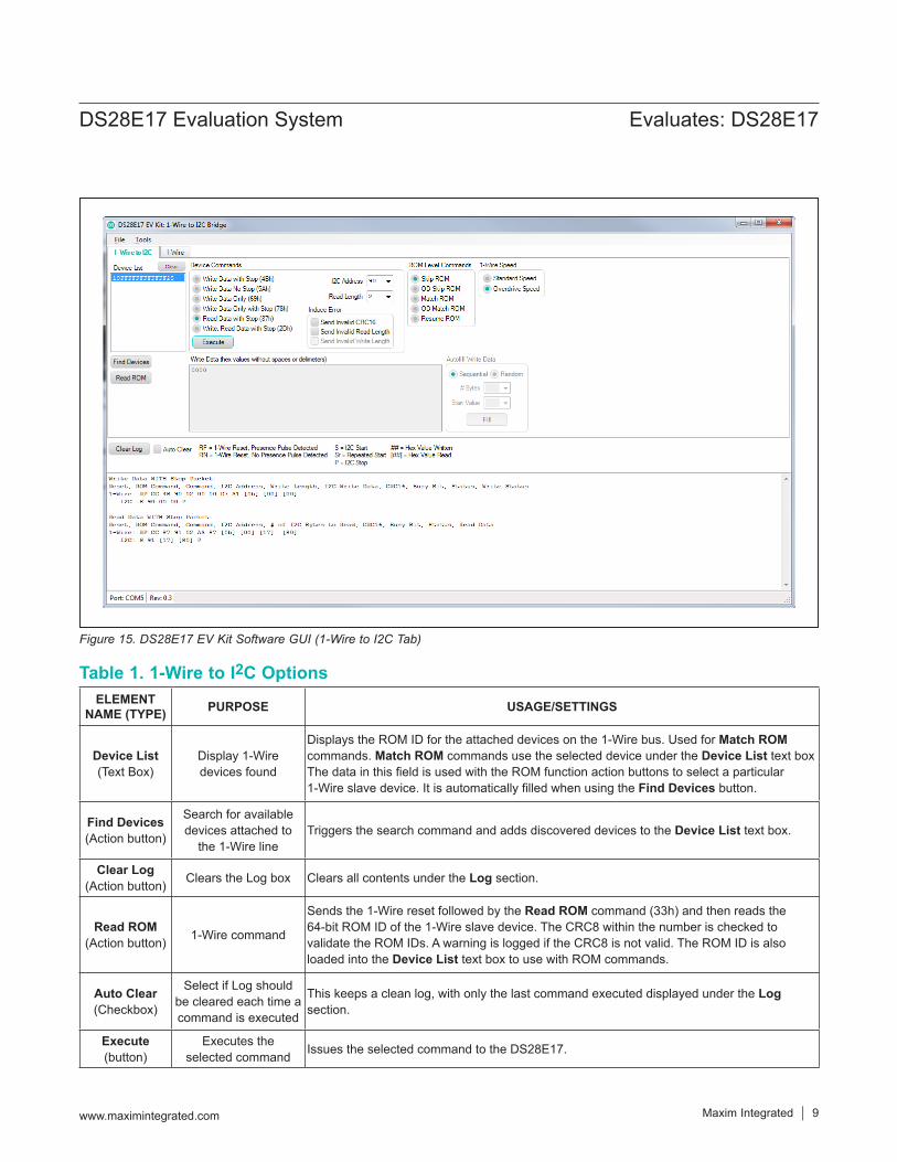
Figure 15. DS28E17 EV Kit Software GUI (1-Wire to I2C Tab)
Table 1. 1-Wire to I2C OptionsELEMENT
NAME (TYPE) PURPOSE USAGE/SETTINGS
Device List(Text Box)
Display 1-Wiredevices found
Displays the ROM ID for the attached devices on the 1-Wire bus. Used for Match ROM commands. Match ROM commands use the selected device under the Device List text box The data in this field is used with the ROM function action buttons to select a particular 1-Wire slave device. It is automatically filled when using the Find Devices button.
Find Devices(Action button)
Search for available devices attached to
the 1-Wire lineTriggers the search command and adds discovered devices to the Device List text box.
Clear Log(Action button) Clears the Log box Clears all contents under the Log section.
Read ROM(Action button) 1-Wire command
Sends the 1-Wire reset followed by the Read ROM command (33h) and then reads the 64-bit ROM ID of the 1-Wire slave device. The CRC8 within the number is checked to validate the ROM IDs. A warning is logged if the CRC8 is not valid. The ROM ID is also loaded into the Device List text box to use with ROM commands.
Auto Clear(Checkbox)
Select if Log should be cleared each time a command is executed
This keeps a clean log, with only the last command executed displayed under the Log section.
Execute(button)
Executes the selected command Issues the selected command to the DS28E17.
Maxim Integrated │ 10www.maximintegrated.com
Evaluates: DS28E17DS28E17 Evaluation System
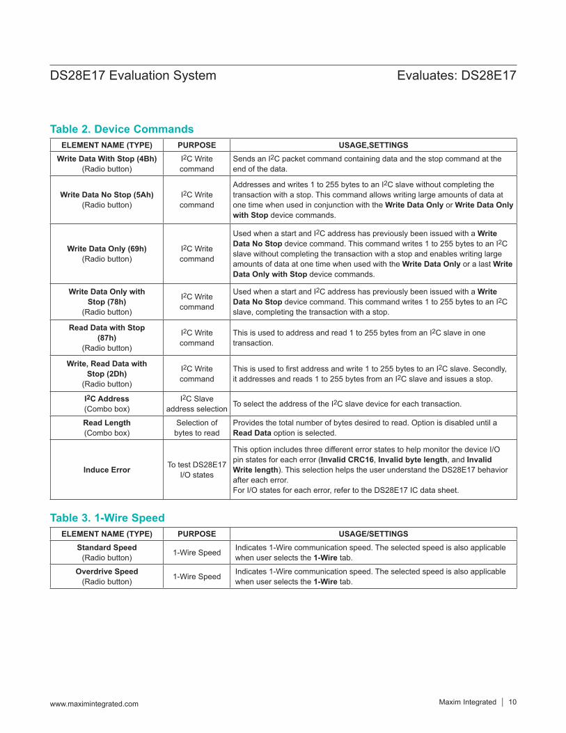
Table 2. Device Commands
Table 3. 1-Wire Speed
ELEMENT NAME (TYPE) PURPOSE USAGE,SETTINGSWrite Data With Stop (4Bh)
(Radio button)I2C Write command
Sends an I2C packet command containing data and the stop command at the end of the data.
Write Data No Stop (5Ah) (Radio button)
I2C Write command
Addresses and writes 1 to 255 bytes to an I2C slave without completing the transaction with a stop. This command allows writing large amounts of data at one time when used in conjunction with the Write Data Only or Write Data Only with Stop device commands.
Write Data Only (69h) (Radio button)
I2C Write command
Used when a start and I2C address has previously been issued with a Write Data No Stop device command. This command writes 1 to 255 bytes to an I2C slave without completing the transaction with a stop and enables writing large amounts of data at one time when used with the Write Data Only or a last Write Data Only with Stop device commands.
Write Data Only with Stop (78h)
(Radio button)
I2C Write command
Used when a start and I2C address has previously been issued with a Write Data No Stop device command. This command writes 1 to 255 bytes to an I2C slave, completing the transaction with a stop.
Read Data with Stop (87h)
(Radio button)
I2C Write command
This is used to address and read 1 to 255 bytes from an I2C slave in one transaction.
Write, Read Data with Stop (2Dh)
(Radio button)
I2C Write command
This is used to first address and write 1 to 255 bytes to an I2C slave. Secondly, it addresses and reads 1 to 255 bytes from an I2C slave and issues a stop.
I2C Address (Combo box)
I2C Slave address selection To select the address of the I2C slave device for each transaction.
Read Length (Combo box)
Selection of bytes to read
Provides the total number of bytes desired to read. Option is disabled until a Read Data option is selected.
Induce Error To test DS28E17 I/O states
This option includes three different error states to help monitor the device I/O pin states for each error (Invalid CRC16, Invalid byte length, and Invalid Write length). This selection helps the user understand the DS28E17 behavior after each error.For I/O states for each error, refer to the DS28E17 IC data sheet.
ELEMENT NAME (TYPE) PURPOSE USAGE/SETTINGSStandard Speed
(Radio button) 1-Wire Speed Indicates 1-Wire communication speed. The selected speed is also applicable when user selects the 1-Wire tab.
Overdrive Speed(Radio button) 1-Wire Speed Indicates 1-Wire communication speed. The selected speed is also applicable
when user selects the 1-Wire tab.
Maxim Integrated │ 11www.maximintegrated.com
Evaluates: DS28E17DS28E17 Evaluation System
1-Wire TabThe 1-Wire tab (Figure 16) provides the low-level 1-Wire primitives that can be used to construct any 1-Wire communication sequence. Choices made in the 1-Wire Speed group box under the 1-Wire to I2C tab (Standard
Speed and Overdrive Speed only) also apply to ROM-level functions. The ROM Level section has functions that implement the 1-Wire ROM function commands, which use the 64-bit ROM ID selected under the Device List in the 1-Wire to I2C tab.
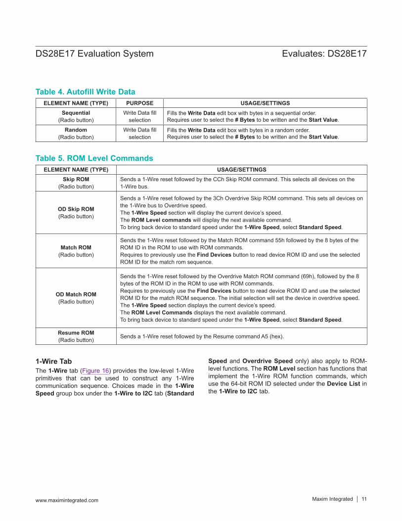
Table 5. ROM Level Commands
Table 4. Autofill Write Data
ELEMENT NAME (TYPE) USAGE/SETTINGSSkip ROM
(Radio button)Sends a 1-Wire reset followed by the CCh Skip ROM command. This selects all devices on the 1-Wire bus.
OD Skip ROM(Radio button)
Sends a 1-Wire reset followed by the 3Ch Overdrive Skip ROM command. This sets all devices on the 1-Wire bus to Overdrive speed.The 1-Wire Speed section will display the current device’s speed.The ROM Level commands will display the next available command.To bring back device to standard speed under the 1-Wire Speed, select Standard Speed.
Match ROM(Radio button)
Sends the 1-Wire reset followed by the Match ROM command 55h followed by the 8 bytes of the ROM ID in the ROM to use with ROM commands.Requires to previously use the Find Devices button to read device ROM ID and use the selected ROM ID for the match rom sequence.
OD Match ROM(Radio button)
Sends the 1-Wire reset followed by the Overdrive Match ROM command (69h), followed by the 8 bytes of the ROM ID in the ROM to use with ROM commands.Requires to previously use the Find Devices button to read device ROM ID and use the selected ROM ID for the match ROM sequence. The initial selection will set the device in overdrive speed. The 1-Wire Speed section displays the current device’s speed.The ROM Level Commands displays the next available command.To bring back device to standard speed under the 1-Wire Speed, select Standard Speed.
Resume ROM(Radio button) Sends a 1-Wire reset followed by the Resume command A5 (hex).
ELEMENT NAME (TYPE) PURPOSE USAGE/SETTINGSSequential
(Radio button)Write Data fill
selectionFills the Write Data edit box with bytes in a sequential order.Requires user to select the # Bytes to be written and the Start Value.
Random (Radio button)
Write Data fill selection
Fills the Write Data edit box with bytes in a random order.Requires user to select the # Bytes to be written and the Start Value.
Maxim Integrated │ 12www.maximintegrated.com
Evaluates: DS28E17DS28E17 Evaluation System
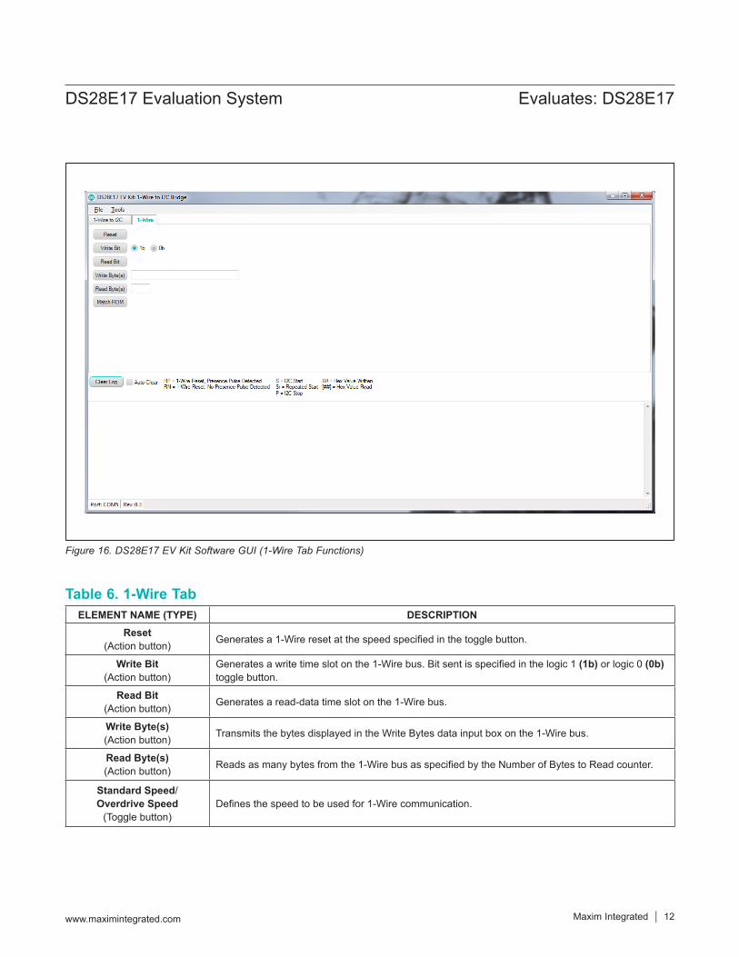
Table 6. 1-Wire Tab
Figure 16. DS28E17 EV Kit Software GUI (1-Wire Tab Functions)
ELEMENT NAME (TYPE) DESCRIPTIONReset
(Action button) Generates a 1-Wire reset at the speed specified in the toggle button.
Write Bit(Action button)
Generates a write time slot on the 1-Wire bus. Bit sent is specified in the logic 1 (1b) or logic 0 (0b) toggle button.
Read Bit(Action button) Generates a read-data time slot on the 1-Wire bus.
Write Byte(s)(Action button) Transmits the bytes displayed in the Write Bytes data input box on the 1-Wire bus.
Read Byte(s)(Action button) Reads as many bytes from the 1-Wire bus as specified by the Number of Bytes to Read counter.
Standard Speed/ Overdrive Speed
(Toggle button)Defines the speed to be used for 1-Wire communication.
Maxim Integrated │ 13www.maximintegrated.com
Evaluates: DS28E17DS28E17 Evaluation System
DS7505 I2C Temperature Sensor ExampleThe EV kit board includes a DS7505 I2C sensor for demo purposes. Additional I2C devices can also be attached to the end of the DS28E17 board.The DS7505 IC data sheet is available for download at www.maximintegrated.com.
Reading Temperature from DS505Follow the steps below to read temperature from the DS505:1) Click the Find Devices button.2) In the Device Commands group box, click the Write
Data with Stop (4Bh) radio button.3) In the I2C Address combo box, type or select 90 to
set the I2C slave address to 90h.4) Inside the Write Data edit box, type 0000.5) Click the Execute button.6) The Log section will display the 1-Wire and I2C
transaction.7) In the Device Commands group box, click the Read
Data with Stop (87h) radio button.
8) The Read Length combo box is enabled.9) Type or select 2 to set the read length to 2 bytes. 10) For more information regarding temperature
readings, refer to the Operation—Measuring Temperature section in the DS2705 IC data sheet.
Temperature Readings Results ● Four bytes are returned on the 1-Wire line. These
bytes represent the Status byte, Write Status, and two I2C bytes from the device. Refer to the DS28E17 IC data sheet for more details.
● The two I2C bytes received ([17] [80]) denote the device temperature, 23.5°C (see Figure 15).
● The DS7505 power-up default is configured for 9-bit resolution.
● 1780h in binary represents 0001 0111 1000 0000. Following Figure 17, the temperature can be calculated.
The DS7505 IC data sheet provides exact temperature calculation procedures and device-specific operation.Other I2C devices can be read using the extension port on the DS28E17 EV kit boards. See Figure 1 for pin selection.
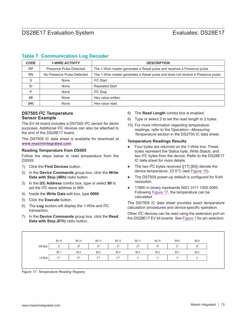
Table 7. Communication Log Decoder
Figure 17. Temperature Reading Registry
Bit 15
SMS Byte
LS Byte
Bit 7
2-1
Bit 14
26
Bit 6
2-2
Bit 13
25
Bit 5
2-3
Bit 12
24
Bit 4
2-4
Bit 11
23
Bit 3
0
Bit 10
22
Bit 2
0
Bit 9
21
Bit 1
0
Bit 8
20
Bit 0
0
CODE 1-WIRE ACTIVITY DESCRIPTIONRP Presence Pulse Detected The 1-Wire master generates a Reset pulse and receives a Presence pulse.
RN No Presence Pulse Detected The 1-Wire master generates a Reset pulse and does not receive a Presence pulse.
S None I2C Start
Sr None Repeated Start
P None I2C Stop
## None Hex value written
[##] None Hex value read
Maxim Integrated │ 14www.maximintegrated.com
Evaluates: DS28E17DS28E17 Evaluation System
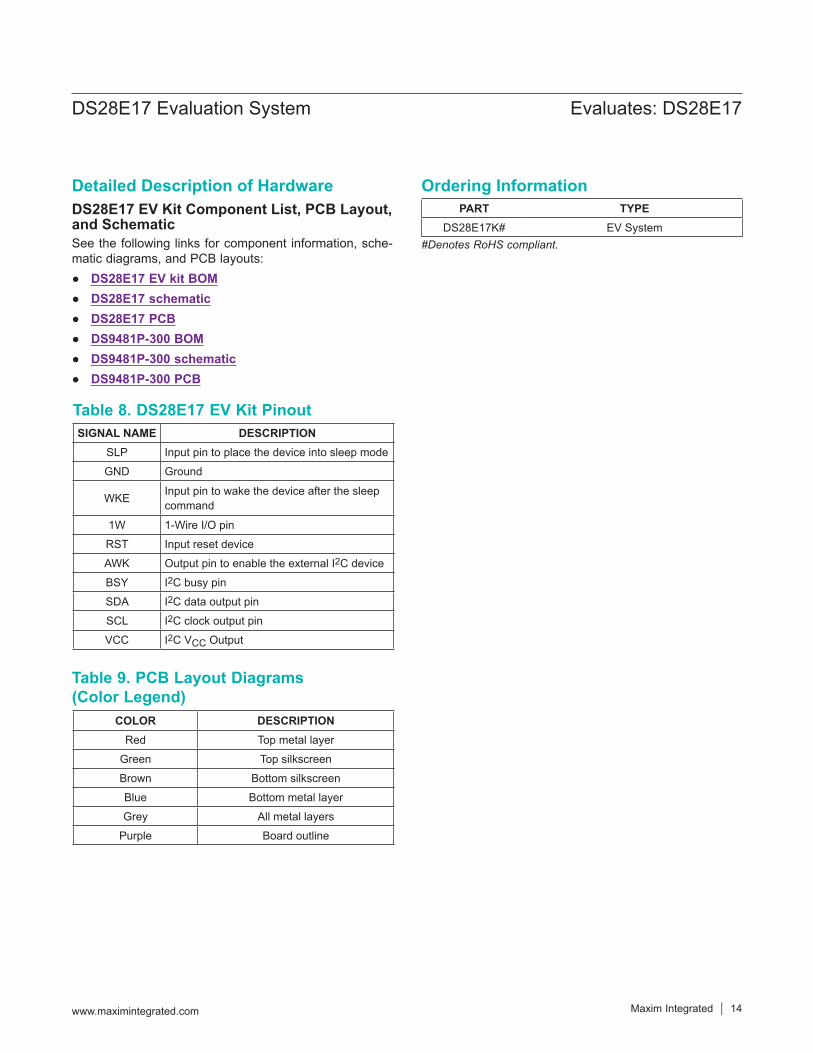
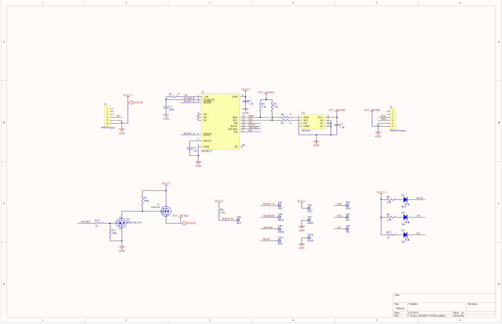
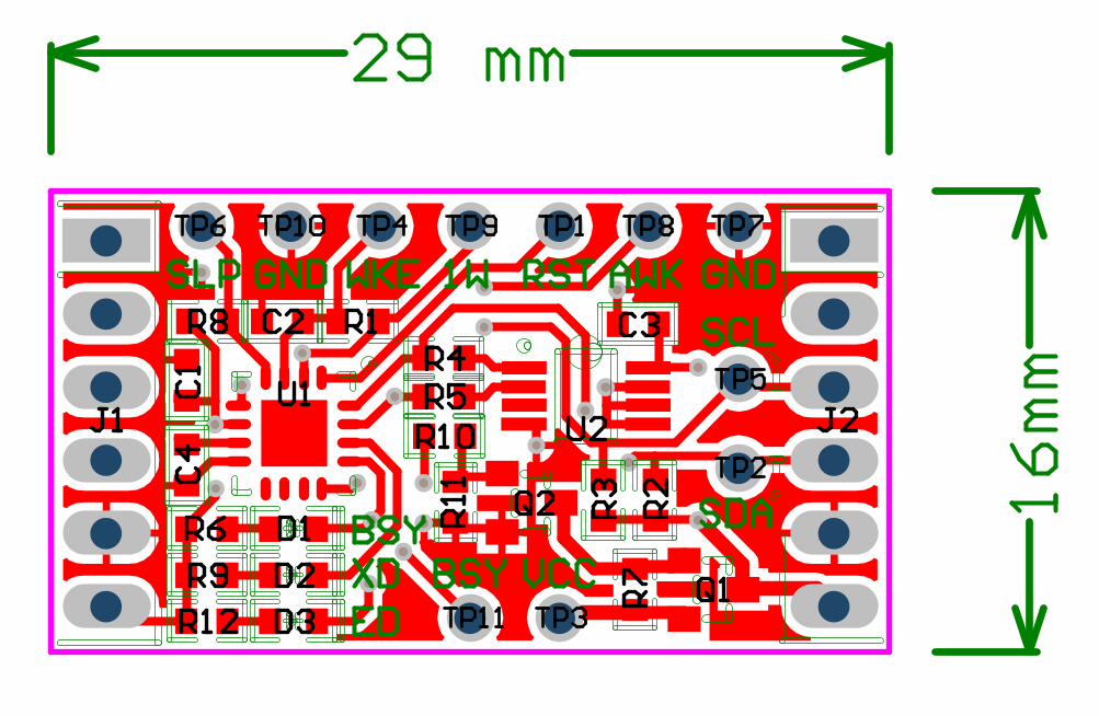
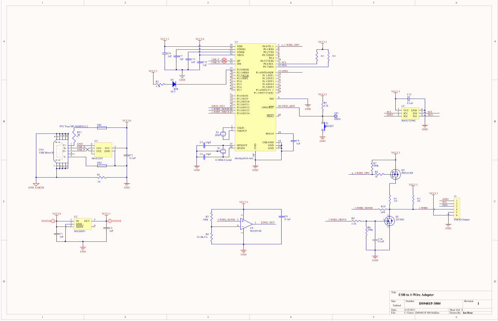
Detailed Description of HardwareDS28E17 EV Kit Component List, PCB Layout, and SchematicSee the following links for component information, sche-matic diagrams, and PCB layouts:
● DS28E17 EV kit BOM ● DS28E17 schematic ● DS28E17 PCB ● DS9481P-300 BOM ● DS9481P-300 schematic ● DS9481P-300 PCB
Table 8. DS28E17 EV Kit Pinout
Table 9. PCB Layout Diagrams (Color Legend)
SIGNAL NAME DESCRIPTIONSLP Input pin to place the device into sleep mode
GND Ground
WKE Input pin to wake the device after the sleep command
1W 1-Wire I/O pin
RST Input reset device
AWK Output pin to enable the external I2C device
BSY I2C busy pin
SDA I2C data output pin
SCL I2C clock output pin
VCC I2C VCC Output
COLOR DESCRIPTIONRed Top metal layer
Green Top silkscreen
Brown Bottom silkscreen
Blue Bottom metal layer
Grey All metal layers
Purple Board outline
#Denotes RoHS compliant.
Ordering InformationPART TYPE
DS28E17K# EV System
Maxim Integrated │ 15www.maximintegrated.com
Evaluates: DS28E17DS28E17 Evaluation System
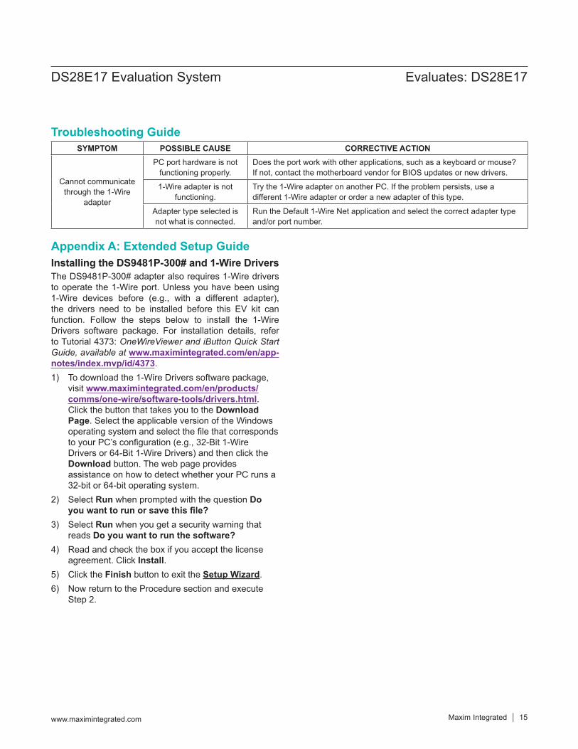
Appendix A: Extended Setup GuideInstalling the DS9481P-300# and 1-Wire DriversThe DS9481P-300# adapter also requires 1-Wire drivers to operate the 1-Wire port. Unless you have been using 1-Wire devices before (e.g., with a different adapter), the drivers need to be installed before this EV kit can function. Follow the steps below to install the 1-Wire Drivers software package. For installation details, refer to Tutorial 4373: OneWireViewer and iButton Quick Start Guide, available at www.maximintegrated.com/en/app-notes/index.mvp/id/4373.1) To download the 1-Wire Drivers software package,
visit www.maximintegrated.com/en/products/comms/one-wire/software-tools/drivers.html. Click the button that takes you to the Download Page. Select the applicable version of the Windows operating system and select the file that corresponds to your PC’s configuration (e.g., 32-Bit 1-Wire Drivers or 64-Bit 1-Wire Drivers) and then click the Download button. The web page provides assistance on how to detect whether your PC runs a 32-bit or 64-bit operating system.
2) Select Run when prompted with the question Do you want to run or save this file?
3) Select Run when you get a security warning that reads Do you want to run the software?
4) Read and check the box if you accept the license agreement. Click Install.
5) Click the Finish button to exit the Setup Wizard.6) Now return to the Procedure section and execute
Step 2.
Troubleshooting GuideSYMPTOM POSSIBLE CAUSE CORRECTIVE ACTION
Cannot communicate through the 1-Wire
adapter
PC port hardware is not functioning properly.
Does the port work with other applications, such as a keyboard or mouse? If not, contact the motherboard vendor for BIOS updates or new drivers.
1-Wire adapter is not functioning.
Try the 1-Wire adapter on another PC. If the problem persists, use a different 1-Wire adapter or order a new adapter of this type.
Adapter type selected is not what is connected.
Run the Default 1-Wire Net application and select the correct adapter type and/or port number.
Maxim Integrated cannot assume responsibility for use of any circuitry other than circuitry entirely embodied in a Maxim Integrated product. No circuit patent licenses are implied. Maxim Integrated reserves the right to change the circuitry and specifications without notice at any time.
Maxim Integrated and the Maxim Integrated logo are trademarks of Maxim Integrated Products, Inc. © 2015 Maxim Integrated Products, Inc. │ 16
Evaluates: DS28E17DS28E17 Evaluation System
Revision HistoryREVISIONNUMBER
REVISIONDATE DESCRIPTION PAGES
CHANGED
0 6/15 Initial release —
For pricing, delivery, and ordering information, please contact Maxim Direct at 1-888-629-4642, or visit Maxim Integrated’s website at www.maximintegrated.com.
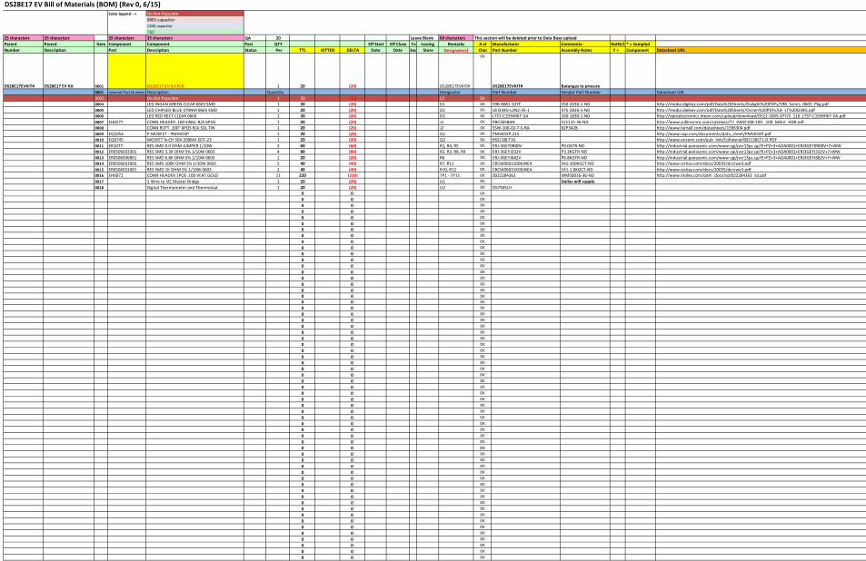
Color legend --> Do Not Populate0805 capacitor 1206 capacitorTBD
25 characters 35 characters 35 characters 35 characters QA 20 Leave Blank 60 characters This section will be deleted prior to Data Base uploadParent Parent Item Component Component Part QTY Eff Start Eff Close To Issuing Remarks # of Manufacturer Comments- RoHS/L * = SampledNumber Description Part Description Status Per TTL KITTED DELTA Date
Date
Seq Store
Designators) Char Part Number Assembly Notes Y = Component Datasheet URL
DS28E17EVKIT# DS28E17 EV Kit 0001 DS28E17 EV Kit PCB 1 20 (20) DS28E17EVKIT#
OK
DS28E17EVKIT# Batangas to procure0001 Internal Part Number Description Quantity Designator Part Number Vendor Part Number Datasheet URL0003 Do Not Populate 1 20 (20) C2 OK 0004 LED INGAN GREEN CLEAR 0603 SMD 1 20 (20) D1 OK 598-8081-107F 350-2036-1-ND http://media.digikey.com/pdf/Data%20Sheets/Dialight%20PDFs/598_Series_0603_Pkg.pdf0005 LED CHIPLED BLUE 470NM 0603 SMD 1 20 (20) D2 OK LB Q39G-L2N2-35-1 475-2816-1-ND http://media.digikey.com/pdf/Data%20Sheets/Osram%20PDFs/LB_LT%20Q39G.pdf0006 LED RED RECT CLEAR 0603 1 20 (20) D3 OK LTST-C193KRKT-5A 160-1830-1-ND http://optoelectronics.liteon.com/upload/download/DS22-2005-077/S_110_LTST-C193KRKT-5A.pdf0007 EH0277 CONN HEADER .100 SINGL R/A 6POS 1 20 (20) J1 OK PBC36SBAN S1111E-36-ND http://www.sullinscorp.com/catalogs/77_PAGE108-109_.100_MALE_HDR.pdf0008 CONN RCPT .100" 6POS R/A SGL TIN 1 20 (20) J2 OK SSW-106-02-T-S-RA 82P3428 http://www.farnell.com/datasheets/1596304.pdf0009 EQ1054 P-MOSFET - PMV65XP 1 20 (20) Q1 OK PMV65XP,215 http://www.nxp.com/documents/data_sheet/PMV65XP.pdf0010 EQ0745 MOSFET N-CH 50V 200MA SOT-23 1 20 (20) Q2 OK BSS138LT1G http://www.onsemi.com/pub_link/Collateral/BSS138LT1-D.PDF0011 ER1077 RES SMD 0.0 OHM JUMPER 1/10W 3 60 (60) R1, R4, R5 OK ERJ-3GEY0R00V P0.0GTR-ND http://industrial.panasonic.com/www-cgi/jvcr13pz.cgi?E+PZ+3+AOA0001+ERJ3GEY0R00V+7+WW0012 ER0506033301 RES SMD 3.3K OHM 5% 1/10W 0603 4 80 (80) R2, R3, R8, R9 OK ERJ-3GEYJ332V P3.3KGTR-ND http://industrial.panasonic.com/www-cgi/jvcr13pz.cgi?E+PZ+3+AOA0001+ERJ3GEYJ332V+7+WW0013 ER0506036801 RES SMD 6.8K OHM 5% 1/10W 0603 1 20 (20) R6 OK ERJ-3GEYJ682V P6.8KGTR-ND http://industrial.panasonic.com/www-cgi/jvcr13pz.cgi?E+PZ+3+AOA0001+ERJ3GEYJ682V+7+WW0014 ER0506031003 RES SMD 100K OHM 5% 1/10W 0603 2 40 (40) R7, R11 OK CRCW0603100KJNEA 541-100KGCT-ND http://www.vishay.com/docs/20035/dcrcwe3.pdf0015 ER0506031001 RES SMD 1K OHM 5% 1/10W 0603 2 40 (40) R10, R12 OK CRCW06031K00JNEA 541-1.0KGCT-ND http://www.vishay.com/docs/20035/dcrcwe3.pdf0016 EH0072 CONN HEADER 1POS .100 VERT GOLD 11 220 (220) TP1 - TP11 OK 0022284363 WM50016-36-ND http://www.molex.com/pdm_docs/sd/022284363_sd.pdf0017 1-Wire to I2C Master Bridge 1 20 (20) U1 OK Dallas will supply 0018 Digital Thermometer and Thermostat 1 20 (20) U2 OK DS7505U+
0 0 OK 0 0 OK 0 0 OK 0 0 OK 0 0 OK 0 0 OK 0 0 OK 0 0 OK 0 0 OK 0 0 OK 0 0 OK 0 0 OK 0 0 OK 0 0 OK 0 0 OK 0 0 OK 0 0 OK 0 0 OK 0 0 OK 0 0 OK 0 0 OK 0 0 OK 0 0 OK 0 0 OK 0 0 OK 0 0 OK 0 0 OK 0 0 OK 0 0 OK 0 0 OK 0 0 OK 0 0 OK 0 0 OK 0 0 OK 0 0 OK 0 0 OK 0 0 OK 0 0 OK 0 0 OK 0 0 OK 0 0 OK 0 0 OK 0 0 OK 0 0 OK 0 0 OK 0 0 OK 0 0 OK 0 0 OK 0 0 OK 0 0 OK
0 0 OK 0 0 OK 0 0 OK 0 0 OK 0 0 OK 0 0 OK0 0 OK 0 0 OK0 0 OK 0 0 OK 0 0 OK
DS28E17 EV Bill of Materials (BOM) (Rev 0, 6/15)
1
1
2
2
3
3
4
4
5
5
6
6
D D
C C
B B
A A
Title
Number RevisionSize
Tabloid
Date: 5/22/2015 Sheet ofFile: C:\Users\..\DS28E17-EVKit.SchDoc Drawn By:
SDA1
SCL2
OS3
GND4 A2 5A1 6A0 7VCC 8U2
DS7505
C31 uF
GND
C11 uF
GND
GND
VCC3.3
C41 uF
R23.3k
R33.3k
R4 0
R5 0
R6
6.8k
R9
3.3k
R12
1k
VCC3.3
BUSY
XD
ED
BUSYXD
ED
TP3
VCC
SDASCL
1W
TP7
GND
TP2
SDA
TP5
SCL
TP9
1WGND
VCC3.3SDA
SCL
1W
VCC3.3 TP1
RST
WAKEUPSLEEP_N
R83.3k
RESET_N
RESET_N
TP6
SLP
SLEEP_N
C2DNP
R1 0
GND
123456
J1
PMOD Input
1W
VCC3.3
GND
SCLSDA
GND
TP4
WKE
WAKEUP
TP10
GND
GND
TP8
AWK
AWAKE
AWAKE
S
D
G
Q1PMV65XP
D
S
G1
23
Q2BSS138LT1G
R10
1k
VCC3.3
GND
AWAKE
R11100k
VCC_AWAKE
VCC_AWAKE
VCC_AWAKE
R7100k
VCC_AWAKE
D3
ED
D2
XD
D1
BSY
1W2
WAKEUP3
SLEEP4
ED 5AWAKE 12
NC9
NC10
NC11
BUSY 13XD 14SCL 15SDA 16
REG187
RESET1
VDD 6
GND8 EP EP
U1
DS28E17
i POWER
i POWER
TP11
BSY
BUSY
123456
J2
PMOD Output
PIC101
PIC102COC1
PIC201
PIC202COC2
PIC301
PIC302COC3
PIC401
PIC402COC4
PID101PID102
COD1
PID201PID202
COD2
PID301PID302
COD3
PIJ101
PIJ102
PIJ103
PIJ104
PIJ105
PIJ106
COJ1
PIJ201
PIJ202
PIJ203
PIJ204
PIJ205
PIJ206
COJ2
PIQ101
PIQ102
PIQ103
COQ1
PIQ201
PIQ202
PIQ203COQ2
PIR101 PIR102
COR1
PIR201
PIR202COR2
PIR301
PIR302COR3
PIR401PIR402
COR4
PIR501PIR502
COR5
PIR601PIR602
COR6
PIR701
PIR702COR7
PIR801
PIR802
COR8
PIR901PIR902COR9
PIR1001 PIR1002
COR10
PIR1101
PIR1102COR11
PIR1201PIR1202
COR12
PITP101
COTP1PITP201
COTP2
PITP301
COTP3
PITP401
COTP4PITP501
COTP5
PITP601
COTP6PITP701
COTP7
PITP801
COTP8PITP901
COTP9
PITP1001
COTP10
PITP1101COTP11
PIU101
PIU102
PIU103
PIU104
PIU105
PIU106
PIU107
PIU108
PIU109
PIU1010
PIU1011
PIU1012
PIU1013
PIU1014
PIU1015
PIU1016
PIU10EP
COU1
PIU201
PIU202
PIU203
PIU204 PIU205
PIU206
PIU207
PIU208
COU2
PIJ104
PIR102
PITP901
PIU102
NL1W
PIR1001
PITP801
PIU1012
NLAWAKE
PID101
PITP1101
PIU1013NLBUSY
PID301
PIU105NLED
PIC101
PIC201
PIC301
PIC401
PIJ105
PIJ205
PIQ202
PIR1101
PITP701
PITP1001
PIU108
PIU204 PIU205
PIU206
PIU207
PIU203
PIU10EP
PIU1011
PIU1010
PIU109
PIR501 PIU202
PIR401 PIU201
PIQ201PIR1002
PIR1102
PIQ101
PIQ203
PIR701
PIJ202
PIJ201
PIJ103
PIJ102
PIJ101
PID302PIR1201
PID202PIR901
PID102PIR601
PIC402PIU107
PITP101
PIU101NLRESET0N
PIJ203
PIR301
PIR502
PITP501
PIU1015NLSCL
PIJ204
PIR201PIR402
PITP201
PIU1016NLSDA
PIR802PITP601
PIU104NLSLEEP0N
PIC102
PIJ106
PIQ102PIR602
PIR702
PIR801
PIR902
PIR1202
PITP301
PIU106
PIC302PIJ206
PIQ103
PIR202 PIR302
PIU208
PIC202
PIR101
PITP401
PIU103NLWAKEUP
PID201
PIU1014NLXD
PAC102
PAC101
COC1PAC202PAC201
COC2PAC302PAC301
COC3
PAC402
PAC401
COC4
PAD102 PAD101
COD1
PAD201PAD202
COD2
PAD301PAD302
COD3
PAJ101
PAJ102
PAJ103
PAJ104
PAJ105
PAJ106COJ1
PAJ201
PAJ202
PAJ203
PAJ204
PAJ205
PAJ206COJ2PAQ103
PAQ101
PAQ102
COQ1PAQ203PAQ201
PAQ202
COQ2
PAR102PAR101
COR1
PAR202
PAR201
COR2
PAR302
PAR301
COR3PAR402 PAR401
COR4
PAR502 PAR501
COR5
PAR602 PAR601
COR6
PAR702
PAR701
COR7
PAR802PAR801
COR8
PAR902 PAR901
COR9PAR1002PAR1001
COR10
PAR1102
PAR1101
COR11
PAR1202 PAR1201
COR12
PATP101
COTP1
PATP201
COTP2
PATP301
COTP3
PATP401
COTP4
PATP501
COTP5PATP601
COTP6
PATP701
COTP7
PATP801
COTP8
PATP901
COTP9
PATP1001
COTP10
PATP1101
COTP11
PAU101PAU102PAU103PAU104PAU105PAU106PAU107PAU108
PAU109 PAU1010 PAU1011 PAU1012PAU1013PAU1014PAU1015PAU1016
PAU10EP
COU1PAU201PAU202PAU203PAU204
PAU208PAU207PAU206PAU205
COU2
PAJ104
PAR102
PATP901
PAU102
PAR1001
PATP801
PAU1012
PAD101
PATP1101
PAU1013
PAD301
PAU105
PAC101PAC201 PAC301
PAC401
PAJ105 PAJ205PAQ202PAR1101
PATP701PATP1001
PAU108
PAU204 PAU205PAU206PAU207
PAC402 PAU107
PAD102PAR601
PAD202PAR901
PAD302PAR1201
PAQ101
PAQ203
PAR701
PAQ201PAR1002
PAR1102
PAR401 PAU201
PAR501 PAU202
PATP101
PAU101 PAJ203
PAR301
PAR502 PATP501PAU1015
PAJ204PAR201
PAR402
PATP201PAU1016
PAR802
PATP601
PAU104PAC102
PAJ106 PAQ102
PAR602
PAR702
PAR801
PAR902
PAR1202 PATP301
PAU106
PAC302
PAJ206PAQ103
PAR202PAR302
PAU208
PAC202 PAR101
PATP401
PAU103
PAD201
PAU1014

Color legend --> Do Not Populate0805 capacitor 1206 capacitorTBD
25 characters 35 characters 35 characters 35 characters QA 20 Leave Blank 60 characters This section will be deleted prior to Data Base uploadParent Parent Item Component Component Part QTY Eff Start Eff Close To Issuing Remarks # of Manufacturer Comments- RoHS/L * = SampledNumber Description Part Description Status Per TTL KITTED DELTA Date
(Primary Part)
Date (Alternate
Part)
Seq Store
(Reference Designators)
Char Part Number Assembly Notes Y = Lead-free & RoHS Compliant
Component Datasheet URL
DS9481P-300# 0001 DS9481P-300# PCB 1 20 (20) DS9481P-300# OK DS9481P-300# Batangas to procure
0002 EC1065 CAP CER 1UF 6.3V 20% X5R 0402 7 140 (140)C1, C2, C4, C7, C9, C11, C12
OKC1005X5R0J105M050BB 445-1415-1-ND http://product.tdk.com/en/catalog/datasheets/mlcc commercial general en.pdf
0003 EC1458B CAP CER 0.1UF 6.3V 10% X5R 0402 4 80 (80) C3, C8, C10, C13 OK C0603C104K4RACTU, C1005X5R0J1 445-1266-2-ND http://product.tdk.com/en/catalog/datasheets/mlcc commercial general en.pdf0004 EC0976 CAP CER 10PF 50V C0G 0603 2 40 (40) C5, C6 OK C1608C0G1H100D080AA 445-1269-1-ND http://product.tdk.com/en/catalog/datasheets/mlcc commercial general en.pdf0005 EH1498 CONN RCPT STD MICRO USB TYPE B 1 20 (20) CN1 OK 10103594-0001LF 609-4050-1-ND http://portal.fciconnect.com/Comergent//fci/drawing/10103594.pdf0006 ED1021 LED ORANGE HIGH BRIGHT USS 0603 1 20 (20) D1 OK LNJ826W83RA P13487CT-ND http://www.semicon.panasonic.co.jp/ds4/LNJ826W83RA E.pdf0007 FERRITE CHIP 220 OHM 2200MA 0603 2 40 (40) FB1, FB2 OK BLM18KG221SN1D 490-5255-1-ND http://search.murata.co.jp/Ceramy/image/img/PDF/ENG/L0110S0100BLM18K.pdf0008 CONN RCPT .100" 6POS R/A SGL TIN 1 20 (20) J1 OK SSW-106-02-T-S-RA 82P3428 http://www.farnell.com/datasheets/1596304.pdf0009 EQ0219 N MOSFET - 2N7002 1 20 (20) Q1 OK 2N7002-7 http://www.diodes.com/datasheets/ds11303.pdf0010 EQ1054 P-MOSFET - PMV65XP 1 20 (20) Q2 OK PMV65XP,215 http://www.nxp.com/documents/data sheet/PMV65XP.pdf0011 ER05060310R0 RES SMD 10 OHM 5% 1/10W 0603 1 20 (20) R1 OK 0012 ER0504021501 RES SMD 1.5K OHM 5% 1/16W 0402 1 20 (20) R2 OK CRCW04021K50JNED 541-1.5KJCT-ND http://www.vishay.com/docs/20035/dcrcwe3.pdf0013 ER0104021003 RES SMD 100K OHM 1% 1/16W 0402 3 60 (60) R3, R6, R7 OK CRCW0402100KFKED 541-100KLCT-ND http://www.vishay.com/docs/20035/dcrcwe3.pdf0014 ER0104023242 RES SMD 32.4K OHM 1% 1/16W 0402 1 20 (20) R4 OK CRCW040232K4FKED 541-32.4KLCT-ND http://www.vishay.com/docs/20035/dcrcwe3.pdf0015 ER0504024701 RES SMD 4.7K OHM 5% 1/10W 0402 1 20 (20) R5 OK ERJ-2GEJ472X P4.7KJTR-ND http://industrial.panasonic.com/www-cgi/jvcr13pz.cgi?E+PZ+3+AOA0001+ERJ2GEJ472X+7+WW0016 ER0504021001 RES SMD 1K OHM 5% 1/16W 0402 1 20 (20) R8 OK CRCW04021K00JNED 541-1.0KJCT-ND http://www.vishay.com/docs/20035/dcrcwe3.pdf0017 ER0504022201 RES SMD 2.2K OHM 5% 1/10W 0402 1 20 (20) R9 OK ERJ-2GEJ222X P2.2KJTR-ND http://industrial.panasonic.com/www-cgi/jvcr13pz.cgi?E+PZ+3+AOA0001+ERJ2GEJ222X+7+WW0018 ER0104024990 RES SMD 499 OHM 1% 1/16W 0402 1 20 (20) R10 OK CRCW0402499RFKED 541-499LCT-ND http://www.vishay.com/docs/20035/dcrcwe3.pdf0019 ER0108054R99 RES SMD 4.99 OHM 1% 1/8W 0805 1 20 (20) R11 OK CRCW08054R99FKEA 541-4.99CCCT-ND http://www.vishay.com/docs/20035/dcrcwe3.pdf0020 ER0504026800 RES SMD 680 OHM 5% 1/10W 0402 1 20 (20) R12 OK ERJ-2GEJ681X P680JCT-ND http://industrial.panasonic.com/www-cgi/jvcr13pz.cgi?E+PZ+3+AOA0001+ERJ2GEJ681X+7+WW0021 Do Not Populate 2 40 (40) R13, R14 OK 0022 EH1032 PTC Fuse 1206 1 20 (20) RT1 OK MF-NSMF012-2 http://www.bourns.com/data/global/PDFs/MFNSMF.pdf0023 EH1359 SWITCH TACTILE SPST-NO 0.05A 12V 1 20 (20) S1 OK B3U-1000P SW1020CT-ND http://www.components.omron.com/components/web/PDFLIB.nsf/0/2DD3893C7DD33E9E862572900079E9D6/$file/B3U 1110.pdf0024 Security Token Microcontroller with RTC and USB 1 20 (20) U1 OK MAXQ1010-A01+ 0025 High PSRR, Low-Dropout, 150mA Linear Regulator 1 20 (20) U2 OK MAX8891EXK33+ http://datasheets.maximintegrated.com/en/ds/MAX8891-MAX8892.pdf0026 Dual High-Speed Differential ESD-Protection IC 1 20 (20) U3 OK MAX3207EAUT+ http://datasheets.maximintegrated.com/en/ds/MAX3205E-MAX3208E.pdf0027 40ns Single-Supply Comparator 1 20 (20) U4 OK MAX9140AAXK+ http://datasheets.maximintegrated.com/en/ds/MAX9140-MAX9144.pdf0028 4 Channel +/- 30kv ESD Protector 1 20 (20) U5 OK MAX13204EALT+ http://datasheets.maximintegrated.com/en/ds/MAX13202E-MAX13208E.pdf0029 CRYSTAL 12MHZ 10PF SMD 1 20 (20) X1 OK FA-238V 12.0000MB-K3 SER3682TR-ND http://www.eea.epson.com/portal/pls/portal/docs/1/1729491.PDF0030 Do Not Populate 1 20 (20) X2 OK
0 0 OK 0 0 OK 0 0 OK 0 0 OK 0 0 OK 0 0 OK 0 0 OK 0 0 OK 0 0 OK 0 0 OK 0 0 OK 0 0 OK 0 0 OK 0 0 OK 0 0 OK 0 0 OK 0 0 OK 0 0 OK 0 0 OK 0 0 OK 0 0 OK 0 0 OK 0 0 OK 0 0 OK 0 0 OK 0 0 OK 0 0 OK 0 0 OK 0 0 OK 0 0 OK 0 0 OK 0 0 OK 0 0 OK 0 0 OK 0 0 OK 0 0 OK 0 0 OK 0 0 OK 0 0 OK 0 0 OK 0 0 OK 0 0 OK 0 0 OK 0 0 OK 0 0 OK 0 0 OK 0 0 OK 0 0 OK 0 0 OK 0 0 OK
0 0 OK 0 0 OK 0 0 OK 0 0 OK 0 0 OK 0 0 OK0 0 OK 0 0 OK0 0 OK 0 0 OK 0 0 OK
Prepared by:DS9481P-300# - Rev2
1
1
2
2
3
3
4
4
5
5
6
6
D D
C C
B B
A A
Title
Number RevisionSize
Tabloid
Date: 6/19/2015 Sheet ofFile: C:\Users\..\DS9481P-300.SchDoc Drawn By:
VCC5.0
GND_EARTH
R1
10
FB1
C30.1uF
GND
I/O11
GND 2I/O24 VCC 56
3
U3
MAX3207
t
RT1
PTC Fuse MF-NSMF012-2
V+ 1
D- 2
D+ 34
V- 5
S6
S7
S8
S9
10 11 12
13 14 15
CN1USB Micro B
C5 10pFC91uF
GND
R54.7k
VCC3.3
S1RESET
P0.0/T0_1 5
P0.1/RX0 6
P0.2/TX0 7
P0.3/ISOD 8
P0.4 9
P0.5/T1EX0 10
P0.6/SCL 11
P0.7/SDA 12
P1.0/INT0/SQW 13
P1.1/INT1 14
P1.2/INT2 15
P1.3/INT3 16
P1.4/INT4 17
P1.5/INT5 18
P1.6/INT6/T1_1 19
OWD/RST 36
P1.7/INT7/T1EX1 20
SDI 4
P2.441
P2.542
P2.643
P2.744
32KIN2
32KOUT3
HFXIN26 HFXOUT25
GND 27
REG18 28
GN
DEP
P2.0/MOSI37
P2.1/MISO38
P2.2/SCLK39
P2.3/SSEL40
P3.0/INT821
P3.1/INT922
P3.2/INT1023
P3.3/INT1124
P3.4/INT1245
P3.5/INT1346
P3.6/INT1447
VBUS32
PROG 48
DM33
VDDB31 VDDIO30
DP35
USB GND 34
GND 1
VDD29U1
MAXQ1010-A01+
GND GND
TP1
OWD
OWD_nRST
X2DNP
USB_PUSB_N
GND
C41uF C7
1uF
D1
ACT
R2
1.5k
VCC3.3
EDGE_DET
iPOWER
VCC3.3
i POWER
SHDN3
OUT 5
GND2 IN1
4
U2
MAX8891
VCC5.0
C11uF
GND
VCC3.3
C21uF
X1
12 MHz Crystal
C6 10pF
FB2
USB_PUSB_N
n_1-WIRE_DPU
1-WIRE_SENSE1-WIRE_DRIVE
GND
123456
J1
PMOD Output
1-WIRE
GND
VCC3.3
GND
R8
1k
R7100k
S
D
G
Q2PMV65XP
VCC3.3
R114.99
n_1-WIRE_DPU
R3100k
R432.4K/1%
1-WIRE_SENSE
1-WIRE_DRIVE
R6100k
R9
2.2k
C100.1uF
D
S
G1
23 Q1
2N7002
R10
499
R12680
VCC3.3
3
41
52
U4MAX9140
GND
VCC3.3
1-WIRE_SENSEEDGE_DET
C80.1uF
C111uF C12
1uF
VCC5.0
GND
GPIO
SCLSDA
SDASCLGPIO
R13 R14
VCC3.3
C13
0.1uF
VCC3.3
GND
GPIOSCL SCLVCC1
IO12
IO23 IO3 4IO4 5GND 6U5
MAX13204E
SDA
USB to 1-Wire Adapter
DS9481P-300# 1
Ian Benz1 1
PIC101
PIC102COC1
PIC201
PIC202COC2
PIC301
PIC302COC3
PIC401PIC402
COC4
PIC501PIC502COC5
PIC601PIC602
COC6
PIC701
PIC702COC7
PIC801
PIC802COC8
PIC901
PIC902COC9
PIC1001
PIC1002 COC10
PIC1101
PIC1102COC11 PIC1201
PIC1202COC12
PIC1301 PIC1302
COC13
PICN101
PICN102
PICN103
PICN104
PICN105
PICN106PICN107
PICN108 PICN109
PICN1010 PICN1011 PICN1012
PICN1013 PICN1014 PICN1015PICN1016
COCN1
PID101PID102
COD1
PIFB101 PIFB102
COFB1
PIFB201 PIFB202
COFB2
PIJ101
PIJ102
PIJ103
PIJ104
PIJ105
PIJ106
COJ1
PIQ101
PIQ102
PIQ103 COQ1
PIQ201
PIQ202
PIQ203
COQ2
PIR101PIR102
COR1
PIR201 PIR202
COR2
PIR301
PIR302
COR3
PIR401
PIR402COR4
PIR501
PIR502COR5
PIR601
PIR602COR6
PIR701
PIR702COR7
PIR801 PIR802COR8
PIR901PIR902
COR9
PIR1001 PIR1002
COR10
PIR1101
PIR1102
COR11
PIR1201
PIR1202COR12
PIR1301
PIR1302COR13
PIR1401
PIR1402COR14
PIRT101
PIRT102CORT1 PIS101
PIS102COS1
PITP101
COTP1
PIU101
PIU102
PIU103
PIU104
PIU105
PIU106
PIU107
PIU108
PIU109
PIU1010
PIU1011
PIU1012
PIU1013
PIU1014
PIU1015
PIU1016
PIU1017
PIU1018
PIU1019
PIU1020
PIU1021
PIU1022
PIU1023
PIU1024
PIU1025
PIU1026 PIU1027
PIU1028
PIU1029
PIU1030
PIU1031
PIU1032
PIU1033
PIU1034
PIU1035
PIU1036
PIU1037
PIU1038
PIU1039
PIU1040
PIU1041
PIU1042
PIU1043
PIU1044
PIU1045
PIU1046
PIU1047
PIU1048
PIU10EP
COU1
PIU201
PIU202
PIU203 PIU204
PIU205
COU2
PIU301
PIU302
PIU303
PIU304
PIU305
PIU306
COU3
PIU401
PIU402
PIU403
PIU404
PIU405
COU4
PIU501
PIU502
PIU503 PIU504
PIU505
PIU506
COU5
PIX101PIX102
PIX103PIX104
COX1
PIX201
PIX202COX2
PAC301 PAC302
COC3PAC501
PAC502
COC5
PAC601
PAC602
COC6PAC701PAC702
COC7
PACN1010PACN1015
PACN1011PACN1012PACN105PACN104PACN103PACN102PACN101
PACN1013PACN1014PACN108
PACN106
PACN109
PACN107PACN1016COCN1
PAD102 PAD101
COD1
PAJ101
PAJ102
PAJ103
PAJ104
PAJ105
PAJ106
COJ1
PAQ203
PAQ201 PAQ202
COQ2PAR201PAR202
COR2PAR501 PAR502
COR5
PAR701
PAR702
COR7
PAR801
PAR802COR8
PAR1001
PAR1002
COR10
PAR1101 PAR1102COR11
PAR1201
PAR1202
COR12
PAS102PAS101 PATP101
COTP1
PAU10EPPAU1048PAU1047PAU1046PAU1045PAU1044PAU1043PAU1042PAU1041PAU1040PAU1039PAU1038PAU1037
PAU1036PAU1035
PAU1034PAU1033
PAU1032PAU1031
PAU1030PAU1029PAU1028
PAU1027PAU1026PAU1025
PAU1024 PAU1023 PAU1022 PAU1021 PAU1020 PAU1019 PAU1018 PAU1017 PAU1016 PAU1015 PAU1014 PAU1013PAU1012PAU1011
PAU1010PAU109PAU108PAU107
PAU106PAU105
PAU104
PAU103
PAU102PAU101
COU1
PAU301 PAU302 PAU303
PAU306 PAU305 PAU304
COU3PAX104PAX103
PAX102 PAX101
COX1
PAX202 PAX201
COX2