Embed Size (px)
Citation preview

Turk J Elec Eng & Comp Sci
(2017) 25: 1326 – 1333
c⃝ TUBITAK
doi:10.3906/elk-1507-121
Turkish Journal of Electrical Engineering & Computer Sciences
http :// journa l s . tub i tak .gov . t r/e lektr ik/
Research Article
Dual broadband antenna with compact double ring radiators for IEEE 802.11
ac/b/g/n WLAN communication applications
Merih PALANDOKEN∗
Department of Electrical and Electronics Engineering, Faculty of Engineering and Architecture,
Izmir Katip Celebi University, Izmir, Turkey
Received: 13.07.2015 • Accepted/Published Online: 30.04.2016 • Final Version: 10.04.2017
Abstract: In this paper, a dual broadband antenna is proposed for WLAN communication modules supported by the
IEEE 802.11 ac/b/g/n standard. The antenna design is based on two interspaced electrically small split-ring resonators,
each of which is directly fed through the stepped impedance microstrip line with an optimized electromagnetic coupling
distance in between. The proposed dual band antenna operates in the lower frequency band from 2.3 GHz up to 3 GHz
with 2.65 GHz center frequency (26.4 % bandwidth) and in the higher frequency band from 4.7 GHz up to 6 GHz with
5.35 GHz center frequency (24.3% bandwidth). The radiating section of the antenna is λ0 /5.8 ×λ0 /10.2 at 2.4 GHz in
the lower WLAN frequency band. The return loss is numerically calculated and experimentally measured with the result
of good agreement between them. The antenna gain values are 4.77 dBi, 2.9 dBi, and 2.45 dBi at 2.45 GHz, 5.2 GHz, and
5.8 GHz, respectively, with omnidirectional radiation patterns at the horizontal plane. The omnidirectional radiation
patterns at both frequency bands allow the proposed WLAN antenna to be utilized for modern mobile broadband wireless
network applications.
Key words: Wireless communication, ring resonators, dual broadband microstrip antennas
1. Introduction
Wireless local area networks (WLANs) are quite important wireless infrastructures in the context of allowing
location-independent network access for wireless computing devices such as sensor and computer networks with
high speed connectivity. They are also standardized depending on the wireless access range, data rate, and
power consumption levels, such as in the form of IEEE 802.11. The increasing demand rate of WLANs to be
utilized in daily life has resulted in different antenna structures to be designed with low profiles, light weights,
flush mounting, and single feeds to fit the limited equipment space of WLAN devices. Many antenna types
designed to meet WLAN standard requirements have been developed and presented [1–15]. These antennas are
designed in the form of zigzag-shaped rectangular patch radiators [1], L- and U-shaped slot loaded monopole
radiators [2,3], L-shaped slot fed parasitic patch radiators [4], fork-shaped monopole radiators [5,6], E-shaped
monopole radiators [7], and circular ring radiators with Y-shaped feeding lines [8]. In addition, there are
alternative antenna designs, which are inspired by the metamaterial unit cell geometries utilized in artificial
material design [9–18]. They are designed in the form of metamaterial reactive loaded antennas with inverted
L-shaped slot defected ground planes [9], triangular-shaped split-ring resonator (SRR) terminated slot radiators
[10], complementary SRR loaded monopole antennas [11,12], open-ended ring antennas with discrete chip
∗Correspondence: [email protected]
1326

PALANDOKEN/Turk J Elec Eng & Comp Sci
inductors [13], inductively coupled two open-ended loop radiators [14], and meandering SRR slot loaded Y-
shaped monopole radiators [15]. Among the well-known microstrip antennas, these planar monopole antennas
have received much more interest than other antenna types due to their potentials resulting in required radiation
features of dual band or multiband, wide bandwidth, and low profile for a wireless communication system [1–18].
In this paper, a broadband WLAN antenna with a compact radiator composed of two interspaced
ring resonators is proposed for dual band operation in the IEEE 802.11 ac/b/g/n standards. The SRRs are
directly connected to the microstrip line on a truncated ground plane with a certain phase shift in between
for dual broadband operation. The effect of coupled resonances between the larger and smaller ring resonators
with different magnetic coupling mechanisms at lower and higher frequencies makes the antenna operate in a
broadband manner in two frequency bands. This form of coupling mechanism through the feeding line to control
the lower and upper frequency bands in a broadband manner is the novelty of the current design in comparison
to the alternative designs with similar resonator geometries [9–15]. The ground plane is structured in the form
of a truncated ground plane to enhance the radiation performance in addition to an omnidirectional radiation
pattern necessary for wireless communication networks. The antenna is matched to 50 Ω line impedance with
the stepped impedance transformer at WLAN bands of 2.4 GHz and 5.2–5.8 GHz in IEEE 802.11 b/g/n and
IEEE 802.11 ac, respectively. The antenna geometry and design principle are explained in Section 2. The
numerical computation and measurement results of return loss, radiation pattern, and gain at both frequency
bands are presented in Section 3 in addition to the resonant current distributions. The concluding remarks are
given in Section 4.
2. Antenna configuration and design consideration
The antenna geometry is shown in Figure 1 along with the enlarged compact radiator and fabricated prototype.
The proposed antenna utilizes the main principle of capacitive and inductive coupling of two open-ended ring
resonators with different resonance frequencies and the resulting band broadening effect of capacitive and
inductive resonator loading. These two resonators are directly connected to the transmission line to increase the
coupling effect between them. The separation distance is optimized to increase the coupling of both resonators
with the connecting transmission line section. The physical dimensions of the antenna are listed in Table
1. Both resonators, which are coupled galvanically to the feeding line, are used as the radiating elements in
conjunction with a narrow band electrically small feeding monopole line. The side lengths of larger and smaller
resonators are determined to excite λ/2 resonance modes in the lower and higher frequency bands, respectively.
These electrically small resonators are the fundamental unit cell structures in the design of artificial magnetic
materials with resonant magnetic permeability [18]. The antenna is matched to 50 Ω line impedance with the
stepped impedance transformer for broadband WLAN operation. The feeding line is in the form of a microstrip
line to excite the desired resonance modes of two mainly magnetically coupled resonators for the dual band
operation. The ground plane is truncated to an optimum length to result in the desired mode radiation in both
directions with high gain in the dual band due to the lack of reflecting ground underneath. The ground plane is
large in size in order for the antenna to be utilized without need of in-system integration. It is not necessary to
use ferrite chokes to isolate the feeding cable from the antenna near field, which improves the electromagnetic
compatibility of the antenna.
The feeding line width is 3 mm for 50 Ω line impedance. The substrate is 6 cm × 9 cm × 1.6 mm
double-sided low-cost FR4-epoxy material with the metal thickness of 0.018 mm, relative permittivity of 4.4,
and loss tangent of 0.02.
1327

PALANDOKEN/Turk J Elec Eng & Comp Sci
Figure 1. a) Antenna model with geometrical parameters, b) antenna prototype.
Table 1. WLAN antenna geometrical parameters (mm).
L1 10.25 L2 = W4 2 L3 3L4 4.3 L5 2.1 L6 2.6L7 2.35 L8 3.85 L9 4.6L10 2.2 L11 12.8 L12 34L13 12 L14 29 L15 22W1 2.6 W2 0.4 W3 3S1 0.6 S2 1 S3 4
3. Numerical and experimental results
The electromagnetic response of the broadband microstrip WLAN antenna is numerically calculated in a 3D
full-wave FEM-based electromagnetic field solver, ANSYS HFSS, to investigate the reflection parameter and
radiation performance. The fabricated antenna prototype is measured with an Anritsu MS2721B spectrum
analyzer in connection with a KDC-2/8-10S 2–8 GHz broadband directional coupler. The simulation and
measurement results of reflection parameter are shown in Figure 2.
The lower frequency band extends from 2.18 GHz up to 2.76 GHz for the simulated S11 and from 2.3 GHz
up to 3 GHz for the measured S11, whereas the higher frequency band extends from 4.8 GHz up to 6.1 GHz
for the simulated S11 and from 4.7 GHz up to 6 GHz for the measured S11. The measurement and simulation
results have good agreement. There are low frequency ripples superimposed on the measurement results. The
first reason for this unwanted phenomenon is the multiple resonance effect resulting from the feeding cable as a
calibration error. The second reason is the impedance mismatch between the feeding coaxial cable and microstrip
line due to the geometrical modifications of the fabricated prototype with respect to the design parameters.
The simulated resonance frequencies are shifted to the higher frequencies in the measurement result due to the
permittivity uncertainty of substrate material in addition to the geometrical changes in the prototype. The
surface current distributions at the resonance frequencies of the two bands are shown in Figures 3a and 3b to
help understand the operation principle of the antenna. The surface current distribution at 2.45 GHz is due to
1328

PALANDOKEN/Turk J Elec Eng & Comp Sci
Figure 2. Measured (solid) and simulated (dashed) S11 of dual broadband WLAN antenna.
the resonance excitation of the larger ring resonator with the magnetic coupling to the smaller ring resonator.
The mutual magnetic coupling between the two resonators is positive, which is one reason why the resonance
frequency at the lower frequency band is split into two resonance frequencies. However, the surface current
distribution at 5.5 GHz results from the resonance excitation of the smaller ring resonator with the negative
mutual magnetic coupling to the larger ring resonator. The mutual coupling between two resonators leads the
higher frequency band to be broadened. However, as shown in Figure 3b, the surface current distributions of the
inner and outer resonators at 5.5 GHz result in oppositely directed resonant magnetic dipoles, which reduces the
radiation efficiency and gain in the higher frequency band. As shown in Figure 3a, this is not the case for the
lower frequency band, which results in higher gain values due to the resonant magnetic dipoles being directed in
the same direction. Various numerical calculations for the geometric parameters of the impedance matching line,
ground plane, and resonator size have been performed to excite two resonance modes in a broadband manner.
The lengths of the stepped impedance transmission line and inner/outer resonator sizes are optimized to control
the resonance frequencies and respective bandwidths of the lower and higher frequency bands. Because of the
large electrical length of the stepped impedance transformer, the effect of the ground plane size is significant for
the optimum antenna operation, as shown in Figure 4. The antenna gains are enhanced respectively depending
on how well the antenna input impedance is matched for the optimum geometric parameters. The proposed
antenna design is compared to the alternative WLAN designs with similar resonator geometry in Table 2. As
shown in Table 2, the proposed antenna has high and acceptable gain values in the lower and higher frequency
bands in a broadband manner with compact radiator size.
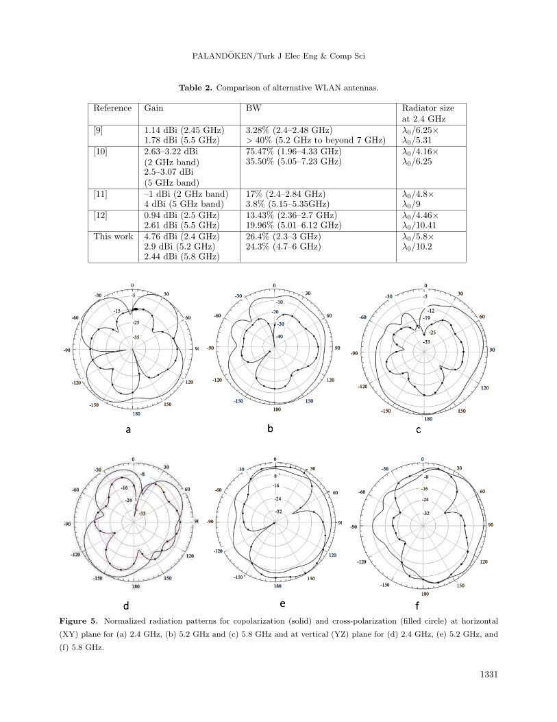
The normalized radiation patterns of the dual broadband WLAN antenna at three frequencies on the
horizontal (XY) and vertical (YZ) planes for co- and cross-polarizations are shown in Figure 5. The antenna
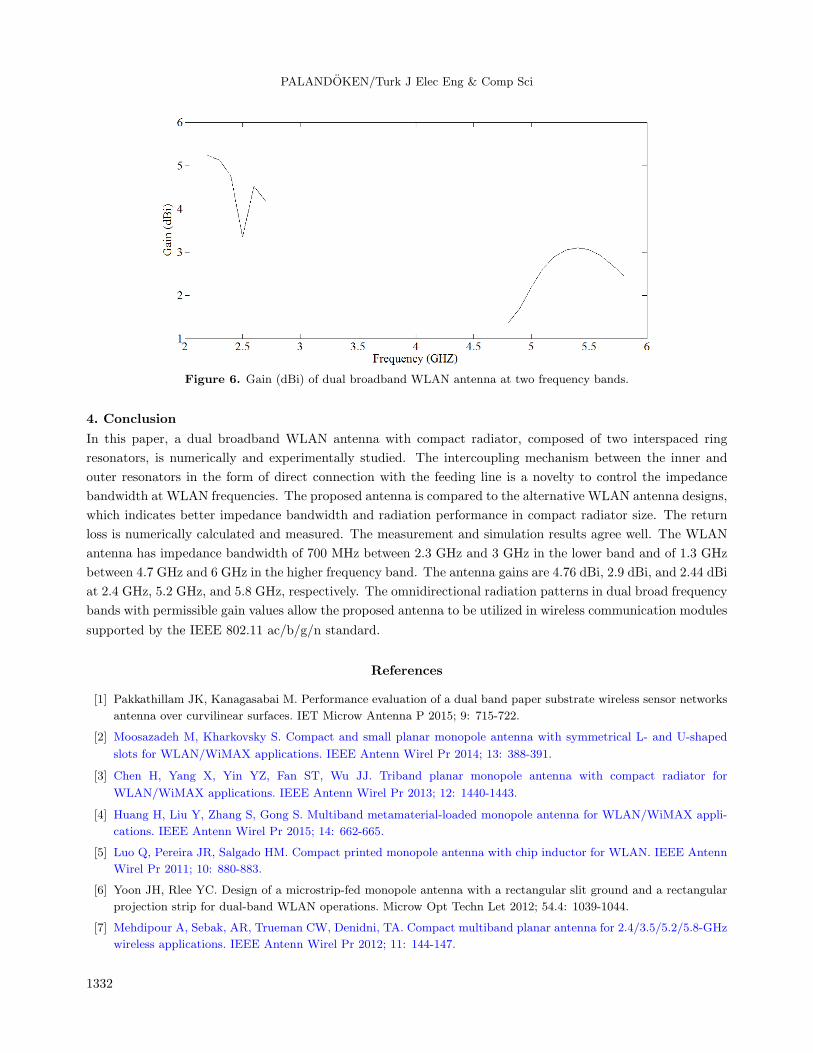
gain values for both frequency bands are also plotted in Figure 6. As shown in Figure 6, the gain is larger than
3.3 dBi in the lower frequency band with a maximum gain of 5.24 dBi at 2.2 GHz. The gain at the lower WLAN
frequency, 2.4 GHz, is 4.76 dBi. The gain in the higher frequency band is lower than that in the lower frequency
band. The reason for this is the oppositely directed magnetic dipoles in the inner and outer resonators, which
reduces the radiation efficiency and gain. However, the gain values are at an acceptable level with 2.9 dBi and
1329

PALANDOKEN/Turk J Elec Eng & Comp Sci
2.44 dBi at 5.2 GHZ and 5.8 GHz WLAN frequencies in the higher frequency band, respectively. The antenna
has almost omnidirectional radiation patterns for both polarizations, which makes the antenna positioning more
flexible due to a permissible signal receiving level at both polarizations.
Figure 3. Surface current distributions of WLAN antenna at (a) 2.45 GHz and (b) 5.5 GHz.
Figure 4. The effect of ground plane size on S11 for L15 = 12 mm (red), 22 mm (brown), and 32 mm (blue).
1330
PALANDOKEN/Turk J Elec Eng & Comp Sci
Table 2. Comparison of alternative WLAN antennas.
Reference Gain BW Radiator sizeat 2.4 GHz
[9] 1.14 dBi (2.45 GHz)1.78 dBi (5.5 GHz)
3.28% (2.4–2.48 GHz)> 40% (5.2 GHz to beyond 7 GHz)
λ0/6.25×λ0/5.31
[10] 2.63–3.22 dBi(2 GHz band)2.5–3.07 dBi(5 GHz band)
75.47% (1.96–4.33 GHz)35.50% (5.05–7.23 GHz)
λ0/4.16×λ0/6.25
[11] –1 dBi (2 GHz band)4 dBi (5 GHz band)
17% (2.4–2.84 GHz)3.8% (5.15–5.35GHz)
λ0/4.8×λ0/9
[12] 0.94 dBi (2.5 GHz)2.61 dBi (5.5 GHz)
13.43% (2.36–2.7 GHz)19.96% (5.01–6.12 GHz)
λ0/4.46×λ0/10.41
This work 4.76 dBi (2.4 GHz)2.9 dBi (5.2 GHz)2.44 dBi (5.8 GHz)
26.4% (2.3–3 GHz)24.3% (4.7–6 GHz)
λ0/5.8×λ0/10.2
Figure 5. Normalized radiation patterns for copolarization (solid) and cross-polarization (filled circle) at horizontal
(XY) plane for (a) 2.4 GHz, (b) 5.2 GHz and (c) 5.8 GHz and at vertical (YZ) plane for (d) 2.4 GHz, (e) 5.2 GHz, and
(f) 5.8 GHz.
1331
PALANDOKEN/Turk J Elec Eng & Comp Sci
Figure 6. Gain (dBi) of dual broadband WLAN antenna at two frequency bands.
4. Conclusion
In this paper, a dual broadband WLAN antenna with compact radiator, composed of two interspaced ring
resonators, is numerically and experimentally studied. The intercoupling mechanism between the inner and
outer resonators in the form of direct connection with the feeding line is a novelty to control the impedance
bandwidth at WLAN frequencies. The proposed antenna is compared to the alternative WLAN antenna designs,
which indicates better impedance bandwidth and radiation performance in compact radiator size. The return
loss is numerically calculated and measured. The measurement and simulation results agree well. The WLAN
antenna has impedance bandwidth of 700 MHz between 2.3 GHz and 3 GHz in the lower band and of 1.3 GHz
between 4.7 GHz and 6 GHz in the higher frequency band. The antenna gains are 4.76 dBi, 2.9 dBi, and 2.44 dBi
at 2.4 GHz, 5.2 GHz, and 5.8 GHz, respectively. The omnidirectional radiation patterns in dual broad frequency
bands with permissible gain values allow the proposed antenna to be utilized in wireless communication modules
supported by the IEEE 802.11 ac/b/g/n standard.
References
[1] Pakkathillam JK, Kanagasabai M. Performance evaluation of a dual band paper substrate wireless sensor networks
antenna over curvilinear surfaces. IET Microw Antenna P 2015; 9: 715-722.
[2] Moosazadeh M, Kharkovsky S. Compact and small planar monopole antenna with symmetrical L- and U-shaped
slots for WLAN/WiMAX applications. IEEE Antenn Wirel Pr 2014; 13: 388-391.
[3] Chen H, Yang X, Yin YZ, Fan ST, Wu JJ. Triband planar monopole antenna with compact radiator for
WLAN/WiMAX applications. IEEE Antenn Wirel Pr 2013; 12: 1440-1443.
[4] Huang H, Liu Y, Zhang S, Gong S. Multiband metamaterial-loaded monopole antenna for WLAN/WiMAX appli-
cations. IEEE Antenn Wirel Pr 2015; 14: 662-665.
[5] Luo Q, Pereira JR, Salgado HM. Compact printed monopole antenna with chip inductor for WLAN. IEEE Antenn
Wirel Pr 2011; 10: 880-883.
[6] Yoon JH, Rlee YC. Design of a microstrip-fed monopole antenna with a rectangular slit ground and a rectangular
projection strip for dual-band WLAN operations. Microw Opt Techn Let 2012; 54.4: 1039-1044.
[7] Mehdipour A, Sebak, AR, Trueman CW, Denidni, TA. Compact multiband planar antenna for 2.4/3.5/5.2/5.8-GHz
wireless applications. IEEE Antenn Wirel Pr 2012; 11: 144-147.
1332

PALANDOKEN/Turk J Elec Eng & Comp Sci
[8] Pei J, Wang AG, Gao S, Leng W. Miniaturized triple-band antenna with a defected ground plane for
WLAN/WiMAX applications. IEEE Antenn Wirel Pr 2011; 10: 298-301.
[9] Zhu J, Antoniades MA, Eleftheriades GV. A compact tri-band monopole antenna with single-cell metamaterial
loading. IEEE T Antenn Propag 2010; 58: 1031-1038.
[10] Yang K, Wang H, Lei Z, Xie Y, Lai H. CPW-fed slot antenna with triangular SRR terminated feedline for
WLAN/WiMAX applications. Electron Lett 2011; 47: 685-686.
[11] Basaran SC, Olgun U, Sertel K. Multiband monopole antenna with complementary split-ring resonators for WLAN
and WiMAX applications. Electron Lett 2013; 49: 636-638.
[12] Kang L, Wang H, Wang XH, Shi X. Compact ACS-fed monopole antenna with rectangular SRRs for tri-band
operation. Electron Lett 2014; 50: 1112-1114.
[13] Kim WS, Choi S, Jeong GT. A low-profile WLAN antenna with inductor and tuning stub for broadband impedance
matching. International Journal of Antennas and Propagation 2014; 2014: 452160.
[14] Zhou X, Quan XL, Li RL. A dual-broadband MIMO antenna system for GSM/UMTS/LTE and WLAN handsets.
IEEE Antenn Wirel Pr 2012; 11: 551-554.
[15] Liu P, Zou Y, Xie B, Liu X, Sun B. Compact CPW-fed tri-band printed antenna with meandering split-ring slot
for WLAN/WiMAX applications. IEEE Antenn Wirel Pr 2012; 11: 1242-1244.
[16] Palandoken M, Grede A, Henke H. Broadband microstrip antenna with left-handed metamaterials. IEEE T Antenn
Propag 2009; 57: 331-338.
[17] Palandoken M. Artificial materials based microstrip antenna design. In: Nasimuddin N, editor. Microstrip Antennas.
Rijeka, Croatia: InTech, 2011. pp. 43-68.
[18] Caloz C, Itoh T. Electromagnetic Metamaterials: Transmission Line Theory and Microwave Applications. 1st ed.
Hoboken, NJ, USA: Wiley, 2005.
1333