Embed Size (px)
Citation preview
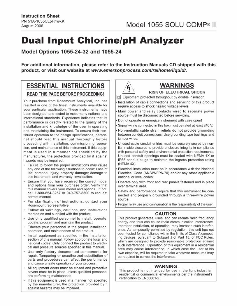
Dual Input Chlorine/pH AnalyzerModel Options 1055-24-32 and 1055-24
Instruction SheetPN 51A-1055CLpH/rev.K
August 2006
ESSENTIAL INSTRUCTIONSREAD THIS PAGE BEFORE PROCEEDING!
Your purchase from Rosemount Analytical, Inc. has
resulted in one of the finest instruments available for
your particular application. These instruments have
been designed, and tested to meet many national and
international standards. Experience indicates that its
performance is directly related to the quality of the
installation and knowledge of the user in operating
and maintaining the instrument. To ensure their con-
tinued operation to the design specifications, person-
nel should read this manual thoroughly before
proceeding with installation, commissioning, opera-
tion, and maintenance of this instrument. If this equip-
ment is used in a manner not specif ied by the
manufacturer, the protection provided by it against
hazards may be impaired.
• Failure to follow the proper instructions may causeany one of the following situations to occur: Loss oflife; personal injury; property damage; damage tothis instrument; and warranty invalidation.
• Ensure that you have received the correct modeland options from your purchase order. Verify thatthis manual covers your model and options. If not,call 1-800-854-8257 or 949-757-8500 to request correct manual.
• For clarification of instructions, contact yourRosemount representative.
• Follow all warnings, cautions, and instructionsmarked on and supplied with the product.
• Use only qualified personnel to install, operate,update, program and maintain the product.
• Educate your personnel in the proper installation,operation, and maintenance of the product.
• Install equipment as specified in the Installation section of this manual. Follow appropriate local andnational codes. Only connect the product to electri-cal and pressure sources specified in this manual.
• Use only factory documented components forrepair. Tampering or unauthorized substitution ofparts and procedures can affect the performanceand cause unsafe operation of your process.
• All equipment doors must be closed and protectivecovers must be in place unless qualified personnelare performing maintenance.
• If this equipment is used in a manner not specifiedby the manufacturer, the protection provided by itagainst hazards may be impaired.
WARNINGSRISK OF ELECTRICAL SHOCK
Equipment protected throughout by double insulation.
• Installation of cable connections and servicing of this productrequire access to shock hazard voltage levels.
• Main power and relay contacts wired to separate powersource must be disconnected before servicing.
• Do not operate or energize instrument with case open!
• Signal wiring connected in this box must be rated at least 240 V.
• Non-metallic cable strain reliefs do not provide groundingbetween conduit connections! Use grounding type bushings andjumper wires.
• Unused cable conduit entries must be securely sealed by non-flammable closures to provide enclosure integrity in compliancewith personal safety and environmental protection requirements.Unused conduit openings must be sealed with NEMA 4X orIP65 conduit plugs to maintain the ingress protection rating(NEMA 4X).
• Electrical installation must be in accordance with the NationalElectrical Code (ANSI/NFPA-70) and/or any other applicablenational or local codes.
• Operate only with front and rear panels fastened and in placeover terminal area.
• Safety and performance require that this instrument be con-nected and properly grounded through a three-wire powersource.
• Proper relay use and configuration is the responsibility of the user.
CAUTIONThis product generates, uses, and can radiate radio frequencyenergy and thus can cause radio communication interference.Improper installation, or operation, may increase such interfer-ence. As temporarily permitted by regulation, this unit has notbeen tested for compliance within the limits of Class A comput-ing devices, pursuant to Subpart J of Part 15, of FCC Rules,which are designed to provide reasonable protection againstsuch interference. Operation of this equipment in a residentialarea may cause interference, in which case the user at hisown expense, will be required to take whatever measures maybe required to correct the interference.
WARNINGThis product is not intended for use in the light industrial,residential or commercial environments per the instrument’scertification to EN50081-2.
Model 1055 SOLU COMP® II
For additional information, please refer to the Instruction Manuals CD shipped with this
product, or visit our website at www.emersonprocess.com/raihome/liquid/.
2
MODEL SOLU COMP II SPECIFICATIONS
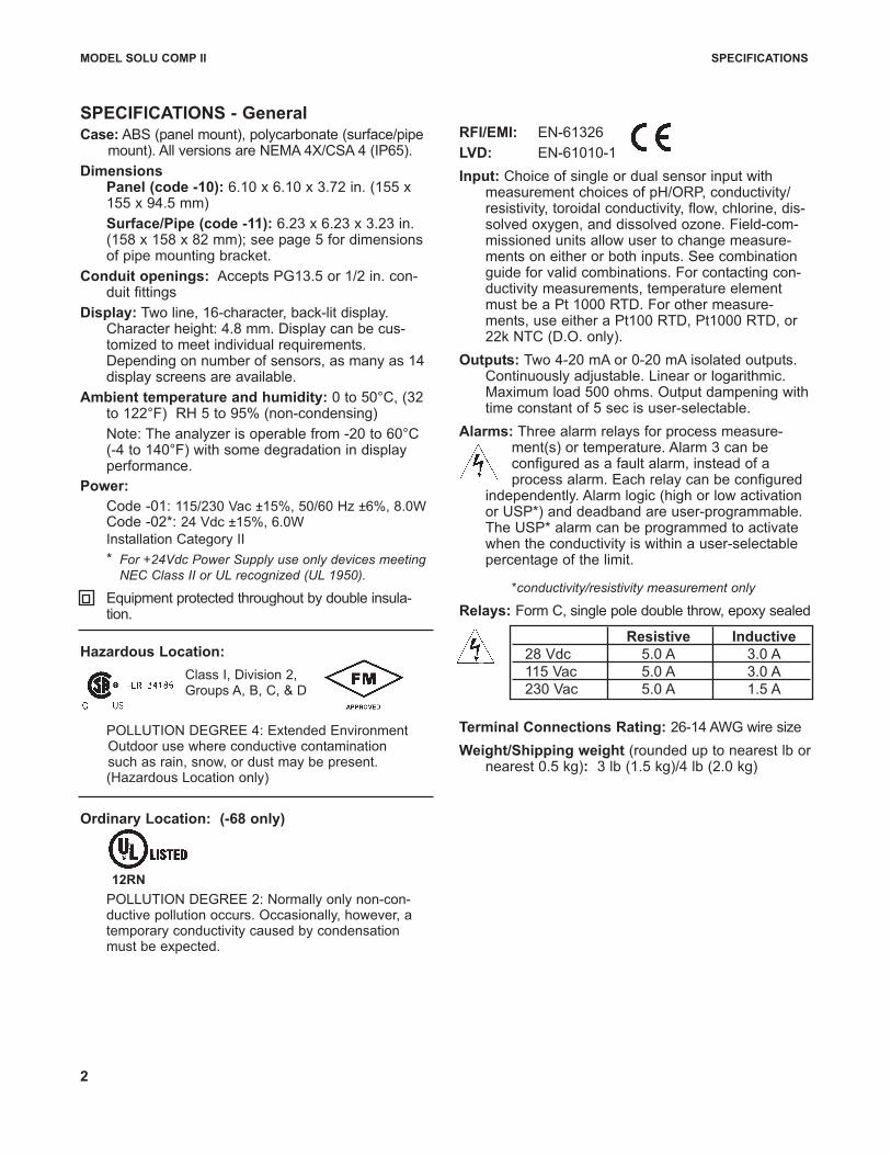
SPECIFICATIONS - GeneralCase: ABS (panel mount), polycarbonate (surface/pipe
mount). All versions are NEMA 4X/CSA 4 (IP65).
Dimensions Panel (code -10): 6.10 x 6.10 x 3.72 in. (155 x155 x 94.5 mm)
Surface/Pipe (code -11): 6.23 x 6.23 x 3.23 in.(158 x 158 x 82 mm); see page 5 for dimensionsof pipe mounting bracket.
Conduit openings: Accepts PG13.5 or 1/2 in. con-duit fittings
Display: Two line, 16-character, back-lit display.Character height: 4.8 mm. Display can be cus-tomized to meet individual requirements.Depending on number of sensors, as many as 14display screens are available.
Ambient temperature and humidity: 0 to 50°C, (32to 122°F) RH 5 to 95% (non-condensing)
Note: The analyzer is operable from -20 to 60°C(-4 to 140°F) with some degradation in displayperformance.
Power:
Code -01: 115/230 Vac ±15%, 50/60 Hz ±6%, 8.0WCode -02*: 24 Vdc ±15%, 6.0W
Installation Category II
* For +24Vdc Power Supply use only devices meeting NEC Class II or UL recognized (UL 1950).
Equipment protected throughout by double insula-tion.
Hazardous Location:
Class I, Division 2, Groups A, B, C, & D
POLLUTION DEGREE 4: Extended EnvironmentOutdoor use where conductive contamination such as rain, snow, or dust may be present.(Hazardous Location only)
RFI/EMI: EN-61326
LVD: EN-61010-1
Input: Choice of single or dual sensor input withmeasurement choices of pH/ORP, conductivity/resistivity, toroidal conductivity, flow, chlorine, dis-solved oxygen, and dissolved ozone. Field-com-missioned units allow user to change measure-ments on either or both inputs. See combinationguide for valid combinations. For contacting con-ductivity measurements, temperature elementmust be a Pt 1000 RTD. For other measure-ments, use either a Pt100 RTD, Pt1000 RTD, or22k NTC (D.O. only).
Outputs: Two 4-20 mA or 0-20 mA isolated outputs.Continuously adjustable. Linear or logarithmic.Maximum load 500 ohms. Output dampening withtime constant of 5 sec is user-selectable.
Alarms: Three alarm relays for process measure-ment(s) or temperature. Alarm 3 can be configured as a fault alarm, instead of a process alarm. Each relay can be configured
independently. Alarm logic (high or low activationor USP*) and deadband are user-programmable.The USP* alarm can be programmed to activatewhen the conductivity is within a user-selectablepercentage of the limit.
*conductivity/resistivity measurement only
Relays: Form C, single pole double throw, epoxy sealed
Terminal Connections Rating: 26-14 AWG wire size
Weight/Shipping weight (rounded up to nearest lb ornearest 0.5 kg): 3 lb (1.5 kg)/4 lb (2.0 kg)
Resistive Inductive
28 Vdc 5.0 A 3.0 A
115 Vac 5.0 A 3.0 A
230 Vac 5.0 A 1.5 A
Ordinary Location: (-68 only)
POLLUTION DEGREE 2: Normally only non-con-ductive pollution occurs. Occasionally, however, atemporary conductivity caused by condensationmust be expected.
12RN
3
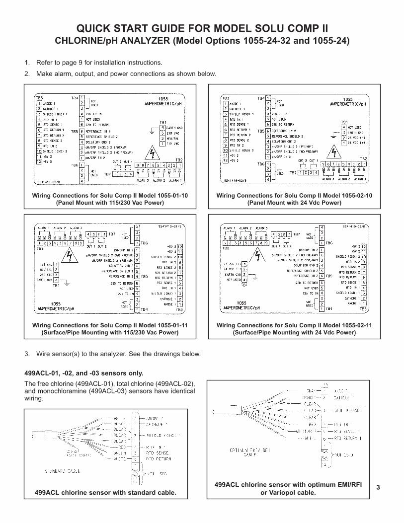
QUICK START GUIDE FOR MODEL SOLU COMP II CHLORINE/pH ANALYZER (Model Options 1055-24-32 and 1055-24)
1. Refer to page 9 for installation instructions.
2. Make alarm, output, and power connections as shown below.
3. Wire sensor(s) to the analyzer. See the drawings below.
Wiring Connections for Solu Comp II Model 1055-01-10
(Panel Mount with 115/230 Vac Power)
Wiring Connections for Solu Comp II Model 1055-02-10
(Panel Mount with 24 Vdc Power)
Wiring Connections for Solu Comp II Model 1055-01-11
(Surface/Pipe Mounting with 115/230 Vac Power)
Wiring Connections for Solu Comp II Model 1055-02-11
(Surface/Pipe Mounting with 24 Vdc Power)
499ACL-01, -02, and -03 sensors only.
The free chlorine (499ACL-01), total chlorine (499ACL-02),and monochloramine (499ACL-03) sensors have identicalwiring.
499ACL chlorine sensor with standard cable.
499ACL chlorine sensor with optimum EMI/RFI
or Variopol cable.
MODEL SOLU COMP II QUICK-START — WIRING
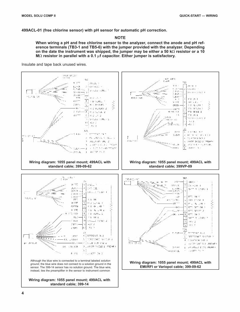
499ACL-01 (free chlorine sensor) with pH sensor for automatic pH correction.
NOTE
When wiring a pH and free chlorine sensor to the analyzer, connect the anode and pH ref-erence terminals (TB3-1 and TB5-6) with the jumper provided with the analyzer. Dependingon the date the instrument was shipped, the jumper may be either a 50 kΩ resistor or a 10MΩ resistor in parallel with a 0.1 μf capacitor. Either jumper is satisfactory.
Insulate and tape back unused wires.
Wiring diagram: 1055 panel mount; 499ACL with
standard cable; 399-09-62
Wiring diagram: 1055 panel mount; 499ACL with
standard cable; 399VP-09
Wiring diagram: 1055 panel mount; 499ACL with
standard cable; 399-14
Wiring diagram: 1055 panel mount; 499ACL with
EMI/RFI or Variopol cable; 399-09-62
Although the blue wire is connected to a terminal labeled solutionground, the blue wire does not connect to a solution ground in the
sensor. The 399-14 sensor has no solution ground. The blue wire,
instead, ties the preamplifier in the sensor to instrument common
4
MODEL SOLU COMP II QUICK-START — WIRING
5
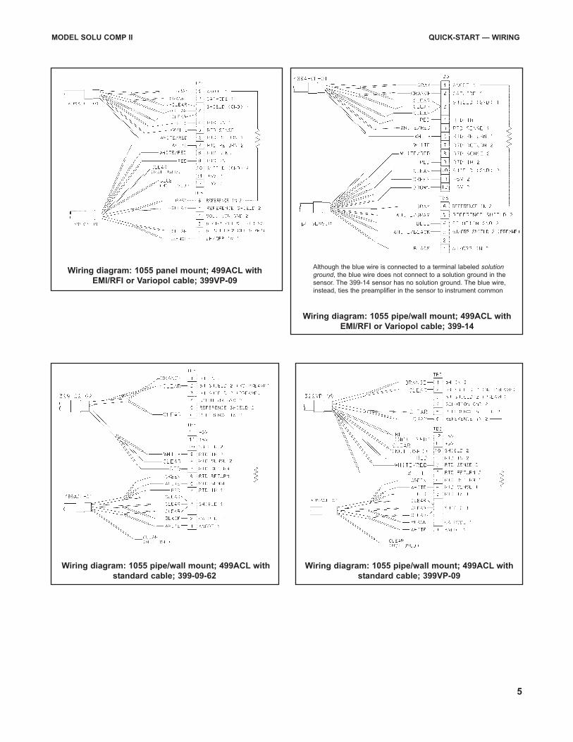
Wiring diagram: 1055 panel mount; 499ACL with
EMI/RFI or Variopol cable; 399VP-09
Wiring diagram: 1055 pipe/wall mount; 499ACL with
EMI/RFI or Variopol cable; 399-14
Wiring diagram: 1055 pipe/wall mount; 499ACL with
standard cable; 399-09-62
Wiring diagram: 1055 pipe/wall mount; 499ACL with
standard cable; 399VP-09
Although the blue wire is connected to a terminal labeled solutionground, the blue wire does not connect to a solution ground in the
sensor. The 399-14 sensor has no solution ground. The blue wire,
instead, ties the preamplifier in the sensor to instrument common
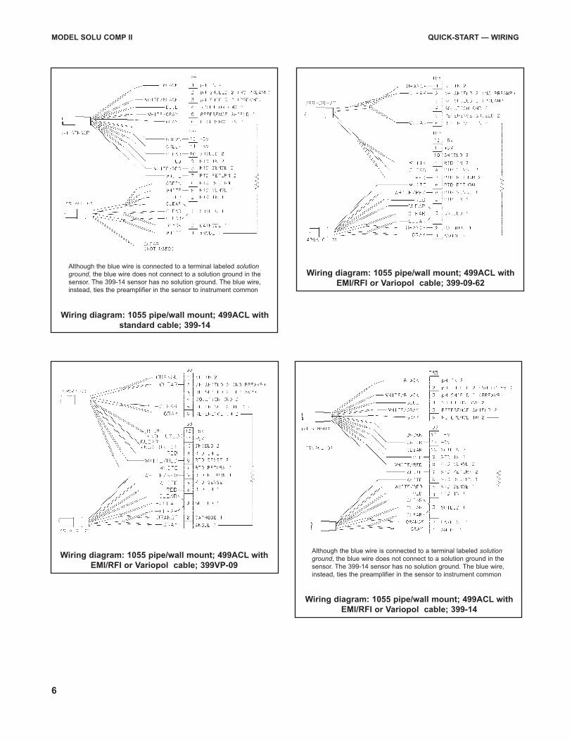
MODEL SOLU COMP II QUICK-START — WIRING
6
Wiring diagram: 1055 pipe/wall mount; 499ACL with
standard cable; 399-14
Wiring diagram: 1055 pipe/wall mount; 499ACL with
EMI/RFI or Variopol cable; 399-09-62
Wiring diagram: 1055 pipe/wall mount; 499ACL with
EMI/RFI or Variopol cable; 399VP-09
Wiring diagram: 1055 pipe/wall mount; 499ACL with
EMI/RFI or Variopol cable; 399-14
Although the blue wire is connected to a terminal labeled solutionground, the blue wire does not connect to a solution ground in the
sensor. The 399-14 sensor has no solution ground. The blue wire,
instead, ties the preamplifier in the sensor to instrument common
Although the blue wire is connected to a terminal labeled solutionground, the blue wire does not connect to a solution ground in the
sensor. The 399-14 sensor has no solution ground. The blue wire,
instead, ties the preamplifier in the sensor to instrument common
7
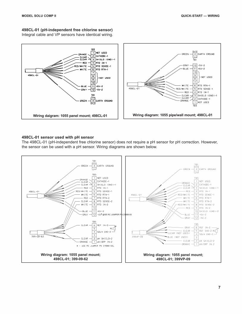
498CL-01 (pH-independent free chlorine sensor)
Integral cable and VP sensors have identical wiring.
MODEL SOLU COMP II QUICK-START — WIRING
Wiring diagram: 1055 pipe/wall mount; 498CL-01Wiring daigram: 1055 panel mount; 498CL-01
Wiring diagram: 1055 panel mount;
498CL-01; 399-09-62Wiring diagram: 1055 panel mount;
498CL-01; 399VP-09
498CL-01 sensor used with pH sensor
The 498CL-01 (pH-independent free chlorine sensor) does not require a pH sensor for pH correction. However,
the sensor can be used with a pH sensor. Wiring diagrams are shown below.
* USE RC JUMPER PN 23988-00
8
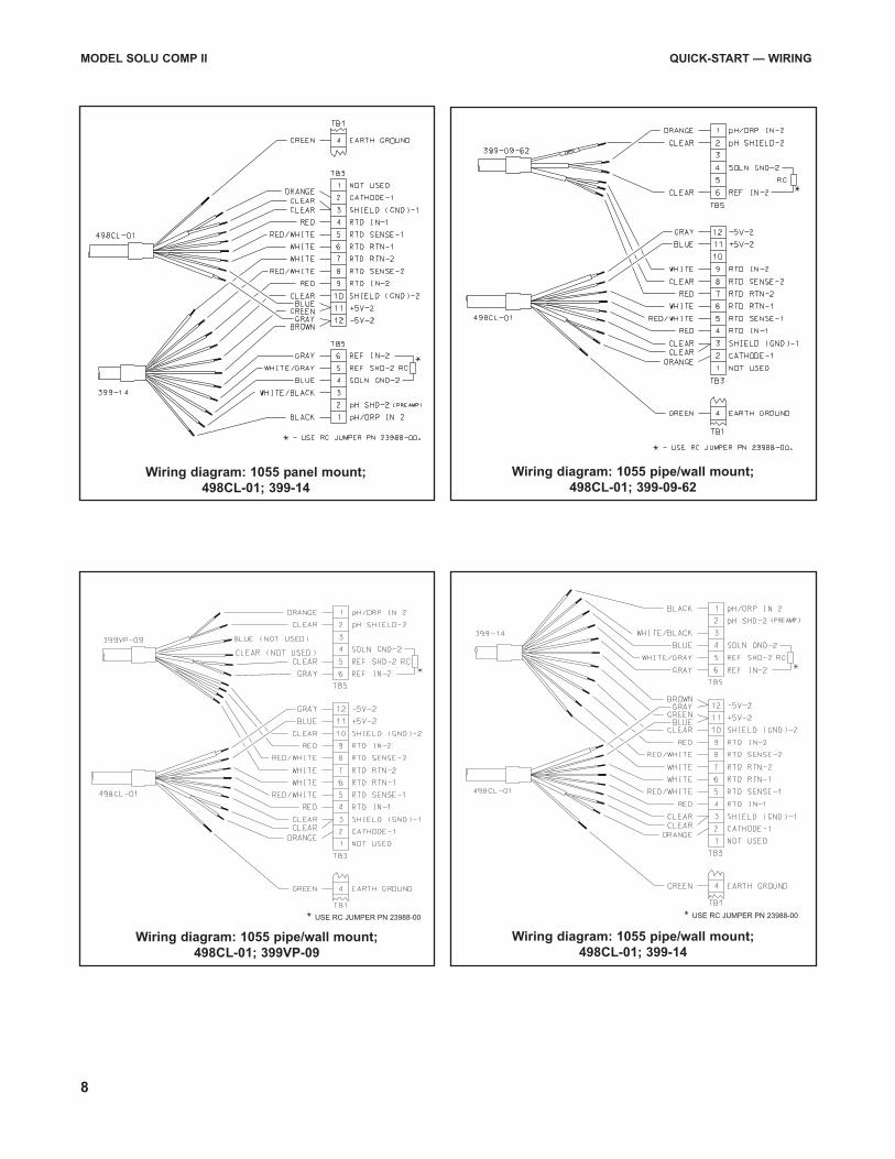
Wiring diagram: 1055 pipe/wall mount;
498CL-01; 399VP-09
Wiring diagram: 1055 pipe/wall mount;
498CL-01; 399-14
MODEL SOLU COMP II QUICK-START — WIRING
Wiring diagram: 1055 panel mount;
498CL-01; 399-14
Wiring diagram: 1055 pipe/wall mount;
498CL-01; 399-09-62
* USE RC JUMPER PN 23988-00* USE RC JUMPER PN 23988-00
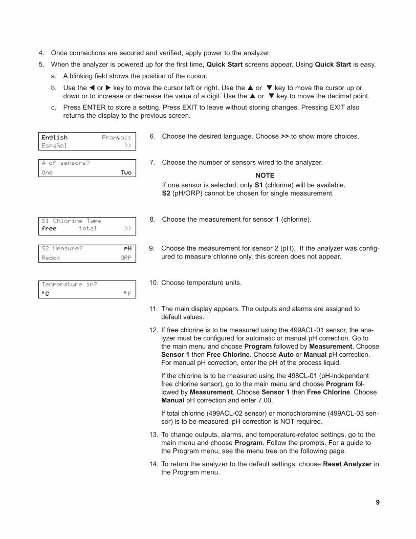
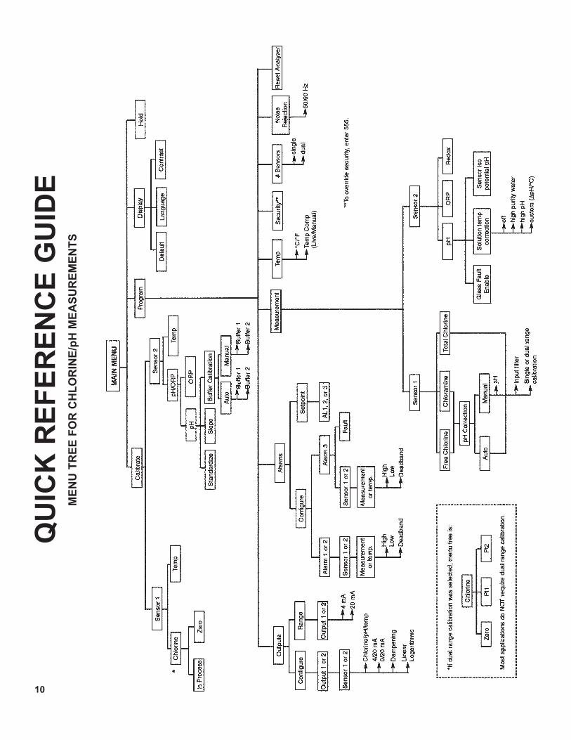
9. Choose the measurement for sensor 2 (pH). If the analyzer was config-
ured to measure chlorine only, this screen does not appear.
10. Choose temperature units.
11. The main display appears. The outputs and alarms are assigned to
default values.
12. If free chlorine is to be measured using the 499ACL-01 sensor, the ana-
lyzer must be configured for automatic or manual pH correction. Go to
the main menu and choose Program followed by Measurement. Choose
Sensor 1 then Free Chlorine. Choose Auto or Manual pH correction.
For manual pH correction, enter the pH of the process liquid.
If the chlorine is to be measured using the 498CL-01 (pH-independent
free chlorine sensor), go to the main menu and choose Program fol-
lowed by Measurement. Choose Sensor 1 then Free Chlorine. Choose
Manual pH correction and enter 7.00.
If total chlorine (499ACL-02 sensor) or monochloramine (499ACL-03 sen-
sor) is to be measured, pH correction is NOT required.
13. To change outputs, alarms, and temperature-related settings, go to the
main menu and choose Program. Follow the prompts. For a guide to
the Program menu, see the menu tree on the following page.
14. To return the analyzer to the default settings, choose Reset Analyzer in
the Program menu.
Temperature in?
°C °F
S2 Measure? pH
Redox ORP
4. Once connections are secured and verified, apply power to the analyzer.
5. When the analyzer is powered up for the first time, Quick Start screens appear. Using Quick Start is easy.
a. A blinking field shows the position of the cursor.
b. Use the � or � key to move the cursor left or right. Use the � or � key to move the cursor up or
down or to increase or decrease the value of a digit. Use the � or � key to move the decimal point.
c. Press ENTER to store a setting. Press EXIT to leave without storing changes. Pressing EXIT also
returns the display to the previous screen.
9
6. Choose the desired language. Choose >> to show more choices.
7. Choose the number of sensors wired to the analyzer.
NOTE
If one sensor is selected, only S1 (chlorine) will be available.
S2 (pH/ORP) cannot be chosen for single measurement.
8. Choose the measurement for sensor 1 (chlorine).
# of sensors?
One Two
S1 Chlorine Type
free total >>
English Fran�ais
Espa�ol >>
QU
ICK
RE
FE
RE
NC
E G
UID
EM
EN
U T
RE
E F
OR
CH
LO
RIN
E/p
H M
EA
SU
RE
ME
NT
S
10
11
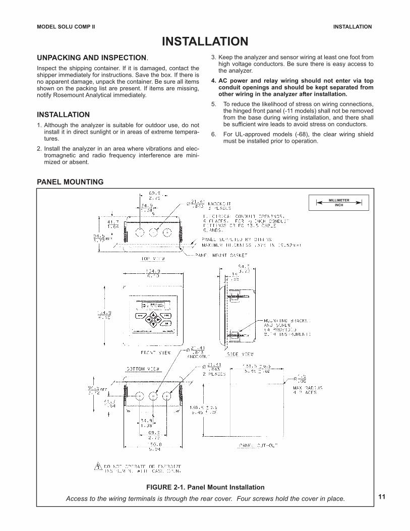
FIGURE 2-1. Panel Mount Installation
Access to the wiring terminals is through the rear cover. Four screws hold the cover in place.
MILLIMETER
INCH
INSTALLATION
UNPACKING AND INSPECTION.
Inspect the shipping container. If it is damaged, contact theshipper immediately for instructions. Save the box. If there isno apparent damage, unpack the container. Be sure all itemsshown on the packing list are present. If items are missing,notify Rosemount Analytical immediately.
INSTALLATION
1. Although the analyzer is suitable for outdoor use, do notinstall it in direct sunlight or in areas of extreme tempera-tures.
2. Install the analyzer in an area where vibrations and elec-tromagnetic and radio frequency interference are mini-mized or absent.
3. Keep the analyzer and sensor wiring at least one foot fromhigh voltage conductors. Be sure there is easy access tothe analyzer.
4. AC power and relay wiring should not enter via topconduit openings and should be kept separated fromother wiring in the analyzer after installation.
5. To reduce the likelihood of stress on wiring connections,the hinged front panel (-11 models) shall not be removedfrom the base during wiring installation, and there shallbe sufficient wire leads to avoid stress on conductors.
6. For UL-approved models (-68), the clear wiring shieldmust be installed prior to operation.
MODEL SOLU COMP II INSTALLATION
PANEL MOUNTING
MODEL SOLU COMP II INSTALLATION
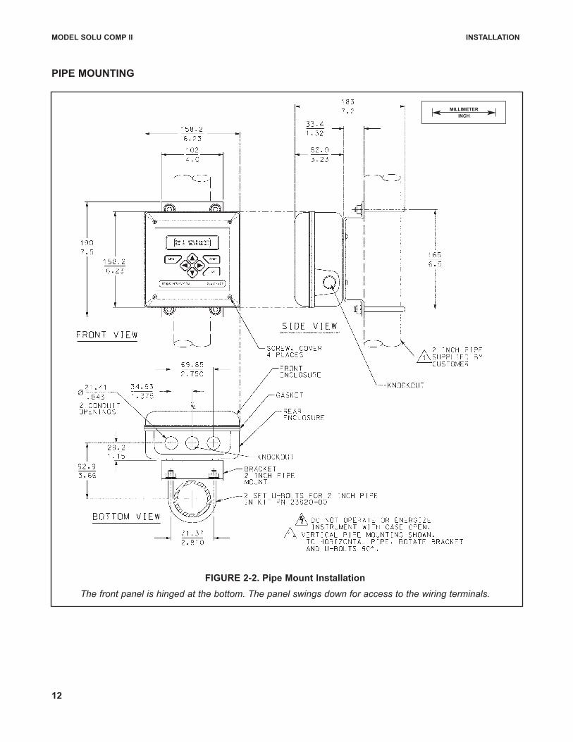
FIGURE 2-2. Pipe Mount Installation
The front panel is hinged at the bottom. The panel swings down for access to the wiring terminals.
PIPE MOUNTING
MILLIMETER
INCH
12
MODEL SOLU COMP II INSTALLATION
13
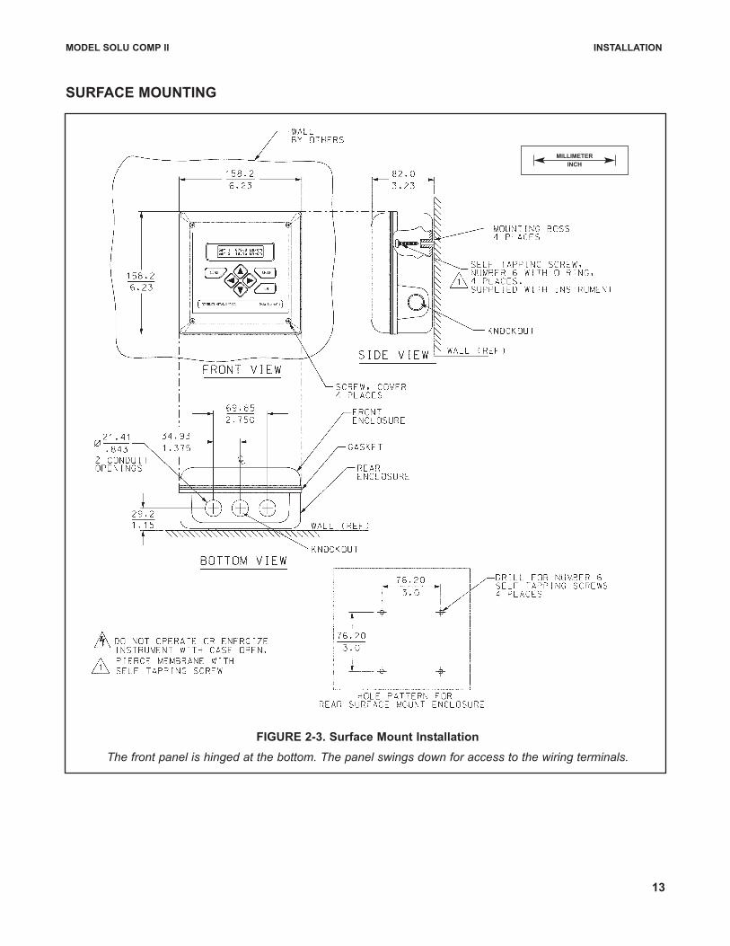
FIGURE 2-3. Surface Mount Installation
The front panel is hinged at the bottom. The panel swings down for access to the wiring terminals.
SURFACE MOUNTING
MILLIMETER
INCH

14
NOTES:
15
CALIBRATION
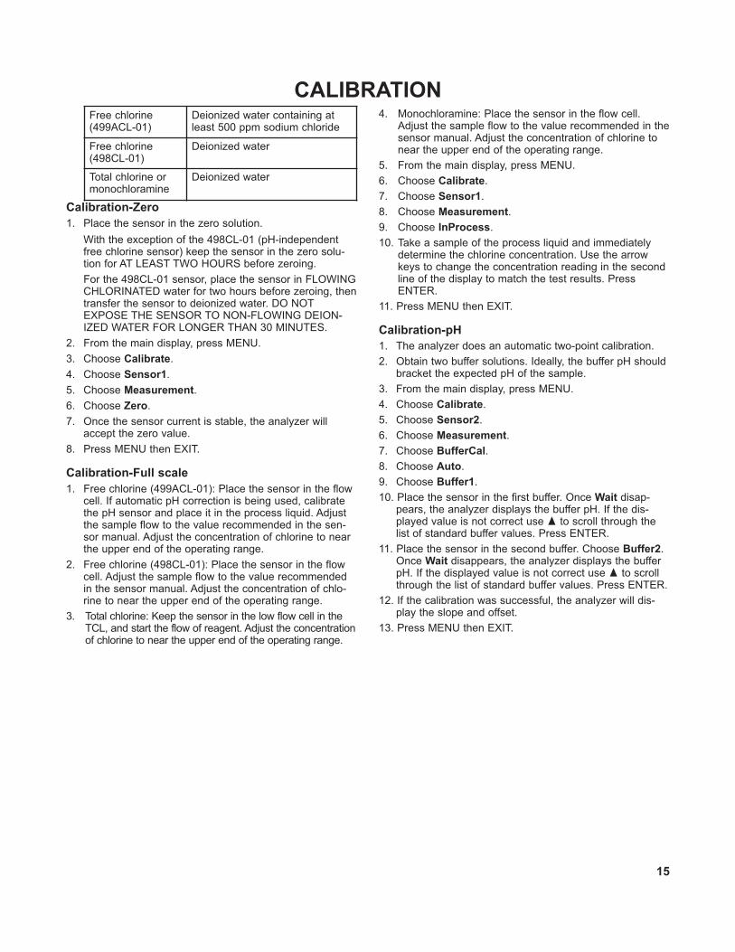
Calibration-Zero
1. Place the sensor in the zero solution.
With the exception of the 498CL-01 (pH-independentfree chlorine sensor) keep the sensor in the zero solu-tion for AT LEAST TWO HOURS before zeroing.
For the 498CL-01 sensor, place the sensor in FLOWINGCHLORINATED water for two hours before zeroing, thentransfer the sensor to deionized water. DO NOTEXPOSE THE SENSOR TO NON-FLOWING DEION-IZED WATER FOR LONGER THAN 30 MINUTES.
2. From the main display, press MENU.
3. Choose Calibrate.
4. Choose Sensor1.
5. Choose Measurement.
6. Choose Zero.
7. Once the sensor current is stable, the analyzer willaccept the zero value.
8. Press MENU then EXIT.
Calibration-Full scale
1. Free chlorine (499ACL-01): Place the sensor in the flowcell. If automatic pH correction is being used, calibratethe pH sensor and place it in the process liquid. Adjustthe sample flow to the value recommended in the sen-sor manual. Adjust the concentration of chlorine to nearthe upper end of the operating range.
2. Free chlorine (498CL-01): Place the sensor in the flowcell. Adjust the sample flow to the value recommendedin the sensor manual. Adjust the concentration of chlo-rine to near the upper end of the operating range.
3. Total chlorine: Keep the sensor in the low flow cell in theTCL, and start the flow of reagent. Adjust the concentrationof chlorine to near the upper end of the operating range.
4. Monochloramine: Place the sensor in the flow cell.Adjust the sample flow to the value recommended in thesensor manual. Adjust the concentration of chlorine tonear the upper end of the operating range.
5. From the main display, press MENU.
6. Choose Calibrate.
7. Choose Sensor1.
8. Choose Measurement.
9. Choose InProcess.
10. Take a sample of the process liquid and immediatelydetermine the chlorine concentration. Use the arrowkeys to change the concentration reading in the secondline of the display to match the test results. PressENTER.
11. Press MENU then EXIT.
Calibration-pH
1. The analyzer does an automatic two-point calibration.
2. Obtain two buffer solutions. Ideally, the buffer pH shouldbracket the expected pH of the sample.
3. From the main display, press MENU.
4. Choose Calibrate.
5. Choose Sensor2.
6. Choose Measurement.
7. Choose BufferCal.
8. Choose Auto.
9. Choose Buffer1.
10. Place the sensor in the first buffer. Once Wait disap-pears, the analyzer displays the buffer pH. If the dis-played value is not correct use � to scroll through thelist of standard buffer values. Press ENTER.
11. Place the sensor in the second buffer. Choose Buffer2.Once Wait disappears, the analyzer displays the bufferpH. If the displayed value is not correct use � to scrollthrough the list of standard buffer values. Press ENTER.
12. If the calibration was successful, the analyzer will dis-play the slope and offset.
13. Press MENU then EXIT.
Free chlorine(499ACL-01)
Deionized water containing atleast 500 ppm sodium chloride
Free chlorine(498CL-01)
Deionized water
Total chlorine or monochloramine
Deionized water
Credit Cards for U.S. Purchases Only.
The right people,the right answers,right now. ON-LINE ORDERING NOW AVAILABLE ON OUR WEB SITE
http://www.raihome.com
Specifications subject to change without notice.
Emerson Process Management
Liquid Division2400 Barranca Parkway
Irvine, CA 92606 USA
Tel: (949) 757-8500
Fax: (949) 474-7250
http://www.raihome.com
© Rosemount Analytical Inc. 2006