Embed Size (px)
Citation preview

Dual-modality endomicroscopy withco-registered fluorescence and phase contrastC. BA,* M. PALMIERE, J. RITT, AND J. MERTZBiomedical Engineering Department, Boston University, 44 Cummington Mall, Boston, MA 02215, USA*[email protected]
Abstract: We describe a dual-modality laser scanning endomicroscope that provides simulta-neous fluorescence contrast based on confocal laser endomicroscopy (CLE) and phase-gradientcontrast based on scanning oblique back-scattering microscopy (sOBM). The probe consistsof a 2.6mm-diameter micro-objective attached to a 30,000-core flexible fiber bundle. The dualcontrasts are inherently co-registered, providing complementary information on labeled and un-labeled sample structure. Proof of principle demonstrations are presented with ex-vivo mousecolon tissue.c⃝ 2016 Optical Society of AmericaOCIS codes: (170.2150) Endoscopic imaging; (180.5810) Scanning microscopy; (120.5050) Phase measurement;(170.1790) Confocal microscopy.
References and links1. T. J. Muldoon, M. C. Pierce, D. L. Nida, M. D. Williams, A. Gillenwater and R. Richards-Kortum, “Subcellular-
resolution molecular imaging within living tissue by fiber microendoscopy," Opt. Express 15, 16413–16423 (2007).2. M. C. Pierce, D. J. Javier and R. Richards-Kortum, “Optical contrast agents and imaging systems for detection and
diagnosis of cancer," Int. J. Cancer 123, 1979–1990 (2008).3. W. Zhong, J. P. Celli, I. Rizvi, Z. Mai, B. Q. Spring, S. H. Yun, and T. Hasan, “In vivo high-resolution fluorescence
microendoscopy for ovarian cancer detection and treatment monitoring," Br. J. Cancer 101, 2015–2022 (2009).4. A. F. Gmitro and D. Aziz, “Confocal microscopy through a fiber-optic imaging bundle," Opt. Lett. 18, 565–567
(1993).5. P. S. P. Thong, M. Olivo, K. W. Kho, W. Zheng, K. Mancer, M. Harris and K. C. Soo, “Laser confocal endomi-
croscopy as a novel technique for fluorescence diagnostic imaging of the oral cavity," J. Biomed. Opt. 12, 014007(2007).
6. M. A. A. Neil, R. Juskaitis and T. Wilson, “Method of obtaining optical sectioning by using structured light in aconventional microscope," Opt. Lett. 22, 1905–1907 (1997).
7. N. Bozinovic, C. Ventalon, T. Ford and J. Mertz, “Fluorescence endomicroscopy with structured illumination," Opt.Express 16, 8016–8025 (2008).
8. S. Santos, K. K. Chu, D. Lim, N. Bozinovic, T. N. Ford, C. Hourtoule, A. C. Bartoo, S. K. Singh and J. Mertz, “Op-tically sectioned fluorescence endomicroscopy with hybrid-illumination imaging through a flexible fiber bundle," J.Biomed. Opt. 14, 030502 (2009).
9. K. Murari, Y. Zhang, S. Li, Y. Chen, M. J. Li and X. Li, “Compensation-free, all-fiber-optic, two-photon endomi-croscopy at 1.55 µm," Opt. Lett. 36, 1299–1301 (2011).
10. D. M. Huland, C. M. Brown, S. S. Howard, D. G. Ouzounov, I. Pavlova, K. Wang, D. R. Rivera, W. W. Webb and C.Xu. “In vivo imaging of unstained tissues using long gradient index lens multiphoton endoscopic systems," Biomed.Opt. Express 3, 1077–1085 (2012).
11. G. Ducourthial, P. Leclerc, T. Mansuryan, M. Fabert, J. Brevier, R. Habert, F. Braud, R. Batrin, C. Vever-Bizet,G. Bourg-Heckly, L. Thiberville, A. Druilhe, A. Kudlinski and F. Louradour, “Development of a real-time flexiblemultiphoton microendoscope for label-free imaging in a live animal," Sci. Rep. 5, 18303 (2015).
12. B. Viellerobe, A. Osdoit, C. Cavé, F. Lacombe, S. Loiseau, and B. Abrat, “Mauna Kea technologies’ F400 proto-type: a new tool for in vivo microscopic imaging during endoscopy," in Biomedical Optics 2006, 60820C-60820C.International Society for Optics and Photonics, 2006.
13. P. L. Hsiung, J. Hardy, S. Friedland, R. Soetikno, C. B. Du, A. P. Wu, P. Sahbaie, J. M. Crawford, A. W. Lowe,C. H. Contag and T. D. Wang, “Detection of colonic dysplasia in vivo using a targeted heptapeptide and confocalmicroendoscopy," Nat. Med. 14, 454–458 (2008).
14. H. Li, Y. Li, L. Cui, B. Wang, W. Cui, M. Li and Y. Cheng, “Monitoring pancreatic carcinogenesis by the molecularimaging of cathepsin E in vivo using confocal laser endomicroscopy," PloS One 9, e106566 (2014).
15. K. C. Lee, S. Sharma, J. B. Tuttle and W. D. Steers, “Origin and characterization of retrograde labeled neuronssupplying the rat urethra using fiberoptic confocal fluorescent microscopy in vivo and immunohistochemistry," J.Urology 184, 1550–1554 (2010).
Vol. 7, No. 9 | 1 Sep 2016 | BIOMEDICAL OPTICS EXPRESS 3403
#267581 Journal © 2016
http://dx.doi.org/10.1364/BOE.7.003403 Received 7 Jun 2016; revised 8 Aug 2016; accepted 8 Aug 2016; published 10 Aug 2016

16. Q. T. Nguyen and R. Y. Tsien, “Fluorescence-guided surgery with live molecular navigation - a new cutting edge,"Nat. Rev. Cancer 13, 653–662 (2013).
17. W. A. Welge, a. T. DeMarco, J. M. Watson, P. S. Rice, J. K. Barton and M. A. Kupinski, “Diagnostic potentialof multimodal imaging of ovarian tissue using optical coherence tomography and second-harmonic generationmicroscopy," J. Med. Imaging 1, 025501 (2014).
18. C. Joo, K. H. Kim and J. F. de Boer, “Spectral-domain optical coherence phase and multiphoton microscopy," Opt.Lett. 32, 623–625 (2007).
19. C. Liang, M. Descour, K. B. Sung and R. Richards-Kortum, “Fiber confocal reflectance microscope (FCRM) forin-vivo imaging," Opt. Express 9, 821–830 (2001).
20. D. C. Adler, Y. Chen, R. Huber, J. Schmitt, J. Connolly and G. J. Fujimoto, “Three-dimensional endomicroscopyusing optical coherence tomography," Nat. Photon. 1, 709–716 (2007).
21. J. Xi, Y. Chen, Y. Zhang, K. Murari, M. J. Li and X. Li, “Integrated multimodal endomicroscopy platform forsimultaneous en face optical coherence and two-photon fluorescence imaging," Opt. Lett. 37, 362–364 (2012).
22. V. Tuchin, Tissue Optics: Light Scattering Methods and Instruments for Medical Diagnosis, Vol. 13, (Bellingham:SPIE press, 2007).
23. G. Nomarski, “Differential microinterferometer with polarized waves," J. Phys. Radium 16, 9S-11S (1955).24. F. Zernike, “Phase contrast, a new method for the microscopic observation of transparent objects," Physica 9, 686–
698 (1942).25. R. Yi, K. K. Chu and J. Mertz, “Graded-field microscopy with white light," Opt. Express 14, 5191–5200 (2006).26. S. B. Mehta and C. J. R. Sheppard, “Quantitative phase-gradient imaging at high resolution with asymmetric
illumination-based differential phase contrast," Opt. Lett. 34, 1924–1926 (2009).27. X. Ou, R. Horstmeyer, C. Yang and G. Zheng, “Quantitative phase imaging via Fourier ptychographic microscopy,"
Opt. Lett. 38, 4845–4848 (2013).28. A. B. Parthasarathy, K. K. Chu, T. N. Ford and J. Mertz, “Quantitative phase imaging using a partitioned detection
aperture," Opt. Lett. 37, 4062–4064 (2012).29. C. Mann, L. Yu, C. M. Lo and M. Kim, “High-resolution quantitative phase-contrast microscopy by digital holog-
raphy," Opt. Express 13, 8693–8698 (2005).30. C. G. Rylander, D. P. Davé, T. Akkin, T. E. Milner, K. R. Diller and A. J. Welch, “Quantitative phase-contrast
imaging of cells with phase-sensitive optical coherence microscopy," Opt. Lett. 29, 1509–1511 (2004).31. T. N. Ford and J. Mertz, “Video-rate imaging of microcirculation with single-exposure oblique back-illumination
microscopy," J. Biomed. Opt. 18, 066007 (2013).32. T. N. Ford, K. K. Chu and J. Mertz, “Phase-gradient microscopy in thick tissue with oblique back-illumination,"
Nat. Methods 9, 1195–1197 (2012).33. L. P. Hariri, A. R. Tumlinson, D. G. Besselsen, U. Utzinger, E. W. Gerner and J. K. Barton, “Endoscopic optical
coherence tomography and laserâARinduced fluorescence spectroscopy in a murine colon cancer model," LasersSurg Med 38, 305–313 (2006).
34. J. Mertz, A. Gasecka, A. Daradich, I. Davison, and D. Coté, “Phase-gradient contrast in thick tissue with a scanningmicroscope," Biomed. Opt. Express 5, 407–416 (2014).
35. D. K. Hamilton, and C. J. R. Sheppard, “Differential phase contrast in scanning optical microscopy," J. Microscopy133, 27–39 (1984).
36. Y. Kawata, R. Juskaitis, T. Tanaka, T. Wilson, and S. Kawata, “Differential phase-contrast microscope with a splitdetector for the readout system of a multilayered optical memory," Appl. Opt. 35, 2466–2470 (1996).
37. W. B. Amos, S. Reichelt, D. M. Cattermole and J. Laufer, “Re-evaluation of differential phase contrast (DPC) in ascanning laser microscope using a split detector as an alternative to differential interference contrast (DIC) optics,"J. Microsc. 210, 166–175 (2003).
38. T. Y. Chui, T. J. Gast and S. A. Burns, “Imaging of Vascular Wall Fine Structure in the Human Retina UsingAdaptive Optics Scanning Laser Ophthalmoscopy Vascular Wall Imaging Using AOSLO," Invest. Ophthalmol. Vis.Sci. 54, 7115–7124 (2013).
39. D. Scoles, Y. N. Sulai, C. S. Langlo, G. A. Fishman, C. A. Curcio, J. Carroll and A. Dubra, “In Vivo Imaging ofHuman Cone Photoreceptor Inner SegmentsIn Vivo Imaging of Photoreceptor Inner Segments," Invest. Ophthalmol.Vis. Sci. 55, 4244–4251 (2014).
40. D. Cunefare, R. F. Cooper, B. Higgins, D. F. Katz, A. Dubra, J. Carroll and S. Farsiu, “Automatic detection of conephotoreceptors in split detector adaptive optics scanning light ophthalmoscope images," Biomed. Opt. Express 7,2036–2050 (2012).
41. T. N. Ford, D. Lim and J. Mertz, “Fast optically sectioned fluorescence HiLo endomicroscopy," J. Biomed. Opt. 17,0211051 (2012).
1. IntroductionFluorescence endomicroscopy has garnered attention in recent years for its ability to providehistology-like high resolution images in situ and in real time. Standard non-scanning fluores-cence endomicroscopy [1] is already widely used in clinical applications, especially for can-
Vol. 7, No. 9 | 1 Sep 2016 | BIOMEDICAL OPTICS EXPRESS 3404

cer detection [2, 3]. Approaches that provide optical sectioning such as confocal laser endomi-croscopy (CLE) [4, 5], structured illumination [6–8] or two-photon excitation [9–11] have alsogained traction. For example, commercial implementations of CLE [12] have been adopted forapplications ranging from disease development to drug delivery to neuroscience [13–15]. Somelimitations of fluorescence imaging, however, are that it generally requires labeling with anexogenous contrast agent, few of which are approved for clinical applications [16]. Anotherlimitation is that fluorescence reveals only what is labeled. While such specificity provides dis-tinct advantages in many applications, it also presents disadvantages. Often, it is desirable toplace the fluorescence in the context of its unlabeled environment. For example, when imagingfluorescent cells in tissue, it is often desirable to complement this with information on the sur-rounding unlabeled extracellular matrix, collagen distributions, vascular morphology, etc., allof which can provide pathology signatures of their own [17]. In these cases, an endomicroscopeproviding simultaneous fluorescence and label-free structural imaging becomes attractive [18].We describe here such a device, which features the advantage that fluorescence and structuralimaging are derived from the same illumination source and are automatically co-registered.Two well-known label-free endomicroscopy techniques are fiber-optic-based confocal reflec-
tion microscopy (FCRM) [19] and optical coherence tomography (OCT) [20,21]. These producesignal derived from light backscattered directly from the focal plane. That is, they intrinsicallyreveal only sharply varying structure in the axial direction, such as layered structure of retinaor the surface of skin, and cannot reveal more slowly varying structure (i.e. structure contain-ing spatial frequencies too low to cause light to reverse its direction). Unfortunately, biologicaltissue is comprised mostly of such slowly varying structure since it is mostly forward scatte-ring [22]. In addition, FCRM and OCT both suffer from speckle noise, which can compromisethe information content of the acquired images.Another candidate for label-free structural imaging is phase-contrast imaging, which is
widely used in biomedical applications because it can provide images of unlabeled and almosttransparent samples. However, most phase-contrast techniques are based on trans-illuminationgeometries that can hardly be adopted for endomicroscopy, such as Normarski differential inter-ference contrast (DIC) [23], Zernike phase contrast [24], oblique illumination/detection [25–28]or holographic techniques [29], to name a few. One exception is phase-contrast OCT [30], whichoperates in an en-face geometry, but again is limited to imaging only sharply varying structures.To address the above limitations we introduced oblique back-illumination microscopy
(OBM), which produces trans-illumination-based phase-gradient contrast in an en-face geom-etry, meaning it can be used with arbitrarily thick samples [31]. Specifically, we showed thatOBM can be configured in an endomicroscopy configuration with a flexible fiber bundle [32],where it produces speckle-free images of slowly varying tissue structures that would be impos-sible to observe with reflection-based contrast. However, the distal probe optics we used in ourconfiguration consisted of a 2.6mm micro-objective flanked by two large-core (1mm) illumina-tion fibers held together by a clasp, resulting in a probe size greater than 6 mm. Such a probeis too large, for instance, to be threaded through the 3mm utility port of a standard gastroen-terological endoscope. It also precludes many potential research applications, such as in-vivomurine colon imaging [33]. We note that large-core fibers were required here to deliver suffi-cient LED illumination power to the sample. Laser illumination could potentially have beendelivered through much smaller core fibers, but this was found to produce unacceptable specklenoise. In brief, an alternative method to OBM is required to miniaturize our probe further.In this paper we introduce an endomicroscope device based on a variant of OBM called scan-
ning oblique back-scattering microscopy (sOBM) [34]. In our new design, we dispense withthe flanking illumination fibers, meaning our probe diameter is reduced to 2.6mm. Moreover,we complement the sOBM contrast of our endomicroscope with simultaneous fluorescence con-trast, yielding a versatile dual-modality instrument of suitable geometry for clinical applica-
Vol. 7, No. 9 | 1 Sep 2016 | BIOMEDICAL OPTICS EXPRESS 3405
tions.
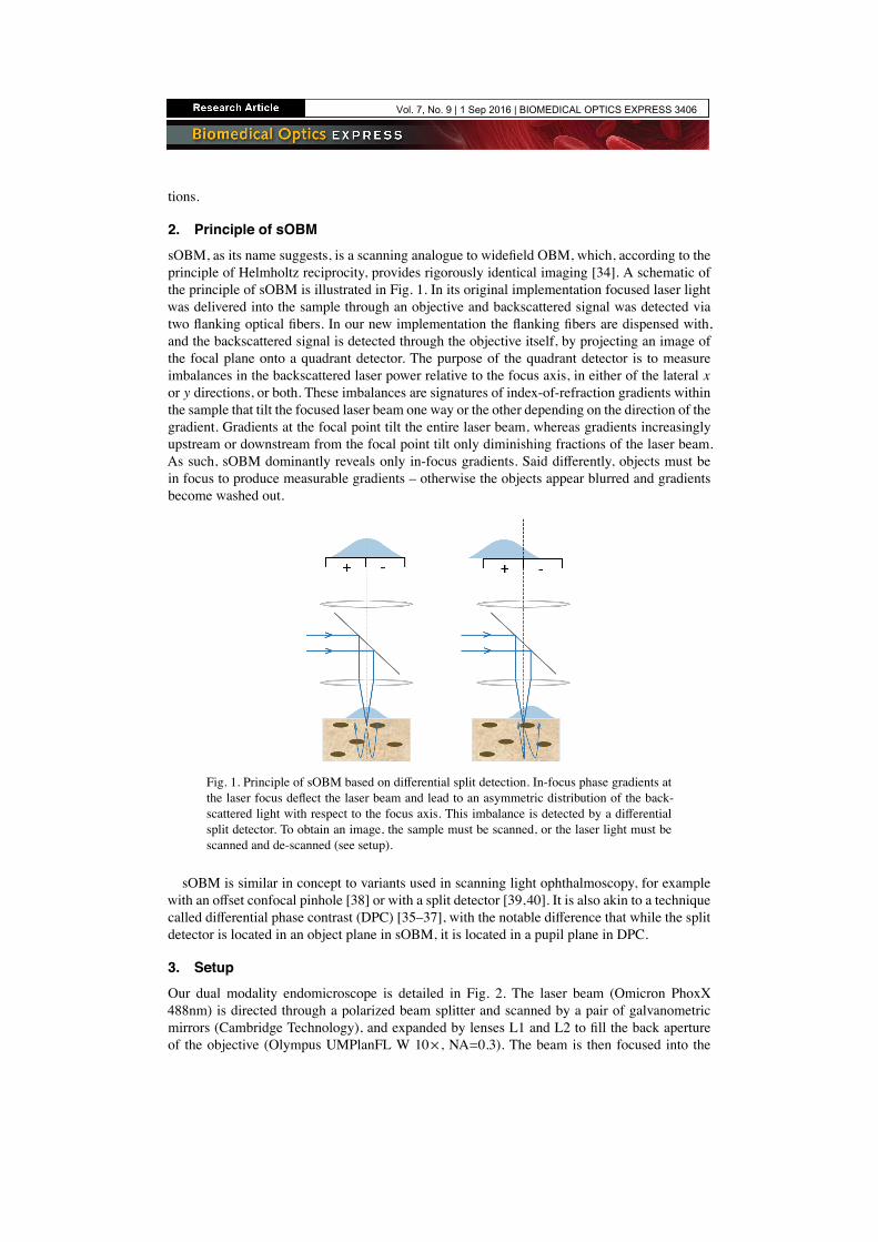
2. Principle of sOBMsOBM, as its name suggests, is a scanning analogue to widefield OBM, which, according to theprinciple of Helmholtz reciprocity, provides rigorously identical imaging [34]. A schematic ofthe principle of sOBM is illustrated in Fig. 1. In its original implementation focused laser lightwas delivered into the sample through an objective and backscattered signal was detected viatwo flanking optical fibers. In our new implementation the flanking fibers are dispensed with,and the backscattered signal is detected through the objective itself, by projecting an image ofthe focal plane onto a quadrant detector. The purpose of the quadrant detector is to measureimbalances in the backscattered laser power relative to the focus axis, in either of the lateral xor y directions, or both. These imbalances are signatures of index-of-refraction gradients withinthe sample that tilt the focused laser beam one way or the other depending on the direction of thegradient. Gradients at the focal point tilt the entire laser beam, whereas gradients increasinglyupstream or downstream from the focal point tilt only diminishing fractions of the laser beam.As such, sOBM dominantly reveals only in-focus gradients. Said differently, objects must bein focus to produce measurable gradients – otherwise the objects appear blurred and gradientsbecome washed out.
Fig. 1. Principle of sOBM based on differential split detection. In-focus phase gradients atthe laser focus deflect the laser beam and lead to an asymmetric distribution of the back-scattered light with respect to the focus axis. This imbalance is detected by a differentialsplit detector. To obtain an image, the sample must be scanned, or the laser light must bescanned and de-scanned (see setup).
sOBM is similar in concept to variants used in scanning light ophthalmoscopy, for examplewith an offset confocal pinhole [38] or with a split detector [39,40]. It is also akin to a techniquecalled differential phase contrast (DPC) [35–37], with the notable difference that while the splitdetector is located in an object plane in sOBM, it is located in a pupil plane in DPC.
3. SetupOur dual modality endomicroscope is detailed in Fig. 2. The laser beam (Omicron PhoxX488nm) is directed through a polarized beam splitter and scanned by a pair of galvanometricmirrors (Cambridge Technology), and expanded by lenses L1 and L2 to fill the back apertureof the objective (Olympus UMPlanFL W 10× , NA=0.3). The beam is then focused into the
Vol. 7, No. 9 | 1 Sep 2016 | BIOMEDICAL OPTICS EXPRESS 3406

proximal end of a flexible imaging fiber bundle, whereupon it is transmitted by individual fibercores. The fiber bundle itself consists of 30,000 cores, each approximately 1.9 µm in diameterseparated by an average distance of 3.3 µm (center to center). The total useful diameter of thefiber bundle is 600 µm. The distal end features a micro-objective (Mauna-Kea Technologies;2.6 mm diameter; 14 mm length; either 1× or 2.5× magnification; 60 µm working distance;NA=0.8 water). Both the fiber bundle and the micro-objective serve to relay the laser light intothe sample, producing a scanning focal spot of size roughly given by the core diameter dividedby the micro-objective magnification. Two signals can be produced by this laser focus. The firstis fluorescence, which is epi-collected by the micro-objective and relayed by the fiber bundleback into the microscope, whereupon it is de-scanned and relayed again into a pinhole (NationalAperture, 50µm), and detected through an emission filter by a photomultiplier tube (HamamatsuHC125-02). The net magnification from the microscope objective focal plane to the pinhole isabout 28× , meaning that the image of a single fiber core at the pinhole plane is about 53µm, orslightly larger than the pinhole diameter. The fluorescence is thus obtained in the same manneras a conventional scanning confocal microscope, similar to [12].
GM
10x
L1
L2FB
OBJ
L3
L4
PBS
L5RPEF
L6
μOBJ
PMT
+ -QD
L7LP
ND
Laser
FBFμμOOOBJ
Fig. 2. Schematic of our dual modality endomicroscope. PBS, polarized beam splitter;GM, galvanometric mirrors; OBJ, microscope objective; FB, fiber bundle; µOBJ, micro-objective; RP, reflective pinhole; EF, emission filter; PMT, photomultiplier tube; LP, linearpolarizer; ND, neutral density filter; QD, quadrant detector.
The second signal comes from the laser beam itself, or more precisely the portion of the beamthat traverses the focal plane and is redirected toward the sample surface by multiple scattering,in a confined enough region about the focus axis that it is collected by the micro-objective.This light is de-scanned and re-imaged onto the pinhole plane in the same manner as fluores-cence, but, unlike fluorescence, here we are interested in detecting only multiply backscatteredlight and not ballistic light (i.e. not singly backscattered light originating directly from the fo-cal point). In fact, the pinhole is reflective. The image of the multiply backscattered light isrelayed yet again onto a quadrant detector (SensL, MicroFC-60035-SMT 2×2, quadrant size:6mm), where differences between the left/right or top/bottom quadrants yield sOBM signalscorresponding to sample-induced phase gradients in the x or y directions. The net magnifica-tion from the microscope objective focal plane to the quadrant detector is 13× , meaning that theimage of the proximal face of fiber bundle at the quadrant detector is about 8 mm in diameter.An additional neutral density filter (OD=0.7) is inserted before the quadrant detector to ensure
Vol. 7, No. 9 | 1 Sep 2016 | BIOMEDICAL OPTICS EXPRESS 3407
this remains within its dynamic range.Some issues to consider. In particular, spurious background light can be detected by the
quadrant detector that can undermine the sOBM signal. This does not come from singly back-reflected light from the laser focus (i.e. what would normally be considered FCRM signal),because such light either goes through the pinhole or gets relayed to the 1mm gap between theSensL detector quadrants, and thus does not contribute to the sOBM image. By far, the most sig-nificant background comes instead from specular back-reflections originating from various op-tical interfaces in the illumination beam path. The most deleterious of these are back-reflectionsoriginating from the fiber probe, such as the interfaces at the proximal and distal ends of thefiber bundle (the former can be reduced by using an immersion objective), and interfaces withinthe probe micro-objective itself. To reduce these back-reflections as much as possible, we makeuse of two cross-polarizers (PBS and LP in Fig. 2). However this leads to only incomplete back-ground rejection because the polarization of distal back-reflections becomes mostly scrambledthrough the fiber bundle. Additional rejection must be performed numerically by first acquiringa background image (no sample) and then systematically subtracting this background from sub-sequent sOBM images. A similar background subtraction is also performed with fluorescenceimages to reduce spurious autofluorescence produced by the fiber-bundle.Finally, there is the problem of the patterned appearance of the images caused by the quasi-
periodic distribution of the fiber cores. To alleviate this, we applied an iterative segmentation-interpolation algorithm that basically fills in the gaps between the fiber cores. A detailed descrip-tion of this algorithm can be found in [41]. This algorithm has the advantages that it is fast (typ-ically 2-3 iterations suffice to produce adequate results) and does not sacrifice spatial resolutionor sample contrast, as opposed to, for example, Gaussian or median filtering. We note that thisalgorithm was initially designed for positive-only images, whereas sOBM produces both posi-tive and negative values. We thus modified our algorithm to apply segmentation-interpolationto the positive and negative components of the sOBM images separately.
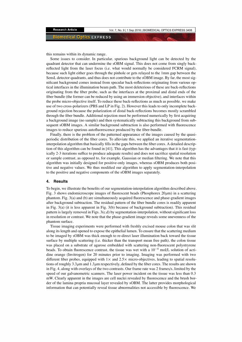
4. ResultsTo begin, we illustrate the benefits of our segmentation-interpolation algorithm described above.Fig. 3 shows endomicroscope images of fluorescent beads (Phosphorex 20µm) in a scatteringphantom. Fig. 3(a) and (b) are simultaneously acquired fluorescence and phase-gradient imagesafter background subtraction. The residual pattern of the fiber bundle cores is readily apparentin Fig. 3(a) (it is less apparent in Fig. 3(b) because of background subtraction). This residualpattern is largely removed in Figs. 3(c,d) by segmentation-interpolation, without significant lossin resolution or contrast. We note that the phase-gradient image reveals some unevenness of thephantom surface.Tissue imaging experiments were performed with freshly excised mouse colon that was slit
along its length and opened to expose the epithelial lumen. To ensure that the scattering mediumto be imaged by sOBM was thick enough to re-direct laser illumination back toward the tissuesurface by multiple scattering (i.e. thicker than the transport mean free path), the colon tissuewas placed on a substrate of agarose embedded with scattering non-fluorescent polystryrenebeads. To obtain fluorescence contrast, the tissue was wet with a 10−4 mol/L solution of acri-dine orange (Invitrogen) for 20 minutes prior to imaging. Imaging was performed with twodifferent fiber probes, equipped with 1× and 2.5× micro-objectives, leading to spatial resolu-tions of roughly 3.3µm and 1.3µm respectively, defined by the fiber cores. The results are shownin Fig. 4, along with overlays of the two contrasts. Our frame rate was 2 frames/s, limited by thespeed of our galvanometric scanners. The laser power incident on the tissue was less than 0.3mW. Clearly apparent in the images are cell nuclei revealed by fluorescence and the brush bor-der of the lamina propria mucosal layer revealed by sOBM. The latter provides morphologicalinformation that can potentially reveal tissue abnormalities not accessible by fluorescence. We
Vol. 7, No. 9 | 1 Sep 2016 | BIOMEDICAL OPTICS EXPRESS 3408
Before processingBefore processing
After processingAfter processing
Before processingBefore processing
After processingAfter processing
Fig. 3. Simultaneous fluorescence (left) and sOBM (right) images of 20µm beads in a scat-tering phantom, acquired with a 2.5× micro-objective. Top and bottom panels correspondto images before and after the application of segmentation-interpolation to remove pattern-ing artifacts due to the fiber bundle cores (scale bar 24µm).
emphasize again that the fluorescence and phase-gradient contrasts, while representing comple-mentary sample information, are automatically co-registered here because they arise from thesame laser focus.To evaluate the degradation of our images caused by the use of the fiber probe (i.e. the
micro-objective and fiber-bundle relay), we removed this and obtained images of the same tis-sue through the microscope objective alone (Olympus UPlanFL N 10× , NA=0.3), as shownin Fig. 5. These have the same FoV and can be directly compared with endomicroscope im-ages obtained through the 1× fiber probe. Despite the degradation in resolution and SNR (seediscussion) caused by the fiber probe, the images appear similar and reveal the same structures.
5. DiscussionIn summary, we have demonstrated, for the first time to our knowledge, a dual-modality en-domicroscope that produces simultaneous, co-registered fluorescence (CLE) and phase-gradient(sOBM) contrast, with the goal of laying some groundwork for a potential future clinical device.While successful, we note that our technique is not without drawbacks.The most egregious problem we faced came from the spurious back-reflected laser light origi-
nating from optical interfaces within our device, particularly the interfaces within the distal endof of the fiber probe. While we did our best to reject this background optically and reduce itnumerically, we were only moderately successful. For example, while background subtractionis indeed effective at reducing, or even eliminating, average background, it cannot reduce theshot noise associated with this background which can compromise SNR (we note that our ref-erence background image acquired with no sample was spatially filtered to avoid introducingeven more shot noise from the background image itself). However, it should be mentioned thatthe fiber probes used for our demonstrations were not designed with sOBM in mind. Perhapsfuture designs could incorporate improved anti-reflection coatings to minimize back-reflectionsat the laser wavelength, or, better yet, an integrated polarizer/quarter-wave-plate isolator.
Vol. 7, No. 9 | 1 Sep 2016 | BIOMEDICAL OPTICS EXPRESS 3409

Fig. 4. Top row from left to right: fluorescence, phase-gradient and combined images ofmouse colon tissue labeled with acridine orange, acquired with 2.5× micro-objective (scalebar 24µm). See also Visualization 1 for a video recorded with a frame rate of 2 fps. Bot-tom row from left to right, fluorescence, phase-gradient and combined images of the samesample acquired with 1× micro-objective (scale bar 60µm).
Fig. 5. From left to right: fluorescence, phase-gradient and combined images of labeledmouse colon tissue acquired directly through the microscope objective with no fiber probe(scale bar 60µm). These span the same FoV as the bottom row images in Fig. 4 and can beused to evaluate the degradation caused by the fiber probe. Also see Visualization 2 for avideo recorded with this setup.
Vol. 7, No. 9 | 1 Sep 2016 | BIOMEDICAL OPTICS EXPRESS 3410
Another difficulty we faced was that of limited depth penetration, which was restricted in ourcase by the 60µm working distance of our fiber probes. But even if this working distance hadbeen extended, we would have been faced with the inherent limitation of sOBM that it cannotpenetrate deeper than the scattering length of the laser illumination (same depth limitation asfor standard DIC). For mouse colon tissue illuminated by 488nm light, we estimated this tobe somewhere on the order of the probe working distance in any case. We also anticipate afew challenges when performing actual clinical imaging, such as probe stability and en-faceplacement, though these challenges are not new and seem to have been largely resolved incommercial instrumentation for gastro-enterological imaging [12].Finally, we close our paper with an interesting aside. It was emphasized above that OBM and
sOBM should produce rigorously identical images owing to the principle of Helmholtz reci-procity. But it was also noted that OBM, when operated with laser illumination (as opposed toLED illumination), produced unacceptable speckle noise. This speckle noise was mostly absentfrom our sOBM images, even though our sOBM was operated with laser illumination. Whywas that? This apparent discrepancy is resolved by noting that our OBM and sOBM configura-tions were, in fact, not exact reciprocal analogues. Ideal laser illumination corresponds to singlespatial-mode illumination. An exact reciprocal analogue sOBM would then have required sin-gle mode detection. But in our case, sOBM detection was performed with a large-area quadrantdetector, meaning our detection was highly multimode. Had we replaced our large-area quad-rant detector with four offset small pinholes, we would have indeed observed significant specklenoise, but as it happened this speckle noise was spatially averaged by our large-area detector soas to become effectively negligible.
FundingThis work was supported by NIH grants R01CA182939 and R21EB020851 and NSF grantCBET-1508988.
Vol. 7, No. 9 | 1 Sep 2016 | BIOMEDICAL OPTICS EXPRESS 3411