Embed Size (px)
Citation preview
Dual Strip Weaving: Interactive Design of Quad Layouts using Elastica Strips
Marcel Campen∗
RWTH Aachen University
Leif Kobbelt∗
RWTH Aachen University
Figure 1: Overview of our Dual Strip Weaving approach for the design of quadrilateral patch layouts. a) When hovering over the object, theuser is immediately presented with the best elastica strip (visualized using a stripe pattern) at the current pointer position. It can be selectedand fixed with a single click. b) Fixed strips (blue) constrain the design space; only compatible strips are offered next (green). c) Indicatorsbased on color-coding and stripe patterns guide the user to regions where modifications are recommended for the benefit of layout quality. d)Finally, the implied quad layout structure is derived from a collection of strips. The accompanying video shows the entire process.
a) b) c) d)
Abstract
We introduce Dual Strip Weaving, a novel concept for the interac-tive design of quad layouts, i.e. partitionings of freeform surfacesinto quadrilateral patch networks. In contrast to established toolsfor the design of quad layouts or subdivision base meshes, whichare often based on creating individual vertices, edges, and quads,our method takes a more global perspective, operating on a higherlevel of abstraction: the atomic operation of our method is the cre-ation of an entire cyclic strip, delineating a large number of quadpatches at once. The global consistency-preserving nature of thisapproach reduces demands on the user’s expertise by requiring lessadvance planning. Efficiency is achieved using a novel method atthe heart of our system, which automatically proposes geometri-cally and topologically suitable strips to the user. Based on thiswe provide interaction tools to influence the design process to anydesired degree and visual guides to support the user in this task.
CR Categories: I.3.5 [Computer Graphics]: Computational Ge-ometry and Object Modeling;
Keywords: quad mesh, base complex, segmentation, partition,subdivision, parameterization, edge flow
Links: DL PDF
(c) 2014 Marcel Campen, Leif Kobbelt. This is the authors’ version of the work.
It is posted here for your personal use. Not for redistribution. The definitive ver-
sion is published in Proceedings of the 2014 SIGGRAPH Asia Conference, ACM
Transactions on Graphics, Volume 33, Issue 6,
http://dx.doi.org/10.1145/2661229.2661236.
∗e-mail: (campen|kobbelt)@cs.rwth-aachen.de
1 Introduction
Since the early days of Computer-Aided Geometric Design, the par-titioning of a surface into (preferably few) quadrilateral patches (orconversely: its composition thereof) has been an essential requi-site and fundamental challenge. It is the tensor product nature ofsmooth surface representations like Bezier, B-Spline, or NURBSpatches that established the need for such structures. Especially forreverse engineering purposes, the efficient creation of such parti-tionings has always been an important challenge, as outlined by [Liet al. 2006]. Quad meshes, which have seen an increase in popu-larity in recent years, sparked new interest in this problem. This isdue to the fact that semi-regular quad meshes, which contain an un-derlying coarse quadrilateral base structure, i.e. which are a regularrefinement of a quad layout, provide advantages for various appli-cation cases, as detailed in a recent survey [Bommes et al. 2013a].
A number of methods that tackle (variants of) this problem in an au-tomatic manner have been proposed [Eck and Hoppe 1996; Boier-Martin et al. 2004; Dong et al. 2006; Daniels et al. 2009; Tariniet al. 2011; Bommes et al. 2011; Campen et al. 2012; Bommeset al. 2013b]. Suitability of these methods’ results depends on theapplication context. An inherent issue is that a good quad layoutgenerally is a compromise [Campen et al. 2012] that has to bal-ance coarseness, patch rectangularity, feature and principal curva-ture alignment, and possibly further objectives. The precise for-malization of the relative importances of these aspects and furtherrequirements and side conditions in a certain application context isnot an easy task, nor is automatically finding the optimal layout, as-suming such formal description and quality measure was available.
The field of quad mesh generation is related but essentially dif-ferent: in this field one typically aims for rather uniformly sizedand shaped quads instead of a coarse network of potentially non-uniform patches whose dimensions are rather implied by the ge-ometry and global structural interdependencies. Despite these dif-ferences, this field faces a very similar issue: a compromise be-
tween alignment, orientation, and element shape needs to be found[Bommes et al. 2009]. A solution which proved successful in prac-tice was the inclusion of the user in the process – instead of aimingfor full automation. Major 3D sculpting packages like Pixologic’sZBrush or Pilgway’s 3D-Coat have recently been equipped withquad remeshing features which follow this paradigm and rely onhigh-level user interaction, e.g. regarding the specification of align-ment and element sizing. This allows the user to tune the result tomeet the given requirements – even if no formal description thereof,or no specialized optimization method therefor is available.
Unfortunately, while methods for quad mesh generation allow foruser influence (regarding edge flow, irregular vertex configurations,element sizing, element anisotropy, etc.) [Bommes et al. 2009;Zhang et al. 2010; Kovacs et al. 2011], even though not always atinteractive rates, existing methods targeted at the problem of quadlayout generation (e.g. [Eck and Hoppe 1996; Boier-Martin et al.2004; Tarini et al. 2011; Campen et al. 2012]) neither are intendedfor nor provide means for adequate user interaction.
1.1 Contribution
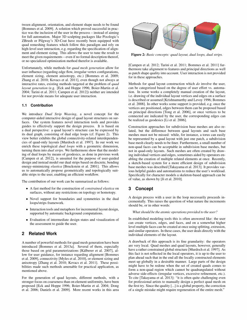
We introduce Dual Strip Weaving, a novel concept for thecomputer-aided interactive design of quad layout structures on sur-faces. Our system features novel interaction tools and providesguides to effectively support the design process. It is based ona dual perspective: a quad layout’s structure can be expressed byits dual graph, consisting of dual edge loops (cf. Figure 2). Thisview better exhibits the global connectivity-related interdependen-cies of quad-only layouts [Murdoch et al. 1997]. In our work weenrich these topological dual loops with a geometric dimension,turning them into dual strips. We furthermore show that the model-ing of dual loops by means of geodesics, as done in previous work[Campen et al. 2012], is unsuited for the purpose of user-guideddesign and instead model our dual strips based on discrete, bendingenergy-minimizing elastica [Bruckstein et al. 2001]. This allowsus to automatically propose geometrically and topologically suit-able strips to the user, enabling an efficient workflow.
The contribution of our work can be summarized as follows:
• A fast method for the construction of constrained elastica onsurfaces, without any restrictions on topology or homotopy.
• Novel support for boundaries and symmetries in the dualloops/strips framework.
• Interaction tools and metaphors for incremental layout design,supported by automatic background computations.
• Evaluation of intermediate design states and visualization ofthe assessment to guide the user.
2 Related Work
A number of powerful methods for quad mesh generation have beenintroduced [Bommes et al. 2013a]. Several of them, especiallythose based on grid parameterizations [Kalberer et al. 2007], al-low for user guidance, for instance regarding alignment [Bommeset al. 2009], connectivity [Myles et al. 2010], or element sizing andanisotropy [Zhang et al. 2010; Kovacs et al. 2011]. These possi-bilities made such methods amenable for practical application, asmentioned above.
For the generation of quad layouts, different methods, with astronger focus on coarseness than on element uniformity, have beenproposed [Eck and Hoppe 1996; Boier-Martin et al. 2004; Donget al. 2006; Daniels et al. 2009]. More recent works in this area
Figure 2: Basic concepts: quad layout, dual loops, dual strips.
[Campen et al. 2012; Tarini et al. 2011; Bommes et al. 2011] fur-thermore take alignment to features and principal directions as wellas patch shape quality into account. User interaction is not providedfor in these approaches.
Methods for quad layout construction which do involve the user,can be categorized based on the degree of user effort vs. automa-tion. In some works a completely manual creation of the layout,i.e. drawing of the individual layout vertices and edges on a surfaceis described or assumed [Krishnamurthy and Levoy 1996; Bommeset al. 2008]. In other works some support is provided, e.g. once thevertices are positioned, edges between them can be proposed basedon principal directions [Tong et al. 2006], or once vertices to beconnected are indicated by the user, the corresponding edges canbe realized as geodesics [Li et al. 2006].
Construction approaches for subdivision base meshes are also re-lated, but the difference between quad layouts and such basemeshes must not be missed: while, for instance, a torus can easilybe represented by a quad layout with just one patch, a subdivisionbase mesh clearly needs to be finer. Furthermore, a small number ofnon-quad faces can be acceptable in subdivision base meshes, butnot in quad-only layouts. Such meshes are often created by draw-ing individual vertices and edges, sometimes aided by operators en-abling the creation of multiple related elements at once. Recently,a sketch-based system for a more efficient design of subdivisionbase meshes was described [Takayama et al. 2013]. It provides var-ious helpful guides and automatisms to reduce the user’s workload.Specifically for character models a skeleton-based approach can beof value, as shown by [Ji et al. 2010].
3 Concept
A design process with a user in the loop necessarily proceeds in-crementally. This raises the question of what nature the incrementsshould be, or in other words:
What should be the atomic operations provided to the user?
In established modeling tools this is often answered like: the usercan create vertices, edges, and faces, and on a somewhat higherlevel multiple faces can be created at once using splitting, extrusion,and similar operators. In these cases, the user deals directly with theindividual elements of the layout.
A drawback of this approach is its fine granularity: the operatorsare very local. Quad meshes and quad layouts, however, generallyhave a rather constrained global structure [Murdoch et al. 1997]. Asthis fact is not reflected in the local operators, it is up to the user toplan ahead such that in the end all the locally constructed elementsmeet up globally in a desirable manner. Large parts of the designmight have to be redone when the set of created quads comes toform a non-quad region which cannot be quadrangulated withoutadverse side-effects (irregular vertices, excessive refinement, etc.).To cite [Takayama et al. 2013]: “it is often quite challenging evenfor professional artists to manually design a perfect quad mesh onthe first try. Since the quality [...] is a global property, the correctionof a single mistake might require regeneration of the entire mesh.”
Inspired by the work of [Campen et al. 2012], who used global dualloops for automatic quad layout construction, we propose to usethe creation of an entire dual strip as the atomic operation inour interactive design system. In contrast to the established localoperators, this operator has a kind of built-in global consistency(no non-quad patches are ever generated), effectively reducing theburden of “planning ahead” for the user.
3.1 Dual Strips
A dual loop corresponds to a cyclic chain of quads in the primallayout – cf. [Campen et al. 2012] for foundations and detailed def-initions. The union of all the quad patches of such chain we calldual strip, cf. Figure 2. We may say a dual loop is the spine of itsdual strip. Note that a quad patch of the primal layout correspondsto an intersection region of two dual strips, crossing transversally.From this point of view our goal of partitioning a surface into quadpatches is equivalent to doubly-covering the surface with dualstrips where all strip intersections are transversal.
A practical analogon which illustrates this idea is basketry, i.e. theweaving, or more specifically plaiting,of baskets from strips of plant materi-als like bark, straw, or flax. The figureon the left shows an example (courtesyof Jonas Hasselrot). Notice how everyquad is covered by two crossing strips.At the bottom corners of the basket itcan be observed that irregular “vertices”(here of valence 3) can be formed using
this technique, too. In this sense, the underlying conceptual idea ofour system can be seen as weaving dual strips on a given surface un-til it is covered. Note, though, that our strips are of variable widthand the layer-alternation of the woven strips, which serves stabil-ity in practice, is of no meaning in our case. This process of DualStrip Weaving is computationally supported in our system, e.g. byproposing optimal routes or choosing appropriate widths for strips.
Note that building the layout based on dual loops or strips does notrestrict the class of designable layouts in any way – for every quad-only layout there is an equivalent collection of dual loops/strips.
4 Interactive Workflow
We begin by describing the design workflow in order to provide ahigh-level understanding of the system and its core concepts. Theaccompanying video shows the system in action. As stated above,the creation of a dual strip is the fundamental operation in our sys-tem. Instead of having the user draw such strips by hand, the centralidea of our system is to compute suitably optimized dual strips au-tomatically and propose them to the user. Intuitive tools to select,edit, or model these strips are then made available to provide fullflexibility, while still keeping the user workload low. Technical de-tails of the involved algorithms for dual strip computation follow inSections 5 and 6.
4.1 Tools and Metaphors
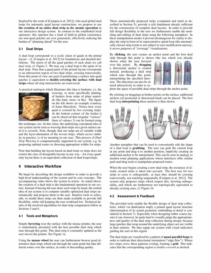
Simply hovering over the surface with the mouse pointer, the useris immediately presented with the best possible dual strip whichruns through this point. This dual strip is constantly updated as theuser moves the pointer. See Figure 1a.
Using the mouse wheel the user can furthermore browse good al-ternative dual strips which run through the same point but take dif-ferent routes over the surface, in order of descending quality.
These automatically proposed strips (computed and rated as de-scribed in Section 5), provide a rich fundament already sufficientfor the construction of complete dual layouts. In order to providefull design flexibility to the user we furthermore enable the mod-eling and editing of dual strips using the following metaphors. Inthese manipulation modes it proved advantageous for clarity to dis-play the strip in form of its representative spinal loop (the automati-cally chosen strip extent is not subject to user modification anyway;it serves purposes of “coverage” visualization).
By clicking, the user creates an anchor point and the best dualstrip through this point is shown (the one which was alreadyshown when the user hoveredover this point). By dragginga directional anchor is createdinstead, producing a dual stripwhich runs through this point,interpolating the specified direc-tion. The direction can also be al-tered interactively in order to ex-plore the space of possible dual strips through the anchor point.
By clicking (or dragging) at further points on the surface, additionalanchors (of positional or directional kind) can be placed. The bestdual loop interpolating these anchors is then shown.
Another metaphor that can be used to conveniently edit the shapeof a dual loop is grabbing. The user can grab the current loopat any point and drag it to another position, implicitly creating anadditional anchor to be interpolated. This can be seen in analogy tomodern route planning applications whose interfaces offer similargrab-and-drag tools to manipulate proposed routes.
When the user begins creating a new dual strip, the existence of al-ready created strips is taken into account. The best way for twostrips to cross is orthogonally; at least they should be crossingtransversally, not touching tangentially [Campen et al. 2012]. Thesystem only proposes strips which respect this, favoring orthogo-nality, and which are furthermore not topologically equivalent toalready existing ones, cf. Figure 1b.
4.2 Assessment & Feedback
The provided tools enable the flexible design of dual strip collec-tions, which via dualization imply a primal quad layout structure(determination of its actual geometric embedding in detail is con-sidered in Section 7). Especially when designing rather coarse lay-outs it can, however, be quite hard to visually judge the appropriate-ness and quality of the dual strip collection during design, becauselarge patches that wrap around the underlying object are not visiblein their entirety. We thus equip our system with visual indicatorsguiding the user in this regard.
The dual strips are visualized by a pattern of quasi-parallel loops inorder to indicate their directional orientation (“edge flow”). Wheretwo strips cross, these patterns overlap, forming a grid. This indi-cates that the corresponding region is doubly-covered as desired.
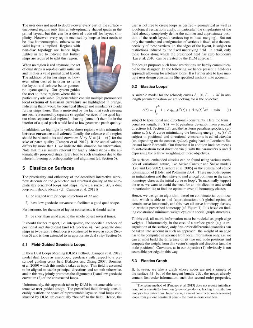
The user does not need to doubly-cover every part of the surface –uncovered regions only hint at sub-optimally shaped quads in theprimal layout, but this can be a desired trade-off for layout sim-plicity. However, every region enclosed by loops at least needs tobe disc-homeomorphic, otherwise novalid layout is implied. Regions withnon-disc topology are hence high-lighted in red to indicate that furtherstrips are required to split this region.
When no region is red anymore, the setof dual strips is topologically sufficientand implies a valid primal quad layout.The addition of further strips is, how-ever, often desired in order to refinethe layout and achieve better geomet-ric layout quality. Our system guidesthe user to those regions where this isparticularly advisable. Regions which contain multiple pronouncedlocal extrema of Gaussian curvature are highlighted in orange,indicating that it would be beneficial (though not mandatory) to addfurther strips there. This is motivated by the fact that such extremaare best represented by separate (irregular) vertices of the quad lay-out (thus separate dual regions) – having (some of) them lie in theinterior of a quad patch would lead to low geometric patch quality.
In addition, we highlight in yellow those regions with a mismatchbetween curvature and valence: Ideally, the valence v of a regionshould be related to its total curvature K by K = (4 − v)π
2for the
sake of patch quality [Campen et al. 2012]. If the actual valencediffers by more than 1, we indicate this situation for information.Note that this is mainly relevant for highly edited strips – the au-tomatically proposed strips rarely lead to such situations due to theinherent favoring of orthogonality and alignment (cf. Section 5).
5 Elastica on Surfaces
The practicality and efficiency of the described interactive work-flow depends on the geometric and structural quality of the auto-matically generated loops and strips. Given a surface M , a dualloop on it should ideally (cf. [Campen et al. 2012])
1) be aligned with principal directions of M and
2) have low geodesic curvature to facilitate a good quad shape.
Furthermore, for the sake of layout coarseness, it should rather
3) be short than wind around the whole object several times.
It should further respect, i.e. interpolate, the specified anchors ofpositional and directional kind (cf. Section 4). We generate dualstrips in two steps: a dual loop is constructed to serve as spine (Sec-tion 5) and is then extended to an appropriate dual strip (Section 6).
5.1 Field-Guided Geodesic Loops
In their Dual Loops Meshing (DLM) method, [Campen et al. 2012]model dual loops as anisotropic geodesics with respect to a pre-scribed guiding cross field [Palacios and Zhang 2007; Bommeset al. 2009] which this method takes as input. This field is assumedto be aligned to stable principal directions and smooth otherwise,and in this way jointly promotes the alignment (1) and low geodesiccurvature (2) of the constructed loops.
Unfortunately, this approach taken by DLM is not amenable to in-teractive user-guided design. The prescribed field already consid-erably restricts the space of representable layouts: dual loops con-structed by DLM are essentially “bound” to the field. Hence, the
user is not free to create loops as desired – geometrical as well astopological restrictions apply. In particular, the singularities of thefield already completely define the number and approximate posi-tion of the result layout’s vertices (up to local merging). But notonly the number and configuration of vertices is fixed, also the con-nectivity of these vertices, i.e. the edges of the layout, is subject torestrictions induced by the fixed underlying field. In detail, onlythose loops along which the prescribed field has zero holonomy[Lai et al. 2010] can be created by the DLM approach.
For design purposes such broad restrictions are hardly communica-ble to the designer. In the following we hence present a field-lessapproach allowing for arbitrary loops. It is further able to take mul-tiple user design constraints (the specified anchors) into account.
5.2 Elastica Loops
A suitable model for the (closed) curves ℓ : [0, L] → M in arc-length parameterization we are looking for is the objective
c(ℓ) =
Z L
0
1 + α qℓ(t)(ℓ′(t)) + β κℓ(t)
2dt→ min (1)
subject to (positional and directional) constraints. Here the term 1penalizes length, q : TM → R penalizes deviation from principaldirections (cf. Section 5.5), and the last term penalizes geodesic cur-vature κℓ(t). A curve minimizing the bending energy
R
κℓ(t)2dt
subject to positional and directional constraints is called elastica(or, depending on the context, spline), going back to Leonhard Eu-ler and Jacob Bernoulli. Our functional in addition includes meansto soft-constrain local direction via q, with the parameters α and βexpressing the relative weighting of these objectives.
On surfaces, embedded elastica can be found using various meth-ods of variational nature, like Active Contour and Snake models[Lee and Lee 2002; Bischoff et al. 2005] or the constrained splineoptimization of [Hofer and Pottmann 2004]. These methods requirean initialization and then strive to find a local optimum in the samehomotopy class as the initial curve or loop1. To maximally supportthe user, we want to avoid the need for an initialization and wouldin particular like to find the optimum over all homotopy classes.
Hence, we design an algorithm, based on combinatorial optimiza-tion, which is able to find (approximations of) global optima ofcertain curve functionals, and this over all curve homotopy classes,i.e. without prescribed homotopy (cf. Figure 3). It is based on find-ing constrained minimum weight cycles in special graph structures.
To this end, all metric information must be modeled as graph edgeweights. Unfortunately, in the case of a surface graph (e.g. a tri-angulation of the surface) only first-order differential quantities canbe taken into account in such an approach: the weight of an edgehas to be computed in advance from local information only, i.e. wecan at most build the difference of its two end node positions andcompute the weight from this vector’s length and direction (and thenode positions). Curvature, as in our objective (1), obviously is notaccessible per-edge in this way.
5.3 Elastica Graph
If, however, we take a graph whose nodes are not a sample ofthe surface M , but of the tangent bundle TM , the nodes alreadycontain first-order information, such that second-order properties,
1The spline method of [Panozzo et al. 2013] does not require initializa-
tion, but is essentially based on (pseudo-)geodesics, leading to similar ho-
motopy class restrictions. In particular, it cannot construct (non-degenerate)
loops from just one constraint point – the most relevant case here.
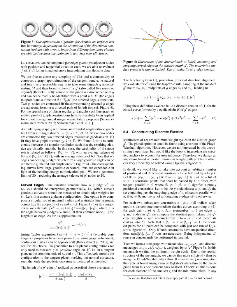
Figure 3: Our optimization algorithm for elastica on surfaces hasfree homotopy: depending on the orientation of the directional con-straint (red dot with arrow), loops from differing homotopy classesare obtained because the optimum is searched over all classes.
i.e. curvature, can be computed per edge: given two adjacent nodeswith position and tangential direction each, we are able to evaluateR
κ(t)2dt for an imagined curve interpolating this Hermite data.
We are free to chose any sampling of TM and a connectivity toconstruct a graph approximation of the tangent bundle. A naturaland intuitively accessible way is to take some digraph g approxi-mating M and then form its derivative g′ (also called line graph oradjoint) [Beineke 1968]: a node of this graph is a directed edge of gand can hence readily be identified with a point p ∈ M (the edge’smidpoint) and a direction d ∈ TpM (the directed edge’s direction).Two g′-nodes are connected iff the corresponding directed g-edgesare adjacent, forming a directed path of length two (cf. Figure 4).For the special case of planar regular grid graphs such line graph orrelated product graph constructions have successfully been appliedfor curvature-regularized image segmentation purposes [Schoene-mann and Cremers 2007; Schoenemann et al. 2011].
As underlying graph g we choose an extended neighborhood graphbuilt from a triangulation T = (V,E, F ) of M , where two nodesare connected (by two directed edges, realized as geodesics on M )iff they have graph distance ≤ k in T . We found k = 4 to suffi-ciently increase the angular resolution such that the resulting elas-tica are visually smooth. In this case, the cardinality of the nodesets is related as follows: |Vg| = |V |, with an average valence of60, and |Vg′ | ≈ 60|V |, with an average valence of 60. Note that g′-edges connecting g-edges which form a large geodesic angle can beomitted (e.g. the red and purple ones in Figure 4) – the correspond-ing curves have large geodesic curvature, thus are expendable inlight of the bending energy minimization goal. We use a generouslimit of 30◦, reducing the average valence of g′-nodes to 10.
Curved Edges The question remains how a g′-edge e′ =(e0, e1) should be interpreted geometrically, i.e. which curve’sgeodesic curvature should be measured to obtain edge weights fore′. Let’s first assume a planar configuration. One option is to com-pose a circular arc of maximal radius and a straight line segment,connecting the midpoints of e0 and e1 (cf. Figure 4). For this uniquecurve we calculate
R
κ2 = 2γ tan γ
2/min(|e0|, |e1|), where γ is
the angle between g-edges e0 and e1 at their common node, | · | thelength of an edge. As for its approximation
γ2
min(|e0|, |e1|)=: κ2(e′)
(using Taylor expansion tan(γ) = γ + O(γ3)) favorable con-vergence properties have been proved (i.e. using graph refinement,continuous elastica can be approached) [Bruckstein et al. 2001], weopt for this choice. To generalize to non-planar configurations weonly need to measure γ as geodesic angle on M , i.e. in a tangentplane at the common node of e0 and e1. This effectively unrolls theconfiguration to the tangent plane, masking out normal curvature,such that only the geodesic curvature is measured as intended.
The length of a g′-edge e′ realized as described above evaluates to
|e′| =γmin(|e0|, |e1|)
2 tan γ
2
+||e0| − |e1||
2.
Figure 4: Illustration of one directed node’s (black) incoming andoutgoing curved edges in the elastica graph g′. The underlying sur-face graph g is shown dashed. The g′-nodes lie at g-edge centers.
The function q from (1), promoting principal direction alignment,we evaluate for e′ using the trapezoid rule, sampling at the incidentg′-nodes n0, n1 (midpoints of g-edges e0 and e1), leading to
q(e′) :=1
2(qn0
(e0) + qn1(e1)) |e
′|.
Using these definitions we can build a discrete version of (1) for theclosed curve formed by a cyclic chain E of g′-edges:
c(E) =X
e′∈E
|e′| + α q(e′) + β κ2(e′) =:X
e′∈E
w(e′) (2)
5.4 Constructing Discrete Elastica
Minimizers of (2) are minimum weight cycles in the elastica graphg′. The global optimum could be found using a variant of the Floyd-Warshall algorithm. However, we are not interested in this uncon-strained optimizer, but would like the loop to interpolate the speci-fied anchors to account for user influence. Therefore, we design analgorithm based on nested minimum weight path problems whichcan very efficiently be solved using Dijkstra’s algorithm.
In detail, we would like to take into account an arbitrary numberof positional and directional constraints to be fulfilled by a loop ℓ.Let Φ = (φ0, . . . , φn−1) with φi = (pi, di) ∈ TM be a list ofn > 0 constraint points that shall be passed by ℓ in order, withtangent parallel to di where di 6= 0 (di = 0 signifies a purelypositional constraint). Let vi be the g-node closest to pi and ξi theset containing just the outgoing g-edge of vi closest to parallel withdi if di 6= 0, and the set of all outgoing g-edges of vi otherwise.
For each two subsequent constraints φi, φi+1 (all indices takenmod n), we compute intermediate elastica curves according to (2):for each pair (a, b) ∈ ξi × ξi+1 (remember: a, b are edges ing and nodes in g′) we compute the shortest path (taking the g′-edge weights w into account) from a to b in g′ and record itscost as w(a, b). Note that if |ξi| = 1 or |ξi+1| = 1, the short-est paths for all pairs can be computed with just one run of Dijk-stra’s algorithm2. Only if both constraints have unspecified direc-tion, min(|ξi|, |ξi+1|) runs are necessary. Being independent, allruns can conveniently be performed in parallel.
Then we form a metagraph with metanodes ∪0≤i<nξi, and directedmetaedges ∪0≤i<n(ξi×ξi+1), weighted by w (cf. Figure 5). In thismetagraph we find the minimum-weight cycle. Due to the specialstructure of the metagraph, we can do this more efficiently than byusing the Floyd-Warshall algorithm. If at least one ξ is a singleton,the cycle is found using a run of Dijkstra’s algorithm on the meta-graph from this one element back to itself. Otherwise, this is donefor each element of the smallest ξ and the minimum taken. In any
2A variant that does not return the empty path if a = b must be used.
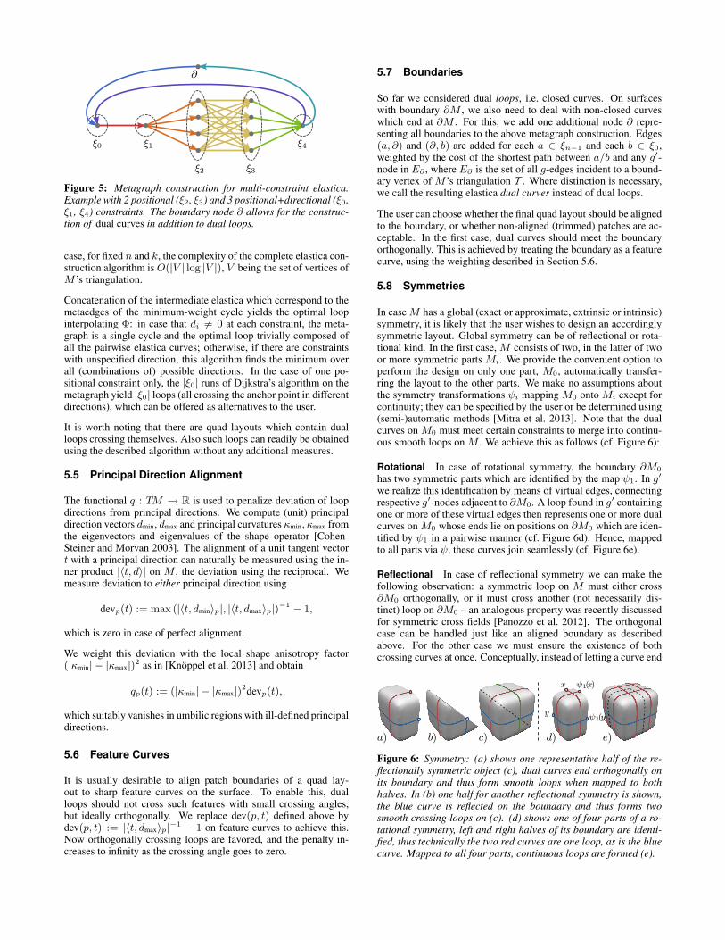
ξ0 ξ1
ξ2 ξ3
ξ4
∂
Figure 5: Metagraph construction for multi-constraint elastica.Example with 2 positional (ξ2, ξ3) and 3 positional+directional (ξ0,ξ1, ξ4) constraints. The boundary node ∂ allows for the construc-tion of dual curves in addition to dual loops.
case, for fixed n and k, the complexity of the complete elastica con-struction algorithm isO(|V | log |V |), V being the set of vertices ofM ’s triangulation.
Concatenation of the intermediate elastica which correspond to themetaedges of the minimum-weight cycle yields the optimal loopinterpolating Φ: in case that di 6= 0 at each constraint, the meta-graph is a single cycle and the optimal loop trivially composed ofall the pairwise elastica curves; otherwise, if there are constraintswith unspecified direction, this algorithm finds the minimum overall (combinations of) possible directions. In the case of one po-sitional constraint only, the |ξ0| runs of Dijkstra’s algorithm on themetagraph yield |ξ0| loops (all crossing the anchor point in differentdirections), which can be offered as alternatives to the user.
It is worth noting that there are quad layouts which contain dualloops crossing themselves. Also such loops can readily be obtainedusing the described algorithm without any additional measures.
5.5 Principal Direction Alignment
The functional q : TM → R is used to penalize deviation of loopdirections from principal directions. We compute (unit) principaldirection vectors dmin, dmax and principal curvatures κmin, κmax fromthe eigenvectors and eigenvalues of the shape operator [Cohen-Steiner and Morvan 2003]. The alignment of a unit tangent vectort with a principal direction can naturally be measured using the in-ner product |〈t, d〉| on M , the deviation using the reciprocal. Wemeasure deviation to either principal direction using
devp(t) := max (|〈t, dmin〉p|, |〈t, dmax〉p|)−1 − 1,
which is zero in case of perfect alignment.
We weight this deviation with the local shape anisotropy factor(|κmin| − |κmax|)
2 as in [Knoppel et al. 2013] and obtain
qp(t) := (|κmin| − |κmax|)2devp(t),
which suitably vanishes in umbilic regions with ill-defined principaldirections.
5.6 Feature Curves
It is usually desirable to align patch boundaries of a quad lay-out to sharp feature curves on the surface. To enable this, dualloops should not cross such features with small crossing angles,but ideally orthogonally. We replace dev(p, t) defined above bydev(p, t) := |〈t, dmax〉p|
−1 − 1 on feature curves to achieve this.Now orthogonally crossing loops are favored, and the penalty in-creases to infinity as the crossing angle goes to zero.
5.7 Boundaries
So far we considered dual loops, i.e. closed curves. On surfaceswith boundary ∂M , we also need to deal with non-closed curveswhich end at ∂M . For this, we add one additional node ∂ repre-senting all boundaries to the above metagraph construction. Edges(a, ∂) and (∂, b) are added for each a ∈ ξn−1 and each b ∈ ξ0,weighted by the cost of the shortest path between a/b and any g′-node in E∂ , where E∂ is the set of all g-edges incident to a bound-ary vertex of M ’s triangulation T . Where distinction is necessary,we call the resulting elastica dual curves instead of dual loops.
The user can choose whether the final quad layout should be alignedto the boundary, or whether non-aligned (trimmed) patches are ac-ceptable. In the first case, dual curves should meet the boundaryorthogonally. This is achieved by treating the boundary as a featurecurve, using the weighting described in Section 5.6.
5.8 Symmetries
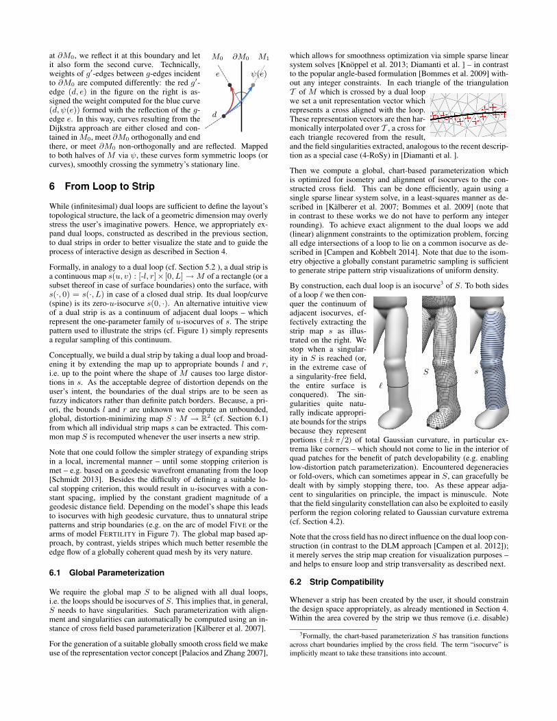
In caseM has a global (exact or approximate, extrinsic or intrinsic)symmetry, it is likely that the user wishes to design an accordinglysymmetric layout. Global symmetry can be of reflectional or rota-tional kind. In the first case, M consists of two, in the latter of twoor more symmetric parts Mi. We provide the convenient option toperform the design on only one part, M0, automatically transfer-ring the layout to the other parts. We make no assumptions aboutthe symmetry transformations ψi mapping M0 onto Mi except forcontinuity; they can be specified by the user or be determined using(semi-)automatic methods [Mitra et al. 2013]. Note that the dualcurves on M0 must meet certain constraints to merge into continu-ous smooth loops on M . We achieve this as follows (cf. Figure 6):
Rotational In case of rotational symmetry, the boundary ∂M0
has two symmetric parts which are identified by the map ψ1. In g′
we realize this identification by means of virtual edges, connectingrespective g′-nodes adjacent to ∂M0. A loop found in g′ containingone or more of these virtual edges then represents one or more dualcurves on M0 whose ends lie on positions on ∂M0 which are iden-tified by ψ1 in a pairwise manner (cf. Figure 6d). Hence, mappedto all parts via ψ, these curves join seamlessly (cf. Figure 6e).
Reflectional In case of reflectional symmetry we can make thefollowing observation: a symmetric loop on M must either cross∂M0 orthogonally, or it must cross another (not necessarily dis-tinct) loop on ∂M0 – an analogous property was recently discussedfor symmetric cross fields [Panozzo et al. 2012]. The orthogonalcase can be handled just like an aligned boundary as describedabove. For the other case we must ensure the existence of bothcrossing curves at once. Conceptually, instead of letting a curve end
a) b) c) d) e)
x ψ1(x)
yψ1(y)
Figure 6: Symmetry: (a) shows one representative half of the re-flectionally symmetric object (c), dual curves end orthogonally onits boundary and thus form smooth loops when mapped to bothhalves. In (b) one half for another reflectional symmetry is shown,the blue curve is reflected on the boundary and thus forms twosmooth crossing loops on (c). (d) shows one of four parts of a ro-tational symmetry, left and right halves of its boundary are identi-fied, thus technically the two red curves are one loop, as is the bluecurve. Mapped to all four parts, continuous loops are formed (e).
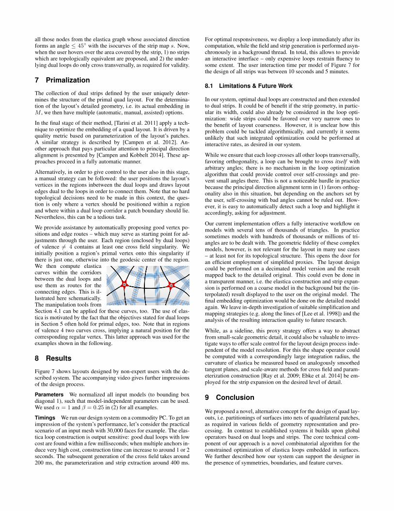
∂M0M0 M1
e
d
ψ(e)
at ∂M0, we reflect it at this boundary and letit also form the second curve. Technically,weights of g′-edges between g-edges incidentto ∂M0 are computed differently: the red g′-edge (d, e) in the figure on the right is as-signed the weight computed for the blue curve(d, ψ(e)) formed with the reflection of the g-edge e. In this way, curves resulting from theDijkstra approach are either closed and con-tained inM0, meet ∂M0 orthogonally and endthere, or meet ∂M0 non-orthogonally and are reflected. Mappedto both halves of M via ψ, these curves form symmetric loops (orcurves), smoothly crossing the symmetry’s stationary line.
6 From Loop to Strip
While (infinitesimal) dual loops are sufficient to define the layout’stopological structure, the lack of a geometric dimension may overlystress the user’s imaginative powers. Hence, we appropriately ex-pand dual loops, constructed as described in the previous section,to dual strips in order to better visualize the state and to guide theprocess of interactive design as described in Section 4.
Formally, in analogy to a dual loop (cf. Section 5.2 ), a dual strip isa continuous map s(u, v) : [-l, r]× [0, L] →M of a rectangle (or asubset thereof in case of surface boundaries) onto the surface, withs(·, 0) = s(·, L) in case of a closed dual strip. Its dual loop/curve(spine) is its zero-u-isocurve s(0, ·). An alternative intuitive viewof a dual strip is as a continuum of adjacent dual loops – whichrepresent the one-parameter family of u-isocurves of s. The stripepattern used to illustrate the strips (cf. Figure 1) simply representsa regular sampling of this continuum.
Conceptually, we build a dual strip by taking a dual loop and broad-ening it by extending the map up to appropriate bounds l and r,i.e. up to the point where the shape of M causes too large distor-tions in s. As the acceptable degree of distortion depends on theuser’s intent, the boundaries of the dual strips are to be seen asfuzzy indicators rather than definite patch borders. Because, a pri-ori, the bounds l and r are unknown we compute an unbounded,global, distortion-minimizing map S : M → R
2 (cf. Section 6.1)from which all individual strip maps s can be extracted. This com-mon map S is recomputed whenever the user inserts a new strip.
Note that one could follow the simpler strategy of expanding stripsin a local, incremental manner – until some stopping criterion ismet – e.g. based on a geodesic wavefront emanating from the loop[Schmidt 2013]. Besides the difficulty of defining a suitable lo-cal stopping criterion, this would result in u-isocurves with a con-stant spacing, implied by the constant gradient magnitude of ageodesic distance field. Depending on the model’s shape this leadsto isocurves with high geodesic curvature, thus to unnatural stripepatterns and strip boundaries (e.g. on the arc of model FIVE or thearms of model FERTILITY in Figure 7). The global map based ap-proach, by contrast, yields stripes which much better resemble theedge flow of a globally coherent quad mesh by its very nature.
6.1 Global Parameterization
We require the global map S to be aligned with all dual loops,i.e. the loops should be isocurves of S. This implies that, in general,S needs to have singularities. Such parameterization with align-ment and singularities can automatically be computed using an in-stance of cross field based parameterization [Kalberer et al. 2007].
For the generation of a suitable globally smooth cross field we makeuse of the representation vector concept [Palacios and Zhang 2007],
which allows for smoothness optimization via simple sparse linearsystem solves [Knoppel et al. 2013; Diamanti et al. ] – in contrastto the popular angle-based formulation [Bommes et al. 2009] with-out any integer constraints. In each triangle of the triangulationT of M which is crossed by a dual loopwe set a unit representation vector whichrepresents a cross aligned with the loop.These representation vectors are then har-monically interpolated over T , a cross foreach triangle recovered from the result,and the field singularities extracted, analogous to the recent descrip-tion as a special case (4-RoSy) in [Diamanti et al. ].
Then we compute a global, chart-based parameterization whichis optimized for isometry and alignment of isocurves to the con-structed cross field. This can be done efficiently, again using asingle sparse linear system solve, in a least-squares manner as de-scribed in [Kalberer et al. 2007; Bommes et al. 2009] (note thatin contrast to these works we do not have to perform any integerrounding). To achieve exact alignment to the dual loops we add(linear) alignment constraints to the optimization problem, forcingall edge intersections of a loop to lie on a common isocurve as de-scribed in [Campen and Kobbelt 2014]. Note that due to the isom-etry objective a globally constant parametric sampling is sufficientto generate stripe pattern strip visualizations of uniform density.
By construction, each dual loop is an isocurve3 of S. To both sides
sS
ℓ
of a loop ℓwe then con-quer the continuum ofadjacent isocurves, ef-fectively extracting thestrip map s as illus-trated on the right. Westop when a singular-ity in S is reached (or,in the extreme case ofa singularity-free field,the entire surface isconquered). The sin-gularities quite natu-rally indicate appropri-ate bounds for the stripsbecause they representportions (±k π/2) of total Gaussian curvature, in particular ex-trema like corners – which should not come to lie in the interior ofquad patches for the benefit of patch developability (e.g. enablinglow-distortion patch parameterization). Encountered degeneraciesor fold-overs, which can sometimes appear in S, can gracefully bedealt with by simply stopping there, too. As these appear adja-cent to singularities on principle, the impact is minuscule. Notethat the field singularity constellation can also be exploited to easilyperform the region coloring related to Gaussian curvature extrema(cf. Section 4.2).
Note that the cross field has no direct influence on the dual loop con-struction (in contrast to the DLM approach [Campen et al. 2012]);it merely serves the strip map creation for visualization purposes –and helps to ensure loop and strip transversality as described next.
6.2 Strip Compatibility
Whenever a strip has been created by the user, it should constrainthe design space appropriately, as already mentioned in Section 4.Within the area covered by the strip we thus remove (i.e. disable)
3Formally, the chart-based parameterization S has transition functions
across chart boundaries implied by the cross field. The term “isocurve” is
implicitly meant to take these transitions into account.
all those nodes from the elastica graph whose associated directionforms an angle ≤ 45◦ with the isocurves of the strip map s. Now,when the user hovers over the area covered by the strip, 1) no stripswhich are topologically equivalent are proposed, and 2) the under-lying dual loops do only cross transversally, as required for validity.
7 Primalization
The collection of dual strips defined by the user uniquely deter-mines the structure of the primal quad layout. For the determina-tion of the layout’s detailed geometry, i.e. its actual embedding inM , we then have multiple (automatic, manual, assisted) options.
In the final stage of their method, [Tarini et al. 2011] apply a tech-nique to optimize the embedding of a quad layout. It is driven by aquality metric based on parameterization of the layout’s patches.A similar strategy is described by [Campen et al. 2012]. An-other approach that pays particular attention to principal directionalignment is presented by [Campen and Kobbelt 2014]. These ap-proaches proceed in a fully automatic manner.
Alternatively, in order to give control to the user also in this stage,a manual strategy can be followed: the user positions the layout’svertices in the regions inbetween the dual loops and draws layoutedges dual to the loops in order to connect them. Note that no hardtopological decisions need to be made in this context, the ques-tion is only where a vertex should be positioned within a regionand where within a dual loop corridor a patch boundary should lie.Nevertheless, this can be a tedious task.
We provide assistance by automatically proposing good vertex po-sitions and edge routes – which may serve as starting point for ad-justments through the user. Each region (enclosed by dual loops)of valence 6= 4 contains at least one cross field singularity. Weinitially position a region’s primal vertex onto this singularity ifthere is just one, otherwise into the geodesic center of the region.We then compute elasticacurves within the corridorsbetween the dual loops anduse them as routes for theconnecting edges. This is il-lustrated here schematically.The manipulation tools fromSection 4.1 can be applied for these curves, too. The use of elas-tica is motivated by the fact that the objectives stated for dual loopsin Section 5 often hold for primal edges, too. Note that in regionsof valence 4 two curves cross, implying a natural position for thecorresponding regular vertex. This latter approach was used for theexamples shown in the following.
8 Results
Figure 7 shows layouts designed by non-expert users with the de-scribed system. The accompanying video gives further impressionsof the design process.
Parameters We normalized all input models (to bounding boxdiagonal 1), such that model-independent parameters can be used.We used α = 1 and β = 0.25 in (2) for all examples.
Timings We run our design system on a commodity PC. To get animpression of the system’s performance, let’s consider the practicalscenario of an input mesh with 30,000 faces for example. The elas-tica loop construction is output sensitive: good dual loops with lowcost are found within a few milliseconds; when multiple anchors in-duce very high cost, construction time can increase to around 1 or 2seconds. The subsequent generation of the cross field takes around200 ms, the parameterization and strip extraction around 400 ms.
For optimal responsiveness, we display a loop immediately after itscomputation, while the field and strip generation is performed asyn-chronously in a background thread. In total, this allows to providean interactive interface – only expensive loops restrain fluency tosome extent. The user interaction time per model of Figure 7 forthe design of all strips was between 10 seconds and 5 minutes.
8.1 Limitations & Future Work
In our system, optimal dual loops are constructed and then extendedto dual strips. It could be of benefit if the strip geometry, in partic-ular its width, could also already be considered in the loop opti-mization: wide strips could be favored over very narrow ones tothe benefit of layout coarseness. However, it is unclear how thisproblem could be tackled algorithmically, and currently it seemsunlikely that such integrated optimization could be performed atinteractive rates, as desired in our system.
While we ensure that each loop crosses all other loops transversally,favoring orthogonality, a loop can be brought to cross itself witharbitrary angles; there is no mechanism in the loop optimizationalgorithm that could provide control over self-crossings and pre-vent small angles there. This is not a noticeable hurdle in practicebecause the principal direction alignment term in (1) favors orthog-onality also in this situation, but depending on the anchors set bythe user, self-crossing with bad angles cannot be ruled out. How-ever, it is easy to automatically detect such a loop and highlight itaccordingly, asking for adjustment.
Our current implementation offers a fully interactive workflow onmodels with several tens of thousands of triangles. In practicesometimes models with hundreds of thousands or millions of tri-angles are to be dealt with. The geometric fidelity of these complexmodels, however, is not relevant for the layout in many use cases– at least not for its topological structure. This opens the door foran efficient employment of simplified proxies. The layout designcould be performed on a decimated model version and the resultmapped back to the detailed original. This could even be done ina transparent manner, i.e. the elastica construction and strip expan-sion is performed on a coarse model in the background but the (in-terpolated) result displayed to the user on the original model. Thefinal embedding optimization would be done on the detailed modelagain. We leave in-depth investigation of suitable simplification andmapping strategies (e.g. along the lines of [Lee et al. 1998]) and theanalysis of the resulting interaction quality to future research.
While, as a sideline, this proxy strategy offers a way to abstractfrom small-scale geometric detail, it could also be valuable to inves-tigate ways to offer scale control for the layout design process inde-pendent of the model resolution. For this the shape operator couldbe computed with a correspondingly large integration radius, thecurvature of elastica be measured based on analogously smoothedtangent planes, and scale-aware methods for cross field and param-eterization construction [Ray et al. 2009; Ebke et al. 2014] be em-ployed for the strip expansion on the desired level of detail.
9 Conclusion
We proposed a novel, alternative concept for the design of quad lay-outs, i.e. partitionings of surfaces into nets of quadrilateral patches,as required in various fields of geometry representation and pro-cessing. In contrast to established systems it builds upon globaloperators based on dual loops and strips. The core technical com-ponent of our approach is a novel combinatorial algorithm for theconstrained optimization of elastica loops embedded in surfaces.We further described how our system can support the designer inthe presence of symmetries, boundaries, and feature curves.
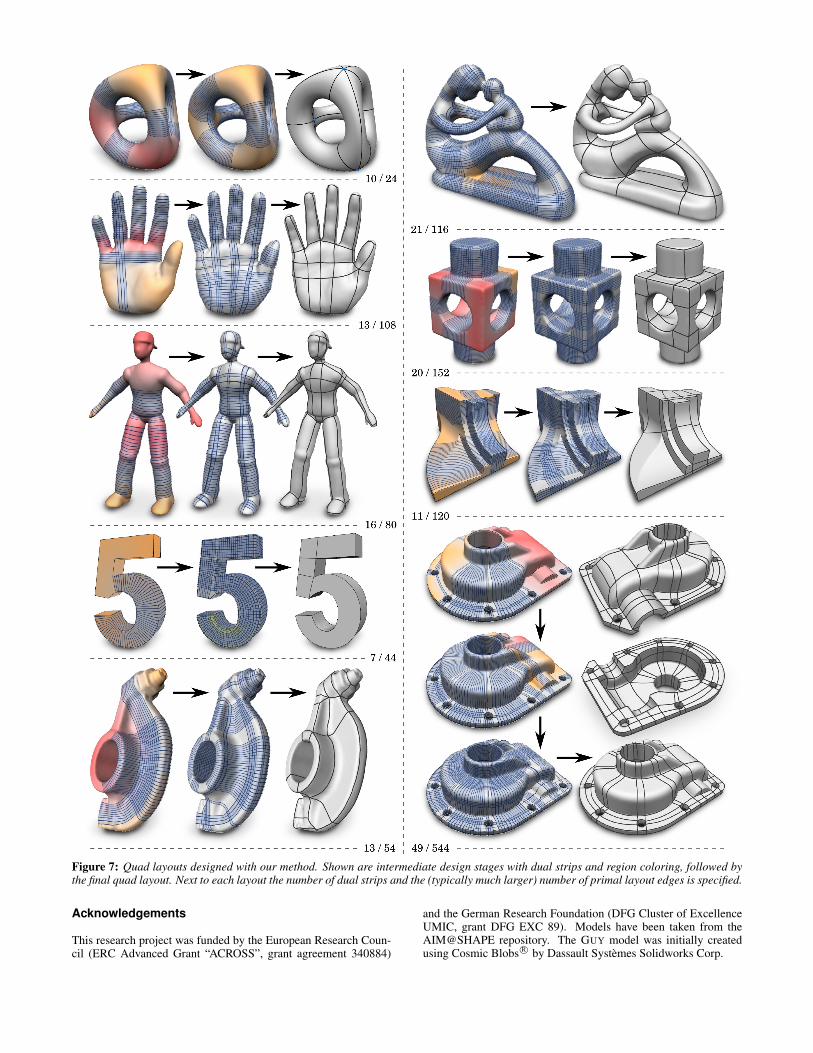
Figure 7: Quad layouts designed with our method. Shown are intermediate design stages with dual strips and region coloring, followed bythe final quad layout. Next to each layout the number of dual strips and the (typically much larger) number of primal layout edges is specified.
Acknowledgements
This research project was funded by the European Research Coun-cil (ERC Advanced Grant “ACROSS”, grant agreement 340884)
and the German Research Foundation (DFG Cluster of ExcellenceUMIC, grant DFG EXC 89). Models have been taken from theAIM@SHAPE repository. The GUY model was initially createdusing Cosmic Blobs R© by Dassault Systemes Solidworks Corp.
References
BEINEKE, L. W. 1968. Derived graphs of digraphs. In Beitragezur Graphentheorie. Teubner, Leipzig, 17–33.
BISCHOFF, S., WEYAND, T., AND KOBBELT, L. 2005. Snakes ontriangle meshes. In Bildverarbeitung fur die Medizin, 208–212.
BOIER-MARTIN, I. M., RUSHMEIER, H. E., AND JIN, J. 2004.Parameterization of triangle meshes over quadrilateral domains.In Proc. SGP ’04, 197–208.
BOMMES, D., VOSSEMER, T., AND KOBBELT, L. 2008. Quad-rangular parameterization for reverse engineering. MathematicalMethods for Curves and Surfaces, 55–69.
BOMMES, D., ZIMMER, H., AND KOBBELT, L. 2009. Mixed-integer quadrangulation. In Proc. SIGGRAPH 2009, 1–10.
BOMMES, D., LEMPFER, T., AND KOBBELT, L. 2011. Globalstructure optimization of quadrilateral meshes. ComputerGraphics Forum 30, 2, 375–384.
BOMMES, D., LEVY, B., PIETRONI, N., PUPPO, E., SILVA, C.,TARINI, M., AND ZORIN, D. 2013. Quad-mesh generation andprocessing: A survey. Computer Graphics Forum 32, 6, 51–76.
BOMMES, D., CAMPEN, M., EBKE, H.-C., ALLIEZ, P., AND
KOBBELT, L. 2013. Integer-grid maps for reliable quad mesh-ing. In Proc. SIGGRAPH 2013, 98:1–98:12.
BRUCKSTEIN, A., NETRAVALI, A., AND RICHARDSON, T. 2001.Epi-convergence of discrete elastica. Appl.Analysis 79, 137–171.
CAMPEN, M., AND KOBBELT, L. 2014. Quad layout embeddingvia aligned parameterization. Computer Graphics Forum.
CAMPEN, M., BOMMES, D., AND KOBBELT, L. 2012. Dualloops meshing: quality quad layouts on manifolds. In Proc. SIG-GRAPH 2012, 110:1–110:11.
COHEN-STEINER, D., AND MORVAN, J.-M. 2003. Restricteddelaunay triangulations and normal cycle. In Proc. Symp. Comp.Geom., SCG ’03, 312–321.
DANIELS, J., SILVA, C. T., AND COHEN, E. 2009. Semi-regular quadrilateral-only remeshing from simplified base do-mains. Comput. Graph. Forum 28, 5, 1427–1435.
DIAMANTI, O., VAXMAN, A., PANOZZO, D., AND SORKINE-HORNUNG, O. Designing N -PolyVector fields with complexpolynomials. Computer Graphics Forum 33, 5, 1–11.
DONG, S., BREMER, P.-T., GARLAND, M., PASCUCCI, V., AND
HART, J. C. 2006. Spectral surface quadrangulation. In Proc.SIGGRAPH 2006, 1057–1066.
EBKE, H.-C., CAMPEN, M., BOMMES, D., AND KOBBELT, L.2014. Level-of-detail quad meshing. In Proc. SIGGRAPH Asia2014.
ECK, M., AND HOPPE, H. 1996. Automatic reconstruction ofB-spline surfaces of arbitrary topological type. In Proc. SIG-GRAPH 96, 325–334.
HOFER, M., AND POTTMANN, H. 2004. Energy-minimizingsplines in manifolds. ACM Trans. Graph. 23, 3, 284–293.
JI, Z., LIU, L., AND WANG, Y. 2010. B-mesh: A modelingsystem for base meshes of 3d articulated shapes. In Proc. PacificGraphics ’10, 2169–2178.
KALBERER, F., NIESER, M., AND POLTHIER, K. 2007. Quad-cover - surface parameterization using branched coverings. Com-puter Graphics Forum 26, 3, 375–384.
KNOPPEL, F., CRANE, K., PINKALL, U., AND SCHRODER, P.2013. Globally optimal direction fields. ACM Trans. Gra. 32, 4.
KOVACS, D., MYLES, A., AND ZORIN, D. 2011. Anisotropicquadrangulation. Comp. Aided Geom. Design 28, 8, 449–462.
KRISHNAMURTHY, V., AND LEVOY, M. 1996. Fitting smoothsurfaces to dense polygon meshes. In Proc. SIGGRAPH 96, 313–324.
LAI, Y.-K., JIN, M., XIE, X., HE, Y., PALACIOS, J., ZHANG, E.,HU, S.-M., AND GU, X. 2010. Metric-driven rosy field designand remeshing. IEEE Trans. Vis. Comput. Graph. 16, 1, 95–108.
LEE, Y., AND LEE, S. 2002. Geometric snakes for triangularmeshes. Comput. Graph. Forum 21, 3, 229–238.
LEE, A. W. F., SWELDENS, W., SCHRODER, P., COWSAR, L.,AND DOBKIN, D. 1998. MAPS: Multiresolution adaptive pa-rameterization of surfaces. In Proc. SIGGRAPH ’98, 95–104.
LI, W.-C., RAY, N., AND LEVY, B. 2006. Automatic and interac-tive mesh to t-spline conversion. In Proc. SGP ’06, 191–200.
MITRA, N. J., PAULY, M., WAND, M., AND CEYLAN, D. 2013.Symmetry in 3d geometry: Extraction and applications. Comput.Graph. Forum 32, 6, 1–23.
MURDOCH, P., BENZLEY, S., BLACKER, T., AND MITCHELL,S. A. 1997. The spatial twist continuum: a connectivity basedmethod for representing all-hexahedral finite element meshes.Finite Elem. Anal. Des. 28, 137–149.
MYLES, A., PIETRONI, N., KOVACS, D., AND ZORIN, D. 2010.Feature-aligned T-meshes. In Proc. SIGGRAPH 2010, 117:1–117:11.
PALACIOS, J., AND ZHANG, E. 2007. Rotational symmetry fielddesign on surfaces. In Proc. SIGGRAPH 2007, 55:1–55:10.
PANOZZO, D., LIPMAN, Y., PUPPO, E., AND ZORIN, D. 2012.Fields on symmetric surfaces. In Proc. SIGGRAPH 2012, 111.
PANOZZO, D., BARAN, I., DIAMANTI, O., AND SORKINE-HORNUNG, O. 2013. Weighted averages on surfaces. ACMTrans. Graph. 32, 4, 60:1–60:12.
RAY, N., VALLET, B., ALONSO, L., AND LEVY, B. 2009.Geometry-aware direction field processing. ACM Trans. Graph.29, 1, 1:1–1:11.
SCHMIDT, R. 2013. Stroke parameterization. Comp. Graph. Forum32, 2, 255–263.
SCHOENEMANN, T., AND CREMERS, D. 2007. Introducing curva-ture into globally optimal image segmentation: Minimum ratiocycles on product graphs. In Proc. ICCV 2007, 1–6.
SCHOENEMANN, T., MASNOU, S., AND CREMERS, D. 2011.The elastic ratio: Introducing curvature into ratio-based imagesegmentation. IEEE Trans. Img. Proc. 20, 9, 2565–2581.
TAKAYAMA, K., PANOZZO, D., SORKINE-HORNUNG, A., AND
SORKINE-HORNUNG, O. 2013. Sketch-based generation andediting of quad meshes. In Proc. SIGGRAPH 2013, 97:1–97:8.
TARINI, M., PUPPO, E., PANOZZO, D., PIETRONI, N., AND
CIGNONI, P. 2011. Simple quad domains for field aligned meshparametrization. Proc. SIGGRAPH Asia 2011, 142:1–142:12.
TONG, Y., ALLIEZ, P., COHEN-STEINER, D., AND DESBRUN,M. 2006. Designing quadrangulations with discrete harmonicforms. In Proc. SGP ’06, 201–210.
ZHANG, M., HUANG, J., LIU, X., AND BAO, H. 2010. A wave-based anisotropic quadrangulation method. In Proc. SIGGRAPH2010, 118:1–118:8.