Embed Size (px)
Citation preview
Submittal Package
DUAL-VORTEX SEPARATOR
1 - Features & BeneFits
2 - Product sPeciFications
3 - insPections & Maintenance
table of contentS

Features & BeneFits
Section 1
Call us today (800) 579-8819 or visit our website for detailed product information, drawings and
design tools at www.oldcastlestormwater.com
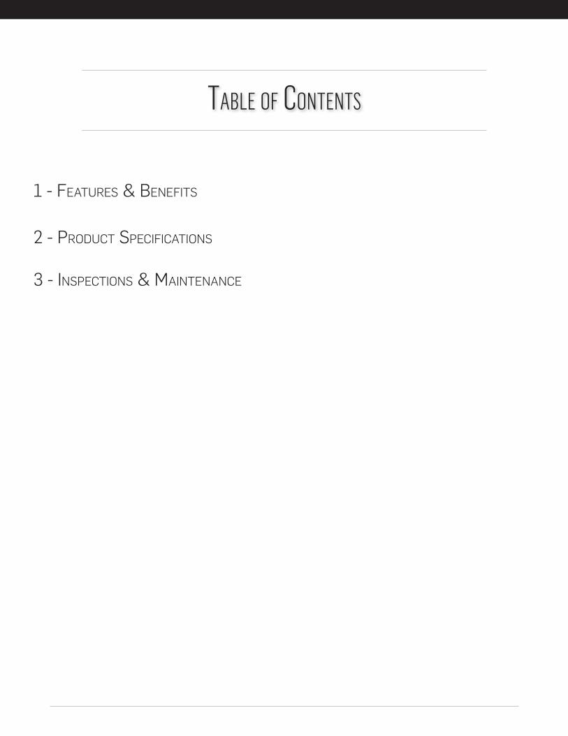
DUAL-VORTEX SEPARATOREnhanced Gravity Separation of Stormwater Pollutants in a Compact Configuration
HYDRODYNAMIC SEPARATION
Dual-Vortex EfficiencyParticle settling is enhanced by circular
flow patterns and a highly circuitous flow path created by two independent vortex cylinders.
Settled particles are collected in the isolated bottom storage area, while floating trash, debris and petroleum hydrocarbons are retained in the cylinders and upper storage areas.
During peak events, flows in excess of design treatment overtop the bypass weir and exit the system without entering the cylinders and lower storage area, thereby eliminating re-entrainment issues.
FEATURES BENEFITS
Economical Installation
Access Options
Online System Capability
Durable Construction
Proven Performance
Treatment Train
Maintenance Accessible Design
Can be installed upstream of infiltration, detention and retention systems or other treatment BMP’s
Third party tested and certified
Stainless-steel components installed in a reinforced concrete structure
Internal high-flow bypass weir system provides for online or offline configurations
Multiple access options (manhole cover or optional hinged lid) allow for site-specific customization
Prepackaged and provided as compact round or square manholes or small vaults
Open access to accumulated floatables and two access points to sediment storage area
(800) 579-8819
oldcastlestormwater.com © 2017 Oldcastle Precast, Inc.
OSS_DVS Insert_032017_v5
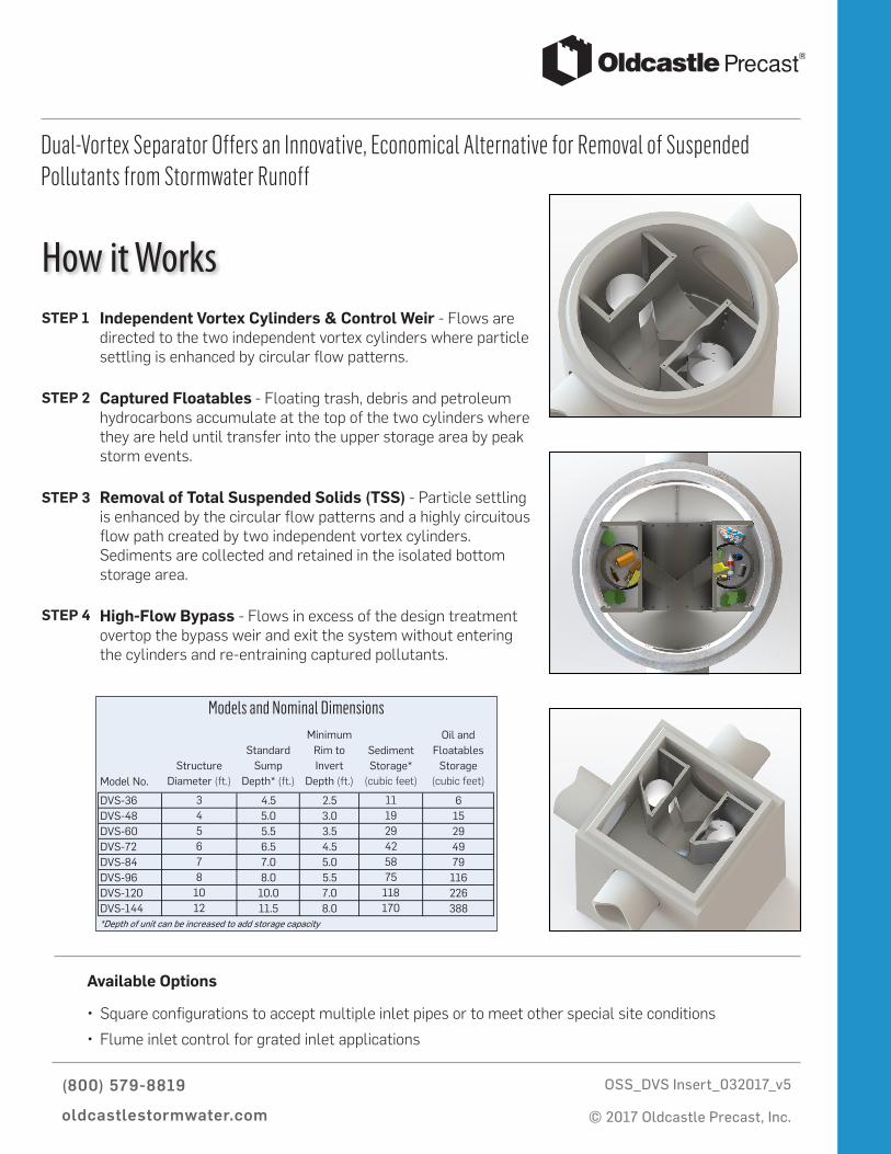
Dual-Vortex Separator Offers an Innovative, Economical Alternative for Removal of Suspended Pollutants from Stormwater Runoff
STEP 1 Independent Vortex Cylinders & Control Weir - Flows are directed to the two independent vortex cylinders where particle settling is enhanced by circular flow patterns.
Captured Floatables - Floating trash, debris and petroleum hydrocarbons accumulate at the top of the two cylinders where they are held until transfer into the upper storage area by peak storm events.
Removal of Total Suspended Solids (TSS) - Particle settling is enhanced by the circular flow patterns and a highly circuitous flow path created by two independent vortex cylinders. Sediments are collected and retained in the isolated bottom storage area.
High-Flow Bypass - Flows in excess of the design treatment overtop the bypass weir and exit the system without entering the cylinders and re-entraining captured pollutants.
STEP 2
STEP 3
STEP 4
Model No.Structure
Diameter (ft.)
Standard Sump
Depth* (ft.)
Minimum Rim to Invert
Depth (ft.)
Sediment Storage*
(cubic feet)
Oil and Floatables
Storage (cubic feet)
DVS-36 3 4.5 2.5 11 6DVS-48 4 5.0 3.0 19 15DVS-60 5 5.5 3.5 29 29DVS-72 6 6.5 4.5 42 49DVS-84 7 7.0 5.0 58 79DVS-96 8 8.0 5.5 75 116DVS-120 10 10.0 7.0 118 226DVS-144 12 11.5 8.0 170 388*Depth of unit can be increased to add storage capacity
Models and Nominal Dimensions
Available Options
• Square configurations to accept multiple inlet pipes or to meet other special site conditions
• Flume inlet control for grated inlet applications
Product sPeciFications
Section 2
Section 02722
STORMWATER TREATMENT SYSTEM
Table of Contents
PART 1 — GENERAL
1.1 Related Requirements1.2 Summary1.3 Reference Standards1.4 Definitions1.5 Submittals1.6 Delivery, Storage, and Handling
PART 2 — PRODUCTS
2.1 Hydrodynamic Separator2.1.1 Description 2.1.2 Materials and Design2.1.3 Performance2.1.4 Quality Assurance2.1.5 Manufacturer
PART 3 — Execution
3.1 Earthwork3.2 Identification3.3 Inspection
3.3.1 General3.3.2 Manhole Sections
3.4 Structure Installation3.4.1 General3.4.2 Trench Excavation
3.4.2.1 Excavation3.4.2.2 Dewatering3.4.2.3 Removal of Rock3.4.2.4 Removal of Unstable Material
3.4.3 Bedding3.4.4 Setting Structures3.4.5 Jointing3.4.6 Backfilling
3.4.6.1 General 3.4.6.2 Backfilling Manhole Sections in Trenches3.4.6.3 Movement of Construction Machinery
PART 1 — GENERAL 1.1
Related Requirements
A. Section 01330 – Submittals: Shop Drawings, Product Data, and Samples
B. Section 02300 – Earthwork: Excavation, Trenching, Backfill, and Compaction.
C. Section 02370 – Erosion and Sedimentation Control (Including SWPPP)
1.2 Summary
A. This section includes hydrodynamic structural stormwater treatment devices.
1.3 Reference Standards
A. American Association of State Highway and Transportation Officials (AASHTO)
a. AASHTO M105 – Gray Iron Castings
B. American Society for Testing and Materials (ASTM)
a. ASTM A48, CL.30B – Gray Iron Castings
b. ASTM A82 – Steel Wire, Plain, for Concrete Reinforcement
c. ASTM A185 – Steel Welded Wire Reinforcement, Plain for Concrete
d. ASTM A496 – Steel Wire, Deformed, for Concrete Reinforcement
e. ASTM A497 – Steel Welded Wire Reinforcement, Deformed for Concrete
f. ASTM A615 – Deformed and Plain, Carbon-Steel Bars for Concrete Reinforcement
g. ASTM B209 – Aluminum, Aluminum Alloy Sheet and Plate
h. ASTM C32 – Sewer and Manhole Brick (Made form Clay or Shale)
i. ASTM C139 – Concrete Masonry Units for Construction of Catch Basins and Manholes
j. ASTM C150 – Portland Cement
k. ASTM C478 – Precast Reinforced Concrete Manhole Sections
l. ASTM C595 – Blended Hydraulic Cement
m. ASTM C857 – Minimum Structural Design Loading for Underground Precast ConcreteUtility Structures

n. ASTM C858 – Underground Precast Concrete Utility Structures
o. ASTM C891 – Installation of Underground Precast Utility Structures
p. ASTM C990 – Joints for Concrete Pipe, Manholes, and Precast BoxSections Using Preformed Flexible Joint Sealants
q. ASTM C1107 – Packaged Dry, Hydraulic Cement Grout (Non-Shrink)
r. ASTM D698 – Test Methods for Laboratory Compaction Characteristicsof Soil Using Standard Effort
1.4 Definitions
A. BMP: Best Management Practices
B. TSS: Total Suspended Solids
1.5 Submittals
The following shall be submitted by contractor in accordance with Section 01330 Submittal Procedures:
A. Product Data for the following:
a. Hydrodynamic Separator
1. Product specifications to include but not limited to specificationsheets, brochures, and performance claims.
2. Installation procedures
3. Shop drawings shall be provided to include details for fabrication,construction, reinforcement, joints, assembly, and any accessoryitems. Shop drawings shall be annotated to indicate all materials tobe used and applicable material standards, required tests ofmaterials, and all design assumptions for structural analysis.
B. Independent third party certification or test report demonstrating conformance toapplicable local or regional BMP standards before the treatment system is installedfor the following:
1. Removal efficiency
2. Targeted pollutants of concern
3. Hydraulic capacity
4. Certification of adherence to applicable standard
C. Products submitted as approved equal must be submitted at least two weeks prior toproject bid opening and must be approved by project engineer. Submittal forapproved equal product must contain a signed letter from an executive officer of themanufacturer stating product is equivalent to all applicable requirements of thisspecification and shall include all items listed in section 1.6B of this specification.

1.6 Delivery, Storage, and Handling
A. All treatment system components shall be delivered to the site and unloadedwith handling that conforms to the manufacturer’s instructions for reasonable care.Concrete and internal components shall not be rolled or dragged over gravel or rockduring handling. The Contractor shall take necessary precautions to ensure themethod used in lifting or placing the treatment system does not induce stressfatigue in the concrete.
PART 2 — PRODUCTS 2.1
Hydrodynamic Separator
2.1.1 Description
The Contractor, and/or a manufacturer selected by the Contractor and approved by the Engineer, shall furnish all labor, materials, equipment and incidentals required and install all precast concrete stormwater treatment systems and appurtenances in accordance with the Drawings and these Specifications. The treatment system shall provide flow partitioned hydrodynamic treatment that removes sediment, free-floating pollutants, and oil particles. The treatment system must include the capability to partition flows, causing all runoff to be diverted into the treatment chamber during low-flow conditions. Flows exceeding the treatment capacity of the unit shall divert the excess flow around the treatment chamber to prevent re-suspension and washout of previously trapped pollutants.
2.1.2 Materials and Design
A. Concrete for precast stormwater treatment systems shall conform to ASTM C857and C858 and meet the following additional requirements:
1. In all cases the wall thickness shall be no less than the minimum thicknessnecessary to sustain HS20-44 (MS18) loading requirements as determinedby a Licensed Professional Engineer.
2. Sections shall have tongue and groove or ship-lap joints with a butyl masticsealant conforming to ASTM C 990.
3. Cement shall be Type I, II, or III Portland cement conforming to ASTM C 150.
4. All sections shall be cured by an approved method. Sections shall not beshipped until the concrete has attained a compressive strength of 4,000 psi(28 MPa) or other designate suitable handling strength.
5. Pipe openings shall be sized to accept pipes of the specified size(s) andmaterial(s), and shall be sealed by the Contractor with hydraulic cementconforming to ASTM C 595M or ASTM C1107.
6. Aggregates shall conform to ASTM C33, except that therequirement for gradation shall not apply.
7. Reinforcement shall consist of wire conforming to ASTM A82 orA496, of wire mesh conforming to ASTM A185 or A497, or Grade 40steel bars conforming to ASTM A615.
8. Castings for manhole frames and covers shall be in accordance withASTM A48, CL.30B and AASHTO M105. The access cover/s shall bedesigned for HS20-44 traffic loading and shall provide a minimum of30-inch clear opening.
9. Brick or masonry used to build the manhole frame to grade shallconform to ASTM C32 or ASTM C139 and shall be installed inconformance with all local requirements.
10. Diversion weirs, separation chamber, and oil baffle shall be madefrom marine grade fiberglass and/or stainless steel and shallconform to ASTM A240.
11. All mounting hardware for internal components shall be made of304SS and shall conform to ASTM A240.
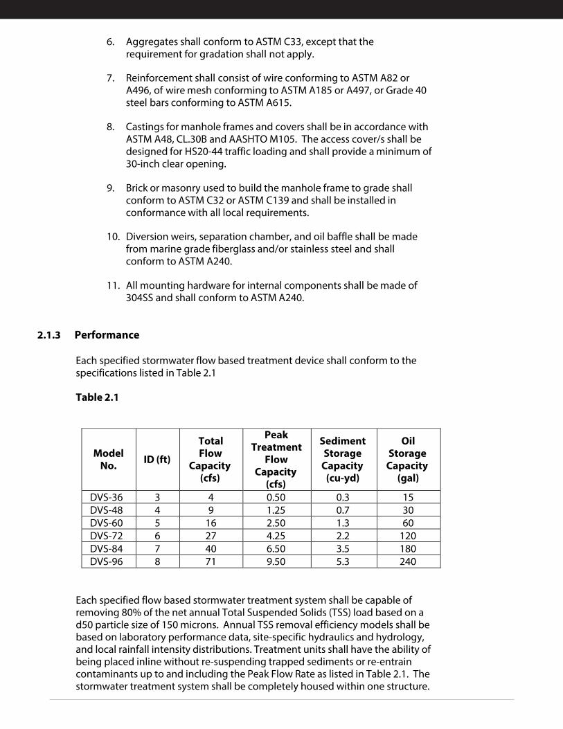
2.1.3 Performance
Each specified stormwater flow based treatment device shall conform to the specifications listed in Table 2.1
Table 2.1
Model No. ID (ft)
Total Flow
Capacity (cfs)
Peak Treatment
Flow Capacity
(cfs)
Sediment Storage
Capacity (cu-yd)
Oil Storage
Capacity (gal)
DVS-36 3 4 0.50 0.3 15 DVS-48 4 9 1.25 0.7 30 DVS-60 5 16 2.50 1.3 60 DVS-72 6 27 4.25 2.2 120 DVS-84 7 40 6.50 3.5 180 DVS-96 8 71 9.50 5.3 240
Each specified flow based stormwater treatment system shall be capable of removing 80% of the net annual Total Suspended Solids (TSS) load based on a d50 particle size of 150 microns. Annual TSS removal efficiency models shall be based on laboratory performance data, site-specific hydraulics and hydrology, and local rainfall intensity distributions. Treatment units shall have the ability of being placed inline without re-suspending trapped sediments or re-entrain contaminants up to and including the Peak Flow Rate as listed in Table 2.1. The stormwater treatment system shall be completely housed within one structure.
2.1.4 Quality Assurance
The materials, process and finished stormwater treatment system shall be subject to inspection by the Engineer. Acceptance or rejection of the system shall be based on the Specifications contained in this section. Imperfections may be repaired but subject to the acceptance of the Engineer.
2.1.5 Manufacturer
Each stormwater treatment system shall be a Dual-Vortex Separator (DVS) as manufactured by Oldcastle Precast, 7100 Longe Street, Stockton, California, 95206.
PART 3 — Execution
3.1 Earthwork
A. Excavation, trenching, and backfilling shall be as specified in Division 2 Section“Earthwork.”
3.2 Identification
A. All stormwater treatment devices shall be identified at the surface level withmarkings indicating that they are treatment devices.
3.3 Inspection
3.3.1 General
A. Concrete, internals, and accessories, shall be inspected prior to installation andany defective or damaged product shall be replaced.
3.3.2 Manhole Sections
A. Any manhole section with chipped bells or spigots shall be rejected and replaced.
B. Any section with a fracture or crack greater than 0.10 in. in length or 0.01 in width shallbe rejected and replaced.
C. Any manhole section has not had at least 7 days cure time (including 12 hours steamcure, or 21 days without steam cure) or is out of round shall be rejected and replaced.
D. Any section with indications of imperfections in mixing and/or molding, honeycombed,or open textured surface, shall be rejected and replaced.
E. Any section with indications of patches or repairs shall be rejected and replaced.
F. Any section with exposed reinforcing steel shall be rejected and replaced.
3.4 Structure Installation
3.4.1 General
A. General Locations and Arrangements: Drawing plans and details indicate generallocation and arrangement of underground storm and drainage piping systems.Location and arrangement of stormwater treatment systems is critical and designconsideration should be taken into account. Install treatment system as indicatedherein and as directed by the product manufacturer, to the maximum extentpractical. Where specific installation procedure is not indicated, follow productmanufacturer’s written instructions.
B. All products shall be inspected for defects and cracks before being lowered into thetrench, piece by piece. Any defective, damaged or unsound structure or anyproduct that has had its grade disturbed after laying, shall be taken up and replaced.Open ends shall be protected with a pipe plug to prevent earth or other materialfrom entering the treatment system during construction. The interior of thetreatment system shall be free from dirt, excess water and other foreign materials asthe installation progresses and left clean at the completion of the installation.
3.4.2 Trench Excavation
3.4.2.1 Excavation
A. Excavate trenches to ensure that sides will be stable under all workingconditions. Slope trench walls or provide supports in conformance with alllocal and national standards for safety. Open only as much trench as can besafely maintained by available equipment. Backfill all trenches as soon aspracticable, but not later than the end of each working day.
B. Where trench walls are stable or supported, provide a width sufficient, but nogreater than necessary, to ensure working room to properly and safely placeand compact haunching and other embedment materials. The spacebetween the treatment system and trench wall must be wider than thecompaction equipment used in the compaction zone.
C. When supports such as trench sheeting, trench jacks, trench shields or boxesare used, ensure that support of the treatment system and its embedment ismaintained throughout installation. Ensure that sheeting is sufficiently tightto prevent washing out of the trench wall from behind the sheeting. Providetight support of trench walls below viaducts, existing utilities, or otherobstructions that restrict driving of sheeting.
3.4.2.2 Dewatering
A. Do not lay or embed any section of the stormwater treatment system instanding or running water. At all times prevent runoff and surface waterfrom entering the trench.
B. When water is present in the work area, dewater to maintain stability ofin-situ and imported materials. Maintain water level below pipe bedding andfoundation to provide a stable trench bottom. Use, as appropriate, sumppumps, well points, deep wells, geofabrics, perforated underdrains, or stoneblankets of sufficient thickness to remove and control water in the trench.When excavating while depressing ground water, ensure the ground water isbelow the bottom of cut at all times to prevent washout from behindsheeting or sloughing of exposed trench walls. Maintain control of water inthe trench before, during, and after pipe system installation and untilembedment is installed and sufficient backfill has been placed to preventflotation of the pipe, fitting, or drainage structures. To preclude loss of soilsupport, employ dewatering methods that minimize removal of fines and thecreation of voids in in-situ materials.
3.4.2.3 Removal of Rock
A. Rock in either ledge or boulder formation shall be replaced with suitablematerials to provide a compacted earth cushion having a thickness betweenexposed rock and the manhole sections of at least 12 inches (0.3m). Rockexcavation shall be as specified and defined under section 02300 "Earthwork".
3.4.2.4 Removal of Unstable Material
A. Where wet or otherwise unstable soil incapable of properly supportingthe manhole structure, as determined by the Engineer, is encountered in thebottom of a trench, such material shall be removed to at least 24 inchesbelow bottom of the structure and replaced to the proper grade with selectgranular material, compacted as directed by the engineer. When removal ofunstable material is due to the fault or neglect of the Contractor whileperforming shoring and sheeting, water removal, or other specifiedrequirements, such removal and replacement shall be performed at noadditional cost to the Owner.
3.4.3 Bedding
A. A stable and uniform bedding shall be provided for the manhole structure andany protruding features of its joint and/or fittings. The bedding shall be compactedto a minimum of 90% of maximum density per AASHTO T99, or as shown in theplans. Structure bedding shall be a minimum of 6” in thickness. The beddingsurface for the structure shall provide a firm foundation of uniform densitythroughout the entire length of the pipe.
3.4.4 Setting Structures
A. Each structure section shall be thoroughly examined before being placed;defective or damaged sections shall not be used. Structures shall be placed to theelevations as indicated on the plans. Proper facilities shall be provided for loweringstructure sections into trenches. Sections shall not be laid in water, and the sectionsshall not be laid when trench conditions or weather are unsuitable for such work.Diversion of drainage or dewatering of trenches shall be provided as directed by theengineer; see dewatering section.
3.4.5 Jointing
A. Joints shall be constructed as described herein and in accordance withmanufacturer’s installation instructions.
B. All bell-and-spigot manhole joints shall be thoroughly cleaned. The suppliedgasket shall be installed on the spigot end with the angled surface facing towardthe mating surface. Joint lubricant, supplied by the manufacturer, shall be liberallyapplied to entire interior of bell and gasket on spigot prior to assembly. Sectionsshall be mated with sections level and plumb to prevent rolling the gasket.
C. All tongue-and-groove joints shall be thoroughly cleaned. Sections shall be matedand hydraulic cement grout (non-shrink) complying with ASTM C1107 shall beapplied liberally to the exterior and exterior of the joint ensuring all voids are filledcompletely.
3.4.6 Backfilling
3.4.6.1 General
Backfill placement and compaction shall be constructed in accordance with the specifications herein and the product manufacturer’s published installation guides.
3.4.6.2 Backfilling Manhole Sections in Trenches
After the manhole sections and connecting pipes have been properly bedded, selected material from excavation or borrow, at a moisture content that will facilitate compaction, shall be placed along all sides of pipe in layer depths to ensure minimum compaction density is obtained evenly throughout the backfill material. The backfill shall be brought up evenly on all sides of the structure. Each layer shall be thoroughly compacted with mechanical tampers or rammers. Tests for density shall be made as necessary to ensure conformance to the compaction requirements specified below. Where it is necessary, in the opinion of the Engineer, that sheeting or portions of bracing used be left in place, the contract will be adjusted accordingly. Untreated sheeting shall not be left in place beneath structures or pavements.
3.4.6.3 Movement of Construction Machinery
Movement of construction machinery over a manhole structure at any stage of construction shall be at the Contractor's risk. Any damaged structure shall be repaired or replaced.
insPections & Maintenance
Section 3
DescriptionThe Dual-Vortex Separator (DVS) is a hydrodynamic stormwater treatment device used to remove pollutants from urban runoff. Impervious surfaces and other urban and suburban landscapes generate a variety of contaminants that can enter stormwater and pollute downstream receiving waters. The DVS is designed to capture and retain sediment as well as floating trash, debris and oils. The concentration of metals and other constituents associated with sediment or floating pollutants may also be reduced.
FunctionStormwater runoff enters the DVS unit through an inlet pipe. Influent flow is split evenly between two vortex tubes by a V-shaped weir. The shape and diameter of the vortex tubes promotes circular motion of the incoming stormwater at increased velocities to enhance particle settling through centrifugal force. The system is also designed with an extended flow path to maximize hydraulic residence time which allows increased time to settle out solids. Settled pollutants are collected in an isolated storage area at the bottom of the structure, while floating trash, debris and petroleum hydrocarbons are retained behind baffles that contain the vortex chambers. During peak runoff events, flow in excess of design treatment flow overtops the bypass weir and exits the system without entering the treatment chambers to interrupt the treatment process or re-entrain captured pollutants. Treatment and bypass flows exit the system through an outlet pipe that is plumbed at the same elevation as the inlet pipe.
ConfigurationThe internal components of the DVS system are fabricated from stainless steel and mounted in a manhole or vault structure. The system is typically delivered as a complete unit for installation by the contractor. Installation includes excavation, preparation of the base rock, setting the unit, plumbing the inlet and outlet piping, backfill and placement of the finished surface at grade. Access to the installed system is allowed through ductile iron casting or hatch covers. The number of access points provided is dependent on the size and configuration of the system.
Maintenance OverviewState and local regulations require all stormwater management systems to be inspected on a regular basis and maintained as necessary to ensure performance and protect downstream receiving waters. Without maintenance, excessive pollutant buildup can limit system performance by reducing the operating capacity and increase the potential for scouring of pollutants during periods of high flow.
Inspection EquipmentThe following equipment is helpful when conducting DVS inspections:
• Recording device (pen and paper form, voice recorder, iPad, etc.)• Suitable clothing (appropriate footwear, gloves, hardhat, safety glasses, etc.)• Traffic control equipment (cones, barricades, signage, flagging, etc.)• Manhole hook or pry bar• Flashlight• Tape measure• Measuring stick or sludge sampler• Long-handled net (optional)• Replacement sorbent pads
Inspection ProceduresInspection is essential to consistent system performance and is easily completed. Inspection is typically conducted a minimum of twice per year but since pollutant transport and deposition varies from site to site, a site-specific maintenance frequency should be established during the first two or three years of operation.
DVS inspections are visual and are conducted without entering the unit. To complete an inspection, safety measures including traffic control should be deployed before the access covers are removed. Once the covers have been removed, the following items should be checked and recorded (see form provided on page 5) to determine whether maintenance is required:
• Inspect the internal components and note whether there are any broken or missing parts. In theunlikely event that internal parts are broken or missing, contact Oldcastle Stormwater at(800) 579-8819 to determine appropriate corrective action.
• Note whether the inlet or outlet pipe is blocked or obstructed.
• Observe, quantify and record the accumulation of floating trash and debris in the baffled chambersaround the vortex tubes. The significance of accumulated floating trash and debris is a matter ofjudgement. A long-handled net may be used to retrieve the bulk of trash and debris at the time ofinspection if full maintenance due to accumulation of oils or sediment is not yet warranted.
• Observe, quantify and record the accumulation of oils in the baffled chambers around the vortextubes. If sorbent pads have been used to absorb free oil and grease, observe and record theircondition. Unless the sorbent pads are tethered to the internal baffles, spent pads may be nettedand replaced at the time of inspection. The significance of accumulated floating oils is a matter ofjudgement. However, if there is evidence of an oil or fuel spill, immediate maintenance iswarranted.
• Finally, observe, quantify and record the accumulation of sediment in the sediment storage sump.A calibrated dipstick, tape measure or sludge sampler may be used to determine the amount ofaccumulated sediment. The depth of sediment may be determined by calculating the differencebetween the measurement from the rim of the DVS to the top of the accumulated sediment and themeasurement from the rim of the DVS to the bottom of the DVS structure. Finding the top of theaccumulated sediment takes some practice and a light touch, but increasing resistance as themeasuring device is lowered toward the bottom of the unit indicates the top of theaccumulated sediment.
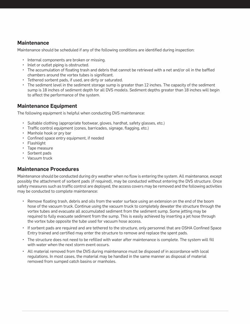
MaintenanceMaintenance should be scheduled if any of the following conditions are identified during inspection:
• Internal components are broken or missing.• Inlet or outlet piping is obstructed.• The accumulation of floating trash and debris that cannot be retrieved with a net and/or oil in the baffled
chambers around the vortex tubes is significant.• Tethered sorbent pads, if used, are dirty or saturated.• The sediment level in the sediment storage sump is greater than 12 inches. The capacity of the sediment
sump is 18 inches of sediment depth for all DVS models. Sediment depths greater than 18 inches will beginto affect the performance of the system.
Maintenance EquipmentThe following equipment is helpful when conducting DVS maintenance:
• Suitable clothing (appropriate footwear, gloves, hardhat, safety glasses, etc.)• Traffic control equipment (cones, barricades, signage, flagging, etc.)• Manhole hook or pry bar• Confined space entry equipment, if needed• Flashlight• Tape measure• Sorbent pads• Vacuum truck
Maintenance ProceduresMaintenance should be conducted during dry weather when no flow is entering the system. All maintenance, except possibly the attachment of sorbent pads (if required), may be conducted without entering the DVS structure. Once safety measures such as traffic control are deployed, the access covers may be removed and the following activities may be conducted to complete maintenance:
• Remove floating trash, debris and oils from the water surface using an extension on the end of the boomhose of the vacuum truck. Continue using the vacuum truck to completely dewater the structure through thevortex tubes and evacuate all accumulated sediment from the sediment sump. Some jetting may berequired to fully evacuate sediment from the sump. This is easily achieved by inserting a jet hose throughthe vortex tube opposite the tube used for vacuum hose access.
• If sorbent pads are required and are tethered to the structure, only personnel that are OSHA Confined SpaceEntry trained and certified may enter the structure to remove and replace the spent pads.
• The structure does not need to be refilled with water after maintenance is complete. The system will fillwith water when the next storm event occurs.
• All material removed from the DVS during maintenance must be disposed of in accordance with localregulations. In most cases, the material may be handled in the same manner as disposal of materialremoved from sumped catch basins or manholes.
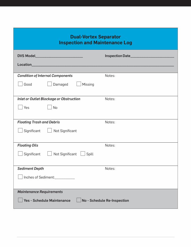
Inlet or Outlet Blockage or Obstruction Notes:
Yes No
Dual-Vortex SeparatorInspection and Maintenance Log
DVS Model__________________________ Inspection Date________________________
Location______________________________________________________________________________
Condition of Internal Components Notes:
Good Damaged Missing
Floating Trash and Debris Notes:
Significant Not Significant
Floating Oils Notes:
Significant Not Significant Spill
Sediment Depth Notes:
Inches of Sediment:___________
Maintenance Requirements
Yes - Schedule Maintenance No - Schedule Re-Inspection
www.oldcastlestormwater.com800-579-8819
BUILDINGSTRUCTURES
OUR MARKETS
TRANSPORTATION
WATER
ENERGYCOMMUNICATIONS
DUAL-VORTEX SEPARATOR


![Double vortex generators for increasing the separation ... › deanshipfiles › pub10583101882.pdfDerkson [17] for a single-phase flow separator with a single tangential inlet and](https://img.pdfslide.net/doc/110x75/60bf1eb98c27a21ba903f1b1/double-vortex-generators-for-increasing-the-separation-a-deanshipfiles-a.jpg)