Embed Size (px)
Citation preview
PSJ; Reviewed: RRR 6/25/14
Solution & Interoperability Test Lab Application Note ©2014 Avaya Inc. – Proprietary and Confidential
1 of 32 CMDupAppNote.doc
Solution & Interoperability Test Lab
Duplicated Avaya AuraTM Communication Manager on VMware
Abstract Avaya Aura Communication Manager (CM) can be deployed in a duplicated mode providing high availability on VMware infrastructure. By leveraging VMware capabilities known as VMware High Availability and Distributed Resource Scheduler, CM can achieve additional options in high availability and resiliency above the traditional server appliance. This document provides the configuration details of Communication Manager as part of a large solution test. It also provides a summary of performance test results leveraging VMware vMotion, High Availability, and Distributed Resource Scheduler.
Acronyms ........................................................................................................................ 3
PSJ; Reviewed: RRR 6/25/14
Solution & Interoperability Test Lab Application Note ©2014 Avaya Inc. – Proprietary and Confidential
2 of 32 CMDupAppNote.doc
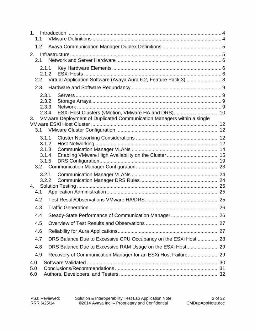
1. Introduction .............................................................................................................. 4
1.1 VMware Definitions ............................................................................................ 4
1.2 Avaya Communication Manager Duplex Definitions .......................................... 5
2. Infrastructure ............................................................................................................ 5 2.1 Network and Server Hardware ........................................................................... 6
2.1.1 Key Hardware Elements .............................................................................. 6 2.1.2 ESXi Hosts .................................................................................................. 6
2.2 Virtual Application Software (Avaya Aura 6.2, Feature Pack 3) ......................... 8
2.3 Hardware and Software Redundancy ................................................................ 9
2.3.1 Servers ........................................................................................................ 9
2.3.2 Storage Arrays ............................................................................................. 9
2.3.3 Network ....................................................................................................... 9
2.3.4 ESXi Host Clusters (vMotion, VMware HA and DRS) ................................ 10 3. VMware Deployment of Duplicated Communication Managers within a single VMware ESXi Host Cluster ........................................................................................... 12
3.1 VMware Cluster Configuration ......................................................................... 12
3.1.1 Cluster Networking Considerations ........................................................... 12 3.1.2 Host Networking ........................................................................................ 12 3.1.3 Communication Manager VLANs .............................................................. 14
3.1.4 Enabling VMware High Availability on the Cluster ..................................... 15 3.1.5 DRS Configuration ..................................................................................... 19
3.2 Communication Manager Configuration ........................................................... 23
3.2.1 Communication Manager VLANs .............................................................. 24
3.2.2 Communication Manager DRS Rules ........................................................ 24
4. Solution Testing ..................................................................................................... 25 4.1 Application Administration ................................................................................ 25
4.2 Test Result/Observations VMware HA/DRS: ................................................... 25
4.3 Traffic Generation ............................................................................................ 26
4.4 Steady-State Performance of Communication Manager .................................. 26
4.5 Overview of Test Results and Observations .................................................... 27
4.6 Reliability for Aura Applications ........................................................................ 27
4.7 DRS Balance Due to Excessive CPU Occupancy on the ESXi Host ............... 28
4.8 DRS Balance Due to Excessive RAM Usage on the ESXi Host....................... 29
4.9 Recovery of Communication Manager for an ESXi Host Failure ...................... 29
4.0 Software Validated .............................................................................................. 30 5.0 Conclusions/Recommendations .......................................................................... 31 6.0 Authors, Developers, and Testers ....................................................................... 32
PSJ; Reviewed: RRR 6/25/14
Solution & Interoperability Test Lab Application Note ©2014 Avaya Inc. – Proprietary and Confidential
3 of 32 CMDupAppNote.doc
Acronyms
AES Application Enablement Services
CCE Call Center Elite
CM Communication Manager
CMS Call Management System
DNIS Dialed Number Information Service
DNS Domain Name Server
DSP Digital Signal Processor
HA High Availability
IOPS Input/Output Operations per Second
LAN Local Area Network
PE Processor Ethernet
PSTN Public Switched Telephone Network
RAID Redundant Array of Independent Disks
SAN Storage Area Network
SAS Serial Attached SCSI
SIL Solution and Interoperability Test Lab
SM Avaya Aura Session Manager
SMGR Avaya Aura System Manager
US Utility Server
WebLM Web Licensing Manager
PSJ; Reviewed: RRR 6/25/14
Solution & Interoperability Test Lab Application Note ©2014 Avaya Inc. – Proprietary and Confidential
4 of 32 CMDupAppNote.doc
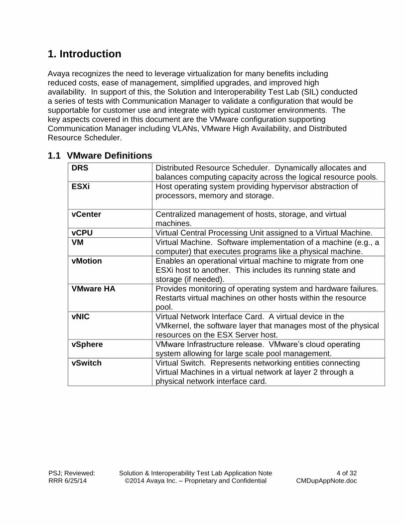
1. Introduction Avaya recognizes the need to leverage virtualization for many benefits including reduced costs, ease of management, simplified upgrades, and improved high availability. In support of this, the Solution and Interoperability Test Lab (SIL) conducted a series of tests with Communication Manager to validate a configuration that would be supportable for customer use and integrate with typical customer environments. The key aspects covered in this document are the VMware configuration supporting Communication Manager including VLANs, VMware High Availability, and Distributed Resource Scheduler.
1.1 VMware Definitions
DRS Distributed Resource Scheduler. Dynamically allocates and balances computing capacity across the logical resource pools.
ESXi Host operating system providing hypervisor abstraction of processors, memory and storage.
vCenter Centralized management of hosts, storage, and virtual machines.
vCPU Virtual Central Processing Unit assigned to a Virtual Machine.
VM Virtual Machine. Software implementation of a machine (e.g., a computer) that executes programs like a physical machine.
vMotion Enables an operational virtual machine to migrate from one ESXi host to another. This includes its running state and storage (if needed).
VMware HA Provides monitoring of operating system and hardware failures. Restarts virtual machines on other hosts within the resource pool.
vNIC Virtual Network Interface Card. A virtual device in the VMkernel, the software layer that manages most of the physical resources on the ESX Server host.
vSphere VMware Infrastructure release. VMware’s cloud operating system allowing for large scale pool management.
vSwitch Virtual Switch. Represents networking entities connecting Virtual Machines in a virtual network at layer 2 through a physical network interface card.
PSJ; Reviewed: RRR 6/25/14
Solution & Interoperability Test Lab Application Note ©2014 Avaya Inc. – Proprietary and Confidential
5 of 32 CMDupAppNote.doc
1.2 Avaya Communication Manager Duplex Definitions
Memory 5GB
vCPUs 3
Hard Disk Virtual disk storage – 30GB.
Network Adapter 1 CM Processor Ethernet
Network Adapter 2 CM Duplication Network. Not routable. Layer 2.
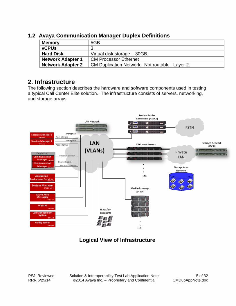
2. Infrastructure The following section describes the hardware and software components used in testing a typical Call Center Elite solution. The infrastructure consists of servers, networking, and storage arrays.
Logical View of Infrastructure
PSJ; Reviewed: RRR 6/25/14
Solution & Interoperability Test Lab Application Note ©2014 Avaya Inc. – Proprietary and Confidential
6 of 32 CMDupAppNote.doc
2.1 Network and Server Hardware
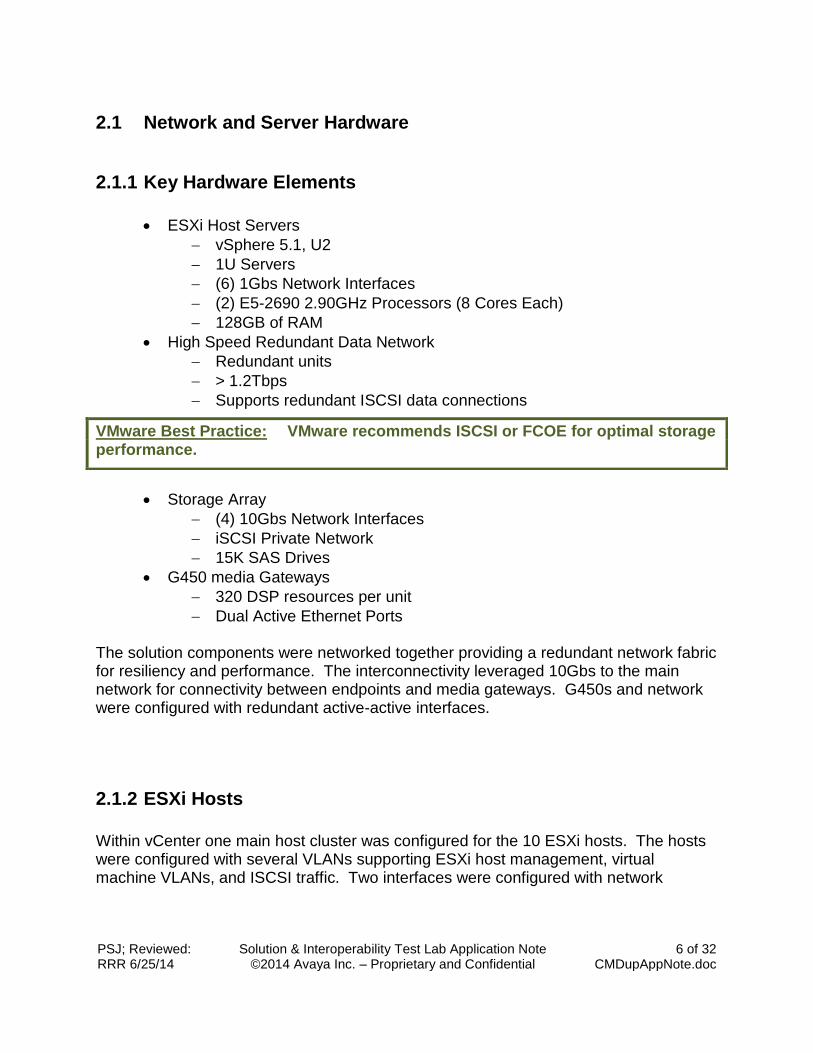
2.1.1 Key Hardware Elements
ESXi Host Servers
vSphere 5.1, U2
1U Servers
(6) 1Gbs Network Interfaces
(2) E5-2690 2.90GHz Processors (8 Cores Each)
128GB of RAM
High Speed Redundant Data Network
Redundant units
> 1.2Tbps
Supports redundant ISCSI data connections
Storage Array
(4) 10Gbs Network Interfaces
iSCSI Private Network
15K SAS Drives
G450 media Gateways
320 DSP resources per unit
Dual Active Ethernet Ports The solution components were networked together providing a redundant network fabric for resiliency and performance. The interconnectivity leveraged 10Gbs to the main network for connectivity between endpoints and media gateways. G450s and network were configured with redundant active-active interfaces.
2.1.2 ESXi Hosts
Within vCenter one main host cluster was configured for the 10 ESXi hosts. The hosts were configured with several VLANs supporting ESXi host management, virtual machine VLANs, and ISCSI traffic. Two interfaces were configured with network
VMware Best Practice: VMware recommends ISCSI or FCOE for optimal storage performance.
PSJ; Reviewed: RRR 6/25/14
Solution & Interoperability Test Lab Application Note ©2014 Avaya Inc. – Proprietary and Confidential
7 of 32 CMDupAppNote.doc
teaming supporting a private network for ISCSI. Two separate interfaces were configured with network teaming for virtual machine VLANs and Management.
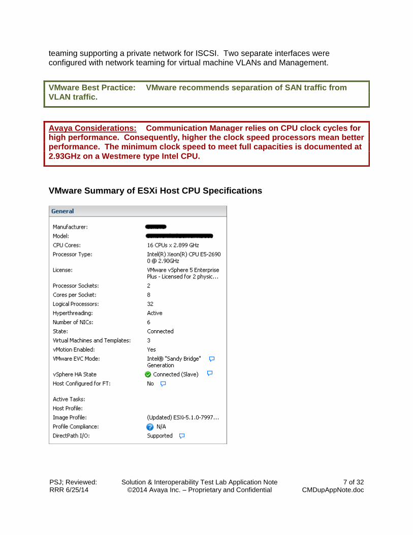
VMware Summary of ESXi Host CPU Specifications
VMware Best Practice: VMware recommends separation of SAN traffic from VLAN traffic.
Avaya Considerations: Communication Manager relies on CPU clock cycles for high performance. Consequently, higher the clock speed processors mean better performance. The minimum clock speed to meet full capacities is documented at 2.93GHz on a Westmere type Intel CPU.
PSJ; Reviewed: RRR 6/25/14
Solution & Interoperability Test Lab Application Note ©2014 Avaya Inc. – Proprietary and Confidential
8 of 32 CMDupAppNote.doc
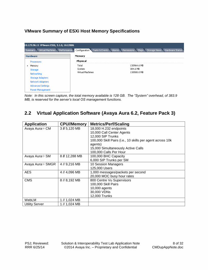
VMware Summary of ESXi Host Memory Specifications
Note: In this screen capture, the total memory available is 128 GB. The “System” overhead, of 383.9 MB, is reserved for the server’s local OS management functions.
2.2 Virtual Application Software (Avaya Aura 6.2, Feature Pack 3)
Application CPU//Memory Metrics/Perf/Scaling
Avaya Aura CM 3 // 5,120 MB 18,000 H.232 endpoints 10,000 Call Center Agents 12,000 SIP Trunks 100,000 Skill Pairs (i.e., 10 skills per agent across 10k agents) 15,000 Simultaneously Active Calls 100,000 Calls Per Hour
Avaya Aura SM 8 // 12,288 MB 100,000 BHC Capacity 6,000 SIP Trunks per SM
Avaya Aura SMGR 4 // 9,216 MB 10 Session Managers 125,000 Users
AES 4 // 4,096 MB 1,000 messages/packets per second 20,000 MOC busy hour rates
CMS 8 // 8,192 MB 800 Centre Vu Supervisors 100,000 Skill Pairs 10,000 agents 30,000 VDNs 12,000 Trunks
WebLM 1 // 1,024 MB
Utility Server 1 // 1,024 MB
PSJ; Reviewed: RRR 6/25/14
Solution & Interoperability Test Lab Application Note ©2014 Avaya Inc. – Proprietary and Confidential
9 of 32 CMDupAppNote.doc
2.3 Hardware and Software Redundancy
Redundancy of hardware components offers a high-availability disaster recovery should be considered throughout the implementation so that single component hardware failures will allow the solution to continue normal operation. After carefully architecting the hardware components, storage arrays, networking and servers for fault tolerance, the infrastructure should be administered to further support failover/recovery conditions. The following sections describe things that should be considered.
2.3.1 Servers
Server hardware should be implemented with multiple power supplies and multiple network interfaces. The power supplies should be connected to separate power sources ensuring that the server will be provided with power should a PDU or power supply fail. Multiple network interfaces should be design to space across multiple network devices ensuring that the VMs and hosts can reach the LAN in the event of a network device failure.
2.3.2 Storage Arrays
Storage arrays should be architected to tolerate drive failures and controller failures without disruption to service.
2.3.3 Network
Networking within the infrastructure should be designed such that any single device failure will not result in network impairment. Many Avaya Network devices provide this high level of resiliency.
PSJ; Reviewed: RRR 6/25/14
Solution & Interoperability Test Lab Application Note ©2014 Avaya Inc. – Proprietary and Confidential
10 of 32 CMDupAppNote.doc
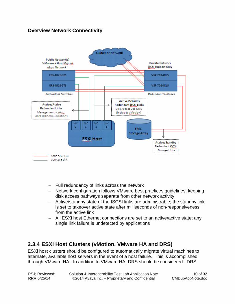
Overview Network Connectivity
Full redundancy of links across the network
Network configuration follows VMware best practices guidelines, keeping disk access pathways separate from other network activity
Active/standby state of the ISCSI links are administrable; the standby link is set to takeover active state after milliseconds of non-responsiveness from the active link
All ESXi host Ethernet connections are set to an active/active state; any single link failure is undetected by applications
2.3.4 ESXi Host Clusters (vMotion, VMware HA and DRS)
ESXi host clusters should be configured to automatically migrate virtual machines to alternate, available host servers in the event of a host failure. This is accomplished through VMware HA. In addition to VMware HA, DRS should be considered. DRS
PSJ; Reviewed: RRR 6/25/14
Solution & Interoperability Test Lab Application Note ©2014 Avaya Inc. – Proprietary and Confidential
11 of 32 CMDupAppNote.doc
provides the ability for the hosts to balance workload from the VMs across the entire cluster.
2.3.4.1 VMware vMotion
vMotion provides the ability to migrate servers from one host server to another should any server require maintenance within the cluster.
2.3.4.2 VMware HA
The typical/default configuration for VMware HA performs periodic “heartbeat” checks for hosts across the cluster. In the event of a host failure, VMware initiates virtual machine recovery in less than 15 seconds after hardware fault detection. The migration of the virtual machine (VM) to another available host happens immediately upon the timer expiry. Within seconds, the migration is complete and the VM is powered on.
2.3.4.3 Avaya Communication Manager and VMware HA
As an added level of faster disaster recovery, some Avaya Aura virtualized appliances have duplicated or redundant application capabilities. Adding VMware HA to Avaya Communication Manager Duplication allows CM to perform call preservation for active calls and subsequently allows CM duplication to be restored after VMware HA completes the migration. This feature/functionality is something not available on a traditional server deployment configuration and adds resiliency to a single data center configuration.
2.3.4.4 VMware DRS
Leveraging DRS can help avoid performance issues across a host cluster due to high resource usage from VMs. In addition, DRS provides a set of “rules” that can be leveraged for Avaya applications.
Avaya Considerations: vMotion can migrate an operational Avaya Aura virtual application to an alternate host with zero downtime, -- even during peak call traffic periods. However, it is not recommended that vMotion be performed during peak traffic to avoid performance impacts or call failures. vMotion activities are highly dependent on the virtual infrastructure.
Avaya Considerations: For a virtual appliance like Avaya Aura Communication Manager (CM), application recovery from hardware failure can take less than 30 seconds.
Avaya Considerations: Leveraging DRS rules to keep VMs located on separate hosts for failover/recovery will help ensure that duplicated CMs will reside on separate hosts.
PSJ; Reviewed: RRR 6/25/14
Solution & Interoperability Test Lab Application Note ©2014 Avaya Inc. – Proprietary and Confidential
12 of 32 CMDupAppNote.doc
3. VMware Deployment of Duplicated Communication Managers within a single VMware ESXi Host Cluster
Avaya Communication Manager can be deployed within a VMware host cluster, on separate host clusters, and even separate vCenters. For any of these types of deployments, careful attention must be made to minimize network latency between the Communication Manager VMs. According to Product Support Notice, PSN003556u (https://downloads.avaya.com/css/P8/documents/100154621), the maximum latency supported between the CM must be less than 8ms. ). For this document and validation effort, we will focus on the single host cluster deployment configuration. This will require configuration of VMware HA, DRS, networking, and storage to ensure CM will operate normally across failure conditions.
3.1 VMware Cluster Configuration
The ESXi host cluster should be configured such that there at least two hosts within a cluster and preferably more. The cluster should also be designed to provide full resources for all VMs in the event of an ESXi host failure. The following sections describe the key components and recommended configuration to support Avaya Communication Manager.
3.1.1 Cluster Networking Considerations
Communication Manager requires a minimum of two separate networks. One is used for the processor Ethernet interface and one is used for duplication. The duplication network should be a private VLAN between the Communication Managers. When there are more than a single pair of Duplicated Communication Managers within the same cluster, networking must be designed to support low latency, high traffic conditions.
3.1.2 Host Networking
The host should leverage at least two physical network interfaces for VM VLAN traffic. More can be used if the physical interfaces are available. The minimum bandwidth for each of the physical server interfaces is 1Gbs. For this configuration, we will focus on how to leverage two physical interfaces.
PSJ; Reviewed: RRR 6/25/14
Solution & Interoperability Test Lab Application Note ©2014 Avaya Inc. – Proprietary and Confidential
13 of 32 CMDupAppNote.doc
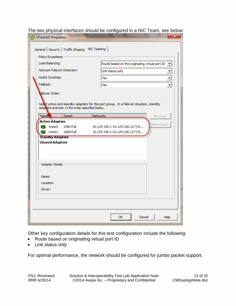
The two physical interfaces should be configured in a NIC Team, see below:
Other key configuration details for this test configuration include the following:
Route based on originating virtual port ID
Link status only For optimal performance, the network should be configured for jumbo packet support.
PSJ; Reviewed: RRR 6/25/14
Solution & Interoperability Test Lab Application Note ©2014 Avaya Inc. – Proprietary and Confidential
14 of 32 CMDupAppNote.doc
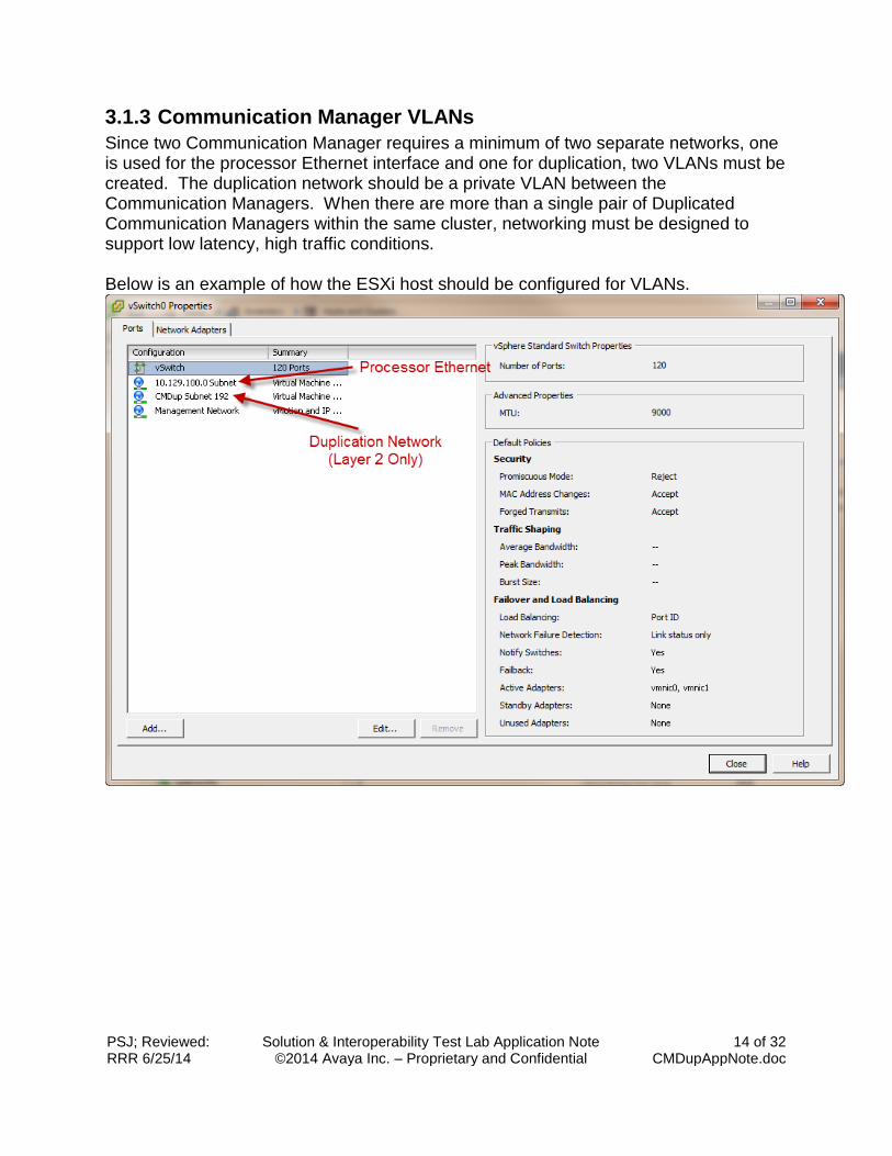
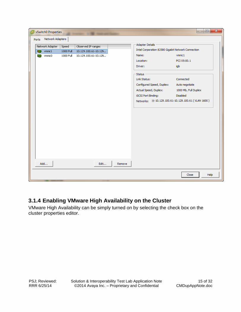
3.1.3 Communication Manager VLANs
Since two Communication Manager requires a minimum of two separate networks, one is used for the processor Ethernet interface and one for duplication, two VLANs must be created. The duplication network should be a private VLAN between the Communication Managers. When there are more than a single pair of Duplicated Communication Managers within the same cluster, networking must be designed to support low latency, high traffic conditions. Below is an example of how the ESXi host should be configured for VLANs.
PSJ; Reviewed: RRR 6/25/14
Solution & Interoperability Test Lab Application Note ©2014 Avaya Inc. – Proprietary and Confidential
15 of 32 CMDupAppNote.doc
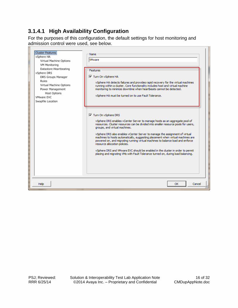
3.1.4 Enabling VMware High Availability on the Cluster
VMware High Availability can be simply turned on by selecting the check box on the cluster properties editor.
PSJ; Reviewed: RRR 6/25/14
Solution & Interoperability Test Lab Application Note ©2014 Avaya Inc. – Proprietary and Confidential
16 of 32 CMDupAppNote.doc
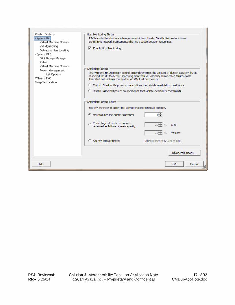
3.1.4.1 High Availability Configuration
For the purposes of this configuration, the default settings for host monitoring and admission control were used, see below.
PSJ; Reviewed: RRR 6/25/14
Solution & Interoperability Test Lab Application Note ©2014 Avaya Inc. – Proprietary and Confidential
17 of 32 CMDupAppNote.doc
PSJ; Reviewed: RRR 6/25/14
Solution & Interoperability Test Lab Application Note ©2014 Avaya Inc. – Proprietary and Confidential
18 of 32 CMDupAppNote.doc
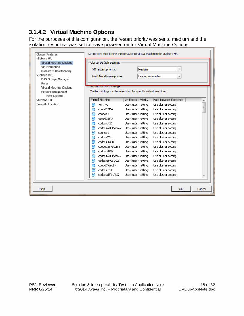
3.1.4.2 Virtual Machine Options
For the purposes of this configuration, the restart priority was set to medium and the isolation response was set to leave powered on for Virtual Machine Options.
PSJ; Reviewed: RRR 6/25/14
Solution & Interoperability Test Lab Application Note ©2014 Avaya Inc. – Proprietary and Confidential
19 of 32 CMDupAppNote.doc
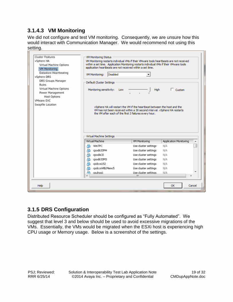
3.1.4.3 VM Monitoring
We did not configure and test VM monitoring. Consequently, we are unsure how this would interact with Communication Manager. We would recommend not using this setting.
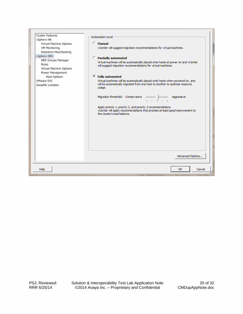
3.1.5 DRS Configuration
Distributed Resource Scheduler should be configured as “Fully Automated”. We suggest that level 3 and below should be used to avoid excessive migrations of the VMs. Essentially, the VMs would be migrated when the ESXi host is experiencing high CPU usage or Memory usage. Below is a screenshot of the settings.
PSJ; Reviewed: RRR 6/25/14
Solution & Interoperability Test Lab Application Note ©2014 Avaya Inc. – Proprietary and Confidential
20 of 32 CMDupAppNote.doc
PSJ; Reviewed: RRR 6/25/14
Solution & Interoperability Test Lab Application Note ©2014 Avaya Inc. – Proprietary and Confidential
21 of 32 CMDupAppNote.doc
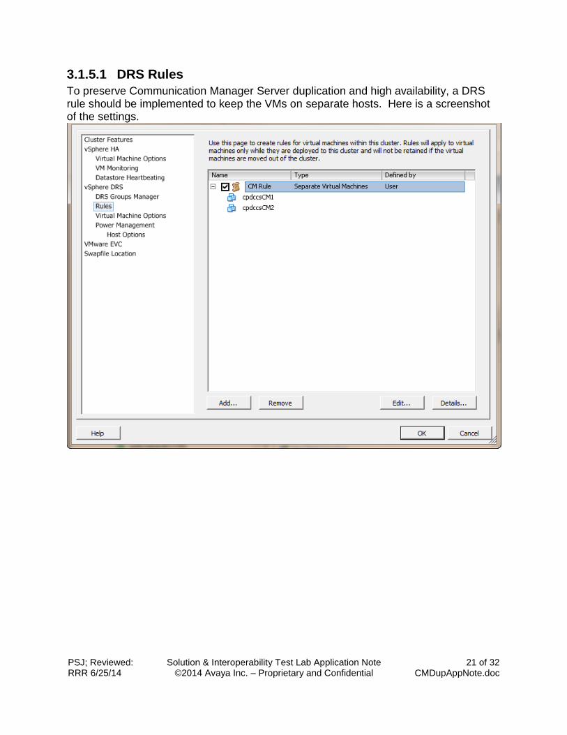
3.1.5.1 DRS Rules
To preserve Communication Manager Server duplication and high availability, a DRS rule should be implemented to keep the VMs on separate hosts. Here is a screenshot of the settings.
PSJ; Reviewed: RRR 6/25/14
Solution & Interoperability Test Lab Application Note ©2014 Avaya Inc. – Proprietary and Confidential
22 of 32 CMDupAppNote.doc
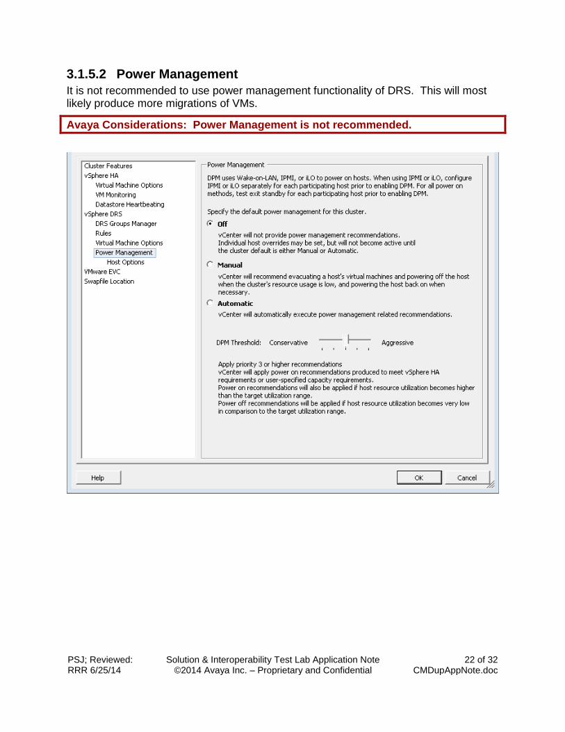
3.1.5.2 Power Management
It is not recommended to use power management functionality of DRS. This will most likely produce more migrations of VMs.
Avaya Considerations: Power Management is not recommended.
PSJ; Reviewed: RRR 6/25/14
Solution & Interoperability Test Lab Application Note ©2014 Avaya Inc. – Proprietary and Confidential
23 of 32 CMDupAppNote.doc
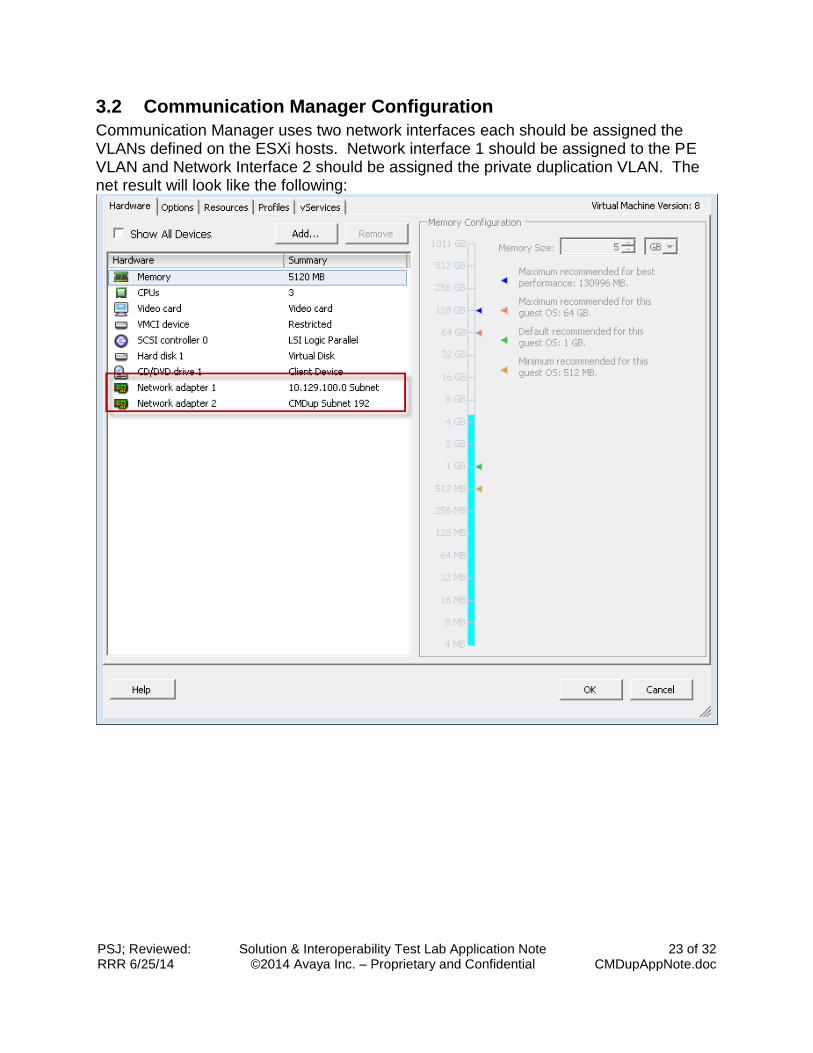
3.2 Communication Manager Configuration
Communication Manager uses two network interfaces each should be assigned the VLANs defined on the ESXi hosts. Network interface 1 should be assigned to the PE VLAN and Network Interface 2 should be assigned the private duplication VLAN. The net result will look like the following:
PSJ; Reviewed: RRR 6/25/14
Solution & Interoperability Test Lab Application Note ©2014 Avaya Inc. – Proprietary and Confidential
24 of 32 CMDupAppNote.doc
3.2.1 Communication Manager VLANs
The Processor Ethernet (PE) VLAN should be fully routable. Both Communications Managers should be on the same VLAN for PE to operate correctly. The Duplication VLAN is not routable and should be configured as a layer 2 network only. This means the network equipment supporting the VMware infrastructure must be configured to support the layer 2 VLAN. The minimum bandwidth for adequate performance of the PE and Duplication VLANs is 1Gbs. The network must also be configured for low latency and generally less than 8ms.
Avaya Considerations: Communication Manager Network interfaces must be given adequate bandwidth based on high traffic rates (1Gbs) and prioritization. Consideration of these conditions across the infrastructure should be considered during the design of the virtual environment hosting the VMs.
3.2.2 Communication Manager DRS Rules
See section 3.1.5 1 for DRS rules for the cluster.
Avaya Considerations: To preserve Communication Manager Server duplication and high availability, a DRS rule should be implemented to keep the VMs on separate hosts.
PSJ; Reviewed: RRR 6/25/14
Solution & Interoperability Test Lab Application Note ©2014 Avaya Inc. – Proprietary and Confidential
25 of 32 CMDupAppNote.doc
4. Solution Testing Test execution was primarily aligned to 3 areas: performance, reliability and recovery. Throughout the testing, we were assessing the performance characteristics of Communication Manager.
4.1 Application Administration Avaya Aura Communication Manager
1. IP Direct enabled on all levels (enables device <-> device connectivity off TDM bus) 2. BCMS measuring 3,000 trunks (capacity maximum; function internal to CM) 3. BCMS measuring all VDNs and skills being used across the call flow 4. 10,000 agents administered with 10 skills assigned per agent 5. 125,000 calls per hour
Call Management System
1. 100,000 agent skill pairs 2. 800 supervisor report users 3. Each supervisor administered for 3 real time reports of skills, VDNs and trunks 4. All VDNs, trunks and skills used are measured externally in CM for CMS data collection
Avaya Aura System Manager
1. Single Domain 2. All SIP trunks administered as TLS encryption 3. 2 Domain Locations – external and internal to Collaboration Pod
Application Enablement Services
1. 10,000 MOC users administered 2. CLAN link to 3
rd Part Routing application monitoring all 10,000 agents
3. TSAPI link to MOC traffic generation tool supporting all 10,000 extension users
4.2 Test Result/Observations VMware HA/DRS:
For vSphere 5.1, VMware HA does not check DRS rules before migrating a VM to a new host during a host failure. During testing, we observed that VMware migrated the secondary Communication Manager to the same ESXi host as the active Communication Manager despite the DRS rule to keep the VMs on separate hosts. Within a second of the VMWare HA migration, DRS found the CM and migrated the Communication Manager to a different host.
PSJ; Reviewed: RRR 6/25/14
Solution & Interoperability Test Lab Application Note ©2014 Avaya Inc. – Proprietary and Confidential
26 of 32 CMDupAppNote.doc
4.3 Traffic Generation
Call Generation Call traffic is supported by an Avaya developed tool to closely emulate real endpoint/user activity. The Traffic and Regression Test System (TARTS), uses the same firmware and software protocols that real Avaya H.323 endpoints use in production. Endpoint emulation also aligns with real phone button templates, such that TARTS can activate feature buttons as a real user might, as well as validate lamp and display updates for behavioral and character correctness. As the automated endpoints generate DTMF digits to initiate call traffic, TARTS begins to monitor responses within associated call processing scripts. If the response times are within the tolerance values administered in the TARTS scripts, the call activity is reported as a passed activity; likewise, if the response times exceed the tolerance values, the call is registered as failed. For example, a tolerance level of 2500ms is administered for time to detect dial tone and 3000ms is administered for talk path cut through; as long as the dial tone and two-way talk path is confirmed within their administered time frames, the call activity is passed. If even one of the administered criteria is not met, the automated call is reported as failed. When assessing the final passed versus failed activity, the call failure rate – the number of failed calls per hour, must fall within specified criteria for the scenario to be considered a success. All Avaya offers must attain a call failure rate (CFR) of < .0004, or < 4 in 10,000 calls, to be worthy of product general availability.
4.4 Steady-State Performance of Communication Manager
Performance was assessed throughout the testing. Avaya Aura applications as well as the VMware infrastructure were monitored for CPU, Ram, Network, and SAN consumption. Traffic levels were varied throughout the test to observe differences in performance. Certain aspects of background maintenance and system management are considered part of the performance assessment. Administrative, debug or search commands that demand CPU cycles, or maintenance activities that contend for the virtualization resources were not imposed during the testing. As traffic was running for each scenario, TARTS scripts were administered to activate vu-stats and evaluate q-lamp updates. This activity added additional CPU and messaging across CM and network applications. Scripts also transferred 10% of the call traffic as outbound trunk traffic to exercise and evaluate that core functionality under load.
PSJ; Reviewed: RRR 6/25/14
Solution & Interoperability Test Lab Application Note ©2014 Avaya Inc. – Proprietary and Confidential
27 of 32 CMDupAppNote.doc
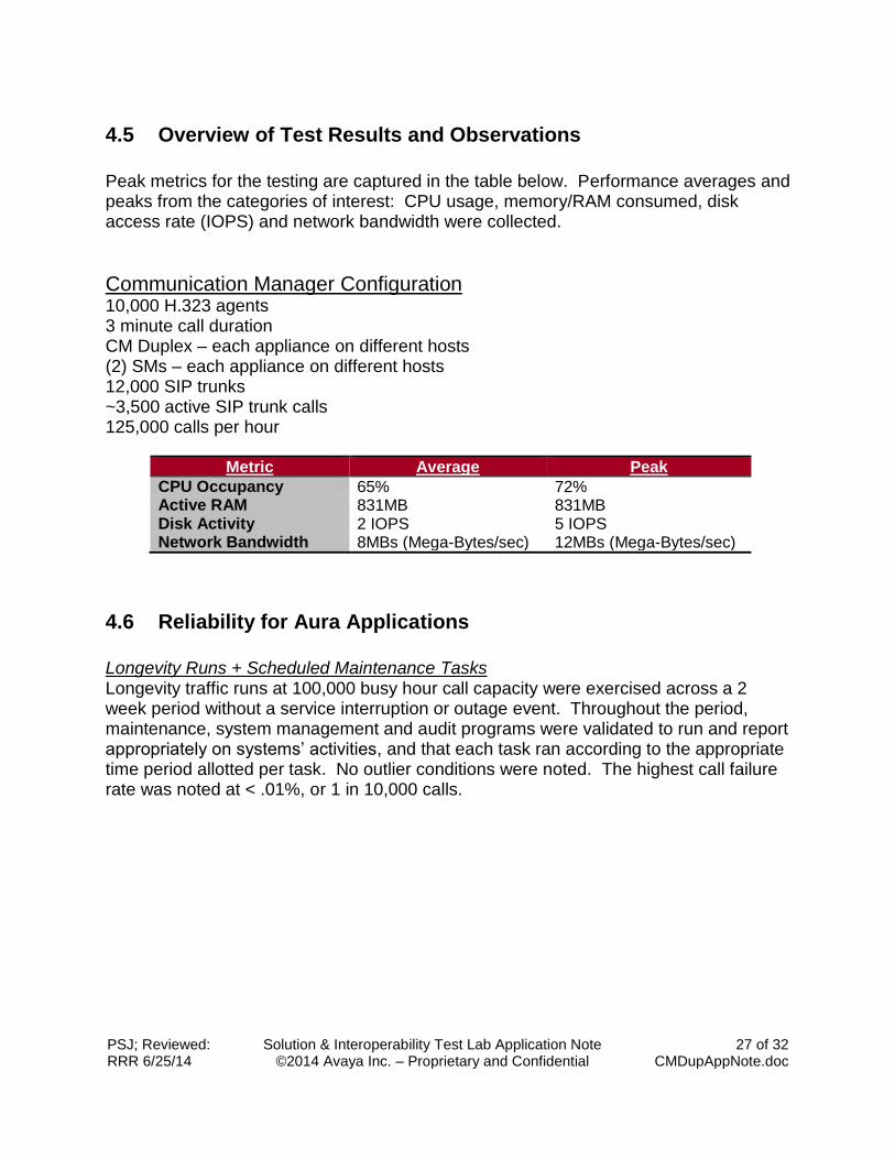
4.5 Overview of Test Results and Observations
Peak metrics for the testing are captured in the table below. Performance averages and peaks from the categories of interest: CPU usage, memory/RAM consumed, disk access rate (IOPS) and network bandwidth were collected.
Communication Manager Configuration 10,000 H.323 agents 3 minute call duration CM Duplex – each appliance on different hosts (2) SMs – each appliance on different hosts 12,000 SIP trunks ~3,500 active SIP trunk calls 125,000 calls per hour
Metric Average Peak
CPU Occupancy 65% 72% Active RAM 831MB 831MB Disk Activity 2 IOPS 5 IOPS Network Bandwidth 8MBs (Mega-Bytes/sec) 12MBs (Mega-Bytes/sec)
4.6 Reliability for Aura Applications
Longevity Runs + Scheduled Maintenance Tasks Longevity traffic runs at 100,000 busy hour call capacity were exercised across a 2 week period without a service interruption or outage event. Throughout the period, maintenance, system management and audit programs were validated to run and report appropriately on systems’ activities, and that each task ran according to the appropriate time period allotted per task. No outlier conditions were noted. The highest call failure rate was noted at < .01%, or 1 in 10,000 calls.
PSJ; Reviewed: RRR 6/25/14
Solution & Interoperability Test Lab Application Note ©2014 Avaya Inc. – Proprietary and Confidential
28 of 32 CMDupAppNote.doc
Network Impairment While running traffic at 100,000 busy hour call rate, up to 100ms roundtrip delay was injected across the CM duplication link – between the active and standby servers, impacting data shadowing processes. No impact to call processing or solution stability was noted during the 72 hour exercise. Maintenance, error and alarm logs were reviewed on CM; no impact was reported.
Overload Conditions Avaya Aura Communication Manager Call traffic was raised > 125,000 busy hour call rates until CM reported ~ 70% CPU. It was not possible, using only the call load available, to push the application into an official overload CPU capacity: 92% CPU for > 20 seconds. The network impairment between active and standby CM servers was then re-introduced, this time at 750ms roundtrip delay. This activity caused more consistent packet retransmissions and an added burden to overall CM processing as the duplication activity – a priority for the CM application, worked harder to maintain current call activity shadowing between servers. Additional call transfers and endpoint feature button activation were also added into the mix; the CM CPU would then occasionally spike into overload, for a few seconds at a time. Despite the burdens and obstacles placed into the CM configuration, call processing remained steady and successful. CM maintenance and error logs reported the overload conditions appropriately and in a timely fashion. The only impacts noticed were from the TARTS performance reports, showing an additional 300-500ms for endpoints to access dial tone and receive button press responses; none of these delays caused call processing to fail.
4.7 DRS Balance Due to Excessive CPU Occupancy on the ESXi Host
A simple CPU utilization tool, cpu hog, was developed as an application and added to the ESXi host, application server 1, supporting most of the solution and application activity. The goal of the tool was to demand CPU from the host until the server went into an overload state or reacted to stop the overload conditions. To monitor the behaviors of the applications and the impact of the tool, the following reports were left open and assessed.
vCenter performance tools
Internal appliance performance and error reports
from the ESXi host, the top command
Avaya Consideration: 8ms network delay is supported even though this test was performed at 100ms for normal operation activity.
PSJ; Reviewed: RRR 6/25/14
Solution & Interoperability Test Lab Application Note ©2014 Avaya Inc. – Proprietary and Confidential
29 of 32 CMDupAppNote.doc
While call traffic was running at 100,000 busy hour call rate, the cpu hog tool was activated. CPU demands escalated quickly, and within 10 seconds, the ESXi host’s total CPU was raised to 70-75%. Within a few additional seconds, the DRS function determined the tool required facilities that could be better serviced on a less active host; the cpu hog applications was migrated to another ESXi host that had available CPU to consistently support the demand. No impact to call processing was observed or reported during the activity.
4.8 DRS Balance Due to Excessive RAM Usage on the ESXi Host
Similar to the DRS balance for excessive CPU occupancy on a host, another application tool was developed, mem hog. Memory hog was deployed on the ESXi host and was designed to utilize lots of ESXi host memory. Monitoring of the behaviors was performed from the following tools.
vCenter performance tools
Internal appliance performance and error reports
from the ESXi host, the top command While call traffic was running at 100,000 busy hour call rate, the mem hog tool was activated. RAM consumption escalated quickly, and within several minutes, the ESXi host’s total RAM usage was increased to above 80%. Within a few additional minutes, DRS functionality determined VMs could be better serviced on a less active host; the smaller VMs were migrated to another ESXi host that had less RAM consumption. No impact to call processing was observed or reported during the activity.
4.9 Recovery of Communication Manager for an ESXi Host Failure
ESXi Host Power Failure: The active ESXi host supporting the primary call processing activity (Active Communication Manager) was powered off while traffic loads were running at a 100,000 calls per hour. The following bullet list represents the sequence of activities that followed the power off process.
The standby CM takes over call processing activity in less than 4 seconds (for this test it interchanged in ~50ms). The standby CM is now the active CM.
VMware detects the loss of the host and reports such via the vCenter Tasks & Events tab (at the Data Center viewing level)
At ~10 seconds, VMware HA functionality migrated the virtual applications to an alternate available host
PSJ; Reviewed: RRR 6/25/14
Solution & Interoperability Test Lab Application Note ©2014 Avaya Inc. – Proprietary and Confidential
30 of 32 CMDupAppNote.doc
Once the migration of a VM is complete (1-2 seconds), the HA process powered up the Communication Manager VM.
After the CM is booted, it becomes the standby CM and operates in normal duplication mode. This process took less than 2 minutes.
Throughout the event call processing continued normally and stable calls remained active.
To confirm the reliability of recovered communications across the solution, a CM server interchange was demanded. - The activity succeeded immediately, per request - No impact to call processing was noted
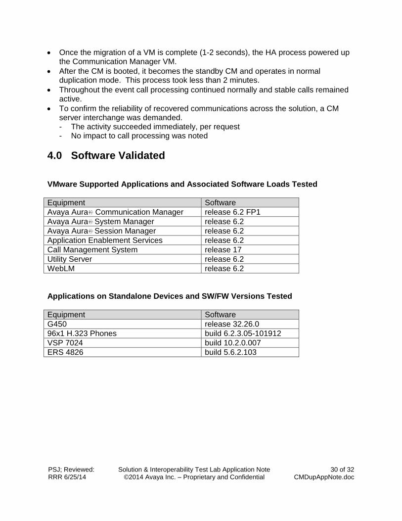
4.0 Software Validated VMware Supported Applications and Associated Software Loads Tested
Equipment Software
Avaya Aura Communication Manager release 6.2 FP1
Avaya Aura System Manager release 6.2
Avaya Aura Session Manager release 6.2
Application Enablement Services release 6.2
Call Management System release 17
Utility Server release 6.2
WebLM release 6.2
Applications on Standalone Devices and SW/FW Versions Tested
Equipment Software
G450 release 32.26.0
96x1 H.323 Phones build 6.2.3.05-101912
VSP 7024 build 10.2.0.007
ERS 4826 build 5.6.2.103
PSJ; Reviewed: RRR 6/25/14
Solution & Interoperability Test Lab Application Note ©2014 Avaya Inc. – Proprietary and Confidential
31 of 32 CMDupAppNote.doc
5.0 Conclusions/Recommendations Avaya Aura Communication Manager can be supported with vMotion, VMware
High Availability, and Distributed Resource Scheduler.
Throughout testing, vMotion did not result in any observed call failures.
VMware High Availability was demonstrated to preserve call states and recover full duplication upon a server failure.
DRS rules should be created to ensure Communication Manager VMs reside on separate hosts thereby maintaining server duplication in the event of an ESXi host failure.
Virtual networks (VLANs) can be leveraged for the Process Ethernet and the Duplication network interfaces as long as the network devices provide low latency high bandwidth capabilities.
PSJ; Reviewed: RRR 6/25/14
Solution & Interoperability Test Lab Application Note ©2014 Avaya Inc. – Proprietary and Confidential
32 of 32 CMDupAppNote.doc
6.0 Authors, Developers, and Testers Phil James Kathryn Anders Carolina Creus Dave Kleidon
©2014 Avaya Inc. All Rights Reserved The information contained in this document is the exclusive property of Avaya and should not be disclosed to any third party without the written consent of Avaya. Avaya and the Avaya Logo are trademarks of Avaya Inc. All trademarks identified by ® and ™ are registered trademarks or trademarks, respectively, of Avaya Inc. All other trademarks are the property of their respective owners. The information provided in these Application Notes is subject to change without notice. The configurations, technical data, and recommendations provided in these Application Notes are believed to be accurate and dependable, but are presented without express or implied warranty. Users are responsible for their application of any products specified in these Application Notes.