Embed Size (px)
Citation preview

Approved Continuing Education for Licensed Professional Engineers
Durability by Design
Five (5) Continuing Education Hours
Course #CV1105
EZ-pdh.com Ezekiel Enterprises, LLC
301 Mission Dr. Unit 571 New Smyrna Beach, FL 32170
800-433-1487 [email protected]

Durability by Design Ezekiel Enterprises, LLC
ii
Course Description:
The Durability by Design course satisfies five (5) hours of
professional development.
The course is designed as a distance learning course that presents
topics of durability in residential construction.
Objectives:
The primary objective of this course is to enable the student to
understand the principles of durability in designing residential
structures and to understand the many elements encountered which
negatively affect durability.
Grading:
Students must achieve a minimum score of 70% on the online quiz
to pass this course. The quiz may be taken as many times as
necessary to successful pass and complete the course.
A copy of the quiz questions are attached to last pages of this
document.

Durability by Design Ezekiel Enterprises, LLC
iii
Table of Contents Durability by Design
Ch. 1 Introduction ........................................................... 1
Ch. 2 Durability Concepts ................................................ 6
Ch. 3 Ground and Surface Water .................................... 13
Ch. 4 Rain and Water Vapor .......................................... 22
Ch. 5 HVAC and Plumbing ............................................. 77
Ch. 6 Sunlight .............................................................. 94
Ch. 7 Insects .............................................................. 102
Ch. 8 Decay and Corrosion .......................................... 109
Ch. 9 Natural Hazards ................................................. 114
Appendix A Durability Checklist .................................. 127
Quiz Questions ........................................... 133

Durability by Design 1
CHAPTER 1—INTRODUCTION
1.1 General A sustainable future for America requires sustainable
buildings. And sustainable buildings must be durable
buildings. And while the mention of the word
“sustainability” is usually a trigger for designers and
builders to think about energy efficiency and green
building materials, building durability cannot be
overlooked as a critical pillar of sustainability. Simply put,
a home with a fantastic thermal envelope and high
efficiency mechanical systems which is also riddled with
prematurely failing building materials and systems is NOT
green or sustainable. Green and sustainable homes must
be durable homes.
But what do we really mean by the goal of a “durable”
building? For this course, “durability” is defined as the
ability of a material, system, or building to maintain its
intended function for its intended life-expectancy with
intended levels of maintenance in intended conditions of
use. Obviously this definition may take on different
meanings for different groups (e.g., builders,
homeowners, manufacturers), demonstrating that
communication and education are also key aspects that
affect durability.
Addressing durability shouldn’t be a pursuit of extremes,
but rather a cost-effectiveness strategy for both initial
and longer-term (i.e., maintenance, replacement) costs.
Designing a home to be “ultra” durable can add so much
cost it makes the home unaffordable. Erring in the other
direction can result in poor performance and loss of
business reputation—including homeowner complaints,
unsafe or unhealthy living conditions, and excessive
maintenance and repair costs.
Why Is Durability So Important?
Avoidance of short-term durability or
performance problems (i.e., callbacks) is
important to the builder’s and designer’s
reputation, risk management, and business
profitability.
The long-term durability of a home is important
to retaining its investment value as well as its
continued function as a safe, healthy, and
aesthetic living environment.
Sustainability policies and programs focused on
energy efficiency or green homes are wasted
efforts if these homes aren’t durable.
There’s nothing green about a home which ends up like this. Image Source: U.S. HUD 2005. New Orleans, LA.
Poor durability increases the operating and
maintenance cost of home ownership.
Failure to meet reasonable expectations for
durability increases liability exposure.
People don’t like maintenance (i.e., high
durability and low maintenance are important
sales and purchasing factors).
New products designed or installed without
adequately considering durability can
prematurely fail, leading to both customer
dissatisfaction and manufacturer losses.
Ezekiel Enterprises, LLC

2 Durability by Design
But, “you get what you pay for!” Right? While this may often be the case, it’s important to realize that
there are many design and construction practices that have zero or minimal construction cost impacts,
while offering significant durability benefits. These benefits may be measured in terms of maintenance,
repair, general function of the home and its component parts over time, enhanced business reputation,
and customer satisfaction. Moreover, many such practices are well-known and don’t need to be re-
invented, but only communicated effectively to the builder, designer, and consumer.
This course strives to reinforce both “tried and true” durability practices which apply today just like they
did a generation ago (e.g., best practices for gutter sizing), along with measures that address the housing
industry’s rapid evolution in terms of materials and construction practices (e.g., dew point management
in high R-value walls). In both cases, the course aims to focus on practical solutions to significant,
recurring durability problems.
1.2 Integrated Design—Making Durability Part of the Process Traditional homebuilding has had an approach similar an Olympic relay, where the baton is passed from
one runner to the next until the finish line is crossed. With homebuilding, this used to be the method
favored by most to accomplish the task of turning over a home to a new homeowner. With design and
construction of homes becoming more complex, integrated design has quickly moved from a good
practice to a necessity for homebuilders.
Why? Like it or not, new homes today function as a system of interconnected parts. Driven in large part by
energy requirements found in building codes, homes today simply “work” differently from they did before.
For example, the air sealing and insulation levels of the building envelope greatly affect the HVAC design,
as well as the potential for a small, chronic window leak to actually dry out. The strategy used to meet wall
insulation requirements also affects the weather resistant barrier (WRB) selection; window flashing, air
sealing, wall bracing methods; and even the potential for condensation to form in the wall. As Figure 1–1
illustrates, a home’s durability is intricately wrapped up in these interconnected systems. To some extent
these systems have always had connections. The difference is that in today’s new homes the “web” is
woven much more tightly, and a change in one system “pulls” directly on other parts of the home.
Ezekiel Enterprises, LLC

Durability by Design 3
Figure 1–1: The Web of Durability
At the core of durability are three of the major systems in a house: envelope, structure, and mechanicals. Each of
these affects the other. On the periphery are the forces that can also affect each of these core systems. Builders
and designers must recognize that each decision made affects (and
should inform) many other systems or decisions.
Integrative design can bring order and predictability to this web.
What does this mean to the builder? Providing leadership and facilitating effective communications. Similar to assembling a
design team, assembling a construction team of like-minded individuals or companies interested in providing a superior product to the consumer would be one of the first and foremost tasks.
Many integrated design issues which
cascade across different trade
partners are highlighted throughout
this course. Why? Because they can
have a big impact on a home’s
durability! Look for text boxes labeled
“Integrated Design and Construction”
throughout the course.
Ezekiel Enterprises, LLC

4 Durability by Design
The builder gets the dialogue started before the project starts. As part of this dialogue the
interconnections we see in Figure 1–1 are discussed, and implications for the contractors’ roles and work
scopes are identified. The cast of trade partners involved in this process should reflect the project’s goals.
For example, in a residential project with the objective of excellent building durability and a high level of
energy efficiency, these goals necessarily involve trades like foundation, framing, HVAC, insulation/air
sealing, windows/siding, and roofing. An energy consultant would also be involved. As a result of this
deliberate communication process and adjusting work scopes and schedules, unexpected surprises such as
delays or change orders are reduced, and durability and overall home performance improve. Applying this
approach to both the design process and the construction process will help to ensure that a safe, strong,
efficient, durable home will be the end result.
1.3 Course Overview This course is arranged in the most practical and user-friendly way possible. However, as the “durability
web” figure shows, there are many interrelated topics, which make any arrangement of information on
durability a bit challenging. To the degree possible, redundancy in content is minimized and interrelated
topics or discussions are crossreferenced so that readers can seek additional information needed with
relative ease. Appendix A also contains a cross-cutting durability checklist for builders and designers.
The scope of this course cuts across the “durability drivers” shown listed below. Note that the building
envelope and structure are not listed separately as they’re integrated across all of the drivers.
An effort has also been made to include geographically based data and other technical information that
allows the reader to quickly determine the relevance of a particular durability issue to local conditions or
requirements.
Lastly, it is vital for the reader to note that this course is just that—a course and that all locally applicable
building code regulations apply and take precedence. Likewise, manufacturer recommendations should
be followed and take precedence. This course is a collection of important durability measures and
practices, however it is by no means comprehensive or all-inclusive. For that reason, each chapter also
contains links to additional resources which will go deeper into a particular topic.
Ezekiel Enterprises, LLC

Durability by Design 5
Ground and Surface Water Chapter 3
Rain and Water Vapor Chapter 4
Mechanical Systems Chapter 5
Sunlight Chapter 6
Insects Chapter 7
Decay and Corrosion Chapter 8
Natural Hazards Chapter 9
Durability Measures—Minimum Code Requirements or Best Practices? As for the actual durability measures in Chapters 3 through 9, some are simply basic code requirements. Why? Because even basic code requirements can be critical details to get right, and simply focusing on
them in the design and specification phase can offer a big durability payoff! In fact, many “above-code” programs which label and distinguish homes in the market include a number of requirements which are
simply code requirements. In most cases, these programs include them as requirements because a third party is verifying that they are applied.
Recommended measures may also cover issues not directly covered by codes or standards, yet are critical for durability. Despite the extensive framework of requirements found in building codes like the
International Residential Code (IRC), there are often gaps in the details when applying the code to a specific application or local condition.
Ezekiel Enterprises, LLC

6 Durability by Design
CHAPTER 2—DURABILITY CONCEPTS
2.1 General In this chapter, some fundamental concepts of durability related to the design of residential buildings are addressed. This background information is intended to establish a baseline of understanding and to
introduce concepts important to developing a realistic perspective on durability. It is important to appreciate the significance of durability when attempting to balance or optimize many factors that define
the realities of construction and the service life of a building.
Before discussing the concept of durability, some unrealistic notions surrounding the topic should be
dispelled:
Durability does not mean perfection, but it does require diligent effort for continual improvement.
Durability does not mean that things should last forever, but it does require that reasonable life
expectancies are achieved or exceeded.
Durability doesn’t mean that all problems are foreseeable for designers; there are many examples
of problems beyond the prediction of designers, such as polybutylene plumbing and initial EIFS systems.
Durability doesn’t mean fail-safe installation, but it does demand a level of care that matches skill
levels and quality of workmanship with the nature of the work being performed and consequences of installation defects.
Simply put, durability is a multifaceted challenge. It involves nearly all aspects of construction, including planning, design, material specification, construction management, work force skill, and quality control.
This particular document addresses the residential building design and specification phases of the construction cycle, although several topics naturally stray into work site issues and quality control.
Ezekiel Enterprises, LLC

Durability by Design 7
To fail to plan for durability is a plan to fail. For example, durability problems are frequently
associated with avoidable construction defects. A 2007 ASHRAE study found that out of 17,000
construction defect claims, 69% were the result of moisture-related defects in construction of the
building envelope.1 In recent years there have been
settlements costing U.S. homebuilders tens of
millions of dollars to repair and correct water damage caused by construction defects.
Furthermore, the USDA Forest Product Laboratory reports that “termites invade more than 600,000
homes and cause over $1.5 billion in damage
annually.”2 We could go on with more statistics and
figures, but clearly there is plenty of evidence that the factors influencing durability really do matter,
and that there is plenty of room for improvement.
While builders and designers cannot foresee all
durability issues, where they can affect better durability is in informed selection, integration, and
application of components, materials, and building systems. This process is far from simple as an ever-
changing menu of products and systems is used to optimize cost, performance, aesthetics and
consumer appeal, code compliance, and constructability. Further, a change to any one of these factors (e.g., a major uptick in material prices
or a code change) can trigger a change from “Assembly A” to “Assembly B.” If Assembly B wasn’t
vetted for how the new product would affect the home’s durability, the builder has just incurred
additional risk. These material changes also cannot
1 Grosskopf, K., Oppenheim, P., and Brennan, T. (2008). Preventing Defect Claims in Hot, Humid Climates. ASHRAE Journal, July 2008. www.ashrae.org 2 “Wood You Believe: Insect and Marine Borer Edition”, U.S. Forest Products Lab Newsline, Vol. 13, Issue 2, 2013. www.fpl.fs.fed.us.
“Taking Credit” for Great Durability
In today’s housing market builders and their design
team often ask how they can get recognition in the
market for going “beyond code” in energy
efficiency, durability, or disaster resistance. These
are critical attributes for long-term performance
and the experience of living in the home—but
they’re also not the shiny countertops or inviting
floor plans buyers are drawn to….so how does a
builder “get credit”?
This is a great question and one worth figuring
out.
Leading builders and designers who go above and
beyond code must be able to market the superior
performance of their product. Here are some of
their strategies for gaining this market recognition:
Leverage third party labeling programs – so the
builder doesn’t have to say “trust me” but rather
the home has an independent certification.
Examples of third party labeling programs with
durability measures include ENERGY STAR
Homes; DOE Zero Energy Ready Home; and
Fortified Home.
If your homes include measures which reduce
lender risk via lower energy bills, reduced
insurance premiums, or other mechanisms –
provide as much documentation as possible to
the lender and the appraiser. Also upload as
much certification information as possible to the
local real estate listing service (e.g., MLS).
Use consumer-friendly tools to draw attention to
the hidden features of the home. Example
strategies include creating a checklist of moisture
management measures for your home versus a
minimum code or existing home, or creating a
transparent wall cutaway, or “truth wall,”
showing the internal components of the
envelope.
Ezekiel Enterprises, LLC
8 Durability by Design
be disassociated from changes that occur in the labor force. New materials or methods introduced into a
construction process require a means of not only understanding the system or product, but also training of
affected trades and quality control. Further downstream with the homeowner, these changes may also
place new demands or expectations on home maintenance.
How can a builder take action today and better prepare for the durability challenges of tomorrow? This
chapter and the remainder of this course offer answers to this question. Section 2.2 defines durability
and provides resources to engage both the builder and consumer in the pursuit of durability. Section 2.3
provides a brief overview of common durability problems in the present or recent past—which serve as
lessons to apply better strategies in building the homes of tomorrow.
2.2 Durability Defined Durability is the ability of a material, product, or building to maintain its intended function for its intended
life-expectancy with intended levels of maintenance in intended conditions of use. There’s ample “wiggle
room” in this definition admittedly, but ultimately what is built must work as expected, or as nearly so as
practicable.
What is a reasonable expectation or goal for durability? It depends.
It depends on how much it costs. It depends on the expectations of the end user and the long-term
investment value of the product. It depends on the local climate. It also depends on expected norms when
the end user is not intimately involved with or knowledgeable of various design decisions and their
implications. It also depends, of course, on the material or building system itself.
For example, a house is expected to last for 75 years or more with normal maintenance and replacement
of various components. Current building rates are actually at a pace where homes may need to be in use
well beyond a 75 year replacement cycle. “Normal maintenance” is needed to reach these longevity goals,
but what one person considers normal maintenance may be perceived differently by another. Durability is,
therefore, an exercise in the management of expectations as well as an application of technology.
For this reason, some builders and designers make significant efforts to inform their clients and trade
partners about reasonable expectations for the durability, performance, maintenance, and operation of a
home. Some references to help in this matter include:
Healthy Homes Maintenance Checklist:
http://www.hud.gov/offices/lead/library/hhi/Healthy_Housing_CheckList.pdf
Home Maintenance Made Easy: What To Do, When to Do It, When To Call For Help:
https://builderbooks.com/book/home-buyers-owners/home-maintenance-made-easy-what-
to-do-when-to-do-it-when-to-call-for-help.html
Moisture and Air, Householder’s Guide—Problems and Remedies, Canada Mortgage Housing
Corporation, 2004 (rev. 2012), http://www.cmhc.ca
Ezekiel Enterprises, LLC

Durability by Design 9
In addition to this essential task of helping homeowners understand basic maintenance responsibilities
and expectations, a growing number of builders are also “taking credit” for the enhanced durability
measures they incorporate (see text box on page 7).
2.3 Common Durability Issues Durability must be considered at all phases of a building’s life cycle, from the design phase (the focus
of this course) to field installation and then to the long-term maintenance of a home. While a home’s
builder and designer cannot always assure that durability-enhancing practices will be upheld
“downstream” with contractors and homeowners, many of the most common durability issues can be
positively affected by the builder and designer through selecting appropriate products, calling out key
details on plans, and applying integrated design.
So what are these “common durability issues”?
Figure 2–1: Soil Grade Slopes Towards the Foundation, Causing Water to Pool
Ezekiel Enterprises, LLC

10 Durability by Design
Figure 2–2: Non-existent Flashing Around Window, Practically Inviting Water Intrusion
According to the home inspection industry,3 these problems are among the “top 10” of home inspection
issues:
The landscape slopes toward the house (see Figure 2–1).
Lack of proper exterior water control, e.g., gutters and downspouts.
Bathroom vents exhaust into the attic.
Lack of weep holes in brick, stone veneer and weep screed in stucco.
Lack of and/or improper deck flashing.
3 The 10 Most Common Home Inspection Issues and Gaffes, ASHI Reporter, American Society of Home Inspectors, March 2014. http://www.ashireporter.org/HomeInspection/Articles/The-10-Most-Common-Home-Inspection-Issues-and-Gaffes/7596 (accessed September 2014).
Ezekiel Enterprises, LLC

Durability by Design 11
The furnace, air conditioner, fireplace, and/or dryer vent have not been serviced in the past 12 months
Mortar missing in between the brick/stone of exterior chimney.
Thus, 7 of the 10 most common home inspection issues have direct durability implications!
Key durability-related findings from a survey of code officials conducted jointly by the National Association of Home Builders (NAHB) and the International Code Council (ICC) include:
Among grading/site drainage code provisions, inadequate grading and downspout/draining controls were two of the three most common code violations
In the area of flashing, window flashing problems were the most common area for code violations
(see Figure 2–2). Further, code officials responded that 66% of the flashing problems were related to installation, as opposed to the product itself or both the product and the installation. This is
actually an improvement; in the original 2006 study, 82% of code officials felt that flashing violations were primarily installation-related.
These results on durability-related code provisions are further evidence of commonly occurring issues. And considering that the building code doesn’t give us all of the durability measures to ensure good
performance, getting the code provisions right is just a starting point.
Field surveys of older and newer homes also reveal both problems and some useful “lessons learned” for improved durability. In a 2001 durability assessment sponsored by U.S. HUD,4 findings included:
Foundation Materials & Methods: In field assessments of 1970s and 1990s houses (homes that were roughly 25 years and 5 years old at the time of the study), 57% and 78% had basement
foundations, respectively. In addition, 51% of the 1970s basement foundations used block construction whereas 73% of the 1990s basement foundations used concrete. While age is a factor
in developing foundation cracks, 65% of the block foundations experienced visible cracking while only 10% of the concrete foundations exhibited similar cracks. Furthermore, 28% of the sites with
surface depressions next to the foundation (commonly due to poor backfilling practices and settlement over time) accounted for 44% of the sites with visibly cracked foundation walls.
o Lesson learned: Build a strong foundation and ensure proper backfill compaction and surface water drainage.
Roof Overhangs: While only 40% of 1970s homes had roof overhangs of 12” or less, 82% of the
1990s homes fell into this category.
4 “Assessing Housing Durability: A Pilot Study,” U.S. Department of Housing and Urban Development, November 2001. http://www.huduser.org/portal/publications/destech/housing_durability.html (accessed September 2014).
Ezekiel Enterprises, LLC

12 Durability by Design
o Lesson learned: A trend toward less roof overhang coupled with greater frequency of two-story construction in newer homes is leading to less protection of wall assemblies
from rainwater intrusion. Greater attention to the proper execution of water-resistive barrier and flashing practices is important to offset the durability consequences of this
trend.
Clearly, there are a wide range of durability problems in America’s homes. And while moisture is certainly
the dominant driver of durability issues, other factors such as insects, sunlight, and mechanical system performance can also make or break a home’s durability over time. Thus, the chapters which follow have a
strong emphasis on moisture and also take into account the other major durability drivers.
Beyond these chapters, Appendix A provides an abbreviated durability checklist which designers and
builders should use to confirm they’re addressing key issues.
Ezekiel Enterprises, LLC

Durability by Design 13
CHAPTER 3—GROUND AND SURFACE WATER
3.1 General Nearly all building sites have the potential to experience problems with ground moisture, particularly when the water table is high or drainage is poor. Poor
site drainage and difficult site conditions, such as “loose” soils or fills, can contribute to eventual building
settlement, foundation wall cracking, and aggravated moisture problems. As residential development
continues in many markets and development space is at a premium, the luxury of selecting sites which offer good soil and surface conditions is often an amenity that’s
simply not available. Thus, this section gives recommendations that recognize the need to be
resourceful with the building lots which are available.
The objective of a foundation is to separate the building
materials and the indoor environment from the earth while also providing adequate structural support. The
following rules of thumb and recommended practices should serve to minimize the potential for durability
problems related to foundations (which are among the most common durability issues listed in Section 2.3).
3.2 Recommended Practices
3.2.1 Conduct a Preliminary Site Investigation The following actions help to identify potential site problems that can be accounted for in planning and
design. While an expense to the overall project, the preliminary site investigation will ultimately prove to be a cost saving measure as potential problems will be addressed prior to becoming an issue for the home
that is eventually built. If the site is part of a larger development, those costs could be spread over many dwelling units.
As part of a preliminary site investigation, typically bore holes or test pits are used to verify subsurface soil conditions. An illustration of a typical bore hole used to explore subsurface conditions is shown in Figure 3–1. Test pits are another way to identify subsurface conditions on a site but usually require an excavator
or back hoe. If either piece of equipment is available, a test pit can be a quick and informative way to understand the local soils and should be dug to 2’ below the footing level.
Survey the surface conditions and local plant species for signs of seasonal or constant high ground water levels. (See USDA resources at end of chapter.)
Ground Moisture Rules of Thumb
Most damp foundations are caused by
improper surface drainage and poor
backfill procedures. Ensure ground water is
directed away from the home and proper
backfill soils and techniques are used.
“Waterproof” basement walls per code;
use a sump pump when site is wet. All
basements should be built in this manner
unless a site is very dry.
Do not build below-ground space lower
than the highest seasonal water table
level.
When in doubt, seek advice from a
qualified geotechnical engineer.
Moisture entering a house through the
foundation can contribute to moisture
problems in the above-ground portions of
the building through added water vapor
loading.
Ezekiel Enterprises, LLC

14 Durability by Design
Consider the lay of the land and surface water flow onto and off of the site to ensure that proper surface water drainage can be achieved around the building site.
Check soil maps from USDA’s Natural Resources Conservation Service. (See additional resources listed at the end of the chapter.)
Use a hand auger to bore one or more test holes at the proposed building location and determine general soil type/characteristics and ascertain the water table level; be sure to factor in any seasonal or recent climate conditions such as the amount of precipitation over the previous month
or so (see Figure 3–1). At least one hole should be at the building location and extend at least a couple of feet below the proposed footing elevation. If deeper subsurface problems are expected
(as by local experience), then a geotechnical engineer may need to use special drilling equipment to explore deeper below grade to ensure that adequate support and stability exists.
If possible, test the soil for bearing capacity at the depth and location of proposed footings. A simple hand-held penetrometer (e.g., a standardized metal rod and drop weight) used in
accordance with the manufacturer’s instructions serves this purpose.
If fill or questionable soil conditions are suspected (as on a steep slope), the services of a geotechnical engineer and knowledgeable foundation contractor may be needed to appropriately
prepare the site (e.g., compaction) or design a suitable foundation system.
Do not use basement foundations on sites with high ground water table. If a basement is a must,
build the basement using waterproof construction methods.
Observe other homes being constructed in the area and talk with those performing that construction to garner a better understanding of the local conditions.
Review the conditions of the site during or immediately after a large rainfall to observe the runoff patterns.
Ezekiel Enterprises, LLC

Durability by Design 15
Figure 3–1: Bore Hole and Bore Log
3.2.2 Plan Ahead for Sufficient Site Grading and Surface Water Drainage Site grading plans should be developed to direct water away
from the building foundation, particularly if the building is
located down-slope from a hill or similar land formation that may
produce significant rainfall runoff. Figure 3–2 illustrates key elements of a site grading and
drainage plan.
Use of grassy swales is a common
and cost-effective practice when the potential water volume is not
large, wetting is not constant, and the swale is not sloped steeply
enough to produce high water velocities. The range of acceptable
swale slope depends on many
Integrated Design and Construction: On-site Infiltration and Foundation Drainage
Local storm water management and site development regulations often
require the use of on-site water retention systems (e.g. infiltration ponds,
rain gardens). Further, many green rating programs also offer credits for
this practice as a means to improve water quality, recharge aquifers, and
reduce streambed erosion from upstream and development activities.
Be aware that this sustainable design idea, if not approached through an
integrated design and construction (ID&C) concept, can result in retention
or infiltration areas that are also sources for future foundation moisture
issues which conflict with functional goals of the building code and
building sustainability. In fact, site surveys have revealed elevated water
tables as far as 30’ out from these components on building sites even
though regulations may require only a 10’ separation (see picture below).
Ezekiel Enterprises, LLC

16 Durability by Design
factors, but slope should not be less than about 1% to prevent ponding, nor more than about 15% unless rip-rap (4” to 8” stone) with a filter cloth underlay is used to line the swale.
Model building codes typically require grading of 6” of fall, or drop, out 10’ from the foundation of the building or as far as practical. Care should be taken in the backfill process to avoid settlement of the grade
closest to the foundation as this is one of the most likely places a drainage failure can develop. Compaction during the backfill process is a direct solution to this issue. Additional soil may also be added to help offset
a moderate amount of backfill settlement, but not so much as to reduce the clearance between grade and the bottom plate to < 6”. Self-compacting backfill such as pea gravel may also be used to avoid settlement
which occurs over time and results in insufficient grade away from the foundation.
Figure 3–2: Example Site Grading and Drainage Plan
Source: Moisture Resistant Homes, U.S. HUD, 2006.
Ezekiel Enterprises, LLC

Durability by Design 17
Concrete flatwork, such as walkways, driveways, and patio slabs, which is adjacent to the building should be sloped ≥ 2% (about ¼” in 12”) away from the building. The soil beneath the flatwork should be properly
compacted when installed and is critical to minimize differential settling of the walkway or driveway that can frequently reverse slope and bring water toward the house. Exterior flatwork settlement is a very
troublesome durability mistake as it will create messy puddles, icy spots, high step-ups to front porches, etc. that homeowners must endure for years to come (Figure 3–3). In addition, gutters and gutter drains
should be used to further remove roof run-off from the foundation area (see Section 4.2.6).
Figure 3–3: Concrete Flatwork Settlement
3.2.3 Design Foundations for Moisture Protection Foundation options generally include basement, slab-on-grade, crawl space, or a mix of these foundation
types (e.g., split level construction). One thing is common in all foundation construction: ground moisture
will find its way “in” unless appropriate measures are taken.
An important measure to include is a ground vapor barrier under all basement, slab-on-grade, or crawl space construction. This will eliminate (or suitably minimize) a large potential moisture source to a house
that can create or aggravate above-ground moisture problems (see Chapter 4).
Ezekiel Enterprises, LLC

18 Durability by Design
The ground vapor barrier should be placed directly below the concrete slab. There are still some reservations regarding curling of the slab with this technique, which can be addressed with a low water-to-
cement ratio (less than 0.5). Curling of the slab describes when the concrete slab distorts by either upward or downward bending, typically at the edges of the slab. This is typically the result of moisture differentials
that occur while the slab is curing. If curling still seems to be an issue with this ratio, continue to use it but wet cure the top concrete using burlap or some type of fabric that will enable wet curing (see Section 3.3
Additional Resources from ACI and Building Science Corp).
For slab-on-grade and crawl space foundations (which also require a vapor barrier), moisture protection
usually involves placing the building on a slight “mound” relative to the surrounding site. If the site is properly graded, a perimeter drain system is unnecessary in mounded foundation systems. If the site has
potential for wetting, a perimeter drain system should be incorporated
Typical basement construction practice for waterproofing,
which is recommended for all sites unless they are extremely dry, is illustrated in Figure 3–4. However, “waterproofing” is not
meant to resist water from flooding or a high water table; it is merely able to resist water and vapor movement more so than damp proofing measures. It should be noted that concrete has a
considerably lower vapor permeability (i.e., can stop water vapor better) than masonry. However, available data seems to
suggest no significant difference between concrete and masonry relative to the potential for basement water problems
in actual practice when proper waterproofing measures are taken.
Backfill and grading specifications should be shown on the construction documents, and also clearly stated in the foundation contractor’s agreement. The backfill
and grading should be inspected for compliance with these specifications. Important foundation measures and best practices are listed below:
• For backfill avoid silt, heavy clay, or expansive clay, particularly for basement walls. Granular soils are preferable that allow water to penetrate to the foundation drainage system and move
the water away from the building. • Backfill should be compacted to avoid flat or negative grades from developing around the
foundation. Alternatives to compaction include providing extra soil to offset settlement, using
self-compacting backfill material such as pea gravel, or adding more soil after 6–12 months. • Use minimum 3,000 psi concrete in slabs with welded wire fabric, and foundation walls with
reinforcement per code (at a minimum) to control cracking. In both cases it’s critical to ensure
Managing Expectations: Concrete Slabs
Even with the best slab designs and proper construction, it is unrealistic to expect crack–free and curl-free floors. Every owner should be advised by the designer and contractor that it is normal to expect some cracking and curling on every project. This does not necessarily reflect adversely on the adequacy of the floor’s design or quality of construction.
- American Concrete Institute
Ezekiel Enterprises, LLC

Durability by Design 19
proper positioning of the welded wire fabric and the reinforcement. If CMU foundation walls are used, provide proper code minimum reinforcing and specify coatings to create a monolithic
barrier to water penetration. • Vibrate poured concrete walls for good consolidation in forms.
• Use high quality urethane caulks to seal all penetrations through the foundation wall prior to applying waterproofing measures
• Six-mil polyethylene sheeting as a waterproofing layer provides the added benefit of being a Class I vapor retarder. This greatly limits water vapor diffusion from the soil into the foundation
wall. Alternative waterproofing treatments should likewise be evaluated for their ability to limit water vapor migration into the wall.
Figure 3–4: Basement Construction and Optional Enhancements for Wet Site Conditions
Ezekiel Enterprises, LLC

20 Durability by Design
3.2.4 Specify Finished Basement Assemblies Which Manage Moisture The below-grade living space created by finishing a basement space creates a number of challenges: moisture concerns from below the slab and through the exterior walls, possible radon
contamination, newer more stringent code-required insulation levels, and creating assemblies which can provide comfortable
spaces which stay dry. This is another location where ID&C becomes paramount as basements have a higher probability for
issues to arise.
Finished basements in new construction that are insulated on
the exterior of the foundation wall offer a number of advantages. From a moisture control perspective, this type of
assembly creates a warmer surface temperature of the foundation wall. As a result the foundation wall is less prone to condensation, and doesn’t need to be covered up with interior-facing insulation. This gives
the assembly to the ability to dry towards the interior, allowing moisture from initial curing of the concrete or other sources to escape.
This approach is infrequently used however, due to challenges with integrating the exterior foam with the above-grade wall, protecting the above-grade portion of the foam over the long-term, and other
challenges.
Instead, if we assume that the foundation walls have exterior waterproofing (but not insulation), then the inside of the foundation walls should be insulated and designed to dry to the interior. A set of
recommendations to accomplish these goals is shown in Figure 3–4. Note that this assembly includes redundant moisture management strategies to increase the robustness of the assembly. In some cases a
particular method or material could be substituted and work acceptably (e.g., use of an impermeable floor covering material), assuming that the related systems (e.g., capillary breaks and foundation drainage
system) are installed and work well. In the interest of durability it’s better to use a belt and suspenders approach whenever possible.
Key elements of the basement wall assembly shown in Figure 3–4 include:
As indicated by the blue drying arrows in the figure, this assembly is designed to allow any
moisture accumulation to dry to the home’s interior. As such, avoid the use of a Class I vapor retarder like poly in the framed section of the wall.
The layer of rigid foam insulation (typically EPS or XPS) against the foundation wall is a critical layer
in the assembly. This layer is continuous, the foam is air impermeable and the joints are taped or sealed to prevent air leakage, and it keeps the cold foundation wall isolated to prevent
Integrated Design and Construction: Below-Grade Living Spaces
Finishing underground spaces warrants much forethought for ventilation, comfort, lighting, safety, and envelope requirements. Much like the above- grade construction, each of these systems affects the other with the design and construction of finished underground habitable space.
Ezekiel Enterprises, LLC

Durability by Design 21
condensation. In the case that the basement will not be finished immediately, keep in mind that exposed foam must meet code requirements for thermal protection (IRC R316.4).
Prevent indoor air (and the water vapor it holds) from leaking into the wall assembly by using thenon-paper-faced gypsum board (increased moisture/mold resistance) layer as an air barrier. Seal
the drywall to the studs and top/bottom plates, and caulk any penetrations. Don’t forget to seal atthe ceiling level as well.
Create a separation layer from the basement slab to the wall finishes. Moisture will wick intogypsum, wood, or other materials in direct contact with the slab so hold finishes up about ½” fromthe slab surface. Use sill seal or a similar product to create a thermal and capillary break between
the slab and the bottom plate.
To minimize the food source for mold, consider using cold formed metal framing and fiberglass
faced gypsum board for basement finishes.
To allow the basement slab to dry upward towards the homes interior (because it has a vapor
barrier below), allow the slab to dry before finishes are applied. Flooring product manufacturersoffer guidance on acceptable moisture levels. Further, ensure that floor finishes do NOT create a
second vapor barrier on the top side of the slab, because there is already one below and thebasement needs to be able to dry to the INSIDE. Higher permeance finishes (e.g., carpet andpadding above 1 perm) provide increased drying potential to the inside.
3.3 Additional Resources American Concrete Institute. The Institute is a leading authority and resource for the development and distribution of consensus-based standards, technical resources, and proven expertise for individuals and
organizations involved in concrete design. www.concrete.org
Building Science Corp.; Joe Lstiburek, Building Science Insights, BSI-003 Concrete Floor Problems,
5/20/2008 (accessed June 2014). This article addresses the issues concerning slab-on-grade with vapor
barrier construction.
ENERGY STAR Water Management System Builder Checklist. This checklist provides a comprehensive
reference for site, foundation, wall, roof, and building material guidelines for effective water management
for homes. Several of its provisions, such as not using Class I vapor retarders on air-permeable insulation
on below grade exterior walls, are drawn in part from this source.
EPA Moisture Control Guidance for Building Design, Construction and Maintenance. A well-written guide to provide insight into keeping indoor air quality (IAQ) at healthy level.
USDA Natural Resources Conservation Service. This service provides a wide array of soil and plant-related information, including soil and plant classification by state provided at the county level.
Ezekiel Enterprises, LLC

22 Durability by Design
CHAPTER 4—RAIN AND WATER VAPOR
4.1 General Chapter 4 presents actionable design guidance important to an effective and durable moisture control strategy for above-grade building assemblies—roofs and exterior walls. Nearly all matters addressed in this
chapter are climate-dependent solutions because moisture is largely a climate-dependent durability hazard. Section 4.2 focuses on control of rainwater and Section 4.3 focuses on control of water vapor
diffusion.
Integrated Design and Construction: Moisture Control
Moisture control is a matter of integrated design of the “whole building” because it requires the careful
consideration of several interrelated and contributing factors. Rainwater control can be affected by
building configuration (height, width of overhangs, etc.), roofing and siding material selection and
installation method, roof slope, proper sizing of gutters, execution of flashing, use of sealants where
needed, material tolerance of moisture, maintenance, etc. All of these factors contribute to a building’s
resiliency and durability over a lifetime of rainwater exposure.
For water vapor control, the interrelationships are no less complex. The insulation material and
methodology, degree of air-sealing of assemblies, application of vapor retarders, water vapor properties
of other materials (including structural sheathing, water-resistive barrier, air barrier, and interior finishes),
height of the building, construction moisture exposure, and indoor relative humidity control, ventilation,
and HVAC design all affect the performance outcome. The strategy for water vapor control can also affect
the building’s ability to tolerate any minor imperfection in execution of the rainwater control strategy.
This chapter strives to help break down these interdependencies into coordinated, yet separate actionable
topics to facilitate an overall integrated design and construction vision for moisture control. Otherwise, the
challenge can seem overwhelming and success very uncertain when, in fact, all that is needed is an
informed and effectively executed plan.
While simple in concept, the achievement of durable, moisture-resistant buildings is challenging because it
is often the “little things that make a big difference”; and, many of these “little things” are hidden after construction is completed or may not be obvious to those with a casual understanding of modern
construction materials and methods. For example, some of the most important flashing elements are hidden after siding is installed. Also, water vapor diffusion relates to intrinsic or “hidden” properties of the
materials which may vary significantly even among similar-looking material types. Thus, durability as it relates to moisture control must involve a well-informed and integrated design and construction approach
(refer to text box). Quality control during construction is also important to supplement normal building department inspections, which may tend to focus on building safety issues and therefore may not address
the “little” details that can make a big difference for durability.
Ezekiel Enterprises, LLC

Durability by Design 23
Why is the guidance in Chapter 4 so important? Failures to appropriately address the effects of rain and water vapor have contributed to varying degrees of moisture durability problems—including rot,
corrosion, collapse, insect infestation, and mold—in as much as ¼th of the housing stock in some of the
most vulnerable regions of North America.5, 6, 7 Particularly severe and accelerated moisture durability failures have occurred when good practices for control of rain and water vapor have not been properly
integrated into the design and construction of a home.8 Therefore, moisture management is not just a matter of building durability; it also is a risk management concern with serious potential liability implications (refer to Chapter 2).
4.2 Recommended Practices for Rain water Control
4.2.1 General The objective of designing an effective weather-resistant building envelope is simple: keep rainwater away from vulnerable construction materials. Keeping these components dry will maintain a building’s structural
integrity and help prevent moisture-related problems as mentioned in Section 4.1.
Rainwater is widely acknowledged as the most problematic external source of moisture for buildings.9, 10, 11, 12 Sections 4.2.2 through 4.2.9 provide actionable guidance for designing durable,
moisture-resistant roofs and exterior walls; refer to Chapter 3 for similar guidance on foundations and site design. Other forms of precipitation that cause water intrusion also are not neglected. For example, snow
is considered in relation to its role in the formation of roof eave ice-dams. In Section 4.4, additional resources are provided for further study and guidance.
4.2.2 Size Roof Overhangs and Projections to Add Moisture Protection Roof overhangs and projections such as porch roofs or overhanging floors provide a primary means to
deflect rainwater away from building walls. Thus, the potential for water penetration through siding,
5 Tsongas, G. (2009), “Chapter 13- Case Studies of Moisture Problems in Residences”, ASTM MNL 18, ASTM International, West Conshohocken, PA. 6 Rousseau, J. Rain Penetration and Moisture Damage in Residential Construction, Building Science Insight, National Research Council Canada / Institute for Research in Construction (NRC-IRC), http://irc.nrc-cnrc.gc.ca/bsi/83-1. Canadian Mortgage Housing Corporation, Ottawa, Canada, June 1983. 7 Assessing Housing Durability: A Pilot Study, U.S. Department of Housing and Urban Development, Washington, DC. November 2001. www.huduser.org8 Crandell, J.H. and Smart, J. (2004). “Lessons from EIFS: Past, Present, and Future Challenges”, Wood Framing Housing Durability and Disaster Conference, 2004. 9 Healthy and Affordable Housing: Practical Recommendations for Building, Renovating and Maintaining Housing, U.S. Department of Housing and Urban Development and U.S. Department of Energy, Washington, DC. 2004. 10 ASTM E 241-00, Standard Guide for Limiting Water-Induced Damage to Buildings, American Society of Testing and Materials, West Conshohocken, PA. 2000. 11 Treschel, H. (ed.) “Moisture Control in Buildings”, American Society for Testing and Materials, West Conshohocken, PA. 2009 12 Kerr, D. Keeping Walls Dry, Part 1 of 2, Canada Mortgage Housing Corporation, http://www.cmhc-schl.gc.ca/en/imquaf/himu/himu_002.cfm
Ezekiel Enterprises, LLC

24 Durability by Design
windows, and doors is minimized. With proper site grading (Chapter 3) and use of gutters (Section 4.2.6), roof overhangs can also help protect foundations from rainwater. The recommendations in this section are
generic in nature to provide a simple and practical minimum recommendation. They do not consider all the pros and cons of roof overhangs as related to an integrated design approach (refer to Integrated
Design and Construction text box). For example, larger overhangs than those recommended in this section may be important for tall buildings.
Integrate minimum roof overhang widths into a home’s design, as shown in Table 4–1 and Figure 4–1. In addition, porch roofs or floor overhangs should be considered to protect lower story walls, particularly
doors and windows. A Decay Hazard Index map is provided in Figure 4–2 to assist in using Table 4–1.
Integrated Design and Construction: Roof Overhangs
Roof overhangs have multiple benefits in relation to building durability. Roof overhangs can be used to
shield walls to reduce the likelihood of water intrusion problems and, thus, permit a broader selection of
exterior wall covering approaches with acceptable performance (refer to Section 4.2.7). Roof and porch
overhangs can also provide solar shading for glazing to reduce air-conditioning energy consumption and
help reduce the degrading effects of solar radiation (refer to Chapters 5 and 6). But, overhangs add wind
uplift load to the roof and may require stronger uplift load path connections from the roof to the
foundation, particularly in high wind areas (refer to Chapter 8).
Roof overhangs are also considered in some green building standards and can be used to gain credits
toward qualifying a home as a “green home.” For example, requirements similar to Table 4-1 are found in
the ICC-700 National Green Building Standard (NGBS) where overhang widths are related to average
annual rainfall rather than decay hazard index. But, the intent to encourage and reward durable
construction is the same.
Table 4–1: Recommended Minimum Overhang Width for One- and Two-Story Homes with Gutters13
DECAY HAZARD INDEX Eave Overhang (Inches) Rake Overhang (Inches) Less than 35 N/A N/A
35 to 70 12 12 More than 70 24 or more 12 or more
13 Table adapted from Verrall, A.F., and Amburgey, T.L. 1978. Prevention and Control of Decay in Homes. Prepared by Southern Forest Experiment Station, Gulfport, MS for U.S. Department of Housing and Urban Development, Washington, DC.
Ezekiel Enterprises, LLC

Durability by Design 25
Figure 4–1: Roof Overhangs
Figure 4–2: Decay Hazard Index Map
(Based on A Climate Index for Estimating Potential for Decay in Wood Structures Above Ground, Scheffer, 1971)
4.2.3 Plan a Roof Configuration for Unobstructed Drainage In modern construction, adding complexity to roof plans is commonly done to improve curb appeal. But
adding complexity to the drainage pattern of a roof can also create excessively concentrated or obstructed roof drainage patterns as shown in Figure 4–3. If not avoided or properly addressed, these conditions
Ezekiel Enterprises, LLC

26 Durability by Design
often lead to moisture intrusion and durability problems. The following design actions should be considered:
Strive for easily drained roof geometries with minimal obstructions to roof water flow. Balance the desire for a roofline with curb appeal with the drainage performance.
Specify an adhered waterproofing membrane underlayment applied to roof valleys and adjacent vertical surfaces where flow concentrations occur as shown in Figure 4–3.
Where concentrated flows discharge from the roof into gutters, use a gutter deflector or splash guard to prevent the water from “over-shooting” the gutter, and size gutters and downspouts accordingly (see Section 4.2.6).
Figure 4–3: Typical Roof Drainage Problems to Avoid
4.2.4 Design Roofing to Optimize Durability and Function Roof coverings provide a first line of defense against the elements. They also tend to be the most exposed component of a building’s exterior envelope. Therefore, roof coverings should be selected, detailed, and
installed to provide durable resistance to water penetration. Wind, urban wild-land fire, and hail resistance are important roof system considerations in some regions (see Chapter 8).
Ezekiel Enterprises, LLC

Durability by Design 27
The design considerations in this section are intended to enhance or help fulfill the objectives for a roof installation as found in the 2015 International Residential Code (IRC) which states:
R903.1 General. Roof decks shall be covered with approved roof coverings secured to the building or
structure ….Roof assemblies shall be designed and installed in accordance with this code and the approved
manufacturer’s installation instructions such that the roof assembly shall serve to protect the building or
structure.
Building codes don’t address many of the details required for a complete and proper installation of the many available roofing products. Therefore, the statement regarding “in accordance with …
manufacturer’s installation instructions” should not be taken lightly! Roofing industry guidelines, as provided in Section 4.4, are also important resources to ensure a durable and effective roofing installation.
Service Life—There are a variety of roofing materials with a wide range of estimated service life as shown in Table 4–2. Metal, concrete or clay tile, and slate roof coverings tend to provide the greatest durability as
measured by estimated service life. But, they also represent the more expensive roof covering choices. Thus, more than three-quarters of all homes use composition roof shingles. The estimated service life
varies significantly even within a given roof covering type. Differences in manufacturer warranties may be considered as one means of assessing expected service life. However, warranties and service life estimates
must be taken with a grain of salt because of all the uncertainties which may affect actual installed performance.
Ezekiel Enterprises, LLC

28 Durability by Design
Table 4–2: Roof Covering Durability Selection Data
Roof Covering Types Minimum
Roof Pitcha
Estimated Service Lifeb (yrs.)
Composition Shingle 15 to 30
Single layer 15# felt underlay 4:12
Double layer underlay 2:12
Wood Shingle * 15 to 30
Metal (standing seam) * 20 to 50+
Concrete/Clay Tile 50+
Single layer 30# felt or roll roofing underlay 4:12
Double layer underlay 2½:12
Slate * 50 to 100
Built-up Roof (low slope) * 12 to 30
Synthetic Membrane Roof (low slope) * 20+ * Code refers to manufacturer’s installation instructions
Table Notes:
a. Minimum roof pitch based on Section 905 of the International Residential Code (IRC), International Code Council, Inc.,
Washington, DC, 2015. www.iccsafe.org
b. Service life estimates are based on a combination of industry data and also the report: “Study of Life Expectancy of
Home Components”, National Association of Home Builders and Bank of America, Washington DC, February 2007.
Roof Pitch—As shown in Table 4–2, roof pitch is an important factor in the selection of a roof covering
type. Steep-slope roof systems are designed for installation on slopes greater than 3:12 (14 degrees). Steep-slope roofs are water-shedding, not waterproof. Therefore, roof pitch is limited in accordance with
Table 4–2 for various steep slope roofing products. To prevent water leaks, these roof systems rely on fast drainage, adequate overlapping of elements, and use of underlayment as a back-up layer of protection.
While lower roof pitches are possible in some cases with doubling underlayment, low roof pitches are more prone to water intrusion and underlayments commonly used are not waterproof due to fastener
penetrations or possible damage during roofing installation. Using enhanced roofing underlayment materials and practices (as discussed in Chapter 9) can help prevent water intrusion during extreme wind-
driven rain events. They also offer improved protection against wetting of building materials during construction when the building is temporarily “dried-in” with roof underlayment until installation of the
Ezekiel Enterprises, LLC

Durability by Design 29
final roof covering. Examples of enhanced roof underlayments include mechanically fastened synthetic membranes, adhesively attached membranes, and specialty roof sheathing products with sealed joints.
Low-slope roofing is more common in commercial building construction, but does find occasion for use in residential construction. Typical roofing material selections may include “hot-mopped” built-up roofs
(BUR) with gravel ballast or synthetic membranes such as EPDM, PVC, and TPO which may be held in place by ballast, adhesion, or mechanical fastening. Low-slope systems are designed as waterproof roof systems,
and use roof covering membranes designed for pitches of as low as ¼:12. While low-slope roofs are commonly known as “flat roofs,” a dead flat roof surface is a serious design mistake since water will
accumulate or pond on the roof and not drain. It is very important to use proper installation practices and skilled installers for these types of roofing systems because any defect in the installation, such as a faulty
seam or joint, is destined to result in a leak which may go undetected until substantial damage has occurred. In addition, as with steep slope roofing, there are wind hazard-related design considerations
associated with use of these roofing methods.
Integrated Design and Construction: Roof Slope
Considering several factors, a moderate roof pitch (e.g., in the range of 5:12 to 6:12) provides a favorable balance of
pros and cons for water-shedding or steep-slope roof systems. For example, lower roof pitches will tend to decrease
drainage efficiency, allow debris to accumulate, and increase wind uplift loads on the roof. In addition, as the roof
ages or becomes damaged, leaks are likely to be more severe. Conversely, a steeper roof pitch will tend to increase
the volume and rate of roof water discharge and increase the lateral wind loads on the building, requiring greater
amounts of wall bracing to prevent collapse which may affect architectural considerations, such as placement and
number of windows and doors. Furthermore, very steep slope roofs are more difficult and less safe to access for
construction, maintenance, and replacement. If self-sealing asphalt composition shingles are installed on a very
steep slope roof, they may not seal unless asphalt adhesive is applied using a “hand-tabbing” method (see
manufacturer’s installation requirements for steep-slope roofs). However, designing an attic for usable space may
necessitate use of a roof pitch greater than 6:12 which may be more favorable than considering an additional story.
4.2.5 Design Roof Ventilation to Control Moisture and Ice Dams When designing and constructing a vented roof system, adequate ventilation is important for a number of reasons:
Condensation control
Temperature control of roof surface and attic space
Energy efficiency
Prevention of chronic ice damming at eaves
Ezekiel Enterprises, LLC

30 Durability by Design
Ventilating unconditioned attic spaces beneath steep-slope roofs and roof cavities within cathedral roofs or below low-slope roofing systems (without adequate above deck insulation) is intended to
prevent damaging levels of moisture in materials as a result of condensation or exposure to high humidity. Ventilation is also intended to reduce the temperature of the attic or space below the roof
deck. This effect can reduce summertime cooling energy use and also prevent the formation of ice dams in the winter (addressed later in this publication). It also helps reduce the temperature of the roof deck
and roofing material during hot periods, improving the durability of materials with volatile organic compounds (like composition asphalt shingles). In fact, some composition shingle warranties may
require installation over a ventilated roof deck. Finally, roof ventilation can help remove indoor moisture which makes its way into the attic space as a result of air-leakage through the ceiling caused by an
absence of or inadequate air barrier practices (refer to Section 4.3.2). This latter concern has been the cause of some amazing attic “rain storms” due to excessive condensation on the underside of roof decks
in homes with high indoor humidity during the winter.
Conditioned Attic Space–Unvented Roof Assemblies
Roof assemblies can be effectively designed without ventilation if requirements for unvented, conditioned
roof spaces are carefully followed. This design strategy entails a number of integration issues for heat, air,
and moisture control. Durability benefits of an unvented attic can include an insulated and air-sealed home
for HVAC equipment and ducts; and reduced susceptibility to wind-driven rain, insect, or ember (wildfires)
intrusion. However, due to the fairly limited application of this design in current new housing production, a
discussion isn’t included in this section. Basic provisions for this practice can be found in Section 806–Roof
Ventilation of the 2015 International Residential Code (www.iccsafe.org) and should be complemented with
a building science perspective on the assembly.
Minimum Roof Ventilation—Attic spaces and roof cavities should be ventilated at least in accordance
with minimum local building code requirements as represented in Table 4–3, and a greater amount of
ventilation is advisable for reasons previously stated. In addition, for cathedral ceilings with long slender
vent pathways between rafters, the minimum depths of the vent pathway (air pathway from inlet vent to outlet vent) should be 2” for roof slopes of 3:12 to 5:12 or 1.5” for roof pitches greater than 5:12 to
minimize resistance to air flow. Typical building codes only require 1” vent pathway depth which may be inadequate for many applications.
Sample roof ventilation configurations are shown in Figure 4–4 and apply to cases with reasonably balanced distribution of high and low vents and a recommended vertical separation of at least 3’
between high and low vents. However, if there is any imbalance in high and low vent amounts, it is better to place slightly more ventilation low than high in cold climates, to avoid creating low pressure in
the roof space. Low pressure of this type can draw moist air from the house into the attic space.
Ezekiel Enterprises, LLC

Durability by Design 31
Table 4–3: Minimum Roof Ventilation Requirements
Applicability Requirements Ventilation
Amounta
Generally applicable. Vertical separation of inlet and outlet vents of no less than 3’ recommended.
1:150
Vertical separation of inlet and outlet vents is at least 3’ with balanced inlet and outlet vent areasb , and a vapor retarderc is installed on the warm side of the ceiling in cold climates.
1:300
Source: Based on the 2015 IRC with additional recommendation of a minimum 3’ vent separation and requirement for balanced inlet area and vapor retarder, not just one or the other.
Table Notes:
a. Values are given as ratio of total unobstructed open area of inlet plus outlet vents (also known as “net free vent
area”) to total horizontal projected area of the ventilated space (ceiling area). Therefore, vent size must be
increased to account for obstructed vent area due to louvers and screens (refer to vent manufacturer technical
data and net free area values per lineal foot of vent material).
b. Inlet and outlet vent areas shall be considered balanced provided that at least 50 % and not more than 80 % of the
required ventilating area is provided by ventilators located in the upper portion of the space to be ventilated.
(Exception: In cold climates, a minimum of 40 % and maximum of 50 % of the required ventilating area is
recommended for the upper portion of the roof space).14
c. The 2015 IRC requires a Class I (e.g., poly sheeting) or Class II (e.g., kraft paper) vapor retarder for the roof or ceiling
only in Climate Zones 6, 7, and 8 (see Figure 4–15 for U.S. Climate Zones).
14 Lstiburek, J., “A Crash Course in Roof Venting”, Fine Homebuilding, August/September 2011, www.finehomebuilding.com
Integrated Design and Construction: Coordinate Roof Ventilation Details
Typical roof ventilation of homes relies on passive ventilation strategies (i.e., no fans or controls). Passive
ventilation may be enhanced during wind events, but usually it is driven by the “weak” force of heated air
rising in the attic–entered low and exiting high. These “weak” forces driving air exchange and movement
sometimes leave stagnant areas if ventilation inlets and outlets are not well distributed (e.g. continuous
vent openings at the ridge and along eaves). But, in some cases, continuous venting may be impeded by roof
shape and also structural details, such as full-height blocking between the roof and walls to transfer seismic
or wind forces through the building. In such cases, details for a roof ventilation plan and structural details
should be coordinated. Also, such integrated design challenges speak to the importance of good air-leakage
sealing of ceiling penetrations into the attic and indoor air relative humidity control to provide a “safety
factor” against roof ventilation design trade-offs that are sometimes necessary due to competing design
objectives.
Ezekiel Enterprises, LLC

32 Durability by Design
Figure 4–4: Roof Ventilation Configurations
Frequently, the required ventilation amounts are not properly calculated, not calculated at all, or not
enforced. Again, this is a matter of proper design details and quality control during construction. Such mistakes coupled with other errors such as exhausting bathroom fans into an attic space and not air-
sealing the ceiling can cause major moisture durability problems (condensation) in roof systems.
Example: How to determine the required vent amounts
Consider the roof eave and ridge vent scenario shown in Figure 4–4 and assume that the roof ceiling area is 1,200 ft2 and that the eave and ridge vents are separated by more than 3’ vertically. Thus, Table 4–3
requires a vent ratio of 1:300 or 1 ft2 net free vent area (NFVA) for every 300 ft2 of ceiling area. Consider also that this building is in a cold climate such that the exception in footnote ‘b’ of Table 4–3 applies.
Ezekiel Enterprises, LLC

Durability by Design 33
The calculations follow:
Required NFVA = 1,200 ft2 (ceiling area) x (1 ft2 NFVA / 300 ft2 ceiling area) = 1,200 / 300 = 4 ft2 NFVA
Convert NFVA to inches: 4 ft2 x 144 in2 / ft2 = 576 in2 NFVA
Consider the following split of vent area for the eaves (low) and ridge (high):
Use 60% for eave vents = 0.60 x 576 in2 NFVA = 346 in2 NFVA (Divide by 2 to determine 183 in2 NFVA for the soffit on each side of the roof) Use 40% for ridge vent = 0.40 x 576 in2 NFVA = 230 in2 NFVA (50/50 split to 60/40 split of NFVA low/high is within an acceptable range)
Determine the vent length required which depends on the vent product’s rated NFVA per foot length of
vent (obtain this value from the vent manufacturer). Assume the product selected for both the eaves and ridge has a NFVA per foot value of 8 in2/foot length.
Length of Eave (Soffit) Vent required on each side of the roof: 186 in2/ 8 in2/ft = 23’
Length of Ridge Vent required: 230 in2/ 8 in2/ft = 29’
The soffit vent should be continuous for the entire soffit and the ridge vent should also extend most of the roof length. Thus, the calculated lengths may need to be increased to accommodate the actual
building roof dimensions to avoid creating stagnant areas. However, calculations as shown above should be redone to verify a balanced vent area or one that is slightly skewed with more eave (low) vent area
than ridge (high) vent area if the building is in a cold climate.
Ventilation to Prevent Ice Dams—The formation of ice dams at roof eaves is a common cause of roof
water intrusion in cold climates where snow may accumulate on roofs during the winter. Elevated attic and roof temperatures during the winter cause snow on the roof to melt. Elevated attic temperatures
may be caused by inadequate roof ventilation, poor ceiling insulation, indoor air leakage through the ceiling into the attic, leaky or uninsulated ductwork in the attic, heating equipment in the attic, or a
combination of these factors. Consequently, snow melting on the upper portion of the roof will drain underneath the snow toward the colder roof eave where it may refreeze, creating an ice dam that
causes the roof melt-water to pond and seep through water-shedding roof coverings as illustrated in Figure 4–5. A particularly severe ice dam is shown in Figure 4–6. In such cases, ice dams are not only a
moisture durability concern, but also cause damage to roof eaves and guttering while presenting a life-safety hazard (e.g., deaths have occurred from falling icicles or masses of ice).
Ezekiel Enterprises, LLC

34 Durability by Design
Figure 4–5: Cross Section of an Eave Ice Dam
Army Corps Cold Regions Research and Engineering Laboratory as published in Disaster
Safety Review, IBHS, Vol. 3, No.1, 2004.
Figure 4–6: Example of a Severe Eave Ice Dam
Ezekiel Enterprises, LLC

Durability by Design 35
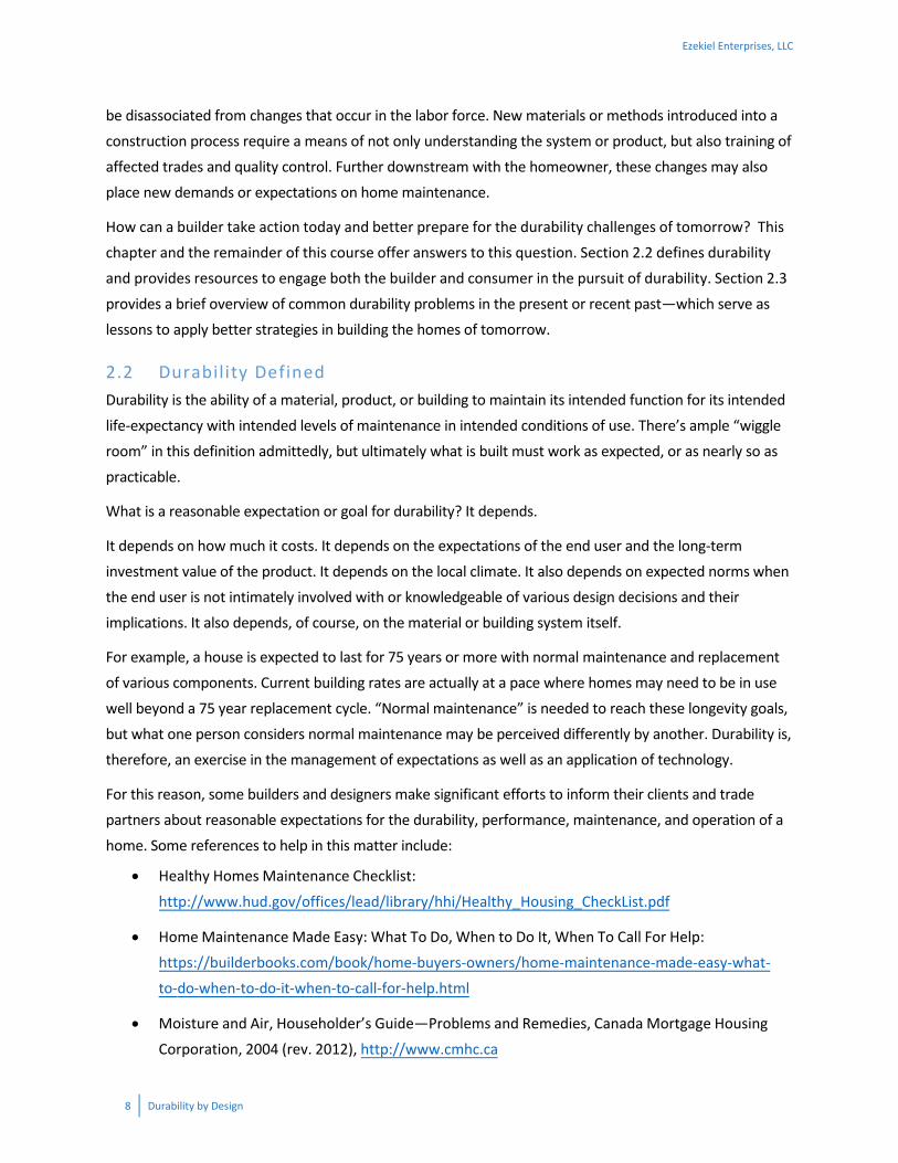
For enhanced protection against the formation of ice dams, use Table 4–4 to determine roof vent area
ratios. The ventilation ratios in Table 4–4 are a function of the venting layout and ceiling (attic floor)
insulation levels. These recommendations should be employed in areas with a ground snow load greater than 30 pounds per square foot (psf) and strongly considered in other areas where below freezing winter
temperatures and roof snow accumulation are expected. The following additional practices also apply:
A balanced placement of high (outlet) and low (inlet) vents as shown in Figure 4–4 and Table 4–3
above;
Use of air barrier practices in the ceiling to prevent warm, moist indoor air leakage into the attic space (refer to Section 4.3.2);
Adequate insulation and sealing of ductwork and HVAC equipment located in the attic space; and
Venting of all exhaust fans to outdoors (not the attic or attic eave).
Where the roof ventilation recommendations in Table 4–4 exceed code-minimum roof ventilation requirements (have more net vent open area than is required with the result of the 1:300 calculation),
additional benefits will also be realized in the control of water vapor diffusion and condensation in a roof system. Also, use of ice dam flashing in accordance with Figure 4–7 is still strongly recommended as a
means of providing “back-up” protection.
Ezekiel Enterprises, LLC
36 Durability by Design
Table 4–4: Recommended Roof Ventilation Levels
to Prevent Chronic Ice Damsa (for climates with ground snow load ≥ 30 psf and other areas prone to ice dams)
R-value of Roof/Attic
Insulation
Vent Ratiob
Vertical Separation
of Inlet (Eave/Cornice) and
Outlet (Ridge or Gable) Vents
3 ft 6 ft 9 ft 12 ft
Vented Attic Roofs R 19 1:100 1:140 1:180 1:200 R 30 1:160 1:230 1:280 1:300 R 38 1:200 1:290 1:300 1:300 R 49 1:260 1:300 1:300 1:300
Vented Cathedral Roofs R 19 1:100 1:140 1:250 1:250 R 30 1:160 1:230 1:250 1:250 R 38 1:200 1:250 1:250 1:250 R 49 1:250 1:250 1:250 1:250
Minimum Vent Depth for Air Passage in Cathedral Roofs
Roof Pitch Vent Depthc
3:12 to 5:12 2”
> 5:12 1 ½” Source: Crandell, J.H., “Ice Dams, Traditional and Improved Practices for Roof Ventilation and Prevention of Ice Dams,” Disaster Safety Review. Institute for Business and Home Safety, Tampa FL, 2004 Table Notes:
a. This table applies to roofs with a pitch of at least 3:12, an R-value of at least R 19, and a distance between inlets and outlets of no more than 40’.
b. Values are given as a minimum ratio of total open or unobstructed area of inlet and outlet vents (also known as “net free area”) to total horizontal projected area of the ventilated space (ceiling area). Inlet and outlet areas shall be balanced to the maximum extent practicable. For example on a simple gable roof, one-half of the calculated vent area shall be at the ridge and one-fourth at each of the two eaves.
c. Minimum vent pathway depth shall be maintained for entire ventilation air flow path from eaves to ridge or gable vents.
Ezekiel Enterprises, LLC

Durability by Design 37
Figure 4–7: Eave Ice Dam Flashing
4.2.6 Properly Size Roof Drainage (Gutters and Downspouts) Properly designed roof gutters reduce the amount and frequency of roof run-off water that wets the
above-grade walls or the foundation. A list of recommendations and a simplified design approach are presented below to help in the proper use of gutters. Further, an example problem is provided to illustrate
the simplified design approach.
Ensure that gutters have a slight downward slope toward downspouts.
Downspouts that discharge directly to the ground surface should do so at least 2’ outward from the building. Splash blocks or plastic corrugated pipe are recommended to prevent erosion and to give further extension of discharge water away from the foundation, particularly for downspouts
located at inside corners of building, if poor (such as expansive clay) soil conditions may exist, or where the ground surface slope away from the foundation is minimal.
Ezekiel Enterprises, LLC

38 Durability by Design
Where foundation backfill grade does not provide positive drainage away from the foundation, it should be corrected rather than simply relying on extension of downspout discharge. Should
gutters become clogged causing water to spill over, the surface grade away from the foundation will be the only means of preventing potential water intrusion or damage to foundation walls.
Downspouts that discharge water below grade should do so into nonperforated corrugated or smooth plastic pipe. The pipe should be run underground to a suitable outfall. Do not connect the
gutter drain pipe to the foundation drainage system; this practice will soak the foundation.
If local storm water management regulations require roof water infiltration on-site, do so at a maximum practicable distance from the building foundation; minimum separation distances
required by local storm-water regulations may not be adequate.
Gutters and downspouts should be resistant to corrosion and abrasion from flowing water;
material choices include aluminum (most popular), vinyl or plastic, copper, and coated metal (baked enamel or galvanized).
Use a gutter splash shield at inside corners (i.e., valleys) where fast moving water in a roof valley may “overshoot” the gutter.
Gutters, downspouts, and splash blocks must be cleaned and properly maintained by the
homeowner; where significant sources of roof and gutter debris exist (e.g., trees) a high-quality gutter guard system may be helpful in reducing the frequency of unclogging gutters.
A typical gutter installation uses a 5” deep K-style gutter with 2” by 3” downspouts at one or both terminal ends of gutters. While this “field practice” may be adequate for many homes in typical climate conditions,
the following simplified design approach is useful to determine situations where such designs may be inadequate.
Only two steps are required to properly design a steep-slope roof drainage system using standard
guttering products. Of course, this design method (drawn mostly from a 1999 industry reference15) assumes gutters are properly installed for positive drainage and that gutters are regularly cleaned to
maintain a “clog-free” condition.
Step 1: Determine Design Rainfall Intensity
The design rainfall intensity for roof drainage design is sometimes based on a 10-year return period and 5-minute duration (Figure 4–8). However, other design return periods and durations may be used effectively
or required by code (e.g., commercial building roof drainage). Conversion factors for other acceptable
15 “All About Gutters” by Andy Engel. Fine Homebuilding Magazine, August/September 1999. www.finehomebuilding.com
Ezekiel Enterprises, LLC

Durability by Design 39
design conditions are included in Figure 4–8. A standardized design criterion in U.S. model building codes for homes does not exist, so practical experience and judgment are important.
Figure 4–8: Rainfall Intensity Map of the United States
Step 2: Determine Roof Drainage System Spacing and Layout
Based on a selected gutter size and type as well as the design rainfall intensity from Step 1, determine the maximum allowable plan (horizontal) area of the roof that the gutter can adequately serve from Table 4–5,
including any adjustment required by the table notes. Based on this area and the roof geometry, downspout spacing and locations can be determined as shown in the example below. With use of the
suggested minimum downspout sizes in Table 4–5, the gutter size will control the spacing of downspouts. It is also generally recommended that downspouts should serve no more than 50’ of gutter length.
Ezekiel Enterprises, LLC

40 Durability by Design
Table 4–5: Maximum Allowable Tributary (Roof Slope ≤ 5:12)
Roof Plan Area (ft2)
Gutter
Design Rainfall Intensity (in/hr) Suggested
Minimum
Size and Type 3 4 5 6 7 8 9 10 Downspout
Size
5” ½-round 775 581 465 387 332 291 258 232 3” dia.
6” ½-round 1272 954 763 636 545 477 424 382 3” or 4” dia.
4” K-style 763 572 458 382 327 286 254 229 2”x3”
5” K-style 1399 1050 840 700 600 525 466 420 2”x3” or 3”x4”
6” K-style 2279 1709 1367 1139 977 854 760 684 3”x4”
Table Notes:
a. The tributary area served by gutter is defined by L x W. L is the length of the gutter to both sides of a downspout measured to termination of the gutter or to the high-point (drainage divide) between downspouts. W is the plan (horizontal) distance from the eave to the ridge of the roof area served.
b. The values in the table assume gutters with a minimum slope to prevent ponding and reverse flow. For gutters sloped at 1/16” per foot or greater, the table values may be multiplied by 1.1.
c. Allowable tributary roof plan areas (drainage areas) in the table are intended for roof slopes ≤ 5:12. For steeper roof pitches, multiply the tabulated areas by 0.85.
Example: Sizing roof gutters and downspouts in two steps
For the house located in Savannah, GA, as shown in Figure 4–9, the following example is provided to illustrate this best practice:
Figure 4–9: Gutter Design Example
Ezekiel Enterprises, LLC

Durability by Design 41
Step 1: Determine Design Rainfall Intensity
From Figure 4–8, a design rainfall intensity of 7 in/hr is determined for the site.
Step 2: Determine Roof Drainage System Spacing and Layout
A 5” K-style gutter is selected from Table 4–5 with a maximum allowable roof tributary plan area of 600 ft2. Because the roof slope is 6:12, the allowable tributary roof area is 0.85 x 600 ft2 = 510 ft2. The actual
horizontal (plan) roof area for the side shown is (14’x34’) + (14’x12’) = 644 ft2.
The number of downspouts required is 644 ft2 / 510 ft2 = 1.3. The number of downspouts should always be
rounded up, so two downspouts should be used, one at each end of the L-shaped gutter layout. The downspout size may be 2”x3” or 3”x4” as suggested in Table 4–5. Use of the larger size downspout, if
architecturally acceptable, may help reduce the potential for clogging from debris.
4.2.7 Specify a Climate-Appropriate Exterior Wall Covering Method Exterior wall covering materials and methods may look the same on the outside, but they may not perform the same even though they may be considered equivalent from a building code perspective. Exterior wall
covering assemblies can include features behind the siding that either improve or diminish a wall’s ability to protect a building from rainwater intrusion and moisture accumulation. The importance of this
consideration varies depending on climate. For example, some regions of the U.S. experience as much as 40”/year of rainfall impinging on vertical surfaces such as walls of buildings! Thus, it is appropriate to
consider that walls should perform like a vertical roof surface in deflecting and draining as much as 20 gallons per square foot per year of rainwater away from a building.
This section presents a simple procedure for selecting a durable and climate-appropriate method for
constructing an exterior wall covering assembly—something that U.S. building codes do not address—to
ensure risk-consistent performance in all climate conditions. Other important considerations include the
proper use and integration of flashing methods (Section 4.2.8) with a variety of water-resistive barrier (WRB) options as addressed in the text box on page 46. Proper specification of wind-driven rain resistant
window and door products is also important; this topic is addressed in Chapter 8 as it is especially important in areas subject to natural hazards such as tropical storms and hurricanes, although severe
thunderstorms can also cause similar conditions but with a much shorter duration.
There are essentially four methods for constructing a weather-resistant exterior wall envelope as
illustrated and described in Table 4–6. Each of these methods of construction provides different levels for managing or resisting rainwater by relying, to differing degrees, on one or more of the following three
principles:
Ezekiel Enterprises, LLC

42 Durability by Design
Deflection—Use of cladding to deflect water away from protected building components including the underlying water-resistive barrier layer.
Drainage—Use of a water-resistive barrier (WRB) integrated with other wall components and flashing to create a continuous drainage plane that directs water that leaks behind the cladding
(not deflected by the cladding surface) to drain downward and out of the assembly.
Drying—Use of a vented air-space behind siding to promote evaporation of water that is not
immediately drained or which is absorbed.
A fourth principle that always applies is related to the durability of the materials used for the various
components of an exterior wall covering assembly as well as the protected structural material within the wall. Specification of building materials that are tolerant of moisture and resistant to degradation (rot or
corrosion) will lessen the consequences of any moisture that defies the first three principles. Differences in the application of these principles are largely responsible for differences in the performance and durability
of exterior walls. Other determining factors include severity of wind-driven rain climate, roof overhang shielding of the wall, and site wind exposure—all of which are addressed in this section.
Ezekiel Enterprises, LLC

Durability by Design 43
Table 4–6: Exterior Wall Covering Assembly Methods
Drained Cavity Method—The drained cavity method relies on deflection, drainage, and drying to protect the wall from moisture damage. There are many possible variations. In general, a cavity exists to separate the cladding material from the surface of the underlying water-resistive barrier. The depth of the cavity, however, may vary. For example, vinyl siding may be placed directly on the WRB layer and still provide a cavity only restricted at points of contact (e.g., nail flanges). A minimum cavity depth of 3/8”is sometimes recommended, but often a depth of ¾” or 1 ½” is used based on the standard thickness of wood furring materials. Drained cavities increase the life of exterior finishes on wood surfaces and promote drying of wall assemblies after wetting episodes. For anchored masonry (brick) veneer, a 1” cavity depth is recommended to allow space for brick placement and mortar excesses. The drained cavity approach also can be applied to Portland cement stucco with use of a drainage mat or other appropriate means of creating a drainage cavity.
Face-sealed Method—This method relies exclusively on the ability of the outer surface of the wall and sealed joints around penetrations to deflect water and prevent it from penetrating the wall surface. If a defect in the wall surface or joint detailing (e.g., caulk) exists or occurs over time, then water will penetrate and potentially accumulate in the wall, causing damage to any moisture-sensitive materials within the assembly. One example of this type of system is known as conventional or barrier EIFS (exterior insulation finish system). However, current model building codes only allow the use of drainable EIFS (i.e., drained cavity) on residential wood-frame construction.
Ezekiel Enterprises, LLC

44 Durability by Design
Concealed Barrier Method—The concealed barrier method relies on porous cladding material adhered to or placed directly on an internal (concealed) water barrier or drainage plane. A common example is conventional stucco applied on two layers of Grade D building paper attached to a wood-frame wall. This method also relies primarily on deflection of rainwater (like the face-sealed system) but also has limited capability to absorb moisture to later dry and to drain moisture through weeps (e.g., weep screed) at the base of the wall. However, there is no open drainage pathway to allow water to freely drain from the concealed moisture barrier. Also, if moisture is stored in the cladding from a recent rain event and the rain event is followed by sun exposure, the effect is to drive water vapor into the wall assembly, especially when the wall design approach uses a vapor permeable WRB material.
Rainscreen Method—A rainscreen is similar to the drained cavity method with some added features that reduce air-pressure differential across the cladding system during wind-driven rain events; thus, water penetration through the cladding layer into the drainage cavity is further limited. At a minimum, this approach involves use of a rigid air barrier layer behind the cladding that is able to resist design wind pressures. Thus, wind pressure across the siding (which is vented or air-permeable and not air-tight) is reduced and is less likely to result in water being driven through the siding. Also, the cavity between the cladding and water/air barrier must be compartmentalized by use of air-tight blocking or furring at corners of the building (as a minimum practice) and sometimes more frequently for large facades with varying wind pressure regions. This feature prevents pressure differences on different surfaces of the building from “communicating” through a continuous cavity behind the cladding, which can cause unintended pressure differences across the cladding that drive rainwater through the cladding into the drainage cavity. Although the rainscreen method offers improved performance, the drained cavity method is usually considered a more practical alternative for typical homebuilding applications.
Ezekiel Enterprises, LLC

Durability by Design 45
Integrated Design and Construction: Water-resistive Barriers
Cladding provides a primary surface for deflection and drainage of moisture. But, some amount of water still
leaks behind essentially all claddings for various reasons. Therefore, a water-resistive barrier (WRB) provides
a secondary (and final) drainage plane. It is intended to create a continuous water-resistive layer that drains
water out from behind the cladding and prevents it from reaching sensitive materials deeper within the wall
(e.g., wood sheathing and framing).
Common WRB materials include various types of synthetic building wraps, 15# tarred felt, grade D building
paper, certain insulating sheathing products, certain proprietary structural sheathing products, adhered
membranes, and spray-applied coatings. The application of these materials must comply with the building
code, follow the manufacturer’s installation instructions, and be properly integrated with approved flashing
or sealing methods at penetrations and joints.
Not all water-resistive barrier materials and assemblies are equal in performance, nor are they all required
to meet a specific or consistent level of performance in a realistic water penetration assembly test, if
required at all for some WRB materials. Therefore, it is recommended that WRB assembly test data be
requested of the WRB manufacturer and, if available with acceptable results, follow the detailing
requirements used in the test.
Various WRB materials have different water vapor permeance (flow of moisture through a material)
properties. Depending on climate and the degree of vapor permeability or impermeability, integration with
the design and specification of other wall components for water vapor control may affect sheathing
material selection, wall insulation amounts and locations, and optimal interior vapor retarder properties
(refer to Section 4.3.3).
The design process below can be used to assess and specify an appropriate method of construction for an exterior wall covering assembly (see Table 4–6) based on wind-driven rain climate, roof overhang
protection, and wind exposure—the key factors governing the severity of rainwater loads experienced by walls.
Step 1: Assess Site Climate Condition
Climatic conditions are categorized on the basis of the potential for wetting of walls, especially wetting
from wind-driven rain. The exposure categories are:
Severe—climates that cause frequent wetting due to wind-driven rain, such as coastal climates
and areas prone to frequent thunderstorm events.
Moderate—climates that cause periodic exposure to wind-driven rain.
Low—climates that are relatively dry with little rainfall or wind-driven rain.
The above classifications are intentionally subjective, as there are no clearly defined criteria in the United States for assessing wind-driven rain and its effects on building wall systems. However, a wind-driven rain
Ezekiel Enterprises, LLC

46 Durability by Design
map is provided in Figure 4–10 as a means of classifying the severity of a local climate based on the above categories.
Figure 4–10: Wind-driven Rain Map of the United States
(Source: Underwood, S.J., A Multi-scale Climatology of Wind-driven Rain for the Contiguous United States 1971-1995, PhD Dissertation, University of Georgia, Athens, GA, 1999)
Step 2: Assess Building Exposure
The terrain surrounding a building impacts its exposure to wind-driven rain. The ratio of roof overhang width to the height of the protected wall below also alters the exposure of a given building wall to weather
and wind-driven rain. Wide roof overhangs relative to wall height effectively reduce the exposure. Similarly, increased shielding of the site against wind tends to reduce the effects of climate.
Table 4–7 may be used to determine a building’s exposure level, based on the climate condition determined in Step 1, the roof overhang ratio, and the wind exposure. The exposure level then leads to a
basis for selecting an appropriate exterior wall covering assembly method in Step 3. The exposure levels in Table 4–7 can also be used on a smaller scale to get a sense of the exposure for particular faces of a
building or even for specific envelope elements like a window. Understanding the exposure in this manner
Ezekiel Enterprises, LLC
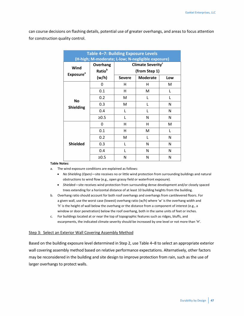
Durability by Design 47
can course decisions on flashing details, potential use of greater overhangs, and areas to focus attention for construction quality control.
Table 4–7: Building Exposure Levels (H-high; M-moderate; L-low; N-negligible exposure)
Wind
Exposurea
Overhang
Ratiob
(w/h)
Climate Severityc
(from Step 1) Severe Moderate Low
No
Shielding
0 H H M 0.1 H M L 0.2 M L L 0.3 M L N 0.4 L L N
≥0.5 L N N
Shielded
0 H H M 0.1 H M L 0.2 M L N 0.3 L N N 0.4 L N N
≥0.5 N N N Table Notes:
a. The wind exposure conditions are explained as follows: No Shielding (Open)—site receives no or little wind protection from surrounding buildings and natural
obstructions to wind flow (e.g., open grassy field or waterfront exposure). Shielded—site receives wind protection from surrounding dense development and/or closely spaced
trees extending for a horizontal distance of at least 10 building heights from the building.b. Overhang ratio should account for both roof overhangs and overhangs from cantilevered floors. For
a given wall, use the worst case (lowest) overhang ratio (w/h) where ‘w’ is the overhang width and ‘h’ is the height of wall below the overhang or the distance from a component of interest (e.g., awindow or door penetration) below the roof overhang, both in the same units of feet or inches.
c. For buildings located at or near the top of topographic features such as ridges, bluffs, and escarpments, the indicated climate severity should be increased by one level or not more than ‘H’.
Step 3: Select an Exterior Wall Covering Assembly Method
Based on the building exposure level determined in Step 2, use Table 4–8 to select an appropriate exterior
wall covering assembly method based on relative performance expectations. Alternatively, other factors may be reconsidered in the building and site design to improve protection from rain, such as the use of
larger overhangs to protect walls.
Ezekiel Enterprises, LLC

48 Durability by Design
Table 4–8: Relative Performance of Weather-Resistant Exterior Wall Methods a
Exposure Level
(from Table 4–7)
Face-sealed
Concealed Barrier
Drained Cavity
Basic Rainscreen
High (H) NR NR Fair Good Moderate (M) NR Fair Good Good
Low (L) Fair Good Good Good Negligible (N) Good Good Good Good
Table Note:
a. The ratings used to describe relative performance of the weather-resistant exterior wall systems are explained as follows: Good—the system is likely to meet or exceed acceptable performance expectations and has a low
risk of failure during the likely service life with a reasonable level of installation quality and maintenance.
Fair—the system is considered adequate, but may require careful attention to detailing, installation quality, and maintenance. The wall has a tolerable risk of failure during the likely service life.
NR—the system is not recommended for use on wood-frame home construction.
Solid or mass walls, such as masonry and concrete wall systems without a separate exterior cladding, are
not addressed in Table 4-6. These walls rely on deflection of rain as well as the ability to absorb moisture in
a sufficiently thick and durable wall system. However, even these “mass” walls can become overwhelmed
with moisture intake during extreme wind-driven rain episodes (e.g., hurricanes and tropical storms).
Water-repellent surface treatments or coatings like latex paint may be applied to these walls to improve
rain deflection and minimize absorption of moisture; however, such coatings should be semi-permeable to
allow for drying towards the outside. Various water-repellant treatments are available for concrete and
masonry, but they vary in cost, performance, and effective service life. Limited research indicates that
polysiloxane-blended water repellents may provide the best water repellency and durability.
Performance Evaluation of Water Repellents for Above-Grade Masonry, Research Highlights, Technical
Series 00-118, Canada Mortgage and Housing Corporation, Ottawa Canada, www.cmhc-schl.gc.ca/Research.
4.2.8 Flashing Matters: Do it Right! Water leaks in walls and roofs are commonly associated with flashing and detailing problems at penetrations and interfaces between wall and roof components. Despite the importance of flashing to the
durability of buildings, building codes provide little practical guidance or defer to “manufacturer installation instructions” which may be incomplete or limiting in the choice of materials and methods used to construct a wall.
This section focuses on key flashing concepts to provide a foundation for appropriate practices that can be extended to a variety of applications. In addition, typical building department inspections often do not
address flashing adequately because it is usually concealed once exterior finishes are installed. It is
Ezekiel Enterprises, LLC

Durability by Design 49
imperative that designers and builders consider this issue as a key element of construction plan detailing, construction trade coordination, and field quality control. Do not depend on caulk where flashing is
feasible. Where caulking is unavoidable or necessary, refer to Section 4.2.9.
Flashing materials and methods generally fall into one of the following three categories:
Mechanical Flashing—Generally a rigid, preformed or formable, non-corrosive and water-resistant material (e.g., aluminum, copper, plastic, etc.) shaped to direct water away from joints or around
components, mechanically fastened to a suitable substrate, and installed in an overlapping fashion to shed liquid water and prevent gravity-driven intrusion. Laps should be of a sufficient length to
prevent liquid water intrusion due to capillary action or pressure differential. Mechanical flashings include preformed flashing components such as window and door pan flashings.
Self-Adhering Flashing—Flexible, water-resistant facing materials coated completely or partially on at least one side with an adhesive material and which do not depend on mechanical fasteners
for permanent attachment; also known as flashing tape. They are used to bridge gaps and joints between components such as window flanges, mechanical flashing, water-resistive barriers, and
other components to provide a water-tight and durable seal such that liquid water is unable to penetrate by gravity, capillary action, or air pressure differential.
Liquid-Applied Flashing—A type of flashing material that is a fluid or paste at the time of
application and is applied by trowel, roller, spray, or other suitable method to provide a durable water-resistant coating or seal over compatible substrates and joints or interfaces between
materials to prevent liquid water intrusion.
The above flashing methods may be used individually or combined together for a variety of joint and
interface details between various types of WRB materials and wall or roof components. In each application, installation and flashing details required by the WRB, flashing, or component (e.g., window or
door) manufacturer should be consulted and component compatibility verified. In many cases, approved applications must use a very specific set of materials because they act as a system.
The remainder of this section provides guidance and flashing concepts for a sample of applications with common materials. Regardless of the flashing method applied, the first step is to identify all the areas
where flashing is needed. For example, refer to the house shown in Figure 4–11. As noted in Chapter 2 and shown in Figure 4–11, typical locations where flashing is very important (and often defective) include
window and door heads, and step/kick out flashing at roof-wall intersections. While all flashing is important, these locations seem to be two of the most problematic and consequential.
Ezekiel Enterprises, LLC

50 Durability by Design
Step flashing is illustrated in Figure 4–12. Step and kick out flashing should be used at roof-wall
intersections, with the flashing extending at least 4” up the wall surface above the roof deck and
integrated shingle-style with drainage plane above or sealed with self-adhering flashing tape approved
for the application.
Window flashing details should follow the window manufacturer’s installation instructions or provide an equivalent solution, as appropriate given the type of WRB approach being used. One example of window
flashing sequence is shown in Figure 4-13, for a wall assembly which includes exterior foam insulation (which is becoming increasingly common based on energy codes). While the figure details the steps in this
process, the key concept is integrating the WRB layer and window units with a compatible and approved self-adhering flashing tape to drain bulk water away from the window opening. This practice as well as
other flashing practices should employ a drainage pan at the window sill to remove water that may penetrate the window unit itself (see Step 1 in Figure 4–13).
Figure 4–14 illustrates a deck ledger flashing detail. This assembly often is created after the initial construction of a home, and is particularly important because it carries structural safety implications
directly related to the long-term ability of the flashing to manage water. The flashing and fasteners used in treated wood materials must be compatible with wood preservative treatments for durable moisture protection (e.g., avoid aluminum or electroplate galvanized steel—see Section 8.2.2).
For additional guidance on flashing methods and details, several additional resources with more extensive flashing details are noted in Section 4.4. Key flashing references listed in this section include Keeping Walls
Dry (CMHC), Weather Resistive Barriers (U.S. DOE), and Guidance on Taped Insulating Sheathing Drainage
Planes (U.S. DOE Building America program). Increasingly, useful flashing installation videos are easily
found online as well.
Ezekiel Enterprises, LLC

Durability by Design 51
Kick Out Flashing
Opening head/jamb/sill flashing
Horizontal change of materials flashing
Roof/wall junctions step flashing
Chimney flashing & counter-flashing
Figure 4–11: Typical Locations Where Flashing Details Are Required
Figure 4–12: Step and Kick Out Flashing
Ezekiel Enterprises, LLC

52 Durability by Design
Figure 4–13: Window Flashing Sequence on a Wall With Exterior Foam Insulation
Ezekiel Enterprises, LLC

Durability by Design 53
Figure 4–14: Deck Ledger Flashing Detail
4.2.9 Properly Use Caulks and Sealants In the construction of exterior wall and roof coverings, there will be joints and seams that require or benefit from the appropriate specification, use, and maintenance of caulks or sealants. When possible, use
flashing instead of caulking and use caulking only as a supplement to flashing that is properly integrated with the WRB installation (refer to Section 4.2.7 and 4.2.8). Whether caulking is used to cover up poor
detailing or required as a necessary component in certain details, it can have a significant impact from a durability and liability standpoint.16
In the absence of guidelines for a specific application, the generic caulk recommendations in Table 4–9 should be considered and the selected caulk manufacturer’s instructions carefully followed. Poor
performing caulks or poorly installed caulking can fail in less than a year, creating an unreasonable
expectation for maintenance and greater likelihood of moisture problems (see text box). A high quality caulk installation requires skill and appropriate ambient temperature, dry and clean surfaces, and an
16 O’Connor, T.F., “The One Percent of Cost That Can Become 90 Percent of Trouble,” ASTM Standardization News, American Society of Testing and Materials, West Conshohocken, PA, June 2003.
Ezekiel Enterprises, LLC

54 Durability by Design
adequate joint gap to allow the caulk to act elastically without pulling loose. Too thick of a bead restricts the flexibility of the caulk, which can result in failure of the joint. Instead, the use of backer rod really
matters and can result in a better formed, more flexible bead that will adhere far better. For additional guidance, refer to appropriate resources in Section 4.4, such as ASTM C1193.
Table 4–9: Caulk Selection Aida
Caulk Type Lifeb (yrs.) Relative
Performance Comments
Oil-base 1–5 NR Not recommended for durable exterior
waterproof sealing
Latex (acrylic) 2–7 NR Not recommended for durable exterior
waterproof sealing Butyls 5–10 Average No primer required
Acrylic (solvent release)
5–20 Average No primer required
Polysulfide 10–20 High Primer may be required for some surfaces Silicone 10–25 High Primer may be required for some surfaces
Polyurethane 10–20 High Primer may be required for some surfaces
NR = not recommended
Sources: CSA Standard A4440.4-2007, Annex C, Sealant Selection; Structures and Environmental Handbook, Eleventh Edition (Midwest Plan Service, 1983); Forgues, Y.E., “Properly Sealed Construction Joints,” Construction Practice, Institute for Research in Construction, National Research Council Canada, http://irc.nrc-cnrc.gc.ca
Table Notes:
a. This table is intended as a general guide. Manufacturer’s sealant application and installation recommendations should be consulted.
b. Life expectancy estimates are based on ideal conditions with high quality installation.
“Joints sealed with an elastomeric sealant usually fail from a combination of factors that can be summed
up in six words—a lack of attention to detail. Too often, since the sealants are a small percentage of the
work, they are perfunctorily specified, easily substituted, and haphazardly applied. Yet successful joints
require meticulous design, precise sealant selection, and painstaking application.”
Why Sealant Joints Fail, Karen Warseck, AIA.
Ezekiel Enterprises, LLC

Durability by Design 55
4.3 Recommended Practices for Water Vapor Management
4.3.1 General With improved insulation requirements in modern energy codes, “green” codes, and above-code energy
efficiency programs, envelope assemblies allow less thermal energy transfer resulting in energy savings. This benefit comes with a climate-dependent consequence: colder surface temperatures on materials to
the interior side of an air-conditioned building in the summer, or exterior side in the winter. When these cooled surfaces are exposed to moisture-laden air leaks (from the exterior in the summer or from the
interior in the winter) or excessive vapor diffusion through the assembly, they become more prone to condensation and moisture accumulation. Fortunately, this problem has durable solutions as discussed in
this section.
An effective air barrier installation (Section 4.3.2) and vapor diffusion control strategy (Section 4.3.3) have
become increasingly important to the durability of modern energy efficient homes. Furthermore, new homes usually have a significant quantity of “built-in” or initial moisture embodied in materials like concrete and lumber which will create additional water vapor loads during the first year or so of a
building’s operation as those products dry. Thus, reduction of “built-in” construction moisture has also increased in importance (Section 4.3.4).
Ezekiel Enterprises, LLC

56 Durability by Design
Integrated Design and Construction: Water Vapor Control
Uncontrolled and elevated indoor humidity levels have been identified as a key contributor where water
vapor problems occur. Any attempt to control water vapor should start with attention to controlling indoor
relative humidity levels and air-pressure differences across the building envelope. This integrated design
topic is addressed in Chapter 5—HVAC and Plumbing. Appropriate mechanical system design (equipment
sizing, ventilation, humidity control, etc.) provides a crucial “safety factor” against high indoor relative levels
which can overwhelm reasonable attempts to cure the problem by use of air barriers and vapor retarders.
As with the design of a structural system, the moisture control system of a home is only as strong as its
weakest link.
Window condensation is often a sign of elevated indoor RH levels.
4.3.2 Leverage Air Barriers to Manage Air Leakage and Moisture Air barriers are often considered purely as an efficiency measure to control energy losses associated
with air-leakage to or from the building’s conditioned spaces. In reality, air barriers serve energy efficiency and moisture control functions. In fact, movement of moisture-laden air into well insulated
building assemblies can cause much more condensation or moisture accumulation to occur within the assembly than might otherwise result from water vapor diffusion alone. Controlling water vapor
diffusion with a vapor retarder is practically futile without also controlling air leakage with an air barrier. Thus, air barriers deserve special attention in design and construction from a moisture durability
perspective.
Going beyond code minimum practices can provide significant benefits in energy conservation and
moisture control. For example, Table 4–10 provides important locations for air barriers intended to manage moisture and uphold the performance of the insulation based on the EPA’s ENERGY STAR
Homes program. These may exceed minimum code requirements for only a single air barrier location on the interior or exterior side of an assembly. For example, in Climate Zones 4–8 an air barrier is required on the interior and exterior side of wall insulation for an exterior wall assembly. Similarly, air barriers are
required at interior horizontal surfaces and exterior perimeter vertical surfaces of insulation for floors in all climate zones. Air impermeable insulation materials such as closed-cell spray foam can serve the
Ezekiel Enterprises, LLC

Durability by Design 57
purpose of insulation as well as air barrier, and may be considered as an alternative to the recommendations in Table 4–10 which presumes the use of air-permeable cavity insulation.
Table 4–10: Summary of EPA ENERGY STAR Air Barrier Requirements Climate Zone (Figure 4–15)
Interior Air Barriera Exterior Air Barriera
WALLS
1–3 Not required Required at exterior vertical surface of wall insulation 4–8
Required at interior vertical surface of wall insulationb
CEILINGS
1–3 Required at interior or exterior horizontal surface of insulationc
4–8 Required at interior horizontal surface of insulationc Not required
FLOORS
1–8 Required at interior horizontal surface of insulation
Required at exterior (perimeter) vertical surface of insulation
Table Notes:
a. Air barriers must be continuous and fully aligned with insulation. b. Also includes floor cavities which are part of the wall’s thermal plane, like a rim joist between upper and
lower story walls. c. Also provide an air barrier at the exterior vertical surface of insulation near eaves using a wind baffle or
equivalent.
Figure 4–15: The International Energy Conservation Code Climate Zone Map
Source: U.S. Department of Energy
Ezekiel Enterprises, LLC
58 Durability by Design
Figure 4–16 shows one example of an air barrier installation on the interior side of an exterior wall and another on the exterior side. In both cases the air barrier is continuous with the ceiling at the roof level.
Where an interior and exterior air barrier is installed, both of these practices are used as a means for improved insulation performance (energy efficiency) and air leakage control (water vapor control and
energy efficiency).
A practical interior air barrier installation involves detailing the interior gypsum board finish as an air
barrier layer along with framing connections between walls. A typical exterior air barrier involves the use of a water-resistive barrier membrane (e.g., wrap) with taped joints and penetrations or an
approved exterior panel type material, also with taped or sealed joints and penetrations. The two methods shown in Figure 4–16 are common examples. Whichever interior and/or exterior air barrier
method and material is used must be coordinated with the vapor control strategy for the assembly
(Section 4.3.3) and the rainwater management approach for exterior air barrier applications
(Section 4.2).
Ezekiel Enterprises, LLC

Durability by Design 59
Figure 4–16: Examples of Exterior and Interior Continuous Air Barrier Strategies
Source: Air Leakage Guide, U.S. Department of Energy, Building Technologies Program. Original Images from Building Science Corporation’s “Air Barriers” publication (Research Report 0403, 2004).
While there are a variety of air barrier materials worth considering and integrating into the overall
moisture control strategy for a building envelope, these materials all must comply with building code and certain material or assembly testing requirements for air permeance. Of course, some materials like
wood structural panels, gypsum board, concrete, and sheet aluminum or polyethylene, have obvious air barrier material characteristics. Others may depend on characteristics that are not easily observed by
the naked eye. Thus, manufacturer data on air permeance (and also other properties such as vapor permeance) should be sought and used as a basis for design and material selection.
Ezekiel Enterprises, LLC

60 Durability by Design
It is always necessary to use air barrier materials in a way that creates a continuous air barrier layer to
prevent air leakage through a multitude of potential leakage points (Figure 4–17). Building codes and
good practice include requirements to seal all joints and penetrations for visual confirmation or,
alternatively, require air pressure testing of the building (e.g., “blower door” test) to verify performance
of the final air barrier installation. This course recommends use of a blower door test. It will measure
the air change per hour (ACH) of a building to ensure energy code compliance and is a useful
diagnostic and training tool (with the use of a smoke stick) to help locate and correct air leaks that
may otherwise go undetected and cause potential moisture durability problems within assemblies.
Figure 4–17: Air Leakage Points Requiring Special Attention for a Continuous Air Barrier Installation
Source: Air Leakage Guide, U.S. Department of Energy, Building Technologies Program.
Ezekiel Enterprises, LLC

Durability by Design 61
Integrated Design and Construction: Fuel-fired Heating Equipment and Air Barriers
What is the conflict between a gas furnace or water heater and an air barrier? One wants air and the other
holds it back. If an air-tight building is depressurized due to exhaust fan operations, wind, or the “stack
effect” in the winter, then back-drafting of combustion equipment is more likely to occur and introduce
combustion byproducts (e.g., water vapor and carbon monoxide) into the home. Because of these health
and safety concerns, sealed combustion equipment with power drafting is recommended in Chapter 5.
4.3.3 Water Vapor Diffusion Control: Do Your Homework…Before You Build Water vapor diffusion speaks to the movement of water in its gas or vapor form into and through materials. Thus, water vapor control involves selecting materials and assemblies with appropriate
properties to manage, not eliminate, the effects of water vapor.
The goals of water vapor control are:
To prevent excessive vapor movement into assemblies,
To allow vapor to move out, and
To control temperatures within the assembly to keep it in the vapor form (e.g., prevent
condensation). When organic materials like wood are exposed to excessive water vapor or condensation, they will increase in moisture content to a point where damage may occur.
Thus, water vapor control is a climate-dependent balancing act to control the accumulation of moisture to tolerable levels and ensure that the ability of an assembly to dry out exceeds its potential to get wet. In
other words, moisture that accumulates to tolerable levels due to diffusion in one season must dry out by diffusion in the next season to avoid a long term cycling of moisture that results in a gradual year-to-year
accumulation. In addition, to prevent mold growth moisture accumulation within organic materials (e.g., wood, paper-faced drywall) or high surface RH levels on these materials (e.g., greater than 80%) must be prevented from occurring over an extended period of time.
To the extent that diffusion drying (moisture removal) exceeds diffusion wetting (moisture accumulation) over the course of a year, an assembly is considered to be more or less able to tolerate unintentional and
uncertain amounts of moisture that may be introduced from other sources such as rainwater leaks (Section 4.2) or moisture-laden air leaks (Section 4.3.2). Building materials such as dimensional lumber,
which have the ability to “store” moderate amounts of water vapor, can also serve as a “buffer.” They can absorb moisture during seasons with greater levels, and then release it when conditions are more
conducive to drying. However, no reasonable approach to water vapor control is able to make up for leaks of rainwater or moist air due to poorly installed water-resistive barriers, flashing, and air barriers.
Therefore, the recommendations for water vapor control in this section are predicated on a quality
Ezekiel Enterprises, LLC
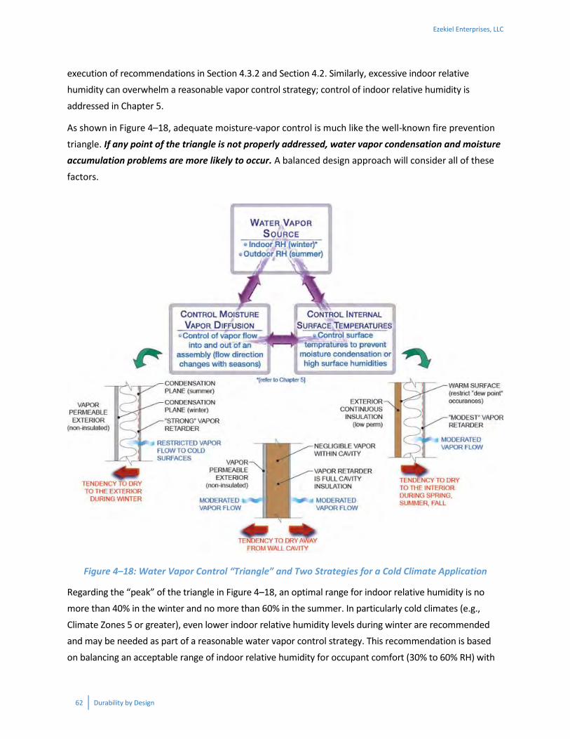
62 Durability by Design
execution of recommendations in Section 4.3.2 and Section 4.2. Similarly, excessive indoor relative humidity can overwhelm a reasonable vapor control strategy; control of indoor relative humidity is
addressed in Chapter 5.
As shown in Figure 4–18, adequate moisture-vapor control is much like the well-known fire prevention
triangle. If any point of the triangle is not properly addressed, water vapor condensation and moisture
accumulation problems are more likely to occur. A balanced design approach will consider all of these
factors.
Figure 4–18: Water Vapor Control “Triangle” and Two Strategies for a Cold Climate Application
Regarding the “peak” of the triangle in Figure 4–18, an optimal range for indoor relative humidity is no more than 40% in the winter and no more than 60% in the summer. In particularly cold climates (e.g.,
Climate Zones 5 or greater), even lower indoor relative humidity levels during winter are recommended and may be needed as part of a reasonable water vapor control strategy. This recommendation is based
on balancing an acceptable range of indoor relative humidity for occupant comfort (30% to 60% RH) with
Ezekiel Enterprises, LLC

Durability by Design 63
the need to protect the building envelope from excessive water vapor flows during the winter heating and summer cooling seasons. Controlling indoor relative humidity is addressed in Chapter 5. In addition,
construction moisture (Section 4.3.4) and foundation moisture (Chapter 3) can contribute significant amounts of water vapor to indoor air if not adequately addressed.
The base of the triangle in Figure 4–18 involves the control of water vapor diffusion and internal surface temperatures. These relate to design of the building envelope assembly and require an integrated
approach. There are three commonly accepted practices that, when done correctly, provide walls with
a greater tendency to remove moisture by diffusion rather than allowing moisture to accumulate via
moisture diffusion.
One method controls moisture condensation or accumulation by reducing the entry of water vapor into
the assembly (i.e., more emphasis is placed on vapor retarders). This strategy (Figure 4–18 lower left) also uses a vapor permeable wall exterior to allow outward drying during the winter. This assembly assumes
vapor permeable cavity insulation.
A second method (Figure 4–18 bottom center) incorporates air and vapor impermeable (low permeance)
insulation materials in the cavity to control vapor flow through the assembly while still allowing materials on each face to dry to the interior or exterior, respectively. Assemblies using this strategy include SIPs panels and wood-framed assemblies with the cavity filled with air and vapor impermeable spray foam
insulation.
A third method (Figure 4–18 lower right) uses exterior insulation to keep the temperature of the assembly
warmer. This temperature control approach prevents condensation from occurring on a surface within the assembly that might otherwise drop below the “dew point” temperature.17 This assembly assumes vapor
permeable cavity insulation.
Finally, “vapor open” walls that allow water vapor diffusion wetting and drying in both directions may also
be considered, but usually work best in dryer climates and those that are not very cold. Again, balance is the key.
The principles behind the vapor control approaches described above are incorporated into “three rules” for water vapor control:
17 The dew point temperature is most simply defined as the temperature at which dew (i.e., condensation) begins to form. For example, when air with a given water vapor content is exposed to a surface colder than the air, condensation will occur when the surface temperature is at the “dew point.” The more water vapor in the air, the more likely a surface will be cold enough to cause condensation to occur.
Ezekiel Enterprises, LLC

64 Durability by Design
1. Maintain the envelope assembly’s ability to dry in at least one direction by not installing low-
perm vapor retarders (e.g., vapor barrier) or other low-perm vapor retarding materials on
both sides of an assembly.
2. Do not put a low-perm vapor retarder (e.g., vapor barrier) or vapor retarding materials (e.g.,
vinyl wall paper) on the inside of an assembly in a hot/humid climate.
3. Depending on climate zone and insulation strategy, seek to optimize the assembly’s ability to
dry and limit the potential for wetting by vapor diffusion.
The first two rules are pretty straightforward, yet deserve mention because failures to follow these two
rules have resulted in significant moisture damage to buildings. The last rule, however, is a good bit trickier because it is a matter of optimization and there are many ways to achieve an optimal or at least
acceptable assembly (and also many more ways to achieve one that is not).
Tables 4–11 and 4–12 are offered as aids in applying the above three rules in most climate zones. Climate
Zone 8 (subarctic) is excluded from this document due to its limited application in the United States and, in such severe conditions, the reader is encouraged to use a specially designed solution that meets or
exceeds locally applicable code requirements. The provisions summarized in Tables 4–11 and 4–12 are based on a compilation of requirements in Part 9, Sections 9.25.4 and 9.25.5 of the 2010 National Building
Code of Canada, Section 702.7 of the 2015 International Residential Code, Section 1405 of the 2015
International Building Code, and various substantiating technical resources.18, 19, 20, 21, 22, 23, 24, 25, 26, 27 Also included are a few modifications intended to enhance performance, offer guidance, or draw attention to
considerations where the building code may be silent, incomplete or vague. However, it should be
18 Lstiburek, J. (2011). Building Science Digest 106, Understanding Vapor Barriers, rev. April 2011. www.buildingscience.com 19 Lstiburek, J. (2004). Research Report 410, Vapor Barriers and Wall Design, November 2004, www.buildingscience.com 20 Straube, J. (2012). High Performance Enclosures: Design Guide for Institutional, Commercial and Industrial Buildings in Cold Climates, Building Science Press, www.buildingscience.com 21 Straube, J. (2012). High Performance Enclosures: Design Guide for Institutional, Commercial and Industrial Buildings in Cold Climates, Building Science Press 22 Karagiozis, A, Lstiburek, J., Desjarlais, A. (2007). Scientific Analysis of Vapor Retarder Recommendations for Wall Systems Constructed in North America. ASHRAE, Buildings X. 23 Kumaran, M.K., and Haysom, J.C. (2000). Low-Permeance Materials in Building Envelopes, Construction Technology Update No. 41, National Research Council of Canada (revised March 2002) 24 Kumaran, M.K. and Haysom, J.C. (2001). Avoiding Condensation with low-permeance materials, NRCC-44704, National Research Council Canada, Institute for Research in Construction 25 Chown, G.A. and Mukhopadhyaya, P. (2005). NBC 9.25.1.2: The on-going development of building code requirements to address low air and vapour permeance materials, NRCC-47656, National Research Council Canada, Institute for Research in Construction 26 Brown, W.C., Roppel, P., and Lawton, M. (2007). Developing a Design Protocol for Low Air and Vapour Permeance Insulating Sheathing in Cold Climates, Buildings X, ASHRAE 27 NRC-Canada (1997). Air barrier Systems for Walls of Low-Rise Buildings: Performance and Assessment, ISBN 0-60-16862, NRCC 40635, National Research Council of Canada
Ezekiel Enterprises, LLC

Durability by Design 65
understood that these recommendations are based on various sources and assumptions, and do not preclude alternative solutions or exclusively define acceptable solutions. Therefore, the user is encouraged
to use good judgment, seek professional assistance, verify the suitability of these requirements, and confirm compliance with the locally applicable building code and energy code.
The application of Tables 4–11 and 4–12 requires an understanding of the following code definitions:
VAPOR RETARDER CLASS. A measure of the ability of material or an assembly to limit the
amount of water vapor that passes through that material or assembly. Vapor retarder class shall be defined using the desiccant (dry cup) method with Procedure A of ASTM E 96 as follows:
Class I: 0.1 perm or less (e.g., sheet polyethylene, unperforated aluminum foil)
Class II: 0.1 < perm ≤ 1.0 perm (e.g., kraft-faced fiberglass batts)
Class III: 1.0 < perm ≤ 10 perm (e.g., latex or enamel paint appropriately rated and installed)
VAPOR PERMEABLE. The property of having a water vapor permeance rating of 5 perms (2.9 x 10⁻¹⁰ kg/Pa · s · m2) or greater, where tested in accordance with the desiccant method using
Procedure A of ASTM E 96. For the purposes of this document, vapor permeability also is permitted to be assessed using the wet cup method (Procedure B) of ASTM E96.
The vapor permeance of specific vapor retarder materials should be verified by checking product-specific
test data in the process of applying the requirements of Tables 4–11 and 4–12. In addition, other wall material layers such as exterior sheathing material, building wrap, spray foam, and foam sheathing also
should be verified. While generic data is available from various sources, such as the ASHRAE Handbook of
Fundamentals, product-specific test data from the product manufacturer is usually the best source as
properties can vary significantly even among like products. It also is important to consider the product manufacturer’s design data and technical resources which may contain alternative solutions than those
included in Tables 4–11 and 4–12.
While the vapor retarder class as defined above is based on vapor flow under relatively dry conditions, it
also is important to know if the material’s properties change when tested under more humid conditions (i.e., perm rating per the wet cup or Method B of ASTM E 96). For example, uncoated wood sheathing
products may be rated as a Class II vapor retarder under the “dry cup” condition, but can become vapor permeable (> 5 perm) under the “wet cup” condition. Similarly, some common vapor retarders, such as
kraft paper, and other proprietary “smart vapor retarder” products, exhibit an ability to restrict vapor flow under low humidity conditions and permit vapor flow when drying conditions are needed. For example, the ASHRAE Handbook of Fundamentals reports that kraft paper has an ASTM E96 dry cup perm rating of
about 0.3 perms (Class II vapor retarder) yet also has an ASTM E96 wet cup perm rating of about 1.8 perms
Ezekiel Enterprises, LLC

66 Durability by Design
or greater (Class III vapor retarder)—a factor of 6 difference in vapor permeance due to difference in ambient air humidity. Thus, the selection of a smart vapor retarder can help optimize an envelope
assembly to resist wetting during one period of the year and yet also promote drying during another season.
Table 4–11: Water Vapor Control Methods and Requirements for Envelope Assembliesa
Climate Zone (Figure 4–15)
Vapor Retarder Class and Location Requirements
1–2 A Class I or II vapor retarder should not be applied on the interior face of the envelope assembly. Use of a Class III vapor retarder on the interior face is permitted.b
3 –7
Use one of the following methods depending on climate zone, insulation strategy, and vapor permeance of materials located on the exterior face of an envelope assembly:
A. Cavity Insulation Only (using air- or vapor permeable insulation): i. Use a Class I (CZ 5-7) or Class II (CZ 4-6) or Class III (CZ 3) vapor retarder on the interior side of the cavity insulation; it is recommended that vapor permeablec sheathing materials be used on the exterior side in CZ 5-7, or ii. Use a Class III vapor retarder on the interior side of the cavity in CZ 4-6 with vented claddingd and exterior sheathing as follows: wood structural panel (CZ 4-5), fiberboard (CZ 4-6), or gypsum (CZ 4-6).
B. Cavity Insulation + Continuous Insulation, or Spray Foame: Use a Class II or Class III vapor retarder on the interior face of the envelope assembly and meet or exceed the appropriate minimum insulation ratio in Table 4–12. Alternatively, use closed cell spray foam within the cavity in combination with or in lieu of exterior continuous insulation (refer to footnote c of Table 4–12).
8 (subarctic) Design Recommended Table Notes:
a. The water vapor control methods and requirements of this table are best used under the following conditions: i. Indoor relative humidity not exceeding 40% (CZ 3-4), 35% (CZ 5-6), or 30% (CZ 7) during the coldest months of
the winter heating season; lower indoor relative humidity will improve water vapor performance but may cause excessively dry conditions for human occupancy.
ii. Use of a continuous air barrier system as described in Section 4.3.2 and quality installation methods to minimize uncontrolled air leakage into and through the assembly.
iii. Use of a continuous water-resistive barrier system and flashing, together with a climate-appropriate exterior wall covering method as described in Sections 4.2.7 and 4.2.8, to minimize potential for rainwater intrusion.
iv. Wall framing and other materials, such as wet-blown insulation, are dried to 15% or lower moisture content prior to installation of an interior vapor retarder (where required) and interior finishes (Section 4.3.4).
b. A Class II vapor retarder that also qualifies as Class III using the wet cup method of ASTM E96 shall be permitted on the interior face (example: kraft-faced fiberglass batts).
c. Vapor permeability shall be permitted to be assessed using the wet cup method (Procedure B) of ASTM E96. Also, other common recommendations include use of a 5:1 (outside to inside) permeance ratio. For example, if a 0.1 perm (Class 1) vapor retarder is used on the inside then minimum 0.5 perm is required on the outside. Similarly, if a 1 perm vapor retarder is used on the inside, then a minimum 5 perm is required on the outside. However, it is not recommended to extend this permeance ratio rule to the extreme of 0.05 perm inside (e.g., polyethylene sheet) with minimum 0.25 perm outside, because such a wall becomes questionable in its drying potential should it become wet due to causes other than vapor diffusion.
Ezekiel Enterprises, LLC

Durability by Design 67
d. For the purposes of this table, vented cladding includes (1) vinyl lap or horizontal aluminum siding, (2) brick veneer with a clear airspace, or (3) other approved vented claddings with equivalent vent area.
e. These provisions assume vapor impermeable continuous insulation, and thus also apply to continuous insulation which is more vapor permeable. In Climate Zones 5–7, where the exterior continuous insulation is a Class II vapor retarder material or has greater vapor permeance, use of a Class I interior vapor retarder on the interior may provide improved performance or allow reduction of minimum insulation ratios recommended in Table 4–12.
Table 4–12: Minimum Insulation Ratios for Use With Class II and III Interior Vapor Retarders on Walls with Exterior Continuous Insulationa
Climate Zone (Figure 4–15)
Maximum Heating Degree
Days (HDD65oF)
Class II Interior Vapor Retarderb
Class III Interior Vapor Retarderb, c
Min. Re/Ri
d Examplese (Ri + Re,ci)
Min. Re/Ri
d Examplese (Ri + Re,ci)
1–3 < 5,400 No limit No Limit No Limit No Limit
4 5,400 0.2 R13+R2.6ci R20+R4ci 0.2 R13+R2.6ci
R20+R4ci
5 (cold) 7,200 0.2 R13+R2.6ci R20+R4ci 0.35 R13+R4.6ci
R20+R7ci
6 (cold) 9,000 0.25 R13+R3.3ci R20+R5ci 0.5 R13+R6.5ci
R20+R10ci
7 (very cold) 12,600 0.35 R13+R6.5ci R20+R7ci 0.7 R13+R9.1ci
R20+R14ci 8 (subarctic) >12,600 Design Recommended
Table Notes:
a. Refer to Note ‘a’ in Table 4–11 above for conditions of use. b. For the purpose of this table, a Class II vapor retarder includes kraft paper facer or other Class II vapor retarder materials
that also qualify as Class III using the wet cup method of ASTM E96. Also, refer to footnote ‘e’ of Table 4–11. Also, a Class I vapor retarder may be permissible for continuous insulation materials that are not vapor impermeable—refer to manufacturer data.
c. Spray foam with a maximum permeance of 1.5 perms at the installed thickness, applied to the interior cavity side of wood structural panels, fiberboard, insulating sheathing, or gypsum, is deemed to meet the continuous insulation requirement where the spray foam R-value meets or exceeds the specified continuous insulation R-value.
d. Re = exterior continuous insulation (ci) component R-value; Ri = cavity insulation component R-value. e. Example insulation solutions are shown for combinations of cavity insulation (first value) plus continuous insulation
(second value) that satisfy the required minimum insulation ratio. Other solutions of cavity insulation and continuous insulation, including continuous insulation only, with equal or greater insulation ratio are acceptable. Increasing the insulation ratio by increasing the continuous insulation R-value and/or decreasing the cavity insulation R-value will improve water vapor performance. These insulation ratios and their application address minimum requirements for water vapor control only; thermal performance for energy code compliance must be separately verified.
Example: Using insulation ratios to check energy code solutions and alternative wall
insulation strategies for adequate moisture durability Given: Assume the energy code requires R20+5 (2x6 wall with R20 cavity insulation and R5 continuous insulation).
Find: What is the maximum (coldest) permissible climate zone for this wall with a Class II or Class III
interior vapor retarder?
Ezekiel Enterprises, LLC

68 Durability by Design
Solution: First, determine the insulation ratio, Re/Ri = 5/20 = 0.25. In accordance with Table 4–12, the maximum/coldest climate zone is 6 with a Class II interior vapor retarder and Climate Zone 4 with a Class III
interior vapor retarder. While this example assembly may be permitted as a prescriptive solution in the energy code, the insulation ratio should be checked as demonstrated in this example. Consequently, the
insulation locations and amounts may need to be adjusted to achieve moisture control while also still complying with the required energy code thermal performance. Some creative options are discussed next.
For example, changing to a R13+R10ci insulation strategy using a 2x4 wall which is thermally equivalent will increase the insulation ratio to 10/13 = 0.77, providing much improved water vapor control or the
ability to tolerate higher indoor RH conditions.
Alternatively, closed-cell spray foam may be added to the cavity to achieve required thermal and
moisture control performance (e.g., see Note c in Table 4–12). This is often efficiently done using a “flash and batt” approach (which may also be combined with exterior continuous insulation) as a means
of economizing insulation cost while also creating an air barrier.
Example: Getting More Creative with Insulation Ratios
Given: Consider a wall assembly comprised of R15 high density batt insulation in a 2x4 wall, the use of
exterior continuous insulation, and R2 insulating (foam backed) vinyl siding.
Find: What would be the required R-value (and thickness) of the exterior continuous insulation to use
this assembly in Climate Zone 6 with a Class III interior vapor retarder (latex paint on drywall)?
Solution: In accordance with Table 4–12 a minimum Re/Ri ratio of 0.5 is required. Thus, the exterior
continuous insulation amount must be at least R15 x 0.5 = R7.5. Because the insulating siding provides at least R2 of this exterior continuous insulation, the insulated sheathing only needs to make up the
difference of 7.5R – R2 = R5.5.
Thus, the following insulated sheathing options are possible:
1.5” of EPS foam sheathing (R6),
1” of XPS (R5) plus an insulated vinyl siding of R2.5 instead of R2, or
1” of foil-faced polyisocyanurate foam sheathing (R6)
While the above wall meets the moisture control objective, energy code compliance must also be checked.
Ezekiel Enterprises, LLC

Durability by Design 69
For conditions, materials, or envelope strategies not addressed by the recommendations in Tables 4–11 and 4–12, it is especially important to consult a building science professional to conduct a hygrothermal
analysis of the proposed envelope assembly using material-specific properties and site-specific climate data—especially if a project involves risk factors such as anticipated high indoor RH levels or extreme
temperature conditions.
Ezekiel Enterprises, LLC

70 Durability by Design
Hygrothermal Analysis for Dummies?
It is useful for builders and designers to have a sound conceptual and practical understanding of moisture
and heat flow through assemblies. However, a conceptual knowledge may only help to identify and avoid
the more obvious errors. When it comes to making decisions about acceptable material choices and
assembly configurations, conceptual knowledge must be informed by the physics of heat and moisture
transfer—otherwise known as “hygrothermal analysis” …. something that is more suited to math geeks like
engineers. Even so, the use of hygrothermal analysis methods requires judgment as none of the methods
are complete or absent of significant uncertainties. While static analysis methods (like a traditional Glaser
or dew point analysis as described in ASTM C755, the ASHRAE Handbook of Fundamentals, and ASTM MNL
18) are significantly incomplete because they lack certain moisture transfer mechanisms such as moisture
storage and redistribution), the math is simple and it still represents an acceptable (often conservative)
design practice. Static analysis methods can therefore yield useful results when used with good judgment
and knowledge of the limitations.
In recent years, the use of more sophisticated, dynamic hygrothermal modeling programs has become more
popular and accessible. To varying degrees, these types of models provide a much more complete analysis
of the physics involved, but at the price of many more input variables that are uncertain. One popular model
is known as WUFI, with a limited-capability free version available from Oak Ridge National Lab (ORNL)
(http://web.ornl.gov/sci/btc/apps/moisture/, 9/13/2014). ASHRAE Standard 160 was written to provide
design guidance and criteria for the use of such dynamic hygrothermal analysis computer models, like
WUFI. But, because of the uncertainties involved, some designers and researchers indicate that the results
may be overly conservative, perhaps due to assumptions made for indoor relative humidity levels or
cumulative error on a multitude of parameters, such as material property inputs, among others. Indeed,
indoor relative humidity can vary significantly in reality (e.g., from 25% to 50% RH for similar homes even
within the same climate zone). This speaks to the difficulty with executing any type of hygrothermal
analyses with a high level of confidence in knowing the true probability of failure or success.
Thus, a common use of these methods is to compare the predicted performance of an assembly with a
known successful track record, to a proposed alternative assembly, to help guide decisions regarding its
design and construction. Clearly, this exercise also requires judgment and experience.
No matter how much effort is put into a hygrothermal analysis to design an envelope assembly, the
resulting design may be pointless if other factors are not robustly addressed such as indoor relative humidity
control (Chapter 5), air barrier and water-resistive barrier installation (Section 4.3.2, 4.2.7, and 4.2.8), and
proper control of construction moisture (Section 4.3.4).
Other Considerations in the Use of Foam Sheathing (Continuous Insulation): As with most sheathing materials, there are factors that must be considered other than moisture control or thermal performance.
For example:
Where foam sheathing is not used as “oversheathing” (e.g., installed over a separate structural
sheathing material), its wind pressure capability should be verified (refer to Section 316.8 of the2015 IRC and the manufacturer’s code compliance data).
Where vinyl siding is installed over foam sheathing alone (e.g., without a structural sheathingmaterial), vinyl siding wind pressure ratings may require adjustment in higher wind loading
Ezekiel Enterprises, LLC

Durability by Design 71
conditions (refer to Section R703.11.2 of the 2015 IRC). This has the benefit of encouraging the use of “above-minimum” vinyl siding products resulting in improved wind performance (durability)
and also may result in installations with a smoother and straighter finished appearance.
Alternatively, proprietary composite structural insulated sheathing products may be considered as a
means of addressing the above considerations.
Where thick foam sheathing is used, additional corner framing members or wider furring materials may be
required to allow attachment of furring and/or cladding through thick foam sheathing at these locations. For additional guidance on these and other matters related to the use of foam sheathing refer to
Additional Resources in Section 4.4.
4.3.4 Construction Moisture Control—Dry It Out! The recommendations for vapor control in Section 4.3.3 provide solutions that allow walls to seasonally accumulate tolerable amounts of moisture and then release that moisture during seasonal periods
conducive to drying. This is the way moisture control is supposed to work after a building is completed.
But what happens if the building starts out wet? The answer to this question depends on a number of
factors such as construction sequence, timing of completion, properties of materials, and the amount of moisture present in materials when assemblies are “closed in.” Typical problems associated with an
inadequate moisture control strategy during construction are as follows:
Wet wood framing materials may shrink or bow excessively as they dry after construction. This can cause nail pops, squeaky floors, cracked drywall, bowed walls, and unlevel surfaces.
Significant shrinkage after construction due to excessive moisture during construction can cause damage to plumbing, mechanical systems, and windows and sealants, compromising the first
line of defense against moisture intrusion (Figure 4–19).
Ezekiel Enterprises, LLC

72 Durability by Design
Figure 4–19: Deformed Window and Ruptured Caulking due to Shrinkage of Wood Framing
This occurred as the building framing settled, while the brick veneer and foundation did not move.
Formation of mold within building assemblies and on construction materials.
Excessive indoor relative humidity during early operation of the building resulting in various
moisture problems such as attic condensation, mold on interior surfaces, and window condensation.
Wetting of insulation materials and degradation of moisture-sensitive material properties due to premature installation prior to completion of house dry-in (roofing, windows, water-resistive barrier, and flashing installed) (Figure 4–20).
Use of wet-blown insulations (e.g., some types of fiberglass or cellulose) and not allowing sufficient drying time prior to close-in of the assembly, or drying only minimally to industry
recommended 25% maximum moisture content prior to close-in.
Ezekiel Enterprises, LLC

Durability by Design 73
Figure 4–20: Water Streaming From Cavity Insulation as it is “Wrung Out”
The insulation was installed prior to the complete installation of the water-resistive barrier and flashing on exterior walls. This caused rainwater infiltration during construction and is an example of poor construction sequencing.
The generation or release of moisture from construction materials and practices can be substantial. For
example, a 4” thick concrete slab covering 1,000 square feet can release as much as 1 ton of water vapor over the course of its curing process (several months to a year or more). Wood materials that are enclosed
in construction when still too moist can release as much as 2 tons of water vapor as it dries over the course of many months after the building is completed. The common practice of using fuel-fired heaters to “dry”
buildings can create as much as 1 gallon of water (in the form of water vapor) for each gallon of fuel burned (water is a by-product of the combustion of fossil fuels). When moisture is not controlled during
construction, the potential for moisture-related problems during the first year of building operation is significantly increased.
Ezekiel Enterprises, LLC

74 Durability by Design
Fortunately, problems with construction moisture or “built-in” moisture can be minimized with the following actions:
When supplemental drying is desired to accelerate construction, avoid the use of fuel-fired heaters. Instead, use ventilation when conditions are correct, use heaters that do not generate
moisture (e.g., electric or forced air with combustion products vented to the outdoors), and after the building is enclosed and dried-in, use dehumidifiers.
Follow a construction sequence that achieves a “dried-in” status as soon as possible, and prior to installation of moisture sensitive materials other than necessary for structure and dry-in.
Store construction materials elevated above ground and with water-shedding cover (e.g., tarp or
under roof) that is adequately vented to avoid trapping moisture. Refer to Figure 4–21 for an example of what not to do! Materials can also be scheduled for “just-in-time” delivery to avoid
exposure during jobsite storage.
Use a moisture meter to ensure materials are adequately dry when received and especially prior
to enclosure within a building assembly (e.g., installation of insulation, vapor retarders, drywall, flooring, etc.). For wood framing, a moisture content of 15% or less should be attained prior to
enclosure for shrinkage control purposes (e.g., prevention of drywall nail pops). For installation of wood floors, a much lower moisture content is advisable as well as equilibration of the moisture content of floor framing, sheathing, and wood flooring.
Figure 4–21: Example of Unacceptable Construction Material Storage
Ezekiel Enterprises, LLC

Durability by Design 75
4.4 Additional Resources Air Barriers—Airtight Drywall Approach for All Climates, BSC Information Sheet 401, U.S. Department of Energy, Building America.
Asphalt Roofing Manufacturers Association, www.asphaltroofing.org
ASTM 2112-07 Standard Practice for Installation of Exterior Windows, Doors, and Skylights. American
Society of Testing and Materials, www.astm.org
ASTM C1193-13 Standard Guide for Use of Joint Sealants, American Society of Testing and Materials,
www.astm.org
ASTM E241-09 Standard Guide for Limiting Water-Induced Damage to Buildings, American Society for Testing and Materials, www.astm.org
Canadian Woodframe House Construction, Canadian Mortgage and Housing Corporation, 2013. www.cmhc-schl.gc.ca
Foam sheathing (continuous insulation) application guidance:
http://fsc.americanchemistry.com
www.buildingscience.com
http://www.drjengineering.org/client/1/foam-sheathing-committee-fsc
Grin, A., and Lstiburek, J. (2012) Guidance on Taped Insulating Sheathing Drainage Planes: Final Report,
Building America Report 1301, December 2012. https://basc.pnnl.gov/resources/guidance-taped-insulating-sheathing-drainage-planes
Healthy and Affordable Housing: Practical Recommendations for Building, Renovating and Maintaining
Housing, U.S. Department of Housing and Urban Development and U.S. Department of Energy,
Washington, DC. 2004. www.huduser.org
International Building Code (IRC), International Code Council, Inc. Washington, DC. 2015, www.iccsafe.org
International Energy Conservation Code (IECC), International Code Council, Inc., Washington, DC. 2015, www.iccsafe.org
Kerr, D., Keeping Walls Dry, Canadian Mortgage and Housing Corporation, November 2004, www.cmhc-schl.gc.ca
Lstiburek, J. (2011). “A Crash Course in Roof Venting”, Fine Homebuilding, The Taunton Press, Inc.,
www.finehomebuilding.com
Ezekiel Enterprises, LLC

76 Durability by Design
Lstiburek, J.W., Water Management Guide, Building Science Corporation. 2004.
Moisture Control in Buildings (ASTM Manual 18), American Society of Testing and Materials, West
Conshohocken PA, 2009, www.astm.org
Moisture Control Guidance for Building Design, Construction and Maintenance, U.S. Environmental
Protection Agency, December 2013 www.epa.gov/iaq/moisture
Moisture Resistant Homes, U.S. Department of Housing and Urban Development, Washington, DC. 2006.
www.huduser.org
National Building Code of Canada, 2010. http://www.nrc-
cnrc.gc.ca/eng/publications/codes_centre/2010_national_building_code.html
National Roofing Contractors Association, www.nrca.net
Water Penetration Resistance of Windows—Study of Codes, Standards, Testing, and Certification, Research Highlights, Technical Series 03-125, CHMC-SCHL, November 2003, www.cmhc-schl.gc.ca
Weather-Resistive Barriers, How to Select and Install Housewrap and Other Types of Weather-resistive
Barriers, Technology Fact Sheet, U.S. Department of Energy, October 2000.
http://web.ornl.gov/sci/roofs+walls/insulation/fact%20sheets/weather%20resistive.pdf
Ezekiel Enterprises, LLC

Durability by Design 77
CHAPTER 5—HVAC AND PLUMBING
5.1 General The issue of durability may not immediately come to mind with respect to a home’s heating, ventilating, and air conditioning (HVAC) system, but a poorly designed and installed system can create humidity
problems that damage the structure as well as home furnishings. Such a system can also create unbalanced pressure zones in a building, which essentially push or pull air (and the water vapor it carries)
through gaps in the building envelope that may result in condensation. Moreover, an improperly designed system can shorten the life of the equipment due to frequent short cycling, restricted air flow that causes
the blower motor to work harder and less efficiently, or excessive dirt and dust accumulation.
In recent years, the International Residential Code (IRC) and the International Energy Conservation Code (IECC) have incorporated more provisions that pertain to best HVAC practices. Yet, these are not
comprehensive enough when it comes to the broad durability implications of HVAC—nor are they consistently adopted, implemented, and enforced. So while some of the recommendations in this section
reiterate important basic code minimum requirements, others are beyond-code practices that will help to assure efficient HVAC operation as well as durability of the system and the home itself.
Although recommendations are called out individually, efficient and durability-enhancing HVAC must be
implemented as a system. All components of the HVAC system work together as a system so that the
equipment, ductwork, registers, and controls must be designed and installed in an integrated approach.
For instance, a new home will often have a properly sized central heating/cooling system (good), along
with a duct system without any sizing or design (bad) and an undersized, poorly installed exhaust fan to “ventilate” the master bathroom (common). The result: a phone call to the builder from an unhappy
homeowner complaining about high humidity and window condensation in the master bedroom. Besides being a comfort problem, over a longer term, this high humidity and condensation can lead to mold
growth, degradation of drywall, and similar durability issues.
So we cannot design a good HVAC system using an a la carte approach. Efficient, durability-enhancing
HVAC as a system is the goal. And this “system” goes beyond heating, cooling, and ventilation as HVAC is
so interconnected with other building systems (see Durability Web graphic Figure 1–1). Foremost among the connections are HVAC—building envelope interactions, and the implications flow both ways. The
envelope’s thermal and air sealing characteristics dictate the HVAC size. At the same time, the HVAC system can drive air/moisture movement into building cavities and cause envelope damage. While these
are just two examples, the key message is that enhanced durability of the envelope involves looking at HVAC interactions, and vice versa.
Ezekiel Enterprises, LLC

78 Durability by Design
5.2 Recommended Practices—HVAC
5.2.1 Properly Size Cooling Equipment and Delivery System Bigger is not always better! In the case of space cooling, equipment that is larger than the building load
requires actually does harm. Oversized equipment can lead to moisture problems since the air conditioner may not run long enough to adequately dehumidify indoor air during summer cooling months. This can
lead to mold and condensation on surfaces and possibly in wall cavities, not to mention the comfort issues this creates
from cool but clammy air.
Use proper methods such as the Air Conditioning
Contractors’ Association (ACCA) Manual J to
determine the design heating/cooling loads.
Equally important, use simple QA checks to assure
what looks like “right sizing” isn’t really “wrong
sizing”.
o Load sizing has been required by code for some time. It’s been made simpler and faster via load sizing software too. So having a load calculation for a home is a bare minimum
at this point—now we need to make sure it’s actually accurate! As the example in Figure 5–1 shows, seemingly reasonable—but inaccurate—values for just six basic
inputs to a load calculation can cause under- or over-sizing errors approaching 25%. The combined impact of the six inaccurate inputs is actually a bit less than the total of their
individual impacts, because the inputs interact with each other when they’re modeled together. In real-world examples, more egregious errors throw off design loads by a
factor of 2 or more. o For this reason, builders and their contractors should employ the ENERGY STAR Homes
HVAC checklists. The HVAC Contractor checklist includes written documentation of key design variables including outdoor design temperature and corresponding location;
home orientation; predominant window Solar Heat Gain Coefficient (SHGC); etc. o For added assurance of a good load calculation, the HVAC Rater checklist requires a
rater to double-check that the outdoor design temperature is appropriate and accurate; that the home orientation matches the actual home; that the predominant window SHGC is within 0.1 of the installed windows; etc.
o Builders and their trade partners can take advantage of these resources regardless of participation in the ENERGY STAR Homes program. Links to both checklists are found in
Section 5.4.
Sealed Combustion and Durability?
Sealed combustion HVAC equipment does not really
improve the durability of the home, but it does
improve energy efficiency. It also contributes to
assuring good indoor air quality because the
equipment is far less susceptible to backdrafting
due to fan assisted exhaust.
Ezekiel Enterprises, LLC

Durability by Design 79
Figure 5–1: Impacts of Incorrect Inputs for a Loading Sizing Calculation
Inaccurate values for just these six load calc inputs results in equipment sizing errors of -29% or +23%
o Multiple software packages for calculating building heating and cooling loads are
available. Several residentially oriented packages can also be used to model energy
performance as well as code compliance. A link to DOE’s software directory can be
found at the end of this chapter.
Use ACCA Manual S for selecting proper
equipment sizes.
Central air conditioning equipment
should be within 95–115% of design cooling load or the next nominal size
Central warm air furnaces should be within 100–140% of design heating load or the next nominal size, unless cooling
load dictates larger equipment
Central boilers should be within
100–115% of design heating load or the next nominal size
It is equally important that ductwork is also properly sized, designed, and of course, installed per design.
Design and size the duct system in accordance with ACCA Manual D and blower performance data
from manufacturer equipment specs.
Airflow at each register to be within 20% or 25 cfm of design airflow, whichever is greater. Provide
balancing dampers at each register. Measure air flow at each register and balance accordingly.
Variable Speed Equipment
Variable speed heating and cooling equipment is
not as susceptible to moisture and performance
issues that result from oversizing because they
can typically provide both good efficiency and
moisture removal (in cooling mode) under part
load conditions. When using variable speed
equipment be sure to check the manufacturer’s
and ACCA’s sizing guidance, which will usually
be more flexible.
Ezekiel Enterprises, LLC

80 Durability by Design
Ductwork that is not properly sized will result in a blower that is starved for air and/or very high or low flow rates. Excessively high or low flow rates can set up pressure imbalances that induce infiltration or
exfiltration through the building envelope. Such flow rates also put undue wear and tear on the
compressor and shorten the life of the equipment.
A link is provided at the end of this chapter that
serves as a good resource for proper air distribution system design.
Rules of thumb for sizing should never be used
for sizing equipment or ductwork. Why? Homes
just aren’t that simple and uniform in today’s
industry. Even a single builder will often have
various shell options (e.g. windows) and floor
plan options that can significantly affect the
loads. So, 400 ft2/ton, or 800 ft
2/ton, or any
other generic value basically becomes more of a
guess than an estimate.
Figure 5–2: Conditioned Attic
5.2.2 Keep Ducts in Conditioned Space Design the HVAC (as well as affected framing and building assemblies) to locate all ducts within
conditioned space. If all ducts cannot be located within conditioned space, ensure that most of
them are located within this space.
Keeping all supply and return ductwork within conditioned space assures that any air leakage that does occur won’t be lost to the outdoors. This design strategy can also help avoid durability issues such as the
formation of condensation on the outside of cooling ducts located in humid spaces like an attic or crawl space. With repeated exposure to moisture, nearby framing or drywall can be damaged and harbor mold
growth.
Ezekiel Enterprises, LLC
Durability by Design 81
On the space heating side, supply ducts located in the attic can contribute to the formation of ice dams—especially if the ductwork is leaky as well. In addition to impacting the durability of a home, ducts in
unconditioned space combined with poor duct sealing can compromise indoor air quality. Contaminants can be pulled into return ductwork and subsequently distributed throughout the home.
5.2.3 Seal Ductwork Leaky ducts can lead to a host of problems
such as indoor air that is too dry or too humid, condensation, and buildup of dust
and dirt that is then redistributed through the equipment and throughout the home.
Leaky ducts can also create pressure
imbalances in the home because equal amounts of supply and return air aren’t
being delivered. With significant supply duct leaks to unconditioned spaces, the
home is depressurized, which drives infiltration of outdoor air. The return ducts
are pulling more air back to the equipment than is being supplied. The opposite happens when there is substantial leakage on the return duct side and portions of the home become pressurized. Under these
conditions, conditioned indoor air is forced through small cracks or crevices that may exist in even the tightest building envelope. In either case, when air is traveling through building cavities, it is likely to carry
moisture. When this air finds a cold surface, chronic condensation can occur.
Integrative Design and Construction
Maintaining all ductwork within the conditioned space is usually a collaborative effort during both the
design and construction stages.
For instance, if bulkheads are to be used, this element must be integrated into the floor plan design, and it
must be determined how the cavity will be air sealed from the attic–plus which trade partner will perform
this work (e.g., framer, drywall contractor).
Any change to the duct location triggers these types of coordination issues. Builders and their trade partners
fare best with pre-construction design coordination.
Strategies for Keeping Ducts Within Conditioned Space
1. Create a conditioned attic, basement, or crawl space.
2. Use bulkheads to conceal ducts dropped below a ceiling.
3. Insulate ducts with R-8 insulation, encapsulate with 1.5”
closed cell foam insulation, and bury under at least 2”
blown insulation.
4. Use high throw registers located on interior partitions.
5. Use jump ducts for returns to minimize the amount of
ductwork
6. See link at end of section for more details.
Ezekiel Enterprises, LLC
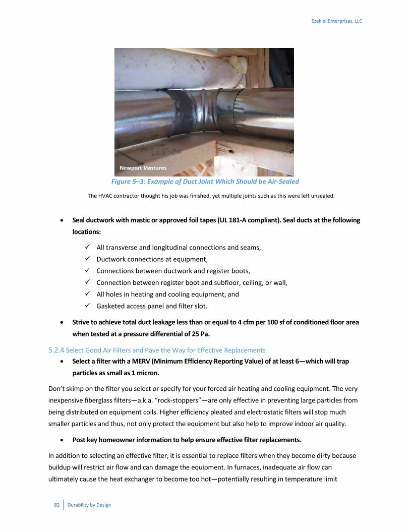
82 Durability by Design
Figure 5–3: Example of Duct Joint Which Should be Air-Sealed
The HVAC contractor thought his job was finished, yet multiple joints such as this were left unsealed.
Seal ductwork with mastic or approved foil tapes (UL 181-A compliant). Seal ducts at the following
locations:
All transverse and longitudinal connections and seams,
Ductwork connections at equipment, Connections between ductwork and register boots,
Connection between register boot and subfloor, ceiling, or wall, All holes in heating and cooling equipment, and
Gasketed access panel and filter slot.
Strive to achieve total duct leakage less than or equal to 4 cfm per 100 sf of conditioned floor area
when tested at a pressure differential of 25 Pa.
5.2.4 Select Good Air Filters and Pave the Way for Effective Replacements Select a filter with a MERV (Minimum Efficiency Reporting Value) of at least 6—which will trap
particles as small as 1 micron.
Don’t skimp on the filter you select or specify for your forced air heating and cooling equipment. The very inexpensive fiberglass filters—a.k.a. “rock-stoppers”—are only effective in preventing large particles from
being distributed on equipment coils. Higher efficiency pleated and electrostatic filters will stop much smaller particles and thus, not only protect the equipment but also help to improve indoor air quality.
Post key homeowner information to help ensure effective filter replacements.
In addition to selecting an effective filter, it is essential to replace filters when they become dirty because buildup will restrict air flow and can damage the equipment. In furnaces, inadequate air flow can
ultimately cause the heat exchanger to become too hot—potentially resulting in temperature limit
Ezekiel Enterprises, LLC

Durability by Design 83
switches to turn off the system or even cracking the exchanger. In air conditioning units, restricted air flow causes the opposite problems—coils which are too cold—causing ice buildup on the cooling coils. This in
turn can lead to equipment damage and water leaks as all of the ice melts.
While the builder or HVAC contractor will install the initial filter, it will be the homeowner who continues
this maintenance task. To avoid problems down the road and help ensure good performance, builders/contractors should clearly post this information at or near the filter location:
Filter dimensions
Initial filter resistance (in inches Water Column) at a specified cfm airflow
Believe it or not, providing this information instead of only the MERV rating gives the homeowner a better
chance of maintaining a well-functioning filter and HVAC system. This is due to the fact that for a given MERV rating, different filters can have much different pressure drops depending on the velocity of the air
flow and the thickness and surface area of the filter. If a builder/contractor wishes to provide a recommended MERV rating for replacement filters, it should be clear that the selected filter must also
adhere to the pressure drop criteria as well. Also, be sure that filter replacement is clearly stated in the homeowner’s maintenance expectations.
5.2.5 Install Local Exhaust Ventilation The 2012 International Residential Code requires exhaust ventilation to the outdoors for kitchens and
bathrooms under the following conditions:
a. When there is no window in the bathroom
b. Above ranges in the kitchen unless: a) Allowed by the manufacturer AND
b) Natural or mechanical ventilation is provided.
Despite these code requirements, which have actually been in place for several years in earlier editions of
the IRC, we often see recirculating range hoods where they are not technically allowed (and also not a good idea) and bath fan ducts “dead-ended” in the attic. Even though a window may exist, during many
times of the year they will simply not be opened due to comfort, allergy, noise, or security issues. Recommended practices to assure effective removal of moisture and energy efficient performance include the following:
Always provide mechanical exhaust ventilation to the outdoors in bathrooms, kitchens, and other
locations prone to moisture, odors, or other air contaminant sources (e.g., a garage shop area).
Ezekiel Enterprises, LLC

84 Durability by Design
Follow these ASHRAE 62.2 guidelines (following) and/or manufacturers’ recommendations when
sizing kitchen and bath exhaust. It’s easier to throttle down the installed flow with a damper—but
difficult/impossible to boost the flow to an undersized system.
Measure and adjust actual flow rates to verify they meet design intent.
Table 5–1: Exhaust Airflow Rates For Local Ventilation
Area To Be Exhausted Continuous Exhaust Rate
Demand-Controlled Exhaust Rate
Bathrooms/Toilet Rooms
> 20 cfm (averaged over each hour)
> 50 cfm
Kitchens Vented range hood—min. 100 cfm capacity or
Any other type of exhaust fan (including downdraft)—min. 300 cfm capacity or
Exhaust fan in enclosed kitchen with min. capacity 5 ACH based on kitchen volume. An “enclosed kitchen” whose permanent openings to adjacent spaces ≤ 60 ft2
Source: ASHRAE 62.2-2013 (with Addendum C)
Use ENERGY STAR labeled ventilation equipment whenever available. Besides being more energy
efficient, these fans have maximum allowable sound levels of 3 sones or less for bath fans and 2 sones or less for range hoods (500 cfm max). This is important. Why? Noisy fans don’t get used.
Control the bath exhaust fan on a timer or humidistat to assure that 1) the fan runs long enough to
adequately remove moisture and 2) the fan is not forgotten and left on too long, consuming more
energy than is necessary.
Range hoods present a special case for consideration. With the increasing frequency of high capacity, “commercial grade” range installations, concern arises regarding the very high exhaust rates that
manufacturers recommend for the accompanying hood. With the substantial depressurization that is likely to occur as several hundred cfm (or more) is drawn out of the home, there is the potential for backdrafting
of combustion equipment that is not sealed—for instance an atmospherically drafted gas water heater.
Installing Local Exhaust Which Actually Works
Simply providing a fan and running a duct to the outside is not enough to assure that the local exhaust system
performs as expected and provides the intended result—especially for bath exhaust where warm humid air is
being removed. Field-tested exhaust flows are very often not even ½ of the fan’s rated flow. Duct runs should
have minimal bends, avoid kinks like the one shown in Figure 5-5, and be sized correctly according to Table 5–4.
Ezekiel Enterprises, LLC

Durability by Design 85
The 2012 IRC requires a source of makeup air equal in volume for range hoods in excess of 400 cfm. Such outdoor air intakes must be dampered and must be automatically controlled to operate simultaneously
with the exhaust hood.
Vent range hoods directly to the outdoors to remove odors
and particulates from the home, rather than simply trapping
or recirculating them.
Follow code or manufacturer’s recommendations for
makeup air for range hoods that exceed 200 cfm, whichever
is more stringent. This will reduce the possibility of
backdrafting combustion contaminants and help assure a safe level of indoor air quality.
5.2.6 Install Whole-House Mechanical Ventilation As energy codes and above-code programs drive homes to become increasingly tighter, it’s critical to install some type of “intentional” whole-house mechanical ventilation. Not only is the turnover of indoor
air beneficial to help remove indoor contaminants and allergens, but it also helps maintain desirable indoor humidity levels in some climates.
In designing, installing, and commissioning a whole-house ventilation system, follow these key provisions drawn from the ASHRAE 62.2 standard:
Select a fan based on its cfm—as rated for 0.25” w.c. static pressure—to assure adequate
airflow and allow for somewhat longer duct runs. Common practice is to pick a fan based on its
cfm at a lower pressure resistance like 0.1” w.c. If the duct layout and other components offer more resistance than this level, the fan doesn’t move enough air.
Make sure duct diameter is at least 4”—preferably 6”. Again, sizing the system for more flow and not less provides some flexibility. If the installed system moves too much air, it can be throttled down to a low flow relatively easily (but the reverse isn’t true). ASHRAE 62.2 recognizes that
supply, exhaust, or balanced systems can all serve as the whole-house ventilation system.
Size, install, and commission a system with the capacity to deliver the ventilation rates shown
below in Table 5–2 (ASHRAE Standard 62.2 Table 4.1a). In reality, builders are well served to educate homeowners on what the system does, how it works, and why it is important. The home’s
“fresh air system” is just like the air-conditioning—the homeowner may not use it all of the time, but he/she should know what it does and when/how to use it. Homeowner know-how is especially
critical in more severe climates with extreme temperature or humidity levels.
ENERGY STAR Range Hood
Specifications:
Maximum Capacity: 500 cfm
Minimum Efficacy: 2.8 cfm/Watt
Maximum Sone Rating: 2 sones
Ezekiel Enterprises, LLC

86 Durability by Design
Table 5–2: Minimum Whole-House, Continuous Mechanical Ventilation Rates (cfm)
Floor Area (ft2) Number of Bedrooms
0–1 2–3 4–5 6–7 > 7
< 1500 30 45 60 75 90 1501–3000 45 60 75 90 105 3001–4500 60 75 90 105 120 4501–6000 75 90 105 120 135 6001–7500 90 105 120 135 150
> 7500 105 120 135 150 165 Source: ASHRAE Standard 62.2
For intermittent operation of the Whole-House Mechanical Ventilation system, maintain a
maximum duty cycle of four hours, meaning that the fan operates at least 1 hour in every 4-hour
segment. For intermittently operating systems, the flow rate (from Table 5–2) must be multiplied by
the appropriate factor from Table 5–3 below to account for periods of fan off time.
Table 5–3: Intermittent Whole-House Mechanical Ventilation Rate Factors Run-Time Percentage in Each
4-Hour Segment 25% 33% 50% 66% 75% 100%
Factor 4 3 2 1.5 1.3 1.0 Source: ASHRAE Standard 62.2
Whole house ventilation can be delivered via the supply-side, central fan integrated system shown in blue and/or
with exhaust fans set to run on a regular basis.
Building America Solution Center/Building Science Corp.
Figure 5–4: Whole-House Ventilation System Types
Whole-house ventilation can be delivered via the supply-side, central fan integrated system shown in blue and/or with exhaust fans set to run on a regular basis.
Ezekiel Enterprises, LLC

Durability by Design 87
The preceding recommendations are admittedly only a sampling of good whole-house mechanical ventilation system design, and readers are encouraged to review the Additional Resources links at the
conclusion of this section for more in-depth guidance.
5.2.7 Design and Install Ventilation Ducts Properly As with providing mechanical ventilation in general, the durability issue at stake relative to ventilation duct work is moisture. Elevated moisture levels and indoor humidity not only damage interior finishes,
but can also lead to mold and rot of structural members. The best ventilation fans and controls simply cannot do their job of managing moisture if the ducts are improperly designed and installed (see
examples in Figure 5–5).
Good and bad duct examples. Good: straight, supported exhaust duct venting to outdoors. Bad: kinked duct with very restricted flow and compromised performance.
Building America Solution Center
Figure 5–5: Right and Wrong Exhaust Duct Installations
Insulate ductwork that runs through cold spaces or exterior wall cavities. In addition, slope ductwork down and away from the fan housing as much as possible so that any condensation will
flow out towards the exterior.
Use straight duct runs. Avoid sharp bends everywhere, but avoid all bends within 2’ of fan to
minimize static pressure and fan noise.
Ezekiel Enterprises, LLC

88 Durability by Design
Adequately support ductwork but ensure that it is not pinched.
Follow ASHRAE 62.2 guidance in sizing ductwork for local exhaust ventilation and whole-house
ventilation according to the rated fan capacity and the length of the run, as shown in Table 5–4.
Verify flow rates with flow hood measurements.
DC Motors—Belt and Suspenders Approach for Getting Good Ventilation Air Flow Rates
Several manufacturers are offering exhaust fans with DC motors. Not only are these fans more efficient
than typical AC induction motors, but many models are also capable of automatically maintaining their
programmed cfm rate even when working against high static pressure levels in the duct work.
Table 5–4: Prescriptive Duct Sizing Chart
Duct Diameter (inches)
Maximum Length in Feet Fan Rating in cfm Certified @ 0.25 in. w.c.
Flex Duct (cfm) Smooth Duct (cfm) 50 80 100 125 150 200 250 300 50 80 100 125 150 200 250 300
3 n/a n/a n/a n/a n/a n/a n/a n/a 5 n/a n/a n/a n/a n/a n/a n/a
4 56 4 n/a n/a n/a n/a n/a n/a 114 31 10 n/a n/a n/a n/a n/a 5 nl 81 42 16 2 n/a n/a n/a nl 152 91 51 28 4 n/a n/a 6 nl nl 158 91 55 18 1 n/a nl nl nl 168 112 53 25 9 7 nl nl nl nl 161 78 40 19 nl nl nl nl nl 148 88 54
8 and above nl nl nl nl nl 189 111 69 nl nl nl nl nl nl 198 133
nl = no limit n/a = not allowed: No use of this duct diameter will meet ASHRAE Standard 62.2 requirements. This table assumes no elbows. Deduct 15’ (5 m) of allowable duct length for each elbow. Source: ASHRAE 62.2
5.2.8 Provide Supplemental Dehumidification or Humidity Controls in Humid Climates In climates that have frequent or extended periods of high humidity, even a properly sized air conditioning system may not operate often enough to adequately maintain acceptable indoor humidity levels. As
discussed throughout this section, high humidity can lead to the formation of mold on surfaces inside the home as well as condensation on building surfaces. Plus, occupant comfort is diminished with high or very
low humidity even if the air temperature is comfortable.
Ezekiel Enterprises, LLC

Durability by Design 89
Figure 5–6: International Energy Conservation Code Climate Zones Map
Source: U.S. Department of Energy
Provide supplemental dehumidification or humidity-based controls that can maintain indoor
relative humidity at or below 60%, for Climate Zone 1 and those portions of 2A and 3A below the
white “warm humid” line in Figure 5–6. Also consider these systems for homes in Zones 3A, 4A,
and 5A which have high performance building envelopes where central cooling will be less
frequent.
Ezekiel Enterprises, LLC
90 Durability by Design
Why? Many parts of the country see at least some muggy weather during portions of the year.
Basements often may be quite humid either during and after construction or during summer months
when the temperature remains low relative to the outdoors thereby elevating relative humidity (RH).
A maximum 60% RH level balances durability in the home, occupant comfort, and operating costs
during these humid periods of the year. During cold winter months lower limits apply (see text box
to the right).
There are several types of dehumidification
systems available:
1. Portable dehumidifiers requiring manual
emptying of condensate buckets unlessplumbed to a drain,
2. Whole-house dehumidifiers that
supplement the moisture removalcapacity of the air conditioning system
and utilize the central ductwork,3. Ventilating dehumidifiers that draw air
into the home, remove moisture, andthen deliver this air to the return side of
the central air handling unit, and4. Variable speed central air conditioning
equipment that includes adehumidification mode to operate based
on indoor humidity levels (regardless ofwhether there is a call for cooling.
The cost of each type of system increases as its functionality becomes more sophisticated, and as with ventilation systems homeowners need some
basic education in using the systems correctly.
Controlling Indoor Humidity and Energy Use—It’s a Balancing Act
Based on research by the U.S. Department of
Energy’s Building America program, the cost of
dehumidifying below 60% RH gets expensive. In fact,
decreasing the setting of a dehumidifier from 60% to
50% can increase energy consumption by a factor of
5! So while indoor RH control is vital in moist
climates to manage moisture and comfort, builders
and their homeowners also need to be aware that
additional drying can ramp up energy bills.
Integrative Design and Construction—Humidity Control and a Dry Envelope
Chapter 4 of this course provides details on the
application of vapor retarders and also minimum
ratios for exterior and cavity wall insulation levels,
when exterior (continuous) insulation is used. The
goal of vapor retarders or a combination of vapor
retarders and insulation ratios is to manage water
vapor by limiting its access to cold surfaces internal
to the wall or to keep the temperature of those
surfaces above the dew point. In other words – to
prevent condensation and moisture accumulation
problems in the wall!
A lot of design assumptions go into the underlying
analysis – notably the indoor relative humidity (RH)
levels. The higher the indoor RH level, the more likely
it is for envelope moisture problems to occur with
any water vapor management strategy. Systems are
needed which can manage and maintain target RH
levels: generally < 40% for winter (or lower in
Climate Zone 5 and colder), and < 60% for summer.
Systems such as supplemental dehumidifiers, HRVs,
and even carefully programmed and controlled
humidifiers – should be part of the HVAC
design…and are also critical to the envelope design.
See Section 4.3 Water Vapor Control.
Finally, home owner education is a major element of
indoor RH control. For example, bath fan usage and
humidifier use and set point are both major factors
in controlling indoor humidity.
Ezekiel Enterprises, LLC
Durability by Design 91
5.3 Recommended Practices—Plumbing A home’s plumbing system is supposed to ensure that water gets to and from the places we need it, at the required temperatures. The very nature of plumbing—moving water around a house—demands that these
systems be viewed with an eye towards durability. Accordingly, a few basic recommended practices follow.
5.3.1 Select More Durable Piping Materials for Supply and Waste Lines Select durable piping materials such as Type L copper, cross-linked polyethylene, or braided
stainless steel for the following types of applications:
o Hard water: For instance, where the water is hard (e.g., has a high mineral content) a
heavier gauge copper—the heavier Type L versus Type M copper—is recommended. CPVC, cross-linked polyethylene (PEX), or polypropylene materials are good alternatives as
well.
o Supply risers: Supply risers for sinks, lavatories, and toilets are usually chrome or cross-linked polyethylene. An upgrade to these materials which is more durable and less likely
to leak is braided stainless steel flexible piping. Depending on the installation, it is usually easier to install as well.
o Appliance supply lines: Braided steel piping is also suitable for ice maker, refrigerator water dispenser, and dishwasher supply lines as well as washing machine hoses. Leaks in
refrigerator and dishwasher lines often go unnoticed for long periods of time because they may not be immediately visible. Such leaks can result in thousands of dollars in
damage to floors, drywall, and even structural members. Increasingly, washing machines are located on first or second floors for convenience. Burst hoses or drainage leaks can
cause significant damage due to the volume of water. High quality hoses and catch pans are a wise safeguard that can minimize damage.
5.3.2 Protect Plumbing Pipes From Freezing This, of course, is a no-brainer, but sometimes inadvertent location of supply or even drain lines can result in frozen pipes during cold weather. Keep all supply lines within the conditioned space and within
interior wall or ceiling cavities. In very cold climates, even pipes located on the warm side of fiberglass insulation in an exterior wall can be subject to freezing.
If you must run the piping in an exterior wall cavity, use a rigid board or spray foam behind
the pipe to minimize infiltration and maximize the R-value separating plumbing from
outdoors. Rigid and spray products offering R6 – R7 per inch are readily available.
Ezekiel Enterprises, LLC
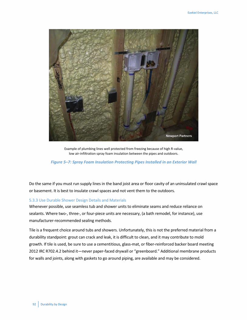
92 Durability by Design
Example of plumbing lines well protected from freezing because of high R-value, low air-infiltration spray foam insulation between the pipes and outdoors.
Figure 5–7: Spray Foam Insulation Protecting Pipes Installed in an Exterior Wall
Do the same if you must run supply lines in the band joist area or floor cavity of an uninsulated crawl space
or basement. It is best to insulate crawl spaces and not vent them to the outdoors.
5.3.3 Use Durable Shower Design Details and Materials Whenever possible, use seamless tub and shower units to eliminate seams and reduce reliance on sealants. Where two-, three-, or four-piece units are necessary, (a bath remodel, for instance), use
manufacturer-recommended sealing methods.
Tile is a frequent choice around tubs and showers. Unfortunately, this is not the preferred material from a
durability standpoint: grout can crack and leak, it is difficult to clean, and it may contribute to mold growth. If tile is used, be sure to use a cementitious, glass-mat, or fiber-reinforced backer board meeting 2012 IRC R702.4.2 behind it—never paper-faced drywall or “greenboard.” Additional membrane products
for walls and joints, along with gaskets to go around piping, are available and may be considered.
Ezekiel Enterprises, LLC

Durability by Design 93
5.4 Additional Resources
ENERGY STAR Version 3.1 Rev 07 HVAC System Quality Installation Contractor Checklist—This checklist
identifies best practices for sizing and designing space heating and cooling systems for new homes. Specific field verification measures are also described.
ENERGY STAR Version 3.1 Rev 07 HVAC System Quality Installation Rater Checklist. This checklist includes several “checks” an energy rater or builder can use to verify several important inputs in a load calculation
are appropriate.
HVAC Quality Installation Specification—Residential and Commercial Heating, Ventilating, and Air Conditioning (HVAC) Applications—Air Conditioning Contractors of America. This industry specification
outlines design, installation, and testing procedures to assure proper performance of residential and commercial HVAC systems. Although the focus is new systems, recommendations are applicable to
existing systems to the extent possible.
The U.S. DOE Building Energy Software Tools Directory provides an extensive listing of public and private
energy-related modeling software. The directory can be sorted by subject, with the subject “Load Calculation” returning numerous tools which include load calculation functionality.
Air Distribution System Design, from the Southface Energy Institute, provides a concise summary of terminology and best practices for designing the air distribution system in residential buildings.
The Building America Solution Center provides extensive technical information on residential building systems and can be navigated by checklist (ENERGY STAR, DOE Zero Energy Ready) or by building system.
See basc.pnnl.gov search for “ducts in conditioned space” under the Building Systems navigator, for instance.
Ezekiel Enterprises, LLC

94 Durability by Design
CHAPTER 6—SUNLIGHT
6.1 General Sunlight is made up of visible light and non-visible radiation such as ultraviolet (UV) and infrared (IR). Depending on the color and surface characteristics of an object, various wavelengths of solar radiation
may be absorbed, reflected, and emitted (i.e., “released”). The more light absorbed and the less heat capacity (i.e., thermal mass), the greater the object’s ability to be heated by sunlight. For example, a dark
driveway becomes much hotter on a sunny day than a light colored concrete sidewalk. Thus, the sun produces two significant effects that attack materials and shorten their life expectancy:
1. Chemical reaction (i.e., breakdown) from ultraviolet radiation and heat 2. Physical reaction (i.e., expansion and contraction) from daily temperature cycles caused by objects
absorbing and emitting heat gained from sunlight
The chemical and physical reactions caused by sunlight can cause colors to fade and materials to
become brittle, warp, or crack. Deterioration can happen relatively quickly (a year or less) or over longer periods of time depending on the characteristics of a material and its chemical composition. In some
cases, materials like plastics that are vulnerable to UV degradation can be made resistant by adding UV inhibitors to the chemical formulation. A prime example
is vinyl siding. As an alternative approach, materials can be protected from sunlight by matter of design (e.g.,
providing shading or using reflective coatings).
UV light is not always bad. For example, there are
portable UV light wands available for use to sterilize surfaces or materials, UV is used to disinfect water and
wastewater, and older style blueprints were created with UV light and special paper that “developed” into
the blue line drawing.
However, almost everyone has witnessed or
experienced the painful effects of UV radiation on skin, which causes sunburn. Consider that the exterior of a
house is like its skin. Therefore, the proper selection of materials determines to what degree the building exterior will be able to withstand the damaging effects of UV radiation similar to the sun protection factor (SPF) for skin. The amount of solar radiation also varies by geography (Figure 6–1),
with the number of cloudless days strongly affecting the dose of UV radiation over the lifetime of a product. As you see in Figure 6–1, even though Florida is a very warm and humid state by Climate Zone
Integrative Design and Construction—Designing With the Sun
Sunlight isn’t just a durability concern—
and in many cases it can be harnessed in
very beneficial ways to provide
wintertime heating and added light to
the indoors.
From an integrated design standpoint,
passive solar heating and daylighting are
design tactics which can increase
building efficiency and homeowner
satisfaction—designers just need to also
account for managing this sunlight.
Example issues are avoiding overheating
solar-exposed spaces and using materials
which can withstand the sunlight
exposure.
Ezekiel Enterprises, LLC

Durability by Design 95
characteristics, its solar radiation is significantly impacted by the amount of cloud cover, as opposed to the Southwest, where sunshine is abundant and clouds are few.
National Renewable Energy Laboratory
Yearly Average Solar Irradiation
Figure 6–1: Yearly Average Solar Irradiation Map
The following section presents a few measures that can help to manage the effects of solar radiation on building materials and systems. For homes, some of the primary problems associated with solar radiation
are color fading, premature asphalt roof shingle failure, and vinyl siding warping. Excessive exposure to sunlight will also cause caulk joints to fail quickly if the proper caulk is not used. In addition, when shining
through windows, sunlight can cause interior colors to fade and possibly unwanted heat gain at certain times of the year.
6.2 Recommended Practices
6.2.1 Size Overhangs to Provide Specific Amounts of Shading As with rain on the building envelope, properly sized roof overhangs can minimize the exposure to solar
radiation and, hence, minimize radiation-related problems. The width of a roof overhang that will protect walls from excessive solar exposure in the summer while allowing heat gain through windows from winter
sunshine depends on where the building is located relative to the equator. The sun is higher overhead in the summer than in the winter. In addition, for any day of the year, at the more northern higher latitudes the sun is lower in the sky than at lower latitudes. Therefore, buildings situated farther south receive
greater protection from the summer sun by roof overhangs, as shown in Figure 6–2.
Ezekiel Enterprises, LLC

96 Durability by Design
Figure 6–2: Building Latitude and its Impact on Overhang Effectiveness
The solar angle factors of Table 6–1 can be used to help determine overhang width to achieve the desired
shading effect on south-facing surfaces. An example calculation which follows shows how the solar angle factor is used.
Table 6–1: Solar Angle Factors (SAF)a
Date
Latitude (degrees North)
24 32 40 48 Key West, FL Charleston, SC New York, NY Victoria, B.C., Can.
To prevent winter shading:
Dec 21 (winter solstice) 1.5 2.0 3.0 5.4 Jan 21 and Nov 21 1.2 1.7 2.4 3.8 Feb 21 and Oct 21 0.8 1.0 1.4 1.9 Mar 21 and Sept 21 0.4 0.6 0.8 1.1
To produce summer shading
Apr 21 and Aug 21 0.2 0.4 0.5 0.7 May 21 and Jul 21 0.1 0.2 0.4 0.5 June 21 (summer solstice) 0.0 0.1 0.3 0.5 Source: Structures and Environment Handbook, 11th Edition, Midwest Plan Service, Iowa State University, Ames, Iowa, 1983. aFactors apply for times between 9:00AM and 3:00PM for winter shading, and at noon for summer shading. Direct south facing orientation is assumed. Latitudes for a sample of other U.S. Cities: Atlanta: 33, Chicago: 41, Denver: 39, Los Angeles: 34.
Ezekiel Enterprises, LLC

Durability by Design 97
6.2.2 Specific Light or Reflective Exterior Finishes in Hot Climates As a second line of defense against damage from solar radiation, light colored materials and finishes can be selected. White is excellent and aluminum reflective-type coatings are even better. Light colors can reduce
summertime cooling load and should reduce energy bills—especially in cooling-dominated climates—by lowering the solar heat gain into the building.
If properly accounted for in cooling load calculations, lighter colored roofing may allow for the use of smaller capacity air conditioning
units. For example, REM/Rate modeling software has a simple “Roof Properties” set of inputs
including the color of the roof covering. Users of this software
or similar programs can very quickly model and observe the
changes which result to the cooling load from switching from dark to light or reflective roof coverings.
The effect of building exterior color on solar heat gain is illustrated in Figure 6–3. It is very important, however, to keep light colored finishes like roofs relatively clean to take full advantage of their reflectivity.
EXAMPLE: DETERMINE ROOF OVERHANG WIDTH TO PROTECT WALL AGAINST SUMMER SUN
Find the overhang length (OL) to shade 6’ of wall below the roof overhang for June through July. The home is
located at latitude of 32 degrees North. It is desired to provide shade for 6 ‘of wall below the overhang at
mid-day (i.e., to bottom edge of windows).
Solar Angle Factor (SAF) = 0.2 (for July 21) from Table 6-1
Wall distance below overhang to shade (WD) = 6’
OL = SAF x WD = (0.2)(6’) = 1.2’
Use a 16” (1.33’) overhang which will provide roughly 6’8” of shading below the overhang.
Determine degree of shading in the winter (using Feb 21) as follows:
WD = OL/SAF = 1.33’/ 1.0 = 1.33’ or 1”.
The selected overhang width will provide no more than about 16” of shading to the wall during the main
winter months of November through February. However, some shading to the top few inches of windows
will occur in the early and late winter months when maximum solar heat gain may be desirable. But, in this
case, the overhang width should not be decreased in the interest of maintaining weather protection of the
wall.
Integrative Design and Construction—Overhangs Affect Sun, Wind and Rain
As the shading calculation example illustrates, overhangs can be strategically
designed to provide shading of windows. Designers should keep in mind that
overhangs also can provide protection to exterior walls from rain (Section
4.2.2) and also increase wind uplift forces on the roof assembly (Section 9.2).
The final strategy for how overhangs are used in a design is largely a function
of the project location.
Ezekiel Enterprises, LLC

98 Durability by Design
Similarly dark colored finishes can be chosen when more solar absorption is a wanted effect —especially in climates where heating is the dominant load.
Figure 6–3: Effect of Surface Coloration on Solar Heat Gain
6.2.3 Protect Reservoir Claddings From Rain Exposure and/or Specify Exterior Wall Materials to Limit Inward Vapor Diffusion A design topic which links moisture management and sunlight is exterior “reservoir” wall materials.
Reservoir cladding materials can absorb bulk water from rain which hits their surfaces and is absorbed. Cladding systems made of masonry, stucco, fiber cement, and wood can all absorb some amount of water.
When these surfaces are wetted (“charged” with water) and subsequently exposed to high levels of sunlight, the cladding materials experience much higher temperatures and vapor pressures. The elevated
vapor pressures drive water vapor towards the exterior but also into wall assemblies, especially if the building interior is at a much lower vapor pressure (i.e., it contains much less humidity due to air
conditioning).
From a design standpoint, overhangs can be used to limit exterior wall exposure to rainfall and water
absorption for these reservoir claddings. If we take away the water source, this problem is managed. See Section 4.2.2 for design guidance on sizing overhangs for moisture protection.
If overhangs are not feasible for aesthetic reasons, a need to reduce wind uplift design requirements, or
other reasons, then the hygrothermal performance of the wall system must be more carefully scrutinized. In fact, even with the use of overhangs, use of reservoir cladding systems warrants more careful
examination of the wall’s treatment of water vapor. Design recommendations include the following.
If water vapor will enter the wall, make sure it can pass all the way through. In other words, if
the wall sheathing, WRB, and exterior insulation (if present) collectively form a highly permeable assembly, then water vapor will be able to migrate into the wall. With this knowledge, we need to
Ezekiel Enterprises, LLC
Durability by Design 99
make sure the vapor can dry to the interior, so interior polyethylene vapor retarders, vinyl wall paper, and other very low perm materials should not be used on the wall interior.
Forming the outer layer of the wall with low or moderate vapor permeance materials can limit
inward vapor migration from the wetted cladding. The low/moderate vapor permeance layer
might be the exterior insulation and/or the WRB. This layer will limit the diffusion of water vapor even when vapor pressure at the cladding is elevated. However, it’s critical to note that adding less
vapor permeable materials towards the outside of the wall will also limit the ability for interior moisture to dry towards the exterior (as in winter conditions). Thus, this recommendation needs
to be directly integrated with the design guidance on insulation levels and perm ratings found in Section 4.3.
Walls at “high risk” from reservoir cladding / solar-driven moisture problems should be
examined more closely with hygrothermal modeling (see discussion in Section 4.3). Risk factors include little/no wall protection from rainfall; high moisture storage capacity (e.g., masonry); and
high solar exposure. Projects in mixed heating/cooling climates are also more challenging because the dominant vapor drive goes in both directions for significant portions of the year.
In addition to this guidance, the Additional Resources includes a reference from Building Science Corporation on reservoir cladding moisture issues.
6.2.4 Specify UV Protective Glazing Materials in High Solar Regions To prevent fading damage to the interior furnishings and to reduce the need for air conditioning, there are
glazing options for windows and doors that block UV radiation. There are myriad different types of glazing and films that can be added or specified for windows providing differing properties for desired
performance. At a minimum, the energy code’s values for window transmittance (U-value) and the solar heat gain coefficient (SHGC) offer some UV protection. If more UV blocking is necessary, films adhered to
the glass will provide this additional UV and/or SHGC protection.
6.2.5 Specify UV Resistant Materials Some materials are naturally UV-resistant, while others require the addition of UV inhibitors in the make-up of the material. For example, concrete or clay tile roofing and Portland cement stucco or brick siding
are naturally resistant to UV radiation and are also resistant to temperature effects compared to other exterior building materials. On the other hand, plastics are prone to “dry rot” (embrittlement from excessive UV exposure) unless UV inhibitors are provided. Plastics are also prone to significant expansion
and contraction from temperature swings. Vinyl siding is a perfect example of how this technology has advanced. Years ago vinyl siding was prone to UV degradation, but is now highly resistant to both cracking
and fading.
Ezekiel Enterprises, LLC
100 Durability by Design
Be sure that UV inhibitors are used in materials that require protection. Many low budget components, such as some plastic gable end vents, may also lack UV resistance. All other factors being equal, choose the
material with the best UV resistance if exposure to the sun is a concern.
6.2.6 Design Landscaping to Provide Shading in High Solar Regions Trees planted near a home along the southern and western exposure provide shading when most needed during the day. Deciduous trees, such as maple or oak, should be used so that winter sun can reach the
building. With appropriate planning, trees can also serve as a wind break to minimize the effects of wind-driven rain. Trees should be planted far enough away from a house to prevent possible damage from limbs
or roots, as well as clogging gutters. (And in fact, trees deserve consideration as a natural hazard in high wind areas. see Chapter 9). Bear in mind that the greatest amount of solar radiation is generally received
between 9 AM and 3 PM. However, shading of only the late day sun (i.e., after 3 PM) is often a preferred and more practical solution for many sites.
Ezekiel Enterprises, LLC

Durability by Design 101
EXAMPLE: DETERMINE LOCATION OF SHADE TREE TO PROTECT AGAINST SUMMER SUN
Use the following equation and the solar angle factors (SAF) from Table 6-1 to determine the appropriate
location of a maple tree (mature height of 60’) southward of a building wall (8’ height) that is to be shaded
during summer months. The building latitude is 40⁰ North.
D = SAF * (ho – hs)
Where:
D = distance between object obstructing the sun at highest point and item to be shaded
ho = height of the object obstructing the sun
hs = height of object to be shaded
SAF = solar angle factor (from Table 6-1)
The following values are given:
ho = 60’
hs = 8’
SAF = 0.4 (from Table 6-1 for May 21 or July 21)
Substituting in the equation above,
D = (0.4)*(60 ft – 8 ft) = 20.8’
Therefore, the center of the maple tree should be located about 21’southward from the wall or windows to
be shaded. Not that the shading at the first day of summer (June 21) will be slightly less due to the higher
solar angle than assumed above. In addition, the tree should not overhang the building at its mature age.
Thus, a distance smaller than about 20’ is not recommended and the distance should be increased for trees
that are larger at maturity.
6.3 Additional Resources BSC Information Sheet 305: Reservoir Claddings for All Climates. Building Science Corporation, May
2014. This information sheet is a concise, four-page discussion of the underlying drivers of reservoir cladding moisture issues with design strategies to manage this issue.
Ezekiel Enterprises, LLC

102 Durability by Design
CHAPTER 7—INSECTS
7.1 General Insects are not just a nuisance; some are also a serious threat to building durability. The following types of
insects are known to damage wooden materials in homes and in other structures:
Termites
Carpenter ants
Wood-boring beetles
Carpenter bees
While all of the above insects can pose a threat to wood-framed homes, termites are the most prevalent and damaging insect. Therefore, most of this chapter addresses issues and practices related to the control
and prevention of termite infestation. Some of the practices for repelling termites, such as eliminating hidden areas that termites can travel through undetected, are also relevant to carpenter ants. Carpenter
ants and wood-boring beetles, like termites, can be treated chemically with insecticides. Carpenter bees can be deterred by plugging entrance holes that commonly occur on wood siding and soffits.
There are about 57 species of termites in the United States that can be placed into two groups: subterranean (ground inhabiting) and non-subterranean (wood inhabiting). Subterranean termites are the most common and are responsible for most termite damage to wood structures. Therefore, this chapter
focuses on subterranean termites. If non-subterranean termites are present, special measures may be necessary
to eliminate them. Fortunately, non-subterranean termites live in much smaller colonies and are much
slower acting than subterranean termites.
One variety of the subterranean termite group is the
Formosan termite, an Asian termite introduced to the United States following WWII. The Formosan termite is
different from the native subterranean termite in that it has a much greater colony size and thus damages wood
at a much faster rate. Estimates state that a colony of Formosan termites will consume nearly 1,000 pounds of
wood per year, whereas other termite varieties will only eat a few pounds annually. Formosan termites are also more likely to survive in a building with minimal ground contact, even though they require a constant
Integrative Design and Construction: Manage Moisture to Manage
Insect Risks
Moisture is an essential ingredient for a
successful colony of wood destroying
insect to take hold. Understanding the
concepts within Chapter 4 of this course
is a critical component is deterring
possible infestation. Much like mold, if
the moisture is not present, most likely
the insects will not be either—get the
water out and away from the home.
Ezekiel Enterprises, LLC

Durability by Design 103
source of water like other subterranean termites. Formosan termites are expanding in range, and are currently found in the Gulf Coast states and southern states along the Atlantic coast.
A termite hazard or probability map, shown in Figure7–1, is frequently used by building code authorities, designers, and builders to determine when certain termite prevention or control methods should be
used. The building codes may vary in delineation of the termite probability zones based on local conditions. The inclusion and degree of termite control and prevention used in a building depends on
the risk of termite infestation, as well as local experience. Talk to neighbors to determine where and when historical infestations have occurred.
In summary, termites like to eat wood and they don’t care if it’s in your home. In areas subject to termite infestation, at least one of the practices listed in Section 7.2 should be used.
Figure 7–1: Termite Probability (Hazard) Map
Source: HUD Durability by Design (2002); original source unknown
Ezekiel Enterprises, LLC

104 Durability by Design
7.2 Recommended Practices There are basically three techniques for controlling or preventing termite damage:
Chemical soil treatment or baits,
Termite shields, and
Use of termite resistant building materials.
These measures can be combined for enhanced protection certainly, and in higher risk areas this
redundancy can be very important as treatments and termite shields are unlikely to be 100% effective in all
cases.
7.2.1 Choose Appropriate Chemical Treatment Types Chemical treatments for termite control come in a variety of forms. Generally, chemical treatments for termites
include soil termiticides, termite baits, and treated wood products. This section will only discuss soil and bait
termiticides.
Chemical soil treatments are designed to form a protective barrier around a structure to prevent termites from contacting or penetrating the building. Soil treatments are the most common form of termite control
used by the building community. Commercially, there are an assortment of soil treatments that, by various biological means, kill termites or repel them. Termiticides are generally preferred over repellents.
Termite baits are encapsulated termiticides designed to lure insects to the bait, and then—once eaten—kill the termites. The poisons are designed to act slowly so as to not repel the insect and to facilitate the
consumption and transport of the poison to the nest. Other termites ingest the termiticide from the insects that feed directly on the baits through secretions emitted by the original feeders.
Application
Chemical soil treatments are generally applied to the soil around the foundation of a home to act as a
shield against termites. The treatments are performed prior to pouring the slab or foundation, shortly after foundations and slabs are poured, and at periodic intervals for the life of the structure. Directions vary
according to the chemical used, but these locations are of special concern for chemical application:
Rules of Thumb
Prevent subterranean termite access
by diverting water away with properly
functioning downspouts, gutters and
splash blocks.
Store firewood at least 20’ away from
the home.
Keep mulch at least 15” from the
foundation
Indoors, homeowners should reduce
humidity through proper ventilation
of crawl spaces, attics and basements
to avoid attracting subterranean
termite swarms.
Source: www.pestworld.org/pest-
guide/termites/subterranean-termites/
Ezekiel Enterprises, LLC
Durability by Design 105
Soil along foundations and crawl spaces;
Areas of soil disturbance such as bath traps which may create areas of lower resistance to
movement;
Soil under appurtenances such as attached slabs and porches;
Soil in inaccessible or concealed spaces; and
Soil in proximity to slab or foundation penetrations due to plumbing, wiring, etc.
Termiticides are applied by one or more of the following methods: trenching around a foundation and
flooding the trench with a sprayer; inserting a rod at periodic intervals around a foundation and injecting the chemical in the soil; and drilling holes in masonry slab or foundations and injecting the chemicals into
the soil through the holes. Factors such as access to targeted areas, presence of landscaping, and the chemical employed dictate the treatment option used by the pesticide applicator. A certified pest control
operator (PCO) is required for application of most termiticides.
Performance of termiticides varies considerably with climate, soil type, structure design, and homeowner practice. Locations with frequent precipitation, impermeable or very permeable soils, or great soil
disruption from landscaping activities will require frequent reapplication in order to maintain termite-resistive properties.
Termite baits are applied to the ground at intervals around the home as prescribed by the product label. Some bait systems employ only a cellulose bait that requires frequent monitoring. Once termite activity is
detected, a poison is inserted into the bait housing. Other bait systems contain both termite lure and poison in one formulation. The key to satisfactory performance in a bait system still is proper monitoring
and placement. Do-it-yourself termite bait kits are available to the general public, but the temptation is to purchase too few and monitor the baits infrequently, thus severely hampering their effectiveness. This
requires much diligence on the part of the homeowner. Many pest control operators offer bait systems which better assure proper bait placement and monitoring.
Reapplication and Inspection Services
Chemical termiticides have a limited life because of leaching or chemical degradation. In addition,
homeowner activities such as disruptive landscaping tend to limit the effectiveness of chemical treatments. Therefore, many homeowners opt to employ a termite service offered by pest control operations (PCO).
Typically, a contract with a PCO involves an initial treatment of the structure with a chemical termiticide or bait system, followed by an annual inspection of the structure with periodic retreatment performed
when required. PCO warranties may offer free retreatment if infestation is detected along with some coverage of repair costs, depending on the specific plan. The benefits of an inspection and treatment
service include periodic inspection of a home by knowledgeable technicians and quick remedial action
Ezekiel Enterprises, LLC

106 Durability by Design
when infestation is detected. A client can be better assured of a competent applicator if the PCO is a member of the National Pest Management Association (NPMA). NPMA promulgates the standards that
constitute proper treatment of buildings.
7.2.2 Specify a Termite Shield System A termite shield is placed between a masonry foundation and wood framing to prevent termites from gaining access to the wood framing components. Termite shields (Figure 7–2) must be of termite-resistant
materials such as metal or concrete. Some termites are able to chew through plastics and thin metals. Also, any seams in a termite shield must be soldered or otherwise sealed.
Since termite shields require a high degree of care in installation, they are best used in combination with
soil treatment. They should always be used when there are potential hidden pathways. Construction
types known to create hidden pathways for termites include slab-on-grade (except monolithic slabs of good construction), masonry construction, and brick veneer construction.
Hidden pathways allow termites access to wood materials through pathways that cannot be detected during periodic inspection. When there are no hidden pathways in construction, subterranean termites
can be easily detected by the presence of shelter tubes or tunnels that are made of mud to protect them from light and keep them moist. Because termite shields are difficult to install on slab-on-grade
construction or split-level construction, other methods of termite protection (e.g., soil treatment) are generally preferred for these types of foundations. It is also noteworthy that termites can gain hidden
access through cracks as small as 1/32” wide. Therefore, if concrete is used as a barrier to termites, it should include welded wire fabric or sufficient reinforcement to control cracking. Examples of concrete as a termite barrier are illustrated in Figure 7–3.
Ezekiel Enterprises, LLC

Durability by Design 107
Figure 7–2: Use of Termite Shields
Figure 7–3: Use of Concrete as a Termite Barrier
Ezekiel Enterprises, LLC

108 Durability by Design
7.2.3 Use Termite Resistant Building Materials for Added Protection Wood can be protected against termite damage by use of preservative treated wood (e.g., ACQ, CA-B, CA-C or Borate). CCA was used in residential construction up until 2004 when it had been voluntarily
discontinued. Using treated lumber to frame a home can add hundreds or few thousands of dollars to the price of a typical home. Such a drastic measure, however, is only used in particularly severe termite hazard
areas like Hawaii.
As an alternative, preservative-treated wood may be used in isolated locations such as foundation sills and
floor framing directly above the foundation. This practice is particularly appropriate for crawl space construction and for basement construction when ceilings are finished such that these elements are not
easily inspected for infestation. Alternatively, naturally decay-resistant wood (e.g., heartwood of redwood and eastern red cedar) may be used, but at even greater expense than preservative treated lumber. For
this reason, materials such as galvanized cold-formed steel may be a cost-effective alternative and are frequently used in Hawaii to complement or compete with the use of preservative treated wood. Concrete
and masonry building materials are favored alternatives in areas such as Florida.
Ezekiel Enterprises, LLC

Durability by Design 109
CHAPTER 8—DECAY AND CORROSION
8.1 General At a moisture content of greater than 25 %, wood is subject to fungal attack or decay. Decay will be rapid when the temperature is in the range of 70 to 85⁰F. The potential for wood decay when exposed to the
outdoors, therefore, varies in accordance with climate (refer to Decay Hazard Map, Figure 4–2). However, wood exposed to excessive moisture within a building assembly in any climate, particularly one with a low
drying potential (see Chapter 4), will grow mold and rot.
There are essentially three options for preventing decay of wood which may be exposed to the elements:
Protect (or separate) wood from moisture
Use naturally decay-resistant wood
Use preservative treated wood
Of equal concern is the corrosion resistance of fasteners that must hold wood joints firmly together.
Corrosion of insufficiently protected metal fasteners can eventually lead to complete failure of key
fasteners which support assemblies like deck joists.
Finally, it is important to consider cost-effective alternatives to wood that offer potential durability and
maintenance benefits. In combination with measures presented earlier in this course, particularly in
Chapter 4, recommendations in the following section should address the major concerns regarding
durability of wood construction.
8.2 Recommended Practices
8.2.1 Design to Maintain Minimum 8” Clearances to Protect Wood from Ground Moisture One of the oldest and most reliable practices to prevent wood and other moisture sensitive materials from decay is to separate the wood from the constant uptake of moisture from the ground. Decay conditions can occur when wood is in direct ground contact or when moisture wicks through other materials such as concrete or masonry. Some well-known details for separation of wood from ground moisture are shown in Figure 8–1.
Most building codes require a minimum of 6” clearance between untreated wood and the exterior grade.
A minimum of 8” clearance between untreated wood and the exterior ground level is recommended
in this course. In other conditions shown in Figure 8–1, ground clearance recommendations vary (e.g.,
floor beams in crawl spaces are required to have a minimum 12” clearance to interior grade as much for
reason of access as for moisture protection).
Ezekiel Enterprises, LLC

110 Durability by Design
Figure 8–1: Details to Separate Wood from Ground Moisture
8.2.2 Match the Treatment Level of Preserved Wood and Fastening Systems to the Application and Exposure There are often situations where wood cannot be adequately separated from ground moisture or protected from exterior moisture sources. In these situations, either naturally decay-resistant wood or preservative-treated wood must be used. In some cases, wood alternatives may be considered, such as
Ezekiel Enterprises, LLC

Durability by Design 111
plastic porch posts with metal pipe inserts, plastic decking, concrete posts or piers, or plastic lumber composites.
For preservative treated wood, the American Wood Protection Association (AWPA) maintains the Use Category System (UCS), first introduced in 1999 and used to define a range of usage categories, or
biodeterioration hazard levels, for treated wood products. The UCS covers a wide range of conditions spanning residential to marine construction, with most residential applications generally found in use
categories 2 through 4. Table 8–1 below summarizes typical residential Use Categories and Applications, drawn from specification recommendations for Southern Pine.28
Table 8–1: Common Use Categories for Preservative Treated Wood in Residential Applicationsa
Use Category Typical End Use Applications
(not all inclusive) Commonly Used Preservative
Systems
UC2 Above Ground, Interior: Damp
Sawn interior framing, flooring, furring strips, millwork/trim, sill plates, roof trusses, subflooring
Borates, Carbon based, Copper azoles and quats
UC3A Above Ground, Exterior: Protected
Sawn painted/coated fascia, fence pickets, gazebo material, millwork/trim, siding
Carbon based, Borates, Copper azoles and quats
UC3B Above Ground, Exterior: Exposed
Sawn decking, deck joists and beams (not subject to frequent wetting); deck cross-bracing, railing components, stair stepping, unpainted fascia, fencing, gazebo material, millwork/trim, siding, floor trusses,
Copper azoles and quats, Carbon based
Glulam beams for decks, gazebos, etc.
Copper Naphthenate, Oxine Copper
UC4A Ground Contact / Freshwater: General Use
Sawn deck, fence and general-use posts; deck joists and beams (ground contact) and stair stringers; gazebo supports;
Copper azoles and quats
a. Note that additional applications and preservative systems may apply in residential settings. This table is intended to relate common residential design scenarios for preservative treated wood, and is based on Southern Pine. For other wood species, treatments and applications should be confirmed with the material supplier.
The table above serves as a quick reference, with conditions 3B and 4A being the most common for pressure-treated Southern Pine lumber. More in-depth information on the Use Categories, preservative
retention minimums by product/end use, and specification details are available from AWPA Standard U1 and the Southern Pine Council (see Additional Resources section at the end of the chapter).
28 Pressure-Treated Southern Pine, Standards, Specifications, Applications. Southern Pine Council, 2014.
Ezekiel Enterprises, LLC

112 Durability by Design
When a residential design includes preservative treated wood, there are several basic recommendations to help assure good durability performance.
Specify Ground Contact (UC4A) pressure-treated lumber for applications which more closely fit this
condition, as opposed to Above Ground (UC3B). Typical applications to specify UC4A instead of
UC3B are:
o deck joists and deck beams in close proximity to the ground
o deck decking, joists, and beams subject to frequent wetting from moisture sources like hot tubs
o stair stringers with ground contact or in close proximity to the ground
Verify that treated lumber delivered on site matches the specification and the Use Category. For example, if deck joists close to the ground are specified to be UC4A, field verify that this is the Use
Category for the lumber, as listed on the lumber’s plastic end tag or the ink stamp.
Select fasteners and connectors with the appropriate corrosion resistance given the type of
preservative treated wood they’re being used with. Corrosion resistance of fasteners and connectors used with treated wood products is not a new issue, but has gained increased
emphasis since the phase-out of Chromated Copper Arsenate (CCA) in residential applications in 2004. The alternative treatments have generally been shown to be more corrosive. The building
application should define the Use Category, and this information is used to select the preservative treated wood system. Based on the preservative treatment being used, the wood supplier should
be able to provide: the chemical retention level, whether or not ammonia was used, and ultimately a connector/coating recommendation. If the wood supplier cannot provide a connector/coating recommendation, the preservative treatment information can be
crossreferenced with the fastener/component supplier’s recommendations. For example, Simpson Strong-Tie offers a Technical Bulletin on Preservative Treated Wood which includes recommended
coatings as a function of the preservative type and the application’s exposure (see Additional Resources).
Beyond following this selection and specification process, several other rules of thumb apply for connectors/fasteners used with preservative treated wood:
o Hot-dip galvanized or stainless steel fasteners/connectors are recommended for use with preservative treated wood. Electroplated, electro-galvanized, and mechanically galvanized
coatings should not be considered to be hot-dip galvanized.
o The thicker the galvanized coating, the longer the expected service life of the fastener,
connector, anchor, or other hardware.
Ezekiel Enterprises, LLC

Durability by Design 113
o Hot-dip galvanized fasteners (like nails) should be used with hot-dip galvanized connectors (like joist hangers). The same is true for stainless steel. Hot-dip galvanized components
and stainless components are dissimilar metals and should not be used with each other.
o To be more conservative in aggressive environments, specify stainless components. Note
that cost and product availability are both significant considerations in the use of stainless components.
8.3 Additional Resources American Wood Protection Association Standard U1-14, Use Category System: User Specification for Treated Wood. http://www.awpa.com/standards/U1excerpt.pdf
Pressure-Treated Southern Pine, Standards, Specifications, Applications. Southern Pine Council, 2014.
Preservative Treated Wood Technical Bulletin, Simpson Strong-Tie,
http://www.strongtie.com/ftp/bulletins/t-ptwood08-r.pdf
Ezekiel Enterprises, LLC

114 Durability by Design
CHAPTER 9—NATURAL HAZARDS
9.1 General There is perhaps no area of the United States that is
spared from natural hazards. Coastal areas experience
hurricanes and flooding; “tornado alley” spans the central
part of the country from the Gulf Coast to North Dakota;
earthquake-prone areas are most notably in California, but
significant faults also exist in Hawaii, Alaska, South
Carolina, and portions of Missouri, Arkansas, and
Tennessee; wildfire risk is highest in the West, Southeast,
and upper Great Lakes, but structures have been lost
across the country due to wildfires; and the frequency of
severe thunderstorms and hail is high or very high in at
least half of the country!
Although we typically think of durability as “standing-the-test-of-time,” a durable home must also be able to withstand risks in the form of disasters that may last for only minutes or hours. This section of the course therefore provides guidance regarding design and construction methods that will improve a home’s ability to withstand the forces exerted upon it by natural disasters.
Aside from the dialogue about the exact causes of extreme weather events, there is little debate that extreme
weather events are becoming more frequent. The Institute for Business and Home Safety, which has tracked the occurrence of disasters and consequent costs to
insurance companies since 1950, has shown an increase in the quantity and severity of events over just the past 23 years. Based on industry risk analysis, for example, the number of states experiencing insurance
claims valued at over $2 billion rose from only 7 states between 1990 and 1999, to 24 states between 2010 and 2013.29
Local building codes—typically derived from model national codes—establish the minimum level of disaster mitigation that is legally allowed from the standpoint of public safety and general welfare. However, although such measures may be good for the whole, they may not be optimal for any one
29 Verisk Analytics. The Financial Effects of Natural Disasters—online tool for mapping disasters by type and by timeframe. http://www.verisk.com/property-claim-services/natural-disasters.html, last accessed August 2014.
The chance of homeowners experiencing a
natural disaster is far greater than winning
the lottery. Should they be inclined to buy a
lottery ticket to offset some of the cost of
building their new home, they are taking a
large risk with a small part of their income
for an extremely small chance of winning a
big sum of money.
Viewed in this context, doesn’t it make more
sense for home buyers also to consider
investing a modest sum of money (rolled
into the mortgage) to better their odds of
their home surviving a future extreme
weather event (probably more likely than
the lottery) and thus, enjoy the benefit of a
more resilient home for years to come?
This chapter is based on the expectation
that the answer to this question is “YES.”
Ezekiel Enterprises, LLC

Durability by Design 115
individual’s circumstances. The building code also maps hazard areas by region when in fact the degree of risk may vary based on site-specific characteristics. For instance, homes located in very open terrain may
face greater threat from high winds. Some homeowners may want additional protection from potential damage—especially if the cost of hazard insurance is quite high. Furthermore, it almost always is less
expensive to include measures when building a new home rather than go back and try to retrofit later. In short, there are many strong reasons to consider additional, cost-effective disaster mitigation measures for
new homes.
The following sections of this chapter outline the major natural hazards and a subset of recommended
mitigation measures for each. Note that these measures are only a sample of recommended measures that generally offer a
significant improvement for a modest cost. Additional
resources for disaster mitigation are then listed at
the end of the chapter.
Safer Stronger Homes – HUD 1993, Crandell 2005
Figure 9–1: Examples of Roof and Building Damage From High Winds
9.2 Recommended Practices—High Wind Regions High wind regions cover a large portion of the United States While we associate the Gulf and Atlantic
coasts with hurricanes and the Midwest with tornadoes, severe thunderstorms can happen anywhere. Microbursts and “derechoes” have become familiar terms and cause very significant damage in localized
areas. Roof damage is one of the most frequent types of damage and particularly serious because it is often coupled with significant water damage.
9.2.1 Enhance Roof and Wall Sheathing Connections: Use Deformed Nails or Screws for Enhanced Roof and Wall Sheathing Connection. Studies show as much as a doubling of withdrawal capacity, if not more, when deformed shank fasteners
are used instead of smooth shank (assuming same size shank and adequate head size). Screws provide even greater holding power. Either deformed nails or screws are therefore very effective strategies in any area subject to high winds, with the added costs typically less than $250. Of course installation quality is
still critical, as overdriving nails into sheathing can significantly reduce capacity and nails missing framing members, whether ring shank or not, will offer no uplift resistance. However, not all ring shank nails are
Ezekiel Enterprises, LLC

116 Durability by Design
equal; as a minimum recommendation, use ring shank nail specifications as found in the ICC 600 Standard for Residential Construction in High Wind
Regions, Section 309.3 (www.iccsafe.org).
A key benefit of the improved sheathing pull-off strength, beyond occupant
safety and limiting potential wind-debris impacts to neighboring homes, is that loss of even one roof sheathing panel in a major wind-driven rain event causes
disproportionate damage to a home. Just one missing sheathing panel can allow a home to become inundated with water, which compounds the insurance loss
in addition to displacing the residents.
Insurance Institute for Business and Home Safety
Figure 9–2: Ring Shank Nail
9.2.2 Select a Roof Shape and Slope to Minimize Potential for Wind Damage Hip roofs and gable roofs which have a pitch between 5:12 and 6:12 have been shown to perform
exceptionally well during severe wind events (Figure 9–3). Moderately pitched hip roofs provide a more “streamlined” building compared to other roof geometries regardless of which direction the wind blows.
Moderate roof slopes aren’t as prone to uplift that can pull off entire roofs and they also limit the lateral force that can cause building collapse.
An optimal roof slope can reduce lateral wind load by as much as a factor of three and reduce uplift loads by 50% or more!
U.S. HUD
Figure 9–3: Roof Pitches and Their Implications for Wind Forces
Ezekiel Enterprises, LLC

Durability by Design 117
9.2.3 Use Wind Resistant Roofing and Enhanced Underlayment in High Wind Areas as Required by the IRC Standard asphalt composition roof shingles, the most common roof covering for residential buildings, vary in their capability to resist wind loads. Using better performing shingles can help prevent roofing damage leading to potential moisture intrusion and more serious consequences to building contents. In hurricane-
prone and high wind areas, the IRC requires that shingles must be rated to meet hurricane level wind speeds according to ASTM Standard D 7158 classes G or H or ASTM D 3161 class F. Shingles meeting ASTM
D 7158 Class H are rated for wind speeds as high as a Category 4 hurricane (or very severe thunderstorm downburst). Selecting
higher performing shingles is advisable in all wind regions for durable roof construction.
Using a shingle rating greater than that required by code, if available, will also provide some relative benefit in limiting
damage. Further, designers and builders should also be careful to cross-reference shingle ratings with the locally applicable, code-
mandated wind speeds. As a matter of practical importance, following the shingle manufacturer’s installation instructions for
high wind conditions and also ensuring a good adhesive tab seal between shingle courses are crucial to durable asphalt shingle
roofs. Recent insurance industry research indicates that “SBS polymer modified shingles” are most likely to provide a durable roof installation.
Figure 9–4: Examples of Roof Covering Loss
Underlayment and Flashing—The IRC
requires a minimum of a single layer of 15# felt lapped 2” for composition shingle
roofing on slopes ≥ 4:12; a double layer of underlayment is required for shallower
pitches. Flashing is required in valleys, at sidewalls, and wherever there is a roof
penetration such as chimneys and vents. In high wind areas, a 4” overlap, reduced
fastener spacing (12” grid pattern with 6”oc at lap joints), and plastic or metal cap nails are required.
Figure 9–5: Sheathing Seams Covered With Bituminous Tape
Ezekiel Enterprises, LLC

118 Durability by Design
Because non-adhered membrane-type underlayment (e.g., 15# felt) isn’t intended to be an exposed water-resistant barrier under high wind conditions, it does not provide a durable back-up should roof
shingles become damaged and torn off the roof from wind. Therefore, in high wind regions it’s good practice to seal the roof deck below. There are several options including taping of the seams of the
sheathing with a bituminous tape (Figure 9–5). For even further protection in the event of shingle damage or loss, the entire roof can be covered with a self-adhering membrane. As another alternative, a recent
test at the IBHS Research Center on full-scale roofs demonstrated that two layers of ASTM D226 Type II or ASTM D4869 Type IV underlayment can provide excellent water intrusion resistance without requiring
application of tape or a self-adhering membrane.
9.2.4 Select and Locate Trees to Avoid Damage to Property While trees can be very useful in protecting materials and finishes from harsh sunlight (Chapter 6) and reducing cooling loads in the summer (Chapter 5), and even sheltering buildings from high winds—there
are considerations to address when planting trees around a home (or situating a new home among existing trees) in high-wind regions. Some basic guidance can be gleaned from looking at those species,
characteristics, and conditions which have demonstrated a successful survival rate under previous severe storms and hurricanes.
1. The following species have performed well during Florida hurricanes over a 10-year period between 1995 and 2005: live oak, sand live oak, and sabal palm. Crape myrtle and bald cypress
also have withstood major storms. 2. Select trees that attain a maximum height of 30’ or less, and display open branching patterns.
Such trees present less surface area for the wind to blow against and allow the wind to pass
through the canopy rather than exert pressure that can topple it. 3. Plant trees in groups rather than individually, but allow enough spacing between them for a
strong root system to develop. Recommended distance between trees is approximately the expected diameter of the canopy at maturity.
4. Avoid trees that have shallow root systems such as Bradford pears. Likewise, avoid species that become brittle and break or split easily when mature. Examples include poplars and aspens.
5. Selective pruning of branches in tree canopies by a knowledgeable arborist can thin the crown and reduce wind loads on the tree.
9.3 Recommended Practices—Flood Prone Regions Flooding can be the most serious consequence of a hurricane as was recently the case for the Gulf Coast
(Katrina) and New York/New Jersey (Sandy). Moreover, flooding and severe damage can occur quite a distance from where a hurricane or tropical storm initially makes landfall, as was seen in Pennsylvania,
Upstate New York, and Vermont with storms Irene and Lee. However, hurricanes are certainly not the only cause of flooding. In many communities, flooding can be a frequent occurrence when rapid winter snow
melt combines with substantial rain events. Thus, buildings in coastal regions as well as low lying areas
Ezekiel Enterprises, LLC

Durability by Design 119
adjacent to rivers and streams can be susceptible to significant property damage. Given that upstream development and land-use changes can alter flood elevations at a given site, it is recommended to err to
the conservative when it comes to the risk of flooding.
9.3.1 Raise the First Floor Level at Least 1’ Above the Base Flood Elevation (BFE) in A Zones and at Least 3’ above the BFE in V Zones FEMA has classified different parts of the country according to their risk of flooding. V Zones are those subject to the greatest risk and are typically those properties located directly on the coast. As such, they
are exposed to the largest waves during a hurricane storm surge and thus, have the highest recommended “freeboard” or elevation above the 100 year Base Flood Elevation. A Zones are the second highest risk area
and are typically those properties located near a lake, river, stream, or other body of water.
Raising the first floor level at least 1’ above BFE in A Zones and at least 3’ above BFE in V Zones greatly
enhances the flood resistance of a home. This measure will keep wood and finish materials high enough to prevent or limit water damage and the subsequent problems this causes. In V Zones, coastal A Zones
where surge can be a problem or in riverine areas where flood waters may be moving swiftly, open foundations and extra elevation are critical to allow a clear area for flow through. Figure 9–6 illustrates
these concepts. Further, flood maps for all regions of the country are available at https://msc.fema.gov/portal.
FEMA: http://www.region2coastal.com/coastal-mapping-basics
Figure 9–6: Diagram of Flood Zones and Base Flood Elevation
Ezekiel Enterprises, LLC

120 Durability by Design
9.3.2 Install a Sump Pump in Basements. Sump pumps can remove incoming water due to severe storms or other heavy sources of exterior water near the home’s foundation. Adding the sump pump is crucial but
the system is made even more effective by the following measures.
Diverting water at least 10’ away from the foundation. Too many sumps simply discharge the
expelled water right back against the foundation! See Figure 9–7.
Provide battery backup so that the sump will operate during a power outage.
Ensuring that the foundation’s perimeter drain
system feeding into the sump pit is installed properly to prevent clogging over time (e.g., gravel
with filter fabric as shown in Figure 3–4).
Air sealing the cover of the sump pit to avoid
indoor air quality problems from radon, odors, etc.
Integrative Design and Construction: Foundation Design in
Flood-Prone Regions
Elevated foundations in flood prone
regions have the critically important job of
protecting the home from flood waters,
whether in the form of rising water or
flowing water. These same
foundation/floor systems also need to
manage heat loss/gain as well as chronic
moisture from outdoor humidity.
In this case the integration of these
functions clearly starts with the flood
resistance of the structure. From this point,
the builder and designer should identify the
best ways to insulate the home’s
foundation and prevent cooled surfaces
from developing chronic condensation. See
Chapter 4 for a discussion of unvented
crawl space foundations.
Figure 9–7: Sump Pump Discharge Right Next to Foundation
Ezekiel Enterprises, LLC

Durability by Design 121
9.4 Recommended Practices—Seismic Regions While the most severe and frequent earthquakes have occurred in California and portions of Alaska and Hawaii, damaging earthquake activity has been experienced in many other parts of the United States. We
have seen the major amounts of damage that can occur in a very short period of time. Although rare, very strong quakes can give rise to tsunamis that cause their own damage and fatalities. Just as for high wind
and flood prone regions, the International Residential Code (IRC) maps seismic risk regions of the United States and prescribes minimum construction and design requirements for those buildings constructed in
high risk areas. However, there are some modestly priced measures which builders and designers can apply to provide added seismic protection to meet or exceed code.
9.4.1 Reinforce Connections Between Building Components and Assemblies to More Reliably Transfer Loads Along a Continuous Path to the Foundation. This measure not only provides protection in earthquake regions, but also in areas prone to high wind
events. Ensuring that all assemblies from the roof to the foundation are securely connected to one another is simply good building practice and in most areas is simply required by code. Figure 9–8 shows some of
most important connections.
To improve a home’s durability in seismic zones of moderate or greater risk, design for the next higher risk
category for seismic (or wind) requirements as specified in the 2012 IRC. This will involve strengthening the load path connections beyond the code-minimum levels, and will also afford increased wind resistance for
the home.
Ezekiel Enterprises, LLC

122 Durability by Design
Figure 9–8: Continuous Load Path Diagram
Source: Insurance Institute for Business and Home Safety
9.4.2 Secure Water Heaters, Space Conditioning Equipment, and Other Heavy Items Preventing heavy objects in your home from toppling or falling not only protects them from damage but
also may protect occupants from injury. Some items like water heaters and water tanks would not only be damaged themselves but also might cause additional damage due to water or possible fire. Some of the
items to consider include refrigerators, freestanding ranges or wood stoves, computers, televisions, and shelving. In basements or unfinished spaces, large equipment can be strapped to the wall and/or bolted to
the floor. In finished areas, freestanding shelving and bookcases can be securely screwed to the wall. It is also recommended to put heavier or breakable items on lower shelves.
9.5 Recommended Practices—Wind-Driven Rain Areas Almost all parts of the country experience heavy rain storms accompanied by high winds. This can drive rain behind siding and around windows and doors where it can become trapped in wall cavities and lead
to moisture damage and mildew and mold. To view the intensity of wind-driven rain levels around the United States, see Figure 4–10.
Ezekiel Enterprises, LLC

Durability by Design 123
9.5.1 Use Enhanced Water-Resistive Barrier (WRB) Materials and Best Flashing Practices to Keep Water Out of Walls and Buildings. Although a WRB and flashing details are required by the building codes, certain practices can increase
their effectiveness in extreme wind-driven rain events. Under abnormal conditions, such as a hurricane or severe wind-driven rain event, quality of installation becomes particularly important because the
consequence of any defects are magnified. Also, one can enhance WRB installation and flashing details following recommendations and resources cited in Chapter 4. For example, overlapping of joints can be
increased (i.e., 4” instead of 2” lap) and joints sealed. Also, WRB materials can be more carefully selected by requesting full-scale assembly water-penetration test data from the manufacturer (not all
WRB materials or assemblies will pass such testing).
9.5.2 Understand, Verify, and Specify Appropriate Wind Ratings for Windows Standardized wind-driven rainwater penetration tests are conducted with wind pressures that are only 15 to 20 % of the design wind pressure. A code-minimum fenestration product is based on a test wind
pressure that corresponds to about a 35 mph wind speed—equivalent to a common thunderstorm gust. Consequently, such doors and windows are likely to leak during significant wind events, even when they
are properly installed and flashed.
There are several important implications from this “disconnect” between water penetration tests and
design wind pressures:
1. Good window flashing practices (Chapter 4) aren’t just “extra credit.” They provide a necessary
belt and suspenders type of approach to limiting (or mitigating) water infiltration through and around windows. Of particular importance to address this issue is the use of pan flashing to remove water that penetrates the window unit itself, not necessarily the flashing of it.
2. At a minimum, builders and designers should verify that glazing in windows and doors meets requirements for the locally applicable wind pressure loading (design wind pressure). Window
labeling and certification should indicate the appropriate wind pressure rating.
9.6 Recommended Practices—Hail Prone Areas Like wind-driven rain, hail is most likely to occur in areas susceptible to severe thunderstorms. It is
probably the roof covering material that will suffer the most from the impact of hail. Hail can cause damage that significantly reduces the life of roofing shingles and roof causes leaks to develop.
9.6.1 Install Impact Resistant Roof Coverings Having a Class 4 Rating When Tested to UL 2218 or FM 4473. Most manufacturers have a line of shingles that have been tested to withstand significant hail events. The
test standards typically cited are UL 2218 and/or FM 4473. UL 2218 is primarily intended for flexible roof covering materials while FM 4473 tests the impact resistance of rigid materials such as wood shakes, slate,
and metal roofing. There are four classes of impact resistance with Class 4 having the highest performance. Recent IBHS research has shown that the most durable and hail resistant Class 4 asphalt shingles are those
Ezekiel Enterprises, LLC

124 Durability by Design
made using polymer modified asphalt. In some states such as Texas, insurance premium discounts are available for roof coverings meeting this standard, which helps make these products more cost-effective.
This category of roof covering material is also usually more wind-resistant as well.
9.7 Recommended Practices—Wildfire Regions In recent years, property damage and loss of life due to wildfires has been significant and on the
increase, primarily due to more people living in wildland-urban interface regions. The U.S. Forest Service reported that over 30% of the country’s housing units are located in these high risk areas. Over the past
ten years especially, there has been a steady increase in wildfires exceeding 50,000 acres.30 Although the Wildland-Urban Interface Institute developed a map of the severity of fire risk across the country,
serious fires have broken out in what was once considered low or moderate risk areas. As a result, the National Institute of Standards and Technology is developing something akin to the use of the Richter
scale for earthquakes—but for wildfire—to better predict and characterize the risk and severity and more communities are adopting Wildland-Urban Interface Code provisions.
9.7.1 Use Exterior Roof and Wall Claddings That are Non-combustible or Have a Minimum of a 1-hour Fire Rating. The majority of roof shingles manufactured today have a Class A fire rating—providing the greatest fire
resistance in a fiberglass shingle. Metal roofs are non-combustible and provide an excellent option. Tile roofs are also non-combustible but care must be taken to ensure that gaps under tiles at eaves of barrel
vault roofs are plugged with bird stops.
Siding or cladding materials having a 1-hour fire rating include natural and synthetic stone, brick, concrete, stucco, metal, and
fiber cement.
9.7.2 Use Attic Venting Specifically Designed to Resist the Entry of Embers or Eliminate Attic Venting With an Unvented Attic. Do Not Install Any Vents or Openings in Foundation Wall. These measures prevent fire from entering combustible, unconditioned building spaces where it can quickly spread
throughout the home. For example, eave venting of the attic can utilize boxed eaves with strip soffit vents located along the
outer edge of the overhang. The strip vents are covered with non-combustible, corrosion resistant mesh having openings no
larger than ¼”.
30 Wildfire, Wildlands, and People: Understanding and Preparing for Wildfire in the Wildland-Urban Interface, U.S. Forest Service, 2013.
Resiliency and Disaster Resistance
In the aftermath of recent disasters and
prolonged power outages, housing
resiliency has deservedly attracted
significant attention. While many aspects
of resiliency are beyond the scope of this
course (e.g. on-site power
generation/storage, local food supply)—
designing a home to withstand natural
hazards is fundamental to resiliency. Thus,
the brief collection of best practices
presented in this chapter also serve to
make homes more resilient.
Ezekiel Enterprises, LLC

Durability by Design 125
Other products or systems specifically designed to resist fire or ember entry will incorporate a finer mesh secondary screen (i.e., one that is set back in the vent device), and other design features on the exterior
side. In wildfire prone regions, check with the local fire or building department for a list of approved products.
An unvented attic design, where there are no attic vent openings to the outside, is another option (see Section 4.2.5 for additional discussion).
For foundation walls the same logic applies, and unvented foundation spaces like crawl spaces are recommended. The International Residential Code has recognized unvented crawl spaces for several years
and includes provisions on this type of design.
9.8 Additional Resources The following resources offer additional guidance and best practices regarding design and construction
strategies that will offer superior protection from natural disasters and severe weather events. While nothing provides 100% assurance, incorporating measures beyond minimum code requirements will
increase the likelihood that your homes will withstand significant events with minimized damage. Some of the resources cited below address multiple types of hazards; some are geared specifically to a particular
hazard.
The FORTIFIED Home™ Program and the FORTIFIED for Safer Living™ Program were developed by the
Insurance Institute for Business and Home Safety (IBHS) to strengthen new and existing homes against various hazards that they may experience. In addition to specifying and describing the best practices for different hazard areas, it also provides a list of the most serious risks by state. Based upon location, the
programs identify a set of mandatory measures that must be implemented in order to receive the designation. A trained and certified FORTIFIED™ Evaluator provides third party verification that your
project has been designed and constructed to meet the hazard mitigation standards appropriate for your area. The programs go a step further than the building codes via a more conservative mapping of regions
that are prone to high winds, severe winter weather, thunderstorms, and hail. IBHS also has a number of regional guides for enhancing wildfire resistance that are available on the website.
FORTIFIED Program Overview
Wildlife Home Assesment and Checklist
This Homeland Security site provides a library of case studies and best practices by type of hazard. Use the
Advanced Search tab to identify mitigation strategies for the hazard(s) you are most concerned about. https://www.llis.dhs.gov/bestpracticeslist
The Building Science Corporation has a wealth of practical information regarding best building practices, building science, and building for resiliency. This document is one of several that are useful when trying to
Ezekiel Enterprises, LLC
126 Durability by Design
identify construction measures and details that will mitigate damage due to natural disasters. http://www.buildingscience.com/documents/digests/bsd-111-flood-and-hurricane-resistant-buildings
The Federal Emergency Management Association is typically one of the first federal government agency responders when natural disasters occur. Being a central player in recovery efforts, they have intimate
familiarity with the types of damage that occur and best mitigation strategies to enable buildings to withstand natural hazards. The documents below pertain to best construction practices in coastal and high
wind areas and areas prone to flooding and/or earthquakes.
FEMA Coastal Construction Manual
FEMA Homebuilder’s Guide to Earthquake Resistant Design and Construction
FEMA Wind Retrofit Guide for Residential Buildings
Protecting Your Home from Wind Damage
The National Institute for Standards and Testing is another government organization that provides
numerous resources related to hazard mitigation. The above report covers flood resistant construction, but the site also has resources addressing other hazards as well.
http://www.wbdg.org/resources/env_flood.php
This article provides a good overview of construction materials, methods, and details that made the difference between a home that survived a California wildfire and those that did not.
http://www.finehomebuilding.com/how-to/articles/fire-resistant-details.aspx
This links to the Wildland-Urban Interface Standard, one of the body of international codes. It outlines
codified measures for buildings located in regions susceptible to wildfire. http://www.codepublishing.com/wa/wenatchee/html/Wenatchee03/Wenatchee0336.html
"Wind and Trees: Lessons Learned from Hurricanes." University of Florida, The Institute of Food and Agricultural Sciences, September 2007. This document explains key issues and strategies for urban forest
management, to mitigate the damage related to trees in extreme wind events. http://edis.ifas.ufl.edu/pdffiles/FR/FR17300.pdf
Ezekiel Enterprises, LLC

Durability by Design 127
APPENDIX A—BUILDER/DESIGNER DURABILITY CHECKLIST The checklists on the following pages serve as a refresher for a number of key durability issues which must be addressed. One checklist covers the design phase (or pre-construction), while the other
addresses the construction phase. The design phase checklist is organized by the durability driver and the construction checklist is organized primarily by common construction sequencing, and also by
durability driver. The lists can be modified as appropriate.
Homeowner-related durability resources are also critical and are highlighted in the last section of this checklist. Further, references for developing homeowner education materials on home maintenance are
found in Section 2.2.
Ezekiel Enterprises, LLC

128 Durability by Design
Designer’s and Builder’s Durability Checklist
Design Phase
Durability Driver
Responsible Party
(D = Designer; B= Builder)
Ground and Surface Water—Chapter 3
□ Have gutters been sized and specified? D □ Have downspout size, location, and outlet point been detailed? D □ Does site have adequate slope to remove roof run-off? D □ Has adequate foundation backfill material been specified? D □ Is grade compaction specifically included in construction documents / contracts? B □ Are ground clearances between framing, siding, and ground properly maintained? B □ Is foundation drain specified with proper aggregate and filter fabric? D □ Are drainpipes located below the top surface of the basement slab? B
□ Is the foundation drainage system properly installed to provide positive flow of foundation water away from the building? B
□ Is foundation drain outlet specified— either through daylighting or sump pump? D □ Is ground vapor barrier specified to be placed directly below the concrete slab? D □ Is foundation wall damp proofing or waterproofing specified as required? D
□ Have foundation wall insulation materials been specified to limit air leakage and allow inward drying? D
Rain and Water Vapor—Chapter 4
□ Have adequate roof overhangs been specified, considering rain protection, wind, and shading?
D
□ Does the roof have adequate slope for the roofing material being used? D □ Has valley flashing been adequately detailed? D □ Has step/kickoff flashing been specified and detailed? D □ Have all roofing penetrations been adequately flashed and detailed? B □ Has roof drip edge been specified? D □ Has attic vent location and design been specified? D □ Has a secondary drainage plane been specified? D □ Has eave ice flashing been specified, if required? D □ Are the drainage plane and flashings at windows and doors properly detailed? D □ Have window head, jamb, and sill flashing details been specified? D □ Have door head flashing details been specified? D □ Has siding corner detail been specified? D
Ezekiel Enterprises, LLC

Durability by Design 129
□ Has air barrier detailing been specified, taking into account if the barrier is interior, exterior, or both?
D
□ Has the thermal envelope design been reviewed to ensure sufficient water vapor management and the ability to dry? D
HVAC & Plumbing—Chapter 5
□ Do HVAC plans and specs include a deliberate strategy for indoor RH control, including accurate load and equipment sizing, accurate duct design, and specified exhaust ventilation?
D
□ Has whole-house ventilation been specified as necessary? If so, has the outside air flow been included in the load/equipment sizing? D
□ Has supplemental dehumidification been considered and specified as necessary? D □ Have details been specified for plumbing located in exterior walls? D
Sunlight—Chapter 6
□ Has shading of the building been considered and planned? D
□ If reservoir cladding is used on exterior walls, have they been detailed to limit rain exposure and/or walls designed to manage inward vapor diffusion? D
□ Have UV resistant materials been specified for susceptible exterior components? D
Insects—Chapter 7
□ Are termite protection measures specified? D
Decay & Corrosion—Chapter 8
□ Is the minimum 8” clearance (or greater) to protect wood from ground moisture clearly specified and integrated into plans? D
□ Is treated lumber adequately specified (and field verified) given the exposure and the application? D
Natural Hazards—Chapter 9
□ Have the location-specific natural hazards been evaluated, with above minimum-code details included in the design to enhance long-term durability and disaster resistance?
B & D
Ezekiel Enterprises, LLC

130 Durability by Design
Communications & Education
□ Is the builder “taking credit” for their enhanced durability efforts in the form of third party labeling, at-a-glance communications products, etc.? See text box in Section 2.1.
□ Is the builder providing home buyers with clear maintenance-related educational materials and checklists? See Section 2.2 for resources.
Ezekiel Enterprises, LLC

Durability by Design 131
Designer’s and Builder’s Durability Checklist
Construction Phase Sitework
Durability Driver Ch. Reference □ Verify site has adequate slope to remove roof run-off. 3 □ Verify shading of the building has been considered and planned. 6 □ Proved termite protection measures when appropriate. 7 □ □
Foundation Durability Driver Ch. Reference
□ Verify adequate foundation backfill material is provided. 3 □ Provide grade compaction as specified in construction documents. 3 □ Provide adequate ground clearances between framing/siding and soil. 3 □ Provide specified foundation drain with proper aggregate and filter fabric. 3 □ Verify drainpipes are located below the top surface of the basement slab. 3 □ Properly installed foundation drainage system to provide positive flow of
foundation water away from the building. 3
□ Verify foundation drain outlet goes either through daylighting or sump pump. 3 □ Verify ground vapor barrier is placed directly below the concrete slab. 3 □ Verify foundation wall damp proofing or waterproofing is as specified. 3 □ Verify foundation wall insulation materials has installed as specified to limit air
leakage and allow inward drying. 3
□ Provide minimum 8” clearance (or greater) to protect wood from ground moisture. 8
□ □
Framing Durability Driver Ch. Reference
□ Verify attic vent locations as specified. 4 □ Verify secondary drainage plane is installed as specified. 4 □ Verify eave ice flashing in installed as specified. 4 □ Verify the drainage plane and flashings at windows and doors are installed as
specified. 4
□ Verify window head, jamb, and sill flashing details are installed as specified. 4 □ Verify air barrier construction is installed as specified. 4 □ Verify building shading has been installed as specified. 6 □ Verify treated lumber is installed as specified. 8 □ □
Roof Durability Driver Ch. Reference
□ Verify adequate roof overhangs are installed as specified. 4 □ Verify the roof has adequate slope for the roofing material being used. 4 □ Verify valley flashing has been installed as specified. 4
Ezekiel Enterprises, LLC

132 Durability by Design
□ Provide step/kickoff flashing as detailed. 4 □ Verify all roofing penetrations been adequately flashed. 4 □ Provide roof drip edge as specified. 4 □ Verify door head flashing details are installed as specified. 4 □ □
Rough-in Durability Driver Ch. Reference
□ Verify siding corner detail is installed as specified. 4 □ Verify thermal envelope installation to ensure sufficient water vapor management
and the ability to dry as specified. 4
□ Verify equipment for indoor RH control, equipment sizes, installation of duct design, and specified exhaust ventilation are as specified. 5
□ Verify whole-house ventilation installation if specified. If so, verify the outside air flow volume is as specified. 5
□ Verify supplemental dehumidification is installed as specified. 5 □ Verify construction details for plumbing located in exterior walls. 5 □ □
Finishes Durability Driver Ch. Reference
□ When reservoir cladding is used on exterior walls, verify it is detailed to limit rain exposure and/or walls designed to manage inward vapor diffusion. 6
□ Provide UV resistant materials for susceptible exterior components as specified. 6 □
□
Landscaping Durability Driver Ch. Reference
□ Provide gutters if sized and specified. 3 □ Verify downspout sizes, locations, and outlet point(s) as specified. 3 □
□
Miscellaneous Durability Driver Ch. Reference
□ Insure the efforts for enhanced durability are recognized in form of third party labeling. See text box in Section 2.1. 2
□ Provide home buyers with clear maintenance-related educational materials and checklists. See Section 2.2 for resources. 2
□ Verify location-specific natural hazards been evaluated and above minimum-code details are included in the design to enhance long-term durability and disaster resistance.
9
□ □
Ezekiel Enterprises, LLC
Durability by Design Quiz Ezekiel Enterprises, LLC
1. What is the definition of Durability?
o Avoidance of the depletion of natural resources in order to maintain an ecological balance
o Environmentally responsible and resource-efficient throughout a life-cycle o Reducing building impacts on human health and the environment o The ability of a material, system, or building to maintain its intended function
for its intended life-expectancy with intended levels of maintenance in intended conditions of use
o 2. Which of the following are among the top 10 home inspection issues effecting
durability?
o The landscape slopes toward the house o Lack of proper exterior water control, e.g., gutters and downspouts o Lack of weep holes in brick, stone veneer and weep screed in stucco o All of the above o
3. Regarding ground moisture, most damp foundations are caused by what?
o Premature concrete deterioration o Improper surface drainage and poor backfill procedures o Substandard concrete o Inadequate site preparation o
4. The ground vapor barrier for basement, slab-on-grade, or crawl space construction should be placed __________ the concrete slab.
o directly above o directly below o as to not contact o directly below & above o
5. What is widely acknowledged as the most problematic external source of moisture for buildings?
o Rainwater o Flood water o Water condensation o Snowpack o

Durability by Design Quiz Ezekiel Enterprises, LLC
6. What roofing material should have the longest estimates service life?
o Slate o Wood Shingle o Composition Shingle o Built-up
7. What is a common cause of roof water intrusion in cold climates where snow may
accumulate on roofs during the winter?
o Snowpack melt o Condensation moisture o Sleet o Ice dams at roof eaves o
8. What exterior wall covering method involves use of a rigid air barrier layer behind the cladding that is able to resist design wind pressures?
o Concealed-barrier method o Basic rainscreen method o Face-sealed method o Drained cavity method o
9. Which state is subjected to the most severe wind driven rain according to Figure 4-10?
o Florida o Wisconsin o Louisiana o Washington o
10. Regarding caulk selection, which of the following will provide the most durability?
o Latex o Acrylic o Oil-based o Silicone o
11. What should be the maximum indoor relative humidity in the winter months to mitigate water vapor condensation?
o 0% o 40% o 60% o 10%

Durability by Design Quiz Ezekiel Enterprises, LLC
12. A 4” thick concrete slab covering 1,000 square feet can release as much as ______ of water vapor over the course of its curing process (several months to a year or more).
o 1 oz. o 1 ton o 10 lbs. o 5 gallons o
13. True or False? In the case of space cooling, equipment that is larger than the building load requires does little to no harm.
o True o False o
14. The International Residential Code requires exhaust ventilation to the outdoors for kitchens and bathrooms under what following conditions?
o When there is no window in the bathroom o When the range has a recirculating hood o Above ranges in the kitchen unless allowed by the range manufacturer and
natural or mechanical ventilation is provided o Both A & C o
15. Why are whole house ventilation systems used?
o To help maintain desirable indoor humidity levels o To turnover indoor air o For removal of indoor contaminants & allergens o All of the above o
16. If piping is run in an exterior wall cavity what can be done to minimize infiltration and maximize the R-value separating plumbing from outdoors?
o Use a high R-value spray foam o Install electric heating coil along the pipe o Use PEX piping only for these type of runs o Pipes should never be run in exterior wall cavities o
17. Solar radiation deteriorates structures in two different ways, what are they?
o Infrared and UV rays o Chemical breakdowns and Physical expansion/contraction o Black body emissivity and gray scale o All of the above o

Durability by Design Quiz Ezekiel Enterprises, LLC
18. According to recommended practices what is the minimum value wood should be separated from the exterior ground level?
o 2 inches o 4 inches o 8 inches o 12 inches o
19. Which of the following roof pitches would provide the best performance in a severe wind event?
o 1:1 o 5:12 o 2:1 o 0 o
20. A building located in a coastal V flood zone should have its first floor at least _______ above the Base Flood Elevation (BFE).
o 8 inches
o 1 foot
o 18 inches
o 3 feet