Embed Size (px)
Citation preview

DuraStation™ EV Charger User Manual
1
GE Energy Management
GE DuraStationTM EVSE Charger
Networked and Non-Networked Models
Operation and Maintenance
DEH-535

DuraStation™ EV Charger User Manual
2
Contents
1 Safety and Compliance ..................................................................................................................................................................... 4
1.1 Important Safety Instructions ............................................................................................................................................................. 4
1.2 FCC Requirements .................................................................................................................................................................................... 5
2 Notes .......................................................................................................................................................................................................... 5
3 Features .................................................................................................................................................................................................... 6
3.1 Overview ................................................................................................................................................................................................... 6
3.1.1 RFID swipe indicator ........................................................................................................................................................................... 6
3.1.2 QR Code .................................................................................................................................................................................................... 6
3.2 Communication Options................................................................................................................................................................... 7
3.2.1 Integrated Ethernet communications port ............................................................................................................................. 7
3.2.2 Integrated WiFi Module option ...................................................................................................................................................... 7
3.2.3 Cellular modem option ...................................................................................................................................................................... 7
3.2.4 Payment ................................................................................................................................................................................................... 8
3.3 Electronics ............................................................................................................................................................................................... 9
3.3.1 Supplemental overload Protection .............................................................................................................................................. 9
3.3.2 Ground Fault protection ................................................................................................................................................................... 9
3.3.3 Ground Monitor Interrupter ............................................................................................................................................................ 9
3.3.4 Ventilation Fault .................................................................................................................................................................................... 9
3.3.5 Metering ................................................................................................................................................................................................... 9
3.3.6 RFID (Networked models only) ....................................................................................................................................................... 9
3.4 GE WattStation Connect (Networked models only) .......................................................................................................... 10
3.4.1 Status ...................................................................................................................................................................................................... 10
3.4.2 Firmware Updates ............................................................................................................................................................................ 10
3.5 Technical Details ............................................................................................................................................................................... 11
4 Operation .............................................................................................................................................................................................. 12
4.1 Basic Operational Overview......................................................................................................................................................... 12
4.2 Configuration (Networked Units only) ..................................................................................................................................... 12
4.2.1 Connecting to Configuration Tool ............................................................................................................................................. 12
4.2.2 Accepting Connection to the Configuration Tool ........................................................................................................... 14
4.2.3 Using the Configuration Tool ....................................................................................................................................................... 14
4.2.4 Common Settings tab ..................................................................................................................................................................... 14
4.2.5 Authorization Options ..................................................................................................................................................................... 14
4.2.6 GE WattStation Connect Options .............................................................................................................................................. 14
4.2.7 Network Settings ............................................................................................................................................................................... 14
4.3 Configuration (Non-Networked Units only) .......................................................................................................................... 14
4.3.1 Installation of Optional De-Rate Jumper J21 ...................................................................................................................... 14
5 Networking (Networked units only) .......................................................................................................................................... 14
5.1 Overview ................................................................................................................................................................................................ 14
5.2 Terms & Definitions .......................................................................................................................................................................... 14
5.3 Network Topologies ......................................................................................................................................................................... 14
5.4 Firewall and security considerations ....................................................................................................................................... 14
5.4.1 Firewalls ................................................................................................................................................................................................. 14

DuraStation™ EV Charger User Manual
3
5.4.2 Proxy Servers ...................................................................................................................................................................................... 14
6 Kits ............................................................................................................................................................................................................ 14
6.1 Pedestal Assembly Catalog Numbers ..................................................................................................................................... 14
6.2 Replacement kits ............................................................................................................................................................................... 14
7 Trouble-shooting ............................................................................................................................................................................... 15
7.1 Fault Icon codes ................................................................................................................................................................................ 15
7.2 Hard Faults ........................................................................................................................................................................................... 15
7.3 Soft Faults ............................................................................................................................................................................................. 16
7.4 Alarms..................................................................................................................................................................................................... 17
8 LIMITED WARRANTY FOR GE DuraStation (Pedestal) (“this Warranty”) ............................................................... 37
DuraStation™ EV Charger User Manual
4
1 Safety and Compliance
1.1 Important Safety Instructions
• Read all the instructions before using this product.
• Do not put fingers into the electric vehicle connector.
• Do not use this product if the flexible power cord or EV cable is frayed, has broken insulation, or shows any other signs of damage.
• Do not use this product if the enclosure or the EV connector is broken, cracked, open, or shows any other indication of damage.
• To reduce the risk of fire, replacement fuses should be of the same type and rating.
• Risk of Explosion. This equipment has internal arcing or sparking parts which should not be exposed to flammable vapors. It should not be located in a recessed area or below floor level
• This device is intended only for charging vehicles not requiring ventilation during charging
• The Electric Vehicle Supply Equipment (EVSE) must be connected to a centrally grounded system. The ground conductor entering the EVSE must be connected to the equipment grounding lug inside the charger. This should be run with circuit conductors and connected to the equipment grounding bar or lead on the EVSE. Connections to the EVSE are the responsibility of the installer and purchaser, not GE and must comply with all applicable electrical codes and ordinances.
• Risk of electric shock. Do not remove cover or attempt to open the enclosure. No user serviceable
parts inside. Refer servicing to qualified service personnel.
WARNING:

DuraStation™ EV Charger User Manual
5
1.2 FCC Requirements
Note: This equipment has been tested and found to comply with the limits for a Class B digital device, pursuant to part 15 of the FCC Rules. These limits are designed to provide reasonable protection against harmful interference when the equipment is operated in a commercial environment. This equipment generates, uses, and can radiate radio frequency energy and, if not installed and used in accordance with the instruction manual, may cause harmful interference to radio communications. Operation of this equipment in a residential area is likely to cause harmful interference in which case the user will be required to correct the interference at his/her own expense. Important: Changes or modifications to this product not authorized by GE Industrial Solutions could affect the EMC compliance and revoke your authority to operate this product. Exposure to Radio Frequency Energy: The radiated power output of the optional IEEE 802.11b/g/(n) wireless radio and optional cellular modem in this device are below the FCC radio frequency exposure limits for uncontrolled equipment. This device should be operated with a minimum distance of at least 20 cm between the IEEE 802.11b/g/(n) wireless and Cellular antennas and a person’s body and must not be co-located or operated with any other antenna or transmitter by the manufacturer, subject to the conditions of the FCC Grant.
2 Notes
This manual is designed to provide you commissioning, preventative maintenance, trouble-shooting and proper operating instructions for your GE DuraStation EVSE charger unit. A complete review is suggested prior to installation and subsequent operation of the product. Reference Documents
Ref. No. Title
DEH-535 DuraStation Installation Manual Before proceeding to the instructions note that throughout this manual are several warnings, cautions and notes which are highlighted in bold letters. Please take time to read these special instructions because they contain important information regarding protection and safety of personnel and equipment.
DuraStation™ EV Charger User Manual
6
Owners should contact 1-888-4GE-EVSE or [email protected] for any operational issues with DuraStation. Users should contact 1-855-4GE-EVSE for any issues.
The following symbols are used for important safety information in this document:
3 Features
3.1 Overview
The GE DuraStations are SAE J1772TM compliant Level 2 (208 – 240VAC) EVSE and have a 30A maximum current rating. They can reside indoors or outdoors (NEMA type 3R enclosure). The products may also be operated at 120VAC (Level 1).
3.1.1 RFID swipe indicator The RFID swipe indicator is on the RFID reader that indicates where a user should swipe their RFID card.
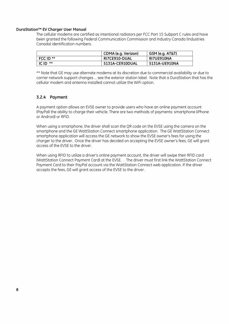
3.1.2 QR Code The DuraStation has a ¾” x ¾” Quick Response (QR) code label near the display and RFID reader. Each QR code holds a unique serial number in its image. The QR code is mapped to the station serial number in the GE WattStation Connect™ system. An EV driver or EVSE owner can use their iPhone and the GE DuraStation application to scan the QR code. Once the QR code is captured, the application will automatically connect to the GE WattStation Connect and provide the driver or EVSE owner with access and information for the DuraStation.
Figure 3.3
WARNING: Denotes operating procedures and practices that may result in personal injury or loss of life if not correctly followed
CAUTION: Denotes operating procedures and practices that, If not strictly observed, may result in damage to, or destruction of equipment.
NOTE: Notes call attention to information that is especially significant in understanding and operating the equipment.

DuraStation™ EV Charger User Manual
7
3.2 Communication OptionsThe DuraStation (Networked models only) has different options of network communication interfaces to the customer: Cellular, integrated WiFi module, or CAT5
3.2.1 Integrated Ethernet communications port TCP/IP communication over an IEEE 802.3 (a.k.a. “Ethernet”) compliant network between the EVSE and customer network is available in all EVSE models. A single CAT5e or better cable can be run from each EVSE to a network hub, router or switch in a star configuration.
DuraStation Ethernet ports support only 10BASE-T (10 Mbit/s) or 100BASE-TX (100 Mbit/s) network speeds. Installation on networks running at 1000BASE-T (100 Mbit/s) will require that the networks be configured to support devices that operate at 100 Mbit/s. The maximum length of the communication cables is determined by the CAT5e standard, which stipulates a maximum length of 100 m (328 feet). If longer runs are required, the use of active hardware such as a repeater or a switch is necessary.
3.2.2 Integrated WiFi Module option A DuraStation with WiFi communication incorporates a IEEE 802.11b/g compliant radio module. EVSE customers that do not select the WiFi communication option will not receive this radio module. The WiFi module allows the EVSE owner to communicate to GE WattStation Connect over WiFi. The WiFi module will have a connection to attach to the EVSE’s WiFi antenna. The WiFi module will support IEEE 802.11 b/g networks. Operation on IEEE 802.11n networks will therefore require that the networks be configured to support 802.11g devices. The WiFi module is disabled when shipped and is enabled by first connecting to the configuration tool via a CAT5 connection. The IEEE 802.11b/g compliant WiFi radio is certified as an intentional radiator per FCC Part 15 Subpart C rules and has been granted the following Federal Communication Commission and Industry Canada (Industrie Canada) identification numbers.
** Note FCC and IC radio IDs may change due to commercial availability … check the station label. Note that a station that has the WiFi radio and antenna installed cannot utilize the cellular option.
3.2.3 Cellular modem option The cellular modem will provide wireless communication for a single EVSE over a cellular provider’s network.
Due to the fact that cellular carrier technology and coverage is a dynamic situation, GE may offer DuraStations with a variety of cellular radios & carriers (CDMA/EV-DO, GSM/HSPA, LTE, etc.) over time. All cellular performance claims are based on the US coverage maps provided by the carriers. GE reserves the right to change cellular modem types and carriers at its discretion.
GE recommends that customers perform a site survey with a third party to ensure adequate cellular performance. The exact environmental factors of the location and orientation to the nearest cell tower strongly affect cellular performance.
FCC ID ** U9R-W2CBW009DI IC ID ** 7089-W2CBW09D
DuraStation™ EV Charger User Manual
8
The cellular modems are certified as intentional radiators per FCC Part 15 Subpart C rules and have been granted the following Federal Communication Commission and Industry Canada (Industries Canada) identification numbers.
** Note that GE may use alternate modems at its discretion due to commercial availability or due to carrier network support changes … see the exterior station label. Note that a DuraStation that has the cellular modem and antenna installed cannot utilize the WiFi option.
3.2.4 Payment
A payment option allows an EVSE owner to provide users who have an online payment account (PayPal) the ability to charge their vehicle. There are two methods of payments: smartphone (iPhone or Android) or RFID. When using a smartphone, the driver shall scan the QR code on the EVSE using the camera on the smartphone and the GE WattStation Connect smartphone application. The GE WattStation Connect smartphone application will access the GE network to show the EVSE owner’s fees for using the charger to the driver. Once the driver has decided on accepting the EVSE owner’s fees, GE will grant access of the EVSE to the driver. When using RFID to utilize a driver’s online payment account, the driver will swipe their RFID card (WattStation Connect Payment Card) at the EVSE. . The driver must first link the WattStation Connect Payment Card to their PayPal account via the WattStation Connect web application. If the driver accepts the fees, GE will grant access of the EVSE to the driver.
CDMA (e.g. Verizon) GSM (e.g. AT&T) FCC ID ** RI7CE910-DUAL RI7UE910NA IC ID ** 5131A-CE910DUAL 5131A-UE910NA

DuraStation™ EV Charger User Manual
9
3.3 Electronics
The Electronics Control Unit in the DuraStation integrates Control Pilot Functions, Metering, Overload monitoring, ground fault protection and all local monitoring.
3.3.1 Supplemental overload Protection The controller will open the main power switches at approximately 120% of nominal current.
3.3.2 Ground Fault protection DuraStation includes 15 - 20 mA GF protection per UL 2231. The EVSE provides fault indication if a ground fault has occurred. The fault will automatically reset per UL 2231 if the fault has occurred after charging has begun. This reset will occur after 15 minutes. Only 4 automatic retries can occur in a charging session. Unplugging the EVSE connector from the vehicle will close out a charging session and reset the number of automatic retries. If the ground fault is detected immediately after charging, the EVSE will stop charging and indicate a fault.
3.3.3 Ground Monitor Interrupter This feature is not included in DuraStation.
3.3.4 Ventilation Fault If a vehicle requests facility ventilation by taking the control Pilot to State D as defined by SAE J1772, the DuraStation will not charge the vehicle and issue a fault indication on the LED Ring and fault icon. The fault will be cleared once the EVSE connector is removed from the vehicle. State D charging can be enabled by configuration … check the box next to “Allow vehicles requiring ventilation to charge” on the COMMON page of the configuration tool (Networked models only).
3.3.5 Metering DuraStation measures the voltage, current, power and Energy consumed by the EV during a charge and the measured data is available through WattStation Connect (Networked models only). For all models, charging current and energy consumed are shown on the stations VFD display during the charge and after charging completes prior to vehicle disconnect.
3.3.6 RFID (Networked models only) The RFID reader will scan RFID cards and pass the scanned information to WattStation Connect for user authorization.
The RFID reader is certified as an intentional radiator per FCC Part 15 Subpart C rules and has been granted the following Federal Communication Commission and Industry Canada (Industrie Canada) identification numbers.
** Note: due to technology changes and commercial availability, GE reserves the right to change RFID readers … in such case check the exterior station label for the actual FCC and IC identifiers that are actually used in the station.
FCC ID ** JQ6-MCLASS15RP15E
IC ID ** 2236B-MCLASS15RP15E

DuraStation™ EV Charger User Manual
10
3.4 GE WattStation Connect (Networked models only)
GE WattStation Connect is a server application that allows owners to configure and monitor their EVSEs remotely. GE WattStation Connect also handles RFID authentication and setup. The customer will access GE WattStation Connect through their web browser on their PC
3.4.1 Status GE WattStation Connect will provide EVSE status to customers. The customer will receive these updates through their web browser, text message and/or email. Here is a list of status updates the customer will receive:
• Algorithm Status • History/Reporting • Actual current draw by each group member
- Summary of current draw for the entire group - Max current renegotiated - Algorithm settings committed - Algorithm enabled/disabled - Internal EVSE temperature
• Monitoring - EVSE state: disconnected, connected, charging and fault - Internal EVSE temperature
• Control - Scheduled charging - Override of charging - Charging delay
• Diagnostics - Ground fault - Loss communication - RFID failure - Un-authorized users - Contactor monitor - Overload - Over/Under voltage - Invalid payment - Additional fault diagnostics
3.4.2 Firmware Updates
The firmware for GE’s EV charging stations that are connected to GE WattStation Connect may be upgraded remotely by GE at any time to address critical bug fixes, security patches, or to add feature upgrades.

DuraStation™ EV Charger User Manual
11
3.5 Technical Details
Requirement Spec SAE Compliant Level 1 or Level 2 per SAE J1772 Vehicle Interface SAE J1772 EV connector Cable Length 22 feet AC Charging Power Output** 7.2kW (240VAC @ 30A) Voltage and Current Rating 120/208-240VAC @ 30A
AC Power Input 120/208-240VAC requiring only Line 1, Line 2, and Earth ground
Short Circuit Rating 5kA @ 240VAC
Recommended Service Panel Breaker
Pole, Wall, Single Pedestal: 2-pole 40A breaker on dedicated circuit Double Pedestal: (Qty. 2) 2-pole 40A breaker on dedicated circuit
Ground Fault Protection Internal 20mA CCID w/ auto re-closure, does not require a GFCI in service panel
Communication Option CAT5 Ethernet, WiFi or Cellular Metering Accuracy 2% accurate on voltage and current (higher accuracy option) RFID Reader HID MultiClass SE (model RP15EKNR) Display Screen Vacuum Fluorescent Display Standby Power 5W typ. (single), 10W typ. (dual) Outdoor Rated NEMA 3R
Safety Compliance (ETL Listing) UL 2231, UL 2251, UL 2594, cUL 2231, cUL 2594, NEC 625, SAE J1772
Surge Protection 6kV @ 3,000A EMI Compliance FCC Part 15 Class B Operating Temperature -30°C to +50°C ambient Operating Humidity Up to 95% non-condensing
Approximate Shipping Weights
Single Pedestal: 140 lbs Double Pedestal: 175 lbs Pole: 75 lbs Wall: 75 lbs
Dimensions
Single Pedestal: 51.1"H x 14.9"W x 13.8"D Double Pedestal: 51.1"H x 14.9"W x 13.8"D Pole: 31.52"H x 11.82"W x 11.16"D Wall: 31.52"H x 11.82"W x 11.16"D
Table – 3.2
**The maximum power consumption is determined by EVSE. The actual power consumption is determined by EV.

DuraStation™ EV Charger User Manual
12
4 Operation
4.1 Basic Operational Overview
• The LED bar on the EVSE DuraStation pedestal unit will glow green when the unit is not in use and not in a faulted or reserved condition.
• Before plugging the charging connector into the car, swipe the RFID card (if enabled) to initiate the
charge process. The VFD display will indicate whether or not the RFID is approved or denied.
• Plug the connector into car. The LED ring will start flashing green until the vehicle is ready for charge. This is usually a brief period of time. Some vehicles may have a delayed charge mode. In this case the vehicle may briefly ask for charge to see the voltage and current that is available, then go back into the paused state until it is ready for charge.
• Once the car initiates charging, the LED bar on the unit will change to amber and the VFD display
will show the current and energy that are being delivered.
• The LED bar on the unit will change from amber to flashing green once the car is fully charged, and the VFD display will show a summary of the charge (total energy delivered and connect time).
• When the vehicle is disconnected the LED bar on the unit will change from flashing green to solid
green.
• The LED bar will turn red if any faults occur and a fault code will indicate on the VFD display. Refer to Section 8 for fault codes and troubleshooting details.
4.2 Configuration (Networked Units only)
4.2.1 Connecting to Configuration Tool
The DuraStation Pedestal contains a configuration tool which can be used to establish owner preferences and to setup the communication parameters for the customer’s network. The initial connection to the Configuration Tool must be made via the Integrated Ethernet Communications port (see Section 3.2.1). Subsequent connections to the tool can be made over WiFi after the wireless network settings have been made to connect to the appropriate network. The default IP address for the DuraStation’s Ethernet communications port is 192.168.13.1. For the purposes of customer convenience, the DuraStation is shipped from the factory with default network setting of “DHCP enabled”. This means that the DuraStation will try to obtain an IP address from a DCHP server if one is available. IMPORTANT!
On double pedestal DuraStations changes made to the configuration tool are common between ports 1 and ports 2.

DuraStation™ EV Charger User Manual
13 GE Industrial Solutions ©2016 GE Company All Rights Reserved
If the DuraStation is not connected to a network with a DHCP server then it will default to an IP address of 192.168.13.1. Before connecting to the tool, ensure your computer has an IP address on the same subnet as the DuraStation. The method to do this varies by operating system. Pull up a menu that lets you modify the Local Area Connection properties (see below). On Windows machines this is done through the Control Panel, then selecting Network, then selecting Adapter settings. Then right click on Local Area Connection and select Properties.
The next step is to select IPv4 and click properties (on some older operating systems that don’t support IPv6 this might just be TCP/IP settings or something similar). Uncheck “Obtain an IP address automatically” and instead assign a static IP address on the same subnet as the DuraStation and subnet mask as shown below.
Figure – 4.1 Figure – 4.2
After saving settings reboot the computer or otherwise verify that its IP settings have changed. Connect the computer’s Ethernet port to the DuraStation’s single-board computer RJ45 connector with a CAT5 cable. Connection to the configuration tool can now be made by typing the following into the browser’s URL window.
Type into URL window: https://192.168.13.1
The web browser will likely respond with a screen questioning the security of the DuraStation’s https server. This is fine and to be expected (see Section 4.2.2 – Accepting Connection to the Configuration Tool).

DuraStation™ EV Charger User Manual
14 GE Industrial Solutions ©2016 GE Company All Rights Reserved
4.2.2 Accepting Connection to the Configuration Tool
The DuraStation configuration tool runs over a secure http server that uses a so-called self-signed digital certificate that was created by GE Industrial Solutions specifically for the DuraStation. Since this certificate was not issued by a trusted SSL certificate provider (e.g. VeriSign or GoDaddy.com), the browser will issue an alert or warning questioning the trustworthiness of the certificate before loading the page.
Alert screen from Microsoft Internet Explorer Alert screen from Mozilla Firefox Click “Continue to this website” Click “I Understand the Risks” Figure – 4.3 Figure – 4.4
Alert screen from Apple Safari Alert screen from Click “Proceed anyway” Click “Continue” Figure – 4.5 Figure – 4.6
After continuing as directed above, the browser window may have some kind of visible indication that the HTTPS connection is made with an untrusted certificate. For example, in Internet Explorer the URL window is shaded in red (see below).
DuraStation™ EV Charger User Manual
15 GE Industrial Solutions ©2016 GE Company All Rights Reserved
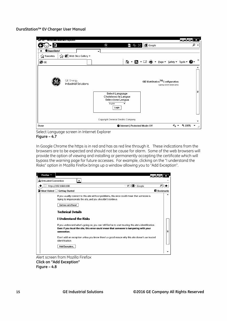
Select Language screen in Internet Explorer Figure – 4.7
In Google Chrome the https is in red and has as red line through it. These indications from the browsers are to be expected and should not be cause for alarm. Some of the web browsers will provide the option of viewing and installing or permanently accepting the certificate which will bypass the warning page for future accesses. For example, clicking on the “I understand the Risks” option in Mozilla Firefox brings up a window allowing you to “Add Exception”.
Alert screen from Mozilla Firefox Click on “Add Exception” Figure – 4.8

DuraStation™ EV Charger User Manual
16 GE Industrial Solutions ©2016 GE Company All Rights Reserved
Add Security Exception window in Mozilla Firefox Click on “Confirm Security Exception” Figure – 4.9
Following these steps will allow you to bypass the security alert page for future accesses to the configuration tool.
4.2.3 Using the Configuration Tool
From this point forward there is no difference between the browsers. The initial login screen will appear as follows. First select your language of choice.
Select Language screen in Configuration tool Figure – 4.10

DuraStation™ EV Charger User Manual
17 GE Industrial Solutions ©2016 GE Company All Rights Reserved
On the Login screen enter the User Name and Password provided on the Provisioning or Commissioning card that was provided with your DuraStation. You may wish to write these into the boxes below in case your card ever gets lost or separated from this instruction manual.
Login screen in Configuration tool Figure – 4.11 After logging in, you will be taken to the Home screen which appears as follows:
Home screen in Configuration tool Figure – 4.12

DuraStation™ EV Charger User Manual
18 GE Industrial Solutions ©2016 GE Company All Rights Reserved
From this screen you can select from one of the following options.
• Configuration settings tab: o Common …………….. a variety of settings to configure DuraStation functionality o Authorization ……… settings to configure access control and payment options o GE Connect ….… settings to configure your DuraStation location and time zone o Modbus ……………….. settings to configure Modbus (may not be available on
DuraStation) o Networking ………… settings to configure networking and WiFi security options
• Diagnostics tab:
o Troubleshooting information (e.g. fault codes) which are also described in Section 8 of this manual.
• Factory Defaults tab: o This tab provides for the option of restoring the configuration settings back to
their factory default settings.
• Device Info tab: o Shows summary of all configuration settings.
• Network Troubleshooting tab:
o Provides a number of diagnostic commands useful for network setup and for diagnostics of wired and wireless network problems:
� ifconfig – information such as IP address and MAC address for each port � iwlist – scans for available WiFi signals and displays results � ping – can be used to test connection to other IP addresses � route – shows the contents of the routing tables
• Logout tab:
o Don’t forget to logout before exiting your browser as the configuration tool restricts usage to one logged in user at a time. If you try to login and get a message that someone else is currently logged in and if you are certain that the last user just forgot to logout, simply wait one minute and then try to login again.
IMPORTANT!
For configuration changes to take effect, the changes must be saved to the configuration file.
This happens on a page by page basis when the submit button is pressed.

DuraStation™ EV Charger User Manual
19 GE Industrial Solutions ©2016 GE Company All Rights Reserved
4.2.4 Common Settings tab
The configuration tool provides built-in help text which is accessed simply by hovering your mouse over the feature. For example, help for “Enable LED Ring Dark Mode” is shown below.
Common screen under Configurations tab Figure – 4.13
Note: The Allow Simplified Control Pilot and Enable Diode Test settings affect the requirements of contactor turning on, therefore GE recommends either checking neither or checking both. Features are subject to change as new firmware is released so picture is shown as example. Note that some features are specific to certain models, e.g. LED ring color brightness settings are applicable to the WattStation pedestal station only.

DuraStation™ EV Charger User Manual
20 GE Industrial Solutions ©2016 GE Company All Rights Reserved
Description of other settings on this page:
• Enable LED Ring Dark Mode
Turns the light bar off … turns on for 1 second when it is changing state.
• Allow vehicles requiring ventilation to charge The IEC 61851 and SAE J1772 standards allow for vehicles (which are no longer common) which have batteries which may outgas during charging. Setting this option will allow these types of EVs to charge, so this should only be allowed for outdoor installations or indoor installations when it can be verified that adequate ventilation is present.
• Rated Current for Installation (Amps)
The DuraStation Pedestal is rated for 30 Amps but there may be some installations in which DuraStation owners want to restrict charging to lower currents. This option sets the maximum current that the vehicle can draw per SAE J1772.
• Start Charging Delay after Power-up
If a car is connected and authorized and power is lost, when power is restored it will start charging again automatically. This setting inserts a random delay from 0 to the value selected in the start-up time after power is restored. A setting of 0 means no delay.
• Station, Group and Locality IDs
Optional settings that can be used to identify stations, e.g. station can be labeled as Station #4 in Group 3 in Locality 1, where Group is parking facility #3 in city of New York.
4.2.5 Authorization Options
The DuraStation Pedestal can be configured for any of three (3) Authorization Modes, which are:
Mode VFD message displayed Authorization
Required Payment Required
Free Access “Please Connect Vehicle to Begin” Unchecked Unchecked RFID Access “Please Swipe RFID to Authorize” Checked Unchecked
Payment “Use RFID or Mobile App to Pay” Checked Checked Note: the text shown in quotes appears on the stations VFD display. IMPORTANT!
With the exception of Free Access mode, DuraStation owners must use their WattStation Connect accounts to select how RFID Access mode and/or Payment modes are enabled. For example, RFID card enrollment, payment set-up, etc. must be performed on the owner’s WattStation Connect account.
Note that there is a convenient method of using the stations to enroll RFID cards. There is an option on the WattStation Connect owner’s account to put a station into “enrollment mode”. When a station is put into enrollment mode any card that is swiped at that station will be enrolled for all stations in that station’s group.
These station configuration settings are there to so that the VFD display will properly
communicate to the operator of the station what authorization mode is required.

DuraStation™ EV Charger User Manual
21 GE Industrial Solutions ©2016 GE Company All Rights Reserved
Authorization screen under Configurations tab Figure – 4.14 The other authorization options in this tab are:
• Access Limit Enables limiting charge time or energy based on data provided by GE backend … this may a future feature provided by the GE WattStation Connect service.
• Swipe RFID to Release Cable … this option is for IEC type of units only with detachable cords
• Allow RFID authorization when network down (** see note) This option gives DuraStation owners the ability to make the RFID enabled DuraStations available for use during times of network outages. If no response is received the authorization will be granted until or less an authorization denied response is received from the back-end.
• Enable Local RFID authorization (** see note)
This feature will only be available when GE WattStation Connect cloud service offers it. This option theoretically gives station owners the ability to make their stations utilize a local database of cards which has been downloaded from the GE WattStation Connect. The database can also be built up over time as cards are used and added to the local database. When a card is used for the first time, the GE WattStation Connect will reply back not only whether the card is authorized or not, but for how long it is authorized. That information goes into the local database. Checking this option makes the authorization immediate when the card is enabled per the local database.
** “RFID Test mode” … Checking both “Allow RFID authorization when network down” and “Enable Local RFID authorization” allows the station to be put into an RFID test mode which can be used as a poor man’s access control when network connectivity is not available. The station will require authorization but will immediately grant access when any readable RFID card is swiped.
DuraStation™ EV Charger User Manual
22 GE Industrial Solutions ©2016 GE Company All Rights Reserved
4.2.6 GE WattStation Connect Options
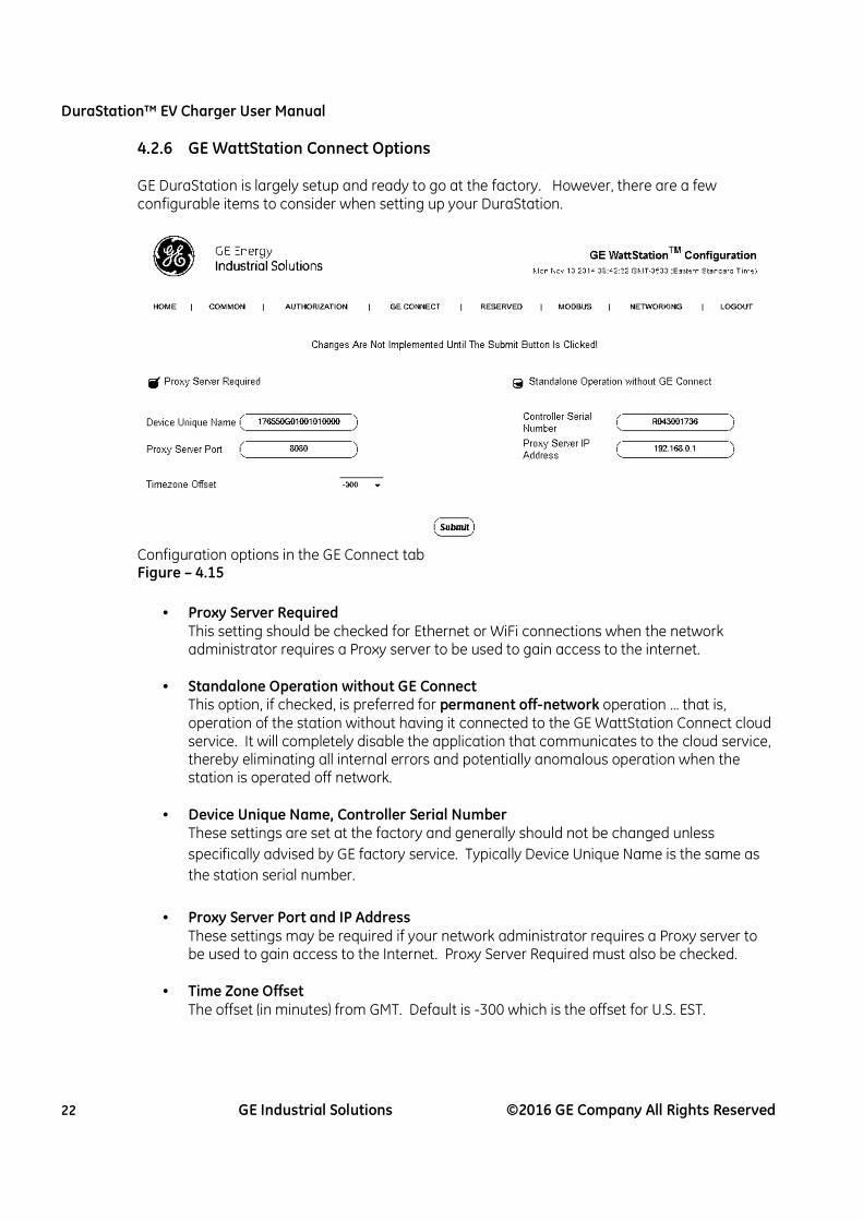
GE DuraStation is largely setup and ready to go at the factory. However, there are a few configurable items to consider when setting up your DuraStation.
Configuration options in the GE Connect tab Figure – 4.15
• Proxy Server Required This setting should be checked for Ethernet or WiFi connections when the network administrator requires a Proxy server to be used to gain access to the internet.
• Standalone Operation without GE Connect This option, if checked, is preferred for permanent off-network operation … that is, operation of the station without having it connected to the GE WattStation Connect cloud service. It will completely disable the application that communicates to the cloud service, thereby eliminating all internal errors and potentially anomalous operation when the station is operated off network.
• Device Unique Name, Controller Serial Number
These settings are set at the factory and generally should not be changed unless
specifically advised by GE factory service. Typically Device Unique Name is the same as
the station serial number.
• Proxy Server Port and IP Address These settings may be required if your network administrator requires a Proxy server to be used to gain access to the Internet. Proxy Server Required must also be checked.
• Time Zone Offset
The offset (in minutes) from GMT. Default is -300 which is the offset for U.S. EST.

DuraStation™ EV Charger User Manual
23 GE Industrial Solutions ©2016 GE Company All Rights Reserved
4.2.7 Network Settings
This tab is used to configure the network settings of the DuraStation.
Configuration Options in the Networking tab Figure – 4.17 Important Note! Cellular equipped stations will exchange the WiFi setting options with some cellular settings as shown above. These settings are pre-set at the factory and should not be changed unless customer wants to operate the station by Ethernet instead. In such case simply uncheck “Enable Cell modem” and set “Network Interface to GE CONNECT” = eth0. Be sure to hit submit after making changes, noting that some setting changes could possibly change the IP address thereby terminate the connection to the configuration tool.

DuraStation™ EV Charger User Manual
24 GE Industrial Solutions ©2016 GE Company All Rights Reserved
• Enabling Networks and DHCP
Note that the wired Ethernet port cannot be disabled. Dynamic Host Control Protocol (DHCP) tells the DuraStation to get IP addresses from DHCP servers if available. For DuraStations with a top-mounted antenna, either “Enable WiFi” or “Enable cellular” will be possible. If WiFi or Cellular connectivity is desired for the GE back-end connection, be sure that “Network Interface to GE CONNECT” is set to eth1 (WiFi) or ppp0 (cellular).
• Static IP settings, subnet masks and gateway IPs
These settings are used if DCHP functionality is disabled … if DHCP is enabled they are the
fallback settings used if a DHCP server does not reply.
• Primary and Alternate DNS
These are defaulted to the popular Google DNS servers, but can be changed as desired.
• Routing Table settings This is advance functionality for network specialists. These settings are used to add or
delete entries to the routing table as follows: o Routing Network/Host IP address. Traffic to this IP address is routed via the Routing Gateway.
o Routing Netmask. Subnet to use for the Network/Host.
o Routing Gateway. Routing Gateway to be used for the Network/Host.
o Routing Table choices: No Action, Add, Delete
o Routing Interface choices: eth0, eth1 for wired or wireless table entry, respectively
Tables for either the wired or wireless port can be built by entering the host and gateway
IP addresses and subnet mask, and by selecting Add and the appropriate port. The
routing tables can be viewed by going to the Home screen and then clicking on Network
TS (Trouble-Shooting).
• WiFi Network Name
In order to use WiFi you must not only enable it but you must enter a WiFi network name, also known as SSID. Alpha/numeric characters are ok, but no spaces are allowed in the SSID name.
• WiFi Security, WEP keys, WPA(2)-PSK passphrase
These common WiFi security options are supported: o None. This is open, unsecured WiFi. It is available for ease of installation and debugging but it
is not recommended that you operate the station over open and unsecured WiFi.
o WEP 64-bit. This setting requires entry of a 10 digit hexadecimal key. Hexadecimal digits are
0–9 and A–F.
o WEP 128-bit. This setting requires entry of a 26 digit hexadecimal key.
o WPA-PSK (TKIP). This setting is more secure than WPA and uses TKIP encryption. It requires
entry of an 8 to 63 character passphrase.
o WPA2-PSK (AES). This setting is the most secure and uses AES encryption. It also requires
entry of an 8 to 63 character passphrase. Some routers set to WPA2 encryption do not
respond fast enough for DHCP clients to avoid taking an IP address from the autoIP range. If
this happens, try reserving an IP address in your router if it supports this feature, or use static
addressing, or use another encryption mode.

DuraStation™ EV Charger User Manual
25 GE Industrial Solutions ©2016 GE Company All Rights Reserved
4.3 Configuration (Non-Networked Units only)
4.3.1 Installation of Optional De-Rate Jumper J21 This section illustrates how to configure Non-Networked DuraStations to deliver less than the full 30A that stations are designed to deliver. The stations will automatically adjust for line voltage, but if installed on less than 40A branch circuits the J21 jumper should be installed so that the station will not overload the circuit and cause the circuit breaker to trip.
for 40A Circuit … normal 208/240Vac installation) … do not install jumper Jumper J21 shown as delivered with wire connected only to position 1. The DuraStation by default will provide a duty cycle to the car indicating that 30A may be drawn. The jumper should not be installed when installing the DuraStation on a 40A branch circuit.
for 15A Circuit … normal 120Vac installation Optional position A … connect other end of wire to position #2 and the DuraStation will provide a duty cycle to the car indicating that only 12A may be drawn. This position should be used when installing the DuraStation on a 15A branch circuit.
for 20A Circuit … optional installation for either 120Vac or 208/240Vac Optional position B … connect other end of wire to position #3 and the DuraStation will provide a duty cycle to the car indicating that only 16A may be drawn. This position should be used when installing the DuraStation on a 20A branch circuit.

DuraStation™ EV Charger User Manual
26 GE Industrial Solutions ©2016 GE Company All Rights Reserved
for 30A Circuit … optional installation for 208/240 Vac Optional position C … connect other end of wire to position #4 and the DuraStation will provide a duty cycle to the car indicating that only 24A may be drawn. This position should be used when installing the DuraStation on a 30A branch circuit.
Optional position D … connect other end of wire to position #5 and the DuraStation will disable the vehicle pilot diode check (see fault code 134), but will not allow simplified charging (see fault code 154). It is possible to disable the diode test with a de-rated current by installing a special jumper, e.g. to disable the diode test and operate at 16A the jumper would need to connect pins 1, 3 and 5 … contact GE if a special jumper is needed (1-855-4GE-EVSE).
5 Networking (Networked units only)
5.1 Overview
The GE DuraStation utilizes network LAN and Internet technologies to connect charging units to GE’s dedicated EVSE environment. This environment allows for monitoring, billing, and other future services from a central location. This service does require a dedicated connection to the Internet. Depending on how your DuraStation was configured at the factory the following connectivity options are available.
• Dedicated Cellular modem – Utilizing cellular technology this option offers a dedicated connection to the Internet. The modem is on-board the single board computer (SBC) in the DuraStation unit and is not user serviceable.
• Ethernet Port – This option allows for the use of an existing Internet connection. The LAN interface on the DuraStation supports speeds of 10/100 megabit capability.
• WiFi – WiFi is also an option for connecting the DuraStation to an existing wireless environment. The WiFi interface is compatible with 802.11 b/g 2.4Ghz WiFi networks.
5.2 Terms & Definitions
It is important to understand terms used throughout this section.

DuraStation™ EV Charger User Manual
27 GE Industrial Solutions ©2016 GE Company All Rights Reserved
LAN – Local Area Network – A local area network (LAN) is a group of computers and associated devices that share a common communications line or wireless link. Ethernet – The most common LAN connectivity method. This is a physical wired technology that consists of the use of twisted pair wiring. WiFi or WLAN – This is a mechanism that allows an electronic device to exchange data wirelessly over a computer network. Cellular modem – This is a device that uses wireless cell technology to connect to a network instead of to the telephone system. Firewall – A firewall is a device or set of devices designed to permit or deny network transmissions based upon a set of rules and is frequently used to protect networks from unauthorized access while permitting legitimate communications to pass. Proxy Server – In computer networks, a proxy server is a server (a computer system or an application) that acts as an intermediary for requests from clients seeking resources from other servers. LAN Switch – A network device that cross-connects clients, servers and network devices. LAN Router – This is a network device that forwards packets from one network to another. LAN Speeds – The most common Ethernet speeds are 100 megabit (Fast Ethernet) and 1000 megabit (Gigabit Ethernet). This is how fast information moves across a LAN. LAN Port – This can be either a wall jack or a physical port on a LAN switch.
Cat5 – This is a twisted pair cable standard for carrying signals. This cabling is used for Ethernet and other networks. Maximum Ethernet Cat5 cable distance is 100 meters or 328ft. VLAN or Virtual LAN – This is a group of hosts with a common set of requirements that communicate as if they were attached to the same broadcast domain, regardless of their physical location. A VLAN has the same attributes as a physical local area network (LAN), but it allows for end stations to be grouped together even if they are not located on the same network switch. VLAN membership can be configured through software instead or by physically relocating devices or connections. IP Address – An Internet Protocol address (IP address) is a numerical label assigned to each device (e.g., computer, printer) participating in a computer network that uses the Internet Protocol for communication. Subnet Mask – The subnet mask determines how the IP address is divided into network and host parts. Default Gateway or LAN Gateway – A node on a TCP/IP network that serves as an access point to another network. A default gateway is the node on the computer network that network software uses when an IP address does not match any other routes in the routing table. DHCP – DHCP (Dynamic Host Configuration Protocol) is a communications protocol that lets administrators centrally manage and automate the assignment of Internet Protocol (IP) addresses in a network.
DuraStation™ EV Charger User Manual
28 GE Industrial Solutions ©2016 GE Company All Rights Reserved
DNS – Domain Name Server – A DNS server translates Internet domain and host names to IP addresses. Internet Port – Every service that you connect to on the Internet listens on a particular port. For example the World Wide Web Service listens on port 80. Whenever you go to a website, your browser is actually connecting to a particular computer on its port 80. Other services use other ports. Topology – In a network LAN the topology is the structure of nodes and how they connect to one another. Static IP Route – A static IP route is way or directing network traffic through a specific path or gateway. In order to reach other networks it is sometimes necessary to configure specific routes to override the default gateway path. BMS – Building Management System – This is a computer-based control system installed in buildings that controls and monitors the building’s mechanical and electrical equipment such as ventilation, lighting, power systems, fire systems, and security systems.

DuraStation™ EV Charger User Manual
29 GE Industrial Solutions ©2016 GE Company All Rights Reserved
5.3 Network Topologies
There are many different network topologies that the GE DuraStation supports. This includes wired Ethernet, WiFi and a dedicated Cellular modem. It is important to understand the following minimum requirements for all topologies.
- Internet connection … either Ethernet, WiFi or cellular - LAN switch or WiFi Access Point - DHCP server or a Static IP Address - Wired Ethernet – Cat5 or better wiring - WiFi Access Point that supports 802.11 b/g WiFi speeds
Please note that the pictorials shown below are of the WattStation™ Wallmount. Note that dual charge port stations only have one single board computer thus only 1 cable needs to be run, so from a networking perspective DuraStations™ are the same.
Topology #1: Ethernet In this configuration each DuraStation is connected to a common Ethernet LAN to provide primary connectivity. The DuraStations do not need to be plugged into the same switch, but the switches must be part of the same common network segment or VLAN. Internet connectivity is provided through the default gateway.
Topology #2: WiFi In this configuration the unit’s WiFi port is used to provide primary connectivity. The security settings for the WiFi must be manually configured in the DuraStation before connectivity can take place.
DuraStation™ EV Charger User Manual
30 GE Industrial Solutions ©2016 GE Company All Rights Reserved
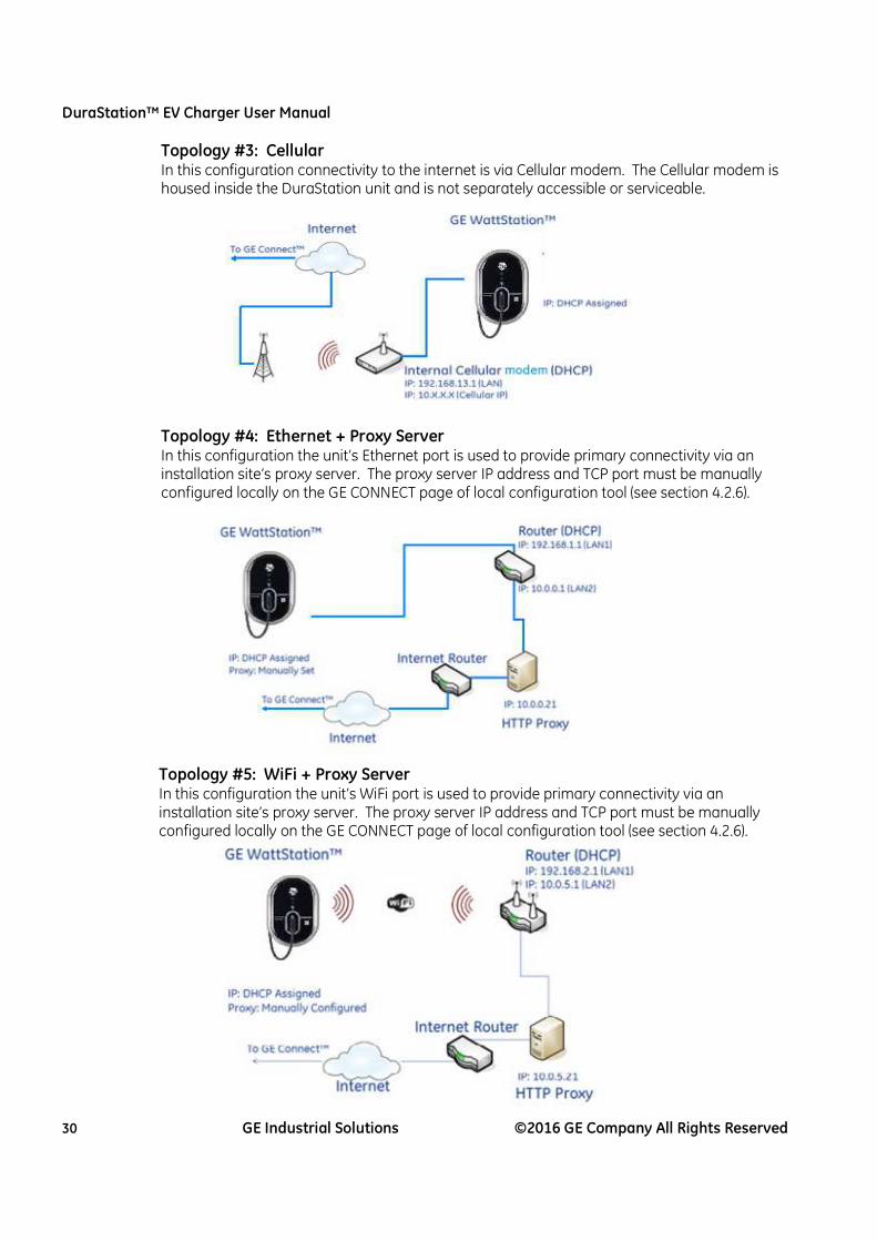
Topology #3: Cellular In this configuration connectivity to the internet is via Cellular modem. The Cellular modem is housed inside the DuraStation unit and is not separately accessible or serviceable.
Topology #4: Ethernet + Proxy Server In this configuration the unit’s Ethernet port is used to provide primary connectivity via an installation site’s proxy server. The proxy server IP address and TCP port must be manually configured locally on the GE CONNECT page of local configuration tool (see section 4.2.6).
Topology #5: WiFi + Proxy Server In this configuration the unit’s WiFi port is used to provide primary connectivity via an installation site’s proxy server. The proxy server IP address and TCP port must be manually configured locally on the GE CONNECT page of local configuration tool (see section 4.2.6).

DuraStation™ EV Charger User Manual
31 GE Industrial Solutions ©2016 GE Company All Rights Reserved
5.4 Firewall and security considerations
5.4.1 Firewalls
The GE DuraStation uses standard Internet HTTP & HTTPS protocols to connect to GE’s dedicated environment. Some locations may utilize firewalls or similar filtering devices to secure their environment. The following table lists IP addresses and ports that must be allowed for the GE DuraStation to communicate properly. The DNS names are provided as reference and firewall or filtering device will most likely only use the IP address and TCP port numbers. If possible it is recommended to open the entire 165.156.12.xx subnet.
DNS Domain Name IP Address Internet Port
bemp.gewattstation.com 165.156.12.31 TCP Ports 80 & 243
services.gewattstation.com 165.156.12.37 TCP Ports 80 & 243
Table – 4.2
5.4.2 Proxy Servers
It is recommended to use a direct Internet connection when possible. If your environment does not have this capability you may need to use your installation site’s proxy server. You will need to obtain the proxy server DNS name and TCP port that it operates on. This proxy information will need to be entered into the GE CONNECT tab of the configuration tool. Many sites that utilize proxy servers for Internet access also require the use of a login or other information to gain access to the Internet. For the DuraStation unit to work properly there may be a requirement for your IT team to exclude the gewattstation.com Internet domain from requiring authentication.

DuraStation™ EV Charger User Manual
32 GE Industrial Solutions ©2016 GE Company All Rights Reserved
6 Kits
6.1 Pedestal Assembly Catalog Numbers
Description Connect Communication Catalog No. Single Pedestal w/ Connect Yes CAT 5 EVDPR3GEXXGB Single Pedestal w/ Connect Yes WiFi EVDPR3GWXXGB Single Pedestal w/ Connect Yes Cellular (CDMA) EVDPR3GZXXGB Single Pedestal w/ Connect Yes Cellular (GSM) EVDPR3GAXXGB Double Pedestal w/ Connect Yes CAT 5 EVDDR3GEXXGB Double Pedestal w/ Connect Yes WiFi EVDDR3GWXXGB Double Pedestal w/ Connect Yes Cellular (CDMA) EVDDR3GZXXGB Double Pedestal w/ Connect Yes Cellular (GSM) EVDDR3GAXXGB Pole Mount No None EVPN3 Wall Mount No None EVWN3 Single Pedestal No None EVSN3 Double Pedestal No None EVDN3
Table – 5.1

DuraStation™ EV Charger User Manual
33 GE Industrial Solutions ©2016 GE Company All Rights Reserved
6.2 Replacement kits The EV Charging Station offers the following replacement kits, Refer the respective Instruction sheets from the package for the installation of these kits.
Catalog # Description
EVDS2CBL01 GEN2 DS Charge Cable Replacement
EVDS2TB01 Terminal Block replacement
EVDS2TBHS01 Single DS Terminal Block Harness Replacement
EVDS2TBHS02 Double DS Terminal Block Harness Replacement
EVDS2TBHS03 Wall/Pole DS Terminal Block Harness Replacement
EVDS2MCT01 Metering CT Replacement Kit
EV40FUSE01 Fuses replacement kit
EVCAT5CBL CAT 5 Cable Replacement
EVDSPD02 Fuse Block Replacement/Protective devices
EVDSANT01 Networked DS Antenna Replacement
EVDSSBCW SBC-WIFI/Ethernet
EVDSSBCZ SBC-Cellular (CDMA)
EVDSCT01 CT's Replacement
EVDSDR02 Service Door Pedestal
EVDSLED01 LED Replacement - EVSE Pedestal
EVDSMAN01 Manual
EVDSMT01 Durastation Mounting Kit
EVDSRR02 Durastation RFID Kit
EVDSSK01 Socket Inlet Replacement Kit
EVDSVFD01 VFD Display Replacement Kit
EVDSRR01 RFID Replacement
EVDSDR01 Service Door - Wall Mount
EVDSMT02 Mounting Kit for Wall Mount
EVPMBAND Band-IT Tool to Cut Pole-Mount Metal
Table – 5.2

DuraStation™ EV Charger User Manual
34 GE Industrial Solutions ©2016 GE Company All Rights Reserved
7 Trouble-shooting
7.1 Fault Icon codes When the DuraStation™ controller experiences an alarm or fault it will display a fault code on the display. Alarms and faults are classified into three different categories:
Hard faults – These problems are generally considered to be caused by an issue within the station, therefore the AC power must be cycled in order to clear these faults. Soft faults – These problems are generally considered to be caused by an issue with the vehicle, therefore the vehicle must be disconnected in order to clear these faults. If not, explore potential problems within the station (e.g. ground fault caused by damaged charge cord or wiring problem with the station). Alarms – These codes can clear automatically if the condition causing the alarm goes away (e.g. undervoltage).
7.2 Hard Faults Code 111 – Pilot out of range at startup This fault indicates that the controller has measured an illegal voltage on the pilot interface during the power-up self-test sequence. Check the wiring and confirm that the pilot is correctly wired to connector J7. The pilot line should be connected to J7-1 and chassis ground to J7-2. Codes 112, 113 These faults are no longer used … should they occur please contact GE technical support.
Code 114 – Relays shorted or won’t open This fault can be set during power-up self-test if AC voltage is not detected on the relay output feedback input to the controller. The fault can also be set if the relays do not open when commanded by the controller to do so. Generally if this fault is persistent the charge controller (p/n 10106261G25) will need to be replaced. Code 115 – Controller Non-Volatile Memory (NVM) corrupt This fault would be set during the controller’s power-up self-test sequence, indicating that the non-volatile memory used to store charging state information was corrupt. If cycling power several times does not clear the fault, the charge control board will need to be replaced.
Code 121 – Temperature sensor reading out of range This fault would be set during the controller’s power-up self-test sequence, indicating that the on-board temperature sensor is defective. If cycling power several times does not clear the fault, the charge control board will need to be replaced. Code 122 – Invalid MAC address This fault would be set during the controller’s power-up self-test sequence, indicating that the Ethernet port on the charge control board has an invalid MAC address. If cycling power several times does not clear the fault, the charge control board will need to be replaced. Code 124 – Communication Controller Failure If cycling power several times does not clear the fault, the communication control board (a.k.a. SBC) will need to be replaced.
DuraStation™ EV Charger User Manual
35 GE Industrial Solutions ©2016 GE Company All Rights Reserved
Code 125 – Charge Controller fault This fault indicates that the charge control board is failing a self-test needed to insure it’s integrity at performing safety functions, such as RAM test or ROM test. If cycling power several times does not clear the fault, the charge control board will need to be replaced.
7.3 Soft Faults Code 131 – Ground Fault (GF) maximum retry per charge cycle exceeded This fault indicates that the controller has detected more than 4 ground faults in a charge cycle, meaning that the number of allowed retries has been exceeded. The charging plug must be removed from the electric vehicle (EV) socket in order to clear this fault. Code 132 – Ground Fault (GF) self-test failed The controller’s GF protection circuit is verified every time a vehicle is connected. This fault indicates that the self-test has failed. The charging plug must be removed from the EV socket in order to clear this fault. Note: The GF protection circuit is also verified during the controller’s power-up self-test sequence. If the GF self-test fails at this time, the fault will behave like a hard fault, and cycling AC power will be required to clear the fault. If the problem persists, verify that the GF CT (the CT with the black and white body) leads (red and black) are connected to J10 and the self-test wire loop leads (same color) are connected to J19. The polarity of these leads does not matter. Code 133 – Overcurrent trip The charge controller performs a secondary overload protection feature to prevent the internal fuses or upstream branch feeder breaker from tripping in the case of a defective vehicle. This fault indicates that the controller has detected an overcurrent condition and tripped. The charging plug must be removed from the EV socket in order to clear this fault. With power removed, the fuses should also be checked as some high level fault conditions are too fast for this secondary protection to prevent the fuses from blowing. Code 134 – Pilot diode test failed The SAE J1772 standard requires a diode to be present in the vehicle’s pilot circuit. Prior to every charge cycle, the charge controller checks for the presence of this diode, and if it is not there will issue this fault. The charging plug must be removed from the EV socket in order to clear this fault. It is possible to disable the pilot diode test using the local configuration tool (see section 4.2.4 for Networked models or section 5.3.1 for Non-Networked models). Note that GE recommends disabling simplified charging if the diode test is disabled. Code 135 – Relays won’t close Every time the charge controller attempts to close the relays that provide power to the EV, it checks immediately afterwards for feedback that the relays actually closed. If the feedback does not change state, this fault will be issued. The charging plug must be removed from the EV socket in order to clear this fault. Generally if this fault occurs repeatedly the charge controller (p/n 10106261G25) will need to be replaced, unless the fault is occurring in conjunction with fault 214 (see code 214 description). Code 142 – Fan required to charge The SAE J1772 standard has an accommodation for electric vehicles which have batteries that Potentially outgas during charging. These vehicles will take the pilot to State D (i.e. 3V) instead of the normal State C (6V) to indicate they are ready for charge. If used indoors, facility ventilation is required to charge these types of vehicles. It is possible to allow State D charging using the local configuration tool (see section 4.2.4). The charging plug must be removed from the EV socket in order to clear this fault.
DuraStation™ EV Charger User Manual
36 GE Industrial Solutions ©2016 GE Company All Rights Reserved
Codes 143, 144, 145, 151, 152 – Communication Controller Failure If the fault does not automatically clear or by removing the EVSE connector from the vehicle, cycle power on the WattStation.
7.4 Alarms Code 153 – Ground fault This alarm indicates that the charge controller has detected a ground fault condition that exceeds the allowable levels per UL 2231-2. The station implements the CCID 20 protection as defined in UL 2231- 2, which requires a 20mA ground fault to trip in under 1 second (higher currents require faster trip times). The controller will automatically reclose after a 15 minute delay, up to a maximum of four times per charging cycle. On the fifth ground fault, the controller will issue code 131 and the charging plug will have to be removed from the EV to clear the fault. Code 154 – Pilot transition violation This alarm indicates that the charge controller has detected a transition from State A (12V) to State C (6V) on the vehicle Pilot circuit input (J7). Unless it is specifically configured to allow the State A to State C transition (bypassing State B) by enabling Simplified charging in the local configuration tool (see Section 4.2.4 for Networked models or Section 5.3.1 for Non-Networked models), the charge controller will issue this alarm. The alarm will clear automatically when the Pilot is returned to State A. Code 155 – Pilot 0V feedback This alarm indicates that the charge controller has detected zero volts on the vehicle Pilot circuit input. The charge controller does not have the capability to take the pilot to 0V, therefore check for problems in the wiring to J7. If necessary measure the resistance of the pilot conductor (J7 pin 1) to chassis ground (J7 pin 2). Remember problems could be in the charge cord or on the vehicle side. This alarm will clear automatically when the short circuit condition is removed. Code 211 – Overvoltage This alarm indicates that the charge controller has detected AC line voltage in excess of 270 Vac. This alarm will only set when charging or trying to charge. It will not set during standby operation or when the vehicle is still connected after charging completed. When the overvoltage alarm sets, the alarm condition will persist for a minimum of one minute, after which time the alarm will clear when voltage drops to 265 Vac or below. Code 212 – Undervoltage This alarm indicates that the charge controller has detected AC line voltage below 170 Vac. This alarm will only set when charging or trying to charge. It will not set during standby operation or when the vehicle is still connected after charging completed. When the undervoltage alarm sets, the alarm condition will persist for a minimum of one minute, after which time the alarm will clear when voltage rises to 177 Vac or above. Code 214 – E-Stop input open This alarm indicates that that the E-stop input has opened … inspect J14 jumper on the control board. Code 215 – Charge Controller communication fault This alarm indicates that the charge controller is having trouble communicating with the communication controller (SBC). This should be a transient condition which should automatically Clear, if not, cycle AC power to clear. If persistent inspect the 4-pin cable connecting the charge controller J2 connector to the SBC CN1 (port 1) orCN2 (port 2) connector.

DuraStation™ EV Charger User Manual
37 GE Industrial Solutions ©2016 GE Company All Rights Reserved
DuraStation™ EV Charger User Manual
38 GE Industrial Solutions ©2016 GE Company All Rights Reserved
8 LIMITED WARRANTY FOR GE DuraStation (Pedestal) (“this Warranty”)WARRANTY
Any one or more of the following actions acknowledges that you have read and agree to the terms of this warranty agreement: Your use of the GE DuraStation
(Pedestal) packaged with this Instruction Manual (the
“Hardware”), online product registration of the Hardware, or your return of the enclosed Registration Card. GE’s warranty obligations for this Hardware product are limited to the terms set forth in this Limited
Warranty and are limited by and subject to the Exclusions and Limitations set out below. GE warrants that this Hardware product shall be free of defects in materials and workmanship under normal use for a period of three (3) years from the date of
manufacture (the “Warranty Period”). If a defect in the Hardware arises and a valid claim is received within the Warranty Period, your sole and exclusive remedy will be for GE, in its sole discretion and to the extent permitted by law, to (1) repair the defect in the Hardware at no charge, using new parts or refurbished
parts, or (2) exchange the Hardware with new or refurbished hardware that is functionally equivalent to the original Hardware, (the repaired Hardware and the exchanged hardware are called the “Remedied Hardware”). Any Remedied Hardware product will be warranted for the remainder of the original warranty period or ninety (90) days from delivery to the customer, whichever is longer. In order to receive the remedy set forth above, you must contact GE during the Warranty Period at 888-437-3765 and provide the model number, serial number and date of purchase. Upon GE’s determination that the Hardware product should be returned to GE, return the Hardware and include with each returned item of Hardware (i) a copy of your original purchase invoice or receipt to verify your warranty; (ii) your name, address, and telephone number; (iii) the Return Materials Authorization (RMA) number. In addition to the foregoing Hardware product warranty, during the Warranty Period, GE shall also provide telephone (888-437-3765) technical support assistance. Please note that the above warranty obligations of GE do not apply to installation service of the Hardware.

DuraStation™ EV Charger User Manual
39 GE Industrial Solutions ©2016 GE Company All Rights Reserved
EXCLUSIONS AND LIMITATIONS
This warranty applies only to the Hardware manufactured by or for GE that can be identified by the “GE” trademark, trade
name, or logo affixed to it. This warranty does not apply to any non-GE hardware product or any software, even if packaged
or sold with the Hardware. Software distributed by GE with or without the GE brand name (including, but not limited to
system software) is not covered under this warranty. Refer to the End User Licensing Agreement accompanying the software
for details of your rights with respect to its use.
GE does not warrant that the operation of the Hardware will be uninterrupted or error-free. GE is not responsible for damage
arising from failure to follow instructions relating to the Hardware’s use.
This warranty does not apply to: (a) consumable parts, such as batteries, or protective coatings designed to diminish over
time unless failure has occurred due to a defect in materials or workmanship; (b) cosmetic damage; (c) damage caused by
use with non-GE products; (d) damage caused by accident, abuse, misuse, liquid contact, fire, earthquake or other external
causes; (e) damage caused by operating the Hardware product outside the permitted or intended uses described by GE; (f)
damage caused by service (including upgrades and expansions) not performed by GE, a GE-authorized service provider, an
authorized representative of GE, or a qualified electrician; (g) a product or part that has been modified to alter functionality or
capability without the written permission of GE; (h) defects caused by normal wear and tear or otherwise due to the normal
aging of the product; (i) removed or defaced GE serial numbers; or (j) damage caused by or via the network on which the
Hardware product is used including, but not limited to, any online intrusion or attack.
Important: Do not open, take apart or disassemble the Hardware in any way. Doing so may cause damage that is not
covered by this warranty. Only GE or a GE authorized service provider should perform service on the Hardware.
TO THE EXTENT PERMITTED BY LAW, THIS WARRANTY AND THE REMEDIES SET FORTH ABOVE ARE EXCLUSIVE AND IN LIEU OF
ALL OTHER WARRANTIES, REMEDIES AND CONDITIONS, WHETHER ORAL, WRITTEN, STATUTORY, EXPRESS OR IMPLIED. TO THE
EXTENT PERMITTED BY APPLICABLE LAW, GE SPECIFICALLY DISCLAIMS ANY AND ALL STATUTORY OR IMPLIED WARRANTIES,
INCLUDING, WITHOUT LIMITATION, WARRANTIES OF MERCHANTABILITY AND FITNESS FOR A PARTICULAR PURPOSE AND
WARRANTIES AGAINST HIDDEN OR LATENT DEFECTS. IF GE CANNOT LAWFULLY DISCLAIM STATUTORY OR IMPLIED
WARRANTIES THEN TO THE EXTENT PERMITTED BY LAW, ALL SUCH WARRANTIES SHALL BE LIMITED IN DURATION TO THE
DURATION OF THE EXPRESS WARRANTY PROVIDED IN THS WARRANTY SECTION AND TO THE REPAIR OR REPLACEMENT
SERVICE PROVIDED IN THIS WARRANTY SECTION AND EXCLUSIONS AND LIMITATIONS PROVISION SUB-SECTION, IN EACH
CASE AS DETERMINED BY GE. No oral or written information or advice given by GE or a GE-authorized representative shall
modify or extend any warranty. If any provision is held to be illegal or unenforceable, the legality or enforceability of the
remaining provisions shall not be affected or impaired.
EXCEPT AS PROVIDED IN THIS WARRANTY AND TO THE MAXIMUM EXTENT PERMITTED BY LAW, GE IS NOT RESPONSIBLE FOR
DIRECT, SPECIAL, INCIDENTAL OR CONSEQUENTIAL DAMAGES RESULTING FROM ANY BREACH OF WARRANTY OR CONDITION,
OR UNDER ANY OTHER LEGAL THEORY, INCLUDING BUT NOT LIMITED TO, LOSS OF USE; LOSS OF REVENUE OR ACTUAL OR
ANTICIPATED PROFITS OR SAVINGS; LOSS OF, DAMAGE TO, COMPROMISE OR CORRUPTION OF DATA; OR ANY INDIRECT OR
CONSEQUENTIAL LOSS OR DAMAGE HOWSOEVER CAUSED INCLUDING THE REPLACEMENT OF EQUIPMENT AND PROPERTY
AND ANY COSTS OF RECOVERING, PROGRAMMING OR REPRODUCING ANY PROGRAM OR DATA STORED IN OR USED WITH THE
GE PRODUCT. THE FOREGOING LIMITATION SHALL NOT APPLY TO DEATH OR PERSONAL INJURY CLAIMS, OR ANY STATUTORY
LIABILITY FOR INTENTIONAL AND GROSS NEGLIGENT ACTS AND/OR OMISSION.
Print one set for each EVSE and keep this record in a safe location or inside the corresponding EVSE
DuraStation™ EV Charger User Manual
40 GE Industrial Solutions ©2016 GE Company All Rights Reserved
* SAVE THESE INSTRUCTIONS* The instructions do not purport to cover all details or variations in equipment nor to provide for every possible contingency to be met in connection with installation, operation or maintenance. Should further information be desired or should particular problems arise which are not covered sufficiently for the purchaser’s purposes, the matter should be referred to the GE Company.