Embed Size (px)
Citation preview
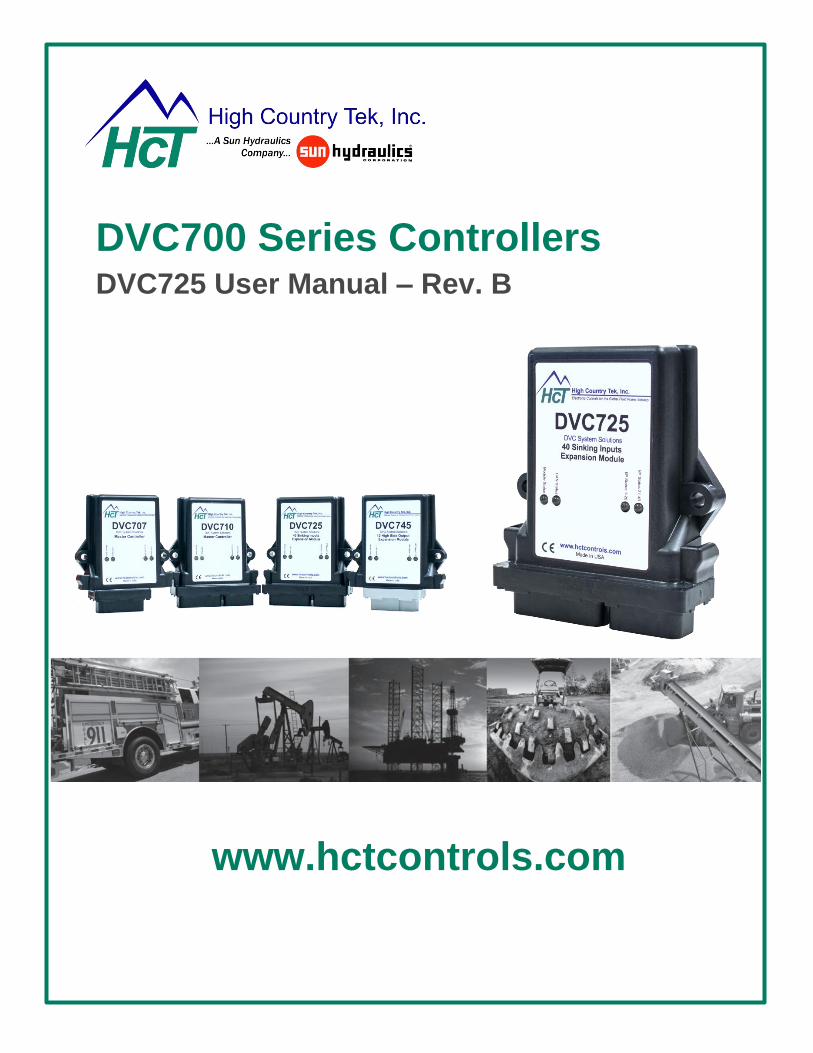
DVC700 Series Controllers DVC725 User Manual – Rev. B
www.hctcontrols.com
DVC700 Series Controllers
DVC725
Page | 2 www.hctcontrols.com 021-00373 Rev. B June 20 2016
Index
Product Overview ............................................................................................................................................................. 3
Hints & Tips ...................................................................................................................................................................... 4
Connections ...................................................................................................................................................................... 5
Pin-Out .............................................................................................................................................................................. 5
Example Configuration ..................................................................................................................................................... 6
Mating Connector Information .......................................................................................................................................... 6
Product Specifications ...................................................................................................................................................... 7
User Interface ................................................................................................................................................................... 7
Operational Specifications ................................................................................................................................................ 8
Communication ................................................................................................................................................................. 8
Inputs ................................................................................................................................................................................ 8
Standards ......................................................................................................................................................................... 9
Certifications ..................................................................................................................................................................... 9
Mounting ......................................................................................................................................................................... 10
Recommended Operating Parameters / Pin Functions .................................................................................................. 11
Diagnostic Indicators ...................................................................................................................................................... 12
Configuration .................................................................................................................................................................. 13
Getting Started ................................................................................................................................................................ 13
Dashboard Window ........................................................................................................................................................ 14
Configuration Window..................................................................................................................................................... 15
J1939 CAN Bus Communication .................................................................................................................................... 19
Status Message Format ................................................................................................................................................. 20
Message Definitions ....................................................................................................................................................... 20
Command / Profile Message Format .............................................................................................................................. 22
Module ID & PGN Map ................................................................................................................................................... 23
Accessories .................................................................................................................................................................... 25
Order Guide .................................................................................................................................................................... 25
Contact & Locations........................................................................................................................................................ 26
DVC700 Series Controllers
DVC725
Page | 3 www.hctcontrols.com 021-00373 Rev. B June 20 2016
Product Overview
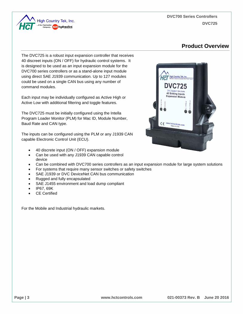
The DVC725 is a robust input expansion controller that receives
40 discreet inputs (ON / OFF) for hydraulic control systems. It
is designed to be used as an input expansion module for the
DVC700 series controllers or as a stand-alone input module
using direct SAE J1939 communication. Up to 127 modules
could be used on a single CAN bus using any number of
command modules.
Each input may be individually configured as Active High or
Active Low with additional filtering and toggle features.
The DVC725 must be initially configured using the Intella
Program Loader Monitor (PLM) for Mac ID, Module Number,
Baud Rate and CAN type.
The inputs can be configured using the PLM or any J1939 CAN
capable Electronic Control Unit (ECU).
40 discrete input (ON / OFF) expansion module
Can be used with any J1939 CAN capable control device
Can be combined with DVC700 series controllers as an input expansion module for large system solutions
For systems that require many sensor switches or safety switches
SAE J1939 or DVC DeviceNet CAN bus communication
Rugged and fully encapsulated
SAE J1455 environment and load dump compliant
IP67, 69K
CE Certified
For the Mobile and Industrial hydraulic markets.
DVC700 Series Controllers
DVC725
Page | 4 www.hctcontrols.com 021-00373 Rev. B June 20 2016
Hints & Tips
Hints & tips for successful application of High Country Tek’s electro-hydraulic control
products
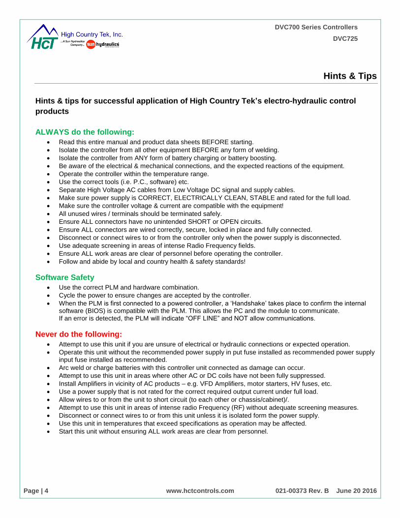
ALWAYS do the following:
Read this entire manual and product data sheets BEFORE starting.
Isolate the controller from all other equipment BEFORE any form of welding.
Isolate the controller from ANY form of battery charging or battery boosting.
Be aware of the electrical & mechanical connections, and the expected reactions of the equipment.
Operate the controller within the temperature range.
Use the correct tools (i.e. P.C., software) etc.
Separate High Voltage AC cables from Low Voltage DC signal and supply cables.
Make sure power supply is CORRECT, ELECTRICALLY CLEAN, STABLE and rated for the full load.
Make sure the controller voltage & current are compatible with the equipment!
All unused wires / terminals should be terminated safely.
Ensure ALL connectors have no unintended SHORT or OPEN circuits.
Ensure ALL connectors are wired correctly, secure, locked in place and fully connected.
Disconnect or connect wires to or from the controller only when the power supply is disconnected.
Use adequate screening in areas of intense Radio Frequency fields.
Ensure ALL work areas are clear of personnel before operating the controller.
Follow and abide by local and country health & safety standards!
Software Safety
Use the correct PLM and hardware combination.
Cycle the power to ensure changes are accepted by the controller.
When the PLM is first connected to a powered controller, a ‘Handshake’ takes place to confirm the internal software (BIOS) is compatible with the PLM. This allows the PC and the module to communicate. If an error is detected, the PLM will indicate “OFF LINE” and NOT allow communications.
Never do the following:
Attempt to use this unit if you are unsure of electrical or hydraulic connections or expected operation.
Operate this unit without the recommended power supply in put fuse installed as recommended power supply input fuse installed as recommended.
Arc weld or charge batteries with this controller unit connected as damage can occur.
Attempt to use this unit in areas where other AC or DC coils have not been fully suppressed.
Install Amplifiers in vicinity of AC products – e.g. VFD Amplifiers, motor starters, HV fuses, etc.
Use a power supply that is not rated for the correct required output current under full load.
Allow wires to or from the unit to short circuit (to each other or chassis/cabinet)/.
Attempt to use this unit in areas of intense radio Frequency (RF) without adequate screening measures.
Disconnect or connect wires to or from this unit unless it is isolated form the power supply.
Use this unit in temperatures that exceed specifications as operation may be affected.
Start this unit without ensuring ALL work areas are clear from personnel.

DVC700 Series Controllers
DVC725
Page | 5 www.hctcontrols.com 021-00373 Rev. B June 20 2016
Connections
Pin-Out
30 Pin Cinch
Pin Function Pin Function Pin Function
A1 N/C B1 POWER COM C1 Input 2
A2 CAN H B2 + POWER IN C2 Input 3
A3 CAN L B3 Input 1 C3 Input 4
D1 Input 5 E1 Input 8 F1 Input 11
D2 Input 6 E2 Input 9 F2 Input 12
D3 Input 7 E3 Input 10 F3 Input 13
G1 Input 14 H1 Input 17 J1 Input 20
G2 Input 15 H2 Input 18 J2 Input 21
G3 Input 16 H3 Input 19 J3 Input 22
K1 Input 23
K2 Input 24
K3 Input 25
18 Pin Cinch
a1 Input 26 b1 Input 29 c1 Input 32
a2 Input 27 b2 Input 30 c2 Input 33
a3 Input 28 b3 Input 31 c3 Input 34
d1 Input 35 e1 Input 38 f1 RXD
d2 Input 36 e2 Input 39 f2 TXD
d3 Input 37 e3 Input 40 f3 POWER COM
DVC700 Series Controllers
DVC725
Page | 6 www.hctcontrols.com 021-00373 Rev. B June 20 2016
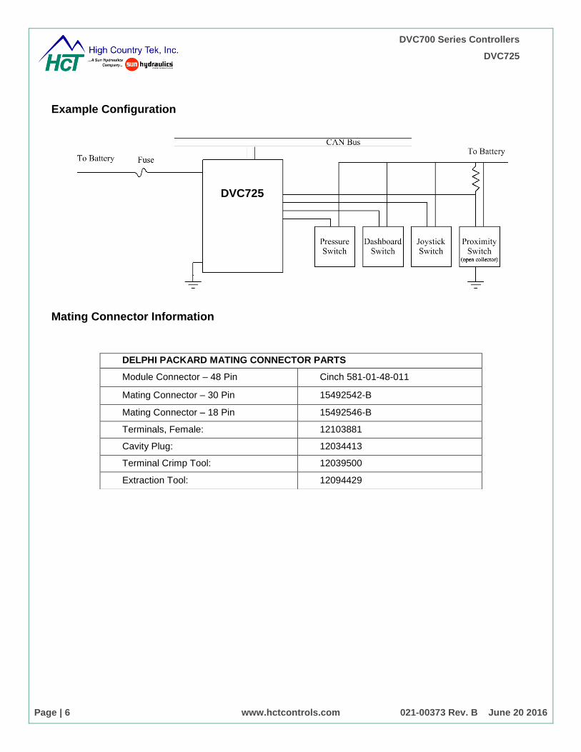
Example Configuration
Mating Connector Information
DELPHI PACKARD MATING CONNECTOR PARTS
Module Connector – 48 Pin Cinch 581-01-48-011
Mating Connector – 30 Pin 15492542-B
Mating Connector – 18 Pin 15492546-B
Terminals, Female: 12103881
Cavity Plug: 12034413
Terminal Crimp Tool: 12039500
Extraction Tool: 12094429
DVC725
DVC700 Series Controllers
DVC725
Page | 7 www.hctcontrols.com 021-00373 Rev. B June 20 2016
Product Specifications
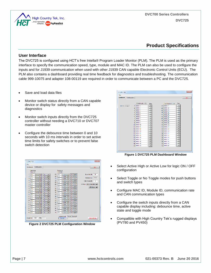
User Interface
The DVC725 is configured using HCT’s free Intella® Program Loader Monitor (PLM). The PLM is used as the primary
interface to specify the communication speed, type, module and MAC ID. The PLM can also be used to configure the
inputs and for J1939 communication when used with other J1939 CAN capable Electronic Control Units (ECU). The
PLM also contains a dashboard providing real time feedback for diagnostics and troubleshooting. The communication
cable 999-10075 and adapter 108-00119 are required in order to communicate between a PC and the DVC725.
Save and load data files
Monitor switch status directly from a CAN capable device or display for safety messages and diagnostics
Monitor switch inputs directly from the DVC725 controller without needing a DVC710 or DVC707 master controller
Configure the debounce time between 0 and 10 seconds with 10 ms intervals in order to set active time limits for safety switches or to prevent false switch detection
Figure 1 DVC725 PLM Dashboard Window
Figure 2 DVC725 PLM Configuration Window
Select Active High or Active Low for logic ON / OFF configuration
Select Toggle or No Toggle modes for push buttons and switch types
Configure MAC ID, Module ID, communication rate and CAN communication types
Configure the switch inputs directly from a CAN capable display including: debounce time, active state and toggle mode
Compatible with High Country Tek’s rugged displays (PV780 and PV450)
DVC700 Series Controllers
DVC725
Page | 8 www.hctcontrols.com 021-00373 Rev. B June 20 2016
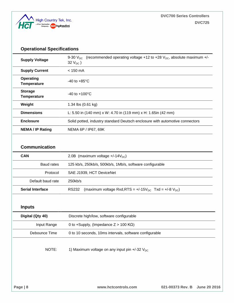
Operational Specifications
Supply Voltage 9-30 VDC (recommended operating voltage +12 to +28 VDC, absolute maximum +/-
32 VDC )
Supply Current < 150 mA
Operating
Temperature -40 to +85°C
Storage
Temperature -40 to +100°C
Weight 1.34 lbs (0.61 kg)
Dimensions L: 5.50 in (140 mm) x W: 4.70 in (119 mm) x H: 1.65in (42 mm)
Enclosure Solid potted, industry standard Deutsch enclosure with automotive connectors
NEMA / IP Rating NEMA 6P / IP67, 69K
Communication
CAN 2.0B (maximum voltage +/-14VDC)
Baud rates 125 kb/s, 250kb/s, 500kb/s, 1Mb/s, software configurable
Protocol SAE J1939, HCT DeviceNet
Default baud rate 250kb/s
Serial Interface RS232 (maximum voltage Rxd,RTS = +/-15VDC Txd = +/-8 VDC)
Inputs
Digital (Qty 40) Discrete high/low, software configurable
Input Range 0 to +Supply, (Impedance Z > 100 KΩ)
Debounce Time 0 to 10 seconds, 10ms intervals, software configurable
NOTE: 1) Maximum voltage on any input pin +/-32 VDC
DVC700 Series Controllers
DVC725
Page | 9 www.hctcontrols.com 021-00373 Rev. B June 20 2016
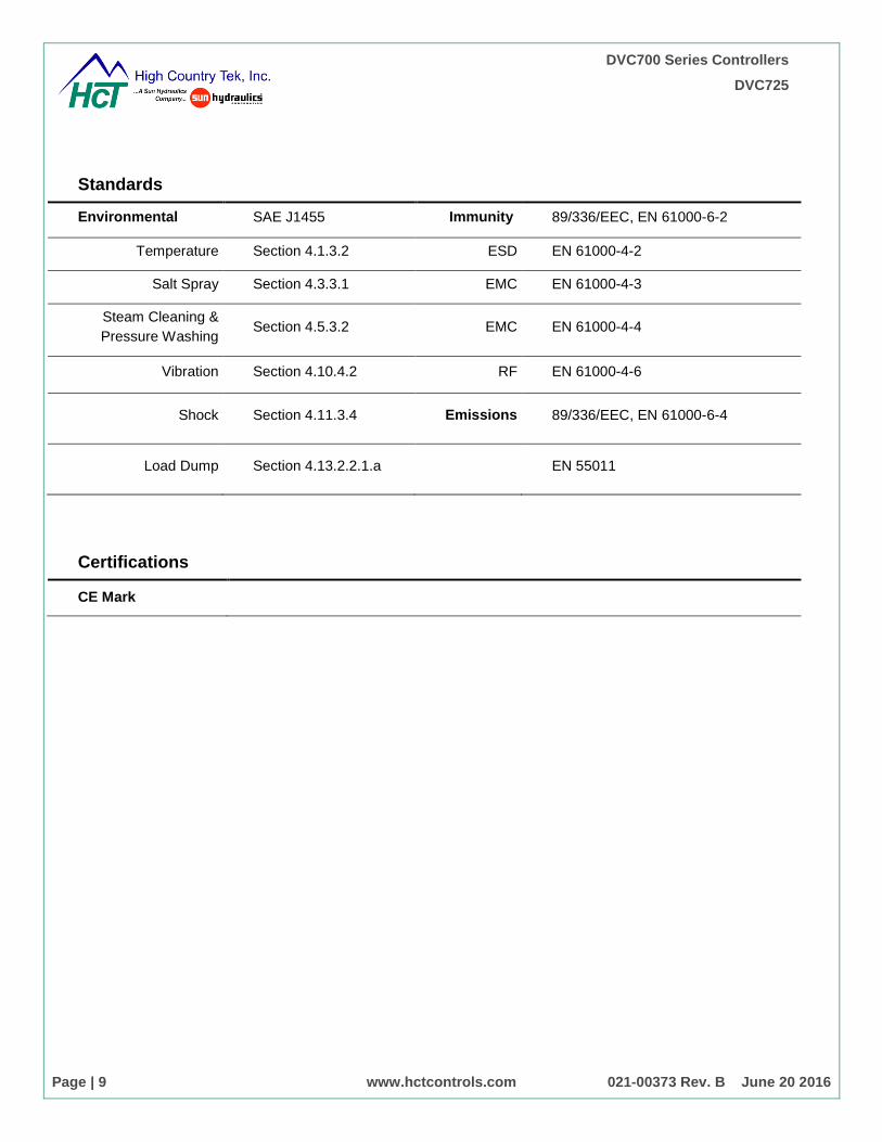
Standards
Environmental SAE J1455 Immunity 89/336/EEC, EN 61000-6-2
Temperature Section 4.1.3.2 ESD EN 61000-4-2
Salt Spray Section 4.3.3.1 EMC EN 61000-4-3
Steam Cleaning &
Pressure Washing Section 4.5.3.2 EMC EN 61000-4-4
Vibration Section 4.10.4.2 RF EN 61000-4-6
Shock Section 4.11.3.4 Emissions 89/336/EEC, EN 61000-6-4
Load Dump Section 4.13.2.2.1.a EN 55011
Certifications
CE Mark

DVC700 Series Controllers
DVC725
Page | 10 www.hctcontrols.com 021-00373 Rev. B June 20 2016
Mounting
Notes:
1) All dimensions are in Inches (Millimeters).
2) Use 1/4 x 20 SAE Grade 2 bolts (M6 x 1 ISO Grade 8)
* Torque to 4 ft-lbs (5.4 N-m) Dry
* Torque to 3 ft-lbs (4.1 N-m) Oiled
2) Mount to a flat hard surface protected from excess heat and moving parts.
3) Factory recommended 18-22 AWG (1.02mm to 0.64mm) TXL, XSL, and GXL automotive grade wire
4) Each Power pin used must be individually fused with an ATO 5, AGC 5 or smaller fuse
1
2
3
A B C D E F G H J K A B C D E F
30 PIN Metri -Pak (P1) 18 PIN Metri-Pak (P2)
1.58 in
5.60 in
4.67 in
4.00 in
Ø0.29 in
2 PLCS
Mount with
1/4" or 6mm
Hardware
Figure 3 DVC725 dimensions
1
2
3
A B C D E F G H J K A B C D E F
30 PIN Metri -Pak (P1) 18 PIN Metri-Pak (P2)
1.58 in
5.60 in
4.67 in
4.00 in
Ø0.29 in
2 PLCS
Mount with
1/4" or 6mm
Hardware

DVC700 Series Controllers
DVC725
Page | 11 www.hctcontrols.com 021-00373 Rev. B June 20 2016
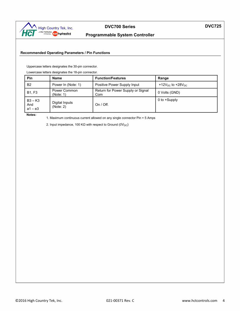
Uppercase letters designates the 30-pin connector.
Lowercase letters designates the 18-pin connector.
Pin Name Function/Features Range
B2 Power In (Note: 1) Positive Power Supply Input +12VDC to +28VDC
B1, F3 Power Common
(Note: 1)
Return for Power Supply or Signal
Com 0 Volts (GND)
B3 – K3
And
a1 – e3
Digital Inputs
(Note: 2) On / Off. 0 to +Supply
Notes: 1. Maximum continuous current allowed on any single connector Pin = 5 Amps
2. Input impedance, 100 KΩ with respect to Ground (0VDC)
Recommended Operating Parameters / Pin Functions

DVC700 Series Controllers
DVC725
Page | 12 www.hctcontrols.com 021-00373 Rev. B June 20 2016
Diagnostic Indicators
Module Status
LED STATE MEANING
Off There is no power applied to the module.
On GREEN The module is operating in a normal condition.
Flashing GREEN Device is in standby state. May need servicing.
On RED Module has an unrecoverable fault.
Flashing RED Low Supply Voltage.
CAN Status
On GREEN Communication established with another Master Controller
Flashing GREEN Waiting to establish communication with the Master Controller
On RED J1939 Communications are in a timed out state
Flashing RED The DVC Devicenet communication is in a timed-out state
Status 1
One GREEN Flash An input has changed its state
On GREEN Normal operation
Status 2
On GREEN Normal operation
DVC700 Series Controllers
DVC725
Page | 13 www.hctcontrols.com 021-00373 Rev. B June 20 2016
Configuration
Getting Started
For programming the DVC725 for use with the DVC707 or DVC710 master controllers, please refer to document
number, 021-00163 DVC710 Family System and Programming Guide. Programmable features of the DVC725 for
use as a standalone module on a J1939 CAN bus is explained below. Regardless of the type of system that the
DVC725 is installed on, the following parameters are set using the Intella® Programming Loader Monitor (PLM)
communicating through the modules serial port using communication cable 999-10075 and adapter 108-00119.
Module Number
MAC ID
Module Baud Rate
CAN bus Type
When used as a standalone module on a J1939 CAN bus the following parameters may be configured by using either
the PLM or J1939 communication protocols:
Debounce Time mS
Active High or Active Low
Toggle or No Toggle
Module Status and Serial Number may all be viewed through the Intella® Programming Loader Monitor.
The DVC725 must be powered up, indicated by the Module Status LED, to communicate with the module. Download
the PLM software from HCT’s website here:
http://www.hctcontrols.com/software/index.htm
Access direct communication through the RS232 port using the communication cable (outlined in the Order Guide).
Once the PLM program is initialized, a Start-Up screen will appear indicating whether communication was successful.
When communication is detected, the DVC725 PLM will automatically open.
DVC700 Series Controllers
DVC725
Page | 14 www.hctcontrols.com 021-00373 Rev. B June 20 2016
Dashboard Window
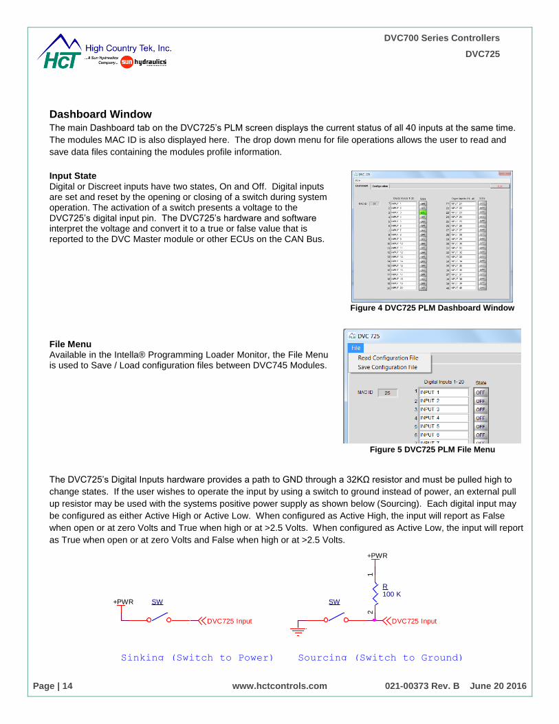
The main Dashboard tab on the DVC725’s PLM screen displays the current status of all 40 inputs at the same time.
The modules MAC ID is also displayed here. The drop down menu for file operations allows the user to read and
save data files containing the modules profile information.
Input State Digital or Discreet inputs have two states, On and Off. Digital inputs are set and reset by the opening or closing of a switch during system operation. The activation of a switch presents a voltage to the DVC725’s digital input pin. The DVC725’s hardware and software interpret the voltage and convert it to a true or false value that is reported to the DVC Master module or other ECUs on the CAN Bus. File Menu Available in the Intella® Programming Loader Monitor, the File Menu is used to Save / Load configuration files between DVC745 Modules.
Figure 4 DVC725 PLM Dashboard Window
Figure 5 DVC725 PLM File Menu
The DVC725’s Digital Inputs hardware provides a path to GND through a 32KΩ resistor and must be pulled high to
change states. If the user wishes to operate the input by using a switch to ground instead of power, an external pull
up resistor may be used with the systems positive power supply as shown below (Sourcing). Each digital input may
be configured as either Active High or Active Low. When configured as Active High, the input will report as False
when open or at zero Volts and True when high or at >2.5 Volts. When configured as Active Low, the input will report
as True when open or at zero Volts and False when high or at >2.5 Volts.
SW
R100 K
12
+PWR
+PWR SW
DVC725 InputDVC725 Input
Sinking (Switch to Power) Sourcing (Switch to Ground)
DVC700 Series Controllers
DVC725
Page | 15 www.hctcontrols.com 021-00373 Rev. B June 20 2016
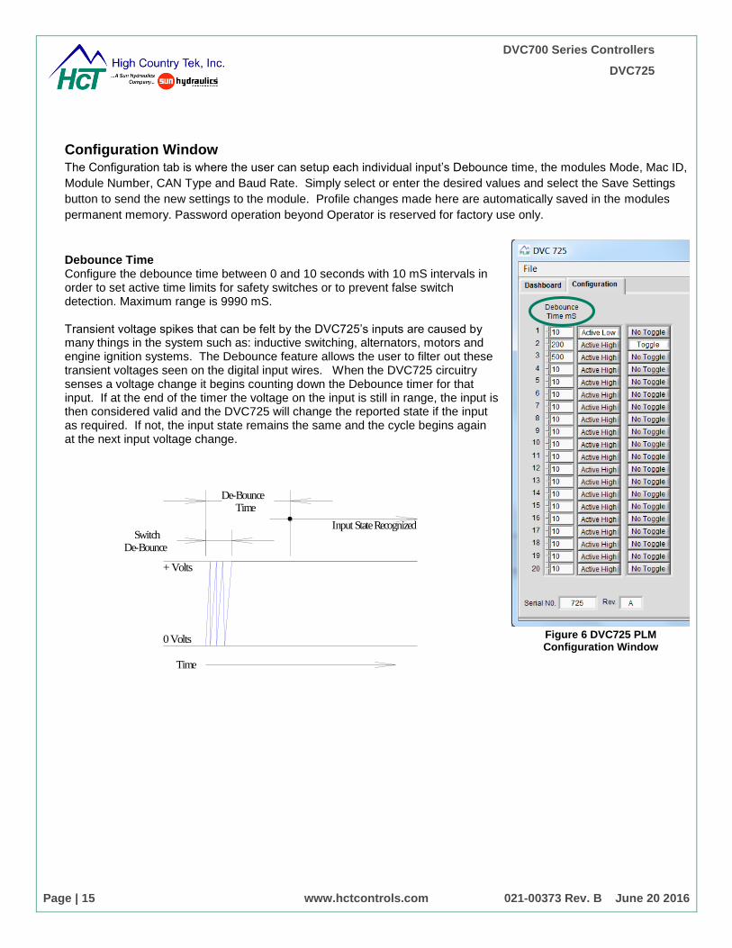
Configuration Window
The Configuration tab is where the user can setup each individual input’s Debounce time, the modules Mode, Mac ID,
Module Number, CAN Type and Baud Rate. Simply select or enter the desired values and select the Save Settings
button to send the new settings to the module. Profile changes made here are automatically saved in the modules
permanent memory. Password operation beyond Operator is reserved for factory use only.
Debounce Time Configure the debounce time between 0 and 10 seconds with 10 mS intervals in order to set active time limits for safety switches or to prevent false switch detection. Maximum range is 9990 mS. Transient voltage spikes that can be felt by the DVC725’s inputs are caused by many things in the system such as: inductive switching, alternators, motors and engine ignition systems. The Debounce feature allows the user to filter out these transient voltages seen on the digital input wires. When the DVC725 circuitry senses a voltage change it begins counting down the Debounce timer for that input. If at the end of the timer the voltage on the input is still in range, the input is then considered valid and the DVC725 will change the reported state if the input as required. If not, the input state remains the same and the cycle begins again at the next input voltage change.
Figure 6 DVC725 PLM Configuration Window
0 Volts
+ Volts
SwitchDe-Bounce
De-BounceTime
Input State Recognized
Time

DVC700 Series Controllers
DVC725
Page | 16 www.hctcontrols.com 021-00373 Rev. B June 20 2016
Active High / Active Low (Input Polarity) Select Active High or Active Low for logic ON / OFF configuration. When Active High is selected, the variable is true when the input is high (+ Voltage). When Active Low is selected, the variable is true when the input is low (ground or floating). Toggle Select Toggle or No Toggle modes for push buttons and switch types. The Toggle feature causes the module to latch the input to its complimentary output state (ON or OFF) for each valid rising or falling pulse with respect to the Polarity setting. A valid pulse is a pulse with a period that satisfies the debounce time. With Toggle selected the output will turn ON when a push button is depressed and released once and will remain ON until the push button is depressed and released a second time. With No Toggle selected, the output will turn on when the button is depressed but turn off when the button is released. No Toggle mode is most common when using ON / OFF switches. Serial Number Displays the modules Serial Number (display only). Revision Number Displays the modules Hardware Revision Number (display only).
Figure 7 DVC725 PLM Configuration Window

DVC700 Series Controllers
DVC725
Page | 17 www.hctcontrols.com 021-00373 Rev. B June 20 2016
MAC ID The Media Access Control Address that the module uses to communicate to a DVC Master Module when in DVC DeviceNet mode. Range: 1 to 63 Software Version Version of the firmware installed into the module (display only). Module ID The modules Identification Number used when in J1939 Mode to determine the PGN numbers employed for CAN communication. (Must be unique with respect to each HCT module on the bus.) Range: 1 to 127 CAN Type Pull down menu that allows the user to select between J1939 mode and DVC DeviceNet Mode. Baud Rate Pull down menu that allows the user to select between available Baud Rates.
Figure 8 DVC725 PLM Configuration tab
Figure 9 DVC725 CAN Type
Figure 10 DVC725 Baud Rate
DVC700 Series Controllers
DVC725
Page | 18 www.hctcontrols.com 021-00373 Rev. B June 20 2016
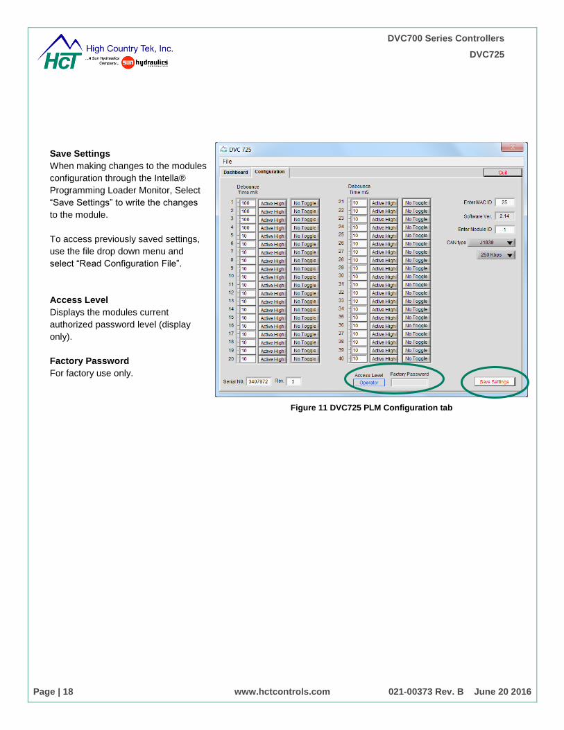
Save Settings
When making changes to the modules
configuration through the Intella®
Programming Loader Monitor, Select
“Save Settings” to write the changes
to the module.
To access previously saved settings,
use the file drop down menu and
select “Read Configuration File”.
Access Level
Displays the modules current
authorized password level (display
only).
Factory Password
For factory use only.
Figure 11 DVC725 PLM Configuration tab
DVC700 Series Controllers
DVC725
Page | 19 www.hctcontrols.com 021-00373 Rev. B June 20 2016
J1939 CAN Bus Communication
The DVC725 may be installed directly on a J1939 CAN bus and operate without the need for a DVC710/707 Master
module using the following message format. When in J1939 Mode, the DVC725 will automatically broadcast its status
on the CAN bus using a predefined PGN determined by the Module number assigned to the input module.
The DVC725 transmits and receives all J1939 messages using Source Address 0x22 (Aux Valve Controller) only.
The Modules ID number determines which PGN Numbers the module will transmit and receive on the J1939 Bus. It
sets the PDU Specific (PS) part of the message header for the Configuration Message that the unit will accept when
being configured over the J1939 Bus. For example, a unit with the Module ID of 1 would accept PGN: 0xFF01 SA:
0x22 as a command input. Using this format, the user may command up to 127 separate expansion modules on a
single Bus using any number of master controllers. Valid module ID numbers are 1 through 127.
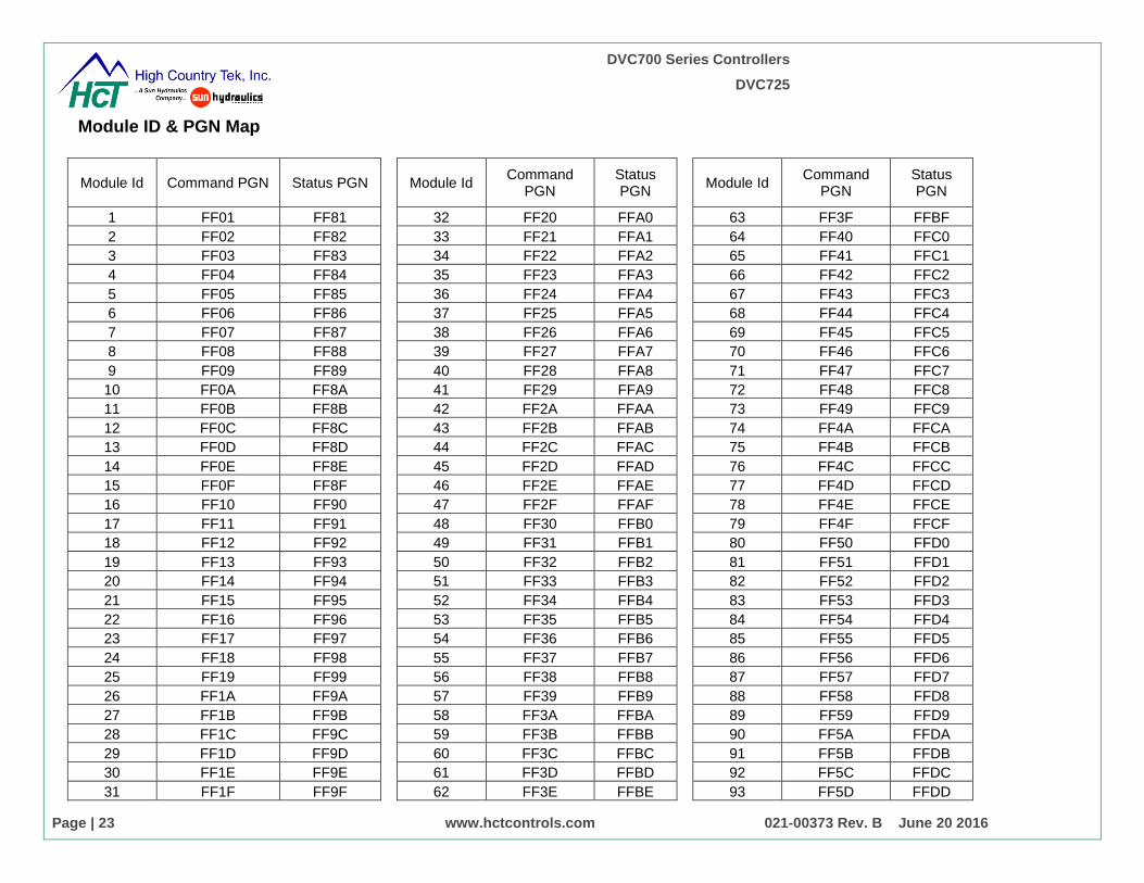
The PGN numbers 0xFF01 through 0xFF7F are used as Configuration Messages for the DVC725. PGN numbers
0xFF00 and 0xFF80 are reserved for special functions. PGN numbers 0xFF81 through 0xFFFF are used as the
complementary Status Messages transmitted by the DVC725. The user can calculate the PGN that the Module will
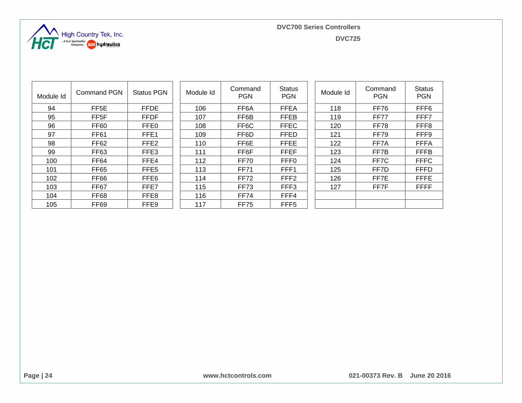
transmit as its Status Message by adding 0x80 to the Module ID. For example, a unit with a module ID of 61 would
accept PGN 0xFF3D as a command message and would transmit PGN 0xFFBD as its Status Message,0xFF3D +
0x80 = 0xFFBD. A list of Module IDs, Command Message PGNs and Status Message PGNs is listed below.
The DVC725 will transmit its state message whenever there is a state change on one of the inputs or at least once
every 1000mS. The DVC725 will transmit a Profile Acknowledgment message each time that it receives and
processes a valid profile message. The Profile Acknowledgment message will contain the exact same data field that
was received in the profile message and may be used by the controlling ECU to verify that the input was profiled
correctly.

DVC700 Series Controllers
DVC725
Page | 20 www.hctcontrols.com 021-00373 Rev. B June 20 2016
Status Message Format
Transmission Cycle Time: 1000mS or on change. Data Length: 8 Data Page: 1 PDU Format: 255 PDU Specific: Module ID + 128 (0x80)
Priority: 6 Parameter Group Number: 65409 Through 65535 (FF81 Through FFFF)
Start Position Length Parameter Name
1.1 1 Byte Multiplexer 2.1 1 Byte Module Type 3.1 1 bit Input 1 State 3.2 1 bit Input 2 State 33 1 bit Input 3 State … … … 7.6 1 bit Input 38 State 7.7 1 bit Input 39 State 7.8 1 bit Input 40 State
Message Definitions
Multiplexer Data Length: 1 Bytes
Resolution: 1 bit, 0 offset
Data Range: 0 to 255
Operational Range: 1 to 5
Definitions: 0 – Invalid
1 – Profile Mode
2 – Profile Acknowledgement
3 – Reserved
4 – Command Outputs (DVC745)
5 – Save Profile to Permanent Memory
6…255 – Reserved
Module Type Data Length: 1 Byte
Resolution: 1 bit, 0 offset
Data Range: 0 to 255
Operational Range: 1 to 2
Definitions: 1 – DVC725
2 – DVC745

DVC700 Series Controllers
DVC725
Page | 21 www.hctcontrols.com 021-00373 Rev. B June 20 2016
Input State Data Length: 1 bit
Resolution: 1 bit, 0 offset
Data Range: 0 to 1
Operational Range: 0 to 1
Definitions: 0 – Input Off (False)
1 – Input On (True)
Input Index Number Data Length: 1 Byte
Resolution: 1 bit, 0 offset
Data Range: 0 to 255
Operational Range: 1 to 40
Definitions: 1 – Input 1
2 – Input 2 …
Debounce x10mS Data Length: 10 bits
Resolution: 10mS / bit, 0 offset
Data Range: 0 to 1023
Operational Range: 1 to 999 (values >999 are ignored)
Active State Mode Data Length: 1 bit
Resolution: 1 bit, 0 offset
Data Range: 0 to 1
Operational Range: 0 to 1
Definitions: 0 – Active High
1 – Active Low
Toggle Mode Data Length: 1 bit
Resolution: 1 bit, 0 offset
Data Range: 0 to 1
Operational Range: 0 to 1
Definitions: 0 – Toggle Mode Off
1 – Toggle Mode On
DVC700 Series Controllers
DVC725
Page | 22 www.hctcontrols.com 021-00373 Rev. B June 20 2016
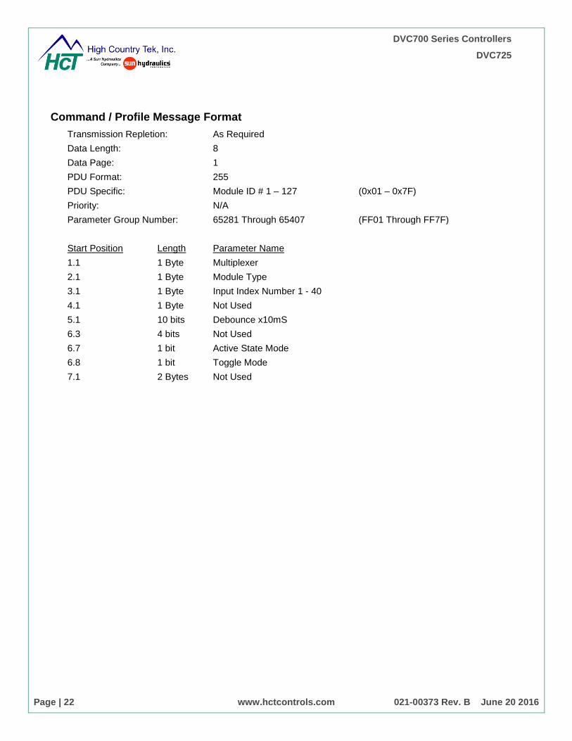
Command / Profile Message Format
Transmission Repletion: As Required Data Length: 8 Data Page: 1 PDU Format: 255 PDU Specific: Module ID # 1 – 127 (0x01 – 0x7F)
Priority: N/A Parameter Group Number: 65281 Through 65407 (FF01 Through FF7F)
Start Position Length Parameter Name 1.1 1 Byte Multiplexer 2.1 1 Byte Module Type 3.1 1 Byte Input Index Number 1 - 40 4.1 1 Byte Not Used 5.1 10 bits Debounce x10mS
6.3 4 bits Not Used
6.7 1 bit Active State Mode
6.8 1 bit Toggle Mode
7.1 2 Bytes Not Used
DVC700 Series Controllers
DVC725
Page | 23 www.hctcontrols.com 021-00373 Rev. B June 20 2016
Module ID & PGN Map
Module Id Command PGN Status PGN
Module Id Command
PGN Status PGN
Module Id Command
PGN Status PGN
1 FF01 FF81
32 FF20 FFA0
63 FF3F FFBF
2 FF02 FF82
33 FF21 FFA1
64 FF40 FFC0
3 FF03 FF83
34 FF22 FFA2
65 FF41 FFC1
4 FF04 FF84
35 FF23 FFA3
66 FF42 FFC2
5 FF05 FF85
36 FF24 FFA4
67 FF43 FFC3
6 FF06 FF86
37 FF25 FFA5
68 FF44 FFC4
7 FF07 FF87
38 FF26 FFA6
69 FF45 FFC5
8 FF08 FF88
39 FF27 FFA7
70 FF46 FFC6
9 FF09 FF89
40 FF28 FFA8
71 FF47 FFC7
10 FF0A FF8A
41 FF29 FFA9
72 FF48 FFC8
11 FF0B FF8B
42 FF2A FFAA
73 FF49 FFC9
12 FF0C FF8C
43 FF2B FFAB
74 FF4A FFCA
13 FF0D FF8D
44 FF2C FFAC
75 FF4B FFCB
14 FF0E FF8E
45 FF2D FFAD
76 FF4C FFCC
15 FF0F FF8F
46 FF2E FFAE
77 FF4D FFCD
16 FF10 FF90
47 FF2F FFAF
78 FF4E FFCE
17 FF11 FF91
48 FF30 FFB0
79 FF4F FFCF
18 FF12 FF92
49 FF31 FFB1
80 FF50 FFD0
19 FF13 FF93
50 FF32 FFB2
81 FF51 FFD1
20 FF14 FF94
51 FF33 FFB3
82 FF52 FFD2
21 FF15 FF95
52 FF34 FFB4
83 FF53 FFD3
22 FF16 FF96
53 FF35 FFB5
84 FF54 FFD4
23 FF17 FF97
54 FF36 FFB6
85 FF55 FFD5
24 FF18 FF98
55 FF37 FFB7
86 FF56 FFD6
25 FF19 FF99
56 FF38 FFB8
87 FF57 FFD7
26 FF1A FF9A
57 FF39 FFB9
88 FF58 FFD8
27 FF1B FF9B
58 FF3A FFBA
89 FF59 FFD9
28 FF1C FF9C
59 FF3B FFBB
90 FF5A FFDA
29 FF1D FF9D
60 FF3C FFBC
91 FF5B FFDB
30 FF1E FF9E
61 FF3D FFBD
92 FF5C FFDC
31 FF1F FF9F
62 FF3E FFBE
93 FF5D FFDD
DVC700 Series Controllers
DVC725
Page | 24 www.hctcontrols.com 021-00373 Rev. B June 20 2016
Module Id
Command PGN Status PGN
Module Id Command
PGN Status PGN
Module Id Command
PGN Status PGN
94 FF5E FFDE 106 FF6A FFEA 118 FF76 FFF6
95 FF5F FFDF
107 FF6B FFEB
119 FF77 FFF7
96 FF60 FFE0
108 FF6C FFEC
120 FF78 FFF8
97 FF61 FFE1
109 FF6D FFED
121 FF79 FFF9
98 FF62 FFE2
110 FF6E FFEE
122 FF7A FFFA
99 FF63 FFE3
111 FF6F FFEF
123 FF7B FFFB
100 FF64 FFE4
112 FF70 FFF0
124 FF7C FFFC
101 FF65 FFE5
113 FF71 FFF1
125 FF7D FFFD
102 FF66 FFE6
114 FF72 FFF2
126 FF7E FFFE
103 FF67 FFE7
115 FF73 FFF3
127 FF7F FFFF
104 FF68 FFE8
116 FF74 FFF4
105 FF69 FFE9
117 FF75 FFF5
DVC700 Series Controllers
DVC725
Page | 25 www.hctcontrols.com 021-00373 Rev. B June 20 2016
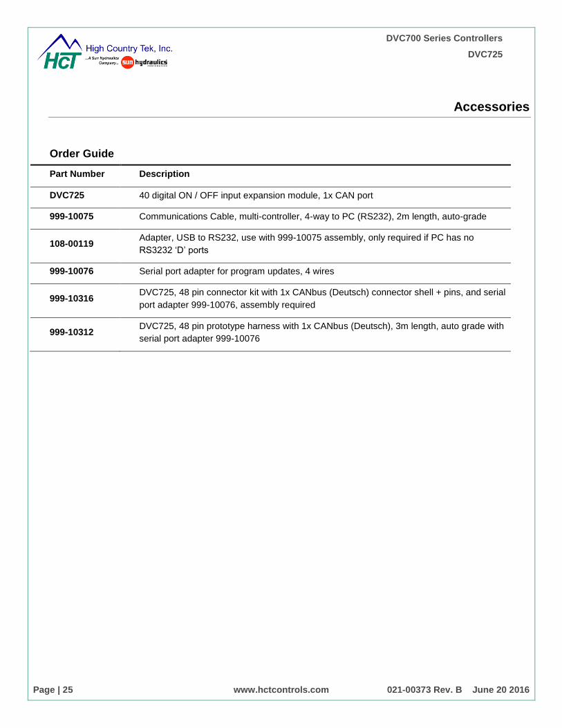
Accessories
Order Guide
Part Number Description
DVC725 40 digital ON / OFF input expansion module, 1x CAN port
999-10075 Communications Cable, multi-controller, 4-way to PC (RS232), 2m length, auto-grade
108-00119 Adapter, USB to RS232, use with 999-10075 assembly, only required if PC has no
RS3232 ‘D’ ports
999-10076 Serial port adapter for program updates, 4 wires
999-10316 DVC725, 48 pin connector kit with 1x CANbus (Deutsch) connector shell + pins, and serial
port adapter 999-10076, assembly required
999-10312 DVC725, 48 pin prototype harness with 1x CANbus (Deutsch), 3m length, auto grade with
serial port adapter 999-10076
DVC700 Series Controllers
DVC725
Page | 26 www.hctcontrols.com 021-00373 Rev. B June 20 2016
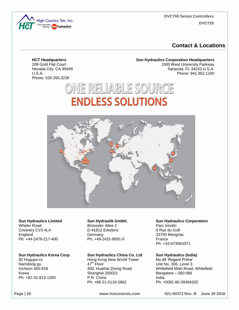
Contact & Locations
HCT Headquarters 208 Gold Flat Court Nevada City, CA 95949 U.S.A. Phone: 530.265.3236
Sun Hydraulics Corporation Headquarters 1500 West University Parkway
Sarasota, FL 34243 U.S.A. Phone: 941.362.1200
Sun Hydraulics Limited Wheler Road Coventry CV3 4LA England Ph: +44-2476-217-400
Sun Hydraulik GmbH. Brüsseler Allee 2 D-41812 Erkelenz Germany Ph: +49-2431-8091-0
Sun Hydraulics Corporation Parc Innolin 6 Rue du Golf 33700 Merignac France Ph: +33-673063371
Sun Hydraulics Korea Corp. 92 Hogupo-ro Namdong-gu Incheon 405-818 Korea Ph: +82-32-813-1350
Sun Hydraulics China Co. Ltd Hong Kong New World Tower 47
th Floor
300, Huaihai Zhong Road Shanghai 200021 P.R. China Ph: +86-21-5116-2862
Sun Hydraulics (India) No.48 ‘Regent Prime’ Unit No. 306, Level 3 Whitefield Main Road, Whitefield Bangalore – 560 066 India Ph: +0091-80-28456325
©2016 High Country Tek, Inc. 021-00371 Rev. C www.hctcontrols.com 1
DVC700 Series
Programmable System Controller
DVC725
Configured Using HCT’s Program Loader Monitor (PLM)
40 digital ON / OFF input expansion module, 1 CAN interface
Supply voltage 9-30Vdc
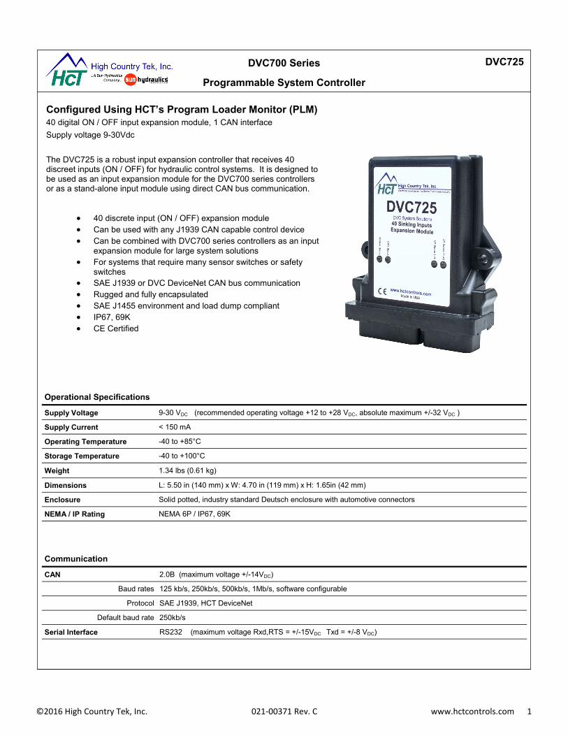
The DVC725 is a robust input expansion controller that receives 40 discreet inputs (ON / OFF) for hydraulic control systems. It is designed to be used as an input expansion module for the DVC700 series controllers or as a stand-alone input module using direct CAN bus communication.
40 discrete input (ON / OFF) expansion module
Can be used with any J1939 CAN capable control device
Can be combined with DVC700 series controllers as an input
expansion module for large system solutions
For systems that require many sensor switches or safety
switches
SAE J1939 or DVC DeviceNet CAN bus communication
Rugged and fully encapsulated
SAE J1455 environment and load dump compliant
IP67, 69K
CE Certified
Operational Specifications
Supply Voltage 9-30 VDC (recommended operating voltage +12 to +28 VDC, absolute maximum +/-32 VDC )
Supply Current < 150 mA
Operating Temperature -40 to +85°C
Storage Temperature -40 to +100°C
Weight 1.34 lbs (0.61 kg)
Dimensions L: 5.50 in (140 mm) x W: 4.70 in (119 mm) x H: 1.65in (42 mm)
Enclosure Solid potted, industry standard Deutsch enclosure with automotive connectors
NEMA / IP Rating NEMA 6P / IP67, 69K
Communication
CAN 2.0B (maximum voltage +/-14VDC)
Baud rates 125 kb/s, 250kb/s, 500kb/s, 1Mb/s, software configurable
Protocol SAE J1939, HCT DeviceNet
Default baud rate 250kb/s
Serial Interface RS232 (maximum voltage Rxd,RTS = +/-15VDC Txd = +/-8 VDC)

©2016 High Country Tek, Inc. 021-00371 Rev. C www.hctcontrols.com 2
Inputs
Digital (Qty 40) Discrete high/low, software configurable
Input Range 0 to +Supply, (Impedance Z > 100 KΩ)
Debounce Time 0 to 10 seconds, 10ms intervals, software configurable
NOTE: 1) Maximum voltage on any input pin +/-32 VDC
DVC700 Series
Programmable System Controller
DVC725
Certifications
CE
Standards
Environmental SAE J1455 Immunity 89/336/EEC, EN 61000-6-2
Temperature Section 4.1.3.2 ESD EN 61000-4-2
Salt Spray Section 4.3.3.1 EMC EN 61000-4-3
Steam Cleaning & Pressure
Washing Section 4.5.3.2 EMC EN 61000-4-4
Vibration Section 4.10.4.2 RF EN 61000-4-6
Shock Section 4.11.3.4 Emissions 89/336/EEC, EN 61000-6-4
Load Dump Section 4.13.2.2.1.a EN 55011

©2016 High Country Tek, Inc. 021-00371 Rev. C www.hctcontrols.com 3
DVC700 Series
Programmable System Controller
DVC725
Pin Out
30 Pin Cinch
Pin Function Pin Function Pin Function
A1 N/C B1 POWER COM C1 Input 2
A2 CAN H B2 + POWER IN C2 Input 3
A3 CAN L B3 Input 1 C3 Input 4
D1 Input 5 E1 Input 8 F1 Input 11
D2 Input 6 E2 Input 9 F2 Input 12
D3 Input 7 E3 Input 10 F3 Input 13
G1 Input 14 H1 Input 17 J1 Input 20
G2 Input 15 H2 Input 18 J2 Input 21
G3 Input 16 H3 Input 19 J3 Input 22
K1 Input 23
K2 Input 24
K3 Input 25
18 Pin Cinch
a1 Input 26 b1 Input 29 c1 Input 32
a2 Input 27 b2 Input 30 c2 Input 33
a3 Input 28 b3 Input 31 c3 Input 34
d1 Input 35 e1 Input 38 f1 RXD
d2 Input 36 e2 Input 39 f2 TXD
d3 Input 37 e3 Input 40 f3 POWER COM
©2016 High Country Tek, Inc. 021-00371 Rev. C www.hctcontrols.com 4
DVC700 Series
Programmable System Controller
DVC725
Uppercase letters designates the 30-pin connector.
Lowercase letters designates the 18-pin connector.
Pin Name Function/Features Range
B2 Power In (Note: 1) Positive Power Supply Input +12VDC to +28VDC
B1, F3 Power Common (Note: 1)
Return for Power Supply or Signal Com
0 Volts (GND)
B3 – K3 And a1 – e3
Digital Inputs (Note: 2)
On / Off.
0 to +Supply
Notes: 1. Maximum continuous current allowed on any single connector Pin = 5 Amps
2. Input impedance, 100 KΩ with respect to Ground (0VDC)
Recommended Operating Parameters / Pin Functions

©2016 High Country Tek, Inc. 021-00371 Rev. C www.hctcontrols.com 5
DVC700 Series
Programmable System Controller
DVC725
LED Diagnostic Indicators
Module Status
LED STATE MEANING
Off There is no power applied to the module.
On GREEN The module is operating in a normal condition.
Flashing GREEN Device is in standby state. May need servicing.
On RED Module has an unrecoverable fault.
Flashing RED Low Supply Voltage.
CAN Status
On GREEN Communication established with another Master Controller
Flashing GREEN Waiting to establish communication with the Master Controller
On RED J1939 Communications are in a timed out state
Flashing RED The DVC Devicenet communication is in a timed-out state
Status 1
One GREEN Flash An input has changed its state
On GREEN Normal operation
Status 2
On GREEN Normal operation
©2016 High Country Tek, Inc. 021-00371 Rev. C www.hctcontrols.com 6
DVC700 Series
Programmable System Controller
DVC725
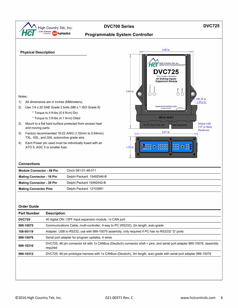
Physical Description
Connections
Module Connector - 48 Pin Cinch 581-01-48-011
Mating Connector - 18 Pin Delphi Packard 15492546-B
Mating Connector - 30 Pin Delphi Packard 15492542-B
Mating Connector Pins Delphi Packard 12103881
Order Guide
Part Number Description
DVC725 40 digital ON / OFF input expansion module, 1x CAN port
999-10075 Communications Cable, multi-controller, 4-way to PC (RS232), 2m length, auto-grade
108-00119 Adapter, USB to RS232, use with 999-10075 assembly, only required if PC has no RS3232 ‘D’ ports
999-10076 Serial port adapter for program updates, 4 wires
999-10316 DVC725, 48 pin connector kit with 1x CANbus (Deutsch) connector shell + pins, and serial port adapter 999-10076, assembly
required
999-10312 DVC725, 48 pin prototype harness with 1x CANbus (Deutsch), 3m length, auto grade with serial port adapter 999-10076
Notes:
1) All dimensions are in Inches (Millimeters).
2) Use 1/4 x 20 SAE Grade 2 bolts (M6 x 1 ISO Grade 8)
* Torque to 4 ft-lbs (5.4 N-m) Dry
* Torque to 3 ft-lbs (4.1 N-m) Oiled
2) Mount to a flat hard surface protected from excess heat
and moving parts.
3) Factory recommended 18-22 AWG (1.02mm to 0.64mm)
TXL, XSL, and GXL automotive grade wire
4) Each Power pin used must be individually fused with an
ATO 5, AGC 5 or smaller fuse 1
2
3
A B C D E F G H J K A B C D E F
30 PIN Metri -Pak (P1) 18 PIN Metri-Pak (P2)
1.58 in
5.60 in
4.67 in
4.00 in
Ø0.29 in
2 PLCS
Mount with
1/4" or 6mm
Hardware

©2016 High Country Tek, Inc. 021-00371 Rev. C www.hctcontrols.com 7
DVC700 Series
Programmable System Controller
DVC725
DVC725
DVC DeviceNet
DVC710
Direct CAN bus Control Configuration
Program Loader Monitor Configuration
The DVC725 can be used with any programmable J1939 capable control unit.
Receive switch input status directly from the DVC725 controller
without needing a DVC710 or DVC707 master controller
Configure the switch inputs directly from a CAN capable display
including: debounce time, active state and toggle mode
Monitor switch status directly from a CAN capable display for
safety messages and diagnostics
Compatible with High Country Tek’s rugged displays (PV780 and
PV450)
The DVC725 is configured using HCT’s free Program Loader Monitor (PLM). The PLM is the separate graphical user interface component to the Intella Software Suite ™ and can be downloaded from HCT’s website. Conviguration through the PLM allows the user to;
Configure the debounce time between 0 and 10 seconds with 10 ms
intervals in order to set active time limits for safety switches or to pre-vent false switch detection
Select Active High or Active Low for logic ON / OFF configuration
Select Toggle or No Toggle modes for push buttons and switch types
Configure MAC ID, Module ID, communication rate and CAN
Note: For more details on how to configure the DVC725, refer to the DVC725 User Manual.
Note: For more details on how to configure the DVC725, refer to the DVC725 User Manual.
Expansion Module
Master Controller
DVC725 PLM Dashboard Window
DVC725 PLM Configuration Window
DVC725
Display
Expansion Module
SAE J1939

©2016 High Country Tek, Inc. 021-00371 Rev. C www.hctcontrols.com 8
DVC700 Series
Programmable System Controller
DVC725
HCT Headquarters 208 Gold Flat Court Nevada City, CA 95949 U.S.A. Phone: 530.265.3236
Sun Hydraulics Corporation Headquarters 1500 West University Parkway
Sarasota, FL 34243 U.S.A. Phone: 941.362.1200
Sun Hydraulics Limited Wheler Road Coventry CV3 4LA England Ph: +44-2476-217-400
Sun Hydraulik GmbH. Brüsseler Allee 2 D-41812 Erkelenz Germany Ph: +49-2431-8091-0
Sun Hydraulics Corporation Parc Innolin 6 Rue du Golf 33700 Merignac France Ph: +33-673063371
Sun Hydraulics Korea Corp. 92 Hogupo-ro Namdong-gu Incheon 405-818 Korea Ph: +82-32-813-1350
Sun Hydraulics China Co. Ltd Hong Kong New World Tower 47th Floor 300, Huaihai Zhong Road Shanghai 200021 P.R. China Ph: +86-21-5116-2862
Sun Hydraulics (India) No.48 ‘Regent Prime’ Unit No. 306, Level 3 Whitefield Main Road, Whitefield Bangalore – 560 066 India Ph: +0091-80-28456325


![Programmable Controllers MELSEC-Q series [QnU]](https://img.pdfslide.net/doc/110x75/588c76911a28ab3f218b9b52/programmable-controllers-melsec-q-series-qnu.jpg)