Embed Size (px)
Citation preview
1
DVI Interface
• The outline: The reasons for digital interface of a monitor – the transfer from VGA to DVI. DVI v. analog interface. The principles of LCD control through DVI interface. The link between DVI and monitor and its possible bandwidth. 8b/10b encoding in DVI. The internal structure of LCD monitor – its context with the interface.
2
Note – monitors controlled by analog signals • CRT monitors are controlled by analog voltage. i. e. the
level of analog signal delivered through the cable from graphics adapter to monitor determines the level of R, G, B colors. This voltage accelerates the beam of electrons hitting the fluorescent layer. Mono monitor – one beam of electrons. Color monitor – three beams of electrons.
• The principle: The level of analog signal determines the energy with which electrons are accelerated, then the speed with which they are hitting the fluorescent layer is given by the
3
level of voltage → different level of displayed R, G, B components.
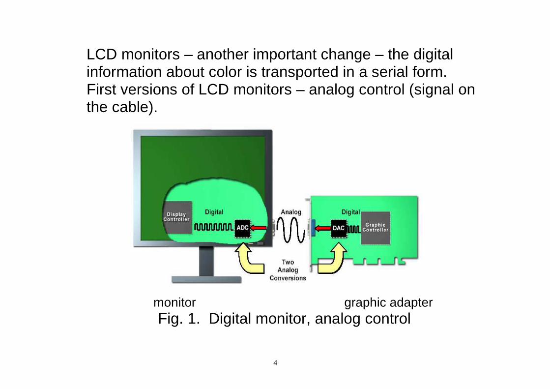
• Situation which existed when LCD monitors came into use: LCD monitor was internally controlled by digital values representing color values. The internal structure of LCD monitors was digital. If controlled by an analog signal (voltages representing information about colors coming from graphics adapter) then it was necessary: In graphics adapter - to convert the information about color from digital form (in video RAM) to analog form (DAC in graphics adapter – digital to analog converter) and transport it through the cable to monitor and then use ADC (analog to digital converter) in monitor to convert it back to digital form through DVI connection.
4
LCD monitors – another important change – the digital information about color is transported in a serial form. First versions of LCD monitors – analog control (signal on the cable).
monitor graphic adapter Fig. 1. Digital monitor, analog control
5
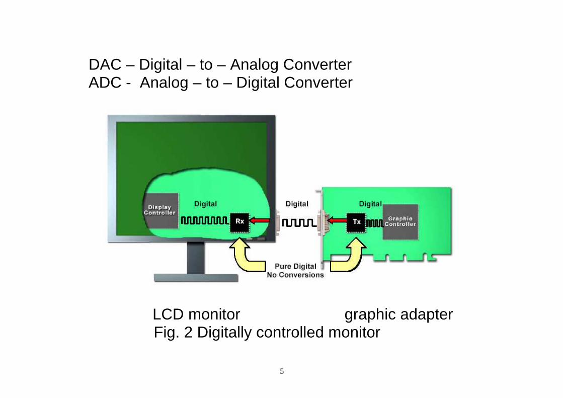
DAC – Digital – to – Analog Converter ADC - Analog – to – Digital Converter
LCD monitor graphic adapter Fig. 2 Digitally controlled monitor
6
7
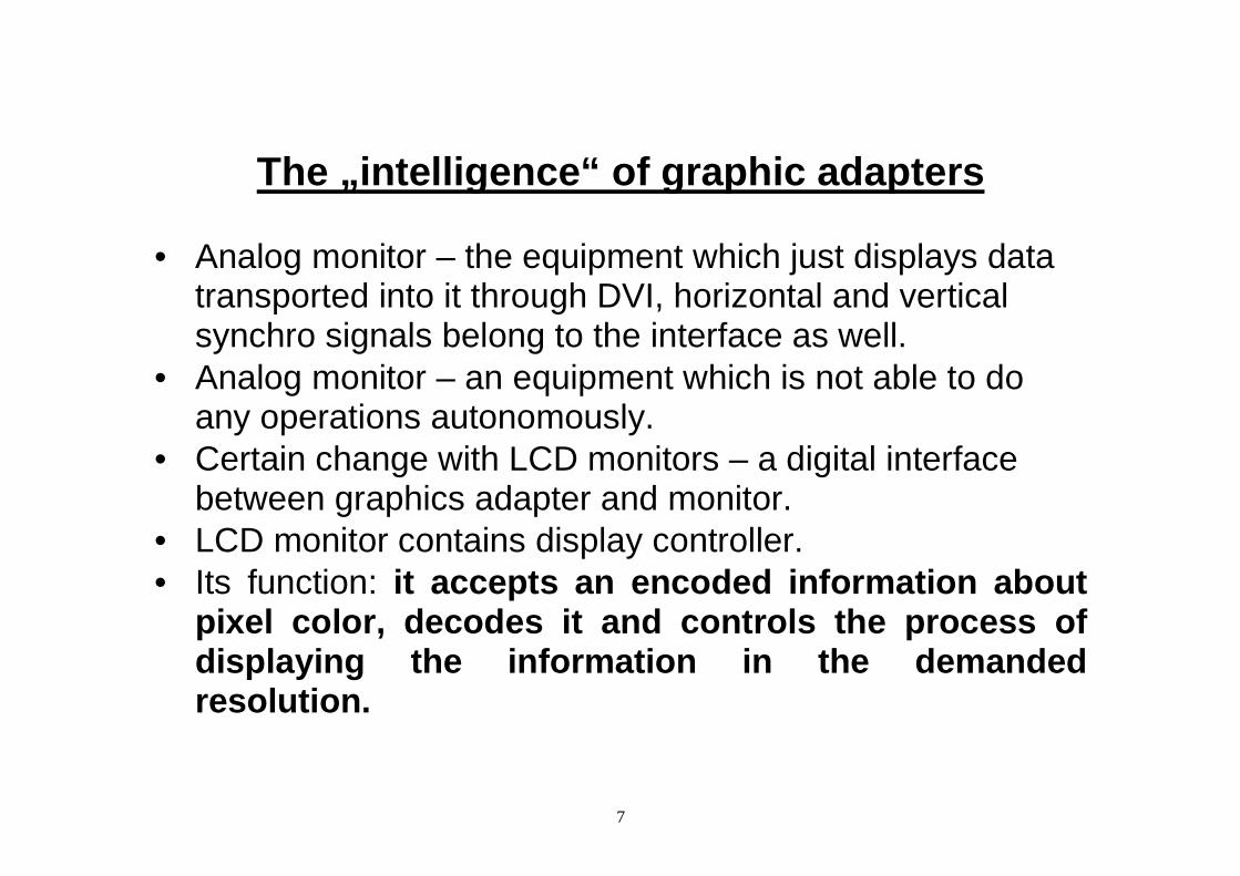
The „intelligence“ of graphic adapters
• Analog monitor – the equipment which just displays data
transported into it through DVI, horizontal and vertical synchro signals belong to the interface as well.
• Analog monitor – an equipment which is not able to do any operations autonomously.
• Certain change with LCD monitors – a digital interface between graphics adapter and monitor.
• LCD monitor contains display controller. • Its function: it accepts an encoded information about
pixel color, decodes it and controls the process of displaying the information in the demanded resolution.
8
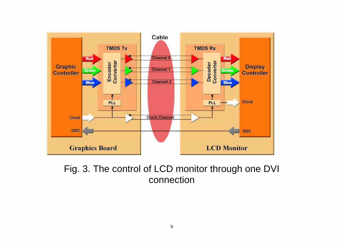
Fig. 3. The control of LCD monitor through one DVI connection
9
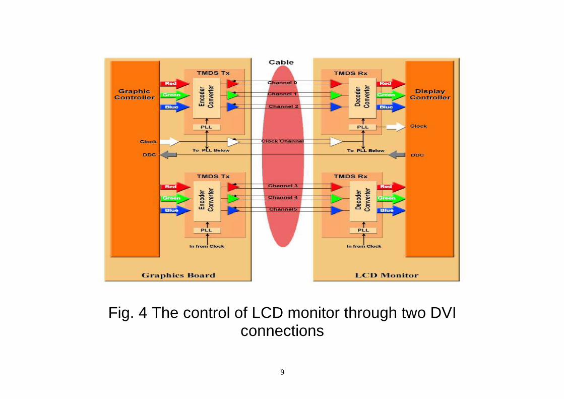
Fig. 4 The control of LCD monitor through two DVI connections
10
• Comments to Fig. 3 and Fig. 4 One or two channels are active, depending on the demanded resolution (for certain value of resolution, a certain speed of communication between graphics adapter and monitor) DVI terminology – each connection consists of channels. Channel – information about one of color components (R, G, B). PLL – Phase Locked Loop – synchro clock is generated in LCD monitor internally. PLL has the ability to become synchronized by a frequency delivered from the outside.
• What is DDC? DDC - Display Data Channel:
11
The channel through which data representing its specification (stored in monitor) can be transported to graphic adapter. It is stored in PROM (programmable read-only memory) or EEPROM (electrically erasable PROM). Through DDC the computer recognizes what type of monitor is connected to the computer. I2C Communication protocol –– it allows to connect more elements of bus master type. In this application – only one bus master – graphic adapter. Data format – EDID (Extended Display Information Data) defined by Video Electronics Standards Association (VESA) standard.
12
EDID contains the producer, monitor type, the type of luminescent layer, filter type, timing of monitor, screen size, …. EDID 1.0 version - 1994, 1.1 version - 1996, 1.2 version, 1.3 version -2000. EDID size - 128 B, EDID 2.0 version contains 256 B. EDID and I2C combination is called DDC version 2 or DDC2.
• How the monitor type was recognized in the past? One possibility – one, two or three pins on connector were grounded – not standardized.
• EDID structure is available at: http://en.wikipedia.org/wiki/EDID
13
• In the protocol, TMDS (Transition Minimized Differential Signalling) is used. In the past, LVDS (Low Voltage Differential Signaling) was used in serial protocols.
• TMDS and LVDS comparison LVDS – used in notebooks for internal connections. For external connections it cannot be used because of possible length: LVDS – limited cable length, TMDS – cable up to the length of 15 m. With LVDS the resolution of 2048 x 1536 pixels can be gained, resolution with TMDS can be much higher (two channels). LVDS – different modes, different number of channels TMDS – two channels, the second channel is activated at the speed of 165 MHz.
14
• TMDS technique (Transition Minimized Differential Signaling) The technique used for DVI monitors Features: Minimized number of 1 → 0, 0→ 1 transitions. Differential signal – higher noise immunity. For each color two wires are used. One channel – 6 wires, two wires for each color. Two channels are available – the second channel for frequencies higher than 165 MHz.
15
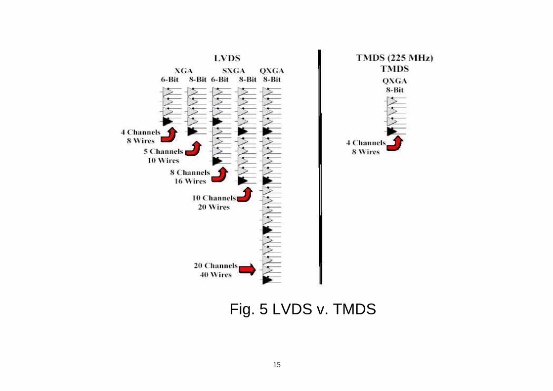
Fig. 5 LVDS v. TMDS
16
• Comments on Fig. 5 LVDS – if higher resolution (higher bandwidth) is required then higher number of connections is required. TMDS – nothing like this is needed (the concept of complete link is used).
Differential signalling
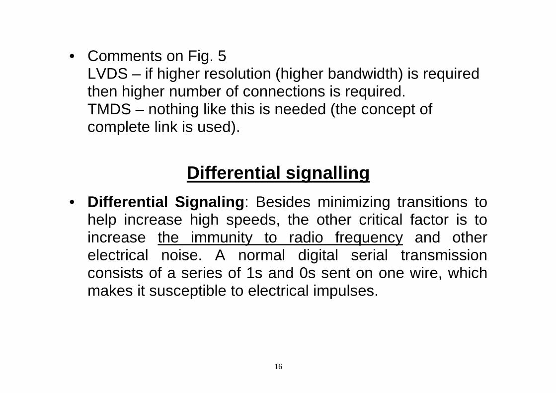
• Differential Signaling : Besides minimizing transitions to help increase high speeds, the other critical factor is to increase the immunity to radio frequency and other electrical noise. A normal digital serial transmission consists of a series of 1s and 0s sent on one wire, which makes it susceptible to electrical impulses.
17
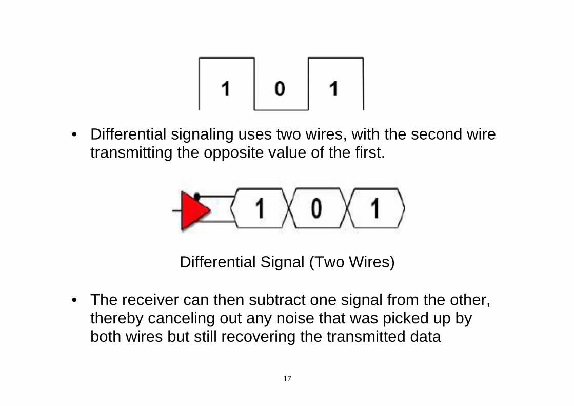
• Differential signaling uses two wires, with the second wire
transmitting the opposite value of the first.
Differential Signal (Two Wires)
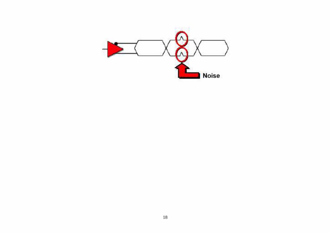
• The receiver can then subtract one signal from the other,
thereby canceling out any noise that was picked up by both wires but still recovering the transmitted data
18
19
The problem of increasing the resolution • DVI was developed with the perspective of increasing the
resolution (bandwidth). • One DVI channel – for 1600 x 1200 resolution, vertical
synchronization of 60 Hz. For higher resolution, e. g. 1920 x 1080 problems can appear.
• The solution: additional connection or utilising „reduced blanking“ (the reduction of not displayed area).
• How is „reduced blanking“ performed? In CRT monitor, the screen becomes dark during the “reverse runs” of the electron beam when the beam returns to the starting point of the scan line (horizontal sync) or to the beginning of the first scan line (vertical sync).
20
LCD monitor – no “reverse run” is needed, it means we can reduce the horizontal sync frequency and still have sufficient image quality (in fact we reduce the number of screens displayed in one second).
21
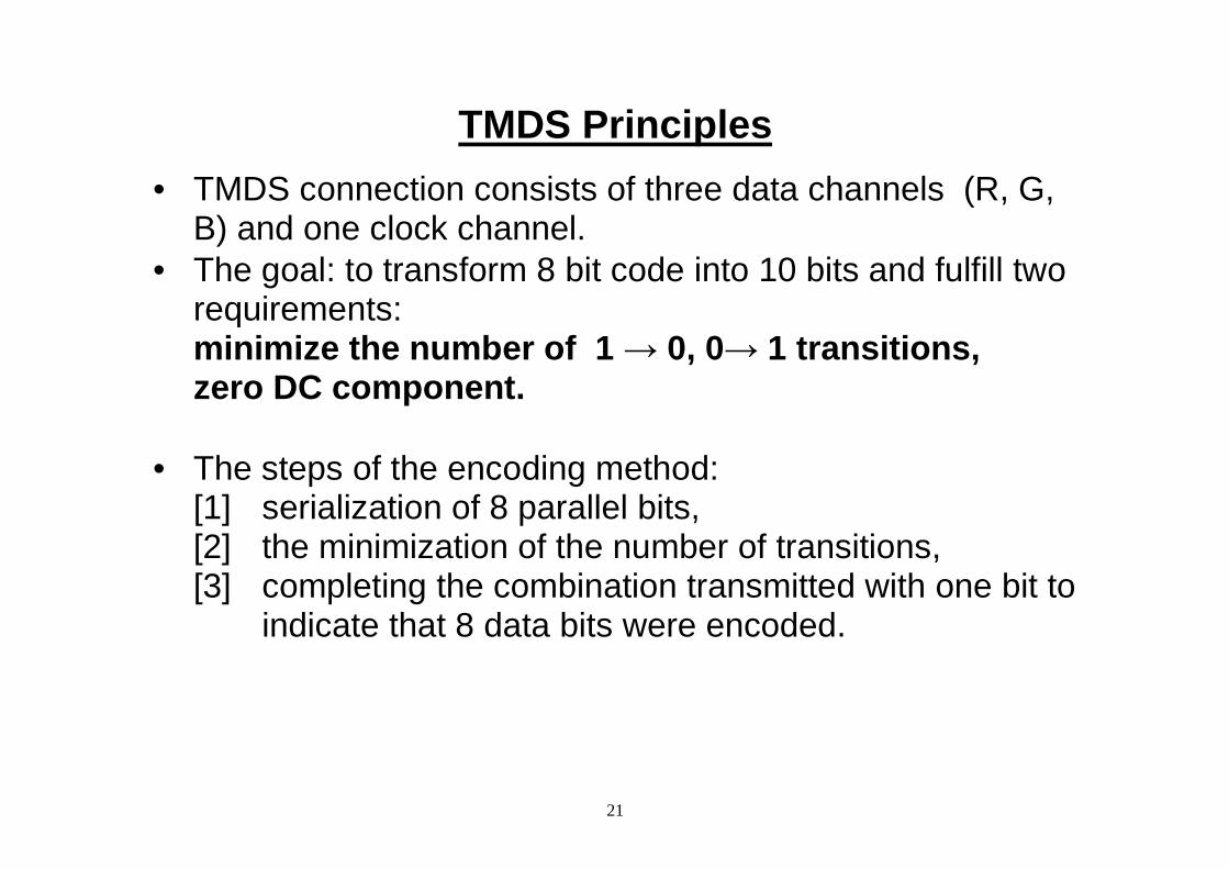
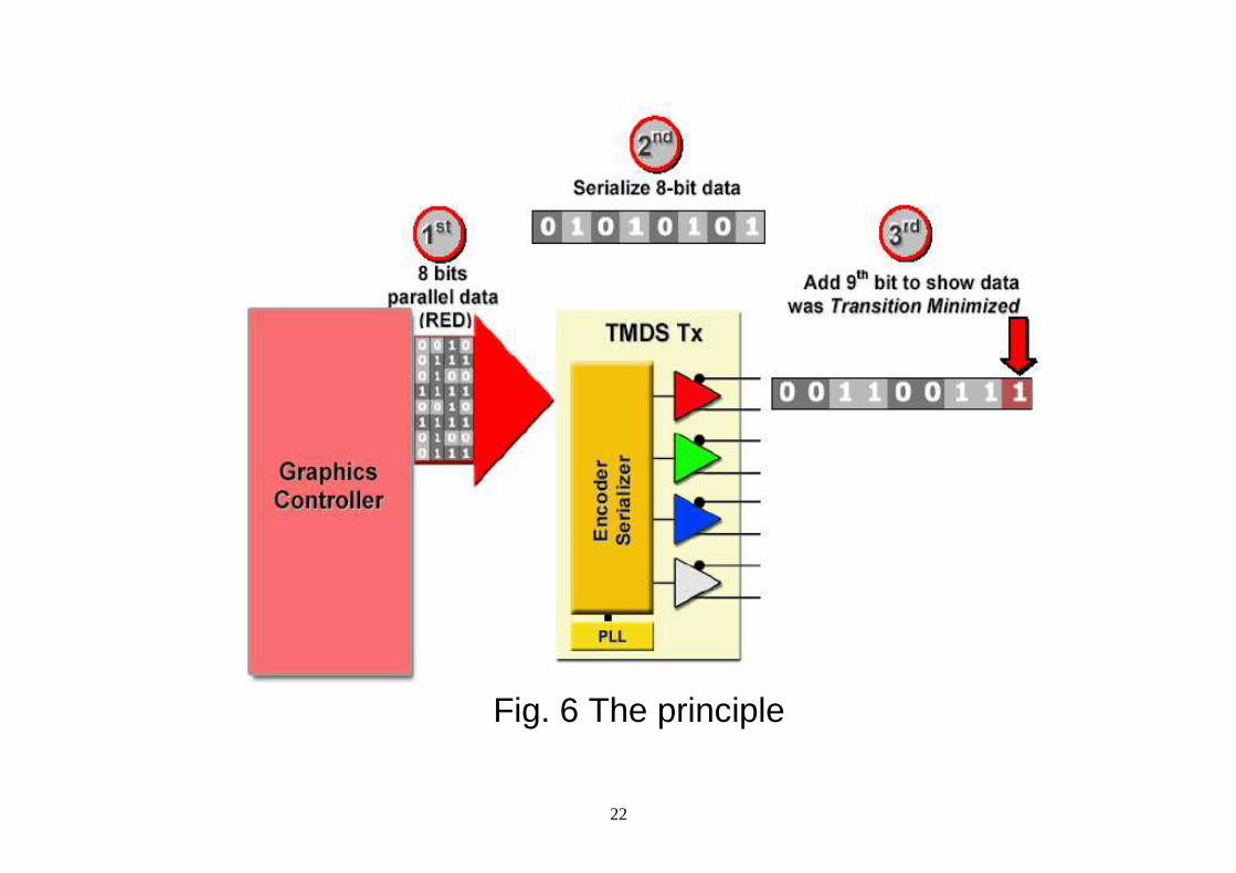
TMDS Principles
• TMDS connection consists of three data channels (R, G, B) and one clock channel.
• The goal: to transform 8 bit code into 10 bits and fulfill two requirements: minimize the number of 1 → 0, 0→ 1 transitions, zero DC component.
• The steps of the encoding method: [1] serialization of 8 parallel bits, [2] the minimization of the number of transitions, [3] completing the combination transmitted with one bit to
indicate that 8 data bits were encoded.
22
Fig. 6 The principle
23
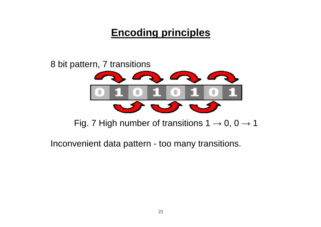
Encoding principles 8 bit pattern, 7 transitions
Fig. 7 High number of transitions 1 → 0, 0 → 1
Inconvenient data pattern - too many transitions.
24
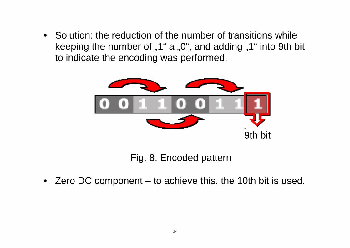
• Solution: the reduction of the number of transitions while keeping the number of „1“ a „0“, and adding „1“ into 9th bit to indicate the encoding was performed.
9th bit
Fig. 8. Encoded pattern
• Zero DC component – to achieve this, the 10th bit is used.
25
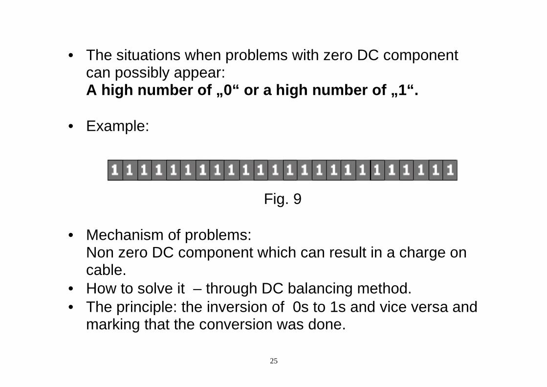
• The situations when problems with zero DC component can possibly appear: A high number of „0“ or a high number of „1“.
• Example:
Fig. 9
• Mechanism of problems:
Non zero DC component which can result in a charge on cable.
• How to solve it – through DC balancing method. • The principle: the inversion of 0s to 1s and vice versa and
marking that the conversion was done.
26
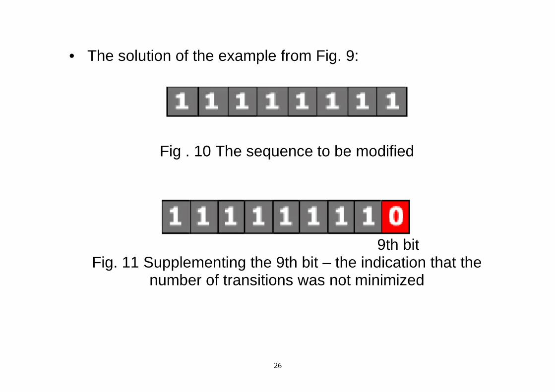
• The solution of the example from Fig. 9:
Fig . 10 The sequence to be modified
9th bit
Fig. 11 Supplementing the 9th bit – the indication that the number of transitions was not minimized
27
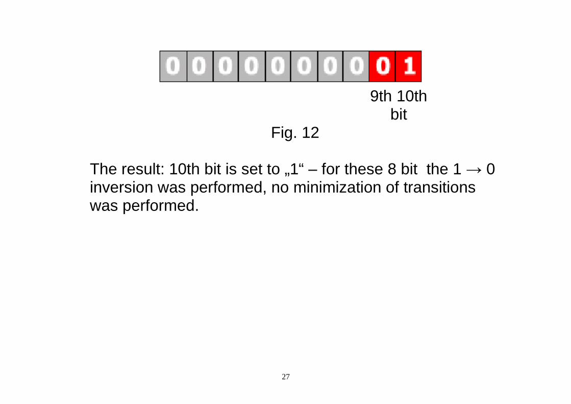
9th 10th
bit Fig. 12
The result: 10th bit is set to „1“ – for these 8 bit the 1 → 0 inversion was performed, no minimization of transitions was performed.
28
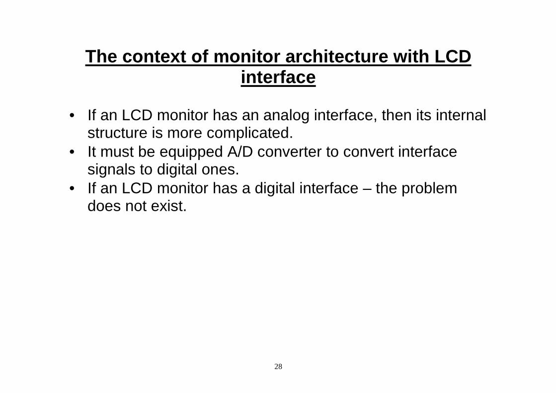
The context of monitor architecture with LCD interface
• If an LCD monitor has an analog interface, then its internal
structure is more complicated. • It must be equipped A/D converter to convert interface
signals to digital ones. • If an LCD monitor has a digital interface – the problem
does not exist.
29
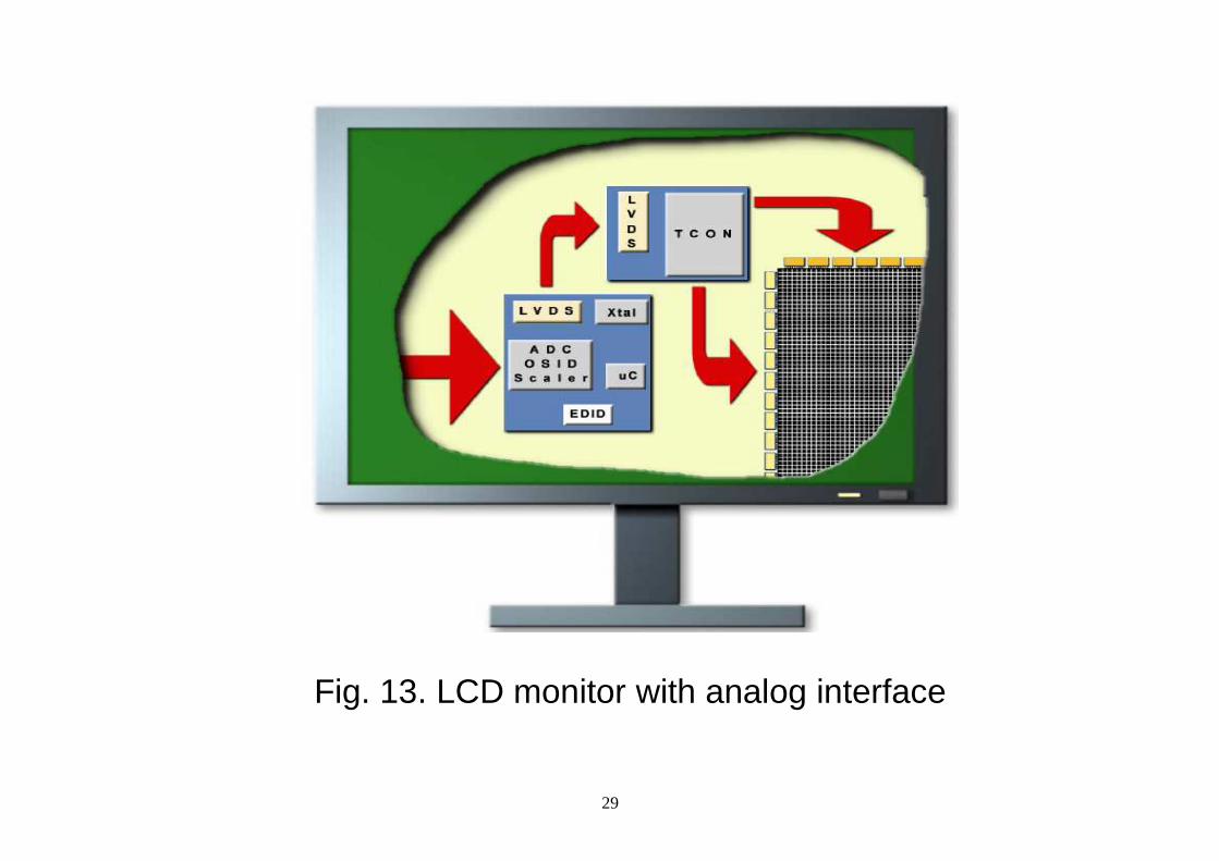
Fig. 13. LCD monitor with analog interface
30
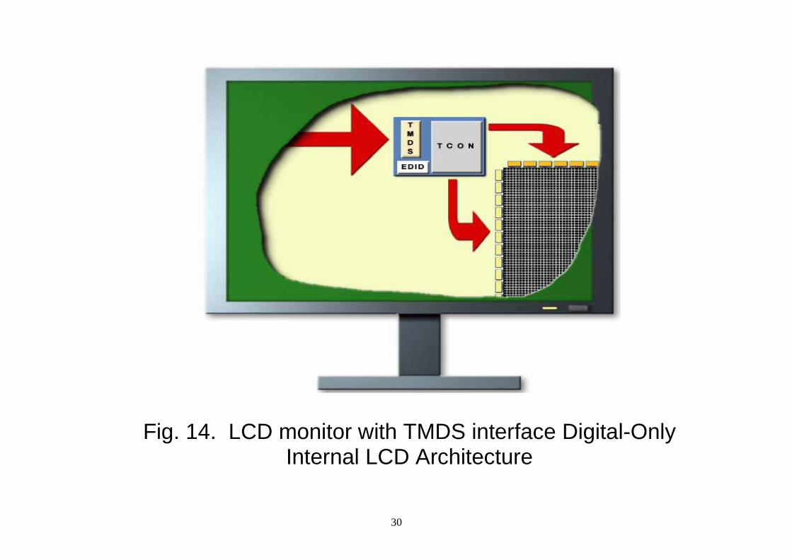
Fig. 14. LCD monitor with TMDS interface Digital-Only Internal LCD Architecture
31
DVI Technical discussion • The data format used by DVI is based on the PanelLink
serial format devised by the semiconductor manufacturer Silicon Image Inc.
• This uses Transition Minimized Differential Signaling (TMDS).
• A single DVI link consists of four twisted pairs of wire (red, green, blue, and clock) to transmit 24 bits per pixel.
• The timing of the signal almost exactly matches that of an analog video signal.
• The picture is transmitted line by line with blanking intervals between each line and each frame, and without packetization.
• No compression is used and there is no support for only transmitting changed parts of the image.
32
• This means that the whole frame is constantly re-transmitted.
• The specification (see below for link) does, however, include a paragraph on "Conversion to Selective Refresh" (under 1.2.2), suggesting this feature for future devices.
• With a single DVI link, the largest resolution possible at 60Hz is 2.3 megapixels.
• The DVI connector therefore has provision for a second link, containing another set of red, green, and blue twisted pairs.
• When higher bandwidth is required than it is possible with a single link, the second link is enabled, and alternate pixels may be transmitted on each, allowing resolutions up to 4 megapixels at 60Hz.
33
• The DVI specification mandates a fixed single link cutoff point of 165 MHz, where all display modes that require less than this must use single link mode, and all those that require more must switch to dual link mode.
• When both links are in use, the pixel rate on each may exceed 165 MHz.
• The second link can also be used when more than 24 bits per pixel is required, in which case it carries the least significant bits.
• Like modern analog VGA connectors, the DVI connector includes pins for the display data channel, version 2 (DDC 2) that allows the graphics adapter to read the monitor's extended display identification data (EDID).
34
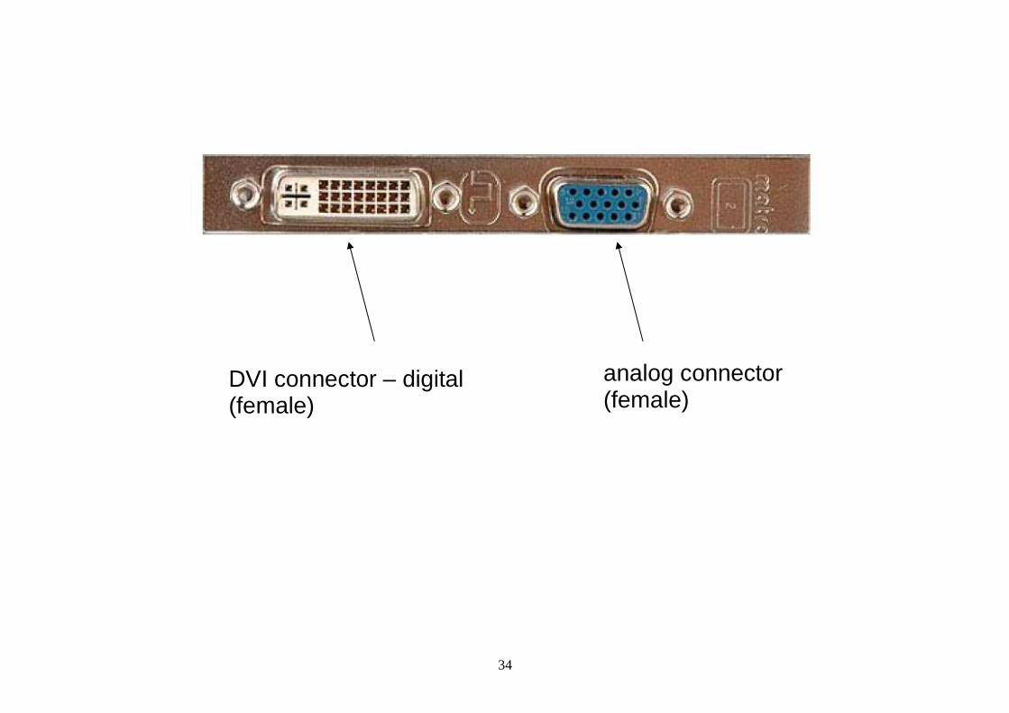
analog connector (female)
DVI connector – digital (female)
35
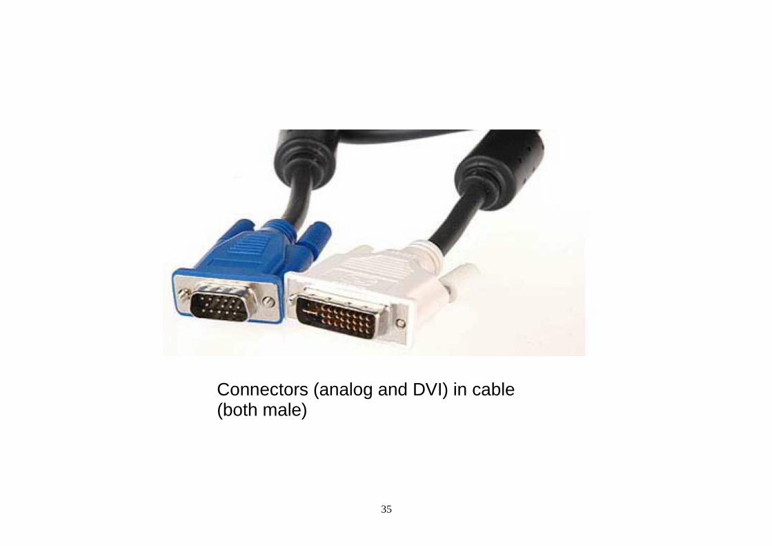
Connectors (analog and DVI) in cable (both male)