Embed Size (px)
Citation preview
International Journal of Advanced Mechanical Engineering.
ISSN 2250-3234 Volume 8, Number 1 (2018), pp. 13-24
© Research India Publications
http://www.ripublication.com
Dynamic Behavior of a Structure using MR Fluid
Damper
G. Sailaja 1 N. Seetharamaiah 2 and Maganti Janardhana 3
1 Assistant Professor, Dept. of Mech. Engg., MJCET, Road No.3, Banjara hills, Hyderabad-34, India.
(Corresponding author) 2 Professor, Dept. of Mech. Engg., MJCET. Road No.3, Banjara hills,
Hyderabad-34, India.
3 Professor, Dept. of Civil Engg., JNTU Hyderabad, India.
Abstract
A Magnetorheological fluid (MRF) damper offers an effective solution for
semi-active vibration control in structural vibrations. The MRF damper
performance depends significantly on the electromagnetic circuit which is
incorporated into it. The force which is developed by MR fluid damper is
greatly influenced by the magnetic flux density induced in the fluid flow gap.
In the fields of Civil and Mechanical Engineering, Magnetorheological fluid
(MRF) damper based semi-active systems offer protection to structures
subjected to mechanical vibrations and also lateral loads due to wind and
earthquake forces. In the present work, synthesis of MR fluids is discussed
and the operating principle of the MRF damper is explained. Finally, the
dynamic behavior of a portal frame subjected to different forcing frequencies
using MRF dampers with three different types of MR fluids is studied. It is
observed that the dampers with MRF1 (having 40% magnetic particles) is
performing in a better way when compared with another dampers with MRF
(commercially available) and MRF2 (having 36% magnetic particles).
Keywords: MR Fluids, MRF1, MRF2, MR Fluid Damper, Structural
vibrations.
1. INTRODUCTION:
Magnetorheological Fluid Damper is one of the smart fluid dampers which can be
used to suppress the vibrations and to improve the performance. Out of many dampers
that are being used, MR fluid damper was found to be more effective than the
14 G. Sailaja, N. Seetharamaiah and Maganti Janardhana
conventional viscous damper [1]. Magnetorheological (MR) fluid was first reported by
Rabinow [2] in the year 1948 and he concluded that MR fluids are magnetic field
controllable fluids. When the fluid is exposed to an external magnetic field, this MR
fluid instantaneously changes from a viscous fluid to a semisolid, and forms a chain
like structure, depending on the directions of the magnetic field, with a yield strength
which is controllable. MR fluids can operate at temperatures ranging from 40 ºC to
150 ºC, with only slight variation in Yield stress [3]. The main focus of this
investigation is to study the performance of the MR Fluid (MRF) dampers on a
structure which is vibrated with different speeds. When an electric field is applied to
the MR fluid, the fluid becomes a semisolid and behaves as a viscoelastic spring with
non-linear vibration characteristics. This transition is reversible and can be achieved
in few milliseconds. In the present paper, three types of fluids i.e., MRF
(commercially available), MRF1 (having 40% magnetic particles) and MRF2 (having
36% magnetic particles) fluids (which were synthesized) to use in both single and
double stage coil MRF dampers. The test specimen was tested with commercially
available Magnetorheological fluid (MRF) and also the Preparation of the fluids
MRF1 and MRF2 is described in the following section. These dampers are attached to
a single bay four storeyed portal frame made up of aluminium and having each bay
width of 0.3048m and each storey height of 0.3048m. The portal frame is subjected to
forced vibrations of three different frequencies of 1300 rpm, 1350 rpm, and 1440 rpm.
Then the output frequencies of the structure (portal frame) attached with MRF, MRF1
and MRF2 dampers alternately for different current inputs (0 to 2 A) are recorded and
compared.
2. MR FLUID AND ITS COMPONENTS:
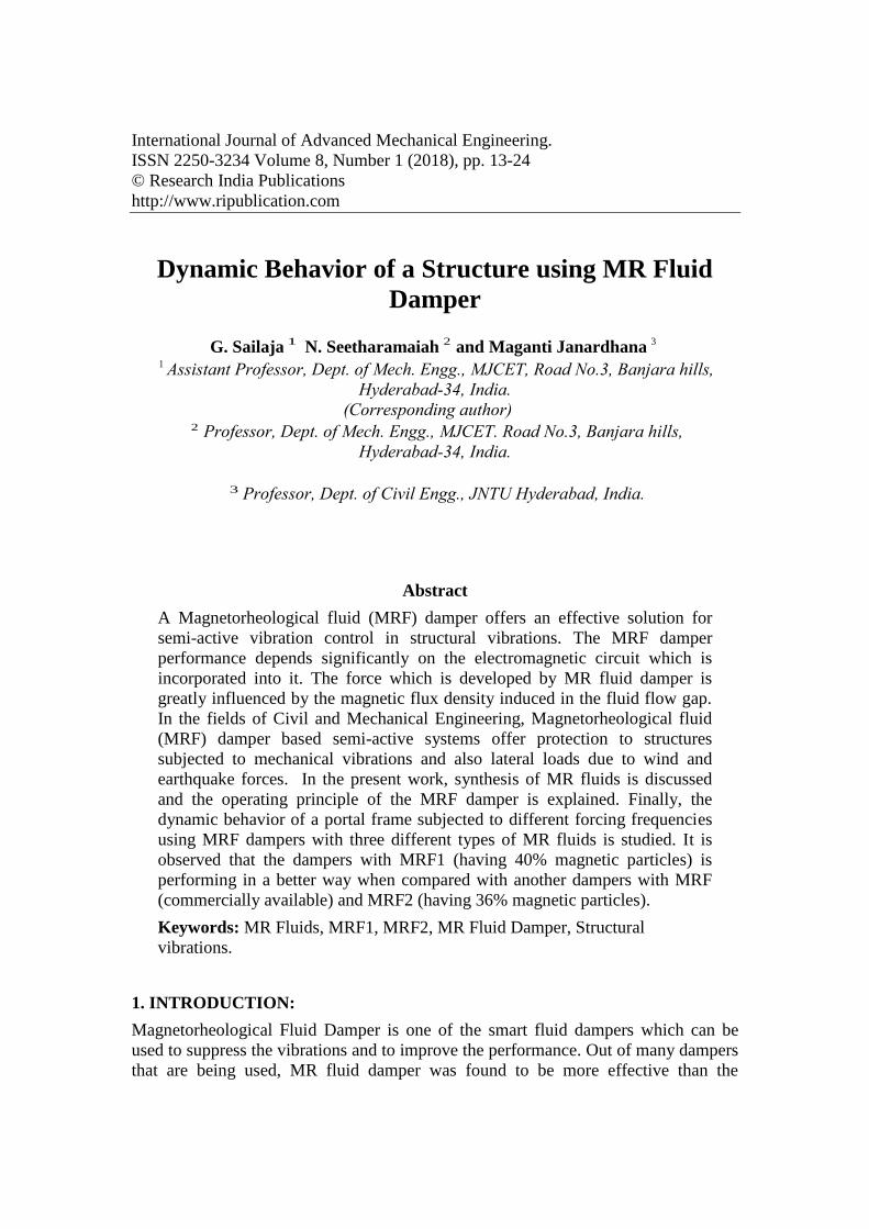
MR fluids are suspensions of micron-sized magnetisable particles in a carrier fluid.
They mainly consist of the following three components: magnetisable particles,
carrier fluid, and some additional additives. These magnetisable particles induce
polarization by application of an external magnetic field, which results in the
Magnetorheological effect of the MR fluids. This is illustrated in the Fig.1.
Fig. 1: Activation of MR Fluid (Courtesy: www.iopscience.iop.org)
Dynamic Behavior of a Structure using MR Fluid Damper 15
In the absence of an applied magnetic field, the particles in MR fluid disperse
randomly in a carrier fluid. MR fluid flows freely through the working gap between
the fixed outer cylinder and rotor. The dynamic behavior of MR fluids has been
developed through annular duct using Navier-Stokes equation based on the Herschel-
Bulkley and Bingham models for non-Newtonian fluid flows [4].
The composition of MR fluid includes a carrier fluid, magnetic-responsive particles,
and hydrophobic organ clay. The hydrophobic organ clay is present as an anti-settling
agent, which provides soft sediment once the magnetic particles settle out. The
compositions form a thixotropic network that is effective at minimizing particles
settling and also in lowering the shear forces required to re-suspend the particles once
they settle. The composition described herein have a relatively low viscosity, do not
settle easily, and can be easier to re-disperse than conventional Magnetorheological
fluids, including those which contain conventional anti settling agents such as silicon
dioxide or silica. The composition typically has atleast 10 % less sediment hardness
than comparative fluids that include silica rather than the hydrophobic organ clay,
where the test involves repeated heating and cooling circles over a two weeks period.
The compositions may cause 10 % less device wear than comparative fluids that
include silica rather than the hydrophobic organ clay[5]. Any solid that is known to
exhibit magnetorheological activity can be used as a suspension within the carrier
fluid. Examples of suitable magnetizable particles include iron, iron alloys (such as
those including aluminum, silicon, cobalt, nickel, vanadium, molybdenum, chromium,
tungsten, manganese and/or copper), iron oxides (including Fe2O3 and Fe3O4), iron
nitride, iron carbide, carbonyl iron, nickel, cobalt, chromium dioxide, stainless steel
and silicon steel. A preferred magnetic responsive particulate is carbonyl iron,
preferably, reduced carbonyl iron.
3. SYNTHESIS OF MR FLUID:
The materials as mentioned above plays a vital role as the properties of the MR fluid
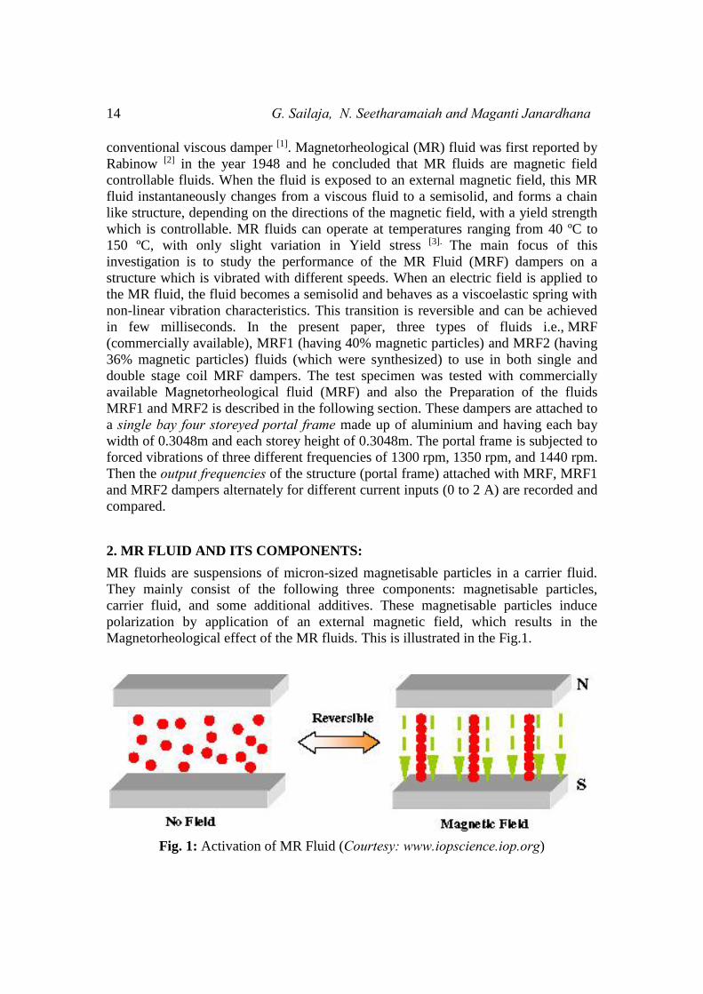
depend on these concentrations. Fig. 2 shows the gravitational settling of carbonyl
iron particles. The properties of the MR fluid depend on these concentrations. The
properties are subject to change if different concentrations of carrier fluid, magnetic
particles and additives are used. For the present study, two MR fluids were prepared
using two different concentrations (by volume) of magnetic particles. The first
concentration of MR fluid incorporates 40% by volume of magnetic particles. This is
termed as MRF1. These are carbon based iron particles and are called as Carbonyl
iron particles. They were mixed with the carrier fluid only and kept undisturbed for a
period of five days to observe the gravitational settling. It was observed that the
quantity of particles settled was approximately 120 ml in a period of 5 days from the
total height of the fluid column as shown in the Fig. 2.
16 G. Sailaja, N. Seetharamaiah and Maganti Janardhana
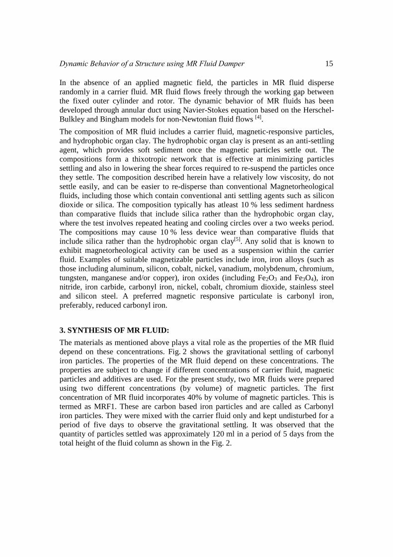
Fig. 2: Gravitational settling of carbonyl iron particles Fig. 3: Synthesized MRF1
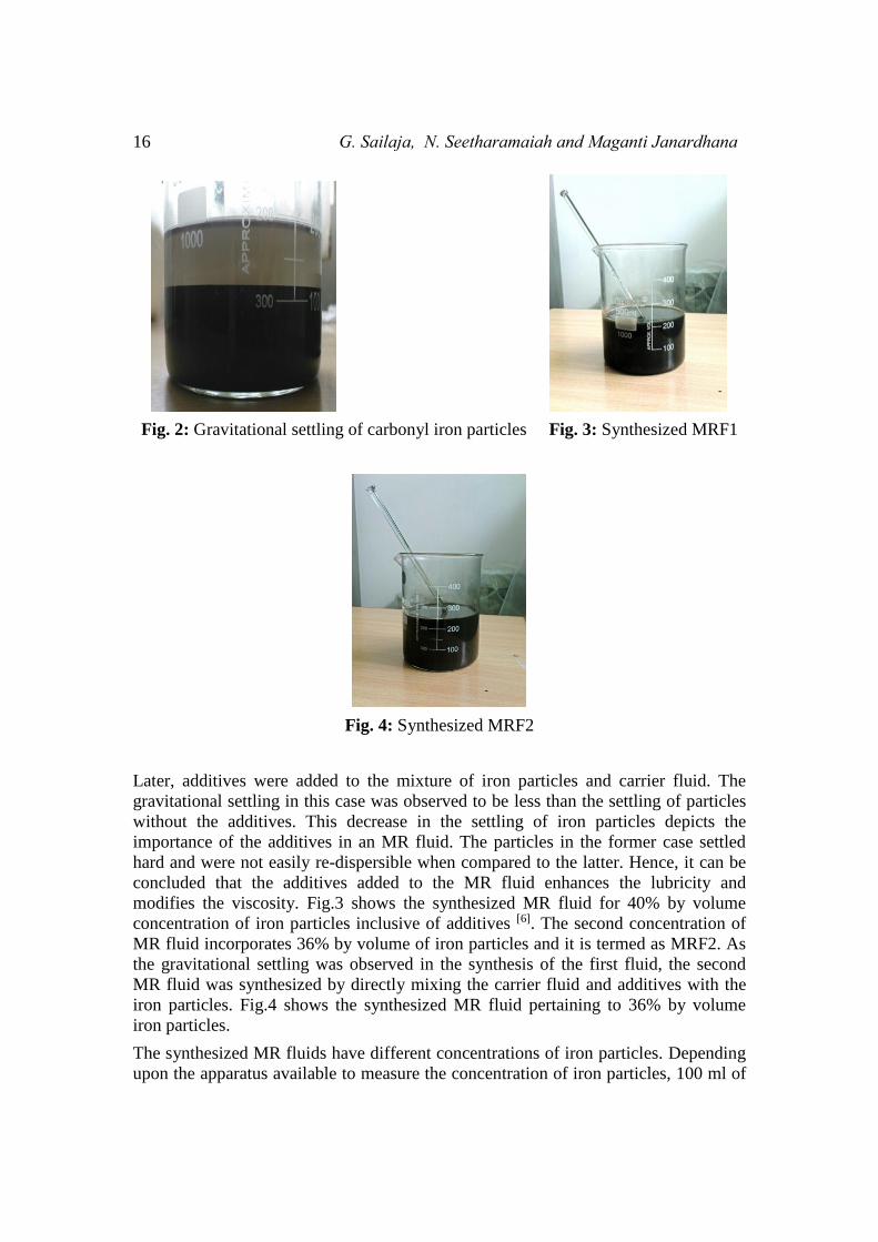
Fig. 4: Synthesized MRF2
Later, additives were added to the mixture of iron particles and carrier fluid. The
gravitational settling in this case was observed to be less than the settling of particles
without the additives. This decrease in the settling of iron particles depicts the
importance of the additives in an MR fluid. The particles in the former case settled
hard and were not easily re-dispersible when compared to the latter. Hence, it can be
concluded that the additives added to the MR fluid enhances the lubricity and
modifies the viscosity. Fig.3 shows the synthesized MR fluid for 40% by volume
concentration of iron particles inclusive of additives [6]. The second concentration of
MR fluid incorporates 36% by volume of iron particles and it is termed as MRF2. As
the gravitational settling was observed in the synthesis of the first fluid, the second
MR fluid was synthesized by directly mixing the carrier fluid and additives with the
iron particles. Fig.4 shows the synthesized MR fluid pertaining to 36% by volume
iron particles.
The synthesized MR fluids have different concentrations of iron particles. Depending
upon the apparatus available to measure the concentration of iron particles, 100 ml of
Dynamic Behavior of a Structure using MR Fluid Damper 17
particles were measured while synthesizing both fluids and appropriate concentration
of carrier fluid was added, to both MRF1 and MRF2, in order to balance the
proportion of 40% iron particles and 60% carrier fluid for the MRF1 and 40% iron
particles and 60% carrier fluid for the MRF2. The MR fluid with higher concentration
of iron particles, i.e., 40% is relatively more porous than the MR fluid with lower
concentration of iron particles, i.e., 36%. This can be observed from Figs 3 and 4
where the final quantity of the mixture of MR fluid is different in both the cases. The
quantity of the MR fluid with 40% by volume of iron particles is less when compared
to the quantity of the MR fluid with 36% by volume of iron particles even though the
total quantity of the concentration of iron particles and carrier fluid was same. This is
due to the presence of large number of pores for MR fluid with 40% by volume of
iron particles. Both the fluids i.e., MRF1 and MRF2 are used in the dampers for
observing the dynamic behavior of a single bay four storeyed portal frame made up of
aluminium and the results of MRF1 and MRF2 are compared. It was observed that
stress developed in the damper is well within the permissible stress limit of the
material when pressure analysis was performed on the MR damper [7].
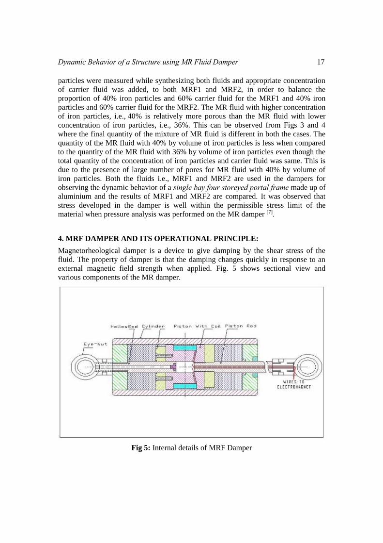
4. MRF DAMPER AND ITS OPERATIONAL PRINCIPLE:
Magnetorheological damper is a device to give damping by the shear stress of the
fluid. The property of damper is that the damping changes quickly in response to an
external magnetic field strength when applied. Fig. 5 shows sectional view and
various components of the MR damper.
Fig 5: Internal details of MRF Damper
18 G. Sailaja, N. Seetharamaiah and Maganti Janardhana
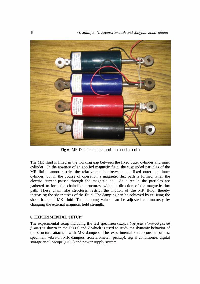
Fig 6: MR Dampers (single coil and double coil)
The MR fluid is filled in the working gap between the fixed outer cylinder and inner
cylinder. In the absence of an applied magnetic field, the suspended particles of the
MR fluid cannot restrict the relative motion between the fixed outer and inner
cylinder, but in the course of operation a magnetic flux path is formed when the
electric current passes through the magnetic coil. As a result, the particles are
gathered to form the chain-like structures, with the direction of the magnetic flux
path. These chain like structures restrict the motion of the MR fluid, thereby
increasing the shear stress of the fluid. The damping can be achieved by utilizing the
shear force of MR fluid. The damping values can be adjusted continuously by
changing the external magnetic field strength.
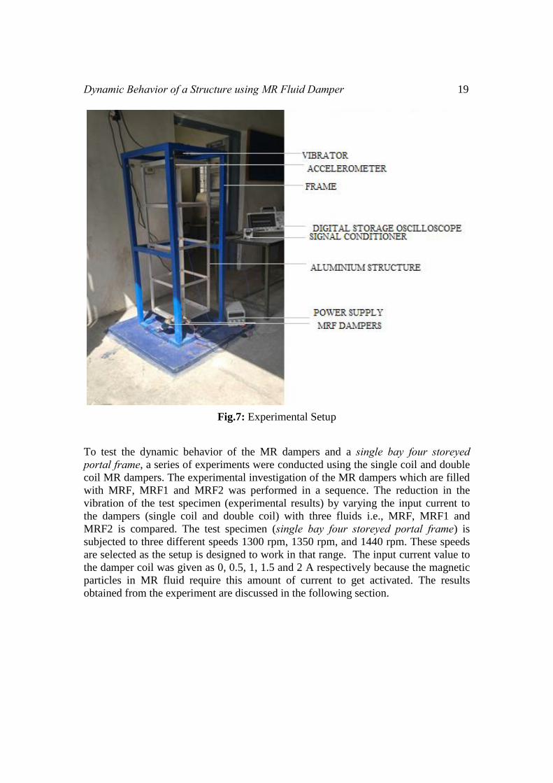
6. EXPERIMENTAL SETUP:
The experimental setup including the test specimen (single bay four storeyed portal frame) is shown in the Figs 6 and 7 which is used to study the dynamic behavior of
the structure attached with MR dampers. The experimental setup consists of test
specimen, vibrator, MR dampers, accelerometer (pickup), signal conditioner, digital
storage oscilloscope (DSO) and power supply system.
Dynamic Behavior of a Structure using MR Fluid Damper 19
Fig.7: Experimental Setup
To test the dynamic behavior of the MR dampers and a single bay four storeyed portal frame, a series of experiments were conducted using the single coil and double
coil MR dampers. The experimental investigation of the MR dampers which are filled
with MRF, MRF1 and MRF2 was performed in a sequence. The reduction in the
vibration of the test specimen (experimental results) by varying the input current to
the dampers (single coil and double coil) with three fluids i.e., MRF, MRF1 and
MRF2 is compared. The test specimen (single bay four storeyed portal frame) is
subjected to three different speeds 1300 rpm, 1350 rpm, and 1440 rpm. These speeds
are selected as the setup is designed to work in that range. The input current value to
the damper coil was given as 0, 0.5, 1, 1.5 and 2 A respectively because the magnetic
particles in MR fluid require this amount of current to get activated. The results
obtained from the experiment are discussed in the following section.
20 G. Sailaja, N. Seetharamaiah and Maganti Janardhana
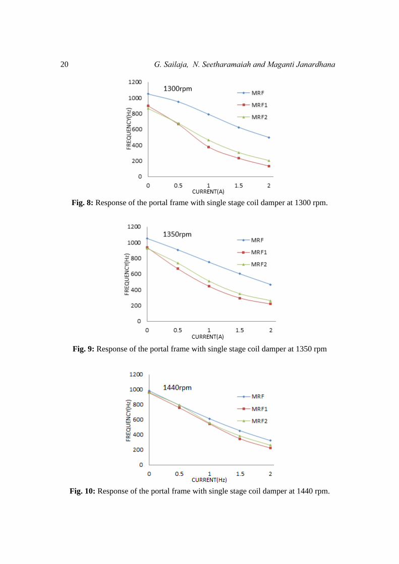
Fig. 8: Response of the portal frame with single stage coil damper at 1300 rpm.
Fig. 9: Response of the portal frame with single stage coil damper at 1350 rpm
Fig. 10: Response of the portal frame with single stage coil damper at 1440 rpm.
Dynamic Behavior of a Structure using MR Fluid Damper 21
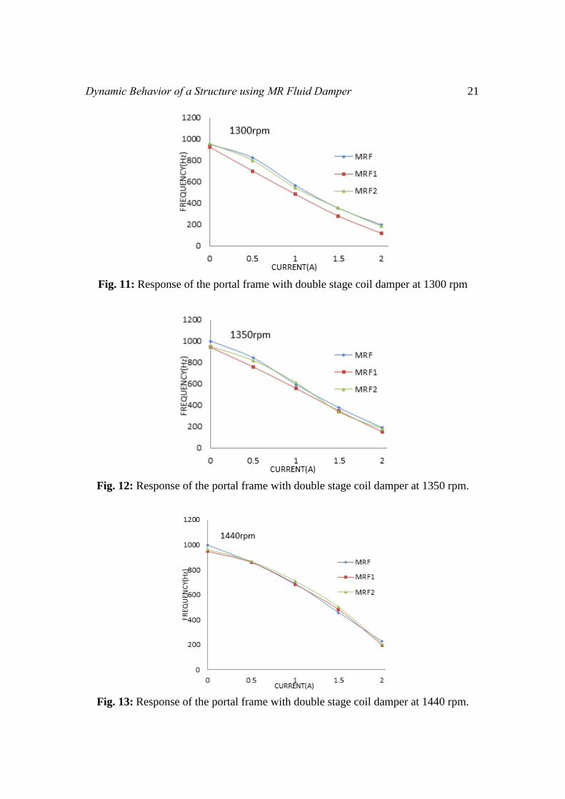
Fig. 11: Response of the portal frame with double stage coil damper at 1300 rpm
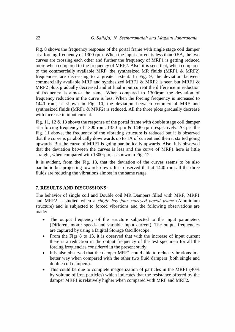
Fig. 12: Response of the portal frame with double stage coil damper at 1350 rpm.
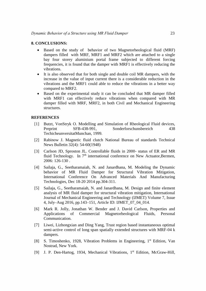
Fig. 13: Response of the portal frame with double stage coil damper at 1440 rpm.
22 G. Sailaja, N. Seetharamaiah and Maganti Janardhana
Fig. 8 shows the frequency response of the portal frame with single stage coil damper
at a forcing frequency of 1300 rpm. When the input current is less than 0.5A, the two
curves are crossing each other and further the frequency of MRF1 is getting reduced
more when compared to the frequency of MRF2. Also, it is seen that, when compared
to the commercially available MRF, the synthesized MR fluids (MRF1 & MRF2)
frequencies are decreasing to a greater extent. In Fig. 9, the deviation between
commercially available MRF and synthesized MRF1 & MRF2 is seen but MRF1 &
MRF2 plots gradually decreased and at final input current the difference in reduction
of frequency is almost the same. When compared to 1300rpm the deviation of
frequency reduction in the curve is less. When the forcing frequency is increased to
1440 rpm, as shown in Fig. 10, the deviation between commercial MRF and
synthesized fluids (MRF1 & MRF2) is reduced. All the three plots gradually decrease
with increase in input current.
Fig. 11, 12 & 13 shows the response of the portal frame with double stage coil damper
at a forcing frequency of 1300 rpm, 1350 rpm & 1440 rpm respectively. As per the
Fig. 11 above, the frequency of the vibrating structure is reduced but it is observed
that the curve is parabolically downwards up to 1A of current and then it started going
upwards. But the curve of MRF1 is going parabolically upwards. Also, it is observed
that the deviation between the curves is less and the curve of MRF1 here is little
straight, when compared with 1300rpm, as shown in Fig. 12.
It is evident, from the Fig. 13, that the deviation of the curves seems to be also
parabolic but projecting towards down. It is observed that at 1440 rpm all the three
fluids are reducing the vibrations almost in the same range.
7. RESULTS AND DISCUSSIONS:
The behavior of single coil and Double coil MR Dampers filled with MRF, MRF1
and MRF2 is studied when a single bay four storeyed portal frame (Aluminium
structure) and is subjected to forced vibrations and the following observations are
made:
The output frequency of the structure subjected to the input parameters
(Different motor speeds and variable input current). The output frequencies
are captured by using a Digital Storage Oscilloscope.
From the Figs 8 to 13, it is observed that with the increase of input current
there is a reduction in the output frequency of the test specimen for all the
forcing frequencies considered in the present study.
It is also observed that the damper MRF1 could able to reduce vibrations in a
better way when compared with the other two fluid dampers (both single and
double coil dampers).
This could be due to complete magnetization of particles in the MRF1 (40%
by volume of iron particles) which indicates that the resistance offered by the
damper MRF1 is relatively higher when compared with MRF and MRF2.
Dynamic Behavior of a Structure using MR Fluid Damper 23
8. CONCLUSIONS:
Based on the study of behavior of two Magnetorheological fluid (MRF)
dampers filled with MRF, MRF1 and MRF2 which are attached to a single
bay four storey aluminium portal frame subjected to different forcing
frequencies, it is found that the damper with MRF1 is effectively reducing the
vibrations.
It is also observed that for both single and double coil MR dampers, with the
increase in the value of input current there is a considerable reduction in the
vibrations and the MRF1 could able to reduce the vibrations in a better way
compared to MRF2.
Based on the experimental study it can be concluded that MR damper filled
with MRF1 can effectively reduce vibrations when compared with MR
damper filled with MRF, MRF2, in both Civil and Mechanical Engineering
structures.
REFERENCES
[1] Butzt, VonStryk O. Modelling and Simulation of Rheological Fluid devices,
Preprint SFB-438-991, Sonderforschunsbereich 438
TechicheunversitatMunchan, 1999.
[2] Rabinow J. Magnetic fluid clutch National Bureau of standards Technical
News Bulletin 32(4): 54-60(1948)
[3] Carlson JD, Sproston JL. Controllable fluids in 2000- status of ER and MR
fluid Technology. In 7th international conference on New Actuator,Bermen,
2006: 126-130 .
[4] Sailaja, G., Seetharamaiah, N. and Janardhana, M. Modeling the Dynamic
behavior of MR Fluid Damper for Structural Vibration Mitigation,
International Conference On Advanced Materials And Manufacturing
Technologies, Dec 18-20 2014 pp.304-311.
[5] Sailaja, G., Seetharamaiah, N. and Janardhana, M. Design and finite element
analysis of MR fluid damper for structural vibration mitigation, International
Journal of Mechanical Engineering and Technology (IJMET) Volume 7, Issue
4, July–Aug 2016, pp.143–151, Article ID: IJMET_07_04_014.
[6] Mark R. Jolly, Jonathan W. Bender and J. David Carlson, Properties and
Applications of Commercial Magnetorheological Fluids, Personal
Communication.
[7] Liwei, Lizhongxian and Ding Yang, Trust region based instantaneous optimal
semi-active control of long span spatially extended structures with MRF-04 k
dampers.
[8] S. Timoshenko, 1928, Vibration Problems in Engineering, 1st Edition, Van
Nostrad, New York.
[9] J. P. Den-Hartog, 1934, Mechanical Vibrations, 1st Edition, McGraw-Hill,
24 G. Sailaja, N. Seetharamaiah and Maganti Janardhana
New York.
[10] Neil David Sims, 1999, Modelling and Control of an Electrorheological Long-
Stroke Vibration Damper, Ph.D.Thesis, Department of Mechanical
Engineering, The University of Sheffield, UK.
[11] Guangqiang Yang, 2001, Large-scale Magnetorheological Fluid Damper for
Vibration Mitigation: Modeling, Testing and Control, Ph.D. Thesis,
Department of Civil Engineering and Geological Sciences, University of Notre
Dame, Indiana, USA.