Embed Size (px)
Citation preview
200
D Y N A M I C B E H A V I O U R O F A S U B S U R F A C E T U B U L A R S T R U C T U R E
E i i c h i K u r i b a y a s h i * , T o s h i o I w a s a k i * * a n d K a z u h i k o K a w a s h i m a * * *
ABSTRACT During the last eighty years of submerged tunnel construction in
the civil engineering field, the problem of aseismic design has been discussed. In this paper a new aseismic design criterion, seismic deformation analysis, is proposed based on wave propagation principles avoiding force method principles of design: so-called seismic coefficient method.
Ground subsurface properties such as density, elastic moduli and thickness effect the natural period of the subground, and response displacements of the subsurface at specific sites are obtained by the input accelerations of the base rock and damping characteristics.
Deformations and working stresses of the tunnel structural systems are obtained by the tunnel being assumed as an embedded beam or rod supported elastically by the ground and sweeping over the system values of the wave length such as provide maximum stresses at each point of the tunnel structure.
Interpretation of effects on the deformations and stresses caused by geological and geodetic variation of the site and boundary conditions of the structural systems is also discussed.
An example of application to a proposed submerged tunnel across Tokyo Bay is briefly reported.
1. INTRODUCTION Initiation of construction of submerged
tunnels is recorded in Boston, U.S.A. in 1893. Since then more than eighty submerged tunnels have been constructed in several countries. In the early stages developments and improvements of the technology .and engineering were energetically examined and researched by the field engineers who worked in the East Coast of the U.S.A. and the Netherlands.
The construction of the Posy Tunnel completed in 1928 in Oakland, California, U.S.A. is considered as a first trial for tunnels embedded in soft subgrounds at a site in a strong earthquake region.
Submerged tunnels which are relatively long and light structures to the diameter and the unit weight of the subsoil respectively are constructed in soft subsurface layers. In a seismic design, force methods, so-called seismic coefficient methods, are generally employed, although it is very difficult to apply because of the large length of the submerged tunnel would produce tremendously large stresses into the structural system and subsoil.
* Chief, Earthquake Engineering Research Section, Public Works Research Institute, Ministry of Construction, Japan.
** Chief, Civil Engineering Section, USEE, Building Research Institute, Ministry of Construction, Japan.
*** Research Engineer, Earthquake Engineering Research Section, Public Works Research Institute, Ministry of Construction.
Principles of the design against earthquake motions have been proposed through current researches and applications as follows, i) principle due to seismic coefficient
methods, ii) principle due to earthquake response
analyses, and iii) principle due to wave propagation
analyses. The principles of i) and iii) above
have frequently been applied to the construction, meanwhile the principle of ii) has not been employed because of a lack of investigation of uniform tunnels embedded in subsoil.
In this paper a new seismic design criterion, seismic deformation analysis, is proposed based on the wave propagation analysis. 2. SEISMIC DEFORMATION ANALYSIS
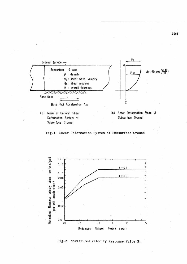
According to multi-reflection assumption, subsurface ground motion during earthquakes are attributed primarily to upward propagation of shear waves from underlying base rocks. In such cases the ground motion induced by a seismic excitation at the base rock is considered to be shear deformation of the subsurface.
The subsurface has varying dynamic properties in actual spaces, then assuming a simple case of a uniform soil profile as shown in Fig. 1, amplitude can be estimated as follows,
BULLETIN OF THE NEW ZEALAND NATIONAL SOCIETY FOR EARTHQUAKE ENGINEERING, VOL.7, NO.4. DECEMBER 1974.
201
Uh = -TT
where Uh
T 2TT
Sv Aoh (1)
Aoh Sv
amplitude of ground displacement (cm) , natural period of subsurface ground (sec.), amplitude of base rock maximum acceleration (gal), and normalized velocity response values as shown in Fig. 2.
The values of Sv are given by average response spectra for rock bases evaluated from observed strong motion accelerations.
Assuming a sinusoidal deformation of the ground as follows,
U(x) = where L
Uh sin (~̂ x -f JL
(2)
wave length (cm), phase angle (rad.), and variable of the space (cm),
the maximum principal distortion on the horizontal plane Ymax c a n b e obtained as followss
7 max ^ Uh Ju
(3)
a 2 = 1 +
where I = /"2L
for Eq. (5) & (6), (8)
apparent wave length in the case of 6 = TT/4 rad. (cm) ,
\ i = / K i / E A
X2 ^VHKTTEI (1/cm), (1/cm),
Ki : longitudinal stiffness property of elastic foundation per unit length of principal structure (kg/cm 2), and
K 2 : transverse stiffness property of elastic foundation per unit length of principal structure (kg/cm2).
Accordingly, the real forces are evaluated as follows ,
P
M
«i Uh , 4 T T 2 E I „ .
a 2 - ^ - z — Uh
Q = a 2
L< 8 T T 3 E I Uh
(9)
(10)
(11)
Applying the distortion to the tunnel where P structure, sectional forces of the structure M are apparently evaluated as follows, Q
Pap =
Map
2 IT sin 9 cos
4 T T 2 C O S 3
EA Uh
EI Uh
_ 8 TT 3 cos ** i Qap = p EI * Uh '
(4)
(5)
(6)
where Pap : apparent axial force (kg), Map : apparent bending moment (kg. cm), Qap : apparent shearing force (kg), E : Young's modulus of the tunnel
structure (kg/cm 2), A : sectional area of the principal
structure (cm 2), I : moment of inertia of the
principal structure (cm^), and 6 : angle between principal
distortion axis and the structural axis (rad.).
The maximum axial force is derived from Eq. (4) with an angle 6 of TT/4 rad. and the maximum bending moment and shearing force from Eq. (5) and Eq. (6) with an angle 0 of zero.
The tunnel has larger rigidities than the surrounding subsurface, accordingly the behaviour of the tunnel structure is not the same as that of the surrounding subsurface.
Assuming the structure as an embedded rod or beam supported on elastic foundations, reduced deformations of the structure to the surrounding subsurface can be found. The reduction factors which give real sectional forces applying to Eq. (4), (5) and (6) are expressed as follows,
a i = for Eq. (4), (7)
axial force, bending moment, and shearing force.
From Eq. (9), (10) and (11) maximum forces are obtained provided the wave lengths are estimated as follows,
Lp =
Lm
Lq
2TT
2TT
2TT X 2
(12)
(13)
(14)
where Lp : wave length which makes the axial force of Eq. (9) maximum (cm) ,
Lm : wave length which makes the bending moment of Eq. (10) maximum (cm), and
Lq : wave length which makes the shearing force of Eq. (11) maximum (cm)
Consequently the sectional forces of (9) , (10) and (11) become as follows,
P* = / K T EA Uh
VK2 EI Uh
Q* =
(15)
(16)
(17)
EARTHQUAKE RESPONSE ANALYSIS (5)
Assuming the subsoil as lumped mass system and the submerged tunnel as elastically supported rod or beam on the ground, the displacement and sectional
202
forces of the structure are calculated by the seismic exitation at the base rock.
In the response analysis of the ground, it is assumed that the natural frequency of the ground is not affected by the existence of a submerged tunnel. This analysis is based on the un-uniformity of the geometry, geology and stratum of the ground, therefore no sectional forces are developed in the tunnel embedded in the uniform subsoils.
root-mean-square principle. The sectional forces near the ends of the tunnel are corrected to satisfy the boundary condition that the tunnel is free from the ventilation tower.
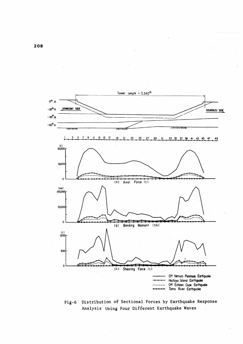
In the earthquake response analyses, four different earthquake waves and one average response spectrum as shown in Table 1. are employed. These four earthquake waves are selected in general for the following reasons.
4. NUMERICAL EXAMPLE The submerged tunnel is assumed to be
3,340 m long and rectangular section with 44.2 m width and 13 m height. These dimensions are determined with reference to the preliminary design of proposed Tokyo Bay Highway Crossing.
The elements of tunnel are treated to be connected rigidly and the tunnel is free from the ventilation tower.
The layer below 30 to 4 0 m from the surface is estimated as the base rock. The rigidities of subsoils are evaluated from the unit weights and the design shear wave velocities which have been taken as one-half of the small amplitude seismic wave velocities d> 7 ) . Damping ratio is determined to be 20% by considering the shear strain level during earthquake ( 7).
The subsoils consist of two or three layers with different shear wave velocities. For these cases the natural period of these subsoils have been estimated by assuming the subsoils as uniform soil layer with converted shear wave velocities, that is,
m — 4H _ r 4Hi Vsc £ Vsi (18)
where, H and V s c are the overall thickness (cm) and converted shear wave velocity of subsoil (cm/sec) respectively. and V s£ are thickness and design shear wave velocity of the i th layer respectively. The natural periods of the subsoils are about 1.0 to 2.5 seconds.
The stiffness properties between tunnel and subsoil Ki and K2 are estimated by considering the tunnel to be rigid rectangular plate on the semi-finite elastic body as follows, Ki = K 2 = G s (19)
where, G s is the average shear modulus of subsoil evaluated from unit weight and design shear wave velocity.
In the seismic deformation analysis, the base rock acceleration in Eq. (1) is taken to be 150 gals. U h in Eq. (9), (10) and (11) is taken to be the displacement at the center of gravity of tunnel and this is obtained by the shear deformation mode presented in Fig. 1.
In this case, combination of axial forces of the structure due to a couple of waves which propagate orthogonally through the x-y plane in Fig. 3 is treated by the
(1) The soil conditions at the recorded places are similar to those of base rock.
(2) The earthquake waves to be recorded near the construction site of the tunnel.
(3) The epicentral distances and magnitudes of earthquakes can be classified into the following three categories,
(i) large earthquakes with long epicentral distances Off Nemuro Peninsula Earthquake (M=7.4, D=305 km)
Hachijyo Island Earthquake (M=7.2, D=275 km)
(ii) medium earthquake with medium epicentral distances Off Echizen Cape Earthquake (M=6.9, D=153 km)
(iii) small earthquake with short epicentral distance Tama River Earthquake (M=4.5, D=8 km)
The maximum base rock accelerations have been taken as the recorded maximum accelerations, that is, without normalization of maximum accelerations to take account of the magnitude and epicentral distance. However the results with normalizing of the maximum base rock accelerations to be 150 gals are also obtained to compare the response level of the sectional forces.
The coefficients of response acceleration (per unit acceleration, damping ratio h=20%) for the four earthquake waves and average response spectrum are presented in Fig. 4.
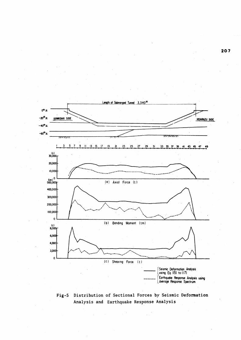
Numerical Results for the sectional forces developed in the submerged tunnel are shown in Fig. 5 and Fig. 6. Fig. 5 shows the comparison of distribution of sectional forces estimated by seismic deformation analysis using Eq. (15) to Eq. (17) and earthquake response analysis using average response spectrum. Fig. 6 shows the comparisons .of distributions of sectional forces estimated by earthquake response analysis using the four different earthquake waves.
From these numerical results the following points are observed, (1) the sectional forces evaluated by the
earthquake response analysis are smaller than those evaluated by the seismic deformation analysis,
(2) in the earthquake response analyses, the sectional forces on tunnels embedded in near uniform subsurface ground become very small. Next, in order to compare the response
levels, the sectional forces with
203
normalization of the base rock maximum accelerations to be 150 gals are presented in Table 3, In Table 3 , two cases of the axial forces evaluated by earthquake response analyses are larger than those estimated by seismic deformation analysis. However, the normalization of base rock accelerations to be 150 gals without taking account of magnitudes and epicentral distances may give rise to excessively large earthquakes. The appropriate treatments for these cases have the necessities for more detailed research. 5. NATURAL FREQUENCIES OF SUBSURFACE
GROUNDS DUETO MODEL TESTING Model vibration tests of submerged tunnel
and surrounding subsoils have been conducted. The model subsoil consists of five layers
with different shear moduli and the ratio of shear moduli between the stiffest layer and the softest layer is about 1:13.
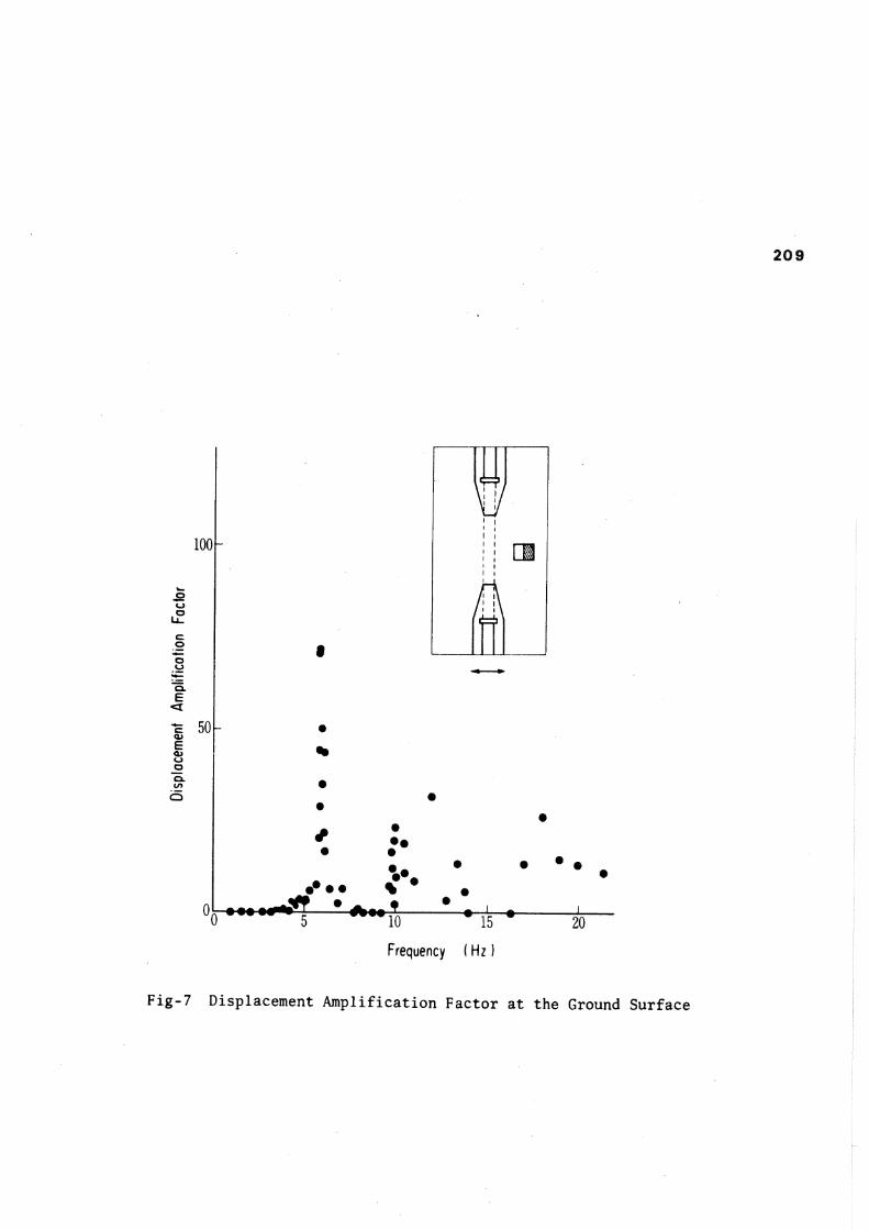
The model base rock has been excited by sinusoidal waves with varying frequencies from 0 to 20 Hz (these frequencies correspond to 0 to 4 Hz in the actual ground). The displacement amplification factors for each frequency are obtained by dividing the response displacements at model ground surface by the ones at the base rock. One of the displacement amplification factors is presented in Fig. 7. The most predominant frequency is about 5.9 Hz.
The natural frequency of this model subsoil estimated by Eq. (18) is about 6.8 Hz. Therefore the relative difference with the test result is about 13% even in this case,
The first natural frequency evaluated from plane strain finite element analysis for cross section of model subsoil is about 5. 5 Hz. The relative difference with the test result is about 8%.
From these results the accuracy in estimation of natural period mentioned previously is reliable.
(4) The model testing is a useful method for evaluating the dynamic behaviour of ground subsurface with geological and geodetic properties. 7. REFERENCES (1) Arsons Brickerhoff-Tuder-Bechtel:
Trans-Bay Tube-Technical Supplement to the Engineering Report, July 1969.
(2) Aoki, Y.: Seismic Design Spectra for Trench Type Tunnel, Proc. JSCE, No. 211, March, 1973, pp.77-87.
(3) Kuesel, T. R.: Earthquake Design Criterion for Subways, Proc. ASCE, Vol. 95, No. ST6, July, 1969, pp.1213-1231.
(4) Kuribayashi, E., et al: Effects of Seismic and Subsoil Conditions on Earthquake Response Spectra, 5th WCEE, Dec., 1972.
(5) Okamoto, S. and Tamura.: Behaviour of Subaqueous Tunnels during Earthquakes, Earthquake Engineering and Structural Dynamics, Vol. 1, 1973, pp.253-266.
(6) Okamoto, S.: Introduction to Earthquake Engineering, University of Tokyo Press, 1973, p.98.
(7) Seed, H. B. and Idriss, I. M.: Soil Moduli and Damping Factors for Dynamic Response Analysis, Report No. EERC 70-10, University of California, Berkeley.
6. CONCLUSIONS A seismic deformation analysis is
proposed and results of earthquake response analysis checked in an application to the longitudinal analysis of a submerged tunnel. From these results it is concluded that, (1) In the earthquake response analysis of lumped mass system^ the sectional forces in the tunnel induced by the large earthquakes with long epicentral distances are larger than those by small earthquake with short epicentral distance, because of the comparatively long natural period of the ground subsurface. (2) In the earthquake response analysis, no sectional force of the tunnel embedded in the uniform subsurface is principally developed, also the same trend is given in the numerical results. (3) In the seismic deformation analysis, the sectional forces of the tunnel embedded in the uniform subsurface can be obtained assuming the appropriate wave length.
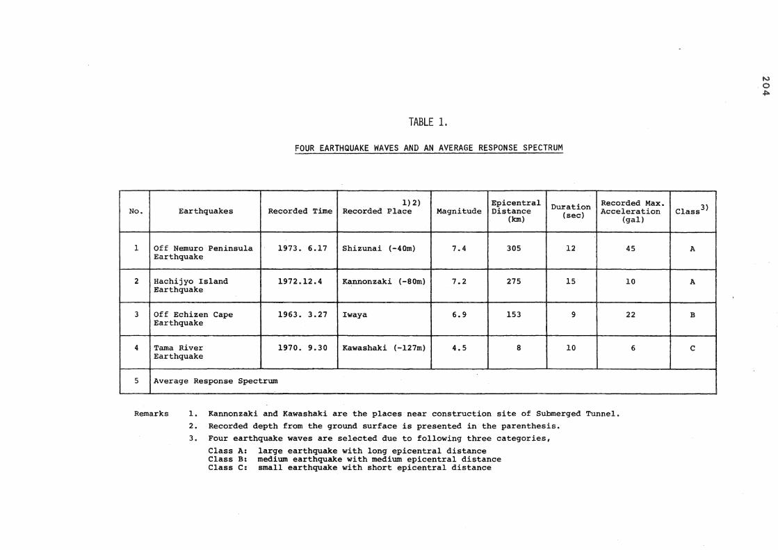
TABLE 1 .
FOUR EARTHQUAKE WAVES AND AN AVERAGE RESPONSE SPECTRUM
No. Earthquakes Recorded Time 1)2)
Recorded Place Magnitude Epicentral Distance
(km) Duration
(sec) Recorded Max. Acceleration
(gal) Class3*
1 Off Nemuro Peninsula Earthquake
1973. 6.17 Shizunai (-40m) 7.4 305 12 45 A
2 Hachijyo Island Earthquake
1972.12.4 Kannonzaki (-80m) 7.2 275 15 10 A
3 Off Echizen Cape Earthquake
1963. 3.27 Iwaya 6.9 153 9 22 B
4 Tama River Earthquake
1970. 9.30 Kawashaki (-127m) 4.5 8 10 6 C
5 Average Response Spectrum
Remarks 1. Kannonzaki and Kawashaki are the places near construction site of Submerged Tunnel. 2. Recorded depth from the ground surface is presented in the parenthesis. 3. Four earthquake waves are selected due to following three categories.
Class A: large earthquake with long epicentral distance Class B: medium earthquake with medium epicentral distance Class C: small earthquake with short epicentral distance
2 0 5
Ground Surface
Subsurface Ground
P
Vs 6s H
density shear wave velocity shear modulus overall thickness
Base Rock
Base Rock Acceleration Aoh
( a ) Model of Uniform Shear Deformation System of Subsurface Ground
7 Uzr-Uh cos ( f j f )
(b) Shear Deformation Mode of Subsurface Ground
Fig-1 Shear Deformation System of Subsurface Ground
r— s — i — i i i n r
h = 0.1
h = 0.2
o E 0 . 0 1 —L— 1 J L_| | | ) J L_
0.2 0.5 1 2
Undamped Natural Period ( sec )
J L
Fig-2 Normalized Velocity Response Value S v
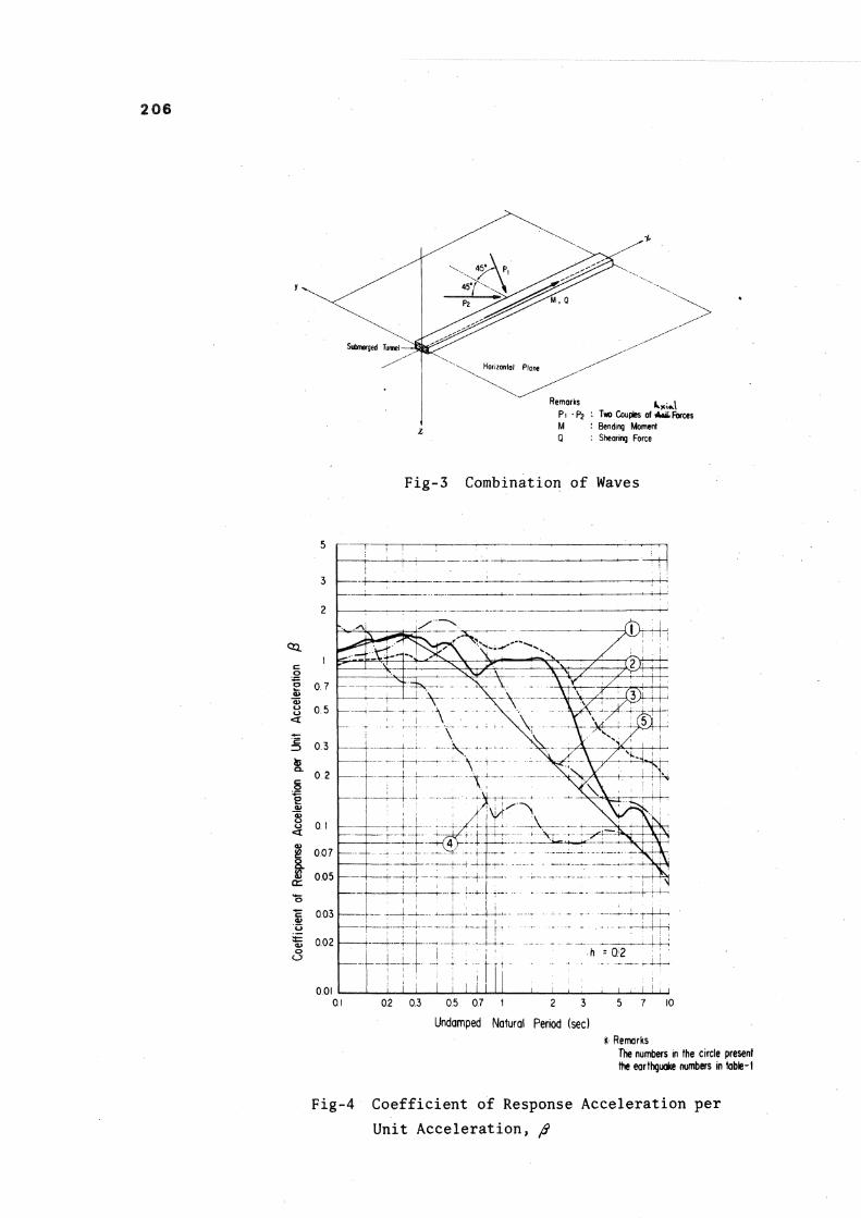
206
Q : Shearing Force
Fig-3 Combination of Waves
Fig-4 Coefficient of Response Acceleration per Unit Acceleration, ft
207
Length of Submerged Tunnel 3 . 3 4 0 m
(t) 30,000
20,000
10,000
d m ) 0
500,000-
400,000
300,000
200,000
100,000-
0
(t) 8,000
6,000-
4,000
2P00
0
(a ) Axiol Force ( t )
(b) Bending Moment ( tm)
v .
(c ) Shearing Force ( t )
[Seismic Deformation Analysis Using Eq. (15) to (17)
Earthquake Response Analysis using Average Response Spectrum
Fig-5 Distribution of Sectional Forces by Seismic Deformation Analysis and Earthquake Response Analysis
208
Tunnel Length = 3 , 3 4 0
( c ) Shearing Force ( t )
Off Nemuro Peninsula Earthguoke 9 0 ° c Hachtjyo Island Earthguake
Off Echizen Cape Earthguake "»"«MW v Tama River Earthguake
Fig-6 Distribution of Sectional Forces by Earthquake Response Analysis Using Four Different Earthquake Waves
2 0 9
Fig-7 Displacement Amplification Factor at the Ground Surface