Embed Size (px)
Citation preview
International Journal of Solids and Structures 49 (2012) 1637–1655
Contents lists available at SciVerse ScienceDirect
International Journal of Solids and Structures
journal homepage: www.elsevier .com/locate / i jsols t r
Dynamic curving cracks in functionally graded materials underthermo-mechanical loading
Sandeep Abotula a, Addis Kidane b, Vijaya B. Chalivendra c, Arun Shukla a,⇑a Dynamic Photo Mechanics Laboratory, Department of Mechanical, Industrial & Systems Engineering, University of Rhode Island, Kingston, RI 02881, United Statesb Department of Mechanical Engineering, University of South Carolina, Columbia, South Carolina 29208, United Statesc Department of Mechanical Engineering, University of Massachusetts Dartmouth, North Dartmouth, MA 02747, United States
a r t i c l e i n f o a b s t r a c t
Article history:Received 30 November 2010Received in revised form 27 January 2012Available online 23 March 2012
Keywords:Thermo-mechanical stress fieldsCurving cracksFunctionally graded materialsAsymptotic analysis
0020-7683/$ - see front matter � 2012 Elsevier Ltd. Ahttp://dx.doi.org/10.1016/j.ijsolstr.2012.03.010
⇑ Corresponding author. Tel.: +1 401 874 2283; faxE-mail addresses: [email protected] (S. A
(A. Kidane), [email protected] (V.B. Chaliv(A. Shukla).
Mixed-mode dynamic crack growth along an arbitrarily smoothly varying path in functionally gradedmaterials (FGMs) under thermo-mechanical loading is studied. The property gradation in FGMs is consid-ered by varying shear-modulus, mass density, thermal conductivity and coefficient of thermal expansionexponentially along the gradation direction. Asymptotic analysis in conjunction with displacementpotentials is used to develop the stress fields around propagating cracks in FGMs. Asymptotic tempera-ture fields are developed first for the exponential variation of thermal conductivity and later these tem-perature fields are used to derive thermo-mechanical stress fields for a curving crack in FGMs. Usingthese thermo-mechanical stress fields, various components of the stresses are developed and the effectof curvature parameters, temperature and gradation on these stresses are discussed. Finally, using theminimum strain energy density criterion, the effect of curvature parameters, crack-tip speeds, non-homogeneity values and temperature gradients on crack growth directions are determined anddiscussed.
� 2012 Elsevier Ltd. All rights reserved.
1. Introduction
Functionally graded materials (FGMs) are essentially non-homogeneous composites which have characteristics of spatiallyvarying microstructure and mechanical/thermal properties to meeta predetermined functional performance (e.g., Niino et al., 1987;Suresh and Mortensen, 1998). Although their performance inreal-life engineering applications is still under investigation, FGMshave shown promising results when they are subjected to thermo-mechanical loading (e.g., Suresh and Mortensen, 1998). There is anextensive amount of literature published on the fracture mechan-ics of FGMs under both quasi-static loading conditions (e.g., Delaleand Erdogan, 1983; Schovanec and Walton, 1988; Konda andErdogan, 1994; Gu and Asaro, 1997; Wu and Erdogan, 1997; Jinet al., 2002; Kim and Paulino, 2002; Parameswaran and Shukla,2002; Chalivendra et al., 2003; Kubair et al., 2005; Chalivendra,2008, 2009; Zhang and Kim, 2011) and dynamic loading conditions(e.g., Atkinson and List, 1978; Krishnaswamy et al., 1992;Parameswaran and Shukla, 1999; Rousseau and Tippur, 2001;Chalivendra et al., 2002; Shukla and Jain, 2004; Chalivendra and
ll rights reserved.
: +1 401 874 2355.botula), [email protected]), [email protected]
Shukla, 2005; Abanto-Bueno and Lambros, 2006; Kirugulige andTippur, 2008).
The research output on the thermo-mechanical response ofFGM’s is limited. Hasselman and Youngblood (1978) were amongthe first to study thermal stresses in nonhomogeneous structuresassociated with thermo-mechanical loading. By introducing a ther-mal conductivity gradient, they demonstrated significant reduc-tions in the magnitude of the tensile thermal stress in ceramiccylinders. In other studies, thermal residual stresses were relaxedin metal-ceramic layered materials by inserting a functionallygraded interface layer between the metal and ceramic (e.g.,Kawasaki and Wantanabe, 1987; Drake et al., 1993; Giannakopou-los et al., 1995). In their studies, Kuroda et al. (1993) and Takahashiet al. (1993) reported that when subjected to thermal shocks, FGMcoatings suffer significantly less damage than conventional ceramiccoatings.
In continuation of the above studies, several studies on thequasi-static fracture of FGMs under thermo-mechanical loadinghave been reported. Assuming exponential variation of materialproperties, Jin and Noda (1994) investigated the steady thermalstress intensity factors in functionally graded semi-infinite spacewith an edge crack subjected to thermal load. Later, Erdogan andWu (1996) also determined the steady thermal stress intensityfactor of a FGM layer with a surface crack perpendicular to theboundaries. By further assuming the exponential variation of ther-mal and mechanical properties of the materials, Jin and Batra
1638 S. Abotula et al. / International Journal of Solids and Structures 49 (2012) 1637–1655
(1996) investigated the stress intensity relaxation problem at thetip of an edge crack in a FGM subjected to a thermal shock. Byemploying a finite element method (FEM), Noda (1997) analyzedan edge crack problem in a zirconia/titanium FGM plate subjectedto cyclic thermal loads. Jin and Paulino (2001) studied transientthermal stresses in a FGM with an edge crack having a constantPoisson’s ratio and Young’s Modulus but varying thermal propertiesalong the thickness direction. Walters et al. (2004) developed gen-eral domain integral methods to obtain the stress intensity factorsfor the surface cracks in FGMs under mode-I thermo-mechanicalloading conditions.
The above studies provide closed form solutions for stressintensity factors under thermo-mechanical loading, however forextracting fracture parameters from experimental studies, theasymptotic expansion of thermo-mechanical stress fields aroundthe crack-tip are essential (e.g., Kirugulige and Tippur, 2008). Re-cently in this direction, Jain et al. (2006) developed quasi-staticstress and displacement fields for a crack in an infinite FGM med-ium under thermo-mechanical loading. However, there were nostudies until recently on the dynamic crack growth under ther-mo-mechanical loads. Lee et al. (2008) developed analyticalexpressions for the dynamic crack-tip stress and displacementfields under thermo-mechanical loading in FGMs. Kidane et al.(2010a) developed the stress fields and strain energy associatedwith a propagating crack in a homogeneous material under ther-mo-mechanical loading using an asymptotic approach. Very re-cently, Kidane et al. (2010b) also developed stress field equationsfor dynamic crack propagation in FGMs under thermo-mechanicalloading. Even though the above mentioned studies of dynamicthermo-mechanical asymptotic field equations serve the purposeof obtaining fracture parameters from experimental data, thesestudies have not incorporated the crack path curvature associatedwith a propagating crack in these materials. It has been reported inthe experimental and numerical studies that the propagatingcracks follow curved paths under various loading conditions dueto the spatial variation of properties in graded materials (e.g.,Lambros et al., 2000; Noda et al., 2003; Tohgo et al., 2005; Tilbrooket al., 2005). In order to extract the fracture parameters accuratelyfrom the experimental data associated with curved cracks, it isessential to consider curvature terms in the field equations. Liuand Rosakis (1994) developed the higher-order asymptotic expan-sion of a non-uniformly propagating dynamic crack along an arbi-trary curved path for homogeneous materials and they emphasized
X (t)
2ζ
s (t)
y
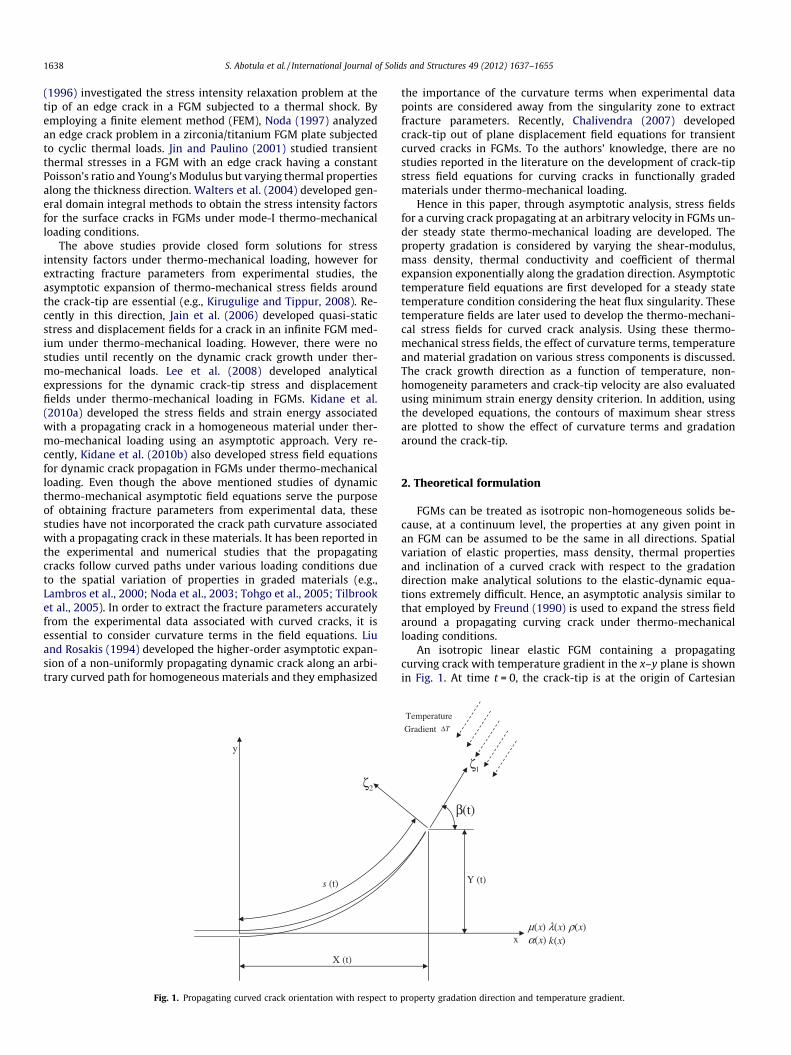
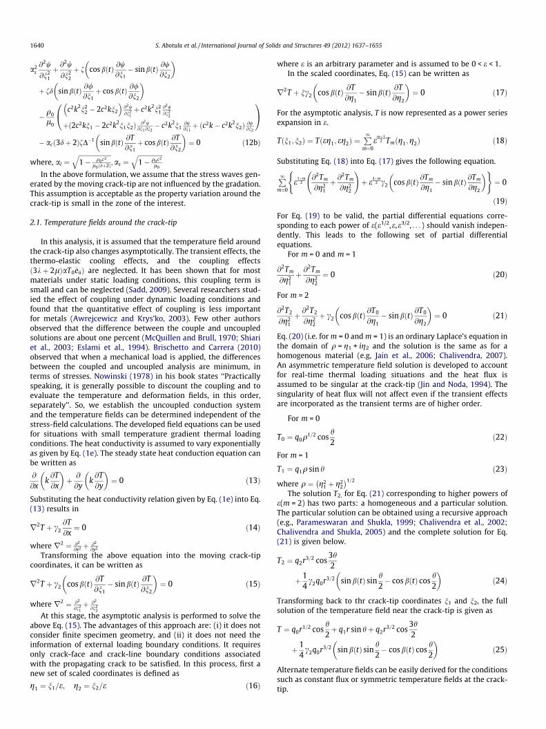
Fig. 1. Propagating curved crack orientation with respect to
the importance of the curvature terms when experimental datapoints are considered away from the singularity zone to extractfracture parameters. Recently, Chalivendra (2007) developedcrack-tip out of plane displacement field equations for transientcurved cracks in FGMs. To the authors’ knowledge, there are nostudies reported in the literature on the development of crack-tipstress field equations for curving cracks in functionally gradedmaterials under thermo-mechanical loading.
Hence in this paper, through asymptotic analysis, stress fieldsfor a curving crack propagating at an arbitrary velocity in FGMs un-der steady state thermo-mechanical loading are developed. Theproperty gradation is considered by varying the shear-modulus,mass density, thermal conductivity and coefficient of thermalexpansion exponentially along the gradation direction. Asymptotictemperature field equations are first developed for a steady statetemperature condition considering the heat flux singularity. Thesetemperature fields are later used to develop the thermo-mechani-cal stress fields for curved crack analysis. Using these thermo-mechanical stress fields, the effect of curvature terms, temperatureand material gradation on various stress components is discussed.The crack growth direction as a function of temperature, non-homogeneity parameters and crack-tip velocity are also evaluatedusing minimum strain energy density criterion. In addition, usingthe developed equations, the contours of maximum shear stressare plotted to show the effect of curvature terms and gradationaround the crack-tip.
2. Theoretical formulation
FGMs can be treated as isotropic non-homogeneous solids be-cause, at a continuum level, the properties at any given point inan FGM can be assumed to be the same in all directions. Spatialvariation of elastic properties, mass density, thermal propertiesand inclination of a curved crack with respect to the gradationdirection make analytical solutions to the elastic-dynamic equa-tions extremely difficult. Hence, an asymptotic analysis similar tothat employed by Freund (1990) is used to expand the stress fieldaround a propagating curving crack under thermo-mechanicalloading conditions.
An isotropic linear elastic FGM containing a propagatingcurving crack with temperature gradient in the x–y plane is shownin Fig. 1. At time t = 0, the crack-tip is at the origin of Cartesian
Y (t)
1ζ
β(t)
Temperature
Gradient TΔ
)(xμ )(xλ )(xρ)(xα )(xkx
property gradation direction and temperature gradient.
S. Abotula et al. / International Journal of Solids and Structures 49 (2012) 1637–1655 1639
coordinate system x-y. For any time t > 0, the position of the prop-agating crack-tip is given by (X(t) and Y(t)) as shown in Fig. 1. Shearmodulus (l), Lamé’s constant (k), density (q), thermal expansion(a) and heat conductivity (k) of the FGM are assumed to vary inan exponential manner as given by Eqs. (1a)–(1e), whereas, Pois-son’s ratio (m) is assumed to be a constant. Experimental studies(e.g., Shukla and Jain, 2004; Yao et al., 2007) reported in the liter-ature support the exponential variation of modulus of elasticityand mass density.
l ¼ l0 expðfxÞ ð1aÞk ¼ k0 expðfxÞ ð1bÞq ¼ q0 expðfxÞ ð1cÞa ¼ a0 expðc1xÞ ð1dÞk ¼ k0 expðc2xÞ ð1eÞ
The equations of motion for a plane problem are given by Eq. (2)
@rxx
@xþ @sxy
@y¼ q
@2u@t2 ð2aÞ
@sxy
@xþ @ryy
@y¼ q
@2v@t2 ð2bÞ
The relationship between stresses and strains for a plane strainthermo-mechanical problem can be written as
rxx ¼ expðfxÞ½k0 þ 2l0Þexx þ k0eyy � ð3k0 þ 2l0Þa0 expðc1xÞT� ð3aÞ
ryy ¼ expðfxÞ½k0exx þ ðk0 þ 2l0Þeyy � ð3k0 þ 2l0Þa0 expðc1xÞT� ð3bÞ
sxy ¼ expðfxÞl0cxy ð3cÞ
where x and y are reference coordinates, rij and eij (where i = x,y andj = x,y) are in-plane stress and strain components, and subscript ‘‘o’’means at x = 0 as shown in Fig. 1. T represents the change in temper-ature in the infinite medium, f, c1 and c2 are non-homogeneity con-stants that have the dimension (length)�1. Each physical variablecan have a different non-homogeneity parameter. However formathematical simplicity only three non-homogeneity parameters,one for mechanical properties and two for thermal properties, areconsidered. For a plane strain deformation, the displacements uand v are derived from dilatational and shear wave potentials Uand W. So, displacements can be expressed in terms of potentialsas given below
u ¼ @/@xþ @w@y
; v ¼ @/@y� @w@x
ð4Þ
Substituting for the stresses and density from (3) and (1) respec-tively into Eq. (2) and after simplification, the equations of motionare written as
ðk0 þ 2l0Þr2r2/þ f ðk0 þ 2l0Þ@
@xr2/þ l0
@
@yr2w
� �
� acð3k0 þ 2l0Þ ðc1 þ fÞc1T þ ð2c1 þ fÞ @T@x
� �þr2T
� �
¼ q0@2
@t2r2/ ð5aÞ
l0r2r2wþ f l0@
@xr2wþ k0
@
@yr2/
� �� acð3k0 þ 2l0Þf
@T@y
¼ q0@2
@t2r2w ð5bÞ
where ac is the coefficient of thermal expansion in the vicinity ofthe instantaneous crack-tip and is assumed to be constant.
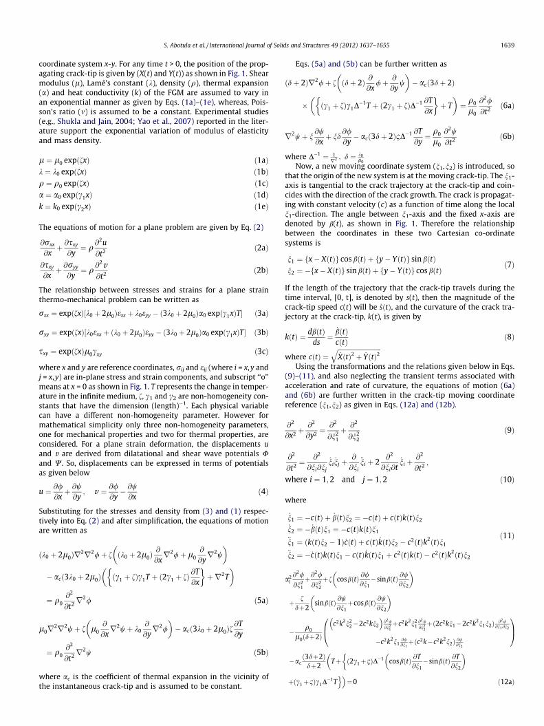
Eqs. (5a) and (5b) can be further written as
ðdþ 2Þr2/þ f ðdþ 2Þ @@x
/þ @
@yw
� �� acð3dþ 2Þ
� ðc1 þ fÞc1D�1T þ ð2c1 þ fÞD�1 @T
@x
� �þ T
� �¼ q0
l0
@2/
@t2 ð6aÞ
r2wþ n@w@xþ nd
@/@y� acð3dþ 2Þ1D�1 @T
@y¼ q0
l0
@2w
@t2 ð6bÞ
where D�1 ¼ 1r2 ; d ¼ k0
l0
Now, a new moving coordinate system (n1,n2) is introduced, sothat the origin of the new system is at the moving crack-tip. The n1-axis is tangential to the crack trajectory at the crack-tip and coin-cides with the direction of the crack growth. The crack is propagat-ing with constant velocity (c) as a function of time along the localn1-direction. The angle between n1-axis and the fixed x-axis aredenoted by b(t), as shown in Fig. 1. Therefore the relationshipbetween the coordinates in these two Cartesian co-ordinatesystems is
n1 ¼ fx� XðtÞg cos bðtÞ þ fy� YðtÞg sin bðtÞn2 ¼ �fx� XðtÞg sin bðtÞ þ fy� YðtÞg cos bðtÞ
ð7Þ
If the length of the trajectory that the crack-tip travels during thetime interval, [0, t], is denoted by s(t), then the magnitude of thecrack-tip speed c(t) will be _sðtÞ, and the curvature of the crack tra-jectory at the crack-tip, k(t), is given by
kðtÞ ¼ dbðtÞds¼
_bðtÞcðtÞ ð8Þ
where cðtÞ ¼ffiffiffiffiffiffiffiffiffiffiffiffiffiffiffiffiffiffiffiffiffiffiffiffiffiffiffiffi_XðtÞ2 þ _YðtÞ2
qUsing the transformations and the relations given below in Eqs.
(9)–(11), and also neglecting the transient terms associated withacceleration and rate of curvature, the equations of motion (6a)and (6b) are further written in the crack-tip moving coordinatereference (n1,n2) as given in Eqs. (12a) and (12b).
@2
@x2 þ@2
@y2 ¼@2
@n21
þ @2
@n22
ð9Þ
@2
@t2 ¼@2
@ni@nj
_ni_nj þ
@
@ni
€ni þ 2@2
@ni@t_ni þ
@2
@t2 ;
where i ¼ 1;2 and j ¼ 1;2 ð10Þ
where
_n1 ¼ �cðtÞ þ _bðtÞn2 ¼ �cðtÞ þ cðtÞkðtÞn2
_n2 ¼ � _bðtÞn1 ¼ �cðtÞkðtÞn1
€n1 ¼ ðkðtÞn2 � 1Þ _cðtÞ þ cðtÞ _kðtÞn2 � c2ðtÞk2ðtÞn1
€n2 ¼ � _cðtÞkðtÞn1 � cðtÞ _kðtÞn1 þ c2ðtÞkðtÞ � c2ðtÞk2ðtÞn2
ð11Þ
a2l@2/
@n21
þ@2/
@n22
þf cosbðtÞ @/@n1�sinbðtÞ @/
@n2
� �
þ fdþ2
sinbðtÞ @w@n1þcosbðtÞ @w
@n2
� �
� q0
l0ðdþ2Þ
c2k2n22�2c2kn2
� �@2/@n2
1þc2k2n2
1@2/@n2
2þð2c2kn1�2c2k2n1n2Þ @2/
@n1@n2
�c2k2n1@/@n1þðc2k�c2k2n2Þ @/@n2
0B@
1CA
�acð3dþ2Þ
dþ2Tþ ð2c1þ1ÞD�1 cosbðtÞ @T
@n1�sinbðtÞ @T
@n2
� ���
þðc1þ1Þc1D�1To�¼0 ð12aÞ
1640 S. Abotula et al. / International Journal of Solids and Structures 49 (2012) 1637–1655
a2s@2w
@n21
þ @2w
@n22
þ f cos bðtÞ @w@n1� sin bðtÞ @w
@n2
� �
þ fd sin bðtÞ @/@n1þ cos bðtÞ @/
@n2
� �
� q0
l0
c2k2n22 � 2c2kn2
� �@2w@n2
1þ c2k2n2
1@2w@n2
2
þð2c2kn1 � 2c2k2n1n2Þ @2w@n1@n2
� c2k2n1@w@n1þ ðc2k� c2k2n2Þ @w@n2
0@
1A
� acð3dþ 2ÞfD�1 sin bðtÞ @T@n1þ cos bðtÞ @T
@n2
� �¼ 0 ð12bÞ
where, al ¼ffiffiffiffiffiffiffiffiffiffiffiffiffiffiffiffiffiffiffiffiffi1� q0c2
l0ðdþ2Þ
q;as ¼
ffiffiffiffiffiffiffiffiffiffiffiffiffiffiffiffi1� q0c2
l0
qIn the above formulation, we assume that the stress waves gen-
erated by the moving crack-tip are not influenced by the gradation.This assumption is acceptable as the property variation around thecrack-tip is small in the zone of the interest.
2.1. Temperature fields around the crack-tip
In this analysis, it is assumed that the temperature field aroundthe crack-tip also changes asymptotically. The transient effects, thethermo-elastic cooling effects, and the coupling effectsð3kþ 2lÞaT0 _eiiÞ are neglected. It has been shown that for mostmaterials under static loading conditions, this coupling term issmall and can be neglected (Sadd, 2009). Several researchers stud-ied the effect of coupling under dynamic loading conditions andfound that the quantitative effect of coupling is less importantfor metals (Awrejcewicz and Krys’ko, 2003). Few other authorsobserved that the difference between the couple and uncoupledsolutions are about one percent (McQuillen and Brull, 1970; Shiariet al., 2003; Eslami et al., 1994). Brischetto and Carrera (2010)observed that when a mechanical load is applied, the differencesbetween the coupled and uncoupled analysis are minimum, interms of stresses. Nowinski (1978) in his book states ‘‘Practicallyspeaking, it is generally possible to discount the coupling and toevaluate the temperature and deformation fields, in this order,separately’’. So, we establish the uncoupled conduction systemand the temperature fields can be determined independent of thestress-field calculations. The developed field equations can be usedfor situations with small temperature gradient thermal loadingconditions. The heat conductivity is assumed to vary exponentiallyas given by Eq. (1e). The steady state heat conduction equation canbe written as
@
@xk@T@x
� �þ @
@yk@T@y
� �¼ 0 ð13Þ
Substituting the heat conductivity relation given by Eq. (1e) into Eq.(13) results in
r2T þ c2@T@x¼ 0 ð14Þ
where r2 ¼ @2
@x2 þ @2
@y2
Transforming the above equation into the moving crack-tipcoordinates, it can be written as
r2T þ c2 cos bðtÞ @T@n1� sin bðtÞ @T
@n2
� �¼ 0 ð15Þ
where r2 ¼ @2
@n21þ @2
@n22
At this stage, the asymptotic analysis is performed to solve theabove Eq. (15). The advantages of this approach are: (i) it does notconsider finite specimen geometry, and (ii) it does not need theinformation of external loading boundary conditions. It requiresonly crack-face and crack-line boundary conditions associatedwith the propagating crack to be satisfied. In this process, first anew set of scaled coordinates is defined as
g1 ¼ n1=e; g2 ¼ n2=e ð16Þ
where e is an arbitrary parameter and is assumed to be 0 < e < 1.In the scaled coordinates, Eq. (15) can be written as
r2T þ nc2 cos bðtÞ @T@g1� sin bðtÞ @T
@g2
� �¼ 0 ð17Þ
For the asymptotic analysis, T is now represented as a power seriesexpansion in e.
Tðn1; n2Þ ¼ Tðeg1; eg2Þ ¼P1
m¼0emþ1
2 Tmðg1;g2Þ ð18Þ
Substituting Eq. (18) into Eq. (17) gives the following equation.
P1m¼0
e1þm2
@2Tm
@g21
þ @2Tm
@g22
!þ e3þm
2 c2 cos bðtÞ @Tm
@g1� sin bðtÞ @Tm
@g2
� �( )¼ 0
ð19Þ
For Eq. (19) to be valid, the partial differential equations corre-sponding to each power of e(e1/2,e,e3/2, . . . ) should vanish indepen-dently. This leads to the following set of partial differentialequations.
For m = 0 and m = 1
@2Tm
@g21
þ @2Tm
@g22
¼ 0 ð20Þ
For m = 2
@2T2
@g21
þ @2T2
@g22
þ c2 cos bðtÞ @T0
@g1� sin bðtÞ @T0
@g2
� �¼ 0 ð21Þ
Eq. (20) (i.e. for m = 0 and m = 1) is an ordinary Laplace’s equation inthe domain of q = g1 + ig2 and the solution is the same as for ahomogenous material (e.g, Jain et al., 2006; Chalivendra, 2007).An asymmetric temperature field solution is developed to accountfor real-time thermal loading situations and the heat flux isassumed to be singular at the crack-tip (Jin and Noda, 1994). Thesingularity of heat flux will not affect even if the transient effectsare incorporated as the transient terms are of higher order.
For m = 0
T0 ¼ q0q1=2 cosh2
ð22Þ
For m = 1
T1 ¼ q1q sin h ð23Þ
where q ¼ g21 þ g2
2
1=2
The solution T2, for Eq. (21) corresponding to higher powers ofe(m = 2) has two parts: a homogeneous and a particular solution.The particular solution can be obtained using a recursive approach(e.g., Parameswaran and Shukla, 1999; Chalivendra et al., 2002;Chalivendra and Shukla, 2005) and the complete solution for Eq.(21) is given below.
T2 ¼ q2r3=2 cos3h2
þ 14c2q0r3=2 sin bðtÞ sin
h2� cos bðtÞ cos
h2
� �ð24Þ
Transforming back to thr crack-tip coordinates n1 and n2, the fullsolution of the temperature field near the crack-tip is given as
T ¼ q0r1=2 cosh2þ q1r sin hþ q2r3=2 cos
3h2
þ 14c2q0r3=2 sin bðtÞ sin
h2� cos bðtÞ cos
h2
� �ð25Þ
Alternate temperature fields can be easily derived for the conditionssuch as constant flux or symmetric temperature fields at the crack-tip.
S. Abotula et al. / International Journal of Solids and Structures 49 (2012) 1637–1655 1641
2.2. Asymptotic expansion of crack-tip stress fields
Similar to the derivation of the temperature field, the asymp-totic approach is again used in deriving the solutions for the dis-placement potentials for the equations of motion (12a) and(12b). The scaled coordinates, as discussed in Eq. (16), are now ap-plied to equations (12a) and (12b) as given belowAt this stage, it is assumed that U, w and T can be represented as apower series expansion in e.
a2l@2/
@g21
þ @2/
@g22
þ ef cos bðtÞ @/@g1� sin bðtÞ @/
@g2
� �þ ef
dþ 2sin bðtÞ @w
@g1þ cos bðtÞ @w
@g2
� �
� q0
l0ðdþ 2Þc2k2e2g2
2 � 2c2keg2
� �@2/@g2
1þ c2k2e2g2
1@2/@g2
2
þð2c2keg1 � 2c2k2e2g1g2Þ @2/@g1@g2
� c2k2e2g1@/@g1þ ðc2ke� c2k2e2g2Þ @/@g2
0@
1A
� acð3dþ 2Þ
dþ 2e2T þ e3ð2c1 þ 1ÞD�1 cos bðtÞ @T
@g1� sin bðtÞ @T
@g2
� �þ e4ðc1 þ 1Þc1D
�1T� �� �
¼ 0 ð26aÞ
a2s@2w
@g21
þ @2w
@g22
þ ef cos bðtÞ @w@g1� sin bðtÞ @w
@g2
� �þ efd sin bðtÞ @/
@g1þ cos bðtÞ @/
@g2
� �
� q0
l0c2k2e2g2
2 � 2c2keg2
� �@2w@g2
1þ c2k2e2g2
1@2w@g2
2þ ð2c2keg1 � 2c2k2e2g1g2Þ @2w
@g1@g2� c2k2e2g1
@w@g1þ ðc2ke� c2k2e2g2Þ @w@g2
� �
� acð3dþ 2Þe3fD�1 sin bðtÞ @T@g1þ cos bðtÞ @T
@g2
� �¼ 0 ð26bÞ
/ðn1; n2Þ ¼ /ðeg1; eg2Þ ¼P1
m¼0emþ3
2 /mðg1;g2Þ
wðn1; n2Þ ¼ wðeg1; eg2Þ ¼P1
m¼0emþ3
2 wmðg1;g2Þ
Tðn1; n2Þ ¼ Tðeg1; eg2Þ ¼P1
m¼0emþ1
2 qmðg1;g2Þ
ð27Þ
As discussed above, the temperature field is obtained by ensuringthat the heat flux or the derivative of the temperature field nearthe crack-tip is singular. This means that the potentials for temper-ature are one power less than the displacement potentials. Substi-tuting Eq. (27) into Eqs. (26a) and (26b) gives the followingequations.
P1m¼0
emþ32 a2
l@2/m@g2
1þ @2/m
@g22
� �þemþ5
2
f cosbðtÞ @/m@g1� sinbðtÞ @/m
@g2
� �þ
fdþ2 sinbðtÞ@wm
@g1þ cosbðtÞ@wm
@g2
� �264
375�
emþ52
q0l0ðdþ2Þ �2c2kg2
@2/m@g2
1þ2c2kg1
@2/m@g1@g2
þc2k @/m@g2
� �þac
ð3dþ2Þdþ2 Tm
h i�
emþ72
q0l0ðdþ2Þ
c2k2g22@2/m@g2
1þc2k2g2
1@2/m@g2
2�2c2k2g1g2
@2/m@g1@g2
�
c2k2g1@/m@g1� c2k2 @/m
@g2þ
acð3dþ2Þ
dþ2
� �ð2c1þ1ÞD�1 cosbðtÞ @Tm
@g1� sinbðtÞ@Tm
@g2
� �
0BBBB@
1CCCCA
266664
377775
�emþ92 ac
ð3dþ2Þdþ2 ðc1þ1Þc1D
�1Tm
h i
8>>>>>>>>>>>>>>>>>>><>>>>>>>>>>>>>>>>>>>:
9>>>>>>>>>>>>>>>>>>>=>>>>>>>>>>>>>>>>>>>;
¼0
ð28aÞ
P1m¼0
emþ32 a2
s@2wm@g2
1þ@
2wm@g2
2
� �þemþ5
2
f cosbðtÞ@wm@g1�sinbðtÞ@wm
@g2
� �þ
fd sinbðtÞ@/m@g1þcosbðtÞ@/m
@g2
� ��q0
l0�2c2kg2
@2wm@g2
1þ2c2kg1
@2wm@g1@g2
þc2k@wm@g2
� �
266664
377775
�emþ72
q0l0
c2k2g22@2wm@g2
1þc2k2g2
1@2wm@g2
2�2c2k2g1g2
@2wm@g1@g2
�c2k2g1@w@g1�
�c2k2 @w@g2
0@
1A
�acð3dþ2ÞfD�1 sinbðtÞ@Tm@g1þcosbðtÞ@Tm
@g2
� �
266664
377775
8>>>>>>>>>>>>>>><>>>>>>>>>>>>>>>:
9>>>>>>>>>>>>>>>=>>>>>>>>>>>>>>>;
¼0
ð28bÞ
For Eqs. (28a) and (28b) to be valid, the partial differential equa-tions corresponding to each power of e(e3/2, e2, e5/2, . . .) should van-ish independently. This leads to the following set of partialdifferential equations.
For m = 0 and m = 1,
a2l@2/m
@g21
þ @2/m
@g22
¼ 0 ð29aÞ
a2s@2wm
@g21
þ @2wm
@g22
¼ 0 ð29bÞ
For m = 2
a2l@2/2
@g21
þ@2/2
@g22
¼�f cosbðtÞ@/0
@g1�sinbðtÞ@/0
@g2
� �
� fdþ2
sinbðtÞ@w0
@g1þcosbðtÞ@w0
@g2
� �
þ q0
l0ðdþ2Þ �2c2kg2@2/0
@g21
þ2c2kg1@2/0
@g1@g2þc2k
@/0
@g2
!
þacð3dþ2Þ
dþ2T0
ð30aÞ
a2s@2w2
@g21
þ @2w2
@g22
¼ �f cos bðtÞ @w0
@g1� sin bðtÞ @w0
@g2
� �
� fd sin bðtÞ @/0
@g1þ cos bðtÞ @/0
@g2
� �
þ q0
l0�2c2kg2
@2w0
@g21
þ 2c2kg1@2w0
@g1@g2þ c2k
@w0
@g2
!
ð30bÞEqs. (29a) and (29b) are similar to those for a homogeneous mate-rial where the partial differential Eqs. (30a) and (30b), associatedwith the higher powers of e are coupled to the differentials of thelower order functions through the non-homogeneity parameters fand temperature term. Eqs. (29a) and (29b) (i.e. for m = 0 andm = 1) can be easily reduced to Laplace’s equation in the respectivecomplex domains 1l ¼ g1 þ ialg2; 1s ¼ g1 þ iasg2i ¼
ffiffiffiffiffiffiffi�1p
and thesolutions are the same as those for homogenous material (e.g., Fre-und, 1990; Gu and Asaro, 1997; Irwin, 1980; Shukla and Jain, 2004),and can be written as
/mðql; hl; tÞ ¼ Amqðmþ3Þ=2l cos 1
2 ðmþ 3Þhl þ Cmqðmþ3Þ=2l sin 1
2 ðmþ 3Þhl
wmðqs; hs; tÞ ¼ Bmqðmþ3Þ=2s sin 1
2 ðmþ 3Þhs þ Dmqðmþ3Þ=2s cos 1
2 ðmþ 3Þhs
ð31Þ
1642 S. Abotula et al. / International Journal of Solids and Structures 49 (2012) 1637–1655
where
ql ¼ g21 þ a2
l g22
� �1=2; tan hl ¼
alg2
g1; qs ¼ g2
1 þ a2s g
22
� �1=2; tan hs
¼ asg2
g1and Am; Cm Bm and Dm are real constants:
Using the definition of the dynamic stress intensity factor KID
and KIID for the opening mode and shear mode (Chalivendra,2007), the relation between Ao and KID, Co and KIID are obtained.
A0 ¼4 1þ a2
s
3 4alas � 1þ a2
s
2� � KID
lc
ffiffiffiffiffiffiffi2pp ; ð32Þ
C0 ¼8as
3 4alas � 1þ a2s
2� � KIID
lc
ffiffiffiffiffiffiffi2pp ; ð33Þ
where lc is thr crack-tip shear modulus, KID and KIID are the mode-Iand mode-II dynamic stress intensity factors, respectively.
Now, considering the crack face boundary conditions, r22 = 0and r12 = 0 we can also obtain the following relationship betweenAo, Bo, Co and Do
Bo ¼�2al
1þ a2s
Ao ð34Þ
Do ¼1þ a2
s
2asCo ð35Þ
In order to extract both mode-I and mode-II stress intensity factorsaccurately from the experimental data when the crack-tip stressfield is non-homogenous around the crack-tip due to imposed ther-mal fields and material non-homogeneity, higher-order stress-fieldequations are essential in addition to the leading terms and T-stress(non-singular stress). The solution for the Eqs. (30a) and (30b), cor-responding to higher powers of e(m = 2), consists of two parts: asolution for the homogeneous equation and a particular solutiondue to non-homogeneity and temperature and these can be obtainedrecursively (e.g., Parameswaran and Shukla, 1999; Chalivendra et al.,2002; Chalivendra and Shukla, 2005). The solutions /2 and w2 ob-tained are given below. The solutions for /0, w0, /1 and w1 automat-ically satisfy the compatibility equations because these solutions arethe same as those for homogeneous materials. Since the non-homo-geneous specific parts of /2 and w2 are obtained from /0 and w0,they also automatically satisfy the compatibility equations
/2 ¼ q5=2l A2 cos
5hl
2þ C2 sin
5hl
2
� �
� 14
f cos bðtÞa2
l
q5=2l A0 cos
hl
2þ C0 sin
hl
2
� �
þ 14
f sin bðtÞal
q5=2l �A0 sin
hl
2þ C0 cos
hl
2
� �
� 25
fdþ 2
sin bðtÞa2
l � a2s
q5=2s B0 sin
5hs
2þ D0 cos
5hs
2
� �
� 25
fdþ 2
as cos bðtÞa2
l � a2s
q5=2s B0 cos
5hs
2� D0 sin
5hs
2
� �
þ 14
q0
l0
1dþ 2
c2kal
q5=2l �A0 sin
hl
2þ C0 cos
hl
2
� �
� 116
q0
l0
1dþ 2
c2ka3
l
q5=2l A0 3 sin
3hl
2þ 2 sin
hl
2
��
�C0 2 coshl
2� 3 cos
3hl
2
��
þ 116
q0
l0
1dþ 2
c2kal
q5=2l A0 3 sin
3hl
2� 2 sin
hl
2
��
þC0 2 coshl
2þ 3 cos
3hl
2
��
þ 415
3dþ 2dþ 2
ac
a2l � 1
q0q5=2 cos52
h
� �ð36aÞ
w2 ¼ q5=2s B2 sin
5hs
2þ D2 cos
5hs
2
� �
� 14
f cos bðtÞa2
sq5=2
s B0 sinhs
2þ D0 cos
hs
2
� �
þ 14
f sin bðtÞas
q5=2s B0 cos
hs
2� D0 sin
hs
2
� �
þ 25
fd sin bðtÞa2
l � a2s
q5=2l A0 cos
5hl
2þ C0 sin
5hl
2
� �
þ 25
fdal cos bðtÞa2
l � a2s
q5=2l �A0 sin
5hl
2þ C0 cos
5hl
2
� �
þ 14
q0
l0
c2kas
q5=2s B0 cos
hs
2� D0 sin
hs
2
� �
� 116
q0
l0
c2ka3
sq5=2
s B0 3 cos3hs
2� 2 cos
hs
2
��
þD0 3 sin3hs
2þ 2 sin
hs
2
��
þ 116
q0
l0
c2kas
q5=2s B0 2 cos
hs
2þ 3 cos
3hs
2
��
þD0 3 sin3hs
2� 2 sin
hs
2
��ð36bÞ
By assembling together the above result for the first few terms andby transforming it back into the n1 � n2 plane, the combinedsolution can be written for / and w as Eqs. (37a) and (37b),
/¼ r3=2l A0 cos
32
hlþC0 sin32hl
� �þr2
l A1 cos2hlþC1 sin2hlð Þ
þr5=2l A2 cos
5hl
2þC2 sin
5hl
2
� ��1
4fcosbðtÞ
a2l
r5=2l A0 cos
hl
2þC0 sin
hl
2
� �
þ14
fsinbðtÞal
r5=2l �A0 sin
hl
2þC0 cos
hl
2
� �
�25
fdþ2
sinbðtÞa2
l �a2s
r5=2s B0 sin
5hs
2þD0 cos
5hs
2
� �
�25
fdþ2
as cosbðtÞa2
l �a2s
r5=2s B0 cos
5hs
2�D0 sin
5hs
2
� �
þ14q0
l0
1dþ2
c2kal
r5=2l �A0 sin
hl
2þC0 cos
hl
2
� �
� 116
q0
l0
1dþ2
c2ka3
l
r5=2l A0 3sin
3hl
2þ2sin
hl
2
��C0 2cos
hl
2�3cos
3hl
2
�� �
þ 116
q0
l0
1dþ2
c2kal
r5=2l A0 3sin
3hl
2�2sin
hl
2
�þC0 2cos
hl
2þ3cos
3hl
2
�� �
þ 415
3dþ2dþ2
ac
a2l �1
q0r5=2 cos52h
� �ð37aÞ
w ¼ r3=2s B0 sin
32
hs þ D0 cos32
hs
� �þ r2
s B1 sin 2hs þ D1 cos 2hsð Þ
þ r5=2s B2 sin
5hs
2þ D2 cos
5hs
2
� �
� 14
f cos bðtÞa2
sr5=2
s B0 sinhs
2þ D0 cos
hs
2
� �
þ 14
f sin bðtÞas
r5=2s B0 cos
hs
2� D0 sin
hs
2
� �
þ 25
fd sin bðtÞa2
l � a2s
r5=2l A0 cos
5hl
2þ C0 sin
5hl
2
� �
þ 25
fdal cos bðtÞa2
l � a2s
r5=2l �A0 sin
5hl
2þ C0 cos
5hl
2
� �
þ 14
q0
l0
c2kas
r5=2s B0 cos
hs
2� D0 sin
hs
2
� �
� 116
q0
l0
c2ka3
sr5=2
s B0 3 cos3hs
2� 2 cos
hs
2
�þ D0 3 sin
3hs
2þ 2 sin
hs
2
�� �
þ 116
q0
l0
c2kas
r5=2s B0 2 cos
hs
2þ 3 cos
3hs
2
�þ D0 3 sin
3hs
2� 2 sin
hs
2
�� �ð37bÞ
S. Abotula et al. / International Journal of Solids and Structures 49 (2012) 1637–1655 1643
where rl ¼ n21 þ a2
l n22
1=2; tan hl ¼ aln2
n1; rs ¼ n2
1 þ a2s n
22
1=2tan hs ¼ asn2
n1
The above definitions of the displacement potentials are nowused in Eq. (4) to obtain the displacements fields. These displace-ment fields are then used to develop strain fields. These strainfields and Eq. (25) are substituted into Eq. (3) to obtain in-planesteady state stress fields around the crack-tip as given by Eq. (38).
rij ¼ðKId;KIIdÞð2prÞ1=2 Fijðr; h; T; n; c1; c2; c; k;b; _bÞ ð38Þ
where rij are stress components, T represents the change in temper-ature in the infinite medium, f, c1 and c2 are non-homogeneity con-stants that have the dimension (length)�1, c is the crack-tip speed, kis the curvature of the crack trajectory at crack-tip, b is the angle be-tween n1-axis and the fixed x-axis as shown in Fig. 1, _b is the angularvelocity as referred in Eq. (8).
3. Results and discussion
The thermo-mechanical stress fields developed above are usedto study the effect of temperature field, curvature of the crack path,crack-tip velocity, and the non-homogeneity on the variation of themaximum shear stress, the circumferential stress, maximum prin-cipal stress and the crack kinking angle at the crack-tip. The coef-ficient of thermal expansion (ac) of ZrB2 (which is of interest in ourexperimental research), 5.9 � 10�6/�C is used in the analysis. It isassumed that the resulting temperature range generates elasticdeformation around the crack-tip. Some of the terms associatedwith non-homogeneity and the stress field connected with temper-ature change impose normal and shear stresses on traction freecrack faces. The presence of these normal and shear stresses onthe crack face violates one of the boundary conditions and thesestresses need to be removed. The removal of these stresses fromthe crack face is accomplished by superimposing an equal andopposite stress field on the crack face. In particular each point onthe crack face is subjected to a line load of specific magnitude suchthat the normal stresses from the crack face are removed. Jianget al. (1991) proposed a solution for a single line load to derivethe stress field around the crack-tip and the solution is extendedfor multiple line loads applied on the crack face line. The revisedin-plane stress-fields which have traction-free crack face condi-tions were then used in developing various results discussed inSection 3.1. In the present analysis, since the stress fields are deter-mined closer to the crack tip, the higher order temperature termsare neglected. The higher order temperature terms can be usedwhen determining stress fields far away from the crack-tip in ana-lyzing the experimental data. When the temperature coefficientsand the non-homogeneity factors are set to zero, these equationsfall down to the equations derived by Liu and Rosakis. The presentanalysis assumed constant velocity at the crack-tip. Even thoughthe crack-tip acceleration is an important condition to consider,the stress fields may not significantly affected by the accelerationterms as the acceleration terms will only appear in the higher orderterms.
The material properties and fracture parameters of ZrB2 areused in generating the plots and the properties can be found fromFahrenhlotz et al. (2007). The properties are as follows: Poisson’sratio (m) = 0.16, shear modulus at the crack-tip (lc)= 210 GPa, den-sity at the crack-tip (qc)= 6119 kg/m3, crack-tip velocity
c=cs ¼ 0:5; KID ¼ 5 MPa m1=2; KIID ¼ 0:2KID;Keff ¼ffiffiffiffiffiffiffiffiffiffiffiffiffiffiffiffiffiffiffiffiffiK2
ID þ K2IID
q; k ¼
20 rad=m; b ¼ 20�; qo ¼ 100 �C=m1=2; c2 ¼ 1 and a typical value ofradius, r = 0.002 m. The choice of stress intensity factor is moti-vated by the fact that ceramics have low fracture toughness andthey often form a part of FGM’s. At this point, it is also importantto mention that the relative dominance of the temperature ormechanical field will depend on the choice of K and qo values.
3.1. Variation of stress components near the crack-tip
3.1.1. Effect of curvature of the crack pathThree major stress components were considered to show the
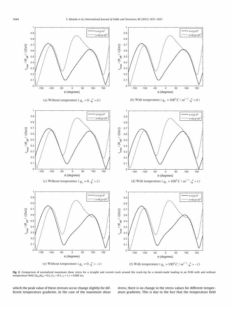
variation of stress fields under steady state thermo-mechanicalloading: maximum shear stress, circumferential tensile stress andmaximum principal stress. These stresses are normalized usingKeff =
ffiffiffiffiffiffiffiffiffi2prp
and plotted as a function of h (angle) around thecrack-tip. The variation of normalized maximum shear stress as afunction of curvature for both homogenous and FGM systems(f = 1 and f = �1 ) with and without the temperature field isshown in Fig. 2. The value of f = 1 denotes the increasing shearand mass density ahead of the crack tip and f = �1 denotes the re-verse situation. The nature of the variation of the normalized shearstress changes significantly with the incorporation of curvatureparameters but no significant variation was observed for differentnon-homogeneity values. For all the cases [(a)–(f)], when the cur-vature is introduced, the peak value of the maximum shear stressand the angle at which the maximum shear stress occurs changessignificantly.
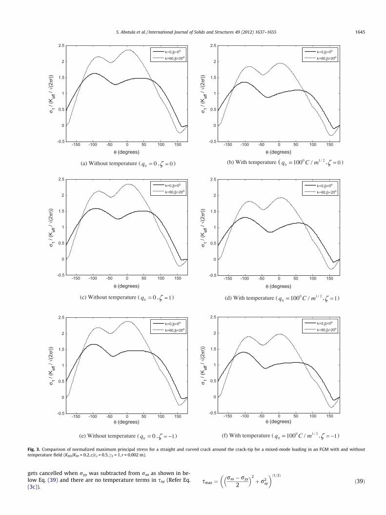
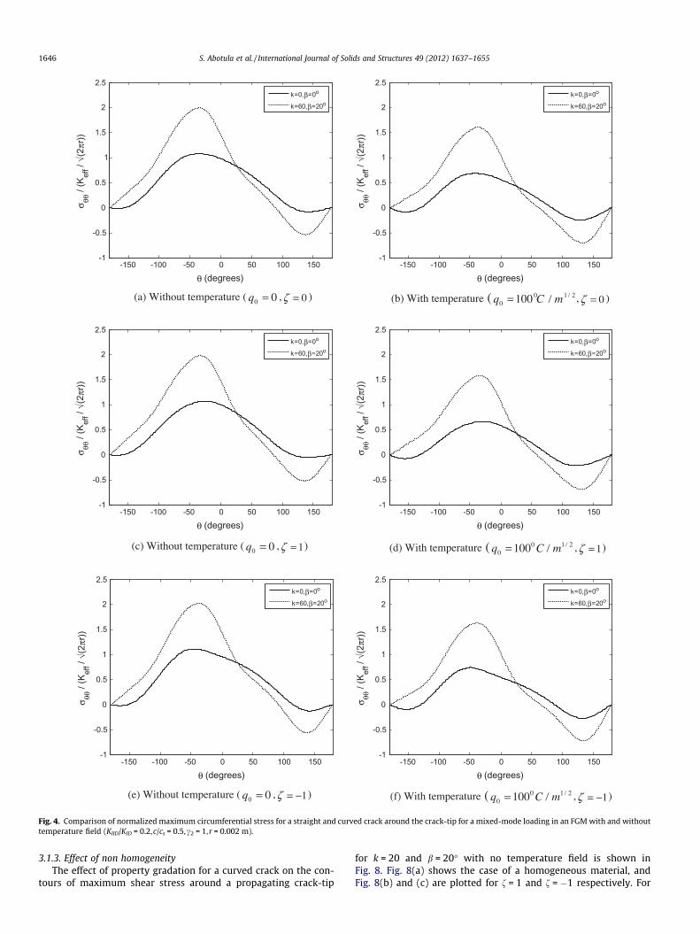
Angular variation of the normalized maximum principal stressand circumferential tensile stress as a function of curvature withand without the temperature field is plotted in Figs. 3 and 4 respec-tively. The peak value of the principal and circumferential tensilestresses increase significantly when the curvature is introducedfor both homogeneous and FGM systems and the increase in peakvalue of these stresses is approximately 50% higher for the case of acurved crack. Also the angle at which the peak values of thesestresses occur changes slightly with the addition of the curvatureparameters. As observed in the Figs. 2 and 3, the nature of variationof these normalized stresses changes significantly with the addi-tion of curvature terms.
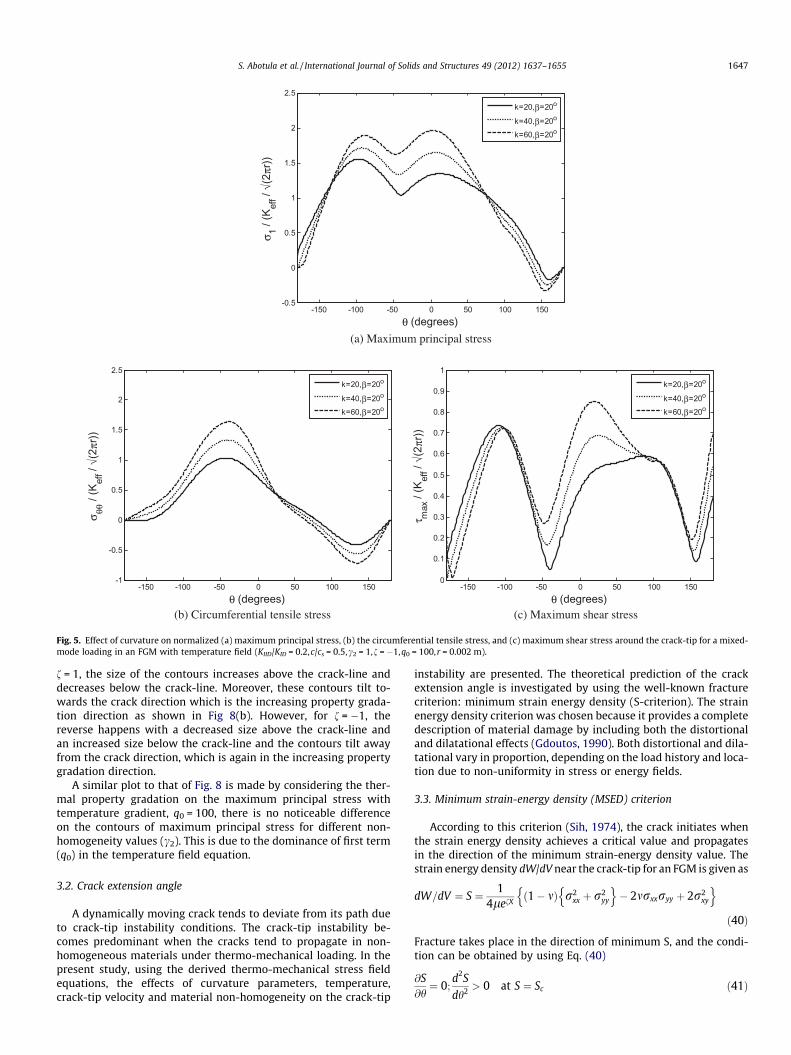
The angular variation of all three of the above normalizedstress components for a fixed value of the non-homogeneityparameter, f = �1, as a function of curvature with temperaturefield are shown in Fig. 5. As the local curvature of the crack path(k) increases, the peak values of these stresses increase while theangle at which the peak value of these stresses occur changesslightly for all the cases.
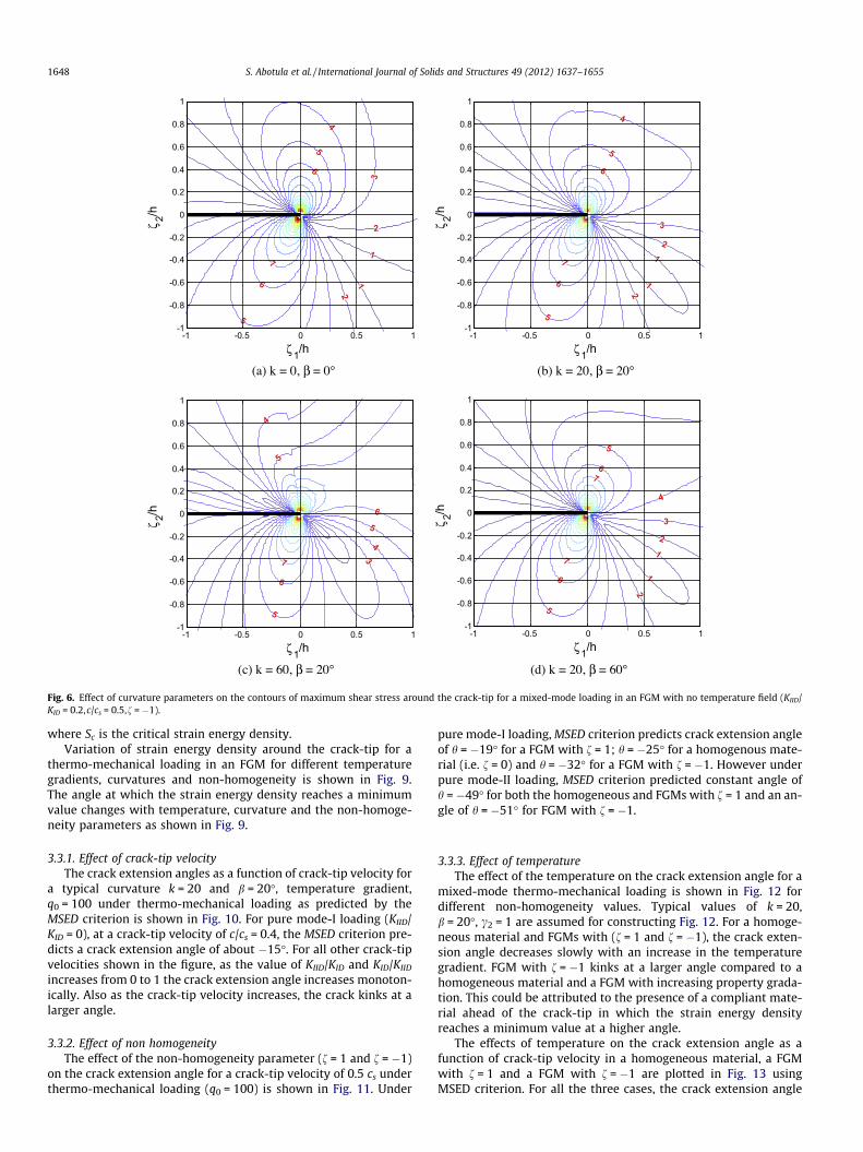
Fig. 6 shows the effect of the curvature on the contours of themaximum shear stress around the crack-tip with no temperaturefield for a mixed-mode loading in an FGM of f = �1 for four differ-ent curvature conditions. In Fig. 6(a), when curvature parametersare set to zero, standard asymmetric contours of mixed-modeloading as reported in literature, are obtained. The effect of curva-ture under mixed-mode loading is brought into effect in Fig. 6(b)by considering k = 20, b = 20�, and the figure shows that the num-ber and size of the shear stress contours increases with the addi-tion of curvature terms. If the angle between n1-axis and thefixed x-axis is kept constant (b = 20�) and the curvature is changedby three times as shown in Fig 6(c), the shear stress increases sig-nificantly and the stress contours tilt away from the crack direc-tion. However, if we keep the curvature value constant at k = 20and change the angle b to 60�, the shear stress contours tilt to-wards the crack direction, but there is no significant change inthe size of shear stress contours. Hence, for cases discussed inthe following sections, a typical value of b = 20� is used in furtheranalysis.
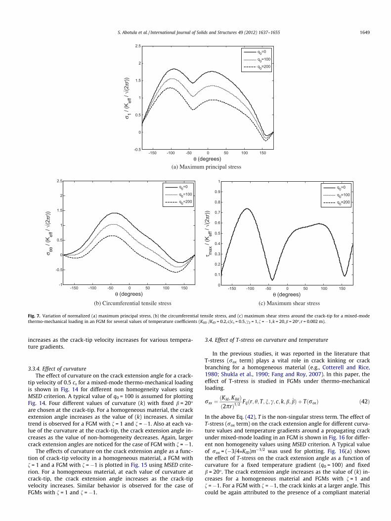
3.1.2. Effect of temperatureVariation of the normalized maximum principal stress, circum-
ferential stress and the maximum shear stress, is plotted aroundthe crack-tip for different temperature gradients (q0 = 0,q0 = 100and q0 = 200) as shown in Fig. 7. As the temperature gradient in-creases, the peak value of both the normalized maximum principalstress and circumferential tensile stress decreases and the angles at
-150 -100 -50 0 50 100 1500
0.1
0.2
0.3
0.4
0.5
0.6
0.7
0.8
0.9
1
τ max
/ (K
eff /
√(2 π
r))
θ (degrees)
k=0,β=0o
k=60,β=20o
(c) Without temperature ( 00 =q , 1=ζ ) (d) With temperature ( 2100 100 /m/Cq = , 1=ζ )
(b) With temperature ( 2100 100 /m/Cq = , 0=ζ )
(f) With temperature ( 2100 100 /m/Cq = , 1−=ζ )
(a) Without temperature ( 00 =q , 0=ζ )
(e) Without temperature ( 00 =q , 1−=ζ )
-150 -100 -50 0 50 100 1500
0.1
0.2
0.3
0.4
0.5
0.6
0.7
0.8
0.9
1τ m
ax /
(Kef
f / √(
2 πr))
θ (degrees)
k=0,β=0o
k=60,β=20o
-150 -100 -50 0 50 100 1500
0.1
0.2
0.3
0.4
0.5
0.6
0.7
0.8
0.9
1
τ max
/ (K
eff /
√(2 π
r))
θ (degrees)
k=0,β=0o
k=60,β=20o
-150 -100 -50 0 50 100 1500
0.1
0.2
0.3
0.4
0.5
0.6
0.7
0.8
0.9
1
τ max
/ (K
eff /
√(2 π
r))
θ (degrees)
k=0,β=0o
k=60,β=20o
-150 -100 -50 0 50 100 1500
0.1
0.2
0.3
0.4
0.5
0.6
0.7
0.8
0.9
1
τ max
/ (K
eff /
√(2 π
r))
θ (degrees)
k=0,β=0o
k=60,β=20o
-150 -100 -50 0 50 100 1500
0.1
0.2
0.3
0.4
0.5
0.6
0.7
0.8
0.9
1
τ max
/ (K
eff /
√(2 π
r))
θ (degrees)
k=0,β=0o
k=60,β=20o
Fig. 2. Comparison of normalized maximum shear stress for a straight and curved crack around the crack-tip for a mixed-mode loading in an FGM with and withouttemperature field (KIID/KID = 0.2,c/cs = 0.5,c2 = 1, r = 0.002 m).
1644 S. Abotula et al. / International Journal of Solids and Structures 49 (2012) 1637–1655
which the peak value of these stresses occur change slightly for dif-ferent temperature gradients. In the case of the maximum shear
stress, there is no change in the stress values for different temper-ature gradients. This is due to the fact that the temperature field
2
(a) Without temperature ( 00 =q , 0=ζ )
-150 -100 -50 0 50 100 150-0.5
0
0.5
1
1.5
2
2.5σ 1 /
(Kef
f / √(
2 πr))
θ (degrees)
k=0,β=0o
k=60,β=20o
-150 -100 -50 0 50 100 150-0.5
0
0.5
1
1.5
2
2.5
σ 1 / (K
eff /
√(2 π
r))
θ (degrees)
k=0,β=0o
k=60,β=20o
-150 -100 -50 0 50 100 150-0.5
0
0.5
1
1.5
2
2.5
σ 1 / (K
eff /
√(2 π
r))
θ (degrees)
k=0,β=0o
k=60,β=20o
-150 -100 -50 0 50 100 150-0.5
0
0.5
1
1.5
2
2.5
σ 1 / (K
eff /
√(2 π
r))
θ (degrees)
k=0,β=0o
k=60,β=20o
-150 -100 -50 0 50 100 150-0.5
0
0.5
1
1.5
2
2.5
σ 1 / (K
eff /
√(2 π
r))
θ (degrees)
k=0,β=0o
k=60,β=20o
-150 -100 -50 0 50 100 150-0.5
0
0.5
1
1.5
2
2.5
σ 1 / (K
eff /
√(2 π
r))
θ (degrees)
k=0,β=0o
k=60,β=20o
(c) Without temperature ( 00 =q , 1=ζ )
(e) Without temperature ( 00 =q , 1−=ζ ) (f) With temperature ( 2100 100 /m/Cq = , 1−=ζ )
(d) With temperature ( 2100 100 /m/Cq = , 1=ζ )
(b) With temperature ( 2100 100 /m/Cq = , 0=ζ )
Fig. 3. Comparison of normalized maximum principal stress for a straight and curved crack around the crack-tip for a mixed-mode loading in an FGM with and withouttemperature field (KIID/KID = 0.2,c/cs = 0.5,c2 = 1,r = 0.002 m).
S. Abotula et al. / International Journal of Solids and Structures 49 (2012) 1637–1655 1645
gets cancelled when ryy was subtracted from rxx as shown in be-low Eq. (39) and there are no temperature terms in sxy (Refer Eq.(3c)).
smax ¼rxx � ryy� �2
þ r2xy
� �ð1=2Þ
ð39Þ
(a) Without temperature ( 00 =q , 0=ζ )
-150 -100 -50 0 50 100 150-1
-0.5
0
0.5
1
1.5
2
2.5σ θθ
/ (K
eff /
√(2 π
r))
θ (degrees)
k=0,β=0o
k=60,β=20o
-150 -100 -50 0 50 100 150-1
-0.5
0
0.5
1
1.5
2
2.5
σ θθ /
(Kef
f / √(
2 πr))
θ (degrees)
k=0,β=0o
k=60,β=20o
-150 -100 -50 0 50 100 150-1
-0.5
0
0.5
1
1.5
2
2.5
σ θθ /
(Kef
f / √(
2 πr))
θ (degrees)
k=0,β=0o
k=60,β=20o
-150 -100 -50 0 50 100 150-1
-0.5
0
0.5
1
1.5
2
2.5
σ θθ /
(Kef
f / √(
2 πr))
θ (degrees)
k=0,β=0o
k=60,β=20o
-150 -100 -50 0 50 100 150-1
-0.5
0
0.5
1
1.5
2
2.5
σ θθ /
(Kef
f / √(
2 πr))
θ (degrees)
k=0,β=0o
k=60,β=20o
-150 -100 -50 0 50 100 150-1
-0.5
0
0.5
1
1.5
2
2.5
σ θθ /
(Kef
f / √(
2 πr))
θ (degrees)
k=0,β=0o
k=60,β=20o
(c) Without temperature ( 00 =q , 1=ζ )
(e) Without temperature ( 00 =q , 1−=ζ ) (f) With temperature ( 2100 100 /m/Cq = , 1−=ζ )
(d) With temperature ( 2100 100 /m/Cq = , 1=ζ )
(b) With temperature ( 2100 100 /m/Cq = , 0=ζ )
Fig. 4. Comparison of normalized maximum circumferential stress for a straight and curved crack around the crack-tip for a mixed-mode loading in an FGM with and withouttemperature field (KIID/KID = 0.2,c/cs = 0.5,c2 = 1, r = 0.002 m).
1646 S. Abotula et al. / International Journal of Solids and Structures 49 (2012) 1637–1655
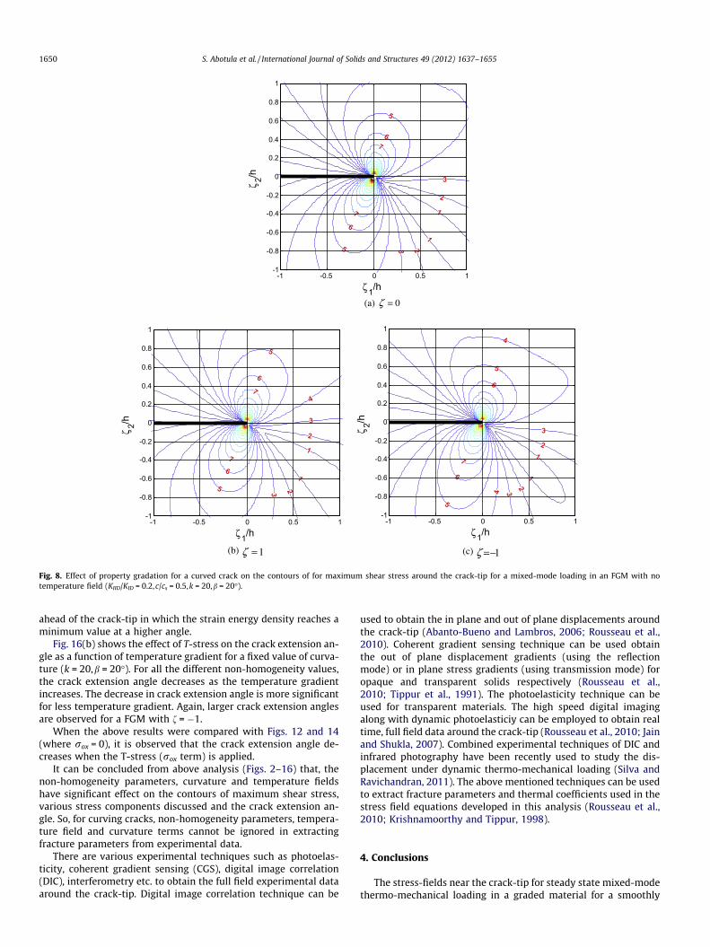
3.1.3. Effect of non homogeneityThe effect of property gradation for a curved crack on the con-
tours of maximum shear stress around a propagating crack-tip
for k = 20 and b = 20� with no temperature field is shown inFig. 8. Fig. 8(a) shows the case of a homogeneous material, andFig. 8(b) and (c) are plotted for f = 1 and f = �1 respectively. For
(b) Circumferential tensile stress (c) Maximum shear stress
(a) Maximum principal stress
-150 -100 -50 0 50 100 150-1
-0.5
0
0.5
1
1.5
2
2.5
σ θθ /
(Kef
f / √(
2 πr))
θ (degrees)
k=20,β=20o
k=40,β=20o
k=60,β=20o
-150 -100 -50 0 50 100 150-0.5
0
0.5
1
1.5
2
2.5
σ 1 / (K
eff /
√(2 π
r))
θ (degrees)
k=20,β=20o
k=40,β=20o
k=60,β=20o
-150 -100 -50 0 50 100 1500
0.1
0.2
0.3
0.4
0.5
0.6
0.7
0.8
0.9
1
τ max
/ (K
eff /
√(2 π
r))
θ (degrees)
k=20,β=20o
k=40,β=20o
k=60,β=20o
Fig. 5. Effect of curvature on normalized (a) maximum principal stress, (b) the circumferential tensile stress, and (c) maximum shear stress around the crack-tip for a mixed-mode loading in an FGM with temperature field (KIID/KID = 0.2,c/cs = 0.5,c2 = 1,f = �1,q0 = 100,r = 0.002 m).
S. Abotula et al. / International Journal of Solids and Structures 49 (2012) 1637–1655 1647
f = 1, the size of the contours increases above the crack-line anddecreases below the crack-line. Moreover, these contours tilt to-wards the crack direction which is the increasing property grada-tion direction as shown in Fig 8(b). However, for f = �1, thereverse happens with a decreased size above the crack-line andan increased size below the crack-line and the contours tilt awayfrom the crack direction, which is again in the increasing propertygradation direction.
A similar plot to that of Fig. 8 is made by considering the ther-mal property gradation on the maximum principal stress withtemperature gradient, q0 = 100, there is no noticeable differenceon the contours of maximum principal stress for different non-homogeneity values (c2). This is due to the dominance of first term(q0) in the temperature field equation.
3.2. Crack extension angle
A dynamically moving crack tends to deviate from its path dueto crack-tip instability conditions. The crack-tip instability be-comes predominant when the cracks tend to propagate in non-homogeneous materials under thermo-mechanical loading. In thepresent study, using the derived thermo-mechanical stress fieldequations, the effects of curvature parameters, temperature,crack-tip velocity and material non-homogeneity on the crack-tip
instability are presented. The theoretical prediction of the crackextension angle is investigated by using the well-known fracturecriterion: minimum strain energy density (S-criterion). The strainenergy density criterion was chosen because it provides a completedescription of material damage by including both the distortionaland dilatational effects (Gdoutos, 1990). Both distortional and dila-tational vary in proportion, depending on the load history and loca-tion due to non-uniformity in stress or energy fields.
3.3. Minimum strain-energy density (MSED) criterion
According to this criterion (Sih, 1974), the crack initiates whenthe strain energy density achieves a critical value and propagatesin the direction of the minimum strain-energy density value. Thestrain energy density dW/dV near the crack-tip for an FGM is given as
dW=dV ¼ S ¼ 14lefX
ð1� mÞ r2xx þ r2
yy
n o� 2mrxxryy þ 2r2
xy
n oð40Þ
Fracture takes place in the direction of minimum S, and the condi-tion can be obtained by using Eq. (40)
@S@h¼ 0;
d2S
dh2 > 0 at S ¼ Sc ð41Þ
(a) k = 0, β = 0° (b) k = 20, β = 20°
(c) k = 60, β = 20° (d) k = 20, β = 60°
ζ 2/h
ζ1/h
5
6
7
4
5
6
3
2
1
1
2
-1 -0.5 0 0.5 1-1
-0.8
-0.6
-0.4
-0.2
0
0.2
0.4
0.6
0.8
1
ζ 2/h
ζ1/h
4
5
6
5
6
7
3
21
1
2
-1 -0.5 0 0.5 1-1
-0.8
-0.6
-0.4
-0.2
0
0.2
0.4
0.6
0.8
1
ζ 2/h
ζ1/h
5
6
7
4
5
6
5
4
3
-1 -0.5 0 0.5 1-1
-0.8
-0.6
-0.4
-0.2
0
0.2
0.4
0.6
0.8
1
ζ 2/h
ζ1/h
5
6
7
5
67
4
3
2
2
1
1
-1 -0.5 0 0.5 1-1
-0.8
-0.6
-0.4
-0.2
0
0.2
0.4
0.6
0.8
1
Fig. 6. Effect of curvature parameters on the contours of maximum shear stress around the crack-tip for a mixed-mode loading in an FGM with no temperature field (KIID/KID = 0.2,c/cs = 0.5,f = �1).
1648 S. Abotula et al. / International Journal of Solids and Structures 49 (2012) 1637–1655
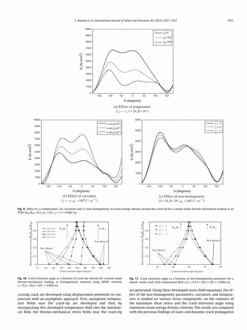
where Sc is the critical strain energy density.Variation of strain energy density around the crack-tip for a
thermo-mechanical loading in an FGM for different temperaturegradients, curvatures and non-homogeneity is shown in Fig. 9.The angle at which the strain energy density reaches a minimumvalue changes with temperature, curvature and the non-homoge-neity parameters as shown in Fig. 9.
3.3.1. Effect of crack-tip velocityThe crack extension angles as a function of crack-tip velocity for
a typical curvature k = 20 and b = 20�, temperature gradient,q0 = 100 under thermo-mechanical loading as predicted by theMSED criterion is shown in Fig. 10. For pure mode-I loading (KIID/KID = 0), at a crack-tip velocity of c/cs = 0.4, the MSED criterion pre-dicts a crack extension angle of about �15�. For all other crack-tipvelocities shown in the figure, as the value of KIID/KID and KID/KIID
increases from 0 to 1 the crack extension angle increases monoton-ically. Also as the crack-tip velocity increases, the crack kinks at alarger angle.
3.3.2. Effect of non homogeneityThe effect of the non-homogeneity parameter (f = 1 and f = �1)
on the crack extension angle for a crack-tip velocity of 0.5 cs underthermo-mechanical loading (q0 = 100) is shown in Fig. 11. Under
pure mode-I loading, MSED criterion predicts crack extension angleof h = �19� for a FGM with f = 1; h = �25� for a homogenous mate-rial (i.e. f = 0) and h = �32� for a FGM with f = �1. However underpure mode-II loading, MSED criterion predicted constant angle ofh = �49� for both the homogeneous and FGMs with f = 1 and an an-gle of h = �51� for FGM with f = �1.
3.3.3. Effect of temperatureThe effect of the temperature on the crack extension angle for a
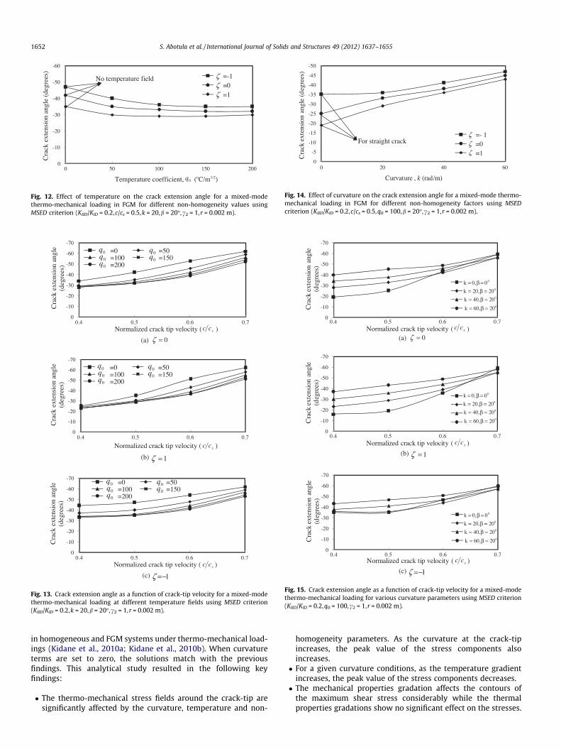
mixed-mode thermo-mechanical loading is shown in Fig. 12 fordifferent non-homogeneity values. Typical values of k = 20,b = 20�, c2 = 1 are assumed for constructing Fig. 12. For a homoge-neous material and FGMs with (f = 1 and f = �1), the crack exten-sion angle decreases slowly with an increase in the temperaturegradient. FGM with f = �1 kinks at a larger angle compared to ahomogeneous material and a FGM with increasing property grada-tion. This could be attributed to the presence of a compliant mate-rial ahead of the crack-tip in which the strain energy densityreaches a minimum value at a higher angle.
The effects of temperature on the crack extension angle as afunction of crack-tip velocity in a homogeneous material, a FGMwith f = 1 and a FGM with f = �1 are plotted in Fig. 13 usingMSED criterion. For all the three cases, the crack extension angle
(a) Maximum principal stress
(b) Circumferential tensile stress (c) Maximum shear stress
-150 -100 -50 0 50 100 150-1
-0.5
0
0.5
1
1.5
2
2.5
σ θθ /
(Kef
f / √(
2 πr))
θ (degrees)
q0=0
q0=100
q0=200
-150 -100 -50 0 50 100 150-0.5
0
0.5
1
1.5
2
2.5
σ 1 / (K
eff /
√(2 π
r))
θ (degrees)
q0=0
q0=100
q0=200
-150 -100 -50 0 50 100 1500
0.1
0.2
0.3
0.4
0.5
0.6
0.7
0.8
0.9
1
τ max
/ (K
eff /
√(2 π
r))
θ (degrees)
q0=0
q0=100
q0=200
Fig. 7. Variation of normalized (a) maximum principal stress, (b) the circumferential tensile stress, and (c) maximum shear stress around the crack-tip for a mixed-modethermo-mechanical loading in an FGM for several values of temperature coefficients (KIID /KID = 0.2,c/cs = 0.5,c2 = 1,f = �1,k = 20,b = 20�,r = 0.002 m).
S. Abotula et al. / International Journal of Solids and Structures 49 (2012) 1637–1655 1649
increases as the crack-tip velocity increases for various tempera-ture gradients.
3.3.4. Effect of curvatureThe effect of curvature on the crack extension angle for a crack-
tip velocity of 0.5 cs for a mixed-mode thermo-mechanical loadingis shown in Fig. 14 for different non homogeneity values usingMSED criterion. A typical value of q0 = 100 is assumed for plottingFig. 14. Four different values of curvature (k) with fixed b = 20�are chosen at the crack-tip. For a homogeneous material, the crackextension angle increases as the value of (k) increases. A similartrend is observed for a FGM with f = 1 and f = �1. Also at each va-lue of the curvature at the crack-tip, the crack extension angle in-creases as the value of non-homogeneity decreases. Again, largercrack extension angles are noticed for the case of FGM with f = �1.
The effects of curvature on the crack extension angle as a func-tion of crack-tip velocity in a homogeneous material, a FGM withf = 1 and a FGM with f = �1 is plotted in Fig. 15 using MSED crite-rion. For a homogeneous material, at each value of curvature atcrack-tip, the crack extension angle increases as the crack-tipvelocity increases. Similar behavior is observed for the case ofFGMs with f = 1 and f = �1.
3.4. Effect of T-stress on curvature and temperature
In the previous studies, it was reported in the literature thatT-stress (rox term) plays a vital role in crack kinking or crackbranching for a homogeneous material (e.g., Cotterell and Rice,1980; Shukla et al., 1990; Fang and Roy, 2007). In this paper, theeffect of T-stress is studied in FGMs under thermo-mechanicalloading.
rxx ¼ðKId;KIIdÞð2prÞ1=2 Fijðr; h; T; n; c; c; k;b; _bÞ þ TðroxÞ ð42Þ
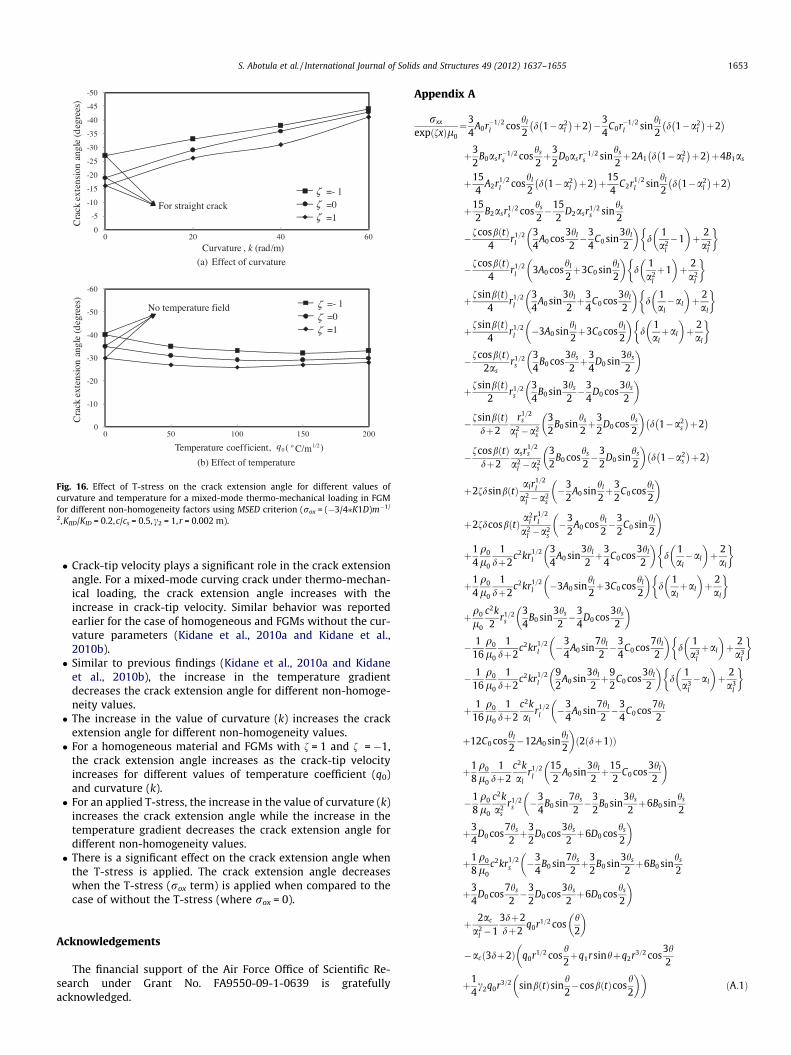
In the above Eq. (42), T is the non-singular stress term. The effect ofT-stress (rox term) on the crack extension angle for different curva-ture values and temperature gradients around a propagating crackunder mixed-mode loading in an FGM is shown in Fig. 16 for differ-ent non homogeneity values using MSED criterion. A Typical valueof rox = (�3/4⁄KID)m�1/2 was used for plotting. Fig. 16(a) showsthe effect of T-stress on the crack extension angle as a function ofcurvature for a fixed temperature gradient (q0 = 100) and fixedb = 20�. The crack extension angle increases as the value of (k) in-creases for a homogeneous material and FGMs with f = 1 andf = �1. For a FGM with f = �1, the crack kinks at a larger angle. Thiscould be again attributed to the presence of a compliant material
(a) 0=ζ
(b) 1=ζ (c) 1−=ζ
ζ 2/h
ζ1/h
5
6
7
5
67
3
2
1
123
-1 -0.5 0 0.5 1-1
-0.8
-0.6
-0.4
-0.2
0
0.2
0.4
0.6
0.8
1
ζ 2/h
ζ1/h
5
67
5
6
74
3
2
1
123
-1 -0.5 0 0.5 1-1
-0.8
-0.6
-0.4
-0.2
0
0.2
0.4
0.6
0.8
1
ζ 2/h
ζ1/h
5
6
7
4
5
6
3
21
1
234
-1 -0.5 0 0.5 1-1
-0.8
-0.6
-0.4
-0.2
0
0.2
0.4
0.6
0.8
1
Fig. 8. Effect of property gradation for a curved crack on the contours of for maximum shear stress around the crack-tip for a mixed-mode loading in an FGM with notemperature field (KIID/KID = 0.2,c/cs = 0.5,k = 20,b = 20�).
1650 S. Abotula et al. / International Journal of Solids and Structures 49 (2012) 1637–1655
ahead of the crack-tip in which the strain energy density reaches aminimum value at a higher angle.
Fig. 16(b) shows the effect of T-stress on the crack extension an-gle as a function of temperature gradient for a fixed value of curva-ture (k = 20,b = 20�). For all the different non-homogeneity values,the crack extension angle decreases as the temperature gradientincreases. The decrease in crack extension angle is more significantfor less temperature gradient. Again, larger crack extension anglesare observed for a FGM with f = �1.
When the above results were compared with Figs. 12 and 14(where rox = 0), it is observed that the crack extension angle de-creases when the T-stress (rox term) is applied.
It can be concluded from above analysis (Figs. 2–16) that, thenon-homogeneity parameters, curvature and temperature fieldshave significant effect on the contours of maximum shear stress,various stress components discussed and the crack extension an-gle. So, for curving cracks, non-homogeneity parameters, tempera-ture field and curvature terms cannot be ignored in extractingfracture parameters from experimental data.
There are various experimental techniques such as photoelas-ticity, coherent gradient sensing (CGS), digital image correlation(DIC), interferometry etc. to obtain the full field experimental dataaround the crack-tip. Digital image correlation technique can be
used to obtain the in plane and out of plane displacements aroundthe crack-tip (Abanto-Bueno and Lambros, 2006; Rousseau et al.,2010). Coherent gradient sensing technique can be used obtainthe out of plane displacement gradients (using the reflectionmode) or in plane stress gradients (using transmission mode) foropaque and transparent solids respectively (Rousseau et al.,2010; Tippur et al., 1991). The photoelasticity technique can beused for transparent materials. The high speed digital imagingalong with dynamic photoelasticiy can be employed to obtain realtime, full field data around the crack-tip (Rousseau et al., 2010; Jainand Shukla, 2007). Combined experimental techniques of DIC andinfrared photography have been recently used to study the dis-placement under dynamic thermo-mechanical loading (Silva andRavichandran, 2011). The above mentioned techniques can be usedto extract fracture parameters and thermal coefficients used in thestress field equations developed in this analysis (Rousseau et al.,2010; Krishnamoorthy and Tippur, 1998).
4. Conclusions
The stress-fields near the crack-tip for steady state mixed-modethermo-mechanical loading in a graded material for a smoothly
-150 -100 -50 0 50 100 1500
1000
2000
3000
4000
5000
6000
S (N
.m/m
3 )
θ (degrees)
ζ = -1ζ = 0ζ = 1
(b) Effect of curvature ( 1−=ζ , 210
0 100 /m/Cq = )
(a) Effect of temperature ( 1−=ζ , k = 20, β = 20°)
(c) Effect of non-homogeneity (k = 20, β = 20°, 210
0 100 /m/Cq = )
-150 -100 -50 0 50 100 1500
1000
2000
3000
4000
5000
6000
7000
8000
9000
10000
S (N
.m/m
3 )
θ (degrees)
k=20,β=20o
k=40,β=20o
k=60,β=20o
-150 -100 -50 0 50 100 1500
1000
2000
3000
4000
5000
6000
7000
8000
9000
10000
S (N
.m/m
3 )
θ (degrees)
q0=0
q0=100
q0=200
Fig. 9. Effect of (a) temperature, (b) curvature and (c) non-homogeneity on strain energy density around the crack-tip for a mixed mode thermo-mechanical loading in anFGM (KIID/KID = 0.2,c/cs = 0.5,c2 = 1,r = 0.002 m).
0
0.2
0.4
0.6
0.8
1
Str
ess
inte
nsit
y fa
ctor
rat
io
Crack extension angle (degrees)
C/Cs = 0.4
C/Cs = 0.5
C/Cs = 0.6
C/Cs = 0.7
Pure Mode-I
Pure Mode-II
III /KKIII /KK
Fig. 10. Crack extension angle as a function of crack-tip velocity for a mixed-modethermo-mechanical loading in homogeneous material using MSED criterion(f = 0,k = 20,b = 20�,r = 0.002 m).
0
0.2
0.4
0.6
0.8
1
-90-70-50-30-10
Str
ess
inte
nsit
y fa
ctor
rat
io
Crack extension angle (degrees)
-1
0
1
Pure Mode-I
III /KKIII/KK
=ζ=ζ=ζ
Pure Mode-II
Fig. 11. Crack extension angle as a function of non-homogeneity parameter for amixed- mode crack with temperature field (c/cs = 0.5,k = 20,b = 20�,r = 0.002 m).
S. Abotula et al. / International Journal of Solids and Structures 49 (2012) 1637–1655 1651
curving crack are developed using displacement potentials in con-junction with an asymptotic approach. First, asymptotic tempera-ture fields near the crack-tip are developed and then byincorporating this developed temperature field into the mechani-cal field, the thermo-mechanical stress fields near the crack-tip
are generated. Using these developed stress field equations, the ef-fect of the non-homogeneity parameters, curvature, and tempera-ture is studied on various stress components, on the contours ofthe maximum shear stress and the crack extension angle usingminimum strain energy density criterion. The results are comparedwith the previous findings of static and dynamic crack propagation
Temperature coefficient, (oC/m1/2)0q
-60
-50
-40
-30
-20
-10
00 50 100 150 200
Cra
ck e
xten
sion
ang
le (
degr
ees) =-1
=0=1
No temperature field ζζζ
Fig. 12. Effect of temperature on the crack extension angle for a mixed-modethermo-mechanical loading in FGM for different non-homogeneity values usingMSED criterion (KIID/KID = 0.2,c/cs = 0.5,k = 20,b = 20�,c2 = 1,r = 0.002 m).
-50
-45
-40
-35
-30
-25
-20
-15
-10
-5
06040200
Cra
ck e
xten
sion
ang
le (
deg
rees
)
Curvature , k (rad/m)
=- 1=0=1
For straight crack
ζζζ
Fig. 14. Effect of curvature on the crack extension angle for a mixed-mode thermo-mechanical loading in FGM for different non-homogeneity factors using MSEDcriterion (KIID/KID = 0.2,c/cs = 0.5,q0 = 100,b = 20�,c2 = 1,r = 0.002 m).
(a) 0=ζ
(b) 1=ζ
(c) 1−=ζ
scc
-70
-60
-50
-40
-30
-20
-10
00.4 0.5 0.6 0.7
Cra
ck e
xten
sion
ang
le
(deg
rees
)
Normalized crack tip velocity ( )
=0 =50=100 =150=200
0q0q0q
0q0q
scc
-70
-60
-50
-40
-30
-20
-10
00.4 0.5 0.6 0.7
Cra
ck e
xten
sion
ang
le
(deg
rees
)
Normalized crack tip velocity ( )
=0 =50=100 =150=200
0q0q0q
0q0q
scc
-70
-60
-50
-40
-30
-20
-10
00.4 0.5 0.6 0.7
Cra
ck e
xten
sion
ang
le
(deg
rees
)
Normalized crack tip velocity ( )
=0 =50=100 =150=200
0q0q0q
0q0q
Fig. 13. Crack extension angle as a function of crack-tip velocity for a mixed-modethermo-mechanical loading at different temperature fields using MSED criterion(KIID/KID = 0.2,k = 20,b = 20�,c2 = 1, r = 0.002 m).
(a) 0=ζscc
-70
-60
-50
-40
-30
-20
-10
00.4 0.5 0.6 0.7
Cra
ck e
xten
sion
ang
le
(deg
rees
)
Normalized crack tip velocity ( )
00β0,k ==002β0,2k ==
002β0,6k ==
002β0,4k ==
scc
-70
-60
-50
-40
-30
-20
-10
00.4 0.5 0.6 0.7
Cra
ck e
xten
sion
ang
le
(deg
rees
)
Normalized crack tip velocity ( )
00β0,k ==002β0,2k ==
002β0,6k ==
002β0,4k ==
scc
-70
-60
-50
-40
-30
-20
-10
00.4 0.5 0.6 0.7
Cra
ck e
xten
sion
ang
le
(deg
rees
)
Normalized crack tip velocity ( )
00β0,k ==002β0,2k ==
002β0,6k ==
002β0,4k ==
(b) 1=ζ
(c) 1−=ζ
Fig. 15. Crack extension angle as a function of crack-tip velocity for a mixed-modethermo-mechanical loading for various curvature parameters using MSED criterion(KIID/KID = 0.2,q0 = 100,c2 = 1,r = 0.002 m).
1652 S. Abotula et al. / International Journal of Solids and Structures 49 (2012) 1637–1655
in homogeneous and FGM systems under thermo-mechanical load-ings (Kidane et al., 2010a; Kidane et al., 2010b). When curvatureterms are set to zero, the solutions match with the previousfindings. This analytical study resulted in the following keyfindings:
� The thermo-mechanical stress fields around the crack-tip aresignificantly affected by the curvature, temperature and non-
homogeneity parameters. As the curvature at the crack-tipincreases, the peak value of the stress components alsoincreases.� For a given curvature conditions, as the temperature gradient
increases, the peak value of the stress components decreases.� The mechanical properties gradation affects the contours of
the maximum shear stress considerably while the thermalproperties gradations show no significant effect on the stresses.
-50
-45
-40
-35
-30
-25
-20
-15
-10
-5
00604020
Cra
ck e
xten
sion
ang
le (
deg
rees
)
Curvature , k (rad/m)
=- 1=0=1
For straight crack ζζζ
-60
-50
-40
-30
-20
-10
00 50 100 150 200
Cra
ck e
xten
sion
ang
le (
deg
rees
)
Temperature coefficient, ( )
=- 1=0=1
0q 1/2o C/m
ζζζ
No temperature field
(a) Effect of curvature
(b) Effect of temperature
Fig. 16. Effect of T-stress on the crack extension angle for different values ofcurvature and temperature for a mixed-mode thermo-mechanical loading in FGMfor different non-homogeneity factors using MSED criterion (rox = (�3/4⁄K1D)m�1/
2,KIID/KID = 0.2,c/cs = 0.5,c2 = 1,r = 0.002 m).
S. Abotula et al. / International Journal of Solids and Structures 49 (2012) 1637–1655 1653
� Crack-tip velocity plays a significant role in the crack extensionangle. For a mixed-mode curving crack under thermo-mechan-ical loading, the crack extension angle increases with theincrease in crack-tip velocity. Similar behavior was reportedearlier for the case of homogeneous and FGMs without the cur-vature parameters (Kidane et al., 2010a and Kidane et al.,2010b).� Similar to previous findings (Kidane et al., 2010a and Kidane
et al., 2010b), the increase in the temperature gradientdecreases the crack extension angle for different non-homoge-neity values.� The increase in the value of curvature (k) increases the crack
extension angle for different non-homogeneity values.� For a homogeneous material and FGMs with f = 1 and f = �1,
the crack extension angle increases as the crack-tip velocityincreases for different values of temperature coefficient (q0)and curvature (k).� For an applied T-stress, the increase in the value of curvature (k)
increases the crack extension angle while the increase in thetemperature gradient decreases the crack extension angle fordifferent non-homogeneity values.� There is a significant effect on the crack extension angle when
the T-stress is applied. The crack extension angle decreaseswhen the T-stress (rox term) is applied when compared to thecase of without the T-stress (where rox = 0).
Acknowledgements
The financial support of the Air Force Office of Scientific Re-search under Grant No. FA9550-09-1-0639 is gratefullyacknowledged.
Appendix A
rxx
expðfxÞl0¼3
4A0r�1=2
l coshl
2d 1�a2
l
þ2
�3
4C0r�1=2
l sinhl
2d 1�a2
l
þ2
þ32
B0asr�1=2s cos
hs
2þ3
2D0asr�1=2
s sinhs
2þ2A1 d 1�a2
l
þ2
þ4B1as
þ154
A2r1=2l cos
hl
2d 1�a2
l
þ2
þ15
4C2r1=2
l sinhl
2d 1�a2
l
þ2
þ15
2B2asr1=2
s coshs
2�15
2D2asr1=2
s sinhs
2
�fcosbðtÞ4
r1=2l
34
A0 cos3hl
2�3
4C0 sin
3hl
2
� �d
1a2
l
�1� ��
þ 2a2
l
�
�fcosbðtÞ4
r1=2l 3A0 cos
hl
2þ3C0 sin
hl
2
� �d
1a2
l
þ1� �
þ 2a2
l
� �
þfsinbðtÞ4
r1=2l
34
A0 sin3hl
2þ3
4C0 cos
3hl
2
� �d
1al�al
� ��þ 2
al
�
þfsinbðtÞ4
r1=2l �3A0 sin
hl
2þ3C0 cos
hl
2
� �d
1alþal
� �þ 2
al
� �
�fcosbðtÞ2as
r1=2s
34
B0 cos3hs
2þ3
4D0 sin
3hs
2
� �
þfsinbðtÞ2
r1=2s
34
B0 sin3hs
2�3
4D0 cos
3hs
2
� �
�fsinbðtÞdþ2
r1=2s
a2l �a2
s
32
B0 sinhs
2þ3
2D0 cos
hs
2
� �d 1�a2
s
þ2
�fcosbðtÞdþ2
asr1=2s
a2l �a2
s
32
B0 coshs
2�3
2D0 sin
hs
2
� �d 1�a2
s
þ2
þ2fdsinbðtÞ alr1=2l
a2l �a2
s
�32
A0 sinhl
2þ3
2C0 cos
hl
2
� �
þ2fdcosbðtÞ a2l r1=2
l
a2l �a2
s
�32
A0 coshl
2�3
2C0 sin
hl
2
� �
þ14q0
l0
1dþ2
c2kr1=2l
34
A0 sin3hl
2þ3
4C0 cos
3hl
2
� �d
1al�al
� ��þ 2
al
�
þ14q0
l0
1dþ2
c2kr1=2l �3A0 sin
hl
2þ3C0 cos
hl
2
� �d
1alþal
� ��þ 2
al
�
þq0
l0
c2k2
r1=2s
34
B0 sin3hs
2�3
4D0 cos
3hs
2
� �
� 116
q0
l0
1dþ2
c2kr1=2l �3
4A0 sin
7hl
2�3
4C0 cos
7hl
2
� �d
1a3
l
þal
� ��þ 2
a3l
�
� 116
q0
l0
1dþ2
c2kr1=2l
92
A0 sin3hl
2þ9
2C0 cos
3hl
2
� �d
1a3
l
�al
� ��þ 2
a3l
�
þ 116
q0
l0
1dþ2
c2kal
r1=2l �3
4A0 sin
7hl
2�3
4C0 cos
7hl
2
�
þ12C0 coshl
2�12A0 sin
hl
2
�ð2ðdþ1ÞÞ
þ18q0
l0
1dþ2
c2kal
r1=2l
152
A0 sin3hl
2þ15
2C0 cos
3hl
2
� �
�18q0
l0
c2ka2
sr1=2
s �34
B0 sin7hs
2�3
2B0 sin
3hs
2þ6B0 sin
hs
2
�
þ34
D0 cos7hs
2þ3
2D0 cos
3hs
2þ6D0 cos
hs
2
�
þ18q0
l0c2kr1=2
s �34
B0 sin7hs
2þ3
2B0 sin
3hs
2þ6B0 sin
hs
2
�
þ34
D0 cos7hs
2�3
2D0 cos
3hs
2þ6D0 cos
hs
2
�
þ 2ac
a2l �1
3dþ2dþ2
q0r1=2 cosh2
� �
�acð3dþ2Þ q0r1=2 cosh2þq1rsinhþq2r3=2 cos
3h2
�
þ14c2q0r3=2 sinbðtÞsin
h2�cosbðtÞcos
h2
� ��ðA:1Þ
1654 S. Abotula et al. / International Journal of Solids and Structures 49 (2012) 1637–1655
ryy
expðfxÞl0¼ 3
4A0r�1=2
l coshl
2d� a2
l ðdþ 2Þ
� 34
C0r�1=2l sin
hl
2d� a2
l ðdþ 2Þ
� 32
B0asr�1=2s cos
hs
2� 3
2D0asr�1=2
s sinhs
2þ 2A1 d� a2
l ðdþ 2Þ
� 4B1as þ154
A2r1=2l cos
hl
2d� a2
l ðdþ 2Þ
þ 154
C2r1=2l sin
hl
2d� a2
l ðdþ 2Þ
� 152
B2asr1=2s cos
hs
2þ 15
2D2asr1=2
s sinhs
2
� f cos bðtÞ4
r1=2l
34
A0 cos3hl
2� 3
4C0 sin
3hl
2
� �d
a2l
� ðdþ 2Þ� �
� f cos bðtÞ4
r1=2l 3A0 cos
hl
2þ 3C0 sin
hl
2
� �d
a2l
þ ðdþ 2Þ� �
þ f sin bðtÞ4
r1=2l
34
A0 sin3hl
2þ 3
4C0 cos
3hl
2
� �dal� alðdþ 2Þ
� �
þ f sin bðtÞ4
r1=2l �3A0 sin
hl
2þ 3C0 cos
hl
2
� �dalþ alðdþ 2Þ
� �
þ f cos bðtÞ2as
r1=2s
34
B0 cos3hs
2þ 3
4D0 sin
3hs
2
� �
� f sin bðtÞ2
r1=2s
34
B0 sin3hs
2� 3
4D0 cos
3hs
2
� �
� f sin bðtÞdþ 2
r1=2s
a2l � a2
s
32
B0 sinhs
2þ 3
2D0 cos
hs
2
� �d� a2
s ðdþ 2Þ
� f cos bðtÞdþ 2
asr1=2s
a2l � a2
s
32
B0 coshs
2� 3
2D0 sin
hs
2
� �d� a2
s ðdþ 2Þ
� 2fd sin bðtÞ alr1=2l
a2l � a2
s
�32
A0 sinhl
2þ 3
2C0 cos
hl
2
� �
� 2fd cos bðtÞ a2l r1=2
l
a2l � a2
s
�32
A0 coshl
2� 3
2C0 sin
hl
2
� �
þ 14
q0
l0
1dþ 2
c2kr1=2l
34
A0 sin3hl
2þ 3
4C0 cos
3hl
2
� �dal� alðdþ 2Þ
� �
þ 14
q0
l0
1dþ 2
c2kr1=2l �3A0 sin
hl
2þ 3C0 cos
hl
2
� �dalþ alðdþ 2Þ
� �
� q0
l0
c2k2
r1=2s
34
B0 sin3hs
2� 3
4D0 cos
3hs
2
� �
� 116
q0
l0
1dþ 2
c2kr1=2l �3
4A0 sin
7hl
2� 3
4C0 cos
7hl
2
� �d
a3l
þ alðdþ 2Þ� �
� 116
q0
l0
1dþ 2
c2kr1=2l
92
A0 sin3hl
2þ 9
2C0 cos
3hl
2
� �d
a3l
� alðdþ 2Þ� �
þ 116
q0
l0
1dþ 2
c2kal
r1=2l
� �34
A0 sin7hl
2� 3
4C0 cos
7hl
2þ 12C0 cos
hl
2� 12A0 sin
hl
2
� �ð2ðdþ 1ÞÞ
� 18
q0
l0
1dþ 2
c2kal
r1=2l
152
A0 sin3hl
2þ 15
2C0 cos
3hl
2
� �þ 1
8q0
l0
c2ka2
sr1=2
s
� �34
B0 sin7hs
2� 3
2B0 sin
3hs
2þ 6B0 sin
hs
2þ 3
4D0 cos
7hs
2
�
þ 32
D0 cos3hs
2þ6D0 cos
hs
2
�� 1
8q0
l0c2kr1=2
s
� �34
B0 sin7hs
2þ 3
2B0 sin
3hs
2þ 6B0 sin
hs
2þ 3
4D0 cos
7hs
2
�
�32
D0 cos3hs
2þ 6D0 cos
hs
2
�
� 2ac
a2l � 1
3dþ 2dþ 2
q0r1=2 cosh2
� �
� acð3dþ 2Þ q0r1=2 cosh2þ q1r sin hþ q2r3=2 cos
3h2
�
þ14c2q0r3=2 sin bðtÞ sin
h2� cos bðtÞ cos
h2
� ��ðA:2Þ
syy
expðfxÞl0¼ 3
2A0alr
�1=2l sin
hl
2þ 3
2C0alr
�1=2l cos
hl
2þ 3
4B0r�1=2
s sinhs
21þ a2
s
� 34
D0r�1=2s cos
hs
21þ a2
s
� 2A1al � 2B1 þ 2C1a1 � 2D1a2
s
� 152
A2alr1=2l sin
hl
2þ 15
2C2alr
1=2l cos
hl
2� 15
4B2r1=2
s sinhs
21þ a2
s
� 15
4D2r1=2
s coshs
21þ a2
s
� f cos bðtÞ
2alr1=2
l
34
A0 sin3hl
2þ 3
4C0 cos
3hl
2
� �
� f cos bðtÞ4
r1=2s 3B0 sin
hs
2þ 3D0 cos
hs
2
� �1� 1
a2s
� �
þ f sin bðtÞ2
r1=2l �3
4A0 cos
3hl
2þ 3
4C0 sin
3hl
2
� �
� f sin bðtÞ4
r1=2s
34
B0 cos3hs
2þ 3
4D0 sin
3hs
2
� �as þ
1as
� �
� f cos bðtÞ4
r1=2s
34
B0 sin3hs
2� 3
4D0 cos
3hs
2
� �1þ 1
a2s
� �
� f sin bðtÞ4
r1=2s 3B0 cos
hs
2� 3D0 sin
hs
2
� ��as þ
1as
� �
� f sin bðtÞdþ 2
asr1=2s
a2l � a2
s
3B0 coshs
2� 3D0 sin
hs
2
� �
þ f cos bðtÞdþ 2
a2s r1=2
s
a2l � a2
s
3B0 sinhs
2þ 3D0 cos
hs
2
� �
þ fd sin bðtÞ r1=2l
a2l � a2
s
�32
A0 coshl
2� 3
2C0 sin
hl
2
� �1þ a2
l
� fd cos bðtÞ alr1=2l
a2l � a2
s
�32
A0 sinhl
2þ 3
2C0 cos
hl
2
� �1þ a2
l
þ 14
q0
l0
1dþ 2
c2kr1=2l �3
2A0 cos
3hl
2þ 3
2C0 sin
3hl
2
� �
� 14
q0
l0c2kr1=2
s34
B0 cos3hs
2þ 3
4D0 sin
3hs
2
� �as þ
1as
� �
� 14
q0
l0c2kr1=2
s 3B0 coshs
2� 3D0 sin
hs
2
� ��as þ
1as
� �
� 18
q0
l0
1dþ 2
c2ka2
l
r1=2l
34
A0 cos7hl
2þ 3
2A0 cos
3hl
2þ 6A0 cos
hl
2
�
� 34
C0 sin7hl
2� 3
2C0 sin
3hl
2þ 6C0 sin
hl
2
�
þ 18
q0
l0
1dþ 2
c2kr1=2l
34
A0 cos7hl
2� 3
2A0 cos
3hl
2þ 6A0 cos
hl
2
�
�34
C0 sin7hl
2þ 3
2C0 sin
3hl
2þ 6C0 sin
hl
2
�
þ 18
q0
l0
c2kas
r1=2s �15
2B0 cos
3hs
2� 15
2D0 sin
3hs
2
� �
þ 116
q0
l0c2kr1=2
s34
B0 cos7hs
2þ 3
4D0 sin
7hs
2
� �� 1
a3sþ as
� �
þ 116
q0
l0c2kr1=2
s92
B0 cos3hs
2þ 9
2D0 sin
3hs
2
� �1a3
sþ as
� �
� 2ac
a2l � 1
3dþ 2dþ 2
q0r1=2 sinh2
� �ðA:3Þ
References
Abanto-Bueno, J., Lambros, J., 2006. An experimental study of mixed mode crackinitiation and growth in functionally graded materials. Exp. Mech. 46 (2), 179–196.
Atkinson, C., List, R.D., 1978. Steady state crack propagation into media withspatially varying elastic properties. Int. J. Eng. Sci. 16, 717–730.
S. Abotula et al. / International Journal of Solids and Structures 49 (2012) 1637–1655 1655
Awrejcewicz, J., Krys’ko, V.A., 2003. Nonclassical thermoelastic problems innonlinear dynamic of shells. Applications of the Bubnov–Galerkin and FiniteDifference Numerical Methods. Springer, Germany.
Brischetto, S., Carrera, E., 2010. Coupled thermo-mechanical analysis of one-layeredand multilayered plates. Compos. Struct. 92, 1793–1812.
Chalivendra, V.B., 2007. Asymptotic analysis of transient curved crack infunctionally graded materials. Int. J. Solids Struct. 44, 465–479.
Chalivendra, V.B., 2008. Mode-I crack-tip stress fields for inhomogeneousorthotropic medium. Mech. Mater. 40, 293–301.
Chalivendra, V.B., 2009. crack-tip stress fields for orthotropic functionally gradedmaterials. Acta Mech. 204 (1), 51–60.
Chalivendra, V.B., Shukla, A., 2005. Transient elastodynamic crack growth infunctionally graded materials. J. Appl. Mech. 72, 237–248.
Chalivendra, V.B., Shukla, A., Parameswaran, V., 2002. Dynamic out of planedisplacement fields for an inclined crack in graded materials. J. Elast. 69, 99–119.
Chalivendra, V.B., Shukla, A., Parameswaran, V., 2003. Quasi-static stress fields for acrack inclined to the property gradation in functionally graded materials. ActaMech. 162, 167–184.
Cotterell, B., Rice, J.R., 1980. Slightly curved or kinked cracks. Int. J. Fract. 16, 155–169.
Delale, F., Erdogan, F., 1983. The crack problem for a nonhomogeneous plane. J.Appl. Mech. 50, 67–80.
Drake, J.T., Williamson, R.L., Rabin, B.H., 1993. Finite element analysis of thermalresidual stresses at graded ceramic-metal interfaces. Part II: Interfaceoptimization for residual stress reduction. J. Appl. Phys. 74, 1321–1326.
Erdogan, F., Wu, B.H., 1996. Crack problems in FGM layers under thermal stresses. J.Therm. Stresses 19, 237–265.
Eslami, M.R., Shakeri, M., Sedaghati, R., 1994. Coupled thermoelasticity of axiallysymmetric cylindrical shells. J. Therm. Stresses 10, 564–576.
Fahrenhlotz, W.G., Hilmas, G.E., Talmy, I.G., Zaykoski, J.A., 2007. RefractoryDiborides of Zirconium and Hafnium. J. Am. Ceram. Soc. 90, 1347–1364.
Fang, L.X., Roy, X.L., 2007. T-stresses across static crack kinking. J. Appl. Mech. 74,181–190.
Freund, L.B., 1990. Dynamic Fracture Mechanics. Cambridge University Press,Cambridge.
Gdoutos, E.E., 1990. Fracture Mechanics Criteria and Applications. Kluwer AcademicPublishers.
Giannakopoulos, A.E., Suresh, S., Finot, M., Olsson, M., 1995. Elastoplastic analysis ofthermal cycling: layered materials with compositional gradient. Acta Metall.Mater. 43, 1335–1354.
Gu, P., Asaro, R.J., 1997. Cracks in functionally graded materials. Int. J. Solids Sruct.34 (1), 1–17.
Hasselman, D.P.H., Youngblood, G.E., 1978. Enhanced thermal stress resistance ofstructural ceramics with thermal conductivity gradient. J. Am. Ceram. Soc. 61,49–52.
Irwin, G.R., 1980. Series representation of the stress field around constant speedcracks. University of Maryland Lecture Notes, Maryland.
Jain, N., Shukla, A., 2007. Asymptotic analysis and reflection photoelasticity for thestudy of transient crack propagation in graded materials. J. Mech. Mater. Struct.2 (4), 595–612.
Jain, N., Shukla, A., Chona, R., 2006. Asymptotic stress fields for thermo-mechanically loaded cracks in FGMs. J. ASTM Int. 3 (7), 78–90.
Jiang, C.P., Zou, Z.Z., Wang, D., Liu, Y.W., 1991. A discussion about a class of stressintensity factors and its verification. Int. J. Fract. 49, 141–157.
Jin, Z.H., Batra, R.C., 1996. Stress intensity relaxation at the tip of an edge crack in afunctionally graded materials subjected to a thermal shock. J. Therm. Stresses19, 317–339.
Jin, Z.H., Noda, N., 1994. Crack-tip singular fields in nonhomogeneous materials. J.Appl. Mech. 61, 738–740.
Jin, Z.H., Paulino, G.H., 2001. Transient thermal stress analysis of an edge crack in afunctionally graded materials. Int. J. Fract. 107, 73–98.
Jin, G.H., Paulino, G.H., Dodds, R.H., 2002. Finite element investigation of quasi-static crack growth in functionally graded materials using a novel cohesive zonefracture model. J. ASME J. Appl. Mech. 69, 370–379.
Kawasaki, A., Wantanabe, R., 1987. Finite element analysis of thermal stress of themetal/ceramics multi-layer composites with controlled compositionalgradients. J. Jpn. Inst. Met. 51, 525–529.
Kidane, A., Chalivendra, V.B., Shukla, A., 2010a. Thermo-mechanical stress fields andstrain energy associated with a propagating crack. Acta Mech. 215 (1), 57–69.
Kidane, A., Chalivendra, V.B., Shukla, A., Chona, R., 2010b. Mixed-mode dynamiccrack propagation in graded materials under thermo-mechanical loading. Eng.Fract. Mech. 77 (14), 2864–2880.
Kim, J.H., Paulino, G.H., 2002. Finite element evaluation of stress intensity factors infunctionally graded materials. Int. J. Numer. Methods Eng. 53, 1903–1935.
Kirugulige, M.S., Tippur, H.V., 2008. Mixed-mode dynamic crack growth in afunctionally graded materials under mode-I thermomechanical loading. Int. J.Solids Struct. 75 (5), 1–14.
Konda, N., Erdogan, F., 1994. The mixed mode crack problem in a nonhomogeneouselastic plane. Eng. Fract. Mech. 47, 533–545.
Krishnamoorthy, H., Tippur, H.V., 1998. Extracting fracture parameters using localcollocation of full-field displacement data. Exp. Tech. 22 (1), 22–25.
Krishnaswamy, S., Tippur, H.V., Rosakis, A.J., 1992. Measurement of transient cracktip deformation fields using the method of coherent gradient sensing. J. Mech.Phys. Solids. 40, 339–372.
Kubair, D.V., Geubelle, P.H., Lambros, J., 2005. Analysis of a mode-3 stationary crackin a functionally graded material. J. Appl. Mech. Trans. ASME 72, 461–467.
Kuroda, Y., Kusaka, K., Moro, A., Togawa, M., 1993. Evaluation tests of ZrO2/Nifunctionally gradient materials for regeneratively cooled thrust engineapplications. In: Holt, J.B., Koisumi, M., Hirai, T., Munir, Z.A. (Eds.), CeramicTransactions. Functionally Gradient Materials, vol. 34. Am. Ceram. Soc.,Westerville, Ohio, pp. 289–296.
Lambros, J., Cheeseman, B.A., Santare, M.H., 2000. Experimental investigation of thequasi-static fracture of functionally graded materials. Int. J. Solids Struct. 37,3715–3732.
Lee, K.H., Chalivendra, V.B., Shukla, A., 2008. Dynamic crack-tip stress anddisplacement fields under thermomechanical loading in functionally gradedmaterials. J. Appl. Mech. 75 (5), 1–7.
Liu, C., Rosakis, A.J., 1994. On the higher order asymptotic analysis of a non-uniformly propagating dynamic crack along an arbitrary path. J. Elast. 35, 27–60.
McQuillen, E.J., Brull, M.A., 1970. Dynamic thermoelastic response of cylindricalshell. Trans. ASME, J. Appl. Mech. 37 (3), 661–670.
Niino, M., Hirai, T., Watanabe, R., 1987. The functionally gradient materials. J. Jpn.Soc. Compos. Mater. 13 (1), 257.
Noda, N., 1997. Thermal stress intensity for functionally graded plate with an edgecrack, J. Therm. Stresses 20, 373–387.
Noda, N., Ishihara, M., Yamamoto, N., Fujimoto, T., 2003. Two-crack propagation in afunctionally graded material plate under thermal loads. Mater. Sci. Forum, 607–612.
Nowinski, J.L., 1978. Theory of Thermoelasticity with Applications. Sijthoff &Noordhoff International Publications, The Netherlands.
Parameswaran, V., Shukla, A., 1999. Crack-tip stress fields for dynamic fracture infunctionally gradient materials. Mech. Mater. 31, 579–596.
Parameswaran, V., Shukla, A., 2002. Asymptotic stress fields for stationary cracksalong the gradient in functionally graded materials. J. Appl. Mech. 69, 240–243.
Rousseau, C.E., Tippur, H.V., 2001. Dynamic fracture of compositionally gradedmaterials with cracks along the elastic gradient: experiments and analysis.Mech. Mater. 33, 403–421.
Rousseau, C.E., Chalivendra, V.B., Tippur, H.V., Shukla, A., 2010. Experimentalfracture mechanics of functionally graded materials: an overview of opticalinvestigations. Exp. Mech. 50 (7), 845–865.
Sadd, M.H., 2009. Elasticity: Theory, Applications, and Numerics. Academic Press,Publications, Burlington, MA.
Schovanec, L., Walton, J.R., 1988. On the order of stress singularity for an anti-planeshear crack at the interface of two bonded inhomogeneous elastic materials.ASME J. Appl. Mech. 55, 234–236.
Shiari, B., Eslami, M.R., Shaker, M., 2003. Thermomechanical shocks in compositecylinderical shells: a coupled thermoelastic finite element analysis. Scientia.Iranica. 10 (1), 13–22.
Shukla, A., Jain, N., 2004. Dynamic damage growth in particle reinforced gradedmaterials. Int. J. Impact Eng. 30, 777–803.
Shukla, A., Nigam, H., Zervas, H., 1990. Effect of stress field parameters on dynamiccrack branching. Eng. Fract. Mech. 36 (3), 429–438.
Sih, G.C., 1974. Strain-energy-density factor applied to mixed mode crack problems.Int J. Fract. 10 (3), 305–321.
Silva, M.L., Ravichandran, G., 2011. Combined thermoelastic stress analysis anddigital image correlation with a single infrared camera. J. Strain Anal. Eng. Des.46, 783–793.
Suresh, S., Mortensen, A., 1998. Fundamentals of Functionally Graded Materials,Processing and Thermomechanical Behavior of Graded Metals and Metal-Ceramic Composites. The University Press, Cambridge, IOM CommunicationsLtd., London. ISBN: 861250630.
Takahashi, H., Ishikawa, T., Okugawa, D., Hashida, T., 1993. Laser and plasma-ARCthermal shock/fatigue fracture evaluation procedure for functionally gradientmaterials. In: Scheneider, G.A., Petzow, G. (Eds.), Thermal Shock and ThermalFatigue Behavior of Advanced Ceramics. Kluwer Academic Publishers,Dordrecht, pp. 543–554.
Tilbrook, M.T., Moon, R.J., Hoffman, M., 2005. Curved crack propagation inhomogeneous and graded materials. Fatigue Fract. Eng. Mater. Struct. 28,939–950.
Tippur, H.V., Krishnaswamy, S., Rosakis, A.J., 1991. Optical mapping of crack tipdeformations using the methods of transmission and reflection coherentgradient sensing: a study of crack tip K-dominance. Int. J. Fract. 52, 91–117.
Tohgo, K., Suzuki, T., Araki, H., 2005. Evaluation of R-curve behavior of ceramic–metal functionally graded materials by stable crack growth. Eng. Fract. Mech.72, 2359–2372.
Walters, M.C., Paulino, G.H., Dodds Jr., R.H., 2004. Stress-intensity factors for surfacecracks in functionally graded materials under mode-I thermomechanicalloading. Int. J. Solids Struct. 41, 1081–1118.
Wu, B.H., Erdogan, F., 1997. The surface crack problem for a plate with functionallygraded properties. J. Appl. Mech. 64 (3), 449–456.
Yao, X.F., Xu, W., Yeh, H.Y., 2007. Investigation of crack tip evolution in functionallygraded materials using optical caustics. Polym. Test. 26, 122–131.
Zhang, L., Kim, J.H., 2011. Higher-order terms for the mode-III stationary crack-tipfields in a functionally graded material. J. Appl. Mech. 78 (1), 011005, 1–10.