Embed Size (px)
Citation preview
Kamal K. Botros is with NOVA ChemicalsResearch & Technology Centre, in Calgary,Alberta, Canada. For 30 years, he hasworked on various fluid flow-equipmentdynamic problems related to industrialfacilities and petrochemical manufacturingplants. Initially, his research effortfocused on solving problems related to thegeneration, transmission, and suppressionof flow generated pulsation, which resulted
in the development of “PULS,” an industry standard acousticsimulation software. Later Mr. Botros focused his research activitieson transient flow problems in complex systems, and he has alsocontributed in the area of environmental mediation. Recentactivities include: advances in stochastic methods and dynamicprogramming for multiobjective optimizations of large designspace problems, and measurements of decompression wave speedfollowing ruptures of high pressure rich gas pipelines.
Dr. Botros has a Ph.D. (Mechanical Engineering) from theUniversity of Calgary. He has published over 120 technical papers,and is a registered Professional Engineer in Alberta, Canada.
SubramaniamT. Ganesan is a MechanicalEngineering Consultant on rotatingequipment for process industries, withBantrel Company, in Calgary, Alberta,Canada. For over 25 years, hisresponsibilities have included specification,engineering review, leading rotatingequipment engineers, witness testing, andcommissioning of all kinds of rotatingmachinery projects related to petroleum
refinery, oil and gas, petrochemical, and utilities industries. Mr.Ganesan has contributed significantly to reliability improvement,advising management on rotating equipment asset managementfocusing on enhancing on-stream factors and reducing environmentalfootprints originating from rotating equipment, formulating andimplementing preventive and condition based maintenance systemsfor rotating equipment, and troubleshooting and failure analysis ofgeneral and special purpose machinery.
Mr. Ganesan received a B.E. degree from the University ofMadras and an MBA degree from Heriot-watt University, Edinburgh.He has also completed a Category III Vibration Analyst certification,and is a registered Professional Engineer in Alberta, Canada.
ABSTRACT
Compression systems involving centrifugal compressors aredesigned and operated in a manner to eliminate or minimize thepotential for compressor surge, which is a dynamic instability thatis detrimental to the integrity of the unit. Compressor surge canoccur when the compression systems are subjected to rapidtransients such as those caused by an emergency shutdown (ESD)or a power failure. Compression systems, like other second-orderdynamic systems, are prone to instabilities. These depend oncompressor head-flow characteristics of the compressor unitsas well as the dynamic characteristics of the machinery trainand associated piping systems. Parameters such as gas volumecapacitance in the recycle path, compressor power train inertia andthe recycle valve capacity, anti-surge valve prestroke and stroketime, and check valve dynamic characteristics are crucial indetermining the conditions for dynamic instabilities to occur.Anti-surge control protocols also contribute to potential compressorinstabilities particularly when the compressor is operating close tothe surge control line. This paper gives an overview concept of theprinciple of static and dynamic stabilities in a simple compressionsystem involving centrifugal compressors, capacitance, gasinertia, and flow throttling. For a more complex compression systemdesign, involving complex piping geometries akin to those employedin industrial compression systems, techniques and methods ofdetermining whether a certain design or an operating mode will leadto instabilities are also formulated and solved. This investigation ledto the notion of a dimensionless inertia number with a thresholdvalue below which a given design is prone to instability during anESD operation. Data are drawn from over a dozen compressorstations of various designs employing different compressor modelsand driver types, e.g., electric motors or gas turbines. An example ispresented to illustrate the concept of instabilities.
INTRODUCTION
Compression systems employed in gas processing plants and ingas pipeline transmission systems provide vital function to theoverall operation of both systems, and therefore, must be vigilantlyattended to in order to ensure a high level of operational reliability.The majority of these compression systems employ centrifugalcompressors, either single- or multistaged, driven by eithergas turbines or electric motors with/without gearboxes. Thesecompression systems are required to not only withstand uninterruptedoperation for extended periods of time but also to be able to copewith flow and pressure transients associated with surge control,startup, and emergency shutdown (ESD) (Turner and Simonson,
119
DYNAMIC INSTABILITIES IN INDUSTRIALCOMPRESSION SYSTEMSWITH CENTRIFUGAL COMPRESSORS
byKamal K. Botros
NOVA Chemicals Research & Technology Centre
Calgary,Alberta, Canada
andSubramaniam T. Ganesan
Mechanical Engineering Consultant
Bantrel Company
Calgary,Alberta, Canada
1985; Botros, 1992; Botros, 1991; Murphy, et al., 1992; Paltovanyand Focke, 1986; Botros, et al., 1996b; Wylie, et al., 1974; Al-Nahwiand Graf, 1997). During these transients, the centrifugal compressorsinteract dynamically with system components around them, i.e.,piping, fittings and equipment, drivers, as well as the associatedcontrol protocols. Fluid inertias and compressor/driver rotor inertiasplay an important role in either stabilizing or destabilizing the systemdynamics (Botros and Richards, 1995). The compressors’ performancecharacteristics have also an important role in the system dynamicsbehavior (Botros, et al., 1993). Ensuring reliable and safe operationof the various aspects of these compression systems requires a goodunderstanding of their dynamic behavior, which enables soundsystem design, operation, and control.
Several experimental and numerical investigations aimed atanalyzing the dynamic interactions that take place betweencompression system components, particularly during ESD, havebeen reported (e.g., Botros et al., 1996a, 1996c, 1996d). In theseinvestigations, the surge model proposed by Greitzer (1976) andMoore and Greitzer (1986) has been extended to centrifugalcompressors. The method of characteristics for the solution of thegoverning one-dimensional equations of gas flow (Botros andPetela, 1994) has been proven to be adequate and correlates wellwith field measurements (Botros, et al., 1993).
Furthermore, the recycle system around the compressor unit in anycompression system is an essential component in the operation of thecentrifugal compressor. It is necessary for startup, shutdown, surgeprotection, and flow control (turndown capability).As these operationsare transient in nature, all dynamic parameters of gas flow,equipment, and control, play an important role and impact on thesystem instabilities, performance, and safety. For example, parametersthat affect the potential for the compressor to undergo surge duringESD are the recycle valve characteristics such as maximum capacity,flow versus opening characteristics, opening delay (i.e., the timebetween valve open solenoid drop out and the start of the stemmovement on the valve—often called “prestroke” delay), and valvetravel time (i.e., the time taken for the valve to travel from closed toopen positions—often called “stroke” time) (Botros, et al., 1996a,1996c). Additionally, timing of the compressor ESD signal, the fuelgas shutoff signal, fuel gas manifold size (in the case of gasturbine drivers), power train inertias, and compressor aerodynamiccharacteristics close to surge point, all contribute to the complexityof the problem (Botros and Richards, 1995; Botros, et al., 1993).
The present paper addresses these issues and attempts toquantify the effects of the aforementioned parameters on thepotential for the compressor to undergo surge, specifically uponESD, which is considered the fastest expected transient to occur inany compression system involving centrifugal compressors. Thepaper first presents the general dynamics of a simple system todemonstrate that it is akin to a second order dynamical system and,hence, is prone to both static and dynamic instabilities. Treatmentof a more complex geometry compression system is then describedalong with the pertinent governing equations describing thedynamic response of each subelement in the system. Solutiontechniques, based on the method of characteristics to solve theresulting one-dimensional set of equations describing the gasdynamics, are briefly outlined followed by assessment of howthe various parameters affect the system instabilities. A newdimensionless parameter called “inertia number” is introduced,which gives a quick assessment criterion to indicate thestability/instability threshold of any given compression systemunder consideration. Data are drawn from a number of compressorstations of various systems, compressors, and driver types. Anexample is presented to illustrate the concept of instabilities.
FUNDAMENTALS OF DYNAMIC INSTABILITIESOF A SIMPLE COMPRESSION SYSTEM
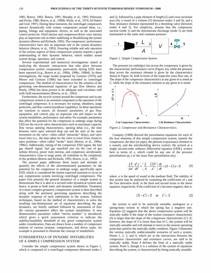
Consider the simple compression system shown in Figure 1,which is composed of a centrifugal compressor (between nodes 1
and 2), followed by a pipe element of length (L) and cross sectionalarea (A), a vessel of a volume (V) (between nodes 3 and 4), and aflow resistance element represented by a throttling valve (betweennodes 4 and 5). For simplicity, assume that the compressorsuction (node 1) and the downstream discharge (node 5) are bothmaintained at the same and constant pressure.
Figure 1. Simple Compression System.
The pressure (or enthalpy) rise across the compressor is given bythe characteristic performance curve (Figure 2a), while the pressuredrop across the resistance element is given by the characteristicsshown in Figure 2b, both in terms of the respective mass flow rate, mThe slope of the compressor characteristics at any given m is noted asC, while the slope of the resistance element at any given m is noted.
Figure 2. Compressor and Resistance Characteristics.
Cumpsty (1989) derived the perturbation equations for each ofthe four elements of this simple compression system, namely thecompressor, the duct (or pipe), the plenum (capacitance element ora vessel), and the end-throttling device (valve). He arrived at asingle second-order ordinary differential equation (ODE), writtenhere in terms of z, which could be any one of the pressureperturbations (pi ) or the mass flow perturbation (mi).
where, a is the speed of sound in the medium fluid. The stability ofthis system may be analyzed by examining the coefficients of z andthe first derivative dz/dt, in the third and second terms in the aboveequation, respectively. If the coefficient of z becomes negative, that is:
the system is said to be statically unstable, analogous to aspring-mass system in which the spring has a negative rate.Equation (2) suggests that the above compression system will bestatically stable if the slope of the system resistance characteristic(S) is larger than the slope of the compressor characteristic (C). If,however, the slope of S is lower than that of C, the system will bestatically unstable and will attempt to move to the nearest operatingpoint that satisfies the statically stable condition. Figure 3 illustratesthe various statically stable/unstable scenarios of such a system.Points 1, 2, 3, and 4, which are at the intersection between thecompressor characteristic and resistance curves, are said to bestatically stable. Point 4 defines the limit of a statically stablesystem. Point 5, though it is a solution of the system of equationsdescribing the system, is characterized by being statically unstable.
PROCEEDINGS OF THE THIRTY-SEVENTH TURBOMACHINERY SYMPOSIUM • 2008120
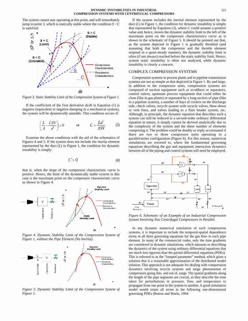
The system cannot stay operating at this point, and will immediatelyjump to point 3, which is statically stable where the condition S >Cis satisfied.
Figure 3. Static Stability Limit of the Compression System of Figure 1.
If the coefficient of the first derivative dz/dt in Equation (1) isnegative (equivalent to negative damping in a mechanical system),the system will be dynamically unstable. This condition occurs if:
Examine the above conditions with the aid of the schematics ofFigures 4 and 5. If the system does not include the inertia elementrepresented by the duct (L) in Figure 1, the condition for dynamicinstability is simply:
that is, when the slope of the compressor characteristic curve ispositive. Hence, the limit of the dynamically stable system in thiscase is the maximum point on the compressor characteristic curveas shown in Figure 4.
Figure 4. Dynamic Stability Limit of the Compression System ofFigure 1, without the Pipe Element (No Inertia).
Figure 5. Dynamic Stability Limit of the Compression System ofFigure 1.
If the system includes the inertial element represented by theduct (L) in Figure 1, the condition for dynamic instability is simplythat represented by Equation (3), where C could assume a positivevalue and, hence, moves the dynamic stability limit to the left of themaximum point on the compressor characteristics curve as isshown in the schematic of Figure 5. It should be pointed out that,as the system depicted in Figure 1 is gradually throttled (andassuming that both the compressor and the throttle elementrespond in a quasi-steady manner), the dynamic stability limit isoften (if not always) reached before the static stability limit. Hence,system static instability is often not analyzed, while dynamicinstability is clearly a concern.
COMPLEX COMPRESSION SYSTEMS
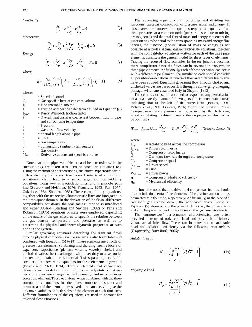
Compression systems in process plants and in pipeline transmissionsystems are not as simple as that depicted in Figure 1. By and large,in addition to the compressor units, compression systems arecomposed of suction equipment such as scrubbers or separators,control valves, upstream process equipment that could either beclose (like in gas plants) or separated by a long section of pipe (likein a pipeline system), a number of bays of coolers on the dischargeside, check valves, recycle system with recycle valves, blow-downor vent lines, and valves leading to a flare header system, etc.Although, in principle, the dynamic equation that describes such asystem can still be reduced to a second-order ordinary differentialequation in nature, it simply cannot be derived analytically due tothe complexity of the system and the sheer number of elementscomprising it. The problem could be doubly or triply accentuated ifthere are two or three compressor units operating in aparallel/series configuration (Figure 6). For this reason, numericalsimulations are resorted to, where the fundamental governingequations describing the gas and equipment interaction dynamicsbetween all of the piping and control systems still need be employed.
Figure 6. Schematic of an Example of an Industrial CompressionSystem Involving Two Centrifugal Compressors in Parallel.
In any dynamic numerical simulation of such compressionsystems, it is important to include the temporal-spatial dependenceterms in all three governing equations for the gas flow in each pipeelement. In many of the commercial codes, only the time gradientsare considered in dynamic simulations, which amounts to describingthe dynamics of the system using ordinary differential equations thatare much less rigorous than the partial differential equations (PDEs).This is referred to as the “lumped parameter” method, which gives asolution that is a reasonable approximation of the distributed modelsolution. This approach is not adequate for dealing with compressiondynamics involving recycle systems and surge phenomenon ofcompressors going into, and out of, surge. The spatial gradients alongthe length of the pipe segments are crucial, as they describe the timetaken for perturbations in pressure, flow, and temperature topropagate from one point in the system to another. A good simulationmodel would retain all terms in the following one-dimensionalgoverning PDEs (Botros and Petela, 1994:
121DYNAMIC INSTABILITIES IN INDUSTRIALCOMPRESSION SYSTEMSWITH CENTRIFUGAL COMPRESSORS
Continuity
Momentum
Energy
where
where:a = Speed of soundCv = Gas specific heat at constant volumeD = Pipe internal diameterE = Friction and heat transfer term defined in Equation (8)fDW = Darcy Weisbach friction factork = Overall heat transfer coefficient between fluid in pipe
and surrounding temperaturep = Pressurev = Gas mean flow velocityx = Spatial length along a pipet = TimeT = Gas temperatureTa = Surrounding (ambient) temperatureρ = Gas density( )v = Derivative at constant specific volume
Note that both pipe wall friction and heat transfer with thesurroundings are taken into account based on Equation (8).Using the method of characteristics, the above hyperbolic partialdifferential equations are transformed into total differentialequations, which lead to a set of algebraic compatibilityequations along two characteristic lines and a particle pathline (Zucrow and Hoffman, 1976; Kentfield, 1993; Fox, 1977;Osiadacz, 1984; Shapiro, 1983). These compatibility equations,together with the respective characteristic lines are integrated inthe time-space domain. In the derivation of the finite-differencecompatibility equations, the real gas assumption is introducedand either AGA-8 (Starling and Savidge, 1992) or Peng andRobinson (1976) equations of state were employed, dependingon the nature of the gas mixtures, to specify the relation betweenthe gas density, temperature, and pressure, as well as todetermine the physical and thermodynamic properties at eachnode in the system.
Similar governing equations describing the transient flowsthrough physical components in the system are also formulated andcombined with Equations (5) to (8). These elements are throttle orpressure loss elements, combining and dividing tees, reducers orexpanders, capacitance (plenum, volume, vessels), choked andunchoked valves, heat exchangers with a set duty or a set outlettemperature, adiabatic or isothermal flash separators, etc. A fullaccount of the governing equations for these elements is given in(Botros and Petela, 1994). Throttle elements and capacitanceelements are modeled based on quasi-steady-state equationsdescribing pressure changes as well as energy and mass balancesacross the element. These equations, when combined with the threecompatibility equations for the pipes connected upstream anddownstream of the element, are solved simultaneously to give theunknown variables on both sides of the element at each time step.Different formulations of the equations are used to account forreversed flow situations.
The governing equations for combining and dividing teejunctions represent conservation of pressure, mass, and energy. Inthese cases, the conservation equations require the equality of allthree pressures at a common node (pressure losses due to mixingare neglected) and the total flux of mass and energy that enters thejunction has to be equal to the corresponding mass and energy fluxleaving the junction (accumulation of mass or energy is notpossible at a node). Again, quasi-steady-state equations, togetherwith the compatibility equations written for each of the three pipeelements, constitute the general model for these types of elements.Tracing the reversed flow scenarios in the tee junction becomesmore complicated since the flows can be reversed in one, two, orthree pipe elements. Additionally, each of these scenarios can occurwith a different pipe element. The simulation code should considerall possible combinations of reversed flow and different treatmentshave been applied. Equations governing flow through choked andunchoked valves are based on flow through a converging-divergingpassage, which are described fully in Shapiro (1953).
The compressor itself is assumed to respond to any perturbationin a quasi-steady manner following its full characteristic curve,including that to the left of the surge limit (Botros, 1994;Botros, et al., 1991; Greitzer, 1976; Moore and Greitzer, 1986).Compressor/driver dynamics are governed by the followingequation; relating the driver power to the gas power and the inertiasof both units:
where:Ha = Adiabatic head across the compressorIdriver = Driver rotor inertiaIc = Compressor rotor inertiam = Gas mass flow rate through the compressorNc = Compressor speedNdriver = Driver speedt = TimeWdriver = Driver powerηa = Compressor adiabatic efficiencyηm = Mechanical efficiency
It should be noted that the driver and compressor inertias shouldalso include the inertia of the elements of the gearbox and couplingsconnected to either side, respectively. Additionally, in the case of atwo-shaft gas turbine driver, the applicable driver inertia inEquation (9) above is only the power turbine (i.e., the driver rotor)and coupling inertias, and not inclusive of the gas generator inertia.
The compressors’ performance characteristics are oftenprovided in terms of polytropic head and polytropic efficiencyversus actual inlet flow. These can be converted to adiabatichead and adiabatic efficiency via the following relationships(Engineering Data Book, 2006):
Adiabatic head
Polytropic head
PROCEEDINGS OF THE THIRTY-SEVENTH TURBOMACHINERY SYMPOSIUM • 2008122
Polytropic efficiency
Adiabatic efficiency
where:Ha = Adiabatic head across the compressorHp = Polytropic head across the compressork = Average isentropic exponent of the compressed gasn = Polytropic exponent of compressionPr = Pressure ratioR = Gas constantT1 = Upstream gas temperatureZav = Average compressibility factor across the compressorηa = Compressor adiabatic efficiencyηp = Compressor polytropic efficiency
In order to simulate the dynamic behavior of the compressor,including possibility of surging, the complete steady characteristicsof the unit beyond the surge point (i.e., left of the surge point)and into the negative flow is required. At a given flow to the leftof the surge limit, however, the actual head may differ from thesteady-state characteristics, which is the consequence of thecompressor going into surge. A physically realistic andcommonly used representation of this characteristic is that of asimple cubic given by the following equation (Greitzer, 1976;Moore and Greitzer, 1986):
where:Qa = Compressor actual inlet flowHa = Compressor adiabatic head at any given inlet flow (Qa)Ho = Compressor adiabatic head at zero flow =
0.5 (πN)2(Do2�Di
2)� = Parameter = 0.5 (Hs � Ho)Hs = Compressor head at surge point at the current
running speedQs = Compressor actual inlet flow at surge point at the
same speedDo = Impeller outer (tip) diameterDi = Impeller average inlet diameter
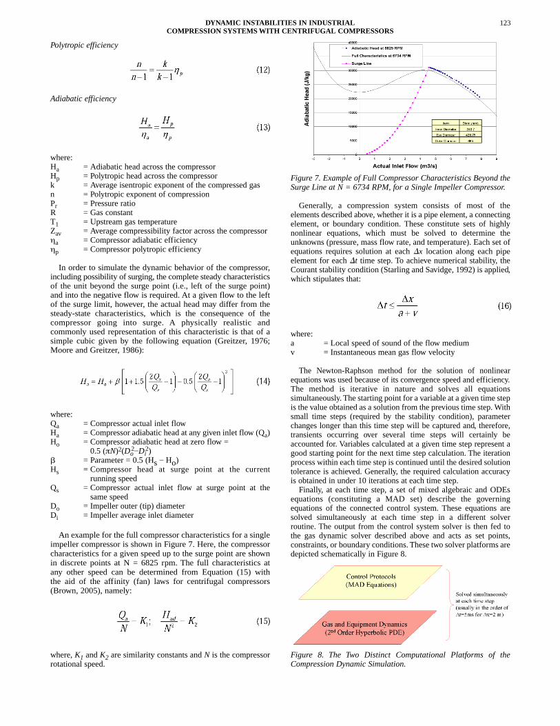
An example for the full compressor characteristics for a singleimpeller compressor is shown in Figure 7. Here, the compressorcharacteristics for a given speed up to the surge point are shownin discrete points at N = 6825 rpm. The full characteristics atany other speed can be determined from Equation (15) withthe aid of the affinity (fan) laws for centrifugal compressors(Brown, 2005), namely:
where, K1 and K2 are similarity constants and N is the compressorrotational speed.
Figure 7. Example of Full Compressor Characteristics Beyond theSurge Line at N = 6734 RPM, for a Single Impeller Compressor.
Generally, a compression system consists of most of theelements described above, whether it is a pipe element, a connectingelement, or boundary condition. These constitute sets of highlynonlinear equations, which must be solved to determine theunknowns (pressure, mass flow rate, and temperature). Each set ofequations requires solution at each �x location along each pipeelement for each �t time step. To achieve numerical stability, theCourant stability condition (Starling and Savidge, 1992) is applied,which stipulates that:
where:a = Local speed of sound of the flow mediumv = Instantaneous mean gas flow velocity
The Newton-Raphson method for the solution of nonlinearequations was used because of its convergence speed and efficiency.The method is iterative in nature and solves all equationssimultaneously. The starting point for a variable at a given time stepis the value obtained as a solution from the previous time step. Withsmall time steps (required by the stability condition), parameterchanges longer than this time step will be captured and, therefore,transients occurring over several time steps will certainly beaccounted for. Variables calculated at a given time step represent agood starting point for the next time step calculation. The iterationprocess within each time step is continued until the desired solutiontolerance is achieved. Generally, the required calculation accuracyis obtained in under 10 iterations at each time step.
Finally, at each time step, a set of mixed algebraic and ODEsequations (constituting a MAD set) describe the governingequations of the connected control system. These equations aresolved simultaneously at each time step in a different solverroutine. The output from the control system solver is then fed tothe gas dynamic solver described above and acts as set points,constraints, or boundary conditions. These two solver platforms aredepicted schematically in Figure 8.
Figure 8. The Two Distinct Computational Platforms of theCompression Dynamic Simulation.
DYNAMIC INSTABILITIES IN INDUSTRIALCOMPRESSION SYSTEMSWITH CENTRIFUGAL COMPRESSORS
123
DESCRIPTION OF THEEMERGENCY SHUTDOWNOPERATION OF A COMPRESSION SYSTEM
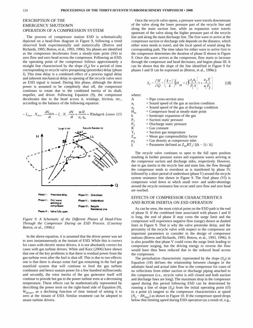
The process of compressor station ESD is schematicallydepicted on a head-flow diagram in Figure 9, following a trendobserved both experimentally and numerically (Botros andRichards, 1995; Botros, et al., 1993, 1996). Six phases are identifiedas the compressor decelerates from a steady-state point (SS) tozero flow and zero head across the compressor. Following an ESD,the operating point of the compressor follows approximately astraight line characterized by the slope (Sd) for a period of timecorresponding to recycle valve preopening (prestroke) delay (phaseI). This time delay is a combined effect of a process signal delayand inherent mechanical delay in opening of the recycle valve oncean ESD signal is issued. During this phase, although the driverpower is assumed to be completely shut off, the compressorcontinues to rotate due to the combined inertia of its shaft,impeller, and driver. Following Equation (9), the compressordecelerates due to the head across it, windage, friction, etc.,according to the balance of the following equation:
Figure 9. A Schematic of the Different Phases of Head-FlowThrough the Compressor During an ESD Process. (CourtesyBotros, et al., 1996c)
In the above equation, it is assumed that the driver power was setto zero instantaneously at the instant of ESD. While this is correctfor cases with electric motor drivers, it is not absolutely correct forcases with gas turbine drivers. White and Kurz (2006) have shownthat one of the key problems is that there is residual power from thegas turbine even after the fuel is shut off. This is due to two effects:one is that there is always some fuel gas remaining in the fuel gasmanifold system that will continue to feed the gas turbinecombustor and hence sustain power for a few hundred milliseconds;and secondly, the rotor inertia of the gas generator itself willcontinue to provide hot gas to the power turbine even at a decreasingtemperature. These effects can be mathematically represented bydescribing the power term on the right-hand side of Equation (9),Wdriver, as a declining function of time instead of setting it tozero at the instant of ESD. Similar treatment can be adopted tosteam turbine drivers.
Once the recycle valve opens, a pressure wave travels downstreamof the valve along the lower pressure part of the recycle line andalong the main suction line, while an expansion wave travelsupstream of the valve along the higher pressure part of the recycleline and along the main discharge line. The first wave to arrive at thecompressor suction or discharge side depends on the distance, whicheither wave needs to travel, and the local speed of sound along thecorresponding path. The time taken for either wave to arrive first tothe compressor determines the duration of phase II shown in Figure9. Once this wave arrives at the compressor, flow starts to increasethrough the compressor and head decreases, and begins phase III. Itcan be shown that the slope of the line identified in Figure 9 forphases I and II can be expressed as (Botros, et al., 1996c):
where:A = Pipe cross-section areaa1 = Sound speed of the gas at suction conditiona2 = Sound speed of the gas at discharge conditionHss = Compressor head at steady-state pointk = Isentropic expansion of the gasP1 = Suction static pressureP2 = Discharge static pressureR = Gas constantT1 = Suction gas temperatureZav = Mean gas compressibility factor�1 = Gas density at compressor inlet� = Parameter defined as ZavRT1/ [(k � 1) / k]
The recycle valve continues to open to the full open positionresulting in further pressure waves and expansion waves arriving atthe compressor suction and discharge sides, respectively. However,due to gas inertia in the recycle line and main line, the flow throughthe compressor tends to overshoot as is manifested by phase IV,followed by a short period of undershoot (phase V) around the recyclesystem resistance line shown in Figure 9. The final phase (VI) iscompressor wind down in which small over- and under-shootingsaround the recycle resistance line occur until zero flow and zero headare reached.
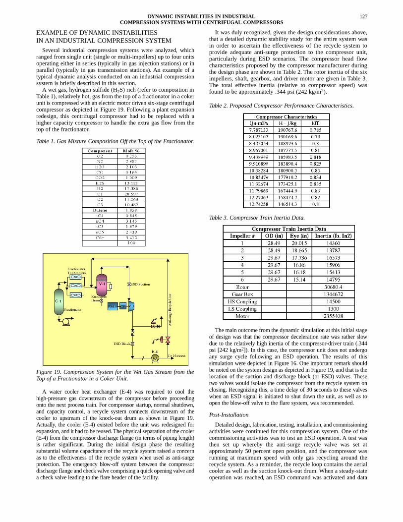
EFFECTS OF COMPRESSOR CHARACTERISTICSAND ROTOR INERTIA ON ESD OPERATION
As can be seen, the most critical point on the ESD path is the endof phase II. If the combined time associated with phases I and IIis long, the end of phase II may cross the surge limit and thecompressor will experience negative flow (surge) shown as dashedlines in Figure 9. That is why the valve prestroke delay, and theproximity of the recycle valve with respect to the compressor areimportant parameters to consider in the design of compressorstations (Botros and Richards, 1995; Botros, et al., 1993, 1996). Itis also possible that phase V could cross the surge limit leading tocompressor surging, but the driving energy to reverse the flowwould have then been reduced due to the reduced head acrossthe compressor.
The perturbation characteristic represented by the slope (Sd) inEquation (18) defines the relationship between changes in theadiabatic head and actual inlet flow to the compressor for cases ofno reflections from either suction or discharge piping attached tothe compressor (i.e., recycle valve is still closed and both suctionand discharge lines are long). The maximum drop in the compressorspeed during this period following ESD can be determined byrunning a line of slope (Sd) from the initial operating point (O)to a point (t) tangent to the compressor characteristics at speed(No � �Nmax) as shown in Figure 10. If the compressor speed dropsbelow that limiting speed during ESD operation (as a result of, e.g.,
PROCEEDINGS OF THE THIRTY-SEVENTH TURBOMACHINERY SYMPOSIUM • 2008124
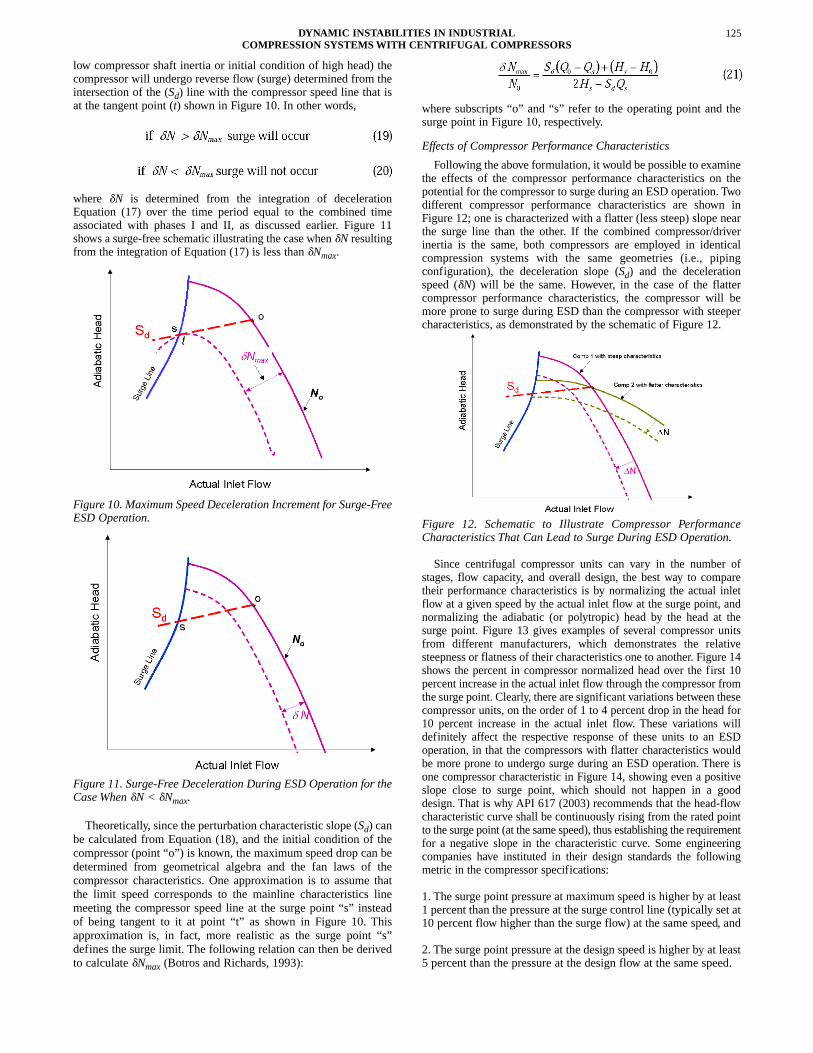
low compressor shaft inertia or initial condition of high head) thecompressor will undergo reverse flow (surge) determined from theintersection of the (Sd) line with the compressor speed line that isat the tangent point (t) shown in Figure 10. In other words,
where �N is determined from the integration of decelerationEquation (17) over the time period equal to the combined timeassociated with phases I and II, as discussed earlier. Figure 11shows a surge-free schematic illustrating the case when �N resultingfrom the integration of Equation (17) is less than �Nmax.
Figure 10. Maximum Speed Deceleration Increment for Surge-FreeESD Operation.
Figure 11. Surge-Free Deceleration During ESD Operation for theCase When �N < �Nmax.
Theoretically, since the perturbation characteristic slope (Sd) canbe calculated from Equation (18), and the initial condition of thecompressor (point “o”) is known, the maximum speed drop can bedetermined from geometrical algebra and the fan laws of thecompressor characteristics. One approximation is to assume thatthe limit speed corresponds to the mainline characteristics linemeeting the compressor speed line at the surge point “s” insteadof being tangent to it at point “t” as shown in Figure 10. Thisapproximation is, in fact, more realistic as the surge point “s”defines the surge limit. The following relation can then be derivedto calculate �Nmax (Botros and Richards, 1993):
where subscripts “o” and “s” refer to the operating point and thesurge point in Figure 10, respectively.
Effects of Compressor Performance Characteristics
Following the above formulation, it would be possible to examinethe effects of the compressor performance characteristics on thepotential for the compressor to surge during an ESD operation. Twodifferent compressor performance characteristics are shown inFigure 12; one is characterized with a flatter (less steep) slope nearthe surge line than the other. If the combined compressor/driverinertia is the same, both compressors are employed in identicalcompression systems with the same geometries (i.e., pipingconfiguration), the deceleration slope (Sd) and the decelerationspeed (�N) will be the same. However, in the case of the flattercompressor performance characteristics, the compressor will bemore prone to surge during ESD than the compressor with steepercharacteristics, as demonstrated by the schematic of Figure 12.
Figure 12. Schematic to Illustrate Compressor PerformanceCharacteristics That Can Lead to Surge During ESD Operation.
Since centrifugal compressor units can vary in the number ofstages, flow capacity, and overall design, the best way to comparetheir performance characteristics is by normalizing the actual inletflow at a given speed by the actual inlet flow at the surge point, andnormalizing the adiabatic (or polytropic) head by the head at thesurge point. Figure 13 gives examples of several compressor unitsfrom different manufacturers, which demonstrates the relativesteepness or flatness of their characteristics one to another. Figure 14shows the percent in compressor normalized head over the first 10percent increase in the actual inlet flow through the compressor fromthe surge point. Clearly, there are significant variations between thesecompressor units, on the order of 1 to 4 percent drop in the head for10 percent increase in the actual inlet flow. These variations willdefinitely affect the respective response of these units to an ESDoperation, in that the compressors with flatter characteristics wouldbe more prone to undergo surge during an ESD operation. There isone compressor characteristic in Figure 14, showing even a positiveslope close to surge point, which should not happen in a gooddesign. That is why API 617 (2003) recommends that the head-flowcharacteristic curve shall be continuously rising from the rated pointto the surge point (at the same speed), thus establishing the requirementfor a negative slope in the characteristic curve. Some engineeringcompanies have instituted in their design standards the followingmetric in the compressor specifications:
1. The surge point pressure at maximum speed is higher by at least1 percent than the pressure at the surge control line (typically set at10 percent flow higher than the surge flow) at the same speed, and
2. The surge point pressure at the design speed is higher by at least5 percent than the pressure at the design flow at the same speed.
125DYNAMIC INSTABILITIES IN INDUSTRIALCOMPRESSION SYSTEMSWITH CENTRIFUGAL COMPRESSORS
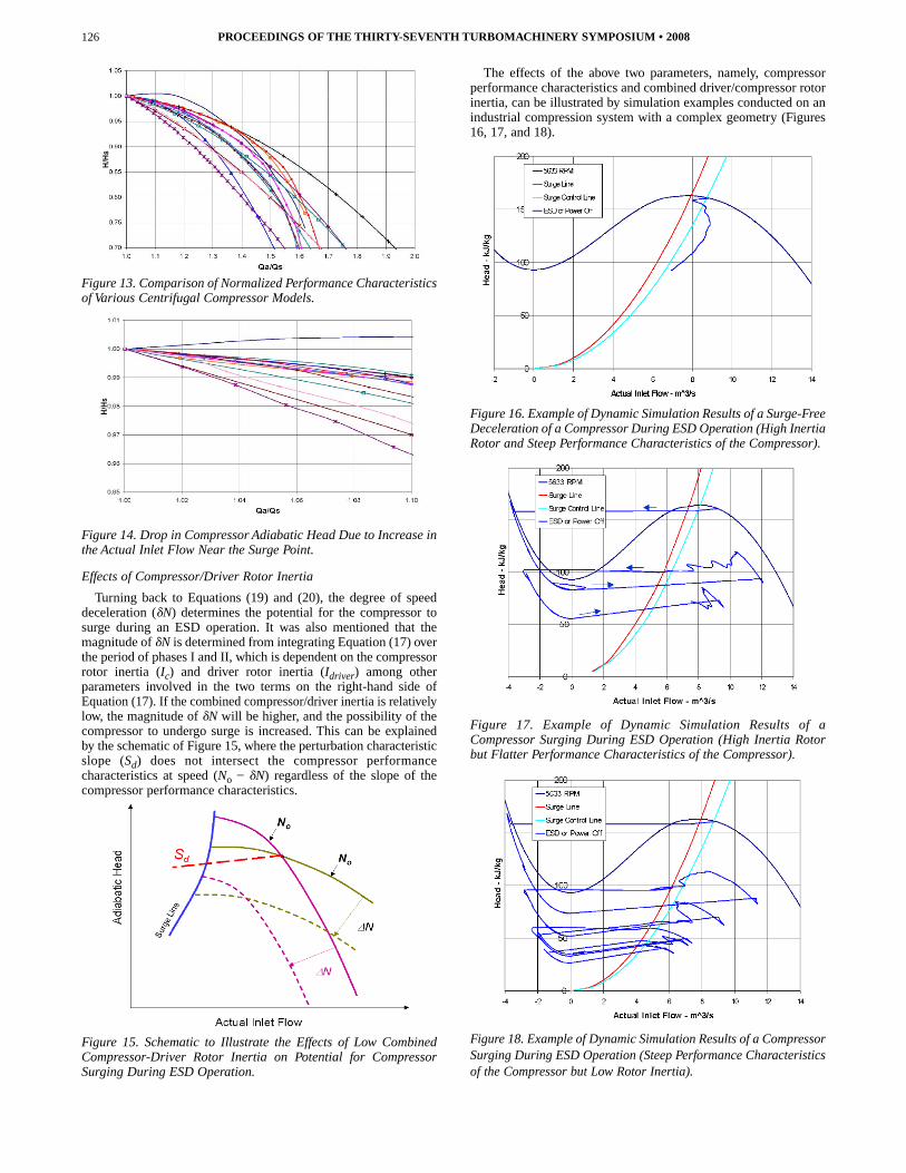
Figure 13. Comparison of Normalized Performance Characteristicsof Various Centrifugal Compressor Models.
Figure 14. Drop in Compressor Adiabatic Head Due to Increase inthe Actual Inlet Flow Near the Surge Point.
Effects of Compressor/Driver Rotor Inertia
Turning back to Equations (19) and (20), the degree of speeddeceleration (�N) determines the potential for the compressor tosurge during an ESD operation. It was also mentioned that themagnitude of �N is determined from integrating Equation (17) overthe period of phases I and II, which is dependent on the compressorrotor inertia (Ic) and driver rotor inertia (Idriver) among otherparameters involved in the two terms on the right-hand side ofEquation (17). If the combined compressor/driver inertia is relativelylow, the magnitude of �N will be higher, and the possibility of thecompressor to undergo surge is increased. This can be explainedby the schematic of Figure 15, where the perturbation characteristicslope (Sd) does not intersect the compressor performancecharacteristics at speed (No � �N) regardless of the slope of thecompressor performance characteristics.
Figure 15. Schematic to Illustrate the Effects of Low CombinedCompressor-Driver Rotor Inertia on Potential for CompressorSurging During ESD Operation.
The effects of the above two parameters, namely, compressorperformance characteristics and combined driver/compressor rotorinertia, can be illustrated by simulation examples conducted on anindustrial compression system with a complex geometry (Figures16, 17, and 18).
Figure 16. Example of Dynamic Simulation Results of a Surge-FreeDeceleration of a Compressor During ESD Operation (High InertiaRotor and Steep Performance Characteristics of the Compressor).
Figure 17. Example of Dynamic Simulation Results of aCompressor Surging During ESD Operation (High Inertia Rotorbut Flatter Performance Characteristics of the Compressor).
Figure 18. Example of Dynamic Simulation Results of a CompressorSurging During ESD Operation (Steep Performance Characteristicsof the Compressor but Low Rotor Inertia).
PROCEEDINGS OF THE THIRTY-SEVENTH TURBOMACHINERY SYMPOSIUM • 2008126
EXAMPLE OF DYNAMIC INSTABILITIESIN AN INDUSTRIAL COMPRESSION SYSTEM
Several industrial compression systems were analyzed, whichranged from single unit (single or multi-impellers) up to four unitsoperating either in series (typically in gas injection stations) or inparallel (typically in gas transmission stations). An example of atypical dynamic analysis conducted on an industrial compressionsystem is briefly described in this section.
A wet gas, hydrogen sulfide (H2S) rich (refer to composition inTable 1), relatively hot, gas from the top of a fractionator in a cokerunit is compressed with an electric motor driven six-stage centrifugalcompressor as depicted in Figure 19. Following a plant expansionredesign, this centrifugal compressor had to be replaced with ahigher capacity compressor to handle the extra gas flow from thetop of the fractionator.
Table 1. Gas Mixture Composition Off the Top of the Fractionator.
Figure 19. Compression System for the Wet Gas Stream from theTop of a Fractionator in a Coker Unit.
A water cooler heat exchanger (E-4) was required to cool thehigh-pressure gas downstream of the compressor before proceedingonto the next process train. For compressor startup, normal shutdown,and capacity control, a recycle system connects downstream of thecooler to upstream of the knock-out drum as shown in Figure 19.Actually, the cooler (E-4) existed before the unit was redesigned forexpansion, and it had to be reused. The physical separation of the cooler(E-4) from the compressor discharge flange (in terms of piping length)is rather significant. During the initial design phase the resultingsubstantial volume capacitance of the recycle system raised a concernas to the effectiveness of the recycle system when used as anti-surgeprotection. The emergency blow-off system between the compressordischarge flange and check valve comprising a quick opening valve anda check valve leading to the flare header of the facility.
It was duly recognized, given the design considerations above,that a detailed dynamic stability study for the entire system wasin order to ascertain the effectiveness of the recycle system toprovide adequate anti-surge protection to the compressor unit,particularly during ESD scenarios. The compressor head flowcharacteristics proposed by the compressor manufacturer duringthe design phase are shown in Table 2. The rotor inertia of the siximpellers, shaft, gearbox, and driver motor are given in Table 3.The total effective inertia (relative to compressor speed) wasfound to be approximately .344 psi (242 kg/m2).
Table 2. Proposed Compressor Performance Characteristics.
Table 3. Compressor Train Inertia Data.
The main outcome from the dynamic simulation at this initial stageof design was that the compressor deceleration rate was rather slowdue to the relatively high inertia of the compressor-driver train (.344psi [242 kg/m2]). In this case, the compressor unit does not undergoany surge cycle following an ESD operation. The results of thissimulation were depicted in Figure 16. One important remark shouldbe noted on the system design as depicted in Figure 19, and that is thelocation of the suction and discharge block (or ESD) valves. Thesetwo valves would isolate the compressor from the recycle system onclosing. Recognizing this, a time delay of 30 seconds to these valveswhen an ESD signal is initiated to shut down the unit, as well as toopen the blow-off valve to the flare system, was recommended.
Post-Installation
Detailed design, fabrication, testing, installation, and commissioningactivities were continued for this compression system. One of thecommissioning activities was to test an ESD operation. A test wasthen set up whereby the anti-surge recycle valve was set atapproximately 50 percent open position, and the compressor wasrunning at maximum speed with only gas recycling around therecycle system. As a reminder, the recycle loop contains the aerialcooler as well as the suction knock-out drum. When a steady-stateoperation was reached, an ESD command was activated and data
DYNAMIC INSTABILITIES IN INDUSTRIALCOMPRESSION SYSTEMSWITH CENTRIFUGAL COMPRESSORS
127
were collected with a sampling frequency of 1 Hz (i.e., 1 secondintervals). These data (Figure 20) show that the compressor hasactually gone one surge cycle during the speed coastdownfollowing ESD. In this installation, compressor flow is measuredby an orifice plate located at the discharge side of the compressorunit. Therefore, the reversed flow through the compressor duringthis surge cycle was registered as zero flow because the differentialpressure across the orifice plate was not set up to measure negativedifferential pressure (DP). This test was repeated but with thevariable frequency drive (VFD) of the motor initiating the ESD.Again the same trend occurred and the event confirmed theoccurrence of one surge cycle during the coastdown following ESD.
Figure 20. Field Measurement Showing Compressor SurgingFollowing ESD.
Reevaluation of “As-Built” Condition
The above problem triggered another reevaluation of thecompression system dynamics study. In this case, all of the pertinentparameters that were used in the initial dynamic simulation werereconfirmed. During this process, three major differences in the dataused were discovered. Those were:
• The as-built compressor train inertia data were provided by themanufacturer, which revealed that the actual with total effectiveinertia (with respect to the compressor side) was .146 psi (102.5kg/m2), instead of the .344 psi (242 kg/m2) previously used duringthe design phase.
• Secondly, the shop-tested compressor performance characteristicsshowed a much flatter characteristic, especially at flows closeto the surge limit. Figure 21 shows comparison between theshop-tested compressor characteristic vs. the initially proposedcharacteristic. In fact, the shop-tested performance curve exhibitsa positive slope close to the surge point as shown in Figure 22.
Figure 21. Shop-Tested Versus Proposed Compressor Characteristicsat the Same Speed (6034 RPM).
Figure 22. Normalized Flow Versus Compressor Curve Slope forBoth Proposed and Tested Curves.
• Thirdly, the prestroke delay as well as the actual travel time tofull stroke of the blow-off valve to the flare system were found tobe approximately 330 milliseconds and 1.667 seconds, respectively.These values were recognized to be much too slow, and that thepressure relief that should be provided by the blow-off valve toprotect the unit from surge would come after the compressor wouldhave gone through the first surge cycle. Figure 23 shows theprocess parameters (suction, discharge pressures, and compressorflow) starting from the time when the ESD signal was initiated.Clearly, a combined 2 second delay until the blow-off valve is fullyopen comes too late, during which the compressor has alreadyundergone one complete surge cycle.
Figure 23. Process Parameters During Compressor SurgeFollowing ESD.
Dynamic simulations of several ESD scenarios were thenconducted using these new data, particularly since the compressorshop-tested performance characteristics showed much flattercharacteristics, which raised considerable concerns. The firstsuggested solution scenario was to increase the size of the blow-offvalve from an 8 inch to a 12 inch valve with a quick-open trim withCv = 1210, prestroke time of 100 milliseconds, and stroke time of 1.0second. Dynamic simulation showed that with this scenario, thecompressor would be protected from surging during ESD. However,this option required considerable shutdown time and significantlylonger lead-time to procure the specified 12 inch valve. (Note:opening the existing blow-off valve to flare 1 or 2 seconds beforeinitiating the ESD signal was also considered and discarded since inthe event of power failure or VFD failure, it is impossible to imposethis delay on the power to an electric motor). In the end, all changesand modifications to the blow-off to flare valve to protect the unitfrom surging were not possible. The only viable option was to installa short (hot) recycle system around the compressor unit, utilizing theexisting check valve at the blow-off point.
A short recycle system was then sized, and dynamic simulations ofthe ESD indicated that a 12 inch globe valve with a quick-opentrim and Cv = 1600 would be adequate. However, due to the flatcompressor performance characteristics, operation of the compressorhad to be limited to flow rates higher than those specified by the
PROCEEDINGS OF THE THIRTY-SEVENTH TURBOMACHINERY SYMPOSIUM • 2008128
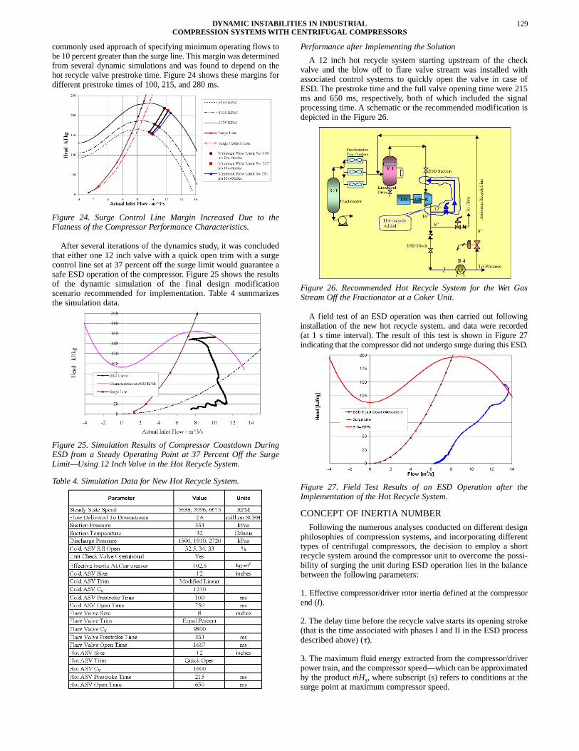
commonly used approach of specifying minimum operating flows tobe 10 percent greater than the surge line. This margin was determinedfrom several dynamic simulations and was found to depend on thehot recycle valve prestroke time. Figure 24 shows these margins fordifferent prestroke times of 100, 215, and 280 ms.
Figure 24. Surge Control Line Margin Increased Due to theFlatness of the Compressor Performance Characteristics.
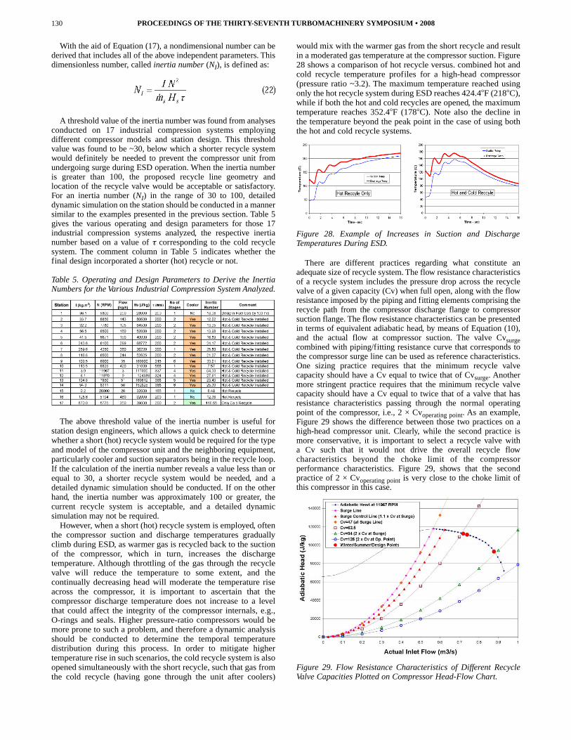
After several iterations of the dynamics study, it was concludedthat either one 12 inch valve with a quick open trim with a surgecontrol line set at 37 percent off the surge limit would guarantee asafe ESD operation of the compressor. Figure 25 shows the resultsof the dynamic simulation of the final design modificationscenario recommended for implementation. Table 4 summarizesthe simulation data.
Figure 25. Simulation Results of Compressor Coastdown DuringESD from a Steady Operating Point at 37 Percent Off the SurgeLimit—Using 12 Inch Valve in the Hot Recycle System.
Table 4. Simulation Data for New Hot Recycle System.
Performance after Implementing the Solution
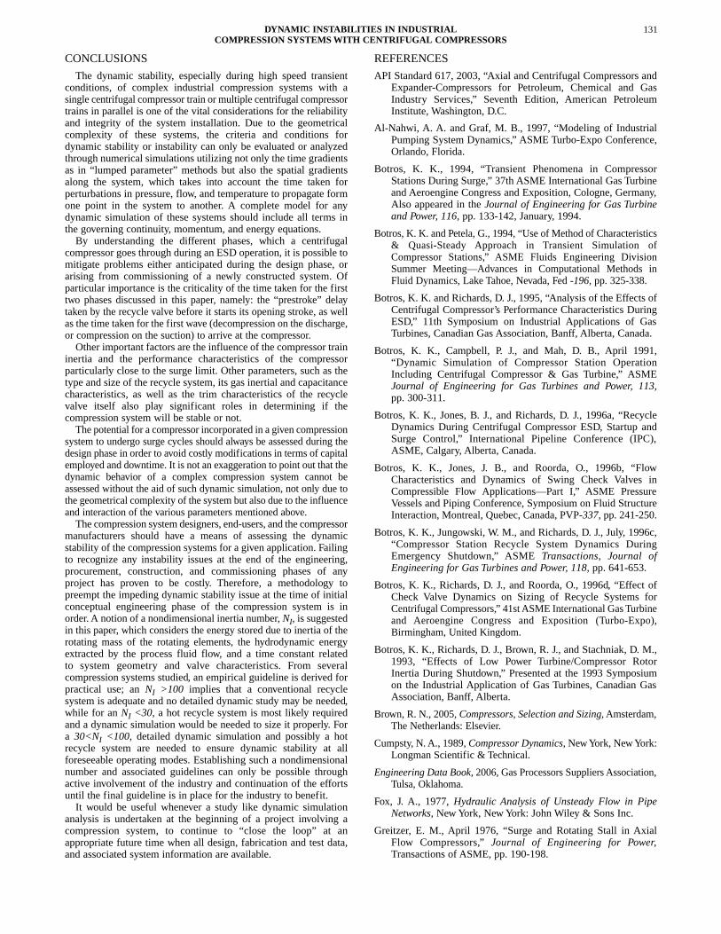
A 12 inch hot recycle system starting upstream of the checkvalve and the blow off to flare valve stream was installed withassociated control systems to quickly open the valve in case ofESD. The prestroke time and the full valve opening time were 215ms and 650 ms, respectively, both of which included the signalprocessing time. A schematic or the recommended modification isdepicted in the Figure 26.
Figure 26. Recommended Hot Recycle System for the Wet GasStream Off the Fractionator at a Coker Unit.
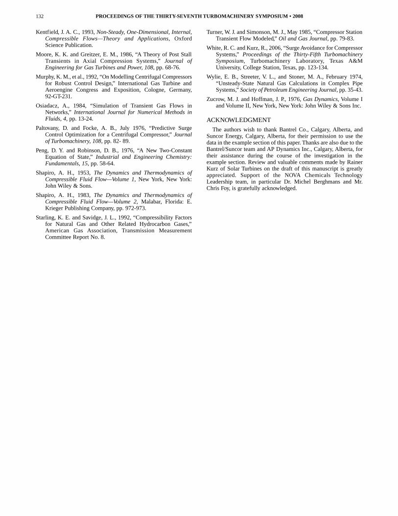
A field test of an ESD operation was then carried out followinginstallation of the new hot recycle system, and data were recorded(at 1 s time interval). The result of this test is shown in Figure 27indicating that the compressor did not undergo surge during this ESD.
Figure 27. Field Test Results of an ESD Operation after theImplementation of the Hot Recycle System.
CONCEPT OF INERTIA NUMBER
Following the numerous analyses conducted on different designphilosophies of compression systems, and incorporating differenttypes of centrifugal compressors, the decision to employ a shortrecycle system around the compressor unit to overcome the possi-bility of surging the unit during ESD operation lies in the balancebetween the following parameters:
1. Effective compressor/driver rotor inertia defined at the compressorend (I).
2. The delay time before the recycle valve starts its opening stroke(that is the time associated with phases I and II in the ESD processdescribed above) (τ).
3. The maximum fluid energy extracted from the compressor/driverpower train, and the compressor speed—which can be approximatedby the product mHs, where subscript (s) refers to conditions at thesurge point at maximum compressor speed.
DYNAMIC INSTABILITIES IN INDUSTRIALCOMPRESSION SYSTEMSWITH CENTRIFUGAL COMPRESSORS
129
With the aid of Equation (17), a nondimensional number can bederived that includes all of the above independent parameters. Thisdimensionless number, called inertia number (NI), is defined as:
A threshold value of the inertia number was found from analysesconducted on 17 industrial compression systems employingdifferent compressor models and station design. This thresholdvalue was found to be ~30, below which a shorter recycle systemwould definitely be needed to prevent the compressor unit fromundergoing surge during ESD operation. When the inertia numberis greater than 100, the proposed recycle line geometry andlocation of the recycle valve would be acceptable or satisfactory.For an inertia number (NI) in the range of 30 to 100, detaileddynamic simulation on the station should be conducted in a mannersimilar to the examples presented in the previous section. Table 5gives the various operating and design parameters for those 17industrial compression systems analyzed, the respective inertianumber based on a value of τ corresponding to the cold recyclesystem. The comment column in Table 5 indicates whether thefinal design incorporated a shorter (hot) recycle or not.
Table 5. Operating and Design Parameters to Derive the InertiaNumbers for the Various Industrial Compression System Analyzed.
The above threshold value of the inertia number is useful forstation design engineers, which allows a quick check to determinewhether a short (hot) recycle system would be required for the typeand model of the compressor unit and the neighboring equipment,particularly cooler and suction separators being in the recycle loop.If the calculation of the inertia number reveals a value less than orequal to 30, a shorter recycle system would be needed, and adetailed dynamic simulation should be conducted. If on the otherhand, the inertia number was approximately 100 or greater, thecurrent recycle system is acceptable, and a detailed dynamicsimulation may not be required.
However, when a short (hot) recycle system is employed, oftenthe compressor suction and discharge temperatures graduallyclimb during ESD, as warmer gas is recycled back to the suctionof the compressor, which in turn, increases the dischargetemperature. Although throttling of the gas through the recyclevalve will reduce the temperature to some extent, and thecontinually decreasing head will moderate the temperature riseacross the compressor, it is important to ascertain that thecompressor discharge temperature does not increase to a levelthat could affect the integrity of the compressor internals, e.g.,O-rings and seals. Higher pressure-ratio compressors would bemore prone to such a problem, and therefore a dynamic analysisshould be conducted to determine the temporal temperaturedistribution during this process. In order to mitigate highertemperature rise in such scenarios, the cold recycle system is alsoopened simultaneously with the short recycle, such that gas fromthe cold recycle (having gone through the unit after coolers)
would mix with the warmer gas from the short recycle and resultin a moderated gas temperature at the compressor suction. Figure28 shows a comparison of hot recycle versus. combined hot andcold recycle temperature profiles for a high-head compressor(pressure ratio ~3.2). The maximum temperature reached usingonly the hot recycle system during ESD reaches 424.4�F (218�C),while if both the hot and cold recycles are opened, the maximumtemperature reaches 352.4�F (178�C). Note also the decline inthe temperature beyond the peak point in the case of using boththe hot and cold recycle systems.
Figure 28. Example of Increases in Suction and DischargeTemperatures During ESD.
There are different practices regarding what constitute anadequate size of recycle system. The flow resistance characteristicsof a recycle system includes the pressure drop across the recyclevalve of a given capacity (Cv) when full open, along with the flowresistance imposed by the piping and fitting elements comprising therecycle path from the compressor discharge flange to compressorsuction flange. The flow resistance characteristics can be presentedin terms of equivalent adiabatic head, by means of Equation (10),and the actual flow at compressor suction. The valve Cvsurgecombined with piping/fitting resistance curve that corresponds tothe compressor surge line can be used as reference characteristics.One sizing practice requires that the minimum recycle valvecapacity should have a Cv equal to twice that of Cvsurge. Anothermore stringent practice requires that the minimum recycle valvecapacity should have a Cv equal to twice that of a valve that hasresistance characteristics passing through the normal operatingpoint of the compressor, i.e., 2 × Cvoperating point. As an example,Figure 29 shows the difference between those two practices on ahigh-head compressor unit. Clearly, while the second practice ismore conservative, it is important to select a recycle valve witha Cv such that it would not drive the overall recycle flowcharacteristics beyond the choke limit of the compressorperformance characteristics. Figure 29, shows that the secondpractice of 2 × Cvoperating point is very close to the choke limit ofthis compressor in this case.
Figure 29. Flow Resistance Characteristics of Different RecycleValve Capacities Plotted on Compressor Head-Flow Chart.
PROCEEDINGS OF THE THIRTY-SEVENTH TURBOMACHINERY SYMPOSIUM • 2008130
CONCLUSIONS
The dynamic stability, especially during high speed transientconditions, of complex industrial compression systems with asingle centrifugal compressor train or multiple centrifugal compressortrains in parallel is one of the vital considerations for the reliabilityand integrity of the system installation. Due to the geometricalcomplexity of these systems, the criteria and conditions fordynamic stability or instability can only be evaluated or analyzedthrough numerical simulations utilizing not only the time gradientsas in “lumped parameter” methods but also the spatial gradientsalong the system, which takes into account the time taken forperturbations in pressure, flow, and temperature to propagate formone point in the system to another. A complete model for anydynamic simulation of these systems should include all terms inthe governing continuity, momentum, and energy equations.
By understanding the different phases, which a centrifugalcompressor goes through during an ESD operation, it is possible tomitigate problems either anticipated during the design phase, orarising from commissioning of a newly constructed system. Ofparticular importance is the criticality of the time taken for the firsttwo phases discussed in this paper, namely: the “prestroke” delaytaken by the recycle valve before it starts its opening stroke, as wellas the time taken for the first wave (decompression on the discharge,or compression on the suction) to arrive at the compressor.
Other important factors are the influence of the compressor traininertia and the performance characteristics of the compressorparticularly close to the surge limit. Other parameters, such as thetype and size of the recycle system, its gas inertial and capacitancecharacteristics, as well as the trim characteristics of the recyclevalve itself also play significant roles in determining if thecompression system will be stable or not.
The potential for a compressor incorporated in a given compressionsystem to undergo surge cycles should always be assessed during thedesign phase in order to avoid costly modifications in terms of capitalemployed and downtime. It is not an exaggeration to point out that thedynamic behavior of a complex compression system cannot beassessed without the aid of such dynamic simulation, not only due tothe geometrical complexity of the system but also due to the influenceand interaction of the various parameters mentioned above.
The compression system designers, end-users, and the compressormanufacturers should have a means of assessing the dynamicstability of the compression systems for a given application. Failingto recognize any instability issues at the end of the engineering,procurement, construction, and commissioning phases of anyproject has proven to be costly. Therefore, a methodology topreempt the impeding dynamic stability issue at the time of initialconceptual engineering phase of the compression system is inorder. A notion of a nondimensional inertia number, NI, is suggestedin this paper, which considers the energy stored due to inertia of therotating mass of the rotating elements, the hydrodynamic energyextracted by the process fluid flow, and a time constant relatedto system geometry and valve characteristics. From severalcompression systems studied, an empirical guideline is derived forpractical use; an NI >100 implies that a conventional recyclesystem is adequate and no detailed dynamic study may be needed,while for an NI <30, a hot recycle system is most likely requiredand a dynamic simulation would be needed to size it properly. Fora 30<NI <100, detailed dynamic simulation and possibly a hotrecycle system are needed to ensure dynamic stability at allforeseeable operating modes. Establishing such a nondimensionalnumber and associated guidelines can only be possible throughactive involvement of the industry and continuation of the effortsuntil the final guideline is in place for the industry to benefit.
It would be useful whenever a study like dynamic simulationanalysis is undertaken at the beginning of a project involving acompression system, to continue to “close the loop” at anappropriate future time when all design, fabrication and test data,and associated system information are available.
REFERENCES
API Standard 617, 2003, “Axial and Centrifugal Compressors andExpander-Compressors for Petroleum, Chemical and GasIndustry Services,” Seventh Edition, American PetroleumInstitute, Washington, D.C.
Al-Nahwi, A. A. and Graf, M. B., 1997, “Modeling of IndustrialPumping System Dynamics,” ASME Turbo-Expo Conference,Orlando, Florida.
Botros, K. K., 1994, “Transient Phenomena in CompressorStations During Surge,” 37th ASME International Gas Turbineand Aeroengine Congress and Exposition, Cologne, Germany,Also appeared in the Journal of Engineering for Gas Turbineand Power, 116, pp. 133-142, January, 1994.
Botros, K. K. and Petela, G., 1994, “Use of Method of Characteristics& Quasi-Steady Approach in Transient Simulation ofCompressor Stations,” ASME Fluids Engineering DivisionSummer Meeting—Advances in Computational Methods inFluid Dynamics, Lake Tahoe, Nevada, Fed -196, pp. 325-338.
Botros, K. K. and Richards, D. J., 1995, “Analysis of the Effects ofCentrifugal Compressor’s Performance Characteristics DuringESD,” 11th Symposium on Industrial Applications of GasTurbines, Canadian Gas Association, Banff, Alberta, Canada.
Botros, K. K., Campbell, P. J., and Mah, D. B., April 1991,“Dynamic Simulation of Compressor Station OperationIncluding Centrifugal Compressor & Gas Turbine,” ASMEJournal of Engineering for Gas Turbines and Power, 113,pp. 300-311.
Botros, K. K., Jones, B. J., and Richards, D. J., 1996a, “RecycleDynamics During Centrifugal Compressor ESD, Startup andSurge Control,” International Pipeline Conference (IPC),ASME, Calgary, Alberta, Canada.
Botros, K. K., Jones, J. B., and Roorda, O., 1996b, “FlowCharacteristics and Dynamics of Swing Check Valves inCompressible Flow Applications—Part I,” ASME PressureVessels and Piping Conference, Symposium on Fluid StructureInteraction, Montreal, Quebec, Canada, PVP-337, pp. 241-250.
Botros, K. K., Jungowski, W. M., and Richards, D. J., July, 1996c,“Compressor Station Recycle System Dynamics DuringEmergency Shutdown,” ASME Transactions, Journal ofEngineering for Gas Turbines and Power, 118, pp. 641-653.
Botros, K. K., Richards, D. J., and Roorda, O., 1996d, “Effect ofCheck Valve Dynamics on Sizing of Recycle Systems forCentrifugal Compressors,” 41st ASME International Gas Turbineand Aeroengine Congress and Exposition (Turbo-Expo),Birmingham, United Kingdom.
Botros, K. K., Richards, D. J., Brown, R. J., and Stachniak, D. M.,1993, “Effects of Low Power Turbine/Compressor RotorInertia During Shutdown,” Presented at the 1993 Symposiumon the Industrial Application of Gas Turbines, Canadian GasAssociation, Banff, Alberta.
Brown, R. N., 2005, Compressors, Selection and Sizing,Amsterdam,The Netherlands: Elsevier.
Cumpsty, N. A., 1989, Compressor Dynamics, NewYork, NewYork:Longman Scientific & Technical.
Engineering Data Book, 2006, Gas Processors Suppliers Association,Tulsa, Oklahoma.
Fox, J. A., 1977, Hydraulic Analysis of Unsteady Flow in PipeNetworks, NewYork, NewYork: John Wiley & Sons Inc.
Greitzer, E. M., April 1976, “Surge and Rotating Stall in AxialFlow Compressors,” Journal of Engineering for Power,Transactions of ASME, pp. 190-198.
DYNAMIC INSTABILITIES IN INDUSTRIALCOMPRESSION SYSTEMSWITH CENTRIFUGAL COMPRESSORS
131
Kentfield, J. A. C., 1993, Non-Steady, One-Dimensional, Internal,Compressible Flows—Theory and Applications, OxfordScience Publication.
Moore, K. K. and Greitzer, E. M., 1986, “A Theory of Post StallTransients in Axial Compression Systems,” Journal ofEngineering for Gas Turbines and Power, 108, pp. 68-76.
Murphy, K. M., et al., 1992, “On Modelling Centrifugal Compressorsfor Robust Control Design,” International Gas Turbine andAeroengine Congress and Exposition, Cologne, Germany,92-GT-231.
Osiadacz, A., 1984, “Simulation of Transient Gas Flows inNetworks,” International Journal for Numerical Methods inFluids, 4, pp. 13-24.
Paltovany, D. and Focke, A. B., July 1976, “Predictive SurgeControl Optimization for a Centrifugal Compressor,” Journalof Turbomachinery, 108, pp. 82- 89.
Peng, D. Y. and Robinson, D. B., 1976, “A New Two-ConstantEquation of State,” Industrial and Engineering Chemistry:Fundamentals, 15, pp. 58-64.
Shapiro, A. H., 1953, The Dynamics and Thermodynamics ofCompressible Fluid Flow—Volume 1, New York, New York:John Wiley & Sons.
Shapiro, A. H., 1983, The Dynamics and Thermodynamics ofCompressible Fluid Flow—Volume 2, Malabar, Florida: E.Krieger Publishing Company, pp. 972-973.
Starling, K. E. and Savidge, J. L., 1992, “Compressibility Factorsfor Natural Gas and Other Related Hydrocarbon Gases,”American Gas Association, Transmission MeasurementCommittee Report No. 8.
Turner, W. J. and Simonson, M. J., May 1985, “Compressor StationTransient Flow Modeled,” Oil and Gas Journal, pp. 79-83.
White, R. C. and Kurz, R., 2006, “SurgeAvoidance for CompressorSystems,” Proceedings of the Thirty-Fifth TurbomachinerySymposium, Turbomachinery Laboratory, Texas A&MUniversity, College Station, Texas, pp. 123-134.
Wylie, E. B., Streeter, V. L., and Stoner, M. A., February 1974,“Unsteady-State Natural Gas Calculations in Complex PipeSystems,” Society of Petroleum Engineering Journal, pp. 35-43.
Zucrow, M. J. and Hoffman, J. P., 1976, Gas Dynamics, Volume Iand Volume II, NewYork, NewYork: John Wiley & Sons Inc.
ACKNOWLEDGMENT
The authors wish to thank Bantrel Co., Calgary, Alberta, andSuncor Energy, Calgary, Alberta, for their permission to use thedata in the example section of this paper. Thanks are also due to theBantrel/Suncor team and AP Dynamics Inc., Calgary, Alberta, fortheir assistance during the course of the investigation in theexample section. Review and valuable comments made by RainerKurz of Solar Turbines on the draft of this manuscript is greatlyappreciated. Support of the NOVA Chemicals TechnologyLeadership team, in particular Dr. Michel Berghmans and Mr.Chris Foy, is gratefully acknowledged.
PROCEEDINGS OF THE THIRTY-SEVENTH TURBOMACHINERY SYMPOSIUM • 2008132