Embed Size (px)
Citation preview

Engineering MECHANICS, Vol. 18, 2011, No. 3/4, p. 167–180 167
DYNAMIC LOAD OF THE LOCOMOTIVE DRIVECAUSED BY SHORT-CIRCUIT MOTOR TORQUE
Vladimır Zeman*, Zdenek Hlavac*
The paper deals with mathematical modelling of dynamic response of the electriclocomotive wheelset drive caused by short-circuit traction motor torque. The indi-vidual wheelset drive is composed of five subsystems – rotor of the traction motorwith driving gear, driven gear, stator of the traction motor with gear housing, hollowgraduated shaft with clutches and wheelset. The couplings between subsystems arelinearized in dependence on longitudinal creepage and locomotive forward velocitybefore sudden short-circuit in the asynchronous traction motor. In comparison withprevious models of the wheelset drives, the rotor of the electromotor is characteri-zed by flexible shaft supported on flexible rolling-element bearings. The sheet metalpacket of cylindrical shape is connected by parallel cooper bars with two short circuitrings. In consequence of strong excitation an interruption of gear mesh can be ob-served. This nonlinear effect and dynamic load of individual wheelset drive with largenumber of DOF is investigated using the condensed mathematical model created bymodal synthesis method.
Keywords : electric locomotive, short-circuit torque, condensed model, dynamic load
1. Introduction
The sudden short-circuit in asynchronous traction motors represents an extreme dynamicloading of wheelset drives of electric locomotives. The short-circuit motor torque in the air-space of the traction motor applied in the electric locomotive developed for speed about200 km/h by the company SKODA TRANSPORTATION was calculated in the productionplant SKODA ELECTRIC in dependence on time [3]. This torque affects the rotor andconversely the stator for short time period (c. 0.1–0.2 s) and contains the high-frequencyharmonic components. On this account a dynamic response of the wheelset drive can not beinvestigated using torsional models with rigid rotor of the traction motor, as it was showne.g. in [8], [9]. Only spatial models of the flexible rotor of the traction motor [6] and othercomponents of the wheelset drive [12] enable to investigate the dynamic load. The dynamicresponse of the wheelset drive caused by short-circuit torque was originally investigated byauthors of this article [13] on condition of the rigid rotor supported on rigid bearings anduninterrupted contact in gear mesh between pinion gear mounted on the end of the motorshaft and the gearbox wheel. The bogie frame vibration turned out to be very small. Thatis why we will suppose that the bogie frame (BF) does not vibrate.
The goal of the paper is to modify the mathematical model of the wheelset drive presentedin [13] and use it for dynamic response investigation of the railway vehicle individual wheelsetdrive caused by short-circuit motor torque.
* prof. Ing. V. Zeman, DrSc., doc. RNDr.Z. Hlavac, CSc., University of West Bohemia, Faculty of AppliedSciences, Univerzitnı 8, 306 14 Plzen

168 Zeman V. et al.: Dynamic Load of the Locomotive Drive Caused by Short-Circuit Motor Torque
2. Extended model of the wheelset drive
The new extended mathematical model of the individual wheelset drive is based oncomputational (physical) model, which structure is shown in Fig.1.
Fig.1: Scheme of individual wheelset drive and coordinate systems
The wheelset drive was decomposed to 5 subsystems :
– rotor of traction motor (RM) with pinion gear (P),– gearbox wheel (G) with wheel hub lug and driving part of disc clutch (DC),– stator of traction motor (S) fixed with gearbox,– hollow shaft (H) embrasing the wheelset axle with driven part of disc clutch and
driving part of claw clutch (CC),– wheelset (W) with driven part of claw clutch, axle bearings and flexible linkage with
track.
The rotor model of the traction motor, newly integrated in the drive model, is cha-racterized by a flexible shaft with mounted packet of sheet metals that are equipped withparallel copper bars (CB) connected by end short-circuit rings (R). The shaft is modelled asone-dimensional continuum of beam types on the basis of Rayleigh theory and discretizedto 15 finite elements (see Fig. 2) with 16 nodes. The sheet metal packet with copper barspassing trough is modelled by five rigid bodies connected by flexible couplings to the shaftnodes 6 to 10.
Two rings with gravity centres 17 and 18 (see Fig. 2) are connected with the copper barsends in the outer sides of the rotor. Each ring is supposed to be rigid body with 6 degrees offreedom. The pinion gear is fixed with shaft in end nodal point 16. The shaft is supportedby two roller flexible bearings. The mathematical model of the rotor, in comparison with

Engineering MECHANICS 169
Fig.2: Scheme of rotor model
model in [6], has been completed by the pinion gear in nodal point 16 and is characterizedby mass and stiffness matrices MRM, KRM of order 108.
We assume a torsion displacement ϕ19 of the gearbox wheel inside the spatially vibratinggearbox, which is fixed with stator of traction motor. Hence, the second subsystem (seeTab. 1) is displayed in the global mass matrix by torsional moment of inertia IG and massconcentrated in centre of gravity is associated with stator.
It is considered that the stator with gearbox is a rigid body with centre of gravity inpoint 20 (see Fig. 1). In configuration space
qS = [u20, v20, w20, ϕ20, ϑ20, ψ20] , (1)
the stator is characterized by mass matrix
MS =[mS E 0
0 IS
]∈ R6,6 (2)
of order 6, where mS is mass, E unit matrix and IS is inertia matrix in coordinate sys-tem marked in the Fig. 1 by S with the coordinate basic origin in stator centre of gravity(point 20). The stator with gearbox is connected to the bogie frame by silent blocks withcentres of elasticity A, B,C.
The composite hollow shaft and the wheelset are modelled as spatial vibrating one-dimensional continua discretized by finite element method [11] in nodal points 21–25 (H),26–32 (W) with rigid disc mounted at nodes 21 (driven part of the disc clutch), 25 (drivingpart of claw clutch), 27, 31 (journals) and 28, 30 (wheels), respectively.
The viscous-elastic railway balast (rail, railpad, sleeper and balast) is respected bya single mass-spring-damper system [4] defined by mass, stiffness and damping parame-ters mR, kR, bR. Mathematical models of the hollow shaft and wheelset are characterizedby mass and stiffness matrices MH, KH of order 30 and MW, KW of order 42, respectively.Angular speeds of the traction motor ωM and wheelset ωW correspond to pure rolling of thewheelset defined by operational speed v of the electric locomotive.

170 Zeman V. et al.: Dynamic Load of the Locomotive Drive Caused by Short-Circuit Motor Torque
The vectors of general coordinates qi in nodal points i of the one-dimensional continua(shaft of the traction motor, hollow shaft and wheelset) and in the gravity centres of rigidbodies (short circuit rings and stator of the traction motor) have the form
qi = [ui, vi, wi, ϕi, ϑi, ψi]T , i = 1−18, 20−32 , (3)
where ui, vi, wi are translational deflections in the corresponding coordinate axes andϕi, ϑi, ψi are rotational deflections around these axes shifted to corresponding node (seeFig. 1). A general position of the subsystems in the local coordinate systems displayed inFig. 1 is defined by generalized coordinates summarized in Table 1.
Subsystem Number Sequence Generalized coordinatesDOF in q
Rotor RM 108 1–108 u1, v1, w1, ϕ1, ϑ1, ψ1, . . . , u18, v18, w18, ϕ18, ϑ18, ψ18
Gearbox wheel G 1 109 ϕ19
Stator S 6 110–115 u20, v20, w20, ϕ20, ϑ20, ψ20
Hollow shaft H 30 116–145 u21, v21, w21, ϕ21, ϑ21, ψ21, . . . , u25, v25, w25, ϕ25, ϑ25, ψ25
Wheelset W 42 146–187 u26, v26, w26, ϕ26, ϑ26, ψ26, . . . , u32, v32, w32, ϕ32, ϑ32, ψ32
Tab.1: Generalized coordinates of subsystems
The matrices of the mutually isolated subsystems are included in the global matrices ofthe individual wheelset drive in the form of the block-diagonal structures
M = diag[MRM, IG,MS,MH,MW] , K = diag[KRM, 0,0,KH,KW] (4)
accordant with the global vector of generalized coordinates
q = [qRM, ϕ19,qS,qH,qW]T ∈ R187 . (5)
3. Stiffness matrices of couplings between subsystems
Coupling stiffness matrices between subsystems are derived in configuration space definedin (5). In comparison with previous models in [12], [13], the couplings between rotor andstator of the traction motor and between pinion gear and gearbox wheel are now totallychanged. Hence, we will introduce theirs derivation.
The shaft of the rotor is supported on two roller bearings B1 and B2, where the left oneis the radial-axial (Fig. 3). Principal directions ηi, ζi of radial bearing stiffnesses kηi , kζi
include angle αi with corresponding frame axes yi, zi (i = 3, 14).
Fig.3: Scheme of the couplings between rotor and stator of the traction motor

Engineering MECHANICS 171
The deformation energy of the bearings is given by following form
EB =12
dT3 K3 d3 +
12
dT14 K14 d14 , (6)
where Ki = diag[kξi , kηi , kζi ], i = 3, 14 are diagonal bearing stiffness matrices, whereaskξ14 = 0. The transver of the bearing centres caused by stator vibration in the coordinatesystem of the rotor is described by the vector TS,RM(u20 + RT
i ϕ20), where
TS,RM =
⎡⎣−1 0 00 1 00 0 −1
⎤⎦and components of the vector u20 = [u20, v20, w20]T represent displacements of bearingcentres (centre gravity of stator) and the vector ϕ20 = [ϕ20, ϑ20, ψ20]T describes angle dis-placements of the stator. Operators Ri of cross product are defined by radius vectors ofbearing centres in coordinate system x20, y20, z20. Deformation vectors of the bearings incoordinate systems ξi, ηi, ζi of the main stiffness directions of the bearings can be expressedas
di = Ti [ui − TS,RM (u20 + RTi ϕ20)] , i = 3, 14 , (7)
where
Ti =
⎡⎣ 1 0 00 cosαi sinαi
0 − sinαi cosαi
⎤⎦ , i = 3, 14 (8)
are transformation matrices between vectors in coordinate systems ξi, ηi, ζi and xi, yi, zi,i = 3, 14 and ui = [ui, vi, wi]T. The stiffness matrix results from the identity
∂EB
∂q= KRM,S q
and in the compressed form is
KRM,S =
⎡⎣ TT3 K3 T3 0 −TT
3 K3 T3,20
0 TT14 K14 T14 −TT
14 K14 T14,20
−TT3,20 K3 T3 −TT
14,20 K14 T14 TT3,20 K3 T3,20 + TT
14,20K14T14,20
⎤⎦ , (9)
whereTi,20 = Ti TS,RM [E3,RT
i ] ∈ R3,6 , i = 3, 14 . (10)
The block matrices in (9) are localized in the full stiffness matrix KRM,S ∈ R187,187 inaccordance with subvectors u3, u14 and q20 in the global vector q of generalized coordinates.
The general configuration of spur helical gears (Fig. 4) is described by pinion gear andgearbox wheel vectors of displacements qi (i = 16, 19) defined in (3).
In the coordinate system ξ, η, ζ, the vector of relative deviation of the central interactiongearing point can be expressed in the form
(d)ξ,η,ζ =
⎡⎣ (v16 − v19) cos γ + (w16 + w19) sinγ − rP ϕ16 + rG ϕ19
−(v16 − v19) sin γ + (w16 + w19) cos γu16 + u19 + rP cos γ ϑ16 + rG cos γ ϑ19 + rP sin γ ψ16 − rG sinγ ψ19
⎤⎦ , (11)

172 Zeman V. et al.: Dynamic Load of the Locomotive Drive Caused by Short-Circuit Motor Torque
Fig.4: Scheme of a gearing coupling
where rP is rolling radius of the driving pinion gear (driven gearbox wheel rG) and γ is angleof position. The gearing deformation is given by vector (d)ξ,η,ζ projection to normal line ofthe tooth faces
dn = eTn (d)ξ,η,ζ = [cosα cosβ, sinα, cosα sinβ] (d)ξ,η,ζ , (12)
where α is normal pressure angle and β is angle of inclination of the teeth. In accordancewith (11) and (12) the gearing deformation is
dn = δT16 q16 + δT
19 q19 , (13)
where vectors of geometrical parameters of the gear pair are expressed as
δ16 =
⎡⎢⎢⎢⎢⎢⎣cosα sinβ
cosα cosβ cos γ − sinα sin γcosα cosβ sin γ + sinα cos γ
−rP cosα cosβrP cosα sinβ cos γrP cosα sinβ sinγ
⎤⎥⎥⎥⎥⎥⎦ , δ19 =
⎡⎢⎢⎢⎢⎢⎣cosα sinβ
− cosα cosβ cos γ + sinα sin γcosα cosβ sin γ + sinα cos γ
rG cosα cosβrG cosα sinβ cos γ−rG cosα sinβ sin γ
⎤⎥⎥⎥⎥⎥⎦ . (14)
The displacement vector q19 of the gearbox wheel can be expressed by its torsional angulardisplacement ϕ19 and gearbox displacements as
q19 = T19,20 q20 + [0, 0, 0, ϕ19, 0, 0]T , (15)
where transformation matrix
T19,20 =
⎡⎢⎢⎢⎢⎢⎣1 0 0 0 zk −yk
0 1 0 −zk 0 xk
0 0 1 yk −xk 00 0 0 0 0 00 0 0 0 1 00 0 0 0 0 1
⎤⎥⎥⎥⎥⎥⎦
Engineering MECHANICS 173
is defined by coordinates xk, yk, zk of the nodal point 19 in the space x20, y20, z20.According to (13) and (15) the gearing deformation is
dn = δT16 q16 + δT
19 T19,20 q20 + rG cosα cosβ ϕ19 . (16)
Under the condition of uninterrupted gear mesh and main stiffness kG of gearing in normaldirection, the stiffness gear coupling matrix results from identity
∂Ed
∂q= KP,G q ,
where Ed = 12 kG d
2n is deformation energy of the gear coupling. This matrix in the com-
pressed form is
KP,G = kG
⎡⎣ δ16 δT16 RG δ16 δ16 δT
19 T19,20
RG δT16 R2
G RG δT19 T19,20
TT19,20 δ19 δT
16 RG TT19,20 δ19 TT
19,20 δ19 δT19 T19,20
⎤⎦ , (17)
where RG = rG cosα sinβ. The block matrices in (17) are localized in the full stiffnessmatrix KP,G ∈ R187,187 in accordance with subvector q16, angular displacement ϕ19 andsubvector q20 in the global vector q of generalized coordinates.
4. Mathematical model of the individual wheelset drive
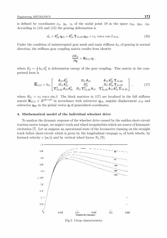
To analyze the dynamic response of the wheelset drive caused by the sudden short-circuittraction motor torque, we neglect track and wheel irregularities which are source of kinematicexcitation [7]. Let us suppose an operational state of the locomotive running on the straighttrack before short-circuit which is given by the longitudinal creepage s0 of both wheels, byforward velocity v [m/s] and by vertical wheel forces N0 [N].
Fig.5: Creep characteristics

174 Zeman V. et al.: Dynamic Load of the Locomotive Drive Caused by Short-Circuit Motor Torque
Longitudinal Ti ad, lateral Ai ad creep forces and spin torque Mi ad acting at the contactpatches between rails and wheels can be expressed as [12]
Ti ad = μ(si, v)Ni , Ai ad = b22 (ui+r ψi)+b23 ϑi , Mi ad = −b23 (ui+r ψi)+b33 ϑi . (18)
The longitudinal creep coefficient μ(si, v) depends on longitudinal creepage defined by
si = s0 +r ϕi − wi
v; s0 =
r ωW − v
v, (19)
where r is wheel radius. The lateral creep force and the spin torque about vertical axisdepend on linearized creep coefficients bij , calculated using Kalker’s theory [5] for static ver-tical wheel force before short-circuit. The creep force vectors in coordinate system xi, yi, zi
of corresponding wheel can be expressed in the form
fTi = [−Ai ad, Ni, Ti ad,−Ti ad r,−Mi ad,−Ai ad r] , i = 28, 30 . (20)
To analyze the wheelset drive vibration the longitudinal creep characteristics are presentedin Fig. 5. These characteristics express longitudinal creep coefficient depending up longi-tudinal creepage between the wheel and rail and the forward locomotive velocity v [km/h](v = 40, 80, 120, 160, 200). The characteristics in Fig. 5 are calculated for standard adhesionconditions and maximal normal pressure in wheel-rail contact ellipse according to Hertz’stheory on the basis of experimentally derived formula presented in [2], [10]. The longitudinalcreep coefficient will be linearized in the neighbourhood of a state before short-circuit in theform
μ(si, v) = μ(s0, v) +[∂μ
∂si
]si=s0
(s− s0) . (21)
The linearized longitudinal creep forces can be then expressed as
Ti ad = μ(s0, v)N0 + b11 (r ϕi − wi) ; b11 =3.6vN0
[∂μ
∂si
]si=s0
. (22)
According to (20) and (22) the linearized creep force vectors is
fi = −Bad qi + f0 , (23)
where matrix Bad and the static force vector f0 are in the form
Bad =
⎡⎢⎢⎢⎢⎢⎣b22 0 0 0 b23 r b220 0 0 0 0 00 0 b11 −r b11 0 00 0 −r b11 r2 b11 0 0
−b23 0 0 0 b33 −r b23r b22 0 0 0 r b23 r2 b22
⎤⎥⎥⎥⎥⎥⎦ ; f0 =
⎡⎢⎢⎢⎢⎢⎣0N0
μ0N0
−μ0N0 r00
⎤⎥⎥⎥⎥⎥⎦ . (24)
The vector of global linearized creep forces acting on both wheels in the configuration spaceof generalized coordinates is than
fad = −Bad(s0, v) q + f0 , (25)
whereBad(s0, v) = diag[ . . . ,Bad, . . . ,Bad, . . . ] ; f0 = [ . . . , f
T
0 , . . . , fT
0 , . . . ]T (26)

Engineering MECHANICS 175
with blocks Bad and subvectors f0 localized on positions corresponding to displacement qi,i = 28, 30 in the vector of generalized coordinates q(t). Other blocks and subvectors in (26)are zero.
According to the wheelset drive decomposition into 5 subsystems, modelling of the inter-nal couplings between subsystems and linearized creep forces in the neighbourhood of thestatic equilibrium before perturbation, the mathematical model of the wheelset drive can bewritten as
Mq + [B + BRM,S + BP,G + BS,BF + BDS + BCC + Bad(s0, v)] q +
+ [K + KRM,S + KP,G(dn) + KS,BF + KDS + KCC]q = fM(t) + f0 .(27)
Individual damping and stiffness matrices with subscripts correspond to coupling betweensubsystems (see Fig. 1) :
– RM,S – rotor, stator of the traction motor,– P,G – pinion gear, gearbox wheel,– S,BF – stator, bogie frame,– DS – disc clutch between gearbox wheel and hollow shaft,– CC – claw clutch between hollow shaft and wheelset.
Fig.6: Correction nonlinear stiffness function in gearing
The structure of global damping matrix B corresponds to stiffness matrix K in the blockdiagonal form presented in (4), whereas damping matrices are considered as proportional tocorresponding stiffness matrices
BRM = βRM KRM ; BH = βH KH ; BW = βW KW
and damping matrices of couplings have the same structure as stiffness coupling matrices.Under the assumption of viscous-elastic gearing including the gear mesh backlash, the re-sultant force FG transmitted by gearing can be approximately expressed in the followingform
F (dn) = kG dn + ΔF (dn) + bG dn , (28)
where bG approximately expresses viscous damping of oil film between teeth. Mathemati-cally, correction stiffness nonlinear function ΔF (dn) can be described over three piecewiselinear regimes [1] (see Fig. 6)
ΔF (dn) =
⎧⎪⎨⎪⎩0 for dn ≥ −dst ,
−kG(dn + dst) for − (dst + uG) ≤ dn ≤ −dst ,
kG uG for dn ≤ −(dst + uG) ,(29)

176 Zeman V. et al.: Dynamic Load of the Locomotive Drive Caused by Short-Circuit Motor Torque
where uG is gear mesh backlash and dst is the static gearing deformation at the time instantof the short-circuit beginning.
The global force vector of gear coupling in general coordinate space (5) can be writtenas
fG(t,q, q) = KP,G(dn)q + BP,G q , (30)
whereKP,G(dn)q = KP,G q + ΔF (dn) cG (31)
and vector cG meets the relation dn = cTG q. According to (16)
cG = [ . . . , δT16, . . . , rG cosα cosβ, δT
19 T19,20, . . . ]T . (32)
The damping matrix BP,G of gear coupling has the same structure as stiffness matrix KP,G
defined in (17), only stiffness coefficient kG is replaced by damping coefficient bG.
The motor torque during the short-circuit in the air-space of the traction motor is ap-proximated in the form [13]
M(t) = M(s0, v) −MC(t) , M(s0, v) = 2μ(s0, v)N0 rωW
ωM, (33)
where, using Heaviside function H(t), we can write
MC(t) = M(s0, v)H(t) +M0 e−DΩt sin[Ω(t− Δt)] . (34)
Fig.7: Function approximating the short-circuit torque
The oscillating short-circuit torque MC(t) (Fig. 7) is defined by amplitude M0, fre-quency Ω, shift phase Ω Δt and torque decay DΩ. The total motor torque after shorttime (here 0.2 [s]) is equal zero (MC = M(s0, v)).
The packet of sheet metals is modelled as a set of five rigid bodies mutually connectedwith translational, flexural and torsional springs identified on the basis of certain measure-ment [6]. The motor torque M(t) is described during the short-circuit in mathematicalmodel (27) in the form
fM(t) =M(t)
5[ . . . , 1, . . . , 1, . . . , 1, . . . , 1, . . . , 1, . . . , 5, . . . ]T (35)

Engineering MECHANICS 177
whereas digits 1 are localized on the positions corresponding to torsional displacements ofthe shaft nodal points 6 to 10 and digit 5 corresponds to stator torsional displacement ϕ20.Other coordinates symbolized by dots are zero. An opposite sense of the motor torque actingon stator is respected by the stator coordinate system (see Fig. 1).
5. Results of computer simulations
The condensed mathematical model of the wheelset drive with reduced DOF number isused for computer simulations. The DOF number reduction is based on modal transforma-tion of generalized coordinates
q(t) = mVx(t) , (36)
where mV ∈ Rn,m, m < n is modal submatrix of a conservative part of the linearizedmathematical model (27)
Mq(t) + (K + KRM,S + KP,G + KS,BF + KDS + KCC)q(t) = 0 (37)
satisfying the orthonormality conditions mVT M mV = E. The number of chosen mastereigenvectors included in modal submatrix is denoted m (m < n) and E is identity ma-trix of order m. The model (27) in new configuration space of dimension m by using thetransformation (36) and relation (31) can be then rewritten in the condensed form
x(t) + mVT BΣ(s0, v) mV x(t) + Λx(t) = mVT [fM(t) + f0 − ΔF (dn) cG] , (38)
where BΣ(s0, v) is the shortly marked global damping matrix in the model (27).
The condensed model has to fulfil desired demands on the accuracy. Although thismodel is nonlinear, we compare the dynamic response of the linearized condensed model(for uninterrupted gear mesh) with the dynamic response of noncondensed model usingaverage relative error
Δm,J =1nJ
N∑i=1
J∑j=1
|qi(tj) − q(m)i (tj)|
|qi(tj)| , tj ∈ 〈0;T 〉 . (39)
The influence of the DOF number m and of simulation time interval T [s] is visible inFig. 8. It is obvious that the condensation level given by m = 80 is suitable for a computersimulation.
Fig.8: Relative error

178 Zeman V. et al.: Dynamic Load of the Locomotive Drive Caused by Short-Circuit Motor Torque
Fig.9: Force transmitted by gearing
Fig.10: Dynamic force transmitted by silent block B
As an illustration, the time behaviour of chosen values in interval t ∈ 〈0; 0.2〉 [s] foroperational parameters s0 = 0.005, v = 200 [km/h] and N0 = 105 [N] at the instant of theshort-circuit are presented in Fig. 9 to Fig. 12. The frequency f = Ω/(2π) = 90 [Hz] of theoscilating short-circuit torque and lowest eigenfrequency f1 = 2.88 [Hz], corresponding tocouple of complex eigenvalues −0.0258±i·2.88 [Hz], show up as dominant. At the moment ofinterrupted gear mesh (t .= 0.08 [s]) the system becomes nonlinear. The dynamic responseof linearized (without of gear backlash) and real nonlinear model with gear backlash aremore (e.g. force transmitted by gearing in Fig. 9 and dynamic force transmitted by silentblock B in Fig. 10) or less (e.g. dynamic torsion deformation of the coupling between thering in nodal point 17 and the packet of sheet metals in Fig. 11 and dynamic radial forcetransmitted by bearing B2 in Fig. 12) different.
6. Conclusions
The paper describes the new method of mathematical modelling and computer simulationof the individual wheelset drive vibration of the electric locomotive caused by short-circuit

Engineering MECHANICS 179
Fig.11: Dynamic torsion deformation of the coupling betweenring in nodal point 17 and the packet of sheet metals
Fig.12: Dynamic component of the radial force transmitted by bearing B2 (see Fig. 1)
traction motor torque. The torsion, flexure and axial deformations of the motor shaft,flexibility of cooper bars connected sheet metal packet with short-circuit rings and flexibilityof the bearings of the rotor are newly respected. The sudden short-circuit in traction motorproduces a short-time, but large dynamic load of the wheelset drive components especially inthe driving part in front of the disc clutch. In view an extreme short-time internal loadingcan cause the gear mesh interruption in the gear transmission. This state is dangerousespecially for elastic supports of the stator to the bogie frame by silent blocks.
The developed software in MATLAB code enables graphically record the time behaviourof the arbitrary generalized coordinate and the forces transmitted by linkages betweenwheelset drive components. The dynamic response depends on operational parameters(especially on longitudinal creepage) at the instant just before the short-circuit. Funda-mentally worseness arises in the event of the short-circuit at large longitudinal creepage inthe downward section of the creep characteristics (see Fig. 5), when the system is unstable.The wheelset drive condensed mathematical model with reduced DOF number is a suitable

180 Zeman V. et al.: Dynamic Load of the Locomotive Drive Caused by Short-Circuit Motor Torque
instrument for computer simulations of the large nonlinear system in the case of interruptedgear mesh.
Acknowledgement
This paper has been elaborated in a framework of the projects MSMT 1M0519 – Researchcentre of Rail Vehicles and MSM 4977751303 of the Ministry of Education, Youth and Sportsof the Czech Republic.
References[1] Byrtus M., Zeman V.: On modeling and vibration of gear drives influenced by nonlinear
couplings, Mechanism and Machine theory, Vol.46 (2011), No. 3, 375–397[2] Cap J.: Some aspects of uniform comment of adhesion mechanism, Proceedings of VSCHT
Pardubice works, 1993, pp. 26–35 (in Czech)[3] Dvorak P.: Calculated values of the short-circuit moment in the air-space of the traction motor
ML 4550 K/6, Documentation of SKODA ELECTRIC a.s., Plzen, 2009 (in Czech)[4] Feldman V. et all.: Monitoring the dynamic of railway track by means of the Karhunen-Loeve-
transfomation, in System Dynamics and Long Term Behaviour of Railway Vehicles, Track andSubgrade (K. Popp and W. Schiehlen eds.), Springer, 2003, pp. 231–246
[5] Garg V., Dukkipati R.: Dynamics of railway vehicle systems, London Academic Press 1984,Toronto
[6] Hajzman M., Byrtus M., Zeman V.: Development of the basic dynamical model of a squirrelcage motor, Engineering Mechanics, Vol. 17 (2010), No. 3/4, 161–172
[7] Hlavac Z., Zeman V.: Optimization of the railway vehicle bogie in term of dynamic, Appliedand Computational Mechanics, 1 (3) (2009), 39–50
[8] Jockel A.: Aktive Dampfung von Ratterschwingungen in Antriebstrang von Lokomotive mitDrehstrom-Antriebstechnik, ZEV + DET Glas. Ann., 125 (5) (2001), 191–204
[9] Lata M.: Modelling of transient processes in torsion drive system of railway vehicle, ScientificPapers of the University of Pardubice, Series B, 2003, pp. 45–58 (in Czech)
[10] Lata M.: Dynamic processes in electric locomotive drive on rise of the wheelset slip, Book ofExtended Abstracts of the Conference Engineering Mechanics 2004, Svratka, pp. 165–166, (fullpaper on CD-ROM)
[11] Slavık J., Stejskal V., Zeman V.: Dynamic of machines principles, CTU Publishing House1997, Praha (in Czech)
[12] Zeman V., Hlavac Z., Byrtus M.: Modelling of wheelset drive vibration of locomotive 109E,Research report n. H2,H6-06-01/2006, Research Centre of Rail Vehicles, Plzen, 2007 (in Czech)
[13] Zeman V., Hlavac Z.: Dynamic wheelset drive load of the railway vehicle caused by short-circuit motor moment, Applied and Computational Mechanics, Vol. 3 (2009), No. 2, 423–434
Received in editor’s office : March 17, 2011Approved for publishing : May 4, 2011
Note : This paper is an extended version of the contribution presented at the nationalcolloquium with international participation Dynamics of Machines 2011 in Prague.