Embed Size (px)
Citation preview
Dynamic Power Profile Estimation of InterconnectedSmart Objects
Suresh Kumar N1,Siju Koshy2,G. Santhosh Kumar3Department of Computer Science
Cochin University ofScience And Technology(CUSAT)
Kochi, IndiaEmail: {sureshkumar1,san3}@cusat.ac.in, [email protected]
Abstract—Networked embedded objects augmented withsmart applications have already started encompassing manyaspects of human life. More often these objects are drivenby limited power sources and hence estimation of remainingenergy in these objects at run time becomes important. Alsopower profiling provides a rough idea on how long the intendedapplications will run on the network given the battery-lifespecification. The proposed component based architecture usea power estimation module for dynamic power profiling. Thecode for power estimation could be disseminated either throughdirect burning or over-the-air programming in each objects ofthe network. The scheme has been implemented and tested ona wireless sensor network set-up where smart objects consideredare TelosB nodes running on Contiki operating system. Theexperiment conducted, the results and observations are presented.
I. INTRODUCTION
Internet of Things (IoT) is an ecosystem of networkedembedded systems with capabilities of computation, com-munication, sensing and actuation. Applications run on thisencompass all aspects of human life enabling smart living.These smart devices are driven by battery power and this hasbecome one of the limitations on prolonged operation of thenetwork. Application developers should have an idea on howlong the network will provide service before replacement ofenergy source of the nodes. Statistics on power consumptionof components in the network would be helpful in this. Manya times the untethered operation of such devices makes itdifficult to get a direct estimation of remaining battery powerof these nodes. Power profiling of nodes at the system level hasbeen discussed in [6] [5] [10]. This can be extended by lever-aging dynamic linking/loading and over-the-air programmingto achieve power profiling of already deployed applications.Architecture for dynamic power profiling of the nodes inthe network attached along with applications either throughdirect embedding or over-the-air programming is discussedhere. Power profiling of the network can be dynamicallycontrolled using a stub module. Energy estimation of a nodehas been done by separating hardware component level powerconsumption and remaining battery voltage so as to estimatecomponent level power consumption during the applicationtesting phase and remaining battery voltage during run-time.This helps in determining whether an application satisfiesthe power requirements specified by the application providerdynamically. The proposed scheme has been implemented and
tested on a wireless sensor network set-up where smart objectsconsidered are TelosB [13] nodes running on Contiki operatingsystem. Rest of the paper is organized as follows. Section IIdiscusses the related works. The proposed architecture and thecomponent level description for implementing dynamic powerprofiling was presented in section III. The experimental set upand the various steps involved in implementing the architecturealong with results are presented in section IV. Section discussconclusions and future work. The experiment conducted, theresults and observations are presented.
II. RELATED WORKS
1) Energy Estimation: Energy consumption is one of theimportant factor in sensor nodes. But the evaluation of energyconsumption of an already running application is challenging.Manual intervention is required for hardware based energymeasurement mechanisms which may increases the mainte-nance cost and time. One of the simplest method of energyestimation is software based energy estimation mechanism[5]. In software based energy measurement mechanism, thetotal energy is considered as the energy spent on differentcomponents of a node. The components are CPU in activemode, CPU in sleep mode, Radio in transmit mode, Radioin listening mode and the energy of LEDs. The total energyconsumption of a sensor node is defined as [5]
E
V= Imtm + Iltl + Ittt + Irtr +
∑i
Icitci (1)
where V is the operational voltage, Im is the current draw ofthe CPU in active mode, tm is the time in which the CPUis running in active mode, Il is the current draw of CPU insleep mode, tl is the time in which the CPU is running insleep mode, It and tt is the current draw and time of the radiocomponent in transmit mode, Ir and tr is the current draw andtime of the radio component in listening mode and Ici and tciis the current draw and time of other node components suchas sensors, LEDs.
2) Run-time Dynamic Linking: Most of the WSN devicesare resource constrained devices in terms of memory, pro-cessing power and communication capability. The behaviorof these nodes are determined by the software running onthe programmable radio equipped embedded systems in the978-1-4673-6670-0/15/$31.00 c©2015 IEEE
394
2015 IEEE Recent Advances in Intelligent Computational Systems (RAICS) | 10-12 December 2015 | Trivandrum
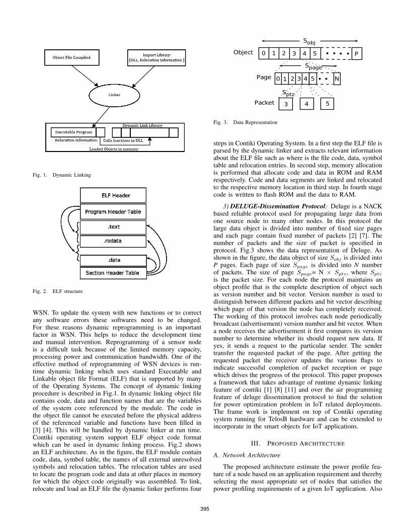
Fig. 1. Dynamic Linking
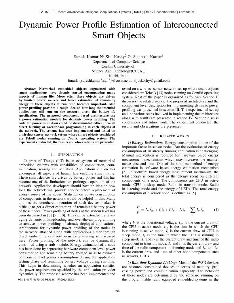
Fig. 2. ELF structure
WSN. To update the system with new functions or to correctany software errors these softwares need to be changed.For these reasons dynamic reprogramming is an importantfactor in WSN. This helps to reduce the development timeand manual intervention. Reprogramming of a sensor nodeis a difficult task because of the limited memory capacity,processing power and communication bandwidth. One of theeffective method of reprogramming of WSN devices is run-time dynamic linking which uses standard Executable andLinkable object file Format (ELF) that is supported by manyof the Operating Systems. The concept of dynamic linkingprocedure is described in Fig.1. In dynamic linking object filecontains code, data and function names that are the variablesof the system core referenced by the module. The code inthe object file cannot be executed before the physical addressof the referenced variable and functions have been filled in[3] [4]. This will be handled by dynamic linker at run time.Contiki operating system support ELF object code formatwhich can be used in dynamic linking process. Fig.2 showsan ELF architecture. As in the figure, the ELF module containcode, data, symbol table, the names of all external unresolvedsymbols and relocation tables. The relocation tables are usedto locate the program code and data at other places in memoryfor which the object code originally was assembled. To link,relocate and load an ELF file the dynamic linker performs four
Fig. 3. Data Representation
steps in Contiki Operating System. In a first step the ELF file isparsed by the dynamic linker and extracts relevant informationabout the ELF file such as where is the file code, data, symboltable and relocation entries. In second step, memory allocationis performed that allocate code and data in ROM and RAMrespectively. Code and data segments are linked and relocatedto the respective memory location in third step. In fourth stagecode is written to flash ROM and the data to RAM.
3) DELUGE-Dissemination Protocol: Deluge is a NACKbased reliable protocol used for propagating large data fromone source node to many other nodes. In this protocol thelarge data object is divided into number of fixed size pagesand each page contain fixed number of packets [2] [7]. Thenumber of packets and the size of packet is specified inprotocol. Fig.3 shows the data representation of Deluge. Asshown in the figure, the data object of size Sobj is divided intoP pages. Each page of size Spage is divided into N numberof packets. The size of page Spage= N × Sptz , where Sptz
is the packet size. For each node the protocol maintains anobject profile that is the complete description of object suchas version number and bit vector. Version number is used todistinguish between different packets and bit vector describingwhich page of that version the node has completely received.The working of this protocol involves each node periodicallybroadcast (advertisement) version number and bit vector. Whena node receives the advertisement it first compares its versionnumber to determine whether its should request new data. Ifyes, it sends a request to the particular sender. The sendertransfer the requested packet of the page. After getting therequested packet the receiver updates the various flags toindicate successful completion of packet reception or pagewhich drives the progress of the protocol. This paper proposesa framework that takes advantage of runtime dynamic linkingfeature of contiki [1] [8] [11] and over the air programmingfeature of deluge dissemination protocol to find the solutionfor power optimization problem in IoT related deployments.The frame work is implement on top of Contiki operatingsystem running for TelosB hardware and can be extended toincorporate in the smart objects for IoT applications.
III. PROPOSED ARCHITECTURE
A. Network Architecture
The proposed architecture estimate the power profile fea-ture of a node based on an application requirement and therebyselecting the most appropriate set of nodes that satisfies thepower profiling requirements of a given IoT application. Also
395
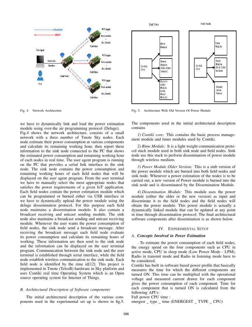
Fig. 4. Network Architecture
we have to dynamically link and load the power estimationmodule using over-the air programming protocol (Deluge).Fig.4 shows the network architecture, consists of a smallnetwork with a three number of Tmote Sky nodes. Eachnode estimate their power consumption at various componentsand calculate its remaining working hour, then report theseinformation to the sink node connected to the PC that showsthe estimated power consumption and remaining working hourof each nodes in real time. The user agent program is runningon the PC that provides a serial link interface to the sinknode. The sink node contains the power consumption andremaining working hours of each field nodes that will bedisplayed on the user agent program. From the user terminalwe have to manually select the most appropriate nodes thatsatisfies the power requirements of a given IoT application.Each field nodes contain the power estimation module whichcan be programmed or burned either via USB interface orwe have to dynamically upload the power module using thedeluge dissemination protocol. For this purpose each fieldnode maintains a dissemination module. It also contain abroadcast receiving and unicast sending module. The sinknode also maintains a broadcast sending and unicast receivingmodule. Whenever the user wants the power consumption offield nodes, the sink node send a broadcast message. Afterreceiving the broadcast message each field node evaluateits power consumption and calculate its remaining hours ofworking. These information are then send to the sink nodeand the information can be displayed on the user terminalprogram. Communication between the sink node and the userterminal is established through serial interface, while the fieldnode establish wireless communication to the sink node. Eachfield node is identified by the rime id[12]. This project isimplemented in Tmote (TelosB) hardware in Sky platform anduses Contiki real time Operating System which is an Opensource operating system for Internet of Things.
B. Architectural Description of Software components
The initial architectural description of the various com-ponents used in the experimental set up is shown in fig.5.
Fig. 5. Architecture With Old Version Of Power Module
The components used in the initial architectural descriptioncontains
1) Contiki core: This contains the basic process manage-ment module and timer modules used by Contiki.
2) Rime Module: It is a light weight communication proto-col stack module used in both sink node and field nodes. Sinknode use this stack to perform dissemination of power modulethrough wireless medium.
3) Power Module Older Version: This is a stub version ofthe power module which are burned into both field nodes andsink node. Whenever a power estimation of the nodes is to becarried out, a new version of Power module is burned into thesink node and is disseminated by the Dissemination Module.
4) Dissemination Module: This module uses the powermodule (either the older or the new version) as input anddisseminate it to the field nodes and the field nodes willobtain the power module. This power module is actually adynamically linked module that can be updated at any pointin time through dissemination protocol. The final architecturalsoftware components after dissemination is as shown below.
IV. EXPERIMENTAL SETUP
A. Concepts Involved in Power Estimation
. To estimate the power consumption of each field nodes,the energy spend on the four components such as CPU inactive mode, CPU in sleep mode (Low Power Mode - LPM),Radio in transmit mode and Radio in listening mode have tobe considered.Contiki has built in software based power profile that basicallymeasures the time for which the different components areturned ON. This time can be multiplied with the operationalvoltage and measured current drawn for each componentgives the power consumption of each component. Time foreach component that is turned ON is calculated from thefollowing API’s:Full power CPU time :energest type time (ENERGEST TYPE CPU)
396

Fig. 6. Architecture With New Version Of Power Module
TABLE I. CURRENT DRAWN FOR EACH COMPONENT
Component State Current
CPU Active - MCU on, Radio off 1.8 mA (I cpu)LPM Sleep - MCU idle, Radio off 0.0545 mA (I lpm)Radio Transmitter (TX) 19.5 mA (I tx)Radio Receiver (RX) 21.8 mA (I rx)
Reduced power CPU time:energest type time (ENERGEST TYPE LPM)Radio transmit time:energest type time (ENERGEST TYPE TRANSMIT)Radio receiving time:energest type time (ENERGEST TYPE LISTEN).Table I shows [9] [14] the current drawn for each components.For example power consumption of radio in listening modein mW is:
P rx = (rxend− rxstart)× I rx× V op× 1
N ticks(2)
where (rxend-rxstart) is the time for which the radio receivercomponent is turned ON, I rx is the previously measuredcurrent draw of the radio receiver component in milliampere,V op is the operational voltage of Tmote in volt and N ticks isthe number of ticks per second. Similarly we have to calculatethe energy consumption of all other components. The totalpower consumption is the sum of power consumption of eachcomponent:
P components = P cpu+ P lpm+ P tx+ P rx (3)
After evaluating the power consumption of each component itis required to calculate the remaining working hours of node inwhich the application will run. It can be calculated by findingout the remaining battery voltage in (mV) of deployed nodeby using the equation as
b voltage = (average battery voltage∗c factor)/N ticks(4)
where average battery voltage is the average value of batteryvoltage captured from ADC by repeatedly polling the batteryvoltage, c factor is the scaling factor for converting the voltage
to millivolts and N ticks is the number of clock ticks. Thebattery power remaining in the node is calculated by using theequation as
power remaining = b voltage ∗ battery capacity (5)
where battery capacity is the capacity of the battery in (mAH)and can be obtained from the data sheet. The remaining timethe application will run on the node can be calculated as
t application =power remaining
P components(6)
B. Dissemination of Power Module
The steps involved in the dissemination of power moduleincludes
1) Compile and Upload the Contiki executable to the Sinknode: This involves compiling the power application as aContiki executable by using the commandmake compile-executable.Contiki executable is then uploaded to the sink node using thecommandmake upload executable
2) Transfer of Contiki executable to the Field node: Thisinvolves running the deluge dissemination protocol on the sinknode. The input file used by the deluge protocol is the powermodule in elf format that was uploaded into the node by thestep mentioned above.
C. Dynamic Linking and Loading of Power EstimationModule
Once the power module (.ce) is disseminated in the fieldnode, the next method is to link and load the module dynam-ically at run time. The programming interfaces for loadingthe program uses Executable Linkable Format (ELF) and itinvolves the following steps
1) Loading ELF Module: In contiki the API’s necessaryfor loading ELF module is defined in core/loader/elfloader.h.The various steps involved are as follows [15]
• Initialize the dynamic loader library by int elfloaderinit (void) function
• The next step is to load the file by using the functionelfloader load() with a Contiki File System (CFS) filedescriptor of the open file as the only argument. Ifthe dynamic loading succeeds, elfloader load() returnsELFLOADER OK, otherwise it returns error mes-sage.
• Finally the loaded process is automatically started byusing the function elfloader autostart processes()
2) Preparing a Firmware for ELF Loading: Contiki in-cludes an empty symbol table so that the code size is notexpanded unnecessarily. Therefore, the symbol table must begenerated and included within firmware that intends to loadELF modules. The commands needed to generate such afirmware are shown below. This three step process ensuresthat all available symbols in the firmware are also visible inthe symbol table, along with a pointer to their address and isshown below.
397
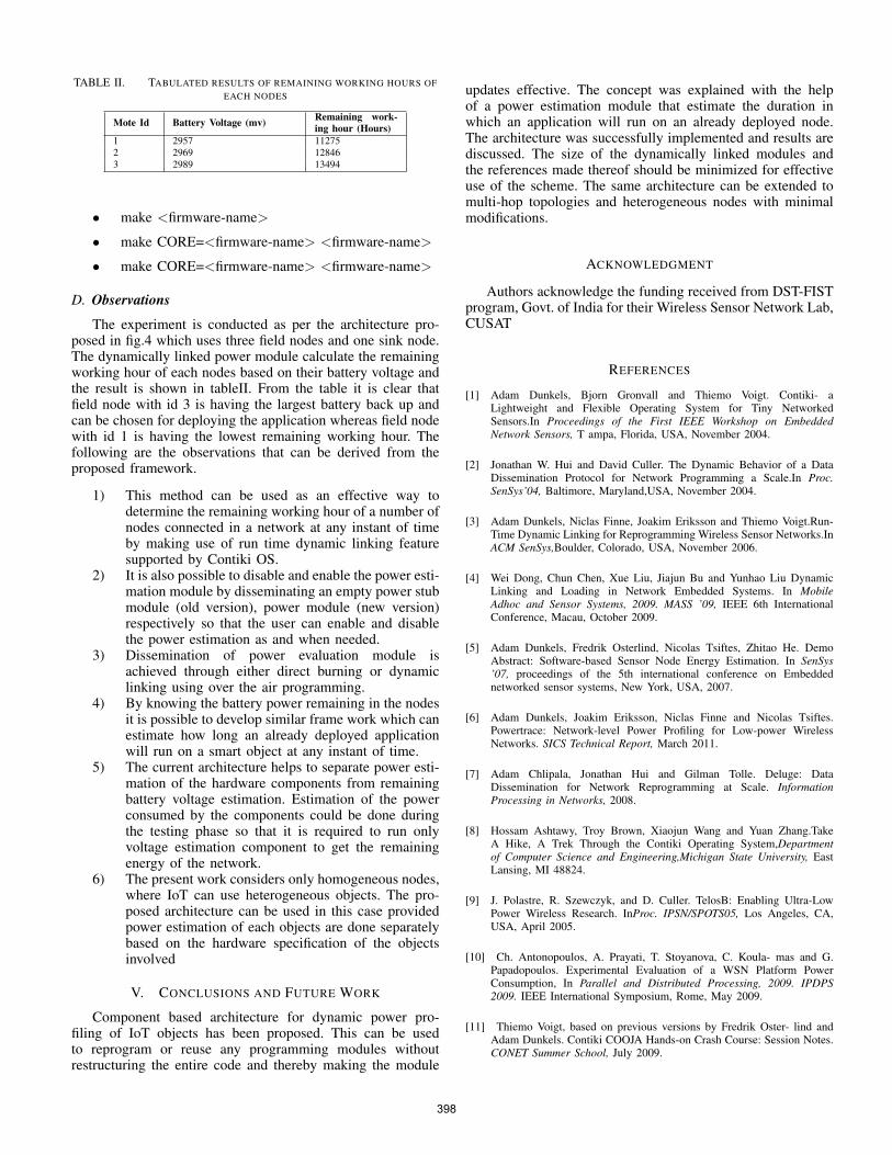
TABLE II. TABULATED RESULTS OF REMAINING WORKING HOURS OFEACH NODES
Mote Id Battery Voltage (mv) Remaining work-ing hour (Hours)
1 2957 112752 2969 128463 2989 13494
• make <firmware-name>
• make CORE=<firmware-name> <firmware-name>
• make CORE=<firmware-name> <firmware-name>
D. Observations
The experiment is conducted as per the architecture pro-posed in fig.4 which uses three field nodes and one sink node.The dynamically linked power module calculate the remainingworking hour of each nodes based on their battery voltage andthe result is shown in tableII. From the table it is clear thatfield node with id 3 is having the largest battery back up andcan be chosen for deploying the application whereas field nodewith id 1 is having the lowest remaining working hour. Thefollowing are the observations that can be derived from theproposed framework.
1) This method can be used as an effective way todetermine the remaining working hour of a number ofnodes connected in a network at any instant of timeby making use of run time dynamic linking featuresupported by Contiki OS.
2) It is also possible to disable and enable the power esti-mation module by disseminating an empty power stubmodule (old version), power module (new version)respectively so that the user can enable and disablethe power estimation as and when needed.
3) Dissemination of power evaluation module isachieved through either direct burning or dynamiclinking using over the air programming.
4) By knowing the battery power remaining in the nodesit is possible to develop similar frame work which canestimate how long an already deployed applicationwill run on a smart object at any instant of time.
5) The current architecture helps to separate power esti-mation of the hardware components from remainingbattery voltage estimation. Estimation of the powerconsumed by the components could be done duringthe testing phase so that it is required to run onlyvoltage estimation component to get the remainingenergy of the network.
6) The present work considers only homogeneous nodes,where IoT can use heterogeneous objects. The pro-posed architecture can be used in this case providedpower estimation of each objects are done separatelybased on the hardware specification of the objectsinvolved
V. CONCLUSIONS AND FUTURE WORK
Component based architecture for dynamic power pro-filing of IoT objects has been proposed. This can be usedto reprogram or reuse any programming modules withoutrestructuring the entire code and thereby making the module
updates effective. The concept was explained with the helpof a power estimation module that estimate the duration inwhich an application will run on an already deployed node.The architecture was successfully implemented and results arediscussed. The size of the dynamically linked modules andthe references made thereof should be minimized for effectiveuse of the scheme. The same architecture can be extended tomulti-hop topologies and heterogeneous nodes with minimalmodifications.
ACKNOWLEDGMENT
Authors acknowledge the funding received from DST-FISTprogram, Govt. of India for their Wireless Sensor Network Lab,CUSAT
REFERENCES
[1] Adam Dunkels, Bjorn Gronvall and Thiemo Voigt. Contiki- aLightweight and Flexible Operating System for Tiny NetworkedSensors.In Proceedings of the First IEEE Workshop on EmbeddedNetwork Sensors, T ampa, Florida, USA, November 2004.
[2] Jonathan W. Hui and David Culler. The Dynamic Behavior of a DataDissemination Protocol for Network Programming a Scale.In Proc.SenSys’04, Baltimore, Maryland,USA, November 2004.
[3] Adam Dunkels, Niclas Finne, Joakim Eriksson and Thiemo Voigt.Run-Time Dynamic Linking for Reprogramming Wireless Sensor Networks.InACM SenSys,Boulder, Colorado, USA, November 2006.
[4] Wei Dong, Chun Chen, Xue Liu, Jiajun Bu and Yunhao Liu DynamicLinking and Loading in Network Embedded Systems. In MobileAdhoc and Sensor Systems, 2009. MASS ’09, IEEE 6th InternationalConference, Macau, October 2009.
[5] Adam Dunkels, Fredrik Osterlind, Nicolas Tsiftes, Zhitao He. DemoAbstract: Software-based Sensor Node Energy Estimation. In SenSys’07, proceedings of the 5th international conference on Embeddednetworked sensor systems, New York, USA, 2007.
[6] Adam Dunkels, Joakim Eriksson, Niclas Finne and Nicolas Tsiftes.Powertrace: Network-level Power Profiling for Low-power WirelessNetworks. SICS Technical Report, March 2011.
[7] Adam Chlipala, Jonathan Hui and Gilman Tolle. Deluge: DataDissemination for Network Reprogramming at Scale. InformationProcessing in Networks, 2008.
[8] Hossam Ashtawy, Troy Brown, Xiaojun Wang and Yuan Zhang.TakeA Hike, A Trek Through the Contiki Operating System,Departmentof Computer Science and Engineering,Michigan State University, EastLansing, MI 48824.
[9] J. Polastre, R. Szewczyk, and D. Culler. TelosB: Enabling Ultra-LowPower Wireless Research. InProc. IPSN/SPOTS05, Los Angeles, CA,USA, April 2005.
[10] Ch. Antonopoulos, A. Prayati, T. Stoyanova, C. Koula- mas and G.Papadopoulos. Experimental Evaluation of a WSN Platform PowerConsumption, In Parallel and Distributed Processing, 2009. IPDPS2009. IEEE International Symposium, Rome, May 2009.
[11] Thiemo Voigt, based on previous versions by Fredrik Oster- lind andAdam Dunkels. Contiki COOJA Hands-on Crash Course: Session Notes.CONET Summer School, July 2009.
398
[12] Adam Dunkels. Poster Abstract: Rime A Lightweight LayeredCommunication Stack for Sensor Networks. Proceedings of the EuropeanConference on Wireless Sensor Networks (EWSN), Poster/Demosession,January 2007.
[13] TelosB-Ultra low power IEEE 802.15.4 compliant wireless sensormodule”, Datasheet, MoteIV Corporation.
[14] http://www.willow.co.uk/TelosB Datasheet.pdf, Cross-bow Technology,TelosB Mote Platform
[15] https://github.com/contiki-os/contiki/wiki/The-dynamic- loader. TheDynamic loader.
399