Embed Size (px)
Citation preview
Dynamic Simulation and Simulation Tools Development of Oxyfuel-CFB Power Plant
2nd International Workshop on Oxyfuel FBC Technology Antti Tourunen, Jari Lappalainen, Hannu Mikkonen, Jouni Savolainen and Mikko JegoroffVTT Technical Research Centre of Finland
209/07/2012
Content
Background
Objective
Development of dynamic simulator for oxyfuel CFB power plant
Application of the simulator – case examples
Conclusions
309/07/2012
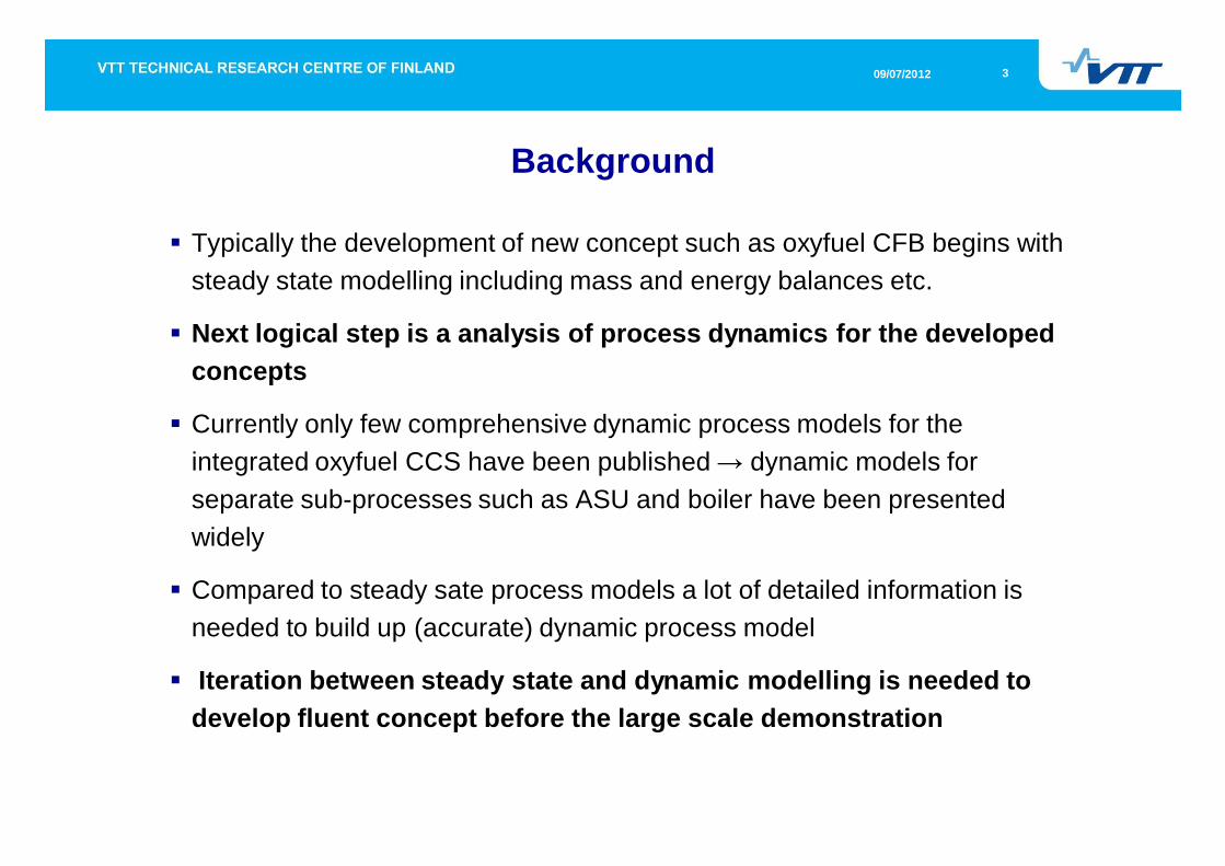
Typically the development of new concept such as oxyfuel CFB begins with steady state modelling including mass and energy balances etc.
Next logical step is a analysis of process dynamics for the developed concepts
Currently only few comprehensive dynamic process models for the integrated oxyfuel CCS have been published dynamic models for separate sub-processes such as ASU and boiler have been presented widely
Compared to steady sate process models a lot of detailed information is needed to build up (accurate) dynamic process model
Iteration between steady state and dynamic modelling is needed to develop fluent concept before the large scale demonstration
Background
409/07/2012
Objectives for the development of the dynamic simulator
The primary target is to provide information on dynamic behaviour of the integrated system
This information is essential for verifying the feasibility of the process concept and its control strategies from low level to upper level controllers
Operability of the novel concept must be studied and guaranteed before large investment in demonstration unit
Solid understanding of the plant dynamics is needed to develop advanced high level controls
Dynamic simulation supports this task by providing dynamic response data for required variables
509/07/2012
Selection of software (1/2)
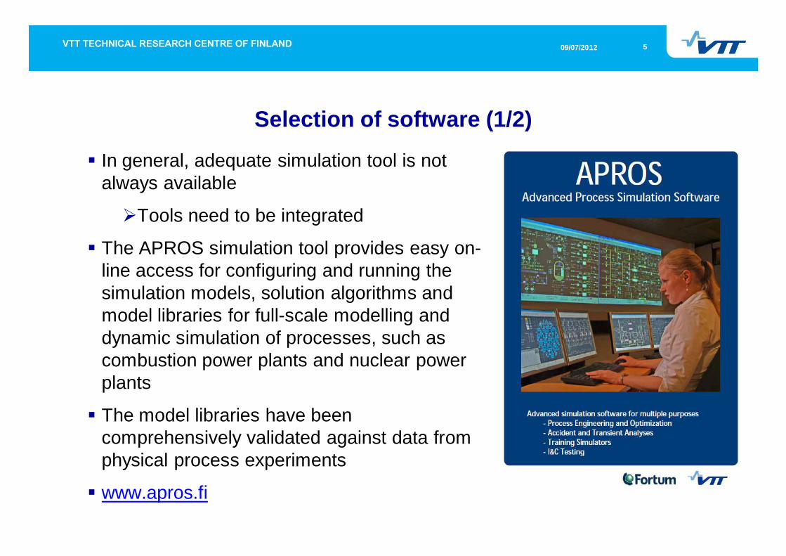
In general, adequate simulation tool is not always available
Tools need to be integrated
The APROS simulation tool provides easy on-line access for configuring and running the simulation models, solution algorithms and model libraries for full-scale modelling and dynamic simulation of processes, such as combustion power plants and nuclear power plants
The model libraries have been comprehensively validated against data from physical process experiments
www.apros.fi
609/07/2012
Selection of software (2/2)
Aspen Plus® Dynamics is a very powerful tool to model chemical processes such as distillation processes needed for oxyfuel CCS plant
Objective was to combine the best part of the softwares (Apros and Aspen Plus Dynamics) in order to simulate the modern process concepts with the best possible tools
Power plants with APROS
Chemical plants with Aspen
709/07/2012
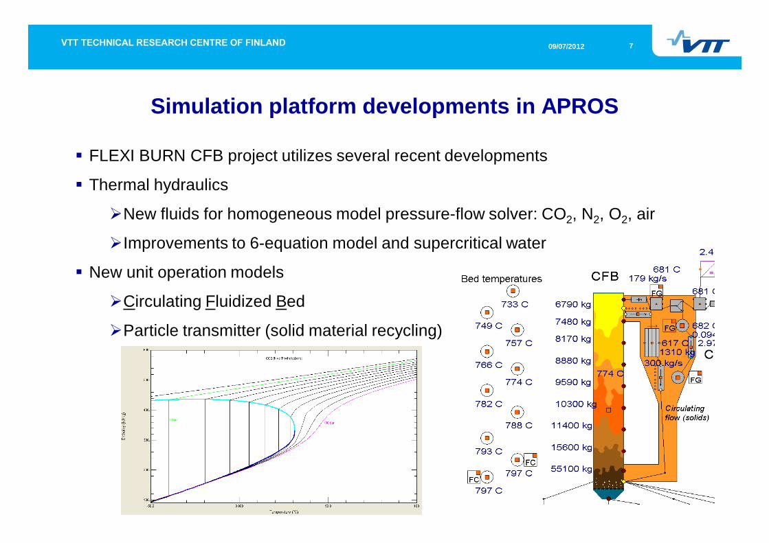
FLEXI BURN CFB project utilizes several recent developments
Thermal hydraulics
New fluids for homogeneous model pressure-flow solver: CO2, N2, O2, air
Improvements to 6-equation model and supercritical water
New unit operation models
Circulating Fluidized Bed
Particle transmitter (solid material recycling)
Simulation platform developments in APROS
809/07/2012
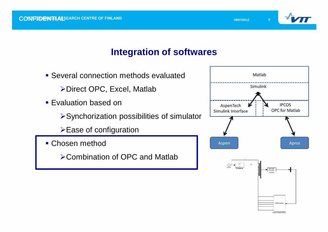
Several connection methods evaluated
Direct OPC, Excel, Matlab
Evaluation based on
Synchorization possibilities of simulator
Ease of configuration
Chosen method
Combination of OPC and Matlab
Integration of softwares
CONFIDENTIAL
909/07/2012
Development of dynamic simulator
A dynamic tool combining Apros and Aspen Dynamics simulators of the process integrate that covers ASU (Air separation unit), CFB (circulating fluidized bed boiler) with turbine Island, and CPU (CO2 compression and purification unit) was developed
The model includes the main process units and streams of the process to provide the characteristic dynamic features of the system
The control loops and supporting calculations that were essentially required to operate the system are included
1009/07/2012
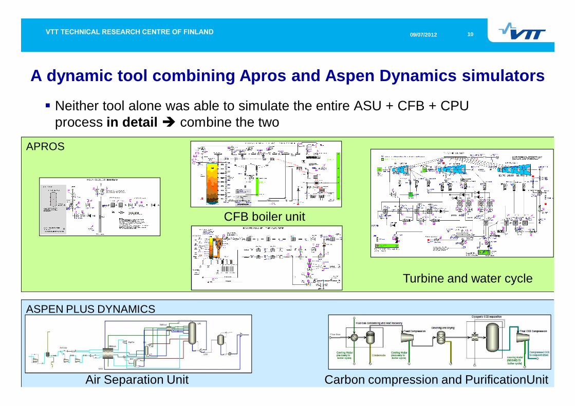
A dynamic tool combining Apros and Aspen Dynamics simulators
Neither tool alone was able to simulate the entire ASU + CFB + CPU process in detail combine the two
APROS
ASPEN PLUS DYNAMICS
Air Separation Unit Carbon compression and PurificationUnit
CFB boiler unit
Turbine and water cycle
1109/07/2012
Dynamic simulation of oxyfuel CFB power plant
Typically simulation studies include operation transients, such as
start-up and shut-down,
load changes,
various disturbance situations,
changes between air- and oxygen-firing
Comparison and analysis of air- and oxygen-firing in above mentioned situations
special features of oxygen-firing e.g. effect of high flue gas recirculation on boiler behaviour and control system
coordination and upper level controls for the integrated power plant including ASU, boiler and CPU
1209/07/2012
SIMULATION EXAMPLE 1:
LOAD CHANGE -5%
1309/07/2012
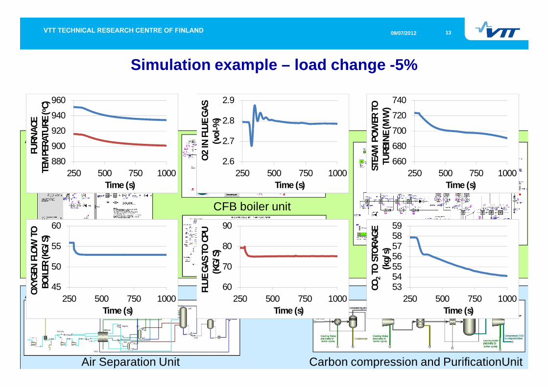
Simulation example – load change -5%
APROS
ASPEN PLUS DYNAMICS
Air Separation Unit Carbon compression and PurificationUnit
CFB boiler unit
Turbine and water cycle
45
50
55
60
250 500 750 1000
OXY
GEN
FLO
W T
O
BOIL
ER (K
G/S
)
Time (s)
60
70
80
90
250 500 750 1000
FLU
E G
AS
TO C
PU
(KG
/S)
Time (s)
880
900
920
940
960
250 500 750 1000
FURN
ACE
TE
MPE
RATU
RE (o C
)
Time (s)
53545556575859
250 500 750 1000
CO2
TO S
TORA
GE
(kg/
s)
Time (s)
660
680
700
720
740
250 500 750 1000STEA
M P
OW
ER T
O
TURB
INE
(MW
)
Time (s)
2.6
2.7
2.8
2.9
250 500 750 1000
O2
IN F
LUE
GA
S (v
ol-%
)
Time (s)
1409/07/2012
SIMULATION EXAMPLE 2:
MODE CHANGE FROM AIR TO OXY AND BACK
1509/07/2012
Simulation example: Mode change from air to oxy and back
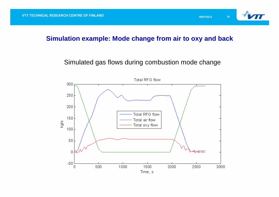
Mode change from air mode to oxy mode and back again
The manipulated variables:
Air flows
Oxygen flows
RFG flows
(Fuel feed is constant)
During the changes all the set points for primary air, secondary air, primary RFG-gas secondary RFG-gas, primary oxygen and secondary oxygen flows are ramped up/down with same ramping rate
Duration of transitions about 9 min
1609/07/2012
Simulation example: Mode change from air to oxy and back
Simulated gas flows during combustion mode change
1709/07/2012
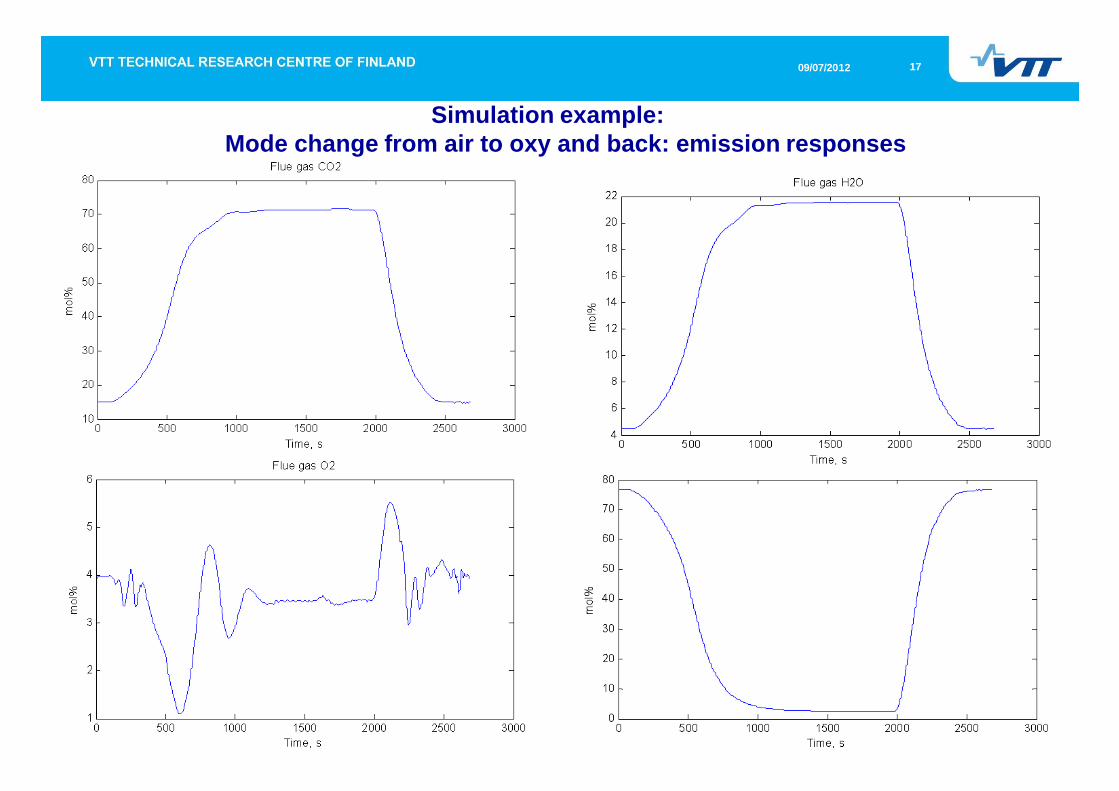
Simulation example: Mode change from air to oxy and back: emission responses
1809/07/2012
Conclusions (1/2)
Time dependent process model was developed for Oxyfuel CFB power plant including ASU, boiler island and CPU
Simulation of the concept with best possible tools
Power plants with APROS
Chemical plants with Aspen
The model performance was tested by simulating load changes and transitions between air and oxy modes
The model provides excellent base to study dynamical behaviour of the oxyfuel CFB power plant with CCS and to develop and optimize control strategies, upper level controls, and operational practises
1909/07/2012
Conclusions (2/2)Dynamic simulation of the integrated oxyfuel CFB power plant with CCS is very important in order to guarantee high availability combined with high efficiency and safety operation
e.g. the interface between ASU and the boiler island proved to be very important part of the system from control and operation point of view
Further development of oxyfuel CCS concepts call for dynamic simulators
e.g. development of the second generation of oxyfuel CFB power plant concept with significantly higher efficiency
Future developments in simulation tools
Need to improve integration of different simulation tools e.g. ASPEN and APROS without matlab link
Further development of submodels for ASU, boiler and CPU
Acknowledgements for FLEXI BURN CFB:The research leading to these results has received funding from the European Community’s Seventh Framework Programme (FP7/2007-2013) under grant agreement n° 239188.

2009/07/2012
VTT - 70 years oftechnology for business
and society