Embed Size (px)
Citation preview

Dynamics of rocking podium structures
J.A. Bachmann*,† , M.F. Vassiliou and B. Stojadinović
Institute of Structural Engineering (IBK), Swiss Federal Institute of Technology (ETHZ), Stefano-Franscini-Platz 5, 8093Zurich, Switzerland
SUMMARY
A rocking podium structure is a class of structures consisting of a superstructure placed on top of a rigid slabsupported by free-standing columns. The free-standing columns respond to sufficiently strong groundmotion excitation by uplifting and rocking. Uplift works as a mechanical fuse that limits the forcestransmitted to the superstructure, while rocking enables large lateral displacements. Such ‘soft-story’ systemruns counter to the modern seismic design philosophy but has been used to construct several hundredbuildings in countries of the former USSR following Polyakov’s rule-of-thumb guidelines: (i) that thesuperstructure behave as a rigid body and (ii) that the maximum lateral displacement of the rocking podiumframe be estimated using elastic earthquake displacement response spectra. The objectives of this paper areto present a dynamic model for analysis of the in-plane seismic response of rocking podium structures and toinvestigate if Polyakov’s rule-of-thumb guidelines are adequate for the design of such structures.Examination of the rocking podium structure response to analytical pulse and recorded ground motionexcitations shows that the rocking podium structures are stable and that Polyakov’s rule-of-thumb guidelinesproduce generally conservative designs. Copyright © 2017 John Wiley & Sons, Ltd.
Received 17 February 2017; Revised 7 April 2017; Accepted 15 April 2017
KEY WORDS: rocking structural systems; in-plane seismic response; design guidelines
1. INTRODUCTION
Structures fixed to the ground using foundation systems that prevent uplift and sliding dominatemodern seismic design. However, two distinctly different seismic design concepts have emergedover the last half century. One is the concept of seismic base isolation, where an additional softlayer is inserted between the foundation and the superstructure and is specially designed such that itcan take most of the seismic displacement demand. Consequently, the seismic demands in theisolated superstructure are decreased, allowing for better-performing and safer structures.
The other concept centers on allowing the structure to uplift from its foundation and rock inresponse to ground motion excitation. Uplift serves as a mechanical fuse, limiting the forcestransmitted to the structure and the foundation, while the energy of the input ground motion isdissipated through impacts at the rocking interfaces. The size effect (larger rocking structures aremore stable) and the lack of residual displacements are two remarkable dynamic properties ofrocking structures. The pioneering rocking structures have been investigated, designed, and built inNew Zealand [1, 2], Russia and the USSR [3], and the USA [4] in 1970s.
Modern rocking buildings evolved in two directions. One direction, developed mainly by NorthAmerican and New Zealand engineers, focuses on controlling the displacements of rocking buildingsusing a variety of mechanical restrainers (e.g., post-tensioning cables and yielding bolts) and/or
*Correspondence to: Institute of Structural Engineering (IBK), Swiss Federal Institute of Technology (ETHZ), Stefano-Franscini-Platz 5, 8093 Zurich, Switzerland.†E-mail: [email protected]
Copyright © 2017 John Wiley & Sons, Ltd.
EARTHQUAKE ENGINEERING & STRUCTURAL DYNAMICSEarthquake Engng Struct. Dyn. 2017Published online in Wiley Online Library (wileyonlinelibrary.com). DOI: 10.1002/eqe.2915
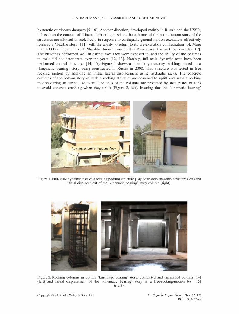
hysteretic or viscous dampers [5–10]. Another direction, developed mainly in Russia and the USSR,is based on the concept of ‘kinematic bearings’, where the columns of the entire bottom story of thestructures are allowed to rock freely in response to earthquake ground motion excitation, effectivelyforming a ‘flexible story’ [11] with the ability to return to its pre-excitation configuration [3]. Morethan 400 buildings with such ‘flexible stories’ were built in Russia over the past four decades [12].The buildings performed well in earthquakes they were exposed to, and the ability of the columnsto rock did not deteriorate over the years [12, 13]. Notably, full-scale dynamic tests have beenperformed on real structures [14, 15]. Figure 1 shows a three-story masonry building placed on a‘kinematic bearing’ story being constructed in Russia in 2008. This structure was tested in freerocking motion by applying an initial lateral displacement using hydraulic jacks. The concretecolumns of the bottom story of such a rocking structure are designed to uplift and sustain rockingmotion during an earthquake event. The ends of the columns are protected by steel plates or capsto avoid concrete crushing when they uplift (Figure 2, left). Insuring that the ‘kinematic bearing’
Figure 1. Full-scale dynamic tests of a rocking podium structure [14]: four-story masonry structure (left) andinitial displacement of the ‘kinematic bearing’ story column (right).
Figure 2. Rocking columns in bottom ‘kinematic bearing’ story: completed and unfinished column [14](left) and initial displacement of the ‘kinematic bearing’ story in a free-rocking-motion test [15]
(right).
J. A. BACHMANN, M. F. VASSILIOU AND B. STOJADINOVIĆ
Copyright © 2017 John Wiley & Sons, Ltd. Earthquake Engng Struct. Dyn. (2017)DOI: 10.1002/eqe

story does not collapse (overturn) in a design-basis earthquake and control of the forces in thesuperstructure is achieved by sizing the rocking columns (Figure 2, right). Design guidelines for suchrocking structures were presented in the early 1970s in Polyakov’s well-known textbook [3]. Hesuggested (i) that the superstructure on top of the ‘flexible story’ behave as a rigid body and (ii) thatthe dynamics of the ‘flexible’ first story (the ‘kinematic bearing’ ground floor) be described using anelastic fixed-base cantilever SDOF model. A similar modeling approach for rocking structures waslater suggested by [16].
The study presented in this paper is part of a broad effort undertaken at ETH Zurich to investigatethe dynamics of rigid and flexible rocking structures and provide guidelines for their seismic design.A class of rocking podium structures is defined first, followed by the formulation of the equations ofrocking motion of such structures. After conducting a dimensional analysis of the equations ofmotion, they are solved for analytical pulse and recorded ground motion excitation to investigatethe stability and maximum deformation demands and capacities of rocking podium structures. Thefindings indicate that rocking podium structures are stable under earthquake ground motionexcitation and that fairly simple design rules of thumb suggested by Polyakov [3] produceconservative designs.
2. ROCKING STRUCTURES
In 1963, Housner [17] proved that out of two geometrically similar blocks, the larger one is more stablewhen excited dynamically. Accordingly, ground motions with longer dominant periods have a largeroverturning potential. In displacement-based design terminology, larger blocks have a larger‘displacement capacity’.
The dynamic behavior of a simple, free-standing rigid rocking block (Figure 3, right) has beensystematically studied for more than five decades [18–23]. The behavior of deformable solitaryrocking oscillators has also been studied [24–32], to conclude that deformable rocking structures arealso remarkably stable when excited by earthquakes. If the ends of the columns are protected,energy dissipation during rocking motion happens instantaneously when the body impacts theground. Several different modeling approaches have been proposed [33–36] to describe thisphenomenon. The probabilistic treatment of the rocking problem [37–39] further confirms theremarkable stability of rocking structures.
In addition to remarkable stability, rocking structures return to their original, undeformed positionafter the ground motion excitation (if they do not overturn, i.e., collapse), without a residualdisplacement that inevitably occurs in yielding a fixed-base cantilever structure (Figure 3, left). Thisdynamic property of rocking structures contributes very significantly to improving their seismicperformance for downtime and repair cost performance objectives.
Figure 3. Comparison of force–drift ratio response curves: inelastic cantilever column (left), real andidealized behaviors (middle), and rigid rocking column (right).
DYNAMICS OF ROCKING PODIUM STRUCTURES
Copyright © 2017 John Wiley & Sons, Ltd. Earthquake Engng Struct. Dyn. (2017)DOI: 10.1002/eqe

These favorable dynamic properties, as well as the observation that modern and ancient structuresthat were unintentionally designed to rock behaved well during earthquakes, have motivatedengineers to try to use uplifting and rocking as a structural seismic response modification technique[40–44]. In these structures, uplifting at the interface between rocking structural elements works as amechanical fuse and limits the forces transmitted to the structure.
The restoring force–displacement behavior for rocking systems idealized as rigid is inherentlydifferent from that of a fixed-base SDOF cantilever system (Figure 3, left). Before uplift, the rigidrocking structure does not deform. After uplift, the restoring force in a rocking system decreases asthe lateral displacement increases (the system has a negative post-uplift stiffness), while the post-yield resistance of a fixed-base cantilever increases (at least initially, the system has a positive post-yield stiffness). The dynamics of the two systems is very different: Makris and Konstantinidis [45]have shown that approaches based on equivalent elastic SDOF models [16] are not applicable torocking structures and stated that the elastic response spectra should not be used to evaluate ordesign rocking structures. The lack of relatively simple rocking structure design models (as opposedto complex response simulation models) continues to deter wider use of rocking structures inearthquake engineering practice.
Rocking frame structures shown in Figure 4 are an important class of rocking structures. They havebeen proven to be more stable than solitary columns of the same size and slenderness as the columns ofthe frame [46–50]. Counterintuitively, such rocking frames become more stable as the weight of thecap beam increases [47]. Building [12, 51, 52] and bridge [1] structures based on the rocking frameconcept have already been constructed. The objectives of this paper are to present a dynamic modelfor analysis of the in-plane seismic response of rocking frames that carry a structure (a rockingpodium structure, Figure 5) and to investigate if the rule-of-thumb guidelines for seismic design ofsuch structures proposed by Polyakov [3] are adequate.
Figure 4. Dynamic model of a rocking frame. Initial position (left) and rocking position (right).
Figure 5. Dynamic model of a rocking podium structure. Initial position (left) and rocking position (right).
J. A. BACHMANN, M. F. VASSILIOU AND B. STOJADINOVIĆ
Copyright © 2017 John Wiley & Sons, Ltd. Earthquake Engng Struct. Dyn. (2017)DOI: 10.1002/eqe

3. DYNAMIC MODEL OF A ROCKING PODIUM STRUCTURE
The equation of in-plane motion for a rigid rectangular rocking column (Figure 3, right) withslenderness α and a semi-diagonal of length R is
€θ ¼ �p2� sin ± α� θ½ � þ €ugg
cos ± α� θ½ �� �
(1)
where
p ¼ffiffiffiffiffiffiffiffiffiffiffiffiffiffiffiffiffiffiffiffiffi3gð Þ= 4Rð Þ
p(2)
is the frequency parameter of the rocking column. The upper sign in front of α corresponds to apositive, and the lower sign to a negative rocking angle θ with respect to the defined coordinate system(Figure 3, right).
Makris and Vassiliou [46] extended the rocking model of a solitary rigid rectangular column to arocking frame comprising N rigid columns capped by a rigid beam (Figure 4, left). Uplift of thecolumns is not restrained, but their sliding on the rocking surface is precluded. The correspondingequation of motion becomes
€θ ¼ �p̂2� sin ± α� θ½ � þ €ugg
cos ± α� θ½ �� �
(3)
where the frequency parameter of the rocking frame is
p̂ ¼ffiffiffiffiffiffiffiffiffiffiffiffiffi1þ 2γ1þ 3γ
s�ffiffiffiffiffiffi3g4R
r(4)
and γ is the mass ratio of the mass of the cap beam divided by the mass of all N columns:
γ ¼ mb
Nmc(5)
Since the frequency parameter p̂ of the rocking frame is always smaller than the frequencyparameter of a solitary column p, the response (tilt angle θ) of the rocking frame to the sameground excitation üg is always smaller than the response of the solitary column. As the mass of thecap beam increases, the mass ratio γ increases and the frequency parameter p̂ decreases, leading toa conclusion that rocking frames become more stable as the cap beam becomes more massive.
The response of the rocking frame is equal to the response of an equivalent solitary column that isgeometrically similar to, yet larger than, the columns of the frame. The size of the equivalent solitaryrocking column is
R̂ ¼ 1þ 3γ1þ 2γ
R (6)
Even though most researchers have studied blocks of rectangular solid cross sections, the originalderivation by Housner [17] was developed for blocks of general geometry and mass distribution.Therefore, in order to account for rocking frame columns with non-rectangular shapes and/ordifferent mass distributions, in this paper, a mass eccentricity ratio λ is defined as
λ ¼ ICmcR2 (7)
where IC is the rotational inertia of the column around its center of mass C. Then, the rockingfrequency parameter of the rocking frame is equal to
DYNAMICS OF ROCKING PODIUM STRUCTURES
Copyright © 2017 John Wiley & Sons, Ltd. Earthquake Engng Struct. Dyn. (2017)DOI: 10.1002/eqe

ep ¼ffiffiffiffiffiffiffiffiffiffiffiffiffiffiffiffiffiffiffiffiffi1þ 2γ
1þ λþ 4γ
s�ffiffiffigR
r(8)
and the size of the equivalent solitary column is
eR ¼ 1þ λþ 4γ1þ λþ 2γ 1þ λð ÞR (9)
The equation of motion of the frame is still given by either Eq. (1) or (3), with the frequencyparameter now equal to ep.
The value of parameter λ for a solid solitary column with evenly distributed mass and with a uniformrectangular cross section is 1/3. For a column with mass mc and semi-diagonal R, factor λ couldtheoretically take values between 0 (mass concentrated in the center of mass C) and 1 (massdistributed at the outside edges of the block). Realistic values for λ are as follows:
• Rectangular column (solid/hollow (thin walled)): λ = 0.33/0.34• Circular column (solid/hollow (thin walled)): λ = 0.35/0.35• R/C column with steel end protectors (Figure 2, ds = 5/10 cm): λ = 0.38/0.40
For example, a rocking frame with common solid rectangular columns (λ = 1/3) of size R, and a veryheavy cap beam (γ→ ∞) the size of the equivalent solitary column eR is 1.50 times larger than the size ofthe frame column R, matching exactly the value derived in [46].
3.1. Rocking podium structure
A multi-story superstructure built on a rocking first story, akin to the one shown in Figure 2, is modeledas a rocking podium structure shown in Figure 5. The dynamics of the superstructure are assumed to beadequately represented by a SDOF cantilever system. Thus, the rocking frame model described earlieris extended by adding a deformable SDOF system fixed on top of the cap beam of the rocking podiumframe. The following assumptions are made:
• The response of the superstructure remains elastic.• The superstructure mass mt is lumped at the top and does not have any rotational inertia.• The overturning moment excreted by the superstructure on the podium cap beam is not largeenough to cause uplift of the cap beam (detachment of the beam from the columns).
• The contact surfaces at the bottom and the top of the columns of the rocking podium frame do notallow any sliding and stay intact throughout the rocking motion (there is no crushing or permanentdeformation of the contact surfaces).
• The rocking first story is assumed to be rigid.
The rocking podium structure is a two-degree-of-freedom system where the motion of the rockingframe cap beam with respect to the support is described by the displacement ub (equivalently, tiltangle θ) and the motion of the superstructure mass mt with respect to the cap beam is described bythe displacement ut. A superstructure mass ratio is defined as
η ¼ mt
mb(10)
Assuming that the weight of each story is roughly the same, η can be interpreted as the number ofstories above the rocking podium frame.
3.2. Equation of motion before uplift and uplift criterion
The SDOF system representing the multi-story structure on the rocking podium has a fixed-basenatural frequency ωs and a viscous damping ratio ζ s. Before uplift, the equation of motion of thesuperstructure on top of the rocking podium frame is
€ut þ 2ζ sωs _ut þ ω2s ut ¼ �€ug (11)
J. A. BACHMANN, M. F. VASSILIOU AND B. STOJADINOVIĆ
Copyright © 2017 John Wiley & Sons, Ltd. Earthquake Engng Struct. Dyn. (2017)DOI: 10.1002/eqe

The rocking podium frame does not move before uplift, removing its degree of freedom fromconsideration. The uplift criterion for the rocking podium frame with N free-standing columns (eachwith slenderness α) capped with a rigid beam is the same as for a solitary rigid column ofslenderness α:
€ug ¼ ± g tan α (12)
The presence of the superstructure on top of the cap beam modifies this uplift criterion. Figure 6(right) shows the forces acting on the rocking podium at incipient uplift (for θ < 0). The lateralforce Vs is the resulting shear force acting at the base of the SDOF oscillator.
Vs ¼ k ut þ c _ut ¼ mt� ω2s ut þ 2ζ sωs _ut
� �(13)
The principle of virtual work for a positive üg and a virtual rotation of �δθ at incipient uplift isapplied:
δθ� BNmcg � HNmc€ug� �þ δθ� 2Bmbg þ 2Bmtgð Þ � δθ�2Hmb€ug þ δθ�2HVs ¼ 0 (14)
Combining Eqs (13) and (14) yields
€ug� 2mb þ Nmcð Þ ¼ g tanα� 2mb þ 2mt þ Nmcð Þ þ ω2smtut þ 2ζ sωsmt _ut (15)
Then, the rocking podium frame uplift thresholds for both positive and negative groundaccelerations are
€ug ¼ ± g tanαþ 2γη2γþ 1
± g tan αþ ω2s ut þ 2ζ sωs _ut
� �(16)
For rigid superstructures where ω2s ut þ 2ζ sωs _ut
� �→� €ug and for light superstructures where η→ 0,
Eq. (16) resolves to Eq. (12).
3.3. Equations of motion after uplift
The Lagrangian formulation is used to derive the equations of motion of the two-degree-of-freedomrocking podium structure after uplift as follows:
L ¼ T � V (17)
Figure 6. Elastic oscillation of the rocking podium structure due to ground excitation before uplift (left) andinternal forces at incipient uplift in response to the ground motion excitation (right).
DYNAMICS OF ROCKING PODIUM STRUCTURES
Copyright © 2017 John Wiley & Sons, Ltd. Earthquake Engng Struct. Dyn. (2017)DOI: 10.1002/eqe

ddt
∂L∂ _qi
� ∂L∂qi
¼ Qqi(18)
where T is the kinetic energy stored in the system, V is the potential energy of the system, andQqiis the
non-conservative force acting along direction qi, derived from the virtual work W carried out by theforces in the system for a virtual displacement δqi.
The horizontal displacement and vertical displacement of the rigid cap beam (Figure 5) are
ub ¼ 2R� sin ± α½ � � sin ± α� θ½ �ð Þwb ¼ 2R� cos ± α� θ½ � � cos αð Þ (19)
The first and second derivatives with respect to time of Eq. (19) are
_ub ¼ 2R� _θ cos ± α� θ½ �€ub ¼ 2R� €θ cos ± α� θ½ � þ _θ2 sin ± α� θ½ �� � (20)
_wb ¼ 2R� _θ sin ± α� θ½ �€wb ¼ 2R� €θ sin ± α� θ½ � � _θ2 cos ± α� θ½ �� � (21)
The kinetic energy in the system is
T ¼ Tt þ Tb þ Tc ¼ 12mt� _u2t þ _w2
t
� �þ 12mb� 2R _θ� �2 þ 1
2Nmc� 1þ λð Þ� R _θ
� �2(22)
where ut and wt are the horizontal and vertical displacement of the top mass. Given that
_wt ¼ _wb (23)
Equation (22) yields
T ¼ 12mt� _u2t þ 4R2sin2 ± α� θ½ � _θ2� �þ 1
2mb� 2R _θ� �2 þ 1
2Nmc� 1þ λð Þ� R _θ
� �2(24)
The potential energy (both gravitational and elastic) of the system is
V ¼ 2Rg� mb þ mt þ N12mc
� �cos ± α� θ½ � þ 1
2mtω2
s � ut � ubð Þ2 þ mt€ugut
�2R€ug� mb þ N12mc
� �sin ± α� θ½ �
(25)
The virtual work performed by the damping force is
δW ¼ f D�δqi ¼ �c� _ut � _ubð Þ�δut ¼ �2ζ smtωs� _ut � _ubð Þ�δut (26)
Applying Eq. (18) to the degree of freedom of the superstructure, ut, yields
€ut þ 2ζ sωs� _ut � 2R� _θ cos ± α� θ½ �� �þ ω2s � ut � 2R� sin ± α½ � � sin ± α� θ½ �ð Þð Þ ¼ �€ug (27)
A comparison of Eqs (11) and (27) shows that the displacement demand of the ground motion isnow taken by both the rocking podium frame and the elastic superstructure. The equation of motionfor the other degree of freedom, the rocking angle θ of the rocking frame that supports thesuperstructure, is
J. A. BACHMANN, M. F. VASSILIOU AND B. STOJADINOVIĆ
Copyright © 2017 John Wiley & Sons, Ltd. Earthquake Engng Struct. Dyn. (2017)DOI: 10.1002/eqe

€θR� 1þ λþ 4γþ 4γηsin2 ± α� θ½ �� � ¼þ 2Rγη _θ2 sin 2 ± α� θ½ �ð Þ � g� 2γþ 2γηþ 1ð Þ sin ± α� θ½ � � €ug� 2γþ 1ð Þ cos ± α� θ½ �þ 2γηωs cos ± α� θ½ �� ωs� ut � 2R� sin ± α½ � � sin ± α� θ½ �ð Þð Þ þ 2ζ s� _ut � 2R� _θ cos ± α� θ½ �� �� � (28)
The equations present a similarity with several other problems of rocking–elasticity interaction[24, 28, 30, 53, 54].
3.4. Impacts and energy dissipation
The proposed dynamic model of a rocking podium structure has two degrees of freedom. Thus, twoequations are needed to determine the post-impact condition and, thereby, the energy dissipated atimpact. The model proposed by Housner [17] presumes that rocking column impacts areinstantaneous and that the contact forces between the rocking column and the rocking surfaces areconcentrated at the pivot points. Therefore, at the moment of impact, the pivot point instantaneouslymoves to the other edge of the column. This assumption has been previously used to calculate thecoefficient of restitution in several rocking systems [46, 50, 55]. The aforementioned assumptionresults in Conservation of Angular Momentum (CoAM) for each column of the rocking podiumframe during impact. Moreover, it is assumed that the elastic deformation of the superstructure issmall compared with its size (height hc), so CoAM is applied in the undeformed configuration of therocking podium structure (Figure 5, left). This yields the first equation. The second equation comesfrom the assumption that the relative horizontal velocity between the superstructure mass and thecap beam does not change during impact.
Using the aforementioned assumptions, one can derive Eq. (29) for the coefficient of restitution andEq. (30) for the horizontal velocity of the superstructure mass after impact:
c ¼_θ2after_θ2before
¼ 1� 2sin2α� 1þ 4γ� 1þ ηð Þ1þ λþ 4γ� 1þ ηð Þ
� �2(29)
_ut;after ¼ _ut;before � 2R cos α� _θbefore� 1�ffiffiffic
p� �(30)
Equation (29) can be compared with the expressions for the coefficient of restitution of other,simpler, rocking systems. With η = γ = 0, for example, it yields exactly what Housner proposed forhis rigid block, and with η = 0, its solution is equal to the expression of Makris and Vassiliou [46]for a rocking frame.
Different impact assumptions have also been proposed for deformable rocking structures [24, 27,28, 53], but their thorough investigation is beyond the scope of this study.
3.5. Frequency in the uplifted state
As has been shown both analytically [28, 30, 31, 56] and experimentally [25, 32, 34, 57], the naturalfrequency of an uplifted structure ωs,u is larger than the fixed-base frequency ωs of the same structure.This supports the assumption of a ‘rigid-body superstructure’ found in [3]. The uplifted frequency canbe computed through eigenfrequency analysis of the rocking podium structure:
K � ω2s;uM
¼ 0 (31)
where K is the stiffness matrix and M is the mass matrix of the rocking podium structure. In thepresence of damping, the aforementioned equation needs to be correct only if damping satisfies theCaughey–O’Kelly condition [32], which is not the case. However, since the superstructure remainselastic, the energy dissipated through its motion (its damping) is expected to be relatively smallcompared with the energy dissipated by the rocking of the podium frame, and, therefore, Eq. (31) isexpected to give a good approximation of the uplifted frequencies. This was experimentallyconfirmed for other elastic uplifting systems [32, 34, 57].
DYNAMICS OF ROCKING PODIUM STRUCTURES
Copyright © 2017 John Wiley & Sons, Ltd. Earthquake Engng Struct. Dyn. (2017)DOI: 10.1002/eqe

Linearizing the equations of motion of the rocking podium structure (Eqs. (27) and (28)) andneglecting gravity yield the mass and stiffness matrices of the system:
M ¼ R� 1þ λþ 4γþ 4γη sin2α �
0
0 1
" #; K ¼ 4Rγηω2
s cos2α �2γηω2
s cos α
�2Rω2s cos α ω2
s
" #(32)
Solving the eigenvalue problem (Eq. (31)) gives
ω4s;u� 1þ λþ 4γþ 4γη sin2α� �� ω2
s;uω2s � 1þ λþ 4γþ 4γηð Þ ¼ 0 (33)
The eigenfrequency analysis reveals the two distinct mode shapes of the uplifted rocking podiumstructure. The first one is a rotation of the podium frame columns with a natural frequency of 0 Hz,a rigid body mode. The second one is the vibration of the elastic SDOF system when the rockingpodium frame is uplifted (Figure 5, right). In this uplifted state, the natural eigenfrequency ωs,u ofthe SDOF system is
ωs;u ¼ffiffiffiffiffiffiffiffiffiffiffiffiffiffiffiffiffiffiffiffiffiffiffiffiffiffiffiffiffiffiffiffiffiffiffiffiffiffiffiffiffiffiffiffiffiffiffiffi
1þ λþ 4γ� 1þ ηð Þ1þ λþ 4γ� 1þ η sin2α
� �s�ωs (34)
Clearly, the natural frequency of the uplifted SDOF systemωs,u is larger than its fixed-base frequencyωs. For heavy superstructures (η→∞) (i.e., large number of stories), the amplification factor simplifies to1/sin(α), which coincides with the solution of Yim and Chopra [56] for structures with foundation uplift.
Figure 7 (left) plots the superstructure vibration frequency amplification factor for different valuesagainst the superstructure mass ratio for the three superstructure mass ratio values, effectivelyrepresenting the number of stories above the rocking podium frame. It can be seen that theeigenfrequencies of superstructures with more stories experience larger amplification when thepodium is uplifted. However, assuming that the fixed-base natural frequency of a building is given bythe empirical relation fn = 10 Hz/ns (where ns is the number of stories), one can prove that theuplifted frequency of the superstructure decreases with increasing number of stories. Since a planarmodel is used to represent the in-plane behavior of a 3D podium structure, the cap beam representsthe mass of a whole slab. Typically, this slab is much heavier than the total weight of the columns, soγ is expected to have a large value. Therefore, it is reasonable to assume that the eigenfrequencies ofthe superstructure when the podium is in the uplifted state are given by the limit of Eq. (34) as γ → ∞:
ωs;u ¼ffiffiffiffiffiffiffiffiffiffiffiffiffiffiffiffiffiffiffiffiffiffi
1þ η1þ η sin2α
s�ωs (35)
Figure 7 (right) plots Eq. (35) for different values of column slenderness α, assuming γ = 10.
Figure 7. Amplification factor for the natural frequency ωs of the elastic superstructure on a rocking podiumframe in the uplifted (rocking) state: variation with respect to the beam mass ratio γ (left) and variation with
respect to the superstructure mass ratio η, given γ = 10 (right).
J. A. BACHMANN, M. F. VASSILIOU AND B. STOJADINOVIĆ
Copyright © 2017 John Wiley & Sons, Ltd. Earthquake Engng Struct. Dyn. (2017)DOI: 10.1002/eqe

3.6. Damping in the uplifted state
As in [28, 30, 32, 56], the assumption of viscous damping of the superstructure leads to a damping ratioin the uplifted state equal to
ζ s;u ¼ffiffiffiffiffiffiffiffiffiffiffiffiffiffiffiffiffiffiffiffiffiffiffiffiffiffiffiffiffiffiffiffiffiffiffiffiffiffiffiffiffiffiffiffiffiffiffiffi
1þ λþ 4γ� 1þ ηð Þ1þ λþ 4γ� 1þ η sin2α
� �s�ζ s ¼ Sr�ζ s (36)
However, the results of experiments [34] show that uplifting of a deformable rocking column maynot affect its damping. Therefore, it is reasonable to assume that the forces representing energydissipation in the equation of motion of the superstructure are not proportional to the elastic velocityof the superstructure. However, since damping in the superstructure is expected to be small, [34]suggests to use viscous damping equal to ζ s/Sr so that damping in the uplifted (amplified) state isequal to ζ s.
4. DIMENSIONAL ANALYSIS OF THE ROCKING PODIUM STRUCTURE MODEL
Strong ground motions often contain a distinguishable acceleration pulse, which is responsible formost of the inelastic deformation of fixed-base structures [58–60]. Physically realizable groundmotion analytical pulses can qualitatively describe the impulsive character of near-fault groundmotions. For a particular pulse shape, two parameters are needed to describe such pulses. Theacceleration amplitude, ap, and dominant cyclic frequency, ωp, of the pulse, or the velocityamplitude, vp, and dominant cyclic frequency, ωp, have been previously used [59]. This sectionexamines the response of the rocking podium structure model shown in Figure 5 to an idealizedacceleration pulse characterized by its amplitude, ap, and dominant cyclic frequency, ωp [61]. Thetilt angle response is a function of 10 variables:
θ ¼ f α;R; g;ωp; ap; η; γ;ωs; ζ s; t� �
(37)
involving two fundamental dimensions. According to Buckingham’s Π theorem [62], the response canbe described by 10 � 3 = 7 dimensionless parameters. Combining the Π theorem with orientationalanalysis arguments [63] and taking into account that tan(α) is bijective for 0 < α < π/2, the problemcan be described as
θα¼ φ α;
ωp
p;
apg tanα
; η; γ;ωs
p; ζ s; τ
� �(38)
where τ = pt and p is defined by Eq. (2).
4.1. Range of interest of the dimensionless parameters
• Column slenderness tan(α): Since tan(α) controls the superstructure design forces, in order for therocking podium structure to work as a useful seismic isolation system, α cannot be excessivelylarge. Typically, slenderness values tan(α) < 0.3 are meaningful.
• Size-frequency parameter ωp/p: Ideal candidates for rocking isolation, such as tall bridges andchimneys, can have a height reaching several tens of meters. However, in the model under study,typical rocking podium columns are expected to have a height of no more than 6 m. A value of ωp/p = 8 corresponds to a pulse period of 0.5 s for a 6-m-tall column. Therefore, values of ωp/p < 8will be examined.
• Dimensionless masses η and γ: For superstructure floors of equal mass, η corresponds to thenumber of floors. Superstructures with up to 10 floors (for rocking spectra) and up to five floors(for time history analysis) are analyzed. As previously explained, γ is expected to be large as itrepresents a slab-to-columns mass ratio. Figure 7 (left) shows that the frequency amplificationratio has already saturated for γ = 10, so γ is set to equal to 10.
DYNAMICS OF ROCKING PODIUM STRUCTURES
Copyright © 2017 John Wiley & Sons, Ltd. Earthquake Engng Struct. Dyn. (2017)DOI: 10.1002/eqe

• Dimensionless superstructure stiffness ωs/p: A lower bound for ωs/p is derived by minimizing ωs
and maximizing p (i.e., minimizing rocking column height). Therefore, a lower bound of ωs/p isobtained by assuming a 10-story superstructure placed on a 3-m-tall rocking podium. Then, thefundamental period of the superstructure is on the order of 1 s and ωs/p ≈ 3. For the resultspresented in this paper, a lower bound of ωs/p = 3 is chosen.
• Superstructure damping ratio: The superstructure is intended to remain elastic during its responseto design-basis excitation. Therefore, its fixed-base structural damping is expected to be no largerthan 0.01. According to Section 3.6, ζ s = 0.01/Sr is used. This way, the uplifted damping will beconstant and equal to 0.01.
5. RESPONSE OF THE ROCKING PODIUM STRUCTURE TO ANALYTICAL PULSEGROUND MOTIONS
The second derivative of the Gaussian distribution, exp(�t2/2), known in the seismological literature asthe symmetric Ricker wavelet [64],
€ug tð Þ ¼ ap 1� 2π2t2
T 2p
!e�1
22π2 t2
T2p (39)
plotted in Figure 8 (right), has often been used to approximate the pulses contained in pulse-likeground motions. The value of the pulse period Tp = 2π/ωp maximizes the Fourier spectrum of thesymmetric Ricker wavelet. Similarly, Eq. (40) is the scaled third derivative of the Gaussiandistribution exp(�t2/2), also referred to as the antisymmetric Ricker wavelet (Figure 8, left), inwhich factor β is equal to 1.3801 to enforce that the function maximum is equal to ap.
€ug tð Þ ¼ apβ
4π2t2
3T2p
� 3
!2πtffiffiffi3
pTp
e�1
24π2 t2
3T2p (40)
Figures 9 and 10 show the maximum rocking angle response spectra for antisymmetric andsymmetric Ricker wavelet excitations. From left to right, the weight of the superstructure (i.e., thenumber of stories), defined by Eq. (10), is increased (η ∈ {1, 5, 10}). From top to bottom, thenatural period Ts of the superstructure SDOF model is increased from 0 s (rigid) to 0.95 s(deformable) (ωs/p ∈ {∞, 30, 6, 3}). The podium cap beam-to-column mass ratio is chosen as γ = 10as it was found that its further increase does not influence the response (Figure 7, left). The columnslenderness used to compute the rocking spectra is tan(α) = 0.15. Results of analyses for otherslenderness values, not presented here because of space limits, show that the rocking podium spectraare not sensitive to this parameter. The mass eccentricity factor λ is set to 1/3 (uniformly distributedcolumn mass). Although a new size parameter p̃, that also takes γ into account, was introduced withEq. (8), the lower x-axes of the spectra show the value of the pulse natural frequency ωp normalizedby p, which corresponds to the frequency parameter of a column with evenly distributed mass andsemi-diagonal R, defined by Eq. (2). To give a sense of the magnitude of the non-dimensional termωp/p, the pulse period, Tp, that corresponds to p = 2.2 s�1 (column with 2H = 3 m) is plotted on thetop horizontal axis. In order to test the second design guideline of Polyakov [3], that is, the rockingframe should be treated as a very flexible elastic structure; the spectra in Figures 9 and 10 also plot
Figure 8. Analytical pulses: antisymmetric Ricker wavelet (left) and symmetric Ricker wavelet (right).
J. A. BACHMANN, M. F. VASSILIOU AND B. STOJADINOVIĆ
Copyright © 2017 John Wiley & Sons, Ltd. Earthquake Engng Struct. Dyn. (2017)DOI: 10.1002/eqe

(white dashed lines) the pulse acceleration that would cause a displacement of the system (measured atthe top of the rocking columns) equal to the column total width (2B) and would, therefore, causecollapse. This design guideline is consistent to what [65–67] propose.
Figure 11 plots the minimum overturning acceleration spectra for both symmetric and antisymmetricRicker wavelet excitation. It shows that the interaction between the rocking podium frame and theelastic superstructure follows similar trends as the ones observed in [28, 30].
1. For low values of ωp/p (small height of the rocking podium frame or low-frequency pulses), thedeformability of the superstructure has a detrimental effect on the stability of the system, whilethe opposite holds for high values of ωp/p.
Figure 9. Rocking spectra (maximum base rotation, θ/α) of a rocking podium structure with γ = 10 anddifferent values of ωs/p (∞, 30, 6, 3) and η (1, 5, 10) subjected to an antisymmetric Ricker wavelet. The
white dashed line indicates Polyakov’s overturning acceleration.
DYNAMICS OF ROCKING PODIUM STRUCTURES
Copyright © 2017 John Wiley & Sons, Ltd. Earthquake Engng Struct. Dyn. (2017)DOI: 10.1002/eqe

2. For low values of ωp/p, the deformability of the superstructure clearly decreases the accelerationneeded to cause uplift.
3. The effects of the superstructure deformability become negligible for ωs/p > 6. For 3-m-tallcolumns, this value of ωs/p corresponds to a structural period, Ts, equal to 0.48 s.
4. The weight of the superstructure has only a marginal influence on the system stability.
Based on these findings, the first Polyakov [3] guideline (to treat the superstructure of rockingpodium structures as a rigid body) is reasonable, at least for superstructures with natural periodsshorter than 0.48 s (for a rocking column height equal to 3 m).
For values of ωp/p < 1.8, the second Polyakov guideline (modeling the rocking story as a veryflexible elastic oscillator) is conservative. However, for larger values of ωp/p (corresponding to pulse
Figure 10. Rocking spectra (maximum base rotation, θ/α) of a rocking podium structure with γ = 10 anddifferent values of ωs/p (∞, 30, 6, 3) and η (1, 5, 10) subjected to a symmetric Ricker wavelet. The white
dashed line indicates Polyakov’s overturning acceleration.
J. A. BACHMANN, M. F. VASSILIOU AND B. STOJADINOVIĆ
Copyright © 2017 John Wiley & Sons, Ltd. Earthquake Engng Struct. Dyn. (2017)DOI: 10.1002/eqe

periods smaller than about 1.6 s for 3-m-tall columns of the rocking frame), analytical pulse analysissuggests that this assumption become non-conservative and should clearly be avoided.
6. RESPONSE OF THE ROCKING PODIUM STRUCTURE TO RECORDED GROUNDMOTIONS
Recorded ground motions might or might not contain acceleration pulses. Even in the case of pulse-like ground motions, the pulse itself cannot entirely describe the overturning potential of the groundmotion [38]. Therefore, the analysis presented in the previous section provides only qualitativeconclusions. In order to further explore the stability of rocking podium structures and to furthercheck the validity of the design rules of thumb proposed by Polyakov [3], the model presented inthis paper is excited with recorded ground motions.
A model with a 3-m-tall rocking frame that supports either a one-story (η = 1, Ts = 0.1 s) or five-story (η = 5, Ts = 0.5 s) superstructure. In order to have different displacement capacities of therocking columns, models with column slenderness of 0.15 (used for Ricker pulse analyses) as wellas 0.10 and 0.20 are analyzed. According to Polyakov’s design guidelines [3], a rocking column isstable as long as the maximum of ground motion elastic displacement spectrum, SDmax, is smallerthan the width of the column 2B (e.g., 2B = 0.60 m for tan(α) = 0.20). A viscous damping ratio of2% was used to compute the ground motion elastic displacement spectra. This should not beconfused with the superstructure damping. It is the viscous damping of Polyakov’s equivalent linearsystem that is intended to approximate the damping of the rocking story.
Tables I and II show the recorded ground motions from the Next Generation Attenuation (NGA)[68] database that were used to investigate the response of rocking podium structures for pulse-like(group A) and non-pulse-like (group B) ground motions. The records are chosen such that SDmax
values, shown in the last column of the tables, vary sufficiently to cover different displacementcapacities (2B either 0.30, 0.45, or 0.60 m) of the podium structure columns.
In general, the maximum spectral displacement approach proposed by Polyakov [3] leads to aconservative design. Figure 12 compares the maximum displacement at the top of the rockingpodium columns ubmax computed in the ground motion response history analyses using the proposedrocking podium structure model to the maximum elastic spectral displacement for each of the 126conducted analyses, both normalized by 2B. According to [3], SDmax > 2B corresponds tooverturning. Points above the ubmax/2B = 1 line correspond to overturning according to the rockingpodium model, while points right of the SDmax/2B = 1 line correspond to overturning according tothe maximum elastic spectral displacement. For points below the diagonal, the SDmax approach isconservative, while the opposite holds for points above the diagonal. There are many groundmotions for which the SDmax approach predicts overturning while the rocking podium structure
Figure 11. Overturning spectra for a rocking podium structure subjected to Ricker wavelets: antisymmetricRicker (left) and symmetric Ricker (right).
DYNAMICS OF ROCKING PODIUM STRUCTURES
Copyright © 2017 John Wiley & Sons, Ltd. Earthquake Engng Struct. Dyn. (2017)DOI: 10.1002/eqe

model does not. However, out of 126 response history analyses, there were only two false-negative(i.e., unconservative) overturning predictions. The transverse-direction record of the 1986 SanSalvador earthquake (no. A3) overturns both rocking podium buildings (η = 1 and η = 5) withcolumns with a slenderness of tan(α) = 0.15 in a response history analysis. However, Polyakov’sSDmax/2B = 0.36 m/0.45 m = 0.80 < 1 criterion indicates the buildings should survive thisearthquake ground motion.
Table I. Pulse-like ground motions used for the rocking podium structure seismic response analysis.
No. Earthquake Year StationNGA filename PGA (g) SDmax (m)
A1 Parkfield 1966 C #2/065 00029L 0.48 0.46A2 San Fernando 1971 Pacoima Dam/164 00077L 1.23 1.06A3 San Salvador 1986 Geotech Invest Center/180 00568T 0.48 0.36A4 Whittier Narrows 1987 LB-Orange Ave/010 00645L 0.26 0.14A5 Spitak 1988 Gukasian/000 00730L 0.20 0.31A6 Loma Prieta 1989 Oakland, outer Harbor Wharf/000 00783L 0.29 0.33A7 Erzincan 1992 Erzincan/NS 00821L 0.52 0.94A8 Erzincan 1992 Erzincan/EW 00821T 0.50 0.85A9 Landers 1992 Yermo Fire Station/270 00900L 0.24 1.19A10 Landers 1992 Yermo Fire Station/360 00900T 0.15 0.70A11 Northridge 1994 Jensen Filter Plant Gen BLDG/022 00983L 0.56 1.25A12 Kobe 1995 Takarazuka/000 01119L 0.69 0.77A13 Kobe 1995 Takarazuka/090 01119T 0.69 0.55
Table II. Non-pulse-like ground motions used for the rocking podium structure seismic response analysis.
No. Earthquake Year StationNGA filename PGA (g) SDmax (m)
B1 Imperial Valley 1940 Imperial Valley/180 00006L 0.31 0.37B2 Imperial Valley 1940 Imperial Valley/270 00006T 0.21 0.64B3 San Fernando 1971 Pacoima Dam/254 00077T 1.16 0.36B4 San Salvador 1986 Geotech Invest Center/090 00568L 0.87 0.46B5 Whittier Narrows 1987 LB-Orange Ave/280 00645T 0.15 0.07B6 Spitak 1988 Gukasian/090 00730T 0.18 0.18B7 Loma Prieta 1989 Oakland, outer Harbor Wharf/270 00783T 0.27 0.46B8 Northridge 1994 Jensen Filter Plant Gen BLDG/292 00983T 1.04 0.70
Figure 12. Results of earthquake ground motion response history analyses: maximum top columndisplacement ubmax versus maximum elastic spectral displacement SDmax.
J. A. BACHMANN, M. F. VASSILIOU AND B. STOJADINOVIĆ
Copyright © 2017 John Wiley & Sons, Ltd. Earthquake Engng Struct. Dyn. (2017)DOI: 10.1002/eqe
In contrast to the responses to analytical pulse ground motions, the responses of the rocking podiumstructures to recorded ground motions are more sensitive to the column slenderness parameter. It seemsthat the high-frequency incoherent component of the ground motion is oftentimes able to inducecolumn uplift and initiate the rocking motion earlier. This observation parallels the conclusion forelastic rocking structures with similar column sizes [27].
The ground motion analysis results also reveal that the SDmax approach gives conservative results in alarger range of pulse frequencies than the analytical pulse analysis shows. Namely, analytical pulseanalysis predicts that the SDmax approach is unconservative for ωp/p > 1.8 (i.e., for 3-m-tall rockingpodium frame columns, the approach is unconservative for pulses with pulse period Tp < 1.6 s)(Figure 11). However, the Erzincan (A7) and the Northridge (A11) pulses have frequencies on theorder of 0.9 and 0.5 s, respectively, and still, the maximum elastic spectral displacement approach isconservative. It seems that, for the ground motions used, the incoherent high-frequency component ofthe groundmotion increased SDmaxmore than it increased the overturning potential of the groundmotion.
7. CONCLUSIONS
Rocking podium structures comprise a superstructure anchored on top of a rigid slab supported by free-standing columns that can uplift and undergo rocking motion in response to sufficiently strong groundmotion excitation. A dynamic model that describes the in-plane seismic response of such structures(Figure 5) was derived and presented in this paper. This model was used to analyze the seismicresponse of a wide range of rocking podium structures to analytical pulse and recorded groundmotion excitations. The computed responses indicate that rocking podium structures remain stableunder ground motion excitation and that the rule-of-thumb guidelines of Polyakov [3] areconservative in most of the cases examined.
The equivalent seismic forces acting on the superstructure are controlled by the dimensions of therocking podium columns. Determining the magnitude of these forces requires more accurate modelsof the rocking podium and the superstructure and is the focus of ongoing research.
REFERENCES
1. Beck JL, Skinner RI. The seismic response of a reinforced concrete bridge pier designed to step. EarthquakeEngineering and Structural Dynamics 1973, 2(4):343–358. https://doi.org/10.1002/eqe.4290020405.
2. Sharpe RD, Skinner RI. The seismic design of an industrial chimney with rocking base. Bulletin of the New ZealandNational Society for Earthquake Engineering 1983, 16(2):98–106.
3. Polyakov SV. Design of Earthquake Resistant Structures. English tr. Moscow: MIR Publishers; 1974.4. Huckelbridge A, Clough R. Earthquake Simulation Tests of a Nine Story Steel Frame with Columns Allowed to
Uplift. 1977.5. Ricles JM, Sause R, Garlock MM, Zhao C. Posttensioned seismic-resistant connections for steel frames. Journal of
Structural Engineering 2001, 127(2):113–121 https://doi.org/10.1061/(ASCE)0733-9445(2001)127:2(113).6. Priestley M, Sritharan S, Conley J, Pampanin S. Preliminary Results and Conclusions from the PRESSS Five-story
Precast Concrete Test Building. 1999.7. Liu R, Palermo A. Low damage design and seismic isolation: what’s the difference? 2015 NZSEE Conference, 2015.8. Vassiliou MF, Makris N. Dynamics of the vertically restrained rocking column. Journal of Engineering Mechanics
2015, 141(12): 4015049. https://doi.org/10.1061/(ASCE)EM.1943-7889.0000953.9. Makris N, Vassiliou MF. Dynamics of the rocking frame with vertical restrainers. Journal of Structural Engineering
2015, 141(10): 4014245. https://doi.org/10.1061/(ASCE)ST.1943-541X.0001231.10. Giouvanidis AI, Dimitrakopoulos EG. Seismic performance of rocking frames with flag-shaped hysteretic behavior.
Journal of Engineering Mechanics 2016; accepted 5 OCT.11. Zeris C. Seismic response of rocking oscillators on a soft story: elastic response. Journal of Structural Engineering
2015, 141(8): 4014196. https://doi.org/10.1061/(ASCE)ST.1943-541X.0001157.12. Cherepinskiy Y. Seismic isolation of buildings with application of the kinematics bases. 13th World Conference on
Earthquake Engineering, 2004.13. Uzdin AM, Doronin FA, Davydova GV, Avidon GE, Karlina EA. Performance analysis of seismic-insulating
elements with negative stiffness. Soil Mechanics and Foundation Engineering 2009, 46(3):15–21.14. Semenov S, Kurzanov A. Kinematic base isolation systems 2011. https://www.youtube.com/watch?
v=Tqr0k4Dw2FM [accessed March 1, 2016].15. Semenov S. Сейсмоизоляция protection against earthquake 2015. https://www.youtube.com/watch?
v=sZ5KCX2wMd0 [accessed March 1, 2016].
DYNAMICS OF ROCKING PODIUM STRUCTURES
Copyright © 2017 John Wiley & Sons, Ltd. Earthquake Engng Struct. Dyn. (2017)DOI: 10.1002/eqe

16. Priestley M, Evison R, Carr A. Seismic response of structures free to rock on their foundations. Bulletin of the NewZealand National 1978, 141–150.
17. Housner GW. The behavior of inverted pendulum structures during earthquakes. Bulletin of the SeismologicalSociety of America 1963, 53(2):403–417.
18. Dimitrakopoulos EG, DeJong MJ. Overturning of retrofitted rocking structures under pulse-type excitations. Journalof Engineering Mechanics 2012, 138(8):963–972. https://doi.org/10.1061/(ASCE)EM.1943-7889.0000410.
19. Yim CS, Chopra AK, Penzien J. Rocking response of rigid blocks to earthquakes. Earthquake Engineering andStructural Dynamics 1980, 8(6):565–587. https://doi.org/10.1002/eqe.4290080606.
20. Psycharis IN, Jennings PC. Rocking of slender rigid bodies allowed to uplift. Earthquake Engineering and StructuralDynamics 1983, 11(1):57–76. https://doi.org/10.1002/eqe.4290110106.
21. Zhang J, Makris N. Rocking response of free-standing blocks under cycloidal pulses. Journal of EngineeringMechanics 2001, 127(5):473–483. https://doi.org/10.1061/(ASCE)0733-9399(2001)127:5(473).
22. Makris N, Vassiliou MF. Sizing the slenderness of free-standing rocking columns to withstand earthquake shaking.Archive of Applied Mechanics 2012, 82(10–11):1497–1511. https://doi.org/10.1007/s00419-012-0681-x.
23. Dimitrakopoulos EG, Fung EDW. Closed-form rocking overturning conditions for a family of pulse ground motions.Proceedings of the Royal Society A, 2016.
24. Oliveto G, Caliò I, Greco A. Large displacement behaviour of a structural model with foundation uplift underimpulsive and earthquake excitations. Earthquake Engineering and Structural Dynamics 2003, 32(3):369–393.https://doi.org/10.1002/eqe.229.
25. Ma QTM. The Mechanics of Rocking Structures Subjected to Ground Motion. 2010.26. Vassiliou MF, Mackie KR, Stojadinović B. Dynamic response analysis of solitary flexible rocking bodies: modeling
and behavior under pulse-like ground excitation. Earthquake Engineering and Structural Dynamics 2014,43(10):1463–1481. https://doi.org/10.1002/eqe.2406.
27. Acikgoz S, DeJong MJ. The rocking response of large flexible structures to earthquakes. Bulletin of EarthquakeEngineering 2014, 12(2):875–908. https://doi.org/10.1007/s10518-013-9538-0.
28. Vassiliou MF, Truniger RE, Stojadinović B. An analytical model of a deformable cantilever structure rocking on arigid surface: development and verification. Earthquake Engineering and Structural Dynamics 2015, 44(13).https://doi.org/10.1002/eqe.2608.
29. Wiebe L, Christopoulos C. A cantilever beam analogy for quantifying higher mode effects in multistorey buildings.Earthquake Engineering and Structural Dynamics 2015, 44(11):1697–1716.
30. Acikgoz S, DeJong MJ. The interaction of elasticity and rocking in flexible structures allowed to uplift. EarthquakeEngineering and Structural Dynamics 2012, 41(11):1–18. https://doi.org/10.1002/eqe.2181.
31. Acikgoz S, Dejong M. An investigation of the dynamics of rocking isolation for earthquake-resilient design.ECCOMAS Congress 2016: 7th European Congress on Computational Methods in Applied Sciences andEngineering, 2016.
32. Acikgoz S, DeJong MJ. Analytical modelling of multi-mass flexible rocking structures. Earthquake Engineering andStructural Dynamics 2016, 41(11):1549–1568 https://doi.org/10.1002/eqe.2735.
33. Peña F, Prieto F, Lourenço PB, Campos Costa A, Lemos JV. On the dynamics of rocking motion of single rigid-block structures. Earthquake Engineering and Structural Dynamics 2007, 36(15):2383–2399. https://doi.org/10.1002/eqe.739.
34. Truniger RE, Vassiliou MF, Stojadinović B. An analytical model of a deformable cantilever structure rocking on arigid surface: experimental validation. Earthquake Engineering and Structural Dynamics 2015, 44(13). https://doi.org/10.1002/eqe.2609.
35. Bachmann JA, Bloechlinger P, Wellauer M, Vassiliou MF, Stojadinovic B. Experimental investigation of the seismicresponse of a column rocking and rolling on a concave base. ECCOMAS Congress 2016: 7th European Congress onComputational Methods in Applied Sciences and Engineering, Heraklion: 2016.
36. Giouvanidis AI, Dimitrakopoulos EG. Nonsmooth dynamic analysis of sticking impacts in rocking structures.Bulletin of Earthquake Engineering 2017, 15(5):2273–2304. https://doi.org/10.1007/s10518-016-0068-4.
37. Psycharis IN, Fragiadakis M, Stefanou I. Seismic reliability assessment of classical columns subjected to near-faultground motions. Earthquake Engineering and Structural Dynamics 2013, 42(14):n/a–n/a https://doi.org/10.1002/eqe.2312.
38. Dimitrakopoulos EG, Paraskeva TS. Dimensionless fragility curves for rocking response to near-faultexcitations. Earthquake Engineering and Structural Dynamics 2015, 44(12):2015–2033. https://doi.org/10.1002/eqe.2571.
39. Bakhtiary E, Gardoni P. Probabilistic seismic demand model and fragility estimates for rocking symmetric blocks.Engineering Structures 2016, 114:25–34. https://doi.org/10.1016/j.engstruct.2016.01.050.
40. Mander JB, Cheng CT. Seismic resistance of bridge piers based on damage avoidance design. 1997.41. Sakai J, Mahin SA. Analytical Investigations of New Methods for Reducing Residual Displacements of Reinforced
Concrete Bridge Columns. Pacific Earthquake Engineering Research Center: Berkeley, CA, 2004.42. Wacker JM, Hieber DG, Stanton JF, Eberhard MO. Design of precast concrete piers for rapid bridge construction in
seismic regions. Research in Reproduction 2005.43. Cheng CT. Shaking table tests of a self-centering designed bridge substructure. Engineering Structures 2008,
30(12):3426–3433.44. Kokkali P, Abdoun T, Anastasopoulos I. Centrifuge modeling of rocking foundations on improved soil. Journal of
Geotechnical and Geoenvironmental Engineering 2015, 141(10): 4015041.
J. A. BACHMANN, M. F. VASSILIOU AND B. STOJADINOVIĆ
Copyright © 2017 John Wiley & Sons, Ltd. Earthquake Engng Struct. Dyn. (2017)DOI: 10.1002/eqe

45. Makris N, Konstantinidis D. The rocking spectrum and the limitations of practical design methodologies. EarthquakeEngineering and Structural Dynamics 2003, 32(2):265–289. https://doi.org/10.1002/eqe.223.
46. Makris N, Vassiliou MF. Planar rocking response and stability analysis of an array of free-standing columns cappedwith a freely supported rigid beam. Earthquake Engineering and Structural Dynamics 2013, 42(3):431–449. https://doi.org/10.1002/eqe.2222.
47. Makris N, Vassiliou MF. Are some top-heavy structures more stable? Journal of Structural Engineering 2014,140(5): 6014001. https://doi.org/10.1061/(ASCE)ST.1943-541X.0000933.
48. Papaloizou L, Komodromos P. Planar investigation of the seismic response of ancient columns and colonnades withepistyles using a custom-made software. Soil Dynamics and Earthquake Engineering 2009, 29(11–12):1437–1454.https://doi.org/10.1016/j.soildyn.2009.06.001.
49. Vassiliou MF, Mackie KR, Stojadinović B. A finite element model for seismic response analysis of deformablerocking frames. Earthquake Engineering and Structural Dynamics 2016; https://doi.org/10.1002/eqe.2799.
50. Dimitrakopoulos EG, Giouvanidis AI. Seismic response analysis of the planar rocking frame. Journal of EngineeringMechanics 2015, 141(7): 4015003. https://doi.org/10.1061/(ASCE)EM.1943-7889.0000939.
51. Eisenberg JM, Smirnov VI, Bubis AA. Recent developments in seismic isolation and energy dissipation in Russia.14th World Conference on Earthquake Engineering, 2008.
52. Eisenberg JM, Smirnov VI. Building seismic isolation in Russia without rubber and with rubber. ISET GoldenJubilee Symposium, 2012.
53. Psycharis IN. Effect of base uplift on dynamic response of SDOF structures. Journal of Structural Engineering 1991,117(3):733–754. https://doi.org/10.1061/(ASCE)0733-9445(1991)117:3(733).
54. Simoneschi G, de Leo AM, Di Egidio A. Effectiveness of oscillating mass damper system in the protection of rigidblocks under impulsive excitation. Engineering Structures 2017, 137:285–295.
55. Makris N, Vassiliou MF. Rocking response and stability analysis of an array of free-standing columns capped with afree-standing rigid beam. COMPDYN 2013, 2013.
56. Chopra AK, Yim SCS. Simplified earthquake analysis of structures with foundation uplift. Journal of StructuralEngineering 1985, 111(4):906–930. https://doi.org/10.1061/(ASCE)0733-9445(1985)111:4(906).
57. Bachmann JA, Jost C, Studemann Q, Vassiliou MF, Stojadinovic B. An analytical model for the dynamicresponse of an elastic SDOF system fixed on top of a rocking single-story frame structure: experimentalvalidation. ECCOMAS Congress 2016: 7th European Congress on Computational Methods in Applied Sciencesand Engineering, Heraklion: 2016.
58. Hall JF, Heaton TH, Halling MW, Wald DJ. Near-source ground motion and its effects on flexible buildings.Earthquake Spectra 1995, 11(4):569–605. https://doi.org/10.1193/1.1585828.
59. Makris N, Chang SP. Effect of viscous, viscoplastic and friction damping on the response of seismic isolatedstructures. Earthquake Engineering and Structural Dynamics 2000, 29(1):85–107. https://doi.org/10.1002/(SICI)1096-9845(200001)29:1<85::AID-EQE902>3.0.CO;2-N.
60. Makris N, Vassiliou MF. The existence of ‘complete similarities’ in the response of seismic isolated structuressubjected to pulse-like ground motions and their implications in analysis. Earthquake Engineering and StructuralDynamics 2011, 40(10):1103–1121. https://doi.org/10.1002/eqe.1072.
61. Vassiliou MF, Makris N. Estimating time scales and length scales in pulselike earthquake acceleration records withwavelet analysis. Bulletin of the Seismological Society of America 2011, 101(2):596–618.
62. Barenblatt GI. Scaling, Self-Similarity, and Intermediate Asymptotics: Dimensional Analysis and IntermediateAsymptotics, 14. Cambridge University Press: Cambridge, UK, 1996.
63. Dimitrakopoulos EG, DeJong MJ. Revisiting the rocking block: closed-form solutions and similarity laws.Proceedings of the Royal Society A: Mathematical, Physical and Engineering Sciences 2012, 468(2144):2294–2318 https://doi.org/10.1098/rspa.2012.0026.
64. Ricker N. Further developments in the wavelet theory of seismogram structure. Bulletin of the Seismological Societyof America 1943, 33(3):197–228.
65. Kafle B, Lam NTK, Gad EF, Wilson J. Displacement controlled rocking behaviour of rigid objects. EarthquakeEngineering and Structural Dynamics 2011, 40(15):1653–1669. https://doi.org/10.1002/eqe.1107.
66. Gelagoti F, Kourkoulis R, Anastasopoulos I, Gazetas G. Rocking-isolated frame structures: margins of safety againsttoppling collapse and simplified design approach. Soil Dynamics and Earthquake Engineering 2012, 32(1):87–102.https://doi.org/10.1016/j.soildyn.2011.08.008.
67. Drosos V, Anastasopoulos I. Shaking table testing of multidrum columns and portals. Earthquake Engineering andStructural Dynamics 2014, 43(11):1703–1723. https://doi.org/10.1002/eqe.2418.
68. Ancheta TD, Darragh RB, Stewart JP, Seyhan E, Silva WJ, Chiou BSJ, et al. PEER NGA-West2 Database, PEERReport 2013/03, Pacific Earthquake Engineering Research Center. University of California, Berkeley 2013.
DYNAMICS OF ROCKING PODIUM STRUCTURES
Copyright © 2017 John Wiley & Sons, Ltd. Earthquake Engng Struct. Dyn. (2017)DOI: 10.1002/eqe