Embed Size (px)
Citation preview
1We reserve the right to make changes without notice
COSTER
TEMPERATURE AND HUMIDITY CONTROLLERFOR TWO-BATTERY AIR HANDLING UNIT
DTU 644 Eng. C2
• Temperature and relative humidity control in air handling units• Communication systems:
– telemanagement C-Bus• Power supply 24 V~ , DIN rail mounting
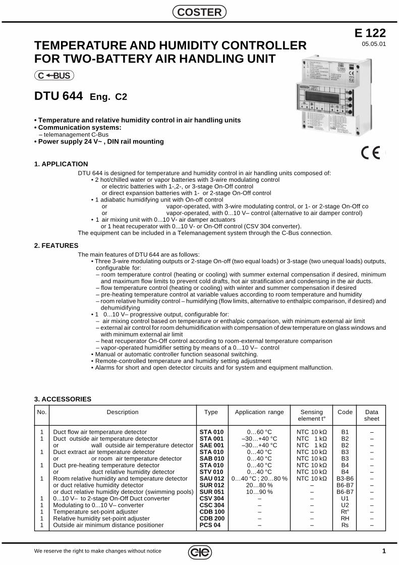
1. APPLICATIONDTU 644 is designed for temperature and humidity control in air handling units composed of:
• 2 hot/chilled water or vapor batteries with 3-wire modulating controlor electric batteries with 1-,2-, or 3-stage On-Off controlor direct expansion batteries with 1- or 2-stage On-Off control
• 1 adiabatic humidifying unit with On-off controlor vapor-operated, with 3-wire modulating control, or 1- or 2-stage On-Off coor vapor-operated, with 0...10 V– control (alternative to air damper control)
• 1 air mixing unit with 0...10 V- air damper actuatorsor 1 heat recuperator with 0...10 V- or On-Off control (CSV 304 converter).
The equipment can be included in a Telemanagement system through the C-Bus connection.
2. FEATURESThe main features of DTU 644 are as follows:
• Three 3-wire modulating outputs or 2-stage On-off (two equal loads) or 3-stage (two unequal loads) outputs,configurable for:– room temperature control (heating or cooling) with summer external compensation if desired, minimum
and maximum flow limits to prevent cold drafts, hot air stratification and condensing in the air ducts.– flow temperature control (heating or cooling) with winter and summer compensation if desired– pre-heating temperature control at variable values according to room temperature and humidity– room relative humidity control – humidifying (flow limits, alternative to enthalpic comparison, if desired) and
dehumidifying• 1 0...10 V– progressive output, configurable for:
– air mixing control based on temperature or enthalpic comparison, with minimum external air limit– external air control for room dehumidification with compensation of dew temperature on glass windows and
with minimum external air limit– heat recuperator On-Off control according to room-external temperature comparison– vapor-operated humidifier setting by means of a 0...10 V– control
• Manual or automatic controller function seasonal switching.• Remote-controlled temperature and humidity setting adjustment• Alarms for short and open detector circuits and for system and equipment malfunction.
C BUS
3. ACCESSORIES
No. Description Type Application range Sensing Code Dataelement t° sheet
1 Duct flow air temperature detector STA 010 0…60 °C NTC 10 kΩ B1 –1 Duct outside air temperature detector STA 001 –30…+40 °C NTC 1 kΩ B2 –
or wall outside air temperature detector SAE 001 –30…+40 °C NTC 1 kΩ B2 –1 Duct extract air temperature detector STA 010 0…40 °C NTC 10 kΩ B3 –
or or room air temperature detector SAB 010 0…40 °C NTC 10 kΩ B3 –1 Duct pre-heating temperature detector STA 010 0…40 °C NTC 10 kΩ B4 –
or duct relative humidity detector STV 010 0…40 °C NTC 10 kΩ B4 –1 Room relative humidity and temperature detector SAU 012 0…40 °C ; 20…80 % NTC 10 kΩ B3-B6 –
or duct relative humidity detector SUR 012 20…80 % – B6-B7 –or duct relative humidity detector (swimming pools) SUR 051 10…90 % – B6-B7 –
1 0...10 V– to 2-stage On-Off Duct converter CSV 304 – – U1 –1 Modulating to 0...10 V– converter CSC 304 – – U2 –1 Temperature set-point adjuster CDB 100 – – Rt° –1 Relative humidity set-point adjuster CDB 200 – – RH –1 Outside air minimum distance positioner PCS 04 – – Rs –
E 12205.05.01
2
E 122 - DTU 644 C2 Eng. 05.05.01
We reserve the right to make changes without notice
COSTER
AIR TREATMENTCONTROLLER
DTU 644COSTER
OUTPUT Y1
+
–
OUTPUT Ys
ESC
1 2
OUTPUT Y2
1 2
OUTPUT Y3
1 2
ALARM
!°c
105
115
35
50.5 21
45
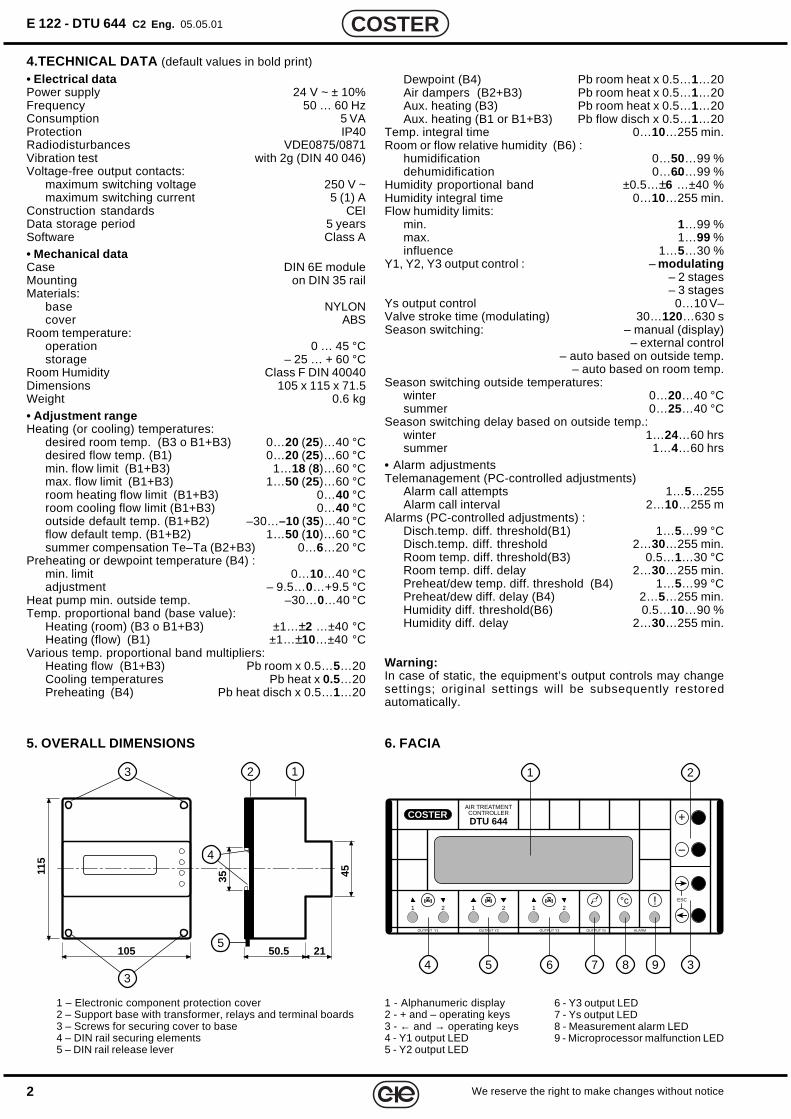
4.TECHNICAL DATA (default values in bold print)
• Electrical dataPower supply 24 V ~ ± 10%Frequency 50 … 60 HzConsumption 5 VAProtection IP40Radiodisturbances VDE0875/0871Vibration test with 2g (DIN 40 046)Voltage-free output contacts:
maximum switching voltage 250 V ~maximum switching current 5 (1) A
Construction standards CEIData storage period 5 yearsSoftware Class A• Mechanical dataCase DIN 6E moduleMounting on DIN 35 railMaterials:
base NYLONcover ABS
Room temperature:operation 0 … 45 °Cstorage – 25 … + 60 °C
Room Humidity Class F DIN 40040Dimensions 105 x 115 x 71.5Weight 0.6 kg• Adjustment rangeHeating (or cooling) temperatures:
desired room temp. (B3 o B1+B3) 0…20 (25)…40 °Cdesired flow temp. (B1) 0…20 (25)…60 °Cmin. flow limit (B1+B3) 1…18 (8)…60 °Cmax. flow limit (B1+B3) 1…50 (25)…60 °Croom heating flow limit (B1+B3) 0…40 °Croom cooling flow limit (B1+B3) 0…40 °Coutside default temp. (B1+B2) –30…–10 (35)…40 °Cflow default temp. (B1+B2) 1…50 (10)…60 °Csummer compensation Te–Ta (B2+B3) 0…6…20 °C
Preheating or dewpoint temperature (B4) :min. limit 0…10…40 °Cadjustment – 9.5…0…+9.5 °C
Heat pump min. outside temp. –30…0…40 °CTemp. proportional band (base value):
Heating (room) (B3 o B1+B3) ±1…±2 …±40 °CHeating (flow) (B1) ±1…±10…±40 °C
Various temp. proportional band multipliers:Heating flow (B1+B3) Pb room x 0.5…5…20Cooling temperatures Pb heat x 0.5…20Preheating (B4) Pb heat disch x 0.5…1…20
5. OVERALL DIMENSIONS 6. FACIA
1 - Alphanumeric display2 - + and – operating keys3 - ← and → operating keys4 - Y1 output LED5 - Y2 output LED
123
3
4
5
1 – Electronic component protection cover2 – Support base with transformer, relays and terminal boards3 – Screws for securing cover to base4 – DIN rail securing elements5 – DIN rail release lever
Dewpoint (B4) Pb room heat x 0.5…1…20Air dampers (B2+B3) Pb room heat x 0.5…1…20Aux. heating (B3) Pb room heat x 0.5…1…20Aux. heating (B1 or B1+B3) Pb flow disch x 0.5…1…20
Temp. integral time 0…10…255 min.Room or flow relative humidity (B6) :
humidification 0…50…99 %dehumidification 0…60…99 %
Humidity proportional band ±0.5…±6 …±40 %Humidity integral time 0…10…255 min.Flow humidity limits:
min. 1…99 %max. 1…99 %influence 1…5…30 %
Y1, Y2, Y3 output control : – modulating– 2 stages– 3 stages
Ys output control 0…10 V–Valve stroke time (modulating) 30…120…630 sSeason switching: – manual (display)
– external control– auto based on outside temp.
– auto based on room temp.Season switching outside temperatures:
winter 0…20…40 °Csummer 0…25…40 °C
Season switching delay based on outside temp.:winter 1…24…60 hrssummer 1…4…60 hrs
• Alarm adjustmentsTelemanagement (PC-controlled adjustments)
Alarm call attempts 1…5…255Alarm call interval 2…10…255 m
Alarms (PC-controlled adjustments) :Disch.temp. diff. threshold(B1) 1…5…99 °CDisch.temp. diff. threshold 2…30…255 min.Room temp. diff. threshold(B3) 0.5…1…30 °CRoom temp. diff. delay 2…30…255 min.Preheat/dew temp. diff. threshold (B4) 1…5…99 °CPreheat/dew diff. delay (B4) 2…5…255 min.Humidity diff. threshold(B6) 0.5…10…90 %Humidity diff. delay 2…30…255 min.
Warning:In case of static, the equipment’s output controls may changesettings; original settings will be subsequently restoredautomatically.
1 2
4 5 6 37 8 9
6 - Y3 output LED7 - Ys output LED8 - Measurement alarm LED9 - Microprocessor malfunction LED
3We reserve the right to make changes without notice
COSTER
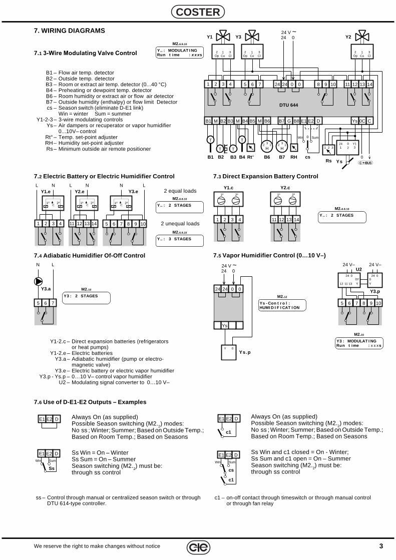
Always On (as supplied)Possible Season switching (M2.2) modes:No ss ; Winter; Summer; Based on Outside Temp.;Based on Room Temp.; Based on Seasons
Ss Win = On – WinterSs Sum = On – SummerSeason switching (M2.2) must be:through ss control
7. WIRING DIAGRAMS
B1 – Flow air temp. detectorB2 – Outside temp. detectorB3 – Room or extract air temp. detector (0...40 °C)B4 – Preheating or dewpoint temp. detectorB6 – Room humidity or extract air or flow air detectorB7 – Outside humidity (enthalpy) or flow limit Detectorcs – Season switch (eliminate D-E1 link)
Win = winter Sum = summerY1-2-3 – 3-wire modulating controls
Ys – Air dampers or recuperator or vapor humidifier0...10V– control
Rt° – Temp. set-point adjusterRH – Humidity set-point adjusterRs – Minimum outside air remote positioner
7.6 Use of D-E1-E2 Outputs – Examples
ss – Control through manual or centralized season switch or throughDTU 614-type controller.
c1 – on-off contact through timeswitch or through manual controlor through fan relay
DE1 E2
1 2 3 4
LY1.e
N
1º 2º
LY2.e
N
1º 2º
11 12 13 141 2 3 4
1º 2º
Y1.c
11 12 13 14
1º 2º
Y2.c
5 6 7
Y3.a
N L
Y.. : MODULAT I NGRun t ime : x x x s
M2.6.8.10
7.1 3-Wire Modulating Valve Control
5 6 7 8 9 10
1º 2º
N LY3.e
7.2 Electric Battery or Electric Humidifier Control
Y.. : 2 STAGES
M2.6.8.10
7.4 Adiabatic Humidifier Of-Off Control
2 equal loads
Y.. : 3 STAGES
M2.6.8.10
Y.. : 2 STAGES
M2.6.8.10
7.3 Direct Expansion Battery Control
Y3 : MODULAT I NGRun t ime : x x x s
M2.10
Y3 : 2 STAGES
M2.10
2 unequal loads
Y1-2.c – Direct expansion batteries (refrigeratorsor heat pumps)
Y1-2.e – Electric batteriesY3.a – Adiabatic humidifier (pump or electro-
magnetic valve)Y3.e – Electric battery or electric vapor humidifier
Y3.p - Ys.p – 0…10 V– control vapor humidifierU2 – Modulating signal converter to 0…10 V–
5 6 7 8 9 10
24 V–
Y3.p
24 V–
0240Y
U2
1112 13
0240YY
7.5 Vapor Humidifier Control (0…10 V–)
024 V ~24
24 0 024
Ys
Ys.pY 0
Ys - Con t r o l :HUMI D I F I CAT I ON
M2.12
Always On (as supplied)Possible Season switching (M2.2) modes:No ss ; Winter; Summer; Based on Outside Temp.;Based on Room Temp.; Based on Seasons
Ss Win and c1 closed = On - Winter;Ss Sum and c1 open = On – SummerSeason switching (M2.2) must be:through ss control
Rs
1 32
Y1
1Co
3Cl
2Op
B2B1
024 V ~24
MB5B4MB3B2MB1
11 12 13 14
DTU 644
B6
5 6 7 24 0 0 8 9 10
Rt°B3
Y2
B7 G
RH
241 2 3 4
0
DE2
C BUS
B8 E1 CYs 0C
B6
H3 12
1Co
3Cl
2Op
Y3
1Co
3Cl
2Op
Ys
T
T T241
Y13
02
B4
T
B7
H3 12
cs
0Win Sum
DE1 E2
Ss
Win Sum Win
DE1 E2
cs
Sum
c1
c1
DE1 E2
4
E 122 - DTU 644 C2 Eng. 05.05.01
We reserve the right to make changes without notice
COSTER
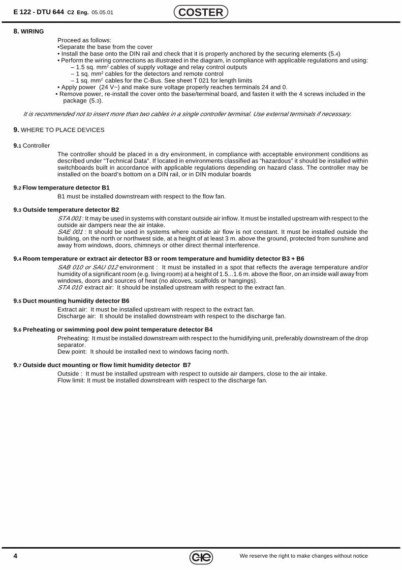
9. WHERE TO PLACE DEVICES
9.1 ControllerThe controller should be placed in a dry environment, in compliance with acceptable environment conditions asdescribed under “Technical Data”. If located in environments classified as “hazardous” it should be installed withinswitchboards built in accordance with applicable regulations depending on hazard class. The controller may beinstalled on the board’s bottom on a DIN rail, or in DIN modular boards
9.2 Flow temperature detector B1B1 must be installed downstream with respect to the flow fan.
9.3 Outside temperature detector B2STA 001 : It may be used in systems with constant outside air inflow. It must be installed upstream with respect to theoutside air dampers near the air intake.SAE 001 : It should be used in systems where outside air flow is not constant. It must be installed outside thebuilding, on the north or northwest side, at a height of at least 3 m. above the ground, protected from sunshine andaway from windows, doors, chimneys or other direct thermal interference.
9.4 Room temperature or extract air detector B3 or room temperature and humidity detector B3 + B6SAB 010 or SAU 012 environment : It must be installed in a spot that reflects the average temperature and/orhumidity of a significant room (e.g. living room) at a height of 1.5...1.6 m. above the floor, on an inside wall away fromwindows, doors and sources of heat (no alcoves, scaffolds or hangings).STA 010 extract air: It should be installed upstream with respect to the extract fan.
9.5 Duct mounting humidity detector B6Extract air: It must be installed upstream with respect to the extract fan.Discharge air: It should be installed downstream with respect to the discharge fan.
9.6 Preheating or swimming pool dew point temperature detector B4Preheating: It must be installed downstream with respect to the humidifying unit, preferably downstream of the dropseparator.Dew point: It should be installed next to windows facing north.
9.7 Outside duct mounting or flow limit humidity detector B7Outside : It must be installed upstream with respect to outside air dampers, close to the air intake.Flow limit: It must be installed downstream with respect to the discharge fan.
8. WIRINGProceed as follows:•Separate the base from the cover• Install the base onto the DIN rail and check that it is properly anchored by the securing elements (5.4)• Perform the wiring connections as illustrated in the diagram, in compliance with applicable regulations and using:
– 1.5 sq. mm2 cables of supply voltage and relay control outputs– 1 sq. mm2 cables for the detectors and remote control– 1 sq. mm2 cables for the C-Bus. See sheet T 021 for length limits
• Apply power (24 V~) and make sure voltage properly reaches terminals 24 and 0.• Remove power, re-install the cover onto the base/terminal board, and fasten it with the 4 screws included in the
package (5.3).
It is recommended not to insert more than two cables in a single controller terminal. Use external terminals if necessary.
5We reserve the right to make changes without notice
COSTER
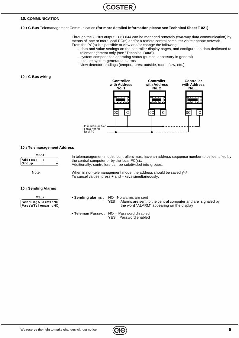
10.3 Telemanagement Address
In telemanagement mode, controllers must have an address sequence number to be identified bythe central computer or by the local PC(s),.Additionally, controllers can be subdivided into groups.
Note When in non-telemanagement mode, the address should be saved (–).To cancel values, press + and – keys simultaneously.
10.4 Sending Alarms
• Sending alarms : NO= No alarms are sentYES = Alarms are sent to the central computer and are signaled by
the word “ALARM” appearing on the display
• Teleman Passw: : NO = Password disabledYES = Password enabled
M2.14
Add r e s s : –Gr oup : –
M2.13
Send i ngA l a rms : NOPa s sWTe l eman : NO
10. COMMUNICATION
10.1 C-Bus Telemanagement Communication (for more detailed information please see Technical Sheet T 021)
Through the C-Bus output, DTU 644 can be managed remotely (two-way data communication) bymeans of one or more local PC(s) and/or a remote central computer via telephone network.From the PC(s) it is possible to view and/or change the following:
– data and value settings on the controller display pages, and configuration data dedicated totelemanagement only (see “Technical Data”)
– system component’s operating status (pumps, accessory in general)– acquire system-generated alarms– view detector readings (temperatures: outside, room, flow, etc.)
10.2 C-Bus wiring
C0C C0C C0C
Controllerwith Address
No. 1
Controllerwith Address
No. 2
Controllerwith Address
No. ...
to modem and/orconvertor forlocal PC
6
E 122 - DTU 644 C2 Eng. 05.05.01
We reserve the right to make changes without notice
COSTER
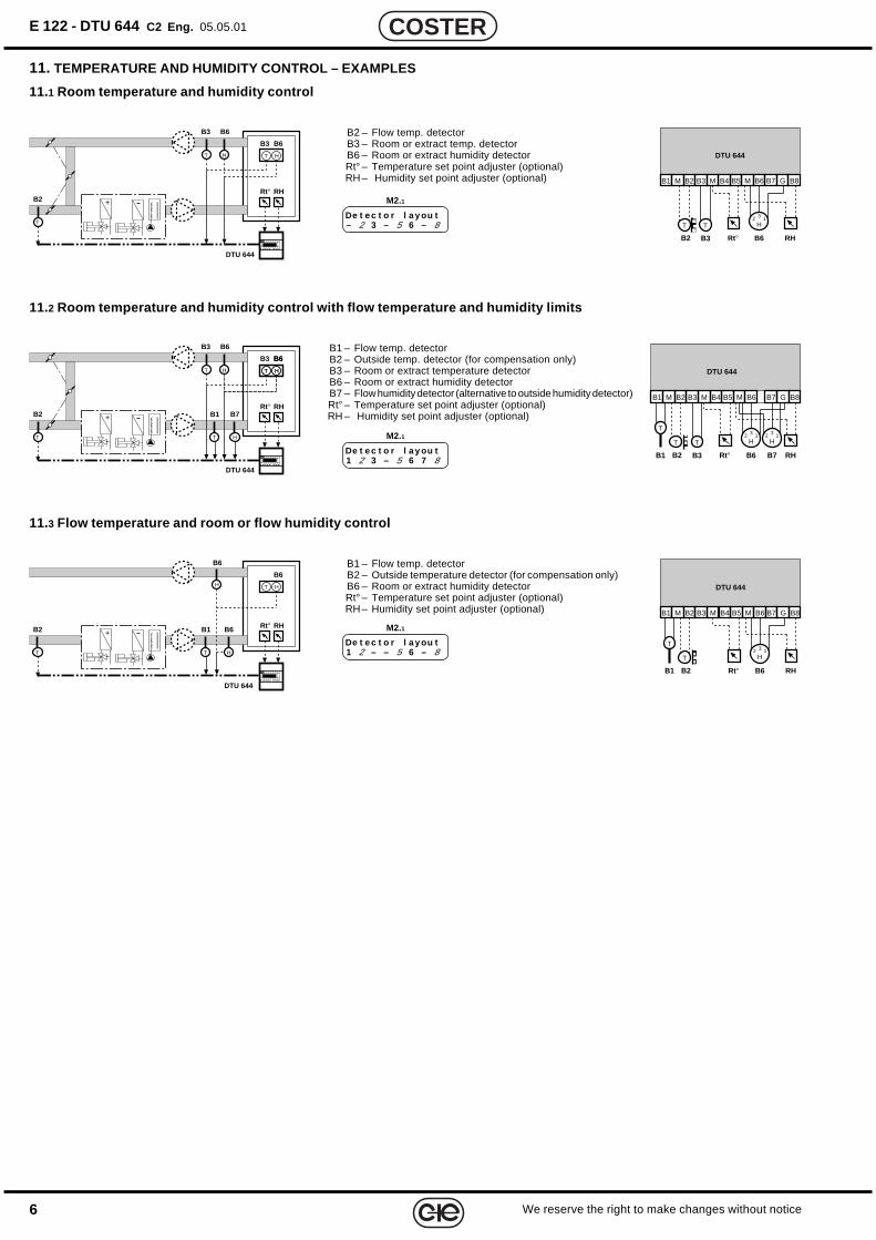
11. TEMPERATURE AND HUMIDITY CONTROL – EXAMPLES
11.1 Room temperature and humidity control
B2 – Flow temp. detectorB3 – Room or extract temp. detectorB6 – Room or extract humidity detectorRt° – Temperature set point adjuster (optional)RH – Humidity set point adjuster (optional)
B1 – Flow temp. detectorB2 – Outside temp. detector (for compensation only)B3 – Room or extract temperature detectorB6 – Room or extract humidity detectorB7 – Flow humidity detector (alternative to outside humidity detector)Rt° – Temperature set point adjuster (optional)RH – Humidity set point adjuster (optional)
B1 – Flow temp. detectorB2 – Outside temperature detector (for compensation only)B6 – Room or extract humidity detectorRt° – Temperature set point adjuster (optional)RH – Humidity set point adjuster (optional)
11.2 Room temperature and humidity control with flow temperature and humidity limits
11.3 Flow temperature and room or flow humidity control
De t e c t o r l a y ou t– 2 3 – 5 6 – 8
M2.1
De t e c t o r l a y ou t1 2 3 – 5 6 7 8
M2.1
De t e c t o r l a y ou t1 2 – – 5 6 – 8
M2.1
B6B3
B2
DTU 644
T
HT
RHRt°
+++
T H
B6B3
B2
MB5B4MB3B2MB1
DTU 644
B6
Rt°B3
B7 G
RH
B8
B6
H3 12
T T
B2
DTU 644
T
B1
T H
B6+++
RHRt°
B6
H T H
B6
B2B1
MB5B4MB3B2MB1
DTU 644
B6
Rt°
B7 G
RH
B8
B6
H3 12
T
T
B6B3
B2
DTU 644
T
B1
T
HT
+++RHRt°
T H
B6B3
T H
B6
B7
H
B2B1
MB5B4MB3B2MB1
DTU 644
B6
Rt°B3
B7 G
RH
B8
T
T T
B6
H3 12
B7
H3 12
7We reserve the right to make changes without notice
COSTER
B3
B2
DTU 644
T
T
MYs
U1
+++
B2
024 V ~24
MB5B4MB3B2MB1
DTU 644
B6
24 0 0
B3
B7 G
24
DE2B8 E1 CYs 0C
U1T T241
Y13
02
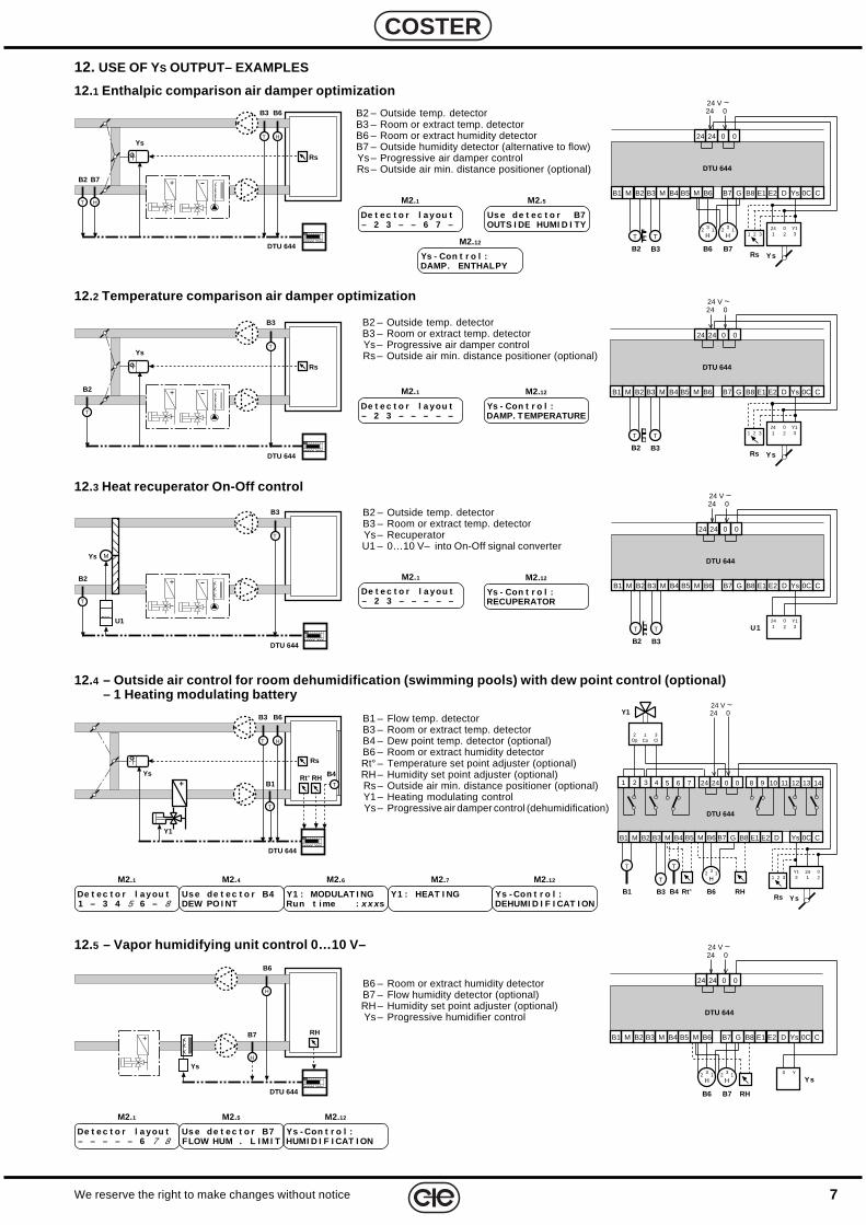
12. USE OF YS OUTPUT– EXAMPLES
12.1 Enthalpic comparison air damper optimization
12.2 Temperature comparison air damper optimization
12.3 Heat recuperator On-Off control
B2 – Outside temp. detectorB3 – Room or extract temp. detectorB6 – Room or extract humidity detectorB7 – Outside humidity detector (alternative to flow)Ys – Progressive air damper controlRs – Outside air min. distance positioner (optional)
B2 – Outside temp. detectorB3 – Room or extract temp. detectorYs – Progressive air damper controlRs – Outside air min. distance positioner (optional)
B2 – Outside temp. detectorB3 – Room or extract temp. detectorYs – RecuperatorU1 – 0…10 V– into On-Off signal converter
De t e c t o r l a y ou t– 2 3 – – 6 7 –
M2.1
De t e c t o r l a you t– 2 3 – – – – –
M2.1
De t e c t o r l a you t– 2 3 – – – – –
M2.1
Ys - Con t r o l :DAMP. T EMPERATURE
M2.12
Ys - Con t r o l :RECUPERATOR
M2.12
12.4 – Outside air control for room dehumidification (swimming pools) with dew point control (optional)– 1 Heating modulating battery
De t e c t o r l a y ou t1 – 3 4 5 6 – 8
M2.1
Y1 : MODULAT I NGRun t ime : x x x s
M2.6
Y1 : HEAT I NG
M2.7
Ys - Con t r o l :DEHUMI D I F I CAT I ON
M2.12
B1 – Flow temp. detectorB3 – Room or extract temp. detectorB4 – Dew point temp. detector (optional)B6 – Room or extract humidity detectorRt° – Temperature set point adjuster (optional)RH – Humidity set point adjuster (optional)Rs – Outside air min. distance positioner (optional)Y1 – Heating modulating controlYs – Progressive air damper control (dehumidification)
Us e de t e c t o r B4DEW PO I NT
M2.4
B3
B2
Ys
DTU 644
T
T
Rs
+++B7
H
B6
H
Rs
1 32
B2
024 V ~24
MB5B4MB3B2MB1
DTU 644
B6
24 0 0
B3
B7 G
24
DE2B8 E1 CYs 0C
B6
H3 12
Ys
T T241
Y13
02
B7
H3 12
B3
B2
Ys
DTU 644
T
T
Rs
+++
Rs
1 32
B2
024 V ~24
MB5B4MB3B2MB1
DTU 644
B6
24 0 0
B3
B7 G
24
DE2B8 E1 CYs 0C
Ys
T T241
Y13
02
Ys - Con t r o l :DAMP. ENTHALPY
M2.12
DTU 644
Ys
+++
B6
H
B7
H
RH
12.5 – Vapor humidifying unit control 0…10 V–0
24 V ~24
MB5B4MB3B2MB1
DTU 644
B6
24 0 0
B7 G
24
DE2B8 E1 CYs 0C
YsY0
RHB6
H3 12
B7
H3 12
B6 – Room or extract humidity detectorB7 – Flow humidity detector (optional)RH – Humidity set point adjuster (optional)Ys – Progressive humidifier control
De t e c t o r l a you t– – – – – 6 7 8
M2.1
Ys - Con t r o l :HUMI D I F I CAT I ON
M2.12
Us e de t e c t o r B7FLOW HUM . L I M I T
M2.5
Us e de t e c t o r B7OUTS I DE HUMI D I TY
M2.5
Y1
YsRH B4
Rs
Rt°T
B6B3
DTU 644
B1
T
HT
+
Rs
1 32
Y1
1Co
3Cl
2Op
B1
024 V ~24
MB5B4MB3B2MB1
11 12 13 14
DTU 644
B6
5 6 7 24 0 0 8 9 10
Rt°B3
B7 G
RH
241 2 3 4
DE2B8 E1 CYs 0C
B6
H3 12
Ys
T
T241
Y13
02
B4
T
8
E 122 - DTU 644 C2 Eng. 05.05.01
We reserve the right to make changes without notice
COSTER
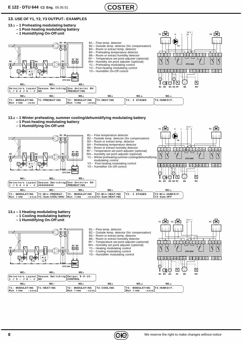
13. USE OF Y1, Y2, Y3 OUTPUT– EXAMPLES
13.2 – 1 Winter preheating, summer cooling/dehumidifying modulating battery– 1 Post-heating modulating battery– 1 Humidifying On-Off unit
B1 – Flow temp. detectorB2 – Outside temp. detector (for compensation)B3 – Room or extract temp. detectorB4 – Preheating temperature detectorB6 – Room or extract humidity detectorRt° – Temperature set point adjuster (optional)RH – Humidity set point adjuster (optional)Y1 – Preheating modulating controlY2 – Post-heating modulating controlY3 – Humidifier On-Off control
De t e c t o r s La y ou t1 2 3 4 5 6 – 8
M2.1
Y1 : MODULAT I NGRun t ime : x x x s
M2.6
Y1 : PREHEAT I NG
M2.7
Y2 : MODULAT I NGRun t ime : x x x s
M2.8
Y2 : HEAT I NG
M2.9
Y3 : 2 STAGES
M2.10
Y3 : HUMI D I F .
M2.11
De t e c t o r s La y ou t1 2 3 4 5 6 – 8
M2.1
Y1 : MODULAT I NGRun t ime : x x xs
M2.6
Y1 -Wi n : PREHEAT .Y1 - Sum: COOL+DHU
M2.7
Y2 : MODULAT I NGRun t ime : x x xs
M2.8
Y2 -Wi n : HEAT I NGY2 - Sum: HEAT I NG
M2.9
Y3 : 2 STAGES
M2.10
Y3 -Wi n : HUMI D I F .Y3 - Sum: OFF
M2.11
B1 – Flow temperature detectorB2 – Outside temp. detector (for compensation)B3 – Room or extract temp. detectorB4 – Preheating temperature detectorB6 – Room or extract humidity detectorRt° – Temperature set point adjuster (optional)RH – Humidity set point adjuster (optional)Y1 – Winter preheating summer cooling/dehumidifying
modulating controlY2 – Post-heating modulating controlY3 – Humidifier On-Off control
13.1 – 1 Preheating modulating battery– 1 Post-heating modulating battery– 1 Humidifying On-Off unit
13.3 – 1 Heating modulating battery– 1 Cooling modulating battery– 1 Humidifying On-Off unit
B1 – Flow temp. detectorB2 – Outside temp. detector (for compensation)B3 – Room or extract temp. detectorB6 – Room or extract humidity detectorRt° – Temperature set point adjuster (optional)RH – Humidity set point adjuster (optional)Y1 – Heating modulating controlY2 – Cooling modulating controlY3 – Humidifier modulating control
De t e c t o r s La y ou t1 2 3 – 5 6 – 8
M2.1
Y1 : MODULAT I NGRun t ime : x x xs
M2.6
Y1 : HEAT I NG
M2.7
Y2 : MODULAT I NGRun t ime : x x xs
M2.8
Y2 : COOL I NG
M2.9
Y3 : MODULAT I NGRun t ime : x x xs
M2.10
Y3 : HUMI D I F .
M2.11
Us e de t e c t o r B4PREHEAT I NG
M2.4
Us e de t e c t o r B4PREHEAT I NG
M2.4
Ou t pu t 8 - 9 - 1 0 :CONTROL
M2.3
Se a son Sw i t c h i ngNO
M2.2
Se a son Sw i t c h i ngXXXXXXXXX
M2.2
Se a son Sw i t c h i ngNO
M2.2
Y3Y1 Y2
+B4
T
+
B6B3
B2
DTU 644
T
B1
T
HT
RHRt°
Y3Y1 Y2
+B4
T
+–
B6B3
B2
DTU 644
T
B1
T
HT
RHRt°
Y3Y2Y1
–+
B6B3
B2
DTU 644
T
B1
T
HT
RHRt°
Y1
1Co
3Cl
2Op
B2B1
024 V ~24
MB5B4MB3B2MB1
11 12 13 14
DTU 644
B6
5 6 7 24 0 0 8 9 10
Rt°B3
Y2
B7 G
RH
241 2 3 4
DE2B8 E1 CYs 0C
B6
H3 12
1Co
3Cl
2Op
T
T T
B4
T
Y3
N L
Y1
1Co
3Cl
2Op
B2B1
024 V ~24
MB5B4MB3B2MB1
11 12 13 14
DTU 644
B6
5 6 7 24 0 0 8 9 10
Rt°B3
Y2
B7 G
RH
241 2 3 4
DE2B8 E1 CYs 0C
B6
H3 12
1Co
3Cl
2Op
T
T T
B4
T
Y3
N L
Y1
1Co
3Cl
2Op
B2B1
024 V ~24
MB5B4MB3B2MB1
11 12 13 14
DTU 644
B6
5 6 7 24 0 0 8 9 10
Rt°B3
Y2
B7 G
RH
241 2 3 4
DE2B8 E1 CYs 0C
B6
H3 12
1Co
3Cl
2Op
Y3
1Co
3Cl
2Op
T
T T
9We reserve the right to make changes without notice
COSTER
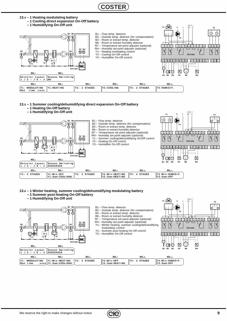
13.4 – 1 Heating modulating battery– 1 Cooling direct expansion On-Off battery– 1 Humidifying On-Off unit
B1 – Flow temp. detectorB2 – Outside temp. detector (for compensation)B3 – Room or extract temp. detectorB6 – Room or extract humidity detectorRt° – Temperature set point adjuster (optional)RH – Humidity set point adjuster (optional)Y1 – Heating modulating controlY2 – Cooling On-Off controlY3 – Humidifier On-Off control
De t e c t o r La you t1 2 3 – 5 6 – 8
M2.1
Y1 : MODULAT I NGRun t ime : x x x s
M2.6
Y1 : HEAT I NG
M2.7
Y2 : 2 STAGES
M2.8
Y2 : COOL I NG
M2.9
Y3 : 2 STAGES
M2.10
Y3 : HUMI D I F .
M2.11
Se a son Sw i t c h i ngNO
M2.2
13.5 – 1 Summer cooling/dehumidifying direct expansion On-Off battery– 1 Heating On-Off battery– 1 Humidifying On-Off unit
B1 – Flow temp. detectorB2 – Outside temp. detector (for compensation)B3 – Room or extract temp. detectorB6 – Room or extract humidity detectorRt° – Temperature set point adjuster (optional)RH – Humidity set point adjuster (optional)Y1 – Summer cooling/dehumidifying On/Off controlY2 – Heating On-Off controlY3 – Humidifier On-Off control
De t e c t o r La you t1 2 3 – 5 6 – 8
M2.1
Y1 : 2 STAGES
M2.6
Y1 -Wi n : OFFY1 - Sum: COOL+DHU
M2.7
Y2 : 2 STAGES
M2.8
Y2 -Wi n : HEAT I NGY2 - Sum: HEAT I NG
M2.9
Y3 : 2 STAGES
M2.10
Y3 -Wi n : HUMI D I F .Y3 - Sum: OFF
M2.11
Se a son Sw i t c h i ngXXXXXXXXX
M2.2
13.6 – 1 Winter heating, summer cooling/dehumidifying modulating battery– 1 Summer post-heating On-Off battery– 1 Humidifying On-Off unit
B1 – Flow temp. detectorB2 – Outside temp. detector (for compensation)B3 – Room or extract temp. detectorB6 – Room or extract humidity detectorRt° – Temperature set point adjuster (optional)RH – Humidity set point adjuster (optional)Y1 – Winter heating, summer cooling/dehumidifying
modulating controlY2 – Summer post-heating On-Off controlY3 – Humidifier On-Off control
De t e c t o r La you t1 2 3 – 5 6 – 8
M2.1
Y1 : MODULAT I NGRun t ime : x x x s
M2.6
Y1 -Wi n : HEAT I NGY1 - Sum: COOL+DHU
M2.7
Y2 : 2 STAGES
M2.8
Y2 -Wi n : OFFY2 - Sum: HEAT I NG
M2.9
Y3 : 2 STAGES
M2.10
Y3 -Wi n : HUMI D I F .Y3 - Sum: OFF
M2.11
Se a son Sw i t c h i ngXXXXXXXXX
M2.2
Y3Y2
–
Y1
+
B6B3
B2
DTU 644
T
B1
T
HT
RHRt°
Y3Y1
–
Y2
B6B3
B2
DTU 644
T
B1
T
HT
RHRt°
1º 2º
Y2
B2B1
024 V ~24
MB5B4MB3B2MB1
11 12 13 14
DTU 644
B6
5 6 7 24 0 0 8 9 10
Rt°B3
B7 G
RH
241 2 3 4
DE2B8 E1 CYs 0C
B6
H3 12
T
T T
Y3
N LY1
1º 2º
Y1 Y3 Y2
+–
B6B3
B2
DTU 644
T
B1
T
HT
RHRt°
1º 2º
Y1
1Co
3Cl
2Op
B2B1
024 V ~24
MB5B4MB3B2MB1
11 12 13 14
DTU 644
B6
5 6 7 24 0 0 8 9 10
Rt°B3
Y2
B7 G
RH
241 2 3 4
DE2B8 E1 CYs 0C
B6
H3 12
T
T T
Y3
N L
Y1
1Co
3Cl
2Op
B2B1
024 V ~24
MB5B4MB3B2MB1
11 12 13 14
DTU 644
B6
5 6 7 24 0 0 8 9 10
Rt°B3
Y2
B7 G
RH
241 2 3 4
DE2B8 E1 CYs 0C
B6
H3 12
T
T T
1º 2º
Y3
N L
10
E 122 - DTU 644 C2 Eng. 05.05.01
We reserve the right to make changes without notice
COSTER
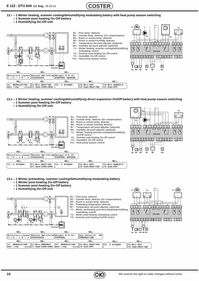
13.7 – 1 Winter heating, summer cooling/dehumidifying modulating battery with heat pump season switching– 1 Summer post-heating On-Off battery– 1 Humidifying On-Off unit
B1 – Flow temp. detectorB2 – Outside temp. detector (for compensation)B3 – Room or extract temp. detectorB6 – Room or extract humidity detectorRt° – Temperature set point adjuster (optional)RH – Humidity set point adjuster (optional)Y1 – Winter heating, summer cooling/dehumidifying
modulating controlY2 – Summer post-heating On-Off controlY3 – Humidifier On-Off control
Ycs – Heat pump season control
De t e c t o r s La y ou t1 2 3 – 5 6 – 8
M2.1
Y1 : MODULAT I NGRun t ime : x x xs
M2.6
Y1 -Wi n : HEAT I NGY1 - Sum: COOL+DHU
M2.7
Y2 : 2 STAGES
M2.8
Y2 -Wi n : OFFY2 - Sum: HEAT I NG
M2.9
Y3 -Wi n : HUMI D I F .Y3 - Sum: OFF
M2.11
Se a son Sw i t c h i ngXXXXXXXXX
M2.2
Ou t pu t 8 - 9 - 1 0 :CONTROL SEASON
M2.3
13.8 – 1 Winter heating, summer cooling/dehumidifying direct expansion On/Off battery with heat pump season switching– 1 Summer post-heating On-Off battery– 1 Humidifying On-Off unit
B1 – Flow temp. detectorB2 – Outside temp. detector (for compensation)B3 – Room or extract temp. detectorB6 – Room or extract humidity detectorRt° – Temperature set point adjuster (optional)RH – Humidity set point adjuster (optional)Y1 – Winter heating,summercooling/dehumidifying
On/Off controlY2 – Summer post-heating On-Off controlY3 – Humidifier On-Off control
Ycs – Heat pump season control
De t e c t o r s La y ou t1 2 3 – 5 6 – 8
M2.1
Y1 : 2 STAGES
M2.6
Y1 -Wi n : HEAT I NGY1 - Sum: COOL+DHU
M2.7
Y2 : 2 STAGES
M2.8
Y2 -Wi n : OFFY2 - Sum: HEAT I NG
M2.9
Y3 -Wi n : HUMI D I F .Y3 - Sum: OFF
M2.11
Se a son Sw i t c h i ngXXXXXXXXX
M2.2
Ou t pu t 8 - 9 - 1 0 :CONTROL SEASON
M2.3
13.9 – 1 Winter preheating, summer cooling/dehumidifying modulating battery– 1 Winter post-heating On-Off battery– 1 Summer post-heating On-Off battery– 1 Humidifying On-Off unit
B1 – Flow temp. detectorB2 – Outside temp. detector (for compensation)B3 – Room or extract temp. detectorB4 – Preheating temperature detectorRt° – Temperature set point adjuster (optional)Y1 – Winter preheating,summercooling/dehumidifying
modulating controlY2 – Winter post-heating modulating controlY3 – Summer post-heating On/Off control
De t e c t o r s La y ou t1 2 3 – 5 6 – 8
M2.1
Y1 : MODULAT I NGRun t ime : x x xs
M2.6
Y1 -Wi n : PREHEAT .Y1 - Sum: COOL+DHU
M2.7
Y2 : MODULAT I NGRun t ime : x x xs
M2.8
Y2 -Wi n : HEAT I NGY2 - Sum: OFF
M2.9
Y3 -Wi n : OFFY3 - Sum: HEAT I NG
M2.11
Se a son Sw i t c h i ngXXXXXXXXX
M2.2
Ou t pu t 8 - 9 - 1 0 :CONTROL
M2.3
Y3 : 2 STAGES
M2.10
Us e de t e c t o r B4PREHEAT I NG
M2.4
Y1
Y3 Y2
Ycs
+–
B6B3
B2
DTU 644
T
B1
T
HT
RHRt°
Y1
+–
Y3 Y2Ycs
B6B3
B2
DTU 644
T
B1
T
HT
RHRt°
Y1 Y2
+B4+–
Y3
H
T
B3
B2
DTU 644
T
B1
T
T
Rt°
1º 2º
Y1
1Co
3Cl
2Op
B2B1
024 V ~24
MB5B4MB3B2MB1
11 12 13 14
DTU 644
B6
5 6 7 24 0 0 8 9 10
Rt°B3
Y2
B7 G
RH
241 2 3 4
DE2B8 E1 CYs 0C
B6
H3 12
T
T T
Y3
N L
Ycs
CoWinSum
Ycs
Y1
2ºSt
1º 2º
B2B1
024 V ~24
MB5B4MB3B2MB1
11 12 13 14
DTU 644
B6
5 6 7 24 0 0 8 9 10
Rt°B3
Y2
B7 G
RH
241 2 3 4
DE2B8 E1 CYs 0C
B6
H3 12
T
T T
Y3
N L
CoWin
Sum
1ºSt
Y1
1Co
3Cl
2Op
B2B1
024 V ~24
MB5B4MB3B2MB1
11 12 13 14
DTU 644
B6
5 6 7 24 0 0 8 9 10
Rt°B3
Y2
B7 G
241 2 3 4
DE2B8 E1 CYs 0C
1Co
3Cl
2Op
Y3
T
T T
B4
T
1º 2º
11We reserve the right to make changes without notice
COSTER
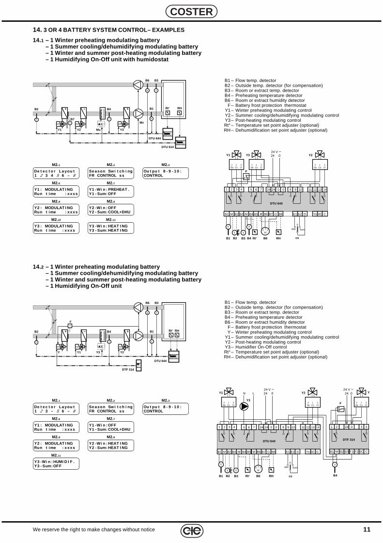
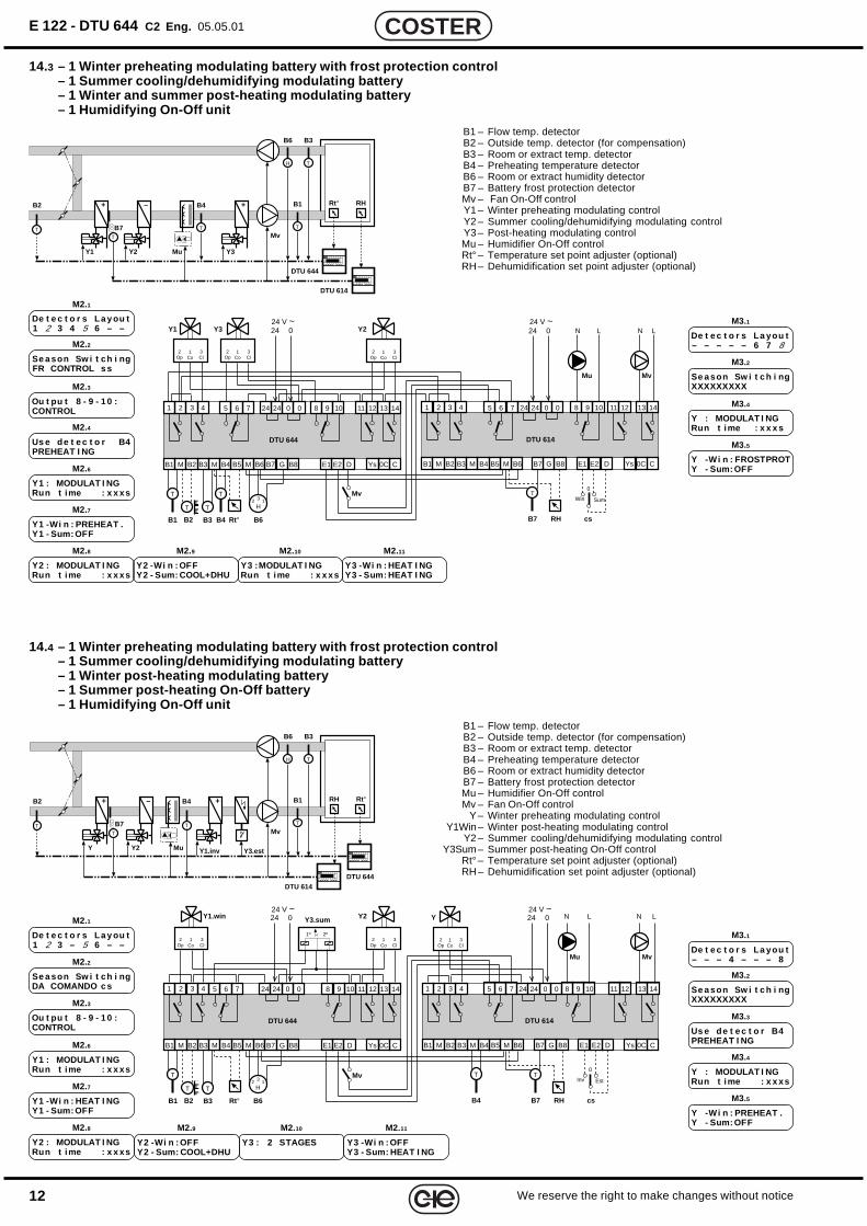
14. 3 OR 4 BATTERY SYSTEM CONTROL– EXAMPLES
14.1 – 1 Winter preheating modulating battery– 1 Summer cooling/dehumidifying modulating battery– 1 Winter and summer post-heating modulating battery– 1 Humidifying On-Off unit with humidostat
B1 – Flow temp. detectorB2 – Outside temp. detector (for compensation)B3 – Room or extract temp. detectorB4 – Preheating temperature detectorB6 – Room or extract humidity detector
F – Battery frost protection thermostatY – Winter preheating modulating control
Y1 – Summer cooling/dehumidifying modulating controlY2 – Post-heating modulating controlY3 – Humidifier On-Off controlRt° – Temperature set point adjuster (optional)RH – Dehumidification set point adjuster (optional)
De t e c t o r La you t1 2 3 – 5 6 – 8
M2.1
Y1 : MODULAT I NGRun t ime : x x x s
M2.6
Y1 -Wi n : OFFY1 - Sum: COOL+DHU
M2.7
Y2 : MODULAT I NGRun t ime : x x x s
M2.8
Y2 -Wi n : HEAT I NGY2 - Sum: HEAT I NG
M2.9
Y3 -Wi n : HUMI D I F .Y3 - Sum: OFF
M2.11
Se a son Sw i t ch i ngFR CONTROL s s
M2.2
Ou t pu t 8 - 9 - 1 0 :CONTROL
M2.3
14.2 – 1 Winter preheating modulating battery– 1 Summer cooling/dehumidifying modulating battery– 1 Winter and summer post-heating modulating battery– 1 Humidifying On-Off unit
B1 – Flow temp. detectorB2 – Outside temp. detector (for compensation)B3 – Room or extract temp. detectorB4 – Preheating temperature detectorB6 – Room or extract humidity detector
F – Battery frost protection thermostatY1 – Winter preheating modulating controlY2 – Summer cooling/dehumidifying modulating controlY3 – Post-heating modulating controlRt° – Temperature set point adjuster (optional)RH – Dehumidification set point adjuster (optional)
De t e c t o r La you t1 2 3 4 5 6 – 8
M2.1
Y1 : MODULAT I NGRun t ime : x x x s
M2.6
Y1 -Wi n : PREHEAT .Y1 - Sum: OFF
M2.7
Y2 : MODULAT I NGRun t ime : x x x s
M2.8
Y2 -Wi n : OFFY2 - Sum: COOL+DHU
M2.9
Y3 -Wi n : HEAT I NGY3 - Sum: HEAT I NG
M2.11
Se a son Sw i t ch i ngFR CONTROL s s
M2.2
Ou t pu t 8 - 9 - 1 0 :CONTROL
M2.3
Y3 : MODULAT I NGRun t ime : x x x s
M2.10
H T
T TT
B6
B1B2
Y Y1
B4
Y3
Rt° RH
F
B3
Y2
+ +–
DTU 644
DTF 314
T
H T
T TT
B6
B1B2
Y1 Y2
B4
Mu
Mv
Rt° RH
B7
B3
Y3
T
+ +–
DTU 644
DTU 614
Y1
1Co
3Cl
2Op
B2B1
MB5B4MB3B2MB1
11 12 13 14
DTU 644
B6
5 6 7 24 0 0 8 9 10
Rt°B3
Y2
B7 G
241 2 3 4
DE2B8 E1 CYs 0C
B6
H3 12
1Co
3Cl
2Op
T
T T
024 V ~24Y3
1Co
3Cl
2Op
cs
0
Win Sum
B4
T
RH
F
Y1
1Co
3Cl
2Op
B2B1
MB5B4MB3B2MB1
11 12 13 14
DTU 644
B6
5 6 7 24 0 0 8 9 10
Rt°B3
Y2
B7 G
241 2 3 4
DE2B8 E1 CYs 0C
B6
H3 12
1Co
3Cl
2Op
T
T T
024 V ~24
MB1
DTF 314
1 2 3 4
B4
F1B3 F2B2
024 V ~24 Y
1Co
3Cl
2Op
24 0
Y3
N L
T
cs
0
Win Sum
RH
0C C
F
12
E 122 - DTU 644 C2 Eng. 05.05.01
We reserve the right to make changes without notice
COSTER
14.4 – 1 Winter preheating modulating battery with frost protection control– 1 Summer cooling/dehumidifying modulating battery– 1 Winter post-heating modulating battery– 1 Summer post-heating On-Off battery– 1 Humidifying On-Off unit
B1 – Flow temp. detectorB2 – Outside temp. detector (for compensation)B3 – Room or extract temp. detectorB4 – Preheating temperature detectorB6 – Room or extract humidity detectorB7 – Battery frost protection detectorMu – Humidifier On-Off controlMv – Fan On-Off control
Y – Winter preheating modulating controlY1Win – Winter post-heating modulating control
Y2 – Summer cooling/dehumidifying modulating controlY3Sum – Summer post-heating On-Off control
Rt° – Temperature set point adjuster (optional)RH – Dehumidification set point adjuster (optional)
De t e c t o r s La you t– – – 4 – – – 8
M3.1De t e c t o r s La y ou t1 2 3 – 5 6 – –
M2.1
Y1 : MODULAT I NGRun t ime : x x xs
M2.6
Y1 -Wi n : HEAT I NGY1 - Sum: OFF
M2.7
Y2 : MODULAT I NGRun t ime : x x xs
M2.8
Y2 -Wi n : OFFY2 - Sum: COOL+DHU
M2.9
Y3 -Wi n : OFFY3 - Sum: HEAT I NG
M2.11
Se a son Sw i t ch i ngDA COMANDO c s
M2.2
Y3 : 2 STAGES
M2.10
Us e de t e c t o r B4PREHEAT I NG
M3.3
Y : MODULAT I NGRun t ime : x x xs
M3.4
Y -Wi n : PREHEAT .Y - Sum: OFF
M3.5
Ou t pu t 8 - 9 - 1 0 :CONTROL
M2.3
H T
T TT
B6
B1B2
Y Y2
B4
Mu
Mv
Rt°
B7
B3
Y1.inv
T
+ +–
DTU 644DTU 614
Y3.est
RH
Se a son Sw i t c h i ngXXXXXXXXX
M3.2
B1 – Flow temp. detectorB2 – Outside temp. detector (for compensation)B3 – Room or extract temp. detectorB4 – Preheating temperature detectorB6 – Room or extract humidity detectorB7 – Battery frost protection detectorMv – Fan On-Off controlY1 – Winter preheating modulating controlY2 – Summer cooling/dehumidifying modulating controlY3 – Post-heating modulating controlMu – Humidifier On-Off controlRt° – Temperature set point adjuster (optional)RH – Dehumidification set point adjuster (optional)
De t e c t o r s La you t– – – – – 6 7 8
M3.1De t e c t o r s La y ou t1 2 3 4 5 6 – –
M2.1
Y1 : MODULAT I NGRun t ime : x x xs
M2.6
Y1 -Wi n : PREHEAT .Y1 - Sum: OFF
M2.7
Y2 : MODULAT I NGRun t ime : x x xs
M2.8
Y2 -Wi n : OFFY2 - Sum: COOL+DHU
M2.9
Y3 -Wi n : HEAT I NGY3 - Sum: HEAT I NG
M2.11
Se a son Sw i t ch i ngFR CONTROL s s
M2.2
Y3 :MODULAT I NGRun t ime : x x xs
M2.10
Us e de t e c t o r B4PREHEAT I NG
M2.4Y : MODULAT I NGRun t ime : x x x s
M3.4
Se a son Sw i t c h i ngXXXXXXXXX
M3.2
H T
T TT
B6
B1B2
Y1 Y2
B4
Mu
Mv
Rt° RH
B7
B3
Y3
T
+ +–
DTU 644
DTU 614
Ou t pu t 8 - 9 - 1 0 :CONTROL
M2.3
14.3 – 1 Winter preheating modulating battery with frost protection control– 1 Summer cooling/dehumidifying modulating battery– 1 Winter and summer post-heating modulating battery– 1 Humidifying On-Off unit
Y -Wi n : FROSTPROTY - Sum: OFF
M3.5
Y1
1Co
3Cl
2Op
B2B1
MB5B4MB3B2MB1
11 12 13 14
DTU 644
B6
5 6 7 24 0 0 8 9 10
Rt°B3
Y2
B7 G
241 2 3 4
DE2B8 E1 CYs 0C
B6
H3 12
1Co
3Cl
2Op
T
T T
024 V ~24Y3
1Co
3Cl
2Op
MB1
11 12 13 14
DTU 614
5 6 7 24 0 0 8 9 10241 2 3 4
DE2E1 C0C
Mv
N L
B7
MB3 B4B2 MB5 B6 B7 G B8
T
024 V ~24
Ys
Mu
N L
Mv
cs
0
Win Sum
B4
T
RH
B2B1
MB5B4MB3B2MB1
11 12 13 14
DTU 644
B6
5 6 7 24 0 0 8 9 10
Rt°B3
Y2
B7 G
241 2 3 4
DE2B8 E1 CYs 0C
B6
H3 12
1Co
3Cl
2Op
Y3.sum
T
T T
Y
1Co
3Cl
2Op
B4
MB1
11 12 13 14
DTU 614
5 6 7 24 0 0 8 9 10241 2 3 4
DE2 C0C
T
Mv
N L
MB3 B4B2 MB5 B6 B7 E1G B8
Mu
N L
1Co
3Cl
2Op
Y1.win
1º 2º
024 V ~24 0
24 V ~24
Ys
Mv
cs
0
Inv Est
B7
T
RH
13We reserve the right to make changes without notice
COSTER
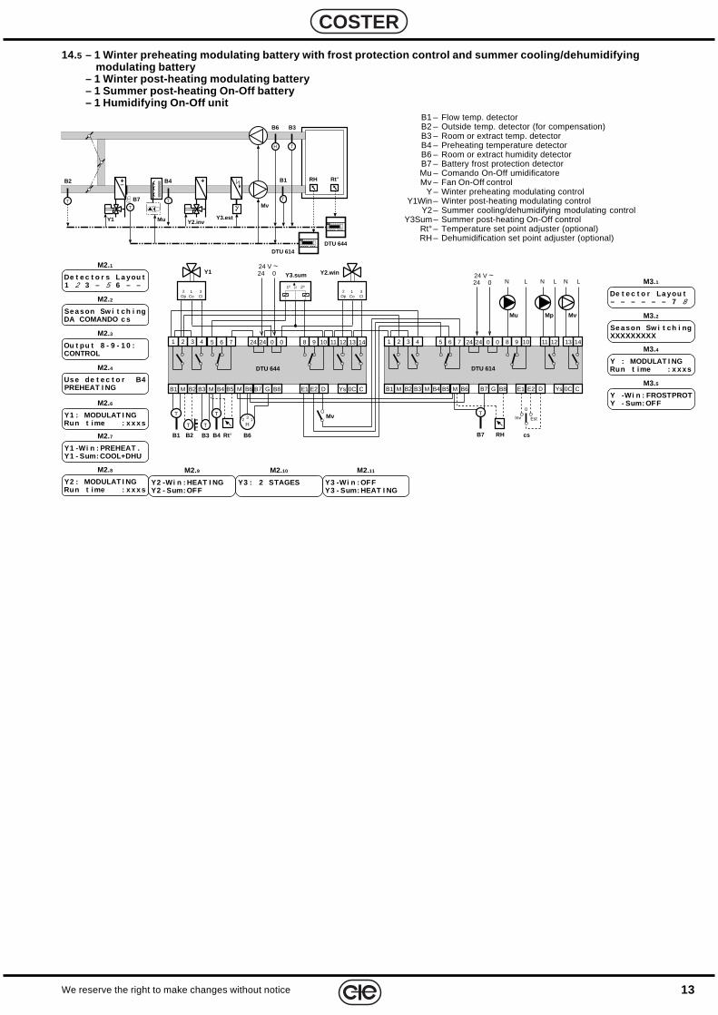
14.5 – 1 Winter preheating modulating battery with frost protection control and summer cooling/dehumidifyingmodulating battery
– 1 Winter post-heating modulating battery– 1 Summer post-heating On-Off battery– 1 Humidifying On-Off unit
B1 – Flow temp. detectorB2 – Outside temp. detector (for compensation)B3 – Room or extract temp. detectorB4 – Preheating temperature detectorB6 – Room or extract humidity detectorB7 – Battery frost protection detectorMu – Comando On-Off umidificatoreMv – Fan On-Off control
Y – Winter preheating modulating controlY1Win – Winter post-heating modulating control
Y2 – Summer cooling/dehumidifying modulating controlY3Sum – Summer post-heating On-Off control
Rt° – Temperature set point adjuster (optional)RH – Dehumidification set point adjuster (optional)
De t e c t o r La you t– – – – – – 7 8
M3.1De t e c t o r s La you t1 2 3 – 5 6 – –
M2.1
Y1 -Wi n : PREHEAT .Y1 - Sum: COOL+DHU
M2.7
Y2 -Wi n : HEAT I NGY2 - Sum: OFF
M2.9
Y3 -Wi n : OFFY3 - Sum: HEAT I NG
M2.11
Se a s on Sw i t ch i ngDA COMANDO c s
M2.2
Y : MODULAT I NGRun t ime : x x xs
M3.4
Y -Wi n : FROSTPROTY - Sum: OFF
M3.5Us e de t e c t o r B4PREHEAT I NG
M2.4
Ou t pu t 8 - 9 - 1 0 :CONTROL
M2.3Se a son Sw i t ch i ngXXXXXXXXX
M3.2
H T
T TT
B6
B1B2
Y1
B4
Mu
Mv
Rt°
B7
B3
Y2.inv
T
+–
+
DTU 644DTU 614
Y3.est
RH
Y3 : 2 STAGES
M2.10
Y1 : MODULAT I NGRun t ime : x x x s
M2.6
Y2 : MODULAT I NGRun t ime : x x x s
M2.8
B2B1
MB5B4MB3B2MB1
11 12 13 14
DTU 644
B6
5 6 7 24 0 0 8 9 10
Rt°B3
Y2.win
B7 G
241 2 3 4
DE2B8 E1 CYs 0C
B6
H3 12
1Co
3Cl
2Op
Y3.sum
T
T T
MB1
11 12 13 14
DTU 614
5 6 7 24 0 0 8 9 10241 2 3 4
DE2 C0C
Mv
N L
Mp
N L
MB3 B4B2 MB5 B6 B7 E1G B8
Mu
N L
1Co
3Cl
2Op
Y1
1º 2º
Mv
024 V ~24
024 V ~24
B4
T
Ys
B7
T
RH cs
0
Inv Est
14
E 122 - DTU 644 C2 Eng. 05.05.01
We reserve the right to make changes without notice
COSTER
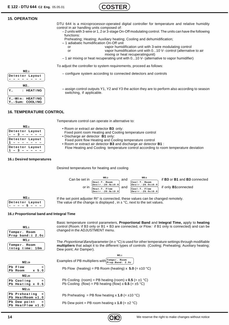
15. OPERATIONDTU 644 is a microprocessor-operated digital controller for temperature and relative humiditycontrol in air handling units composed of:
– 2 units with 3-wire or 1, 2 or 3-stage On-Off modulating control. The units can have the followingfunctions:Preheating; Heating; Auxiliary heating; Cooling and dehumidification;
– 1 adiabatic humidification On-Off unitor vapor humidification unit with 3-wire modulating controlor vapor humidification unit with 0...10 V- control (alternative to air
mixing or heat recuperatingunit)– 1 air mixing or heat recuperating unit with 0...10 V- (alternative to vapor humidifier)
To adjust the controller to system requirements, proceed as follows:
– configure system according to connected detectors and controls
– assign control outputs Y1, Y2 and Y3 the action they are to perform also according to seasonswitching, if applicable.
16. TEMPERATURE CONTROL
Temperature control can operate in alternative to:
• Room or extract air detector B3 only:Fixed point room Heating and Cooling temperature control
• Discharge air detector B1 only:Fixed point flow Heating and Cooling temperature control
• Room or extract air detector B3 and discharge air detector B1 :Flow Heating and Cooling temperature control according to room temperature deviation
16.1 Desired temperatures
Desired temperatures for heating and cooling
Can be set in and if B3 or B1 and B3 connected
or in and if only B1connected
If the set point adjuster Rt° is connected, these values can be changed remotely.The value of the change is displayed , in ± °C, next to the set values.
16.2 Proportional band and Integral Time
Basic temperature control parameters, Proportional Band and Integral Time, apply to heatingcontrol (Room: if B3 only or B1 + B3 are connected, or Flow: if B1 only is connected) and can bechanged in the ADJUSTMENT menu.
The Proportional Band parameter (in ± °C) is used for other temperature settings through modifiablemultipliers that adapt it to the different types of controls (Cooling; Preheating; Auxiliary heating;Dew point; Air Damper).
Examples of PB multipliers with
Pb Flow (heating) = PB Room (heating) x 5.0 (= ±10 °C)
Pb Cooling (room) = PB heating (room) x 0.5 (= ±1 °C)Pb Cooling (flow) = PB heating (flow) x 0.5 (= ±5 °C)
Pb Preheating = PB flow heating x 1.0 (= ±10 °C)
Pb Dew point = PB room heating x 1.0 (= ±2 °C)
Tempe r . RoomP r op . Band : 2 . 0 c
M1.1
De t e c t o r La you t– – – – – – – –
M2.1
De t e c t o r La you t– – 3 – – – – –
M2.1
De t e c t o r La you t1 – – – – – – –De t e c t o r La you t1 – 3 – – – – –
He a t . T . RoomDe s i r . : 2 0 . 0c ±0 . 0
M0.3
He a t . T . F l owDe s i r . : 2 0 . 0c ±0 . 0
Coo l . T . RoomDe s i r . : 2 5 . 0 c ±0 . 0
M0.5
Coo l . T . F l owDe s i r . : 2 5 . 0 c ±0 . 0
De t e c t o r La you t– – – – 5 – – –
M2.1
T empe r . RoomP r op band : ± 2 . 0 c
M1.1
T empe r . RoomI n t eg t ime : 1 0m
M1.2
Pb Coo l i ng =Pb He a t i ng x 0 . 5
M2.20
Pb F l ow =Pb Room x 5 . 0
M2.19
Pb P r ehe a t i ng =Pb He a t Room x 1 . 0
M2.21
Pb Dew po i n t =Pb He a t F l ow x 1 . 0
Y.. : HEAT I NG
M2...
Y.. -Wi n : HEAT I NGY.. - Sum: COOL I NG

15We reserve the right to make changes without notice
COSTER
Pb Air damper = PB room heating x 1.0 (= ±2 °C)
dt recuperator = PB room heating x 1.0 (= 2 °C)
With B3 only :Pb auxiliary heating = PB Room Heatingx 1,0 (= ±2 °C)With B1 and B3 :Pb Auxiliary Heating = Pb Flow Heating x 1.0 (= ±10 °C)
When detectors B1 and B3, are connected, the flow temperature (B1) Integral Time parameter isdisplayed on a display page to allow for changes to be made separately from the room temperatureparameter.
16.3 Control through room detector (B3) only or discharge air detector (B1) only
The controller compares the values and if B3 is used
or and if B1 is used
against the temperature measured by detector B1 or B3, andcalculates the load values for Heating QHea and for CoolingQCoo according to the deviation measured.
16.4 Control through room detector (B3) and discharge air detector (B1)
The controller compares the values and
against the temperature measured by detector B3, and calculates the load values for desired flowtemperatures for Heating T°fHea and for Cooling T°fCoo according to the deviation measured andvalues set:
• Min : – – c Max : – – c = Heating flow temp. minand max values determine the PbHeaproportional band’s range.The minimum value T°fminHea helps eliminateannoying cold drafts in the room. To preventheating and cooling simultaneousness, theminimum value T°fminHea is always 3°C lowerthan Cooling flow temperature T°fCoo.
• Min : – – c Max : – – c = Cooling flow temp. minand max values determine the PbCooproportional band’s range.
The controller compares desired flow temperatures forHeating T°fHea and for Cooling T°fCoo and for CoolingT°fCoo against the temperature measured by the dischargeair detector B1and derives the load values for Heating Qheaand for Cooling Qcoo according to the deviations detected.
To prevent hot air stratification during the Heating stageit is possible to prevent the heating flow temp. T°fHea fromexceeding actual room temperature by more than a certain value.
To prevent condensation in the air duct during the Cooling stage it is possible to prevent thecooling flow temp. T°fCoo from dropping below actual room temperature by more than a certainvalue.
He a t i ng F l owM i n : 1 8 c Ma x : 5 0 c
M1.4
He a t . T . RoomDe s i r . : 2 0 . 0c ±0 . 0
M0.3
Coo l . T . RoomDe s i r . : 2 5 . 0 c ±0 . 0
M0.5
He a t i ngL imi t Ma xF l ow–Room : +1 0 c
M1.5
Coo l i ngL imi t Ma xRoom–F l ow : – 7 c
M1.7
He a t . T . RoomDe s i r . : 2 0 . 0c ±0 . 0
M0.3
He a t . T . F l owDe s i r . : 2 0 . 0c ±0 . 0
Coo l . T . RoomDe s i r . : 2 5 . 0 c ±0 . 0
M0.5
He a t . T . F l owDe s i r . : 2 5 . 0 c ±0 . 0
Pb Dampe r s =Pb He a t Room x 1 . 0
M2.22
d t Re cupe r a t o r =Pb He a t Room x 1 . 0
Pb Aux he a t i ng =Pb He a t Room x 1 . 0
M2.23
Pb Aux he a t i ng=Pb He a t F l ow x 1 . 0
F l ow Temperat u r eI n t eg r . T ime : 1 0m
M1.3
Coo l i ng F l owM i n : 8 c Ma x : 2 5 c
M1.6
0%
100%
Q
T°Hea
PbHea
50%
– + t°T°Coo
PbCoo
QHea QCoo
t°r+
T°fmaxHea
T°f
–
PbHea PbCoo
T°fHea
T°fCoo
T°fminRis
T°rHea T°rCoo
T°fLimHea = t°r + ∆t°hea
T°fminCoo
T°fmaxCoo
T°fLimCoo = t°r – ∆t°coo
T°fminHea = T°fCoo – 3 °C
0%
100%
Q
T°fHea
PbfHea
50%
– + t°fT°fCoo
PbfCoo
QHea QCoo
16
E 122 - DTU 644 C2 Eng. 05.05.01
We reserve the right to make changes without notice
COSTER
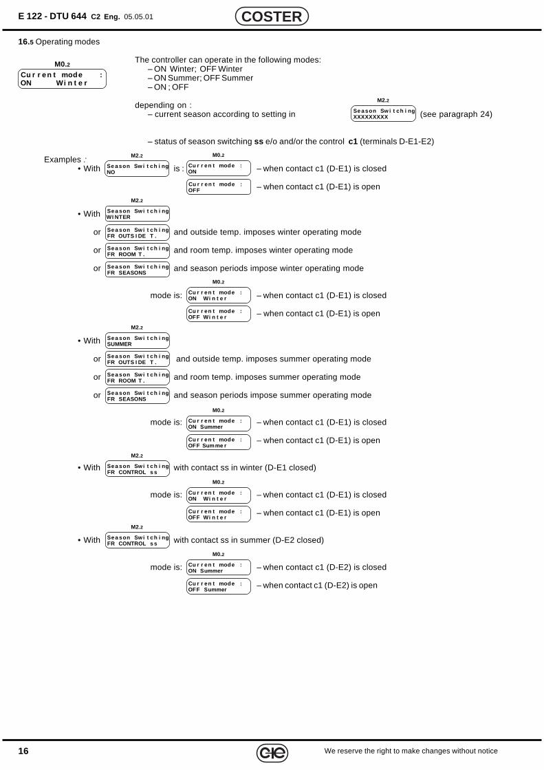
16.5 Operating modes
The controller can operate in the following modes:– ON Winter; OFF Winter– ON Summer; OFF Summer– ON ; OFF
depending on :– current season according to setting in (see paragraph 24)
– status of season switching ss e/o and/or the control c1 (terminals D-E1-E2)
Examples :• With is : – when contact c1 (D-E1) is closed
– when contact c1 (D-E1) is open
• With
or and outside temp. imposes winter operating mode
or and room temp. imposes winter operating mode
or and season periods impose winter operating mode
mode is: – when contact c1 (D-E1) is closed
– when contact c1 (D-E1) is open
• With
or and outside temp. imposes summer operating mode
or and room temp. imposes summer operating mode
or and season periods impose summer operating mode
mode is: – when contact c1 (D-E1) is closed
– when contact c1 (D-E1) is open
• With with contact ss in winter (D-E1 closed)
mode is: – when contact c1 (D-E1) is closed
– when contact c1 (D-E1) is open
• With with contact ss in summer (D-E2 closed)
mode is: – when contact c1 (D-E2) is closed
– when contact c1 (D-E2) is open
Cu r r en t mode :ON Wi n t e r
M0.2
Se a son Sw i t ch i ngXXXXXXXXX
M2.2
Se a son Sw i t ch i ngNO
M2.2
Cu r r en t mode :ON
M0.2
Cu r r en t mode :OFF
Se a son Sw i t c h i ngWI NTER
M2.2
Cu r r en t mode :ON Wi n t e r
M0.2
Cu r r en t mode :OFF Wi n t e r
Cu r r en t mode :ON Summer
M0.2
Cu r r en t mode :OFF Summe r
Se a son Sw i t c h i ngFR OUTS I DE T .
Se a son Sw i t c h i ngFR ROOM T .
Se a son Sw i t c h i ngFR SEASONS
Se a son Sw i t c h i ngSUMMER
M2.2
Se a son Sw i t c h i ngFR OUTS I DE T .
Se a son Sw i t c h i ngFR ROOM T .
Se a son Sw i t c h i ngFR SEASONS
Cu r r en t mode :ON Wi n t e r
M0.2
Cu r r en t mode :OFF Wi n t e r
Se a son Sw i t c h i ngFR CONTROL s s
M2.2
Se a son Sw i t c h i ngFR CONTROL s s
M2.2
Cu r r en t mode :ON Summer
M0.2
Cu r r en t mode :OFF Summer
17We reserve the right to make changes without notice
COSTER
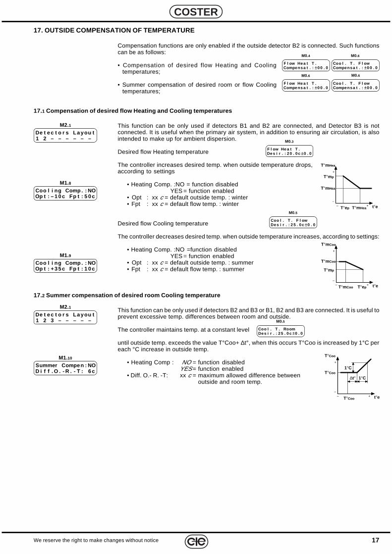
17. OUTSIDE COMPENSATION OF TEMPERATURE
Compensation functions are only enabled if the outside detector B2 is connected. Such functionscan be as follows:
• Compensation of desired flow Heating and Coolingtemperatures;
• Summer compensation of desired room or flow Coolingtemperatures;
17.1 Compensation of desired flow Heating and Cooling temperatures
This function can be only used if detectors B1 and B2 are connected, and Detector B3 is notconnected. It is useful when the primary air system, in addition to ensuring air circulation, is alsointended to make up for ambient dispersion.
Desired flow Heating temperature
The controller increases desired temp. when outside temperature drops,according to settings
• Heating Comp. :NO = function disabledYES = function enabled
• Opt : xx c = default outside temp. : winter• Fpt : xx c = default flow temp. : winter
Desired flow Cooling temperature
The controller decreases desired temp. when outside temperature increases, according to settings:
• Heating Comp. :NO =function disabledYES = function enabled
• Opt : xx c = default outside temp. : summer• Fpt : xx c = default flow temp. : summer
17.2 Summer compensation of desired room Cooling temperature
This function can be only used if detectors B2 and B3 or B1, B2 and B3 are connected. It is useful toprevent excessive temp. differences between room and outside.
The controller maintains temp. at a constant level
until outside temp. exceeds the value T°Coo+ ∆t°, when this occurs T°Coo is increased by 1°C pereach °C increase in outside temp.
• Heating Comp : NO = function disabledYES = function enabled
• Diff. O.- R. -T: xx c = maximum allowed difference betweenoutside and room temp.
Coo l . T . RoomDe s i r . : 2 5 . 0 c ±0 . 0
M0.5
Summer Compen : NOD i f f . O . - R . - T : 6 c
M1.10
Coo l i ng Comp . : NOOp t : +3 5 c Fp t : 1 0 c
M1.9
De t e c t o r s La you t1 2 3 – – – – –
M2.1
Coo l . T . F l owDe s i r . : 2 5 . 0 c ±0 . 0
M0.5
Coo l i ng Comp . : NOOp t : – 1 0 c Fp t : 5 0 c
M1.8
De t e c t o r s La you t1 2 – – – – – –
M2.1
F l ow He a t T .De s i r . : 2 0 . 0 c ±0 . 0
M0.3
F l ow He a t T .Compens a t . : ±0 0 . 0
M0.4
Coo l . T . F l owCompens a t . : ±0 0 . 0
M0.6
Coo l . T . F l owCompens a t . : ±0 0 . 0
M0.6
F l ow He a t T .Compe ns a t . : ±0 0 . 0
M0.6
–+–
+
T°mHea
t°e
T°mHea
T°mHea
T°mp
T°ep
–+–
+
T°mCoo
t°e
T°mCoo
T°mCoo
T°mp
T°ep
–+–
+
T°Coo
t°e
T°Coo
T°Coo
∆t° 1°C
1°C
18
E 122 - DTU 644 C2 Eng. 05.05.01
We reserve the right to make changes without notice
COSTER
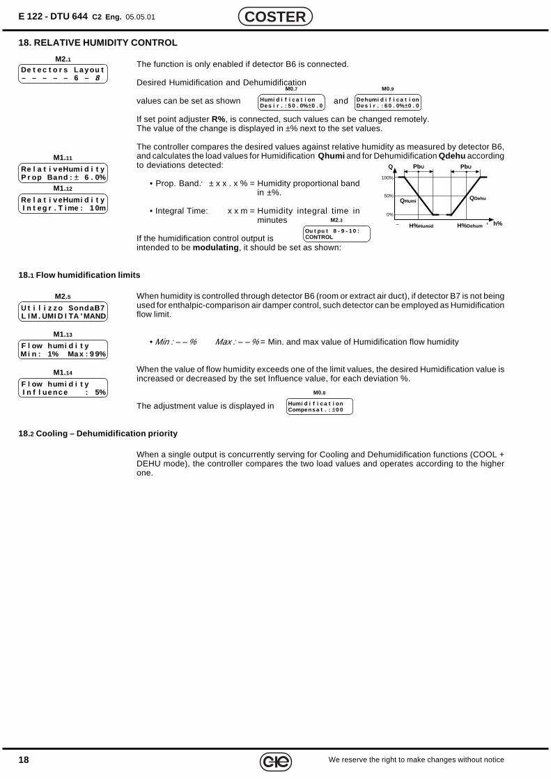
18. RELATIVE HUMIDITY CONTROL
The function is only enabled if detector B6 is connected.
Desired Humidification and Dehumidification
values can be set as shown and
If set point adjuster R%, is connected, such values can be changed remotely.The value of the change is displayed in ±% next to the set values.
The controller compares the desired values against relative humidity as measured by detector B6,and calculates the load values for Humidification Qhumi and for Dehumidification Qdehu accordingto deviations detected:
• Prop. Band: ± x x . x % = Humidity proportional bandin ±%.
• Integral Time: x x m = Humidity integral time inminutes
If the humidification control output isintended to be modulating , it should be set as shown:
18.1 Flow humidification limits
When humidity is controlled through detector B6 (room or extract air duct), if detector B7 is not beingused for enthalpic-comparison air damper control, such detector can be employed as Humidificationflow limit.
• Min : – – % Max : – – % = Min. and max value of Humidification flow humidity
When the value of flow humidity exceeds one of the limit values, the desired Humidification value isincreased or decreased by the set Influence value, for each deviation %.
The adjustment value is displayed in
18.2 Cooling – Dehumidification priority
When a single output is concurrently serving for Cooling and Dehumidification functions (COOL +DEHU mode), the controller compares the two load values and operates according to the higherone.
Humi d i f i c a t i onDe s i r . : 5 0 . 0% ±0 . 0
M0.7
Dehumi d i f i c a t i onDe s i r . : 6 0 . 0% ±0 . 0
M0.9
Re l a t i v eHumi d i t yP r op Band : ± 6 . 0%
M1.11
Re l a t i v eHumi d i t yI n t eg r . T ime : 1 0m
M1.12
De t e c t o r s La you t– – – – – 6 – 8
M2.1
Ou t pu t 8 - 9 - 1 0 :CONTROL
M2.3
U t i l i z z o SondaB7L I M . UMI D I TA ' MAND
M2.5
F l ow humi d i t yM i n : 1% Ma x : 9 9%
M1.13
F l ow humi d i t yI n f l uenc e : 5%
M1.14
Humi d i f i c a t i onCompens a t . : ±0 0
M0.8
0%
100%
Q
H%Humid
PbU
50%
– + h%H%Dehum
PbU
QHumi QDehu
19We reserve the right to make changes without notice
COSTER
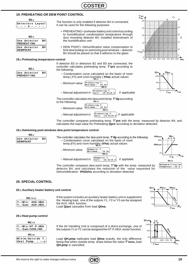
19. PREHEATING OR DEW POINT CONTROL
The function is only enabled if detector B4 is connected.It can be used for the following purposes:
• PREHEATING = preheater battery unit control accordingto humidification condensation temperature throughduct mounting detector B4, installed downstream ofthe humidification unit.
• DEW POINT= Dehumification value compensation tolimit dew buildup on swimming pool windows – detectorB4 should be placed so that it adheres to the glass
19.1 Preheating temperature controlIf detector B3 or detectors B1 and B3 are connected, thecontroller calculates preheating temp. T°pre according tothe following:
– Condensation curve calculated on the basis of roomtemp.( t°r) and room humidity ( h%a) actual values
– Minimum value
– Manual adjustment in if applicable
The controller calculates the dew point temp. T°dp accordingto the following:
– Minimum value
– Manual adjustment in if applicable
The controller compares preheating temp. T°pre with the temp. measured by detector B4, andcalculates the load value for Preheating Qpre according to deviation detected.
19.2 Swimming pool windows dew point temperature control
The controller calculates the dew point temp. T°dp according to the following:– Condensation curve calculated on the basis of room
temp.(t°r) and room humidity (h%a) actual values
– Minimum value
– Manual adjustment in if appliable
The controller compares dew point temp. T°dp with the temp. measured bydetector B4, and calculates the reduction of the value requested forDehumidification H%Dehu according to deviation detected.
P r ehe a t i ng T .M i n imum : 1 0 . 0c
M0.11
Dewpo i n t T .M i n imum : 1 0 . 0c
M0.11
P r ehe a t i ng T .Ca l c . : 1 6 . 0 c ±0 . 0
M0.12
Dewpo i n t T .Ca l c . : 1 6 . 0 c ±0 . 0
M0.12
De humi d i f i c a t i onCompens a t . : ±0 . 0
M0.10
De t e c t o r s La you t– – – 4 – – – –
M2.1
20. SPECIAL CONTROL
20.1 Auxiliary heater battery unit control
If the system includes an auxiliary heater battery unit to supplementthe Heating load, one of the outputs Y1, Y2 or Y3 can be assignedthe AUX. HEA. function.Load Qaux cascades from load Qhea.
20.2 Heat pump control
If the Air Handling Unit is composed of a direct-exchange, one ofthe outputs Y1 or Y2 can be assigned the HT.P.HEA. winter function.
Load QH.pmp replicates load Qhea exactly, the only differencebeing that when outside temp. drops below the value T°omin, loadQH.pmp is cancelled.
Y.. -Wi n : HT . P . HEAY.. - Sum: COOL I NG
M2.7.9
Y.. -Wi n : AUX . HEA .Y.. - Sum: AUX . HEA .
M2.7.9.11
M1.19
M i n im. Ou t s i de T .He a t Pump : – – c
P r ehe a t i ng T .M i n imum : 1 0 . 0c
M0.11
P r ehe a t i ng T .Ca l c . : 1 6 . 0 c ±0 . 0
M0.12
Us e de t e c t o r B4PREHEAT I NG
M2.4
M2.4
Us e de t e c t o r B4DEWPOI NT
Us e de t e c t o r B4PREHEAT I NG
M2.4
Us e de t e c t o r B4DEWPOI NT
T°pre– +
0%
100%
50%
QPre
t°pre
Pbpre
– +
0%
100%
H%Deum
t°dp
Bprv
T°dp
H%Deum
0%
100%
T°Hea
PbAux
50%
– + t°
QHea
PbHeaQAux
0%
100%
50%
– + t°o
1°C
T°omin
QHea
QH.pmp
50%100% 0%
QHea
T°preT°dp
25°
15°
5°
20°
10°
30°
20% 30% 40% 50% 60% 70% 80% 90% h%r
t°r
6°
10°
15°
20°
25°
30°35°
t°r
T°min
20
E 122 - DTU 644 C2 Eng. 05.05.01
We reserve the right to make changes without notice
COSTER
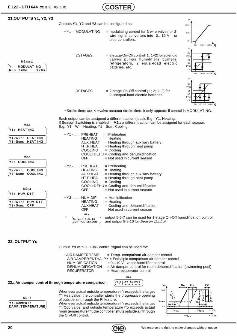
22. OUTPUT YsOutput Ys with 0...10V– control signal can be used for:
• AIR DAMPER TEMP. = Temp. comparison air damper controlAIR DAMPER ENTHALPY = Enthalpic comparison air damper control .HUMIDIFICATION = 0…10 V– vapor humidifier control.DEHUMIDIFICATION = Air damper control for room dehumidification (swimming pool)RECUPERATOR = Heat recuperator control
22.1 Air damper control through temperature comparison
Whenever actual outside temperature t°r exceeds the targetT°rHea value, the controller starts the progressive openingof outside air through the PI feature.Whenever actual outside temperature t°r exceeds the targetT°rCoo value, and outside temperature t°o exceeds actualroom temperature t°r, the controller shuts outside air throughthe On-Off control.
Ys - Contr o l :DAMP. TEMPERATURE
M2.12
De t e c t o r La y ou t– 2 3 – – – – –
M2.1
21.OUTPUTS Y1, Y2, Y3Outputs Y1, Y2 and Y3 can be configured as:
• Y.. - MODULATING = modulating control for 3-wire valves or 3-wire signal converters into 0…10 V – orstep controllers.
2 STAGES = 2-stage On-Off control (1 ; 1+2) for solenoidvalves, pumps, humidifiers, burners,refrigerators, 2 equal-load electricbatteries, etc.
3 STAGES = 2-stage On-Off control (1 ; 2; 1+2) for2 unequal-load electric batteries.
• Stroke time: xxx s = valve actuator stroke time. It only appears if control is MODULATING.
Each output can be assigned a different action (load). E.g.: Y1: Heating.If Season Switching is enabled in M2.2 a different action can be assigned for each season.E.g.: Y1 – Win: Heating; Y1 – Sum: Cooling.
• Y1 - .....: PREHEAT. = PreheatingHEATING = HeatingAUX. HEAT = Heating through auxiliary batteryHT.P.HEA. = Heating through heat pumpCOOLING = CoolingCOOL+DEHU = Cooling and dehumidificationOFF = Not used in current season
• Y2 - .....: PREHEAT. = PreheatingHEATING = HeatingAUX HEAT = Heating through auxiliary batteryHT.P.HEA. = Heating through heat pumpCOOLING = CoolingCOOL+DEHU = Cooling and dehumidificationOFF = Not used in current season
• Y3 - .....: HUMIDIF. = HumidificationHEATING = HeatingAUX HEAT = Cooling and dehumidificationOFF = Not used in current season
If output 5-6-7 can be used for 1-stage On-Off humidification control,and output 8-9-10 for Season Control.
Y.. - MODULAT I NGRun t ime : 1 2 0 s
M2.6.8.10
Ou t pu t 8 - 9 - 1 0CONTROL SEASON
M2.3
100%
50%
0% Q
0%
Y
100%50%
Y1 : HEAT I NG
M2.7
Y1 -Wi n : HEAT I NGY1 - Sum: HEAT I NG
Y2 : COOL I NG
M2.9
Y2 -Wi n : COOL I NGY2 - Sum: COOL I NG
Y3 : HUMI D I F .
M2.11
Y3 -Wi n : HUMI D I F .Y3 - Sum: OFF
0% Q
Y
100%50%
Off
OffOn
On
1stSt
2ndSt
0% Q
Y
100%1/3
Off
OffOn
On
1stSt
2ndSt
2/3
t°o
= t°
r
t°a+
0 V
10 V
–
t°o
< t°
r
1°CYs Pbs
T°rHea T°rCoo
QH
ea
QC
oo
Ysmin
t°m+– T°fmin
Pbs
MsR MsR
21We reserve the right to make changes without notice
COSTER
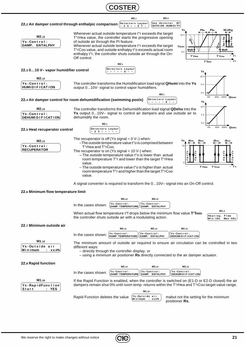
22.2 Air damper control through enthalpic comparison
Whenever actual outside temperature t°r exceeds the targetT°rHea value, the controller starts the progressive openingof outside air through the PI feature.Whenever actual outside temperature t°r exceeds the targetT°rCoo value, and outside enthalpy t°o exceeds actual roomenthalpy t°r, the controller shuts outside air through the On-Off control.
22.3 0…10 V– vapor humidifier control
The controller transforms the Humidification load signal QHumi into the Ysoutput 0...10V- signal to control vapor humidifiers.
22.4 Air damper control for room dehumidification (swimming pools)
The controller transforms the Dehumidification load signal QDehu into theYs output 0...10V– signal to control air dampers and use outside air todehumidify the room.
22.5 Heat recuperator control
The recuperator is off (Ys signal = 0 V–) when:–The outside temperature value t°o is comprised between
T°rhea and T°rCoo.The recuperator is on (Ys signal = 10 V-) when:
– The outside temperature value t°o is lower than actualroom temperature T°r and lower than the target T°rHeavalue.
– The outside temperature value t°o is higher than actualroom temperature T°r and higher than the target T°rCoovalue.
A signal converter is required to transform the 0...10V– signal into an On-Off control.
22.6 Minimum flow temperature limit
In the cases shown:
When actual flow temperature t°f drops below the minimum flow value T°fminthe controller shuts outside air with a modulating action.
22.7 Minimum outside air
In the cases shown:
The minimum amount of outside air required to ensure air circulation can be controlled in twodifferent ways:
– directly through the controller display, or– using a minimum air positioner Rs directly connected to the air damper actuator.
22.8 Rapid function
In the cases shown:
If the Rapid Function is enabled, when the controller is switched on (E1-D or E2-D closed) the airdampers remain shut 0% until room temp. returns within the T°rHea and T°rCoo target value range.
Rapid Function deletes the value mabut not the setting for the minimumpositioner Rs.
Ys - Con t r o l :RECUPERATOR
M2.12
Ys - Con t r o l :DEHUMI D I F I CAT I ON
M2.12
Ys - Ou t s i de a i rM i n imum : x x x %
M1.15
Ys - Rap i dFunc t i onS t a r t : YES
M1.16
Ys - Con t r o l :DAMP. TEMPERATURE
M2.12
Ys - Con t r o l :DAMP. ENTALPHY
M2.12
Ys - Con t r o l :DAMP. TEMPERATURE
M2.12
Ys - Con t r o l :DAMP. ENTALPHY
M2.12
Ys - Con t r o l :DEHUMI D I F I CAT I ON
M2.12
Ys - Ou t s i de a i rM i n imum : x x x%
M1.15
De t e c t o r s La you t– 2 3 – – 6 7 –
M2.1
De t e c t o r s La you t– – – – – 6 – –
M2.1
De t e c t o r s La you t– 2 3 – – – – –
M2.1
Ys - Con t r o l :DAMP. TEMPERATURE
M2.12
Ys - Con t r o l :DAMP. ENTALPHY
M2.12
Ys - Con t r o l :DEHUMI D I F I CAT I ON
M2.12
He a t i ng . F l owM i n : 1 8 c Ma x : 5 0c
M1.4
Ys - Con t r o l :DAMP. ENTALPHY
M2.12
Us e de t e c t o r B7OUTS I DE HUMI D I TY
M2.5
Ys - Con t r o l :HUMI D I F I CAT I ON
M2.12
De t e c t o r s La you t– – – – – 6 – –
M2.1
10 V.
5 V.
0% QDehu
0 V.
Ys
100%50%
10 V.
5 V.
0% QHumi
0 V.
Ys
100%50%
he =
ha
t°r+
0 V
10 V
–
he <
ha
5KJ/KgYs Pbs
T°rHea T°rCooQ
Hea
QC
oo
Ysmin
t°f+– T°fmin
Pbs
MsR MsR
t°o
= t°
r
t°o+
0
10
–
t°o
> t°
r
Ys
T°rHea T°rCoo
t°o
= t°
r
t°o
< t°
r
dt rec dt recdt rec dt rec
22
E 122 - DTU 644 C2 Eng. 05.05.01
We reserve the right to make changes without notice
COSTER
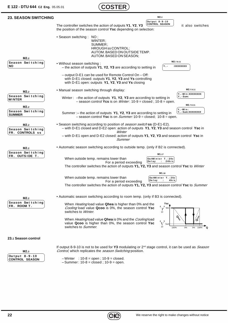
23. SEASON SWITCHING
The controller switches the action of outputs Y1, Y2, Y3 it also switchesthe position of the season control Ysc depending on selection:
• Season switching : NO ;WINTER ;SUMMER ;HROUGH ss CONTROL;AUTOM. BASED ON OUTSIDE TEMP.AUTOM. BASED ON SEASON;
• Without season switching :– the action of outputs Y1, Y2, Y3 are according to setting in
– output D-E1 can be used for Remote Control On – Off:with D-E1 closed: outputs Y1, Y2, Y3 and Ys controllingwith D-E1 open: outputs Y1, Y2, Y3 and Ys closing
• Manual season switching through display:
Winter : –the action of outputs Y1, Y2, Y3 are according to setting in– season control Ycs is on Winter : 10-9 = closed ; 10-8 = open.
Summer :– the action of outputs Y1, Y2, Y3 are according to setting in– season control Ysc is on Summer: 10-9 = closed; 10-8 = open.
• Season switching according to position of season switch ss (D-E1-E2).– with D-E1 closed and D-E2 open: action of outputs Y1, Y2, Y3 and season control Ysc in
Winter– with D-E1 open and D-E2 closed: action of outputs Y1, Y2, Y3 and season control Ysc in
Summer
• Automatic season switching according to outside temp. (only if B2 is connected).
When outside temp. remains lower thanFor a period exceeding
The controller switches the action of outputs Y1, Y2, Y3 and season control Ysc to Winter
When outside temp. remains lower thanFor a period exceeding
The controller switches the action of outputs Y1, Y2, Y3 and season control Ysc to Summer
• Automatic season switching according to room temp. (only if B3 is connected).
When Heating load value Qhea is higher than 0% and theCooling load value Qcoo is 0%, the season control Yscswitches to Winter.
When Heating load value Qhea is 0% and the Cooling loadvalue Qcoo is higher than 0%, the season control Yscswitches to Summer.
23.1 Season control
If output 8-9-10 is not to be used for Y3 modulating or 2nd stage control, it can be used as SeasonControl, which replicates the season Switching position.
– Winter : 10-8 = open ; 10-9 = closed.– Summer : 10-8 = closed ; 10-9 = open.
Se a son Sw i t ch i ngFR . OUTS I DE T .
M2.2
Ou tWi n t e r T . : 2 0cDe l a y : 2 4h r s
M1.17
Ou tWi n t e r T . : 2 5cDe l a y : 4h r s
M1.18
Se a son Sw i t ch i ngNO
M2.2
Se a son Sw i t ch i ngWI NTER
M2.2Y.. -Wi n :XXXXXXXXY.. - Sum:
M2.7.9.11
Se a son Sw i t ch i ngSUMMER
M2.2Y.. -Wi n :Y.. - Sum:XXXXXXXX
M2.7.9.11
Se a son Sw i t ch i ngFR . CONTROLS s s
M2.2
Y.. - :XXXXXXXX
M2.7.9.11
Se a son Sw i t ch i ngFR . ROOM T .
M2.2
Ou t pu t 8 - 9 - 1 0CONTROL SEASON
M2.3
M2.3
Ou t pu t 8 - 9 - 1 0CONTROL SEASON
Q
Sum
Win
Ysc
QHea
QC
oo
0% 100%0%100%
10
98
10
98
23We reserve the right to make changes without notice
COSTER
24. COMPLEMENTARY FUNCTIONS
24.1 PasswordPassword selection and enabling. The command disables the use of keys + and –, so that datacannot be modified. Enter the number (1900... 1999) using the + and – keys. To delete passwordpress + and – simultaneously until the dashes reappear.
If the + or – key is pressed when the password is enabled, the display will show a request to enter thepassword. The + and – keys can only be used after entering the proper password. If no key ispressed in the next 15 minutes, the password will be automatically re-enabled.
24.2 Site name
Site name as it appears on the first display page.Each dash can be replaced with a letter (A...Z) or a number (0...9), using the + and – keys. The →key is used to position the cursor.
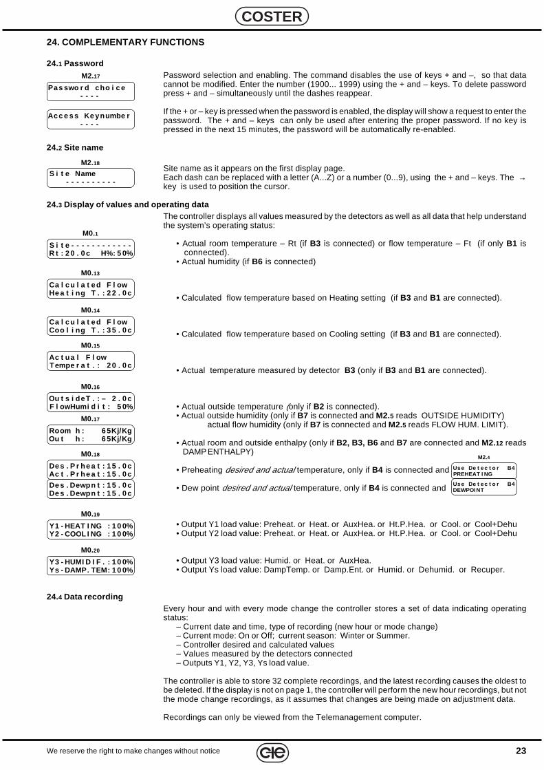
24.3 Display of values and operating dataThe controller displays all values measured by the detectors as well as all data that help understandthe system’s operating status:
• Actual room temperature – Rt (if B3 is connected) or flow temperature – Ft (if only B1 isconnected).
• Actual humidity (if B6 is connected)
• Calculated flow temperature based on Heating setting (if B3 and B1 are connected).
• Calculated flow temperature based on Cooling setting (if B3 and B1 are connected).
• Actual temperature measured by detector B3 (only if B3 and B1 are connected).
• Actual outside temperature (only if B2 is connected).• Actual outside humidity (only if B7 is connected and M2.5 reads OUTSIDE HUMIDITY)
actual flow humidity (only if B7 is connected and M2.5 reads FLOW HUM. LIMIT).
• Actual room and outside enthalpy (only if B2, B3, B6 and B7 are connected and M2.12 readsDAMP ENTHALPY)
• Preheating desired and actual temperature, only if B4 is connected and
• Dew point desired and actual temperature, only if B4 is connected and
• Output Y1 load value: Preheat. or Heat. or AuxHea. or Ht.P.Hea. or Cool. or Cool+Dehu• Output Y2 load value: Preheat. or Heat. or AuxHea. or Ht.P.Hea. or Cool. or Cool+Dehu
• Output Y3 load value: Humid. or Heat. or AuxHea.• Output Ys load value: DampTemp. or Damp.Ent. or Humid. or Dehumid. or Recuper.
24.4 Data recordingEvery hour and with every mode change the controller stores a set of data indicating operatingstatus:
– Current date and time, type of recording (new hour or mode change)– Current mode: On or Off; current season: Winter or Summer.– Controller desired and calculated values– Values measured by the detectors connected– Outputs Y1, Y2, Y3, Ys load value.
The controller is able to store 32 complete recordings, and the latest recording causes the oldest tobe deleted. If the display is not on page 1, the controller will perform the new hour recordings, but notthe mode change recordings, as it assumes that changes are being made on adjustment data.
Recordings can only be viewed from the Telemanagement computer.
M2.17
Pas swo r d cho i c e- - - -
M2.18
S i t e Name- - - - - - - - - -
Acc e s s Ke ynumbe r- - - -
M0.1
S i t e - - - - - - - - - - - -R t : 2 0 . 0 c H%: 5 0%
M0.13
Ca l cu l a t ed F l owHe a t i ng T . : 2 2 . 0 c
M0.16
Ou t s i deT . : – 2 . 0 cF l owHumi d i t : 5 0%
M0.19
Y1 - HEAT I NG : 1 0 0%Y2 - COOL I NG : 1 0 0%
M0.20
Y3 - HUMI D I F . : 1 0 0%Ys - DAMP. TEM: 1 0 0%
M0.14
Ca l cu l a t ed F l owCoo l i ng T . : 3 5 . 0 c
M0.15
Ac t ua l F l owTempe r a t . : 2 0 . 0 c
M0.17
Room h : 6 5Kj/KgOu t h : 6 5Kj/Kg
M0.18
De s . P r he a t : 1 5 . 0 cAc t . P r he a t : 1 5 . 0 c
De s . Dewpn t : 1 5 . 0 cDe s . Dewpn t : 1 5 . 0 c
Us e De t e c t o r B4PREHEAT I NG
M2.4
Us e De t e c t o r B4DEWPOI NT
24
E 122 - DTU 644 C2 Eng. 05.05.01
We reserve the right to make changes without notice
COSTER
26. SYSTEM STARTUP TESTThe test must be carried out once installation is completed and the wiring and configuration havebeen executed and checked.
Using the + and – keys, select:• output to be tested:
– Y1 MODUL. or Y1 2 STADGES or Y1 3 STADGES : depending on M2.6 setting .– Y2 MODUL. or Y2 2 STADGES orY2 3 STADGES : depending on M2.8 setting .– Y3 MODUL. or Y3 2 STADGES or Y3 3 STADGES : depending on M2.10, setting, or
Y3 ON-OFF : if in M2.3 setting is SEASON CONTROL– Ycs ; appears if M2.3 setting is SEASON CONTROL– Ys ;
• status :– with Y...MODUL. : STOPS; OPENS; CLOSES– with Y.. 2 STAGES: ON 1; ON 1+2; OFF– with Y.. 3 STAGES: ON 1; ON 2; ON 1+2; OFF– with Y3 ON-OFF : ON ; OFF.– with Ycs : WINTER; SUMMER– with Ys : 0 VOLT ; 5 VOLT ; 10 VOLT.
Check results.
M3.1
Ou t pu t : Y1 MODUL.S t a t us : I DLE
25. ALARMS
The controller processes two types of alarms:– alarms related to functional irregularities affecting the controller (LED 6.9) and the controlledsystems (LED 6.8)– alarms related to short and open detector circuits (LED 6.8)
Alarms are signaled by LEDs located on the controller’s front panel and by the word ALARMappearing on the display when the alarm is transmitted to the PC. On the display page alarms areidentified by a letter “A” flashing alternately to the number corresponding to the relevant alarm.
Alarms can be transmitted to a local and/or a central telemanagement computer through the C-Busconnection.
25.1 Functional alarms
Functional alarms occur when there is a continuing deviation between actual and desired measures.These alarms do not affect the controller’s proper operation.Non pregiudicano il regolare funzionamento del regolatoreBy default” all alarms are disabled except clock alarm (8)Use the + and – keys to enable desired alarms, entering numbers in place of the dashes.Number flashing = the alarm is onAlarm limit values and delays can only be changed via computer.
Types and reasons of alarms:1 = flow temperature difference (if only B1 is connected)
– for actual temp. lower than T°fHea when Y..: Heatingor higher than T°fCoo when Y..: Cooling
3 = room temperature difference (if B3 is connected) – for actual temp. lower than T°rHea when Y..: Heating
or higher than T°rCoo when Y..: Cooling4 = preheating or dew point temperature difference (if B4 is connected)
– for actual temp. lower than desired value6 = humidity difference (B6)
– for actual humidity lower than H%Humi when Y..: Humidificationor higher than H%Hehu when Y..: Dehumidification
8 = internal clock cannot be disabled– when the clock assumes inconsistent values
25.2 Detector alarms
Detector alarms occur when there is a short circuit or open circuit affecting the connecteddetectors.The effect of alarm situations is delayed by one minute."By default” all alarms are disabled.Use the + and – keys to enable desired alarms, entering numbers in place of the dashes.
Types and effects of alarms:1 = flow temp. detector ( B1): valve stops where it is2 = outside temp. detector ( B2): valve stops where it is3 = room temp. detector ( B3): valve stops where it is4 = preheating temp. detector ( B4): valve stops where it is
dew point detector ( B4): action cancelled
M2.15
A l a rm Func t i ons– – – – 8
M2.16
A l a rms De t e c t o r– – – –
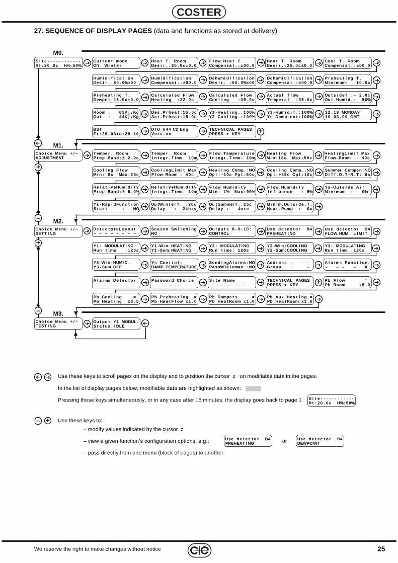
25We reserve the right to make changes without notice
COSTER
Use these keys to scroll pages on the display and to position the cursor z on modifiable data in the pages.
In the list of display pages below, modifiable data are highlighted as shown:
Pressing these keys simultaneously, or in any case after 15 minutes, the display goes back to page 1
Use these keys to:
– modify values indicated by the cursor z
– view a given function’s configuration options, e.g.: or
– pass directly from one menu (block of pages) to another
Us e de t e c t o r B4PREHEAT I NG
Us e de t e c t o r B4DEWPOI NT
S i t e - - - - - - - - - - - -R t : 2 0 . 0 c H%: 5 0%
– +
27. SEQUENCE OF DISPLAY PAGES (data and functions as stored at delivery)
He a t T . RoomDe s i r . : 2 0 . 0 c ±0 . 0
He a t T . RoomDe s i r . : 2 5 . 0 c ±0 . 0
–
+
F l ow He a t T .Compens a t . : ±0 0 . 0
Coo l T . RoomCompens a t . : ±0 0 . 0
Tempe r . RoomP r op Band : ± 2 . 0c
Tempe r . RoomI n t eg r . T ime : 1 0m
He a t i ngL im i t MaxF l ow - Room : 4 0c
Coo l i ng F l owM i n : 8 c Ma x : 2 5c
Coo l i ngL im i t MaxF l ow - Room : 4 0 c
Cho i c e Menu + / –ADJUSTMENT
M1.
Summer Compe n : NOD i f f . O . T–R . T : 6c
Re l a t i v eHumi d i t yP r op Band : ± 6 . 0%
He a t i ng Comp . : NOOp t : – 1 0 c Fp t : 5 0c
Coo l i ng Comp . : NOOp t : +3 5 c Op t : 1 0c
De t e c t o rs L a y ou t– – – – – – – –
Cho i c e Menu + / –SETT I NG
M2.
Ou t pu t : Y1 MODUL.S t a t us : I DLE
Cho i c e Menu + / –TEST I NG
M3.–
+
Se a son Sw i t ch i ngNO
Ou t pu t s 8 - 9 - 1 0 :CONTROL
Cu r r en t modeON Wi n t e r
F l ow Tempe r a t u r eI n t eg r . T ime : 1 0m
S i t e - - - - - - - - - - - -R t : 2 0 . 0 c H%: 5 0%
M0.
TECHN I CAL PAGESPRESS + KEY +DTU 6 4 4 C2 Eng
Ve r s . x xBSTF r : 2 6 . 0 3 t o : 2 8 . 10
1 2 . 1 8 MONDAY1 0 . 0 3 . 0 0 GMT
Y3 - Humi d i f . : 1 0 0%Ys - Damp . en t : 1 0 0%
Y1 - He a t i ng . : 1 0 0%Y2 - Coo l i ng . : 1 0 0%
De s . P r he a t : 1 5 . 0cAc t . P r he a t : 1 5 . 0c
Room : 6 5K j / KgOu t : 4 4K j / Kg
Ou t s i deT . : – 2 . 0cOu t . Humi d . : 5 0%
Ac t ua l f l owTempe r a t : 3 5 . 0 c
Ca l cu l a t ed F l owCoo l i ng : 3 5 . 0c
Ca l cu l a t ed F l owHe a t i ng : 2 2 . 0 c
P r e he a t i ng T .Dewpn t : 1 6 . 0 c ±0 . 0
P r e he a t i ng T .M i n imum: 1 0 . 0c
Dehumi d i f i c a t i onCompens a t . : ±0 0 . 0
Dehumi d i f i c a t i onDe s i r . : 6 0 . 0% ±00
Humi d i f i c a t i onDe s i r . : 5 0 . 0% ±0 0
Humi d i f i c a t i onCompens a t . : ±0 0 . 0
M i n im. Ou t s i de . T .He a t . Pump : 0 c
Ou t Summer T . : 2 5 cDe l a y : 4o r e
Ou tWi n t e r T . : 2 0cDe l a y : 2 4 h r s
Ys - Rap i dFunc t i onS t a r t : NO
Ys - Ou t s i de A i rM i n imum : 0%
Re l a t i v eHumi d i t yI n t eg r . T ime: 1 0m
He a t i ng F l owM i n : 1 8 c Ma x : 5 0c
F l ow Humi d i t yM i n : 1% Ma x : 9 9%
F l ow Humi d i t yI n f l uenc e : 5%
Pb Aux He a t i ng =Pb He a t Room x 1 . 0
Pb Dampe r s =Pb He a t Room x 1 . 0
Pb P r ehe a t i ng =Pb He a t F l ow x 1 . 0
Pb Coo l i ng =Pb He a t i ng x 0 . 5
Pb F l ow =Pb Room x 5 . 0+TECHN I CAL PAGES
PRESS + KEYS i t e Name
- - - - - - - - - -Pa s swo r d Cho i c e
- - - -A l a rms De t e c t o r– – – –
A l a rms Func t i on .– – – – 8
Add r e s s : - - -Gr oup : -
Send i ngA l a rms : NOPa s sWTe l eman : NO
Ys - Con t r o l :DAMP. TEMPERATURE
Y3 -Wi n : HUMI D .Y3 - Sum: OFF
Y3 : MODULAT I NGRun t ime : 1 2 0 s
Y2 -Wi n : COOL I NGY2 - Sum: COOL I NG
Y2 : MODULAT I NGRun t ime : 1 2 0 s
Y1 -Wi n : HEAT I NGY1 - Sum: HEAT I NG
Y1 : MODULAT I NGRun t ime : 1 2 0s
Us e de t e c t o r B4PREHEAT I NG
Us e de t e c t o r B4FLOW HUM. L I M I T
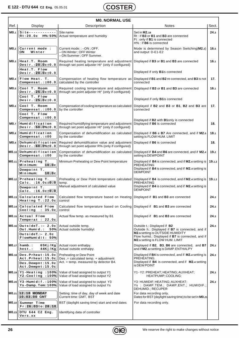
26
E 122 - DTU 644 C2 Eng. 05.05.01
We reserve the right to make changes without notice
COSTER
M0. NORMAL USERef. Display Descriprtion Notes Sect.
S i t e - - - - - - - - - - - -R t : 2 0 . 0 c H%: 5 0%
M0.1 Site nameActual temperature and humidity
24.3Set in M2.18Rt : if B3 or B1 and B3 are connectedFt : only if B1 is connectedH% : if B6 is connected
Cu r r en t mod e :ON Wi n t e r
M0.2 Current mode: : –ON ; OFF.– ON Winter ; OFF Winter– ON Summer ; OFF Summer.
16.5Mode is determined by Season Switching(M2.2)and output D-E1-E2
He a t . T . RoomDe s i r . : 2 0 . 0 c ±0 . 0
M0.3 Required heating temperature and adjustmentthrough set point adjuster Ht° (only if configured)
16.1Displayed if B3 or B1 and B3 are connected
Displayed if only B1 is connectedHe a t . T . F l owDe s i r . : 2 0 . 0 c ±0 . 0
F l ow He a t . T .Compens a t . : ±0 0 . 0
M0.4 Compensation of heating flow temperature ascalculated by the controller
17.Displayed if B1 and B2 re connected, and B3 is notconnected
Coo l T . RoomDe s i r . : 2 5 . 0 c ±0 . 0
M0.5 Required cooling temperature and adjustmentthrough set point adjuster Ht° (only if configured)
16.1
Coo l T . F l owDe s i r . : 2 5 . 0 c ±0 . 0
Displayed if B3 or B1 and B3 are connected
Displayed if only B1 is connected
Coo l T . RoomCompens a t . : ±0 0 . 0
M0.6 Compensation of cooling temperature as calculatedby the controller
17.Displayed if B2 and B3 or B1 , B2 and B3 areconnected
Displayed if B2 with B1only is connected
Coo l T . F l owCompens a t . : ±0 0 . 0
Humi d i f i c a t i onDe s i r . : 5 0 . 0% ±0 . 0
M0.7 Required humidifying temperature and adjustmentthrough set point adjuster Ht° (only if configured)
18.Displayed if B6 is connected
Dehumi d i f i c a t i onDe s i r . : 6 0 . 0% ±0 . 0
M0.9 Required dehumidification value and adjustmentthrough set point adjuster R% (only if configured)
18.Displayed if B6 is connected
Dehumi d i f i c a t i onCompens a t . : ±0 0
M0.10 Compensation of dehumidification as calculatedby the controller
19.2Displayed if B4 and B6 are connected, and if M2.4setting is DEWPOINT
P r ehe a t i ng T .M i n imum: 1 0 . 0 c
M0.11 Minimum Preheating or Dew Point temperature 19.1.2Displayed if B4 is connected, and if M2.4 setting isPREHEATINGDisplayed if B4 is connected, and if M2.4 setting isDEWPOINT
Dewpo i n t T .M i n imum: 1 0 . 0 c
P r ehe a t i ng T .Ca l c . : 1 6 . 0 c ±0 . 0
M0.12 Preheating or Dew Point temperature calculatedtemp.Manual adjustment of calculated value
19.1.2Displayed if B4 is connected, and if M2.4 setting isPREHEATINGDisplayed if B4 is connected, and if M2.4 setting isDEWPOINT
Dewpo i n t T .Ca l c . : 1 6 . 0 c ±0 . 0
Ca l cu l a t ed F l owHe a t i ng T . : 2 2 . 0 c
M0.13 Calculated flow temperature based on Heatingcontrol
24.3Displayed if B1 and B3 are connected
Ca l cu l a t ed F l owCoo l i ng : 3 5 . 0 c
M0.14 Calculated flow temperature based on Coolingcontrol
24.3Displayed if B1 and B3 are connected
Ac t ua l F l owTempe r a t : 2 2 . 0 c
M0.15 Actual flow temp. as measured by B1 24.3Displayed if B1 and B3 are connected
hamb . : 6 5K j / Kghe s t . : 4 4K j / Kg
M0.17 Actual room enthalpy.Actual outside enthalpy.
24.3Displayed if B2, B3, B6 are connected, and B7and if M2.12 setting is DAMP.ENTHALPY
De s . P r he a t : 1 5 . 0 cAc t . P r he a t : 1 5 . 0 c
M0.18 Preheating or Dew PointDes .= calculated temp. + adjustmentAct. = temp. measured by detector B4.
24.3Displayed if B4 is connected, and if M2.4 setting isPREHEATING.Displayed if B4 is connected, and if M2.4 settingis DEW POINT
De s . Dewpn t : 1 5 . 0 cAc t . Dewpn t : 1 5 . 0 c
Y1 - He a t i ng : 1 0 0%Y2 - Coo l i ng : 1 0 0%
M0.19 Value of load assigned to output Y1Value of load assigned to output Y2
24.3Y1 - Y2 : PREHEAT; HEATING; AUXHEAT;HEATPUMP; COOLING;
Y3 - Humi d i f . : 1 0 0%Ys - Damp . Tem: 1 0 0%
M0.20 Value of load assigned to output Y3Value of load assigned to output Ys
24.3Y3 : HUMIDIF; HEATING; AUXHEAT;Ys : DAMP.TEM.; DAMP.ENT.; HUMIDIF.;DEHUMID.; RECUPER
1 2 . 1 8 MONDAY1 0 . 0 3 . 0 0 GMT
M0.21 Setting: time of day, day of week and dateCurrent time: GMT, BST
For data recording only.Dates for BST (daylight saving time) to be set in M0.21
Summer T imeF r : 2 6 . 0 3 t o : 2 8 . 1 0
M0.22 BST (daylight saving time) start and end dates For data recording only.
DTU 6 4 4 C2 Eng .Ve r s . x x
M0.23 Identifying data of controller
Humi d i f i c a t i onCompens a t . : ±0 0
M0.8 Compensation of dehumidification as calculatedby the controller
18.1Displayed if B6 e B7 Are connected, and if M2.5setting is FLOW HUM. LIMIT
Ou t s i deT . : – 2 . 0 cOu t . Humi d . : 5 0%
M0.16 Actual outside temp.Actual outside humidityt
24.3Outside t.: Displayed if B2Outside h.: Displayed if B7 is connected, and ifM2.5 setting is OUTSIDE HUMIDITYFlow humid.: Displayed if B7 is connected, and ifM2.5 setting is FLOW HUM. LIMIT
Ou t s i deT. :– 2 . 0 cF l owHumi d i t : 5 0%
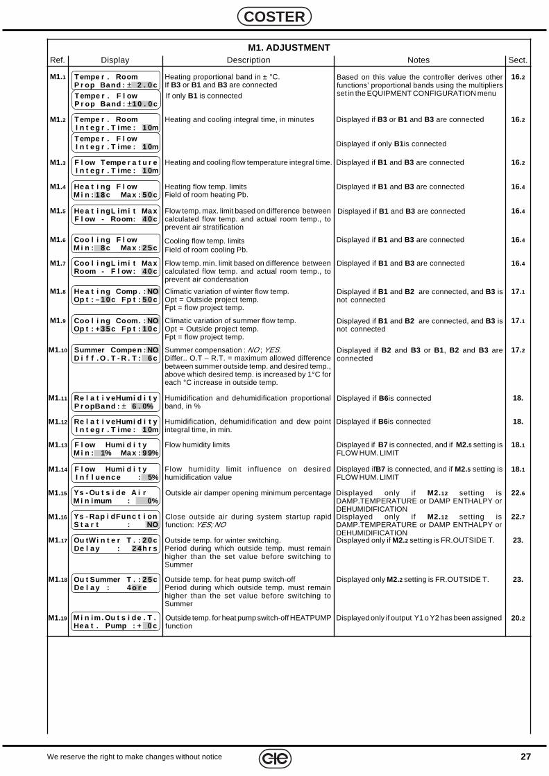
27We reserve the right to make changes without notice
COSTER
M1. ADJUSTMENTRef. Display Description Notes Sect.
Tempe r . RoomP r op Band : ± 2 . 0 c
M1.1 Heating proportional band in ± °C.If B3 or B1 and B3 are connected
16.2Based on this value the controller derives otherfunctions’ proportional bands using the multipliersset in the EQUIPMENT CONFIGURATION menuTempe r . F l ow
P r op Band : ±1 0 . 0 cIf only B1 is connected
Tempe r . RoomI n t eg r . T ime : 1 0m
Heating and cooling integral time, in minutes 16.2Displayed if B3 or B1 and B3 are connected
Displayed if only B1 is connected
M1.2
Tempe r . F l owI n t eg r . T ime : 1 0m
F l ow Tempe r a t u r eI n t eg r . T ime : 1 0m
Heating and cooling flow temperature integral time. 16.2Displayed if B1 and B3 are connectedM1.3
He a t i ng F l owM i n : 1 8 c Ma x : 5 0 c
M1.4 Heating flow temp. limitsField of room heating Pb.
16.4Displayed if B1 and B3 are connected
He a t i ngL imi t Ma xF l ow - Room: 4 0 c
M1.5 Flow temp. max. limit based on difference betweencalculated flow temp. and actual room temp., toprevent air stratification
16.4Displayed if B1 and B3 are connected
Coo l i ng F l owM i n : 8 c Ma x : 2 5 c
M1.6 Cooling flow temp. limitsField of room cooling Pb.
16.4Displayed if B1 and B3 are connected
Coo l i ngL imi t Ma xRoom - F l ow : 4 0 c
M1.7 Flow temp. min. limit based on difference betweencalculated flow temp. and actual room temp., toprevent air condensation
16.4Displayed if B1 and B3 are connected
He a t i ng Comp . : NOOp t : – 1 0 c Fp t : 5 0 c
M1.8 Climatic variation of winter flow temp.Opt = Outside project temp.Fpt = flow project temp.
17.1Displayed if B1 and B2 are connected, and B3 isnot connected
Coo l i ng Coom. : NOOp t : +3 5 c Fp t : 1 0 c
M1.9 Climatic variation of summer flow temp.Opt = Outside project temp.Fpt = flow project temp.
17.1Displayed if B1 and B2 are connected, and B3 isnot connected
Summer Compen : NOD i f f . O . T - R . T : 6 c
M1.10 Summer compensation : NO ; YES.Differ.. O.T – R.T. = maximum allowed differencebetween summer outside temp. and desired temp.,above which desired temp. is increased by 1°C foreach °C increase in outside temp.
17.2Displayed if B2 and B3 or B1 , B2 and B3 areconnected
Re l a t i v eHumi d i t yP r opBand : ± 6 . 0%
M1.11 Humidification and dehumidification proportionalband, in %
18.Displayed if B6 is connected
Re l a t i v eHumi d i t yI n t eg r . T ime : 1 0m
Humidification, dehumidification and dew pointintegral time, in min.
18.Displayed if B6 is connectedM1.12
Outside air damper opening minimum percentageYs - Ou t s i de A i rM i n imum : 0%
M1.15 Displayed only if M2.12 setting isDAMP.TEMPERATURE or DAMP ENTHALPY orDEHUMIDIFICATION
22.6
Close outside air during system startup rapidfunction: YES; NO
Ys - Rap i dFunc t i onS t a r t : NO
M1.16 Displayed only if M2.12 setting isDAMP.TEMPERATURE or DAMP ENTHALPY orDEHUMIDIFICATION
22.7
Ou tWi n t e r T . : 2 0 cDe l a y : 2 4h r s
M1.17 Outside temp. for winter switching.Period during which outside temp. must remainhigher than the set value before switching toSummer
23.Displayed only if M2.2 setting is FR.OUTSIDE T.
Ou t Summer T . : 2 5 cDe l a y : 4o r e
M1.18 Outside temp. for heat pump switch-offPeriod during which outside temp. must remainhigher than the set value before switching toSummer
23.Displayed only M2.2 setting is FR.OUTSIDE T.
Outside temp. for heat pump switch-off HEATPUMPfunction
M i n im. Ou t s i de . T .He a t . Pump : + 0 c
M1.19 Displayed only if output Y1 o Y2 has been assigned 20.2
F l ow Humi d i t yM i n : 1% Ma x : 9 9%
M1.13 Flow humidity limits 18.1Displayed if B7 is connected, and if M2.5 setting isFLOW HUM. LIMIT
F l ow Humi d i t yI n f l uenc e : 5%
M1.14 Flow humidity limit influence on desiredhumidification value
18.1Displayed ifB7 is connected, and if M2.5 setting isFLOW HUM. LIMIT
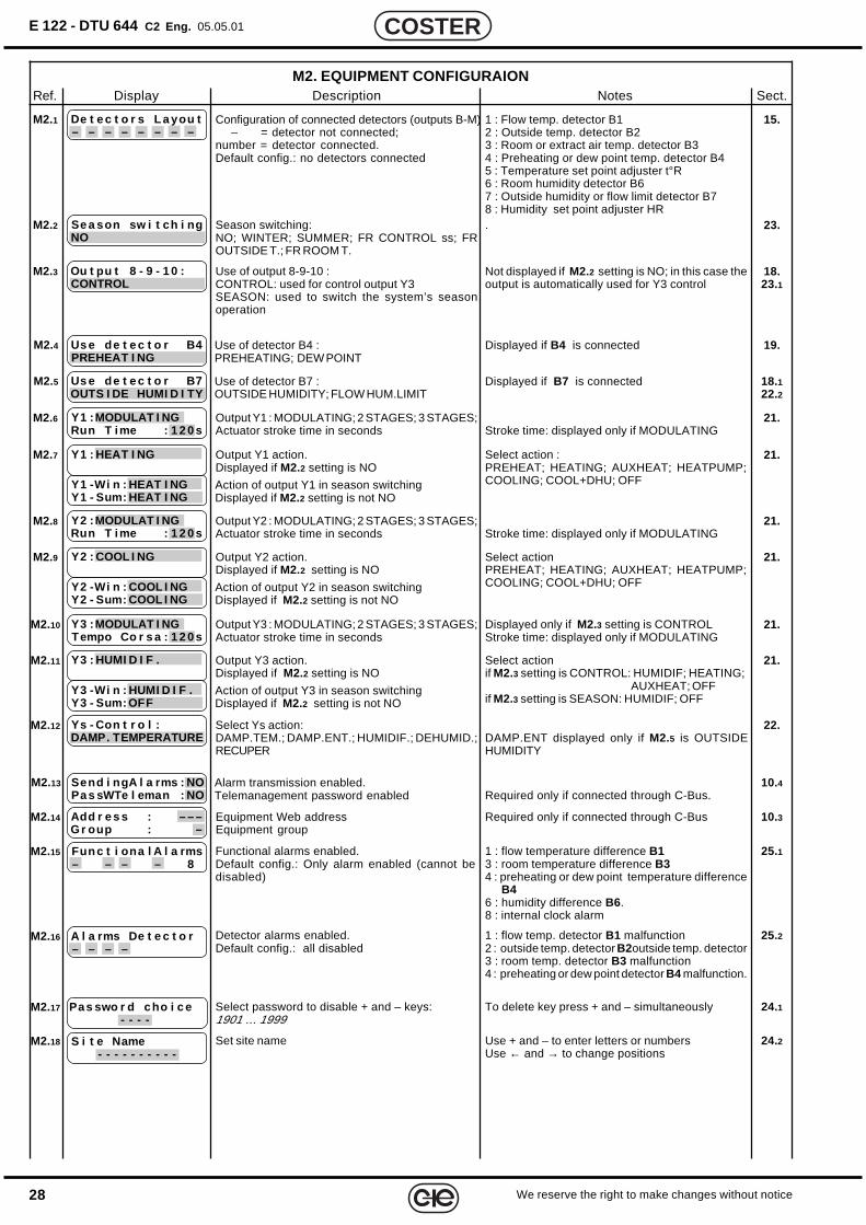
28
E 122 - DTU 644 C2 Eng. 05.05.01
We reserve the right to make changes without notice
COSTER
M2. EQUIPMENT CONFIGURAIONRef. Display Description Notes Sect.
Configuration of connected detectors (outputs B-M)– = detector not connected;
number = detector connected.Default config.: no detectors connected
De t e c t o r s L a you t– – – – – – – –
M2.1 1 : Flow temp. detector B12 : Outside temp. detector B23 : Room or extract air temp. detector B34 : Preheating or dew point temp. detector B45 : Temperature set point adjuster t°R6 : Room humidity detector B67 : Outside humidity or flow limit detector B78 : Humidity set point adjuster HR
15.
Season switching:NO; WINTER; SUMMER; FR CONTROL ss; FROUTSIDE T.; FR ROOM T.
M2.2 . 23.Se a son sw i t ch i ngNO
Use of output 8-9-10 :CONTROL: used for control output Y3SEASON: used to switch the system’s seasonoperation
M2.3 18.23.1
Ou t pu t 8 - 9 - 1 0 :CONTROL
Not displayed if M2.2 setting is NO; in this case theoutput is automatically used for Y3 control
Us e de t e c t o r B4PREHEAT I NG
M2.4 Use of detector B4 :PREHEATING; DEW POINT
19.Displayed if B4 is connected
Output Y1 : MODULATING; 2 STAGES; 3 STAGES;Actuator stroke time in seconds
M2.6Stroke time: displayed only if MODULATING
21.Y1 :MODULAT I NGRun T ime : 1 2 0 s
Output Y1 action.Displayed if M2.2 setting is NO
Y1 : HEAT I NGM2.7 Select action :PREHEAT; HEATING; AUXHEAT; HEATPUMP;COOLING; COOL+DHU; OFF
21.
Y1 -Wi n : HEAT I NGY1 - Sum: HEAT I NG
Action of output Y1 in season switchingDisplayed if M2.2 setting is not NO
Output Y2 : MODULATING; 2 STAGES; 3 STAGES;Actuator stroke time in seconds
M2.8Stroke time: displayed only if MODULATING
21.Y2 :MODULAT I NGRun T ime : 1 2 0 s
Output Y2 action.Displayed if M2.2 setting is NO
Y2 : COOL I NGM2.9 Select actionPREHEAT; HEATING; AUXHEAT; HEATPUMP;COOLING; COOL+DHU; OFF
21.
Y2 -Wi n : COOL I NGY2 - Sum: COOL I NG
Action of output Y2 in season switchingDisplayed if M2.2 setting is not NO
Output Y3 : MODULATING; 2 STAGES; 3 STAGES;Actuator stroke time in seconds
M2.10 Displayed only if M2.3 setting is CONTROLStroke time: displayed only if MODULATING
21.Y3 :MODULAT I NGTempo Co r s a : 1 2 0 s
Output Y3 action.Displayed if M2.2 setting is NO
Y3 : HUMI D I F .M2.11 Select actionif M2.3 setting is CONTROL: HUMIDIF; HEATING;
AUXHEAT; OFFif M2.3 setting is SEASON: HUMIDIF; OFF
21.
Y3 -Wi n : HUMI D I F .Y3 - Sum: OFF
Action of output Y3 in season switchingDisplayed if M2.2 setting is not NO
Select Ys action:DAMP.TEM.; DAMP.ENT.; HUMIDIF.; DEHUMID.;RECUPER
Ys - Con t r o l :DAMP. TEMPERATURE
M2.12DAMP.ENT displayed only if M2.5 is OUTSIDEHUMIDITY
22.
Send i ngA l a rms : NOPa s sWTe l eman : NO
M2.13 Alarm transmission enabled.Telemanagement password enabled
10.4Required only if connected through C-Bus.
10.3Add r e s s : – – –Gr oup : –
M2.14 Equipment Web addressEquipment group
Required only if connected through C-Bus
M2.15 25.1Functional alarms enabled.Default config.: Only alarm enabled (cannot bedisabled)
1 : flow temperature difference B13 : room temperature difference B34 : preheating or dew point temperature difference
B46 : humidity difference B6.8 : internal clock alarm
Fun c t i ona l A l a rms– – – – 8
M2.16 A l a rms De t e c t o r– – – –
25.2Detector alarms enabled.Default config.: all disabled
1 : flow temp. detector B1 malfunction2 : outside temp. detector B2outside temp. detector3 : room temp. detector B3 malfunction4 : preheating or dew point detector B4 malfunction.
M2.17 Pas swo r d cho i c e- - - -
24.1Select password to disable + and – keys:1901 … 1999
To delete key press + and – simultaneously
M2.18 S i t e Name- - - - - - - - - -
24.2Set site name Use + and – to enter letters or numbersUse ← and → to change positions
Us e de t e c t o r B7OUTS I DE HUMI D I TY
M2.5 Use of detector B7 :OUTSIDE HUMIDITY; FLOW HUM.LIMIT
18.122.2
Displayed if B7 is connected
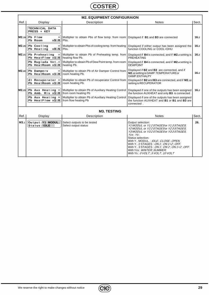
29We reserve the right to make changes without notice
COSTER
M2. EQUIPMENT CONFIGURAIONRef. Display Description Notes Sect.
M3. TESTINGRef. Display Description Notes Sect.
Pb P r ehe a t i ng =Pb He a t F l ow x 1 . 0
M2.21 Multiplier to obtain Pb of Preheating temp. fromheating flow Pb.
16.2Displayed if B4 is connected, and if M2.4 setting isPREHEATING
Pb Rug i ada Ve t . =Pb He a t Room x 1 . 0
Multiplier to obtain Pb of Dew Point temp. from roomheating Pb.
Displayed if B4 is connected, and if M2.4 setting isDEWPOINT
Pb Aux He a t i ng =Pb Amb. R i s x 1 . 0
M2.23 Multiplier to obtain Pb of Auxiliary Heating Controlfrom room heating Pb
16.2Displayed if one of the outputs has been assignedthe function AUXHEAT and only B3 is connected .
Pb Aux He a t i ng =Pb He a t F l ow x 1 . 0
Multiplier to obtain Pb of Auxiliary Heating Controlfrom flow heating Pb
Displayed if one of the outputs has been assignedthe function AUXHEAT and B1 or B1 and B3 areconnected .
Ou t pu t : Y1 MODUL .S t a t us : I DLE
M3.1 Select outputs to be testedSelect output status
26.Output selection:Y1 MODUL. or Y1 2 STAGES or Y1 3 STAGES;Y2 MODUL. or Y2 2 STAGES or Y2 3 STAGES;Y3 MODUL. or Y3 2 STAGES or Y3 3 STAGES;Ycs ; Ys ;Status selection:With Y.. MODUL. : IDLE ; CLOSE ; OPEN.With Y.. 2 STAGES : ON 1 ; ON 1+2 ; OFF.With Y.. 3 STAGES : ON 1 ; ON 2 ; ON 1+2 ; OFF.With Ycs : WINTER; SUMMER.With Ys : 0 VOLT ; 5 VOLT ; 10 VOLT
TECHN I CAL DATAPRESS + KEY
Pb F l ow =Pb Room x 5 . 0
M2.19 Multiplier to obtain Pbs of flow temp. from roomPbs.
16.2Displayed if B1 and B3 are connected
Pb Coo l i ng =Pb He a t i ng x 0 . 5
M2.20 Multiplier to obtain Pbs of cooling temp. from heatingPbs.
16.2Displayed if either output has been assigned thefunction COOLING or COOL+DHU
Pb Dampe r s =Pb He a t Room x 1 . 0
M2.22 Multiplier to obtain Pb of Air Damper Control fromroom heating Pb. 16.2
Displayed if B2 and B3 are connected, and ifM2.12 setting is DAMP.TEMPERATUREorDAMP.ENTHALPY
d t Re cupe r a t o r =Pb He a t Room x 1 . 0
Multiplier to obtain Pb of recuperator Control fromroom heating Pb.
Displayed if B2 and B3 are connected, and if M2.12setting is RECUPERATOR

30
E 122 - DTU 644 C2 Eng. 05.05.01
We reserve the right to make changes without notice
COSTER

31We reserve the right to make changes without notice
COSTER

32
E 122 - DTU 644 C2 Eng. 05.05.01
We reserve the right to make changes without notice
COSTER
D 3
3186
COSTERCONTROLLITEMPERATURAENERGIA
COSTER UNI EN ISO 9002
CISQ/CSQ cert.n°9115.COEE
Head Office & SalesTel. +39.02.2722121 (TI)Tel. +39.02.45476193 (FW)Fax +39.02.2593645
Reg. Off. Central & SouthernTel. +39.06.5573330Fax +39.06.5566517
Orders and ShippingTel. +39.0364.7732.00/02Fax +39.0364.770016
E-mail: [email protected]
20132 MilanVia San G.B. De La Salle, 4/a
00146 RomeViale G. Marconi, 437
25048 Edolo (BS)Via Gen. Treboldi 190/192
Web: www.coster.info