Embed Size (px)
Citation preview
1
E-Beam Lithography Character and StencilCo-Optimization
Wai-Kei Mak, Member, IEEE, and Chris Chu, Fellow, IEEE
Abstract—Electron-beam maskless lithography is being ac-tively explored by the semiconductor industry for chip productionin the sub-22nm regime. Character projection allows in one e-beam shot the printing of complex pattern rather than merely asingle rectangle or triangle as in variable-shaped beam projection.However, those circuit patterns that do not match any characteron the stencil still have to be written by variable-shaped beamprojection. We investigate a new problem of character and stencilco-optimization with blank space sharing between characters soas to minimize the total number of shots required for printing acircuit. We exploit the fact that the blank spaces on the sides ofa character can be adjusted by moving the pattern to be printedwithin its projection region to facilitate blank space sharing soas to pack more characters into the stencil. Even though theco-optimization problem is shown to be NP-complete, we areable to design an elegant approximation algorithm, CASCO.Experiments confirm that the solutions by CASCO are nearlyoptimal. Compared to the published state of the art, CASCOreduces the shot count by 1.59× while it is also orders ofmagnitude faster.
Index Terms—e-beam lithography, character projection, stencildesign.
I. INTRODUCTION
To extend Moore’s law, different solutions like exten-sions of 193 immersion with multiple patterning, extremeultraviolet (EUV) lithography, directed self-assembly (DSA),nanoimprint, and electron beam (e-beam) lithography [1]–[3]are being explored by the semiconductor industry. E-beamlithography directly shoots e-beams onto a wafer to definenanometer structures of a circuit. E-beam lithography hasseveral advantages. Compared to optical lithography, it hasvery high resolution and has no depth of focus problem. Inaddition, e-beam direct write avoids the ever-rising mask costs.But the key issue with e-beam direct write is the time it takesto write a wafer.
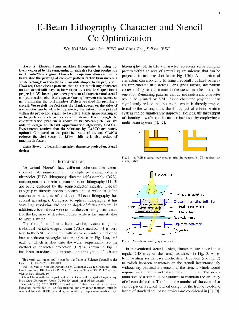
The throughput of an e-beam writing system using thetraditional variable-shaped beam (VSB) method [4] is verylow. In the VSB method, the patterns to be printed are dividedinto constituent rectangles and triangles as in Fig. 1(a), andeach of which is shot onto the wafer sequentially. So themethod of character projection (CP) as shown in Fig. 2has been introduced to improve the throughput of e-beam
This work was supported in part by the National Science Council underGrant NSC 102-2220-E-007-013.
Wai-Kei Mak is with the Department of Computer Science, National TsingHua University, 101 Kuan Fu Rd. Sec. 2, Hsinchu, Taiwan 300 R.O.C. (email:[email protected]).
Chris Chu is with the Department of Electrical and Computer Engineering,Iowa State University, Ames, IA 50010 (email: [email protected]).
Copyright (c) 2013 IEEE. Personal use of this material is permitted.However, permission to use this material for any other purposes must beobtained from the IEEE by sending an email to [email protected].
lithography [5]. In CP, a character represents some complexpattern within an area of several square microns that can beprojected in just one shot (as in Fig. 1(b)). A collection ofcharacters corresponding to some frequently utilized patternsare implemented in a stencil. For a given layout, any patterncorresponding to a character in the stencil can be printed inone shot. Remaining patterns that do not match any characterwould be printed by VSB. Since character projection cansignificantly reduce the shot count, which is directly propor-tional to the writing time, the throughput of e-beam writingsystem can be significantly improved. Besides, the throughputof shooting a wafer can be further increased by employing amulti-beam system [1], [2].
Fig. 1. (a) VSB requires four shots to print the pattern. (b) CP requires justa single shot.
Fig. 2. An e-beam writing system for CP.
In conventional stencil design, characters are placed in aregular 2-D array on the stencil as shown in Fig. 3. An e-beam writing system uses electrostatic deflection (see Fig. 2)to switch between characters on the stencil instantaneouslywithout any physical movement of the stencil, which wouldrequire re-calibration and take orders of minutes. The maxi-mum size of a stencil is constrained to maintain the accuracyof e-beam deflection. This limits the number of characters thatcan be put on a stencil. Stencil design for the front-end-of-linelayers of standard cell-based devices are considered in [6]–[9].
2
Character and/or stencil design for interconnect layers and vialayers are addressed in [8]–[11].
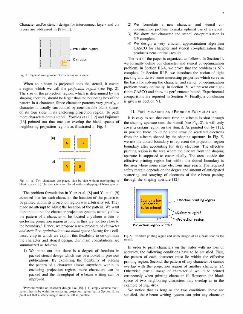
Fig. 3. Typical arrangement of characters on a stencil.
When an e-beam is projected onto the stencil, it coversa region which we call the projection region (see Fig. 2).The size of the projection region, which is determined by theshaping aperture, should be larger than the bounding box of thepattern in a character. Since character patterns vary greatly, acharacter is usually surrounded by considerable blank spaceson its four sides in its enclosing projection region. To packmore characters onto a stencil, Yoshida et al. [12] and Fujimura[13] pointed out that one can overlap the blank spaces ofneighboring projection regions as illustrated in Fig. 4.
Fig. 4. (a) Two characters are placed side by side without overlapping ofblank spaces. (b) The characters are placed with overlapping of blank spaces.
The problem formulation in Yuan et al. [8] and Yu et al. [9]assumed that for each character, the location of the pattern tobe printed within its projection region was arbitrarily set. Theymade no attempt to adjust the location of the pattern. We wantto point out that the character projection systems actually allowthe pattern of a character to be located anywhere within itsenclosing projection region as long as they are not too close tothe boundary.1 Hence, we propose a new problem of characterand stencil co-optimization with blank space sharing for a cell-based chip in which we exploit this flexibility to co-optimizethe character and stencil design. Our main contributions aresummarized as follows.
1) We point out that there is a degree of freedom inpacked stencil design which was overlooked in previouspublications. By exploiting the flexibility of placingthe pattern of a character almost anywhere within itsenclosing projection region, more characters can bepacked and the throughput of e-beam writing can beimproved.
1Previous works on character design like [10], [11] simply assume that apattern has to be within its enclosing projection region, but in Section II, wepoint out that a safety margin must be left in practice.
2) We formulate a new character and stencil co-optimization problem to make optimal use of a stencil.
3) We show that character and stencil co-optimization isNP-complete.
4) We design a very efficient approximation algorithmCASCO for character and stencil co-optimization thatproduces near optimal results.
The rest of the paper is organized as follows. In Section II,we formally define our character and stencil co-optimizationproblem. In Section III-A, we prove that the problem is NP-complete. In Section III-B, we introduce the notion of tightpacking and derive some interesting properties which serve asthe basis for solving the character and stencil co-optimizationproblem nearly optimally. In Section IV, we present our algo-rithm CASCO and show its performance bound. Experimentalcomparisons are reported in Section V. Finally, a conclusionis given in Section VI.
II. PRELIMINARIES AND PROBLEM FORMULATION
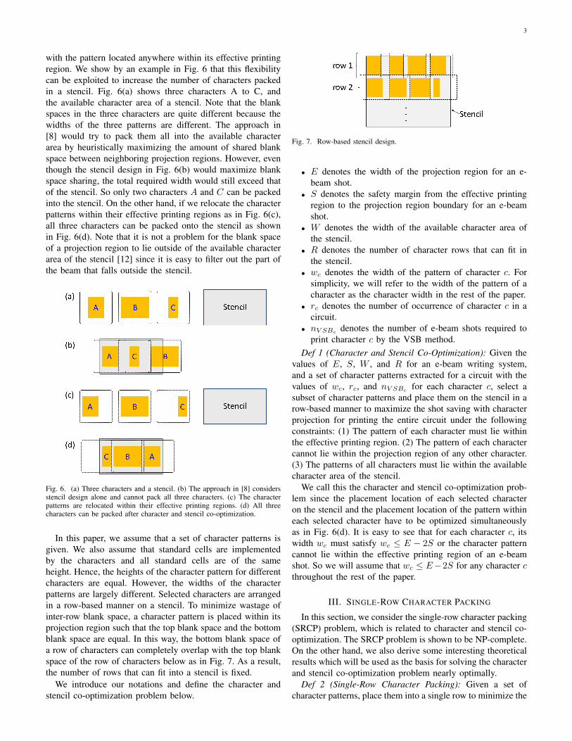
It is easy to see that each time an e-beam is shot throughthe shaping aperture onto the stencil (see Fig. 2), it will onlycover a certain region on the stencil. As pointed out by [12],in practice there could be some stray or scattered electronsfrom the e-beam shaped by the shaping aperture. In Fig. 5,we use the dotted boundary to represent the projection regionboundary after accounting for stray electrons. The effectiveprinting region is the area where the e-beam from the shapingaperture is supposed to cover ideally. The area outside theeffective printing region but within the dotted boundary isthe area where some stray electrons may reach. The requiredsafety margin depends on the degree and amount of anticipatedscattering and straying of electrons of the e-beam passingthrough the shaping aperture [12].
Fig. 5. Effective printing region and safety margin of an e-beam shot on thestencil.
In order to print characters on the wafer with no loss ofaccuracy, the following conditions have to be satisfied. First,the pattern of each character must lie within the effectiveprinting region. Second, the pattern of any character A cannotoverlap with the projection region of another character B.Otherwise, partial image of character A would be printederroneously when printing character B. However, the blankspace of two neighboring characters may overlap as in theexample of Fig. 4(b).
We notice that as long as the two conditions above aresatisfied, the e-beam writing system can print any character
3
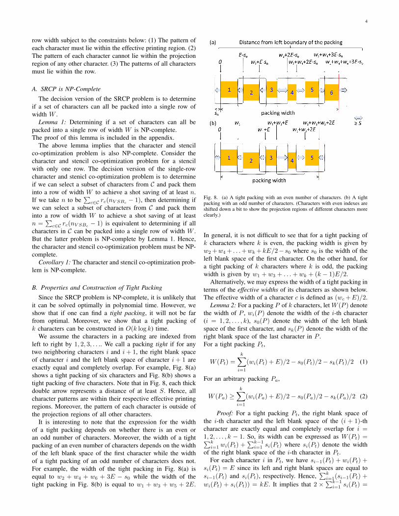
with the pattern located anywhere within its effective printingregion. We show by an example in Fig. 6 that this flexibilitycan be exploited to increase the number of characters packedin a stencil. Fig. 6(a) shows three characters A to C, andthe available character area of a stencil. Note that the blankspaces in the three characters are quite different because thewidths of the three patterns are different. The approach in[8] would try to pack them all into the available characterarea by heuristically maximizing the amount of shared blankspace between neighboring projection regions. However, eventhough the stencil design in Fig. 6(b) would maximize blankspace sharing, the total required width would still exceed thatof the stencil. So only two characters A and C can be packedinto the stencil. On the other hand, if we relocate the characterpatterns within their effective printing regions as in Fig. 6(c),all three characters can be packed onto the stencil as shownin Fig. 6(d). Note that it is not a problem for the blank spaceof a projection region to lie outside of the available characterarea of the stencil [12] since it is easy to filter out the part ofthe beam that falls outside the stencil.
Fig. 6. (a) Three characters and a stencil. (b) The approach in [8] considersstencil design alone and cannot pack all three characters. (c) The characterpatterns are relocated within their effective printing regions. (d) All threecharacters can be packed after character and stencil co-optimization.
In this paper, we assume that a set of character patterns isgiven. We also assume that standard cells are implementedby the characters and all standard cells are of the sameheight. Hence, the heights of the character pattern for differentcharacters are equal. However, the widths of the characterpatterns are largely different. Selected characters are arrangedin a row-based manner on a stencil. To minimize wastage ofinter-row blank space, a character pattern is placed within itsprojection region such that the top blank space and the bottomblank space are equal. In this way, the bottom blank space ofa row of characters can completely overlap with the top blankspace of the row of characters below as in Fig. 7. As a result,the number of rows that can fit into a stencil is fixed.
We introduce our notations and define the character andstencil co-optimization problem below.
Fig. 7. Row-based stencil design.
• E denotes the width of the projection region for an e-beam shot.
• S denotes the safety margin from the effective printingregion to the projection region boundary for an e-beamshot.
• W denotes the width of the available character area ofthe stencil.
• R denotes the number of character rows that can fit inthe stencil.
• wc denotes the width of the pattern of character c. Forsimplicity, we will refer to the width of the pattern of acharacter as the character width in the rest of the paper.
• rc denotes the number of occurrence of character c in acircuit.
• nV SBcdenotes the number of e-beam shots required to
print character c by the VSB method.Def 1 (Character and Stencil Co-Optimization): Given the
values of E, S, W , and R for an e-beam writing system,and a set of character patterns extracted for a circuit with thevalues of wc, rc, and nV SBc for each character c, select asubset of character patterns and place them on the stencil in arow-based manner to maximize the shot saving with characterprojection for printing the entire circuit under the followingconstraints: (1) The pattern of each character must lie withinthe effective printing region. (2) The pattern of each charactercannot lie within the projection region of any other character.(3) The patterns of all characters must lie within the availablecharacter area of the stencil.
We call this the character and stencil co-optimization prob-lem since the placement location of each selected characteron the stencil and the placement location of the pattern withineach selected character have to be optimized simultaneouslyas in Fig. 6(d). It is easy to see that for each character c, itswidth wc must satisfy wc ≤ E − 2S or the character patterncannot lie within the effective printing region of an e-beamshot. So we will assume that wc ≤ E−2S for any character cthroughout the rest of the paper.
III. SINGLE-ROW CHARACTER PACKING
In this section, we consider the single-row character packing(SRCP) problem, which is related to character and stencil co-optimization. The SRCP problem is shown to be NP-complete.On the other hand, we also derive some interesting theoreticalresults which will be used as the basis for solving the characterand stencil co-optimization problem nearly optimally.
Def 2 (Single-Row Character Packing): Given a set ofcharacter patterns, place them into a single row to minimize the
4
row width subject to the constraints below: (1) The pattern ofeach character must lie within the effective printing region. (2)The pattern of each character cannot lie within the projectionregion of any other character. (3) The patterns of all charactersmust lie within the row.
A. SRCP is NP-Complete
The decision version of the SRCP problem is to determineif a set of characters can all be packed into a single row ofwidth W .
Lemma 1: Determining if a set of characters can all bepacked into a single row of width W is NP-complete.The proof of this lemma is included in the appendix.
The above lemma implies that the character and stencilco-optimization problem is also NP-complete. Consider thecharacter and stencil co-optimization problem for a stencilwith only one row. The decision version of the single-rowcharacter and stenicl co-optimization problem is to determineif we can select a subset of characters from C and pack theminto a row of width W to achieve a shot saving of at least n.If we take n to be
∑c∈C rc(nV SBc
− 1), then determining ifwe can select a subset of characters from C and pack theminto a row of width W to achieve a shot saving of at leastn =
∑c∈C rc(nV SBc
− 1) is equivalent to determining if allcharacters in C can be packed into a single row of width W .But the latter problem is NP-complete by Lemma 1. Hence,the character and stencil co-optimization problem must be NP-complete.
Corollary 1: The character and stencil co-optimization prob-lem is NP-complete.
B. Properties and Construction of Tight Packing
Since the SRCP problem is NP-complete, it is unlikely thatit can be solved optimally in polynomial time. However, weshow that if one can find a tight packing, it will not be farfrom optimal. Moreover, we show that a tight packing ofk characters can be constructed in O(k log k) time.
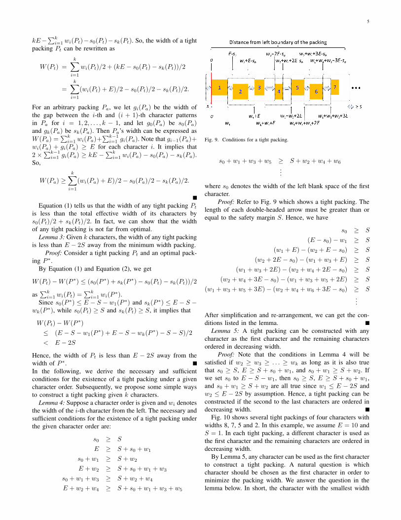
We assume the characters in a packing are indexed fromleft to right by 1, 2, 3, . . .. We call a packing tight if for anytwo neighboring characters i and i+ 1, the right blank spaceof character i and the left blank space of character i + 1 areexactly equal and completely overlap. For example, Fig. 8(a)shows a tight packing of six characters and Fig. 8(b) shows atight packing of five characters. Note that in Fig. 8, each thickdouble arrow represents a distance of at least S. Hence, allcharacter patterns are within their respective effective printingregions. Moreover, the pattern of each character is outside ofthe projection regions of all other characters.
It is interesting to note that the expression for the widthof a tight packing depends on whether there is an even oran odd number of characters. Moreover, the width of a tightpacking of an even number of characters depends on the widthof the left blank space of the first character while the widthof a tight packing of an odd number of characters does not.For example, the width of the tight packing in Fig. 8(a) isequal to w2 + w4 + w6 + 3E − s0 while the width of thetight packing in Fig. 8(b) is equal to w1 + w3 + w5 + 2E.
Fig. 8. (a) A tight packing with an even number of characters. (b) A tightpacking with an odd number of characters. (Characters with even indexes areshifted down a bit to show the projection regions of different characters moreclearly.)
In general, it is not difficult to see that for a tight packing ofk characters where k is even, the packing width is given byw2+w4+ . . .+wk +kE/2− s0 where s0 is the width of theleft blank space of the first character. On the other hand, fora tight packing of k characters where k is odd, the packingwidth is given by w1 + w3 + . . .+ wk + (k − 1)E/2.
Alternatively, we may express the width of a tight packing interms of the effective widths of its characters as shown below.The effective width of a character c is defined as (wc+E)/2.
Lemma 2: For a packing P of k characters, let W (P ) denotethe width of P , wi(P ) denote the width of the i-th character(i = 1, 2, . . . , k), s0(P ) denote the width of the left blankspace of the first character, and sk(P ) denote the width of theright blank space of the last character in P .For a tight packing Pt,
W (Pt) =
k∑i=1
(wi(Pt) + E)/2− s0(Pt)/2− sk(Pt)/2 (1)
For an arbitrary packing Pa,
W (Pa) ≥k∑
i=1
(wi(Pa) + E)/2− s0(Pa)/2− sk(Pa)/2 (2)
Proof: For a tight packing Pt, the right blank space ofthe i-th character and the left blank space of the (i + 1)-thcharacter are exactly equal and completely overlap for i =1, 2, . . . , k − 1. So, its width can be expressed as W (Pt) =∑k
i=1 wi(Pt) +∑k−1
i=1 si(Pt) where si(Pt) denote the widthof the right blank space of the i-th character in Pt.
For each character i in Pt, we have si−1(Pt) + wi(Pt) +si(Pt) = E since its left and right blank spaces are equal tosi−1(Pt) and si(Pt), respectively. Hence,
∑ki=1(si−1(Pt) +
wi(Pt) + si(Pt)) = kE. It implies that 2 ×∑k−1
i=1 si(Pt) =
5
kE−∑k
i=1 wi(Pt)−s0(Pt)−sk(Pt). So, the width of a tightpacking Pt can be rewritten as
W (Pt) =
k∑i=1
wi(Pt)/2 + (kE − s0(Pt)− sk(Pt))/2
=
k∑i=1
(wi(Pt) + E)/2− s0(Pt)/2− sk(Pt)/2.
For an arbitrary packing Pa, we let gi(Pa) be the width ofthe gap between the i-th and (i + 1)-th character patternsin Pa for i = 1, 2, . . . , k − 1, and let g0(Pa) be s0(Pa)and gk(Pa) be sk(Pa). Then Pa’s width can be expressed asW (Pa) =
∑ki=1 wi(Pa)+
∑k−1i=1 gi(Pa). Note that gi−1(Pa)+
wi(Pa) + gi(Pa) ≥ E for each character i. It implies that2 ×
∑k−1i=1 gi(Pa) ≥ kE −
∑ki=1 wi(Pa) − s0(Pa) − sk(Pa).
So,
W (Pa) ≥k∑
i=1
(wi(Pa) + E)/2− s0(Pa)/2− sk(Pa)/2.
Equation (1) tells us that the width of any tight packing Pt
is less than the total effective width of its characters bys0(Pt)/2 + sk(Pt)/2. In fact, we can show that the widthof any tight packing is not far from optimal.
Lemma 3: Given k characters, the width of any tight packingis less than E − 2S away from the minimum width packing.
Proof: Consider a tight packing Pt and an optimal pack-ing P ∗.
By Equation (1) and Equation (2), we get
W (Pt)−W (P ∗) ≤ (s0(P∗) + sk(P
∗)− s0(Pt)− sk(Pt))/2
as∑k
i=1 wi(Pt) =∑k
i=1 wi(P∗).
Since s0(P ∗) ≤ E − S − w1(P∗) and sk(P ∗) ≤ E − S −
wk(P∗), while s0(Pt) ≥ S and sk(Pt) ≥ S, it implies that
W (Pt)−W (P ∗)
≤ (E − S − w1(P∗) + E − S − wk(P
∗)− S − S)/2< E − 2S
Hence, the width of Pt is less than E − 2S away from thewidth of P ∗.In the following, we derive the necessary and sufficientconditions for the existence of a tight packing under a givencharacter order. Subsequently, we propose some simple waysto construct a tight packing given k characters.
Lemma 4: Suppose a character order is given and wi denotesthe width of the i-th character from the left. The necessary andsufficient conditions for the existence of a tight packing underthe given character order are:
s0 ≥ S
E ≥ S + s0 + w1
s0 + w1 ≥ S + w2
E + w2 ≥ S + s0 + w1 + w3
s0 + w1 + w3 ≥ S + w2 + w4
E + w2 + w4 ≥ S + s0 + w1 + w3 + w5
Fig. 9. Conditions for a tight packing.
s0 + w1 + w3 + w5 ≥ S + w2 + w4 + w6
...
where s0 denotes the width of the left blank space of the firstcharacter.
Proof: Refer to Fig. 9 which shows a tight packing. Thelength of each double-headed arrow must be greater than orequal to the safety margin S. Hence, we have
s0 ≥ S
(E − s0)− w1 ≥ S
(w1 + E)− (w2 + E − s0) ≥ S
(w2 + 2E − s0)− (w1 + w3 + E) ≥ S
(w1 + w3 + 2E)− (w2 + w4 + 2E − s0) ≥ S
(w2 + w4 + 3E − s0)− (w1 + w3 + w5 + 2E) ≥ S
(w1 + w3 + w5 + 3E)− (w2 + w4 + w6 + 3E − s0) ≥ S
...
After simplification and re-arrangement, we can get the con-ditions listed in the lemma.
Lemma 5: A tight packing can be constructed with anycharacter as the first character and the remaining charactersordered in decreasing width.
Proof: Note that the conditions in Lemma 4 will besatisfied if w2 ≥ w3 ≥ . . . ≥ wk as long as it is also truethat s0 ≥ S, E ≥ S + s0 + w1, and s0 + w1 ≥ S + w2. Ifwe set s0 to E − S − w1, then s0 ≥ S, E ≥ S + s0 + w1,and s0 + w1 ≥ S + w2 are all true since w1 ≤ E − 2S andw2 ≤ E − 2S by assumption. Hence, a tight packing can beconstructed if the second to the last characters are ordered indecreasing width.
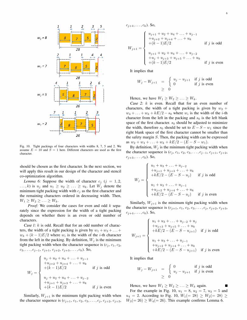
Fig. 10 shows several tight packings of four characters withwidths 8, 7, 5 and 2. In this example, we assume E = 10 andS = 1. In each tight packing, a different character is used asthe first character and the remaining characters are ordered indecreasing width.
By Lemma 5, any character can be used as the first characterto construct a tight packing. A natural question is whichcharacter should be chosen as the first character in order tominimize the packing width. We answer the question in thelemma below. In short, the character with the smallest width
6
Fig. 10. Tight packings of four characters with widths 8, 7, 5 and 2. Weassume E = 10 and S = 1 here. Different characters are used as the firstcharacter.
should be chosen as the first character. In the next section, wewill apply this result in our design of the character and stencilco-optimization algorithm.
Lemma 6: Suppose the width of character cj (j = 1, 2,. . . , k) is uj and u1 ≥ u2 ≥ . . . ≥ uk. Let Wj denote theminimum tight packing width with cj as the first character andthe remaining characters ordered in decreasing width. Then,W1 ≥W2 ≥ . . . ≥Wk.
Proof: We consider the cases for even and odd k sepa-rately since the expression for the width of a tight packingdepends on whether there is an even or odd number ofcharacters.
Case 1: k is odd. Recall that for an odd number of charac-ters, the width of a tight packing is given by w1 +w3 + . . .+wk + (k − 1)E/2 where wi is the width of the i-th characterfrom the left in the packing. By definition, Wj is the minimumtight packing width when the character sequence is (cj , c1, c2,c3, . . . , cj−1, cj+1, cj+2, cj+3, . . . , ck). So,
Wj =
uj + u2 + u4 + . . .+ uj−1+uj+2 + uj+4 + . . .+ uk+(k − 1)E/2 if j is odd
uj + u2 + u4 + . . .+ uj−2+uj+1 + uj+3 + . . .+ uk+(k − 1)E/2 if j is even
Similarly, Wj+1 is the minimum tight packing width whenthe character sequence is (cj+1, c1, c2, c3, . . . , cj , cj+2, cj+3,
cj+4, . . . , ck). So,
Wj+1 =
uj+1 + u2 + u4 + . . .+ uj−1+uj+2 + uj+4 + . . .+ uk+(k − 1)E/2 if j is odd
uj+1 + u2 + u4 + . . .+ uj−2+uj + uj+3 + uj+5 + . . .+ uk+(k − 1)E/2 if j is even
It implies that
Wj −Wj+1 =
{uj − uj+1 if j is odd0 if j is even
≥ 0
Hence, we have W1 ≥W2 ≥ . . . ≥Wk.Case 2: k is even. Recall that for an even number of
characters, the width of a tight packing is given by w2 +w4 + . . .+wk + kE/2− s0 where wi is the width of the i-thcharacter from the left in the packing and s0 is the left blankspace of the first character. s0 should be adjusted to minimizethe width, therefore s0 should be set to E −S −w1 since theright blank space of the first character cannot be smaller thanthe safety margin S. Then, the packing width can be expressedas w2 + w4 + . . .+ wk + kE/2− (E − S − w1).
By definition, Wj is the minimum tight packing width whenthe character sequence is (cj , c1, c2, c3, . . . , cj−1, cj+1, cj+2,cj+3, . . . , ck). So,
Wj =
u1 + u3 + . . .+ uj−2+uj+1 + uj+3 + . . .+ uk+kE/2− (E − S − uj) if j is odd
u1 + u3 + . . .+ uj−1+uj+2 + uj+4 + . . .+ uk+kE/2− (E − S − uj) if j is even
Similarly, Wj+1 is the minimum tight packing width whenthe character sequence is (cj+1, c1, c2, c3, . . . , cj , cj+2, cj+3,cj+4, . . . , ck). So,
Wj+1 =
u1 + u3 + . . .+ uj−2 + uj+uj+3 + uj+5 + . . .+ uk+kE/2− (E − S − uj+1) if j is odd
u1 + u3 + . . .+ uj−1+uj+2 + uj+4 + . . .+ uk+kE/2− (E − S − uj+1) if j is even
It implies that
Wj −Wj+1 =
{0 if j is odduj − uj+1 if j is even
≥ 0
Hence, we have W1 ≥W2 ≥ . . . ≥Wk again.For the example in Fig. 10, u1 = 8, u2 = 7, u3 = 5 and
u4 = 2. According to Fig. 10, W1(= 28) ≥ W2(= 28) ≥W3(= 26) ≥W4(= 26). This example confirms Lemma 6.
7
IV. CASCO: ALGORITHM FOR CHARACTER AND STENCILCO-OPTIMIZATION
Here we present our main algorithm, CASCO, for char-acter and stencil co-optimization. We want to maximize theshot saving with character projection by selecting appropriatecharacters, placing them properly in their effective printingregions, and packing them tightly onto a stencil.
The shot saving of printing a character c by CP instead ofVSB is rc(nV SBC
−1) where rc is the number of occurrence ofcharacter c in the circuit and nV SBc
is the number of e-beamshots required to print c by VSB. We define the efficiency ofa character c as its shot saving per unit effective width, i.e.,2rc(nV SBC
− 1)/(wc +E). Recall that the effective width ofcharacter c is (wc + E)/2.
We will utilize a simple condition for checking whether a setof characters C can be packed within a row without exceedingthe stencil width W in our algorithm. Suppose∑
c∈C(wc + E)/2− (E − wmin(C))/2 ≤W (3)
where min(C) is the minimum width character in C, then allcharacters in C can be packed within a row of the stencil. Theabove is a sufficient condition since Lemma 5 and Equation (1)imply that there exists a tight packing of C with width no morethan
∑c∈C(wc +E)/2− (E − S −wmin(C))/2− S/2 if we
use min(C) as the first character and set the width of its leftblank space to E − S − wmin(C).
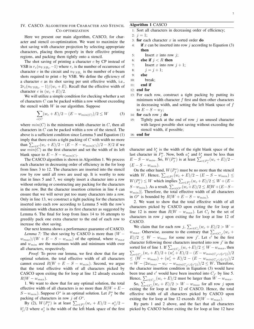
The CASCO algorithm is shown in Algorithm 1. We processeach character in decreasing order of efficiency in the for loopfrom lines 3 to 12. The characters are inserted into the stencilrow by row until all rows are used up. It is worthy to notethat in lines 5 and 7, we simply insert a character into a rowwithout ordering or constructing any packing for the charactersin the row. But the character insertion criterion in line 4 canensure that we will never put too many characters into a row.Only in line 13, we construct a tight packing for the charactersinserted into each row according to Lemma 5 with the row’sminimum width character as its first character as suggested byLemma 6. The final for loop from lines 14 to 16 attempts togreedily pack one extra character to the end of each row toincrease the shot saving.
Our next lemma shows a performance guarantee of CASCO.Lemma 7: The shot saving by CASCO is more than (W −
wmax)/(W + E − S − wmin) of the optimal, where wmax
and wmin are the maximum width and minimum width overall characters, respectively.
Proof: To prove our lemma, we first show that for anyoptimal solution, the total effective width of all characterscannot exceed R(W + E − S − wmin). Second, we arguethat the total effective width of all characters picked byCASCO upon exiting the for loop at line 12 already exceedsR(W − wmax).
1. We want to show that for any optimal solution, the totaleffective width of all characters is no more than R(W +E −S−wmin). Suppose O∗ is an optimal solution. Let P ∗j be thepacking of characters in row j of O∗.
By (2), W (P ∗j ) is at least∑
c∈P∗j(wc + E)/2 − a∗j/2 −
b∗j/2 where a∗j is the width of the left blank space of the first
Algorithm 1 CASCO1: Sort all characters in decreasing order of efficiency;2: j = 1;3: for each character x in sorted order do4: if x can be inserted into row j according to Equation (3)
then5: Insert x into row j;6: else if j < R then7: Insert x into row j + 1;8: j = j + 1;9: else
10: break;11: end if12: end for13: For each row, construct a tight packing by putting its
minimum width character f first and then other charactersin decreasing width, and setting the left blank space of fto E − S − wf ;
14: for each row j do15: Tightly pack at the end of row j an unused character
with largest possible shot saving without exceeding thestencil width, if possible;
16: end for
character and b∗j is the width of the right blank space of thelast character in P ∗j . Now, both a∗j and b∗j must be less thanE − S − wmin. So, W (P ∗j ) is at least
∑c∈P∗
j(wc + E)/2−
(E − S − wmin).On the other hand, W (P ∗j ) must be no more than the stencil
width W . Hence,∑
c∈P∗j(wc + E)/2 − (E − S − wmin) ≤
W (P ∗j ) ≤W which implies∑
c∈P∗j(wc+E)/2 ≤W +(E−
S−wmin). As a result,∑
c∈O∗(wc+E)/2 ≤ R[W+(E−S−wmin)]. Therefore, the total effective width of all charactersin O∗ is bounded by R(W + E − S − wmin).
2. We want to show that the total effective width of allcharacters picked by CASCO upon exiting the for loop atline 12 is more than R(W − wmax). Let Cj be the set ofcharacters in row j upon exiting the for loop at line 12 ofCASCO.
We claim that for each row j,∑
c∈Cj(wc + E)/2 > W −
wmax. Otherwise, assume to the contrary that∑
c∈Cj′(wc +
E)/2 ≤ W − wmax for some row j′. Let c′ be the firstcharacter following those characters inserted into row j′ in thesorted list of line 1. If
∑c∈Cj′
(wc+E)/2 ≤W −wmax, then∑c∈Cj′
(wc +E)/2 + (w′c +E)/2− (E −wmin(Cj′∪{c′}))/2
≤ (W − wmax) + (w′c + E)/2 − (E − wmin(Cj′∪{c′}))/2= W − (2wmax − wc′ − wmin(Cj′∪{c′}))/2 ≤ W . Therefore,the character insertion condition in Equation (3) would havebeen true and c′ would have been inserted into Cj′ by line 5.Hence,
∑c∈Cj′
(wc + E)/2 must be larger than W − wmax.So,
∑c∈Cj
(wc + E)/2 > W − wmax for all row j uponexiting the for loop at line 12 of CASCO. Hence, the totaleffective width of all characters picked by CASCO uponexiting the for loop at line 12 exceeds R(W − wmax).
By parts 1 and 2 above, and the fact that all characterspicked by CASCO before exiting the for loop at line 12 have
8
higher shot saving per unit effective width than any othercharacters, we can conclude that the shot saving by CASCO ismore than (W −wmax)/(W +E−S−wmin) of the optimal.
V. EXPERIMENTAL RESULTS
We have implemented our algorithm CASCO in C andtested it on a Linux server with a 2.67 GHz Intel processor and47 GB of memory. We compare CASCO with the methods in[8] and [9] on stencil design for standard cell-based circuits.We have obtained executable code and benchmarks from theauthors of [8] and [9].
In the first experiment, benchmarks 1D-1 to 1D-4 from[9] were used. Each benchmark contains 1000 character can-didates and the available area of the stencil is 1000µm ×1000µm. Before we can use their benchmarks, we need todefine the effective printing region (or equivalently, the safetymargin) of each benchmark. For each benchmark, we set theeffective printing region to be the smallest value possible (i.e.,the safety margin to be the biggest value possible) such that alloriginal character patterns are still within the effective printingregion.2
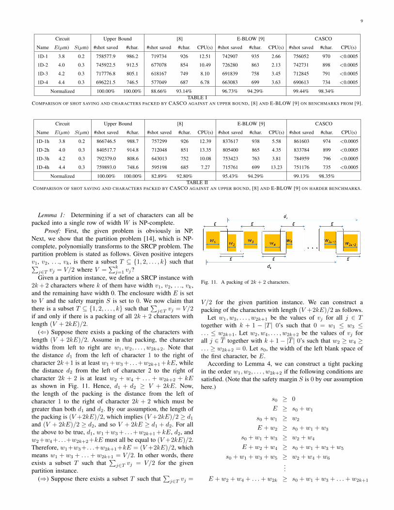
In Table I, we report the values of E and S for eachbenchmark as well as the results of upper bound3, [8], [9],and CASCO. Columns 4, 6, 9, and 12 report the number ofshots that can be saved if CP is also used. Columns 5, 7, 10,and 13 report the number of characters that can be packedin the stencil.4 The runtimes of [8], [9], and CASCO arelisted in columns 8, 11, and 14, respectively. It can be seenthat CASCO achieves near optimal shot saving on all fourbenchmarks. Moreover, as CASCO exploits (1) the flexibilityof placing a character pattern anywhere within its enclosingeffective printing region to increase the amount of blank spacesharing between adjacent characters and (2) the flexibility thatthe blank space of a character can lie outside of the availablecharacter area of the stencil, the number of characters packedin the stencil is about 4% to 5% more than [8] and [9]. It alsoincreases the shot saving by about 11% and 3% comparedto [8] and [9], respectively. Finally, CASCO is orders ofmagnitude faster than the other two methods.
Besides the four benchmarks from [9], we created someharder benchmarks (1D-1h to 1D-4h) for more testing. Werandomly generated 200 extra character candidates with char-acteristics similar to other character candidates into each of theoriginal benchmarks while keeping the stencil size unchanged.The results are shown in Table II. The shot savings by CASCOare again less than 1% away from the upper bound values.Comparing the results in Table II to the results in Table I,we can observe that the solution quality of [8] degraded with
2In other words, S is set to the minimum original blank space on bothsides over all characters.
3Since we have shown in the proof of Lemma 7 that the total effective widthof all characters in an optimal solution cannot exceed R(W+E−S−wmin).An upper bound on shot saving can be obtained by a linear relaxation of a0-1 knapsack problem with capacity R(W +E − S −wmin) such that theprofit and weight of each item correspond to the shot saving and effectivewidth of each character in our problem.
4As the authors of [8] and [9] have given us the updated versions of theircodes, their results here are slightly better than those reported in [9].
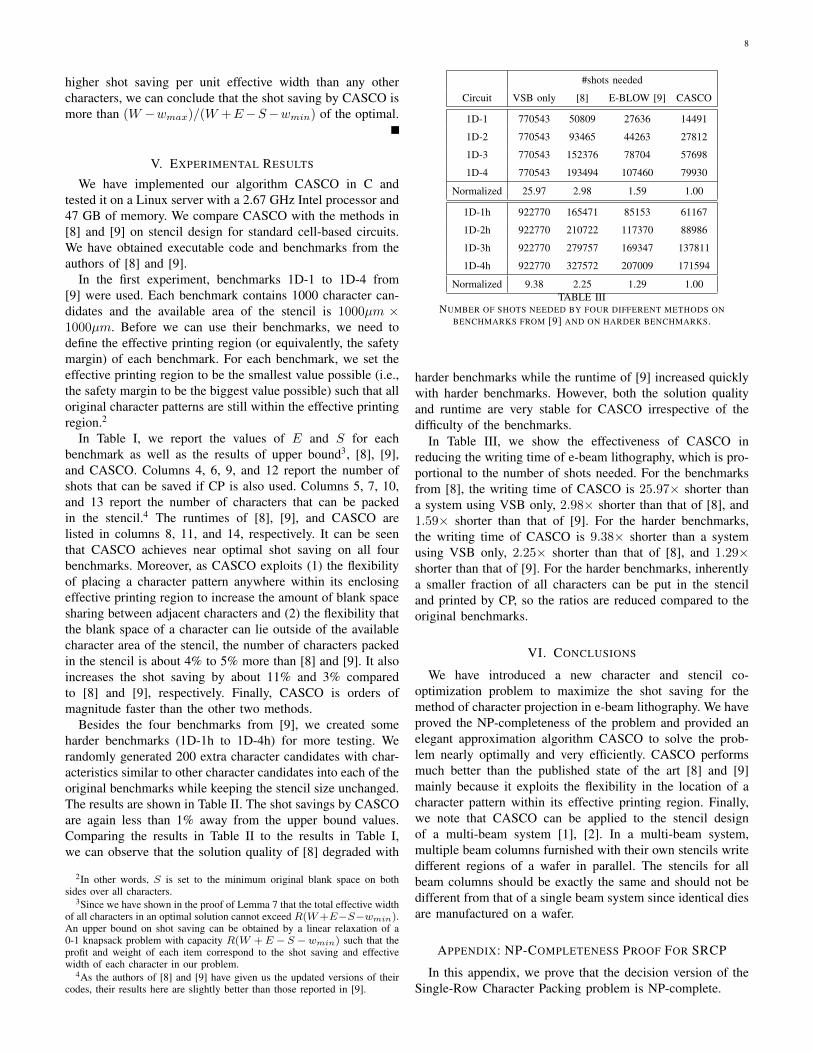
#shots needed
Circuit VSB only [8] E-BLOW [9] CASCO
1D-1 770543 50809 27636 14491
1D-2 770543 93465 44263 27812
1D-3 770543 152376 78704 57698
1D-4 770543 193494 107460 79930
Normalized 25.97 2.98 1.59 1.00
1D-1h 922770 165471 85153 61167
1D-2h 922770 210722 117370 88986
1D-3h 922770 279757 169347 137811
1D-4h 922770 327572 207009 171594
Normalized 9.38 2.25 1.29 1.00TABLE III
NUMBER OF SHOTS NEEDED BY FOUR DIFFERENT METHODS ONBENCHMARKS FROM [9] AND ON HARDER BENCHMARKS.
harder benchmarks while the runtime of [9] increased quicklywith harder benchmarks. However, both the solution qualityand runtime are very stable for CASCO irrespective of thedifficulty of the benchmarks.
In Table III, we show the effectiveness of CASCO inreducing the writing time of e-beam lithography, which is pro-portional to the number of shots needed. For the benchmarksfrom [8], the writing time of CASCO is 25.97× shorter thana system using VSB only, 2.98× shorter than that of [8], and1.59× shorter than that of [9]. For the harder benchmarks,the writing time of CASCO is 9.38× shorter than a systemusing VSB only, 2.25× shorter than that of [8], and 1.29×shorter than that of [9]. For the harder benchmarks, inherentlya smaller fraction of all characters can be put in the stenciland printed by CP, so the ratios are reduced compared to theoriginal benchmarks.
VI. CONCLUSIONS
We have introduced a new character and stencil co-optimization problem to maximize the shot saving for themethod of character projection in e-beam lithography. We haveproved the NP-completeness of the problem and provided anelegant approximation algorithm CASCO to solve the prob-lem nearly optimally and very efficiently. CASCO performsmuch better than the published state of the art [8] and [9]mainly because it exploits the flexibility in the location of acharacter pattern within its effective printing region. Finally,we note that CASCO can be applied to the stencil designof a multi-beam system [1], [2]. In a multi-beam system,multiple beam columns furnished with their own stencils writedifferent regions of a wafer in parallel. The stencils for allbeam columns should be exactly the same and should not bedifferent from that of a single beam system since identical diesare manufactured on a wafer.
APPENDIX: NP-COMPLETENESS PROOF FOR SRCP
In this appendix, we prove that the decision version of theSingle-Row Character Packing problem is NP-complete.
9
Circuit Upper Bound [8] E-BLOW [9] CASCO
Name E(µm) S(µm) #shot saved #char. #shot saved #char. CPU(s) #shot saved #char. CPU(s) #shot saved #char. CPU(s)
1D-1 3.8 0.2 758577.9 986.2 719734 926 12.51 742907 935 2.66 756052 970 <0.0005
1D-2 4.0 0.3 745922.5 912.5 677078 854 10.49 726280 863 2.13 742731 898 <0.0005
1D-3 4.2 0.3 717776.8 805.1 618167 749 8.10 691839 758 3.45 712845 791 <0.0005
1D-4 4.4 0.3 696221.5 746.5 577049 687 6.78 663083 699 3.63 690613 734 <0.0005
Normalized 100.00% 100.00% 88.66% 93.14% 96.73% 94.29% 99.44% 98.34%TABLE I
COMPARISON OF SHOT SAVING AND CHARACTERS PACKED BY CASCO AGAINST AN UPPER BOUND, [8] AND E-BLOW [9] ON BENCHMARKS FROM [9].
Circuit Upper Bound [8] E-BLOW [9] CASCO
Name E(µm) S(µm) #shot saved #char. #shot saved #char. CPU(s) #shot saved #char. CPU(s) #shot saved #char. CPU(s)
1D-1h 3.8 0.2 866746.5 988.7 757299 926 12.39 837617 938 5.58 861603 974 <0.0005
1D-2h 4.0 0.3 840517.7 914.8 712048 851 13.35 805400 865 4.35 833784 899 <0.0005
1D-3h 4.2 0.3 792379.0 808.6 643013 752 10.08 753423 763 3.81 784959 796 <0.0005
1D-4h 4.4 0.3 759893.0 748.6 595198 685 7.27 715761 699 13.23 751176 735 <0.0005
Normalized 100.00% 100.00% 82.89% 92.80% 95.43% 94.29% 99.13% 98.35%TABLE II
COMPARISON OF SHOT SAVING AND CHARACTERS PACKED BY CASCO AGAINST AN UPPER BOUND, [8] AND E-BLOW [9] ON HARDER BENCHMARKS.
Lemma 1: Determining if a set of characters can all bepacked into a single row of width W is NP-complete.
Proof: First, the given problem is obviously in NP.Next, we show that the partition problem [14], which is NP-complete, polynomially transforms to the SRCP problem. Thepartition problem is stated as follows. Given positive integersv1, v2, . . ., vk, is there a subset T ⊆ {1, 2, . . . , k} such that∑
j∈T vj = V/2 where V =∑k
j=1 vj?Given a partition instance, we define a SRCP instance with
2k+2 characters where k of them have width v1, v2, . . ., vk,and the remaining have width 0. The enclosure width E is setto V and the safety margin S is set to 0. We now claim thatthere is a subset T ⊆ {1, 2, . . . , k} such that
∑j∈T vj = V/2
if and only if there is a packing of all 2k + 2 characters withlength (V + 2kE)/2.
(⇐) Suppose there exists a packing of the characters withlength (V + 2kE)/2. Assume in that packing, the characterwidths from left to right are w1, w2, . . . , w2k+2. Note thatthe distance d1 from the left of character 1 to the right ofcharacter 2k+1 is at least w1+w3+ . . .+w2k+1+kE, whilethe distance d2 from the left of character 2 to the right ofcharacter 2k + 2 is at least w2 + w4 + . . . + w2k+2 + kEas shown in Fig. 11. Hence, d1 + d2 ≥ V + 2kE. Now,the length of the packing is the distance from the left ofcharacter 1 to the right of character 2k + 2 which must begreater than both d1 and d2. By our assumption, the length ofthe packing is (V +2kE)/2, which implies (V +2kE)/2 ≥ d1and (V + 2kE)/2 ≥ d2, and so V + 2kE ≥ d1 + d2. For allthe above to be true, d1, w1+w3+ . . .+w2k+1+kE, d2, andw2+w4+. . .+w2k+2+kE must all be equal to (V +2kE)/2.Therefore, w1+w3+. . .+w2k+1+kE = (V +2kE)/2, whichmeans w1 + w3 + . . . + w2k+1 = V/2. In other words, thereexists a subset T such that
∑j∈T vj = V/2 for the given
partition instance.(⇒) Suppose there exists a subset T such that
∑j∈T vj =
Fig. 11. A packing of 2k + 2 characters.
V/2 for the given partition instance. We can construct apacking of the characters with length (V +2kE)/2 as follows.
Let w1, w3, . . . , w2k+1 be the values of vj for all j ∈ Ttogether with k + 1 − |T | 0’s such that 0 = w1 ≤ w3 ≤. . . ≤ w2k+1. Let w2, w4, . . . , w2k+2 be the values of vj forall j ∈ T together with k + 1− |T | 0’s such that w2 ≥ w4 ≥. . . ≥ w2k+2 = 0. Let s0, the width of the left blank space ofthe first character, be E.
According to Lemma 4, we can construct a tight packingin the order w1, w2, . . . , w2k+2 if the following conditions aresatisfied. (Note that the safety margin S is 0 by our assumptionhere.)
s0 ≥ 0
E ≥ s0 + w1
s0 + w1 ≥ w2
E + w2 ≥ s0 + w1 + w3
s0 + w1 + w3 ≥ w2 + w4
E + w2 + w4 ≥ s0 + w1 + w3 + w5
s0 + w1 + w3 + w5 ≥ w2 + w4 + w6
...E + w2 + w4 + . . .+ w2k ≥ s0 + w1 + w3 + . . .+ w2k+1
10
s0 + w1 + w3 + . . .+ w2k+1 ≥ w2 + w4 + . . .+ w2k+2
Since s0 = E = V =∑k
j=1 vj =∑2k+2
j=1 wj , all theinequalities above with s0 on the left hand side must besatisfied. Moreover, since s0 = E, the rest of the inequalitiescan be re-written as
w2 + w4 + . . .+ w2j ≥ w1 + w3 + . . .+ w2j+1 (4)
for j = 0, 1, . . . , k. Note that w2 +w4 + . . .+w2k+2 = w1 +w3+ . . .+w2k+1 = V/2. And w2k+2 = 0 by our assumption,which implies w2+w4+ . . .+w2k = w1+w3+ . . .+w2k+1.In other words, Equation (4) holds for j = k. In addition,since w2 ≥ w4 ≥ . . . ≥ w2k and w1 ≤ w3 ≤ . . . ≤ w2k+1,by induction we can show that Equation (4) holds for j =k− 1, k− 2, . . . , 1. Finally, Equation (4) also holds for j = 0since w1 = 0 by assumption. Therefore, all the conditionsabove are satisfied and by Lemma 4 we can construct a tightpacking in the order w1, w2, . . . , w2k+2.
Moreover, the width of the tight packing is w2+w4+ . . .+wk+2+(2k+2)E/2−s0 = V/2+(2k+2)E/2−E = V/2+kE= (V + 2kE)/2.
REFERENCES
[1] T. Maruyama, Y. Machida, and S. Sugatani. CP based EBDW throughputenhancement for 22nm high volume manufacturing. In Proc. of SPIE7637, pages 76371S–1–76371S–8, Feb. 2010.
[2] T. Maruyama et al. CP element based design for 14nm node EBDWhigh volume manufacturing. In Proc. of SPIE 8323, pages 832314–1–832314–11, Apr. 2012.
[3] B. J. Lin. Future of multiple-E-beam direct-write systems. In Proc. ofSPIE 8323, pages 832302–1–832302–11, March 2012.
[4] H. Pfeiffer. Variable spot shaping for electron-beam lithography. Journalof Vaccum Sci. and Tech., 15(3):887–890, May 1978.
[5] H. Pfeiffer. Recent advances in electron-beam lithography for the high-volume production of VLSI devices. IEEE Trans. on Electron Devices,26(4):663–674, Apr. 1979.
[6] R. Inanami, S. Magoshi, S. Kousai, M. Kamada, T. Takayanagi, K. Sug-ihara, Katsuya Okumura, and T. Kuroda. Throughput enhancementstrategy of maskless electron beam direct writing for logic device. InProc. of International Electron Devices Meeting, pages 833–836, Dec.2000.
[7] M. Sugihara, T. Takata, K. Nakamura, R. Inanami, H. Hayashi,K. Kishimoto, T. Hasebe, Y. Kawano, Y. Matsunaga, K. Murakami,and K. Okumura. Cell library development methodology for throughputenhancement of electron beam direct-write lithography systems. In Proc.of International Symposium on System-on-Chip, pages 137–140, Nov.2005.
[8] K. Yuan, B. Yu, and D. Z. Pan. E-beam lithography stencil planningand optimization with overlapped characters. IEEE Trans. on Computer-Aided Design of Integrated Circuits and Systems, 31(2):167–179, Feb.2012.
[9] B. Yu, K. Yuan, J.-R. Gao, and D.Z. Pan. E-BLOW: e-beam lithographyoverlapping aware stencil planning for MCC system. In Proc. of DesignAutomation Conference, 2013.
[10] P. Du, W. Zhao, S.-H. Weng, C.-K. Cheng, and R. Graham. Characterdesign and stamp algorithms for character projection electron-beamlithography. In Proc. of Asia and South Pacific Design AutomationConference, pages 725–730, Jan. 2012.
[11] R. Ikeno, T. Maruyama, T. Iizuka, S. Komatsu, M. Ikeda, and K. Asada.High-throughput electron beam direct writing of via layers by characterprojection using character sets based on one-dimensional via arrays witharea-efficient stencil design. In Proc. of Asia and South Pacific DesignAutomation Conference, pages 255–260, Jan. 2013.
[12] K. Yoshida, T. Mitsuhashi, S. Matsushita, L. L. Chau, T. D. T. Nguyen,D. MacMillen, and A. Fujimur. Stencil design and method for improvingcharacter density for cell projection charged particle beam lithography.US Patent, Dec. 31, 2009.
[13] A. Fujimura. Design for E-beam: Design insights for direct-writemaskless lithography. In Proc. of SPIE 7823, pages 137–140, Sep. 2010.
[14] Richard Karp. Reducibility among combinatorial problems. In R. E.Miller and J. W. Thatcher, editors, Complexity of Computer Computa-tions, pages 85–103, 1972.
PLACEPHOTOHERE
Wai-Kei Mak Wai-Kei Mak received the B.S. de-gree from the University of Hong Kong, Hong Kong,in 1993, and the M.S. and Ph.D. degrees from theUniversity of Texas at Austin, U.S., in 1995 and1998, respectively, all in computer science.
Dr. Mak is now a Professor with the Departmentof Computer Science, National Tsing Hua Univer-sity, Taiwan. He was Assistant Professor with theDepartment of Computer Science and Engineering,University of South Florida, U.S., from 1999 to2003. His current research interests include VLSI
physical design automation, and CAD for field-programmable technologies.Dr. Mak’s lab won the first place at the FPT 2008 Logic Block Clustering
Contest, the third place at the IEEE CEDA PATMOS 2011 Timing AnalysisContest, and the second place at the TAU 2013 Variation-Aware TimingAnalysis Contest. He has served on the Program and/or the OrganizingCommittee of Asia South Pacific Design Automation Conference, the Inter-national Conference on Field Programmable Logic and Applications, and theInternational Conference on Field-Programmable Technology (FPT). He wasthe Technical Program Chair of FPT in 2006 and was the General Chair ofthe same conference in 2008. Since 2009, he has been a Steering CommitteeMember of the International Conference on Field-Programmable Technology.
PLACEPHOTOHERE
Chris Chu Chris Chu received the B.S. degree incomputer science from the University of Hong Kong,Hong Kong, in 1993. He received the M.S. degreeand the Ph.D. degree in computer science from theUniversity of Texas at Austin in 1994 and 1999,respectively.
Dr. Chu is a Professor in the Electrical andComputer Engineering Department at Iowa StateUniversity. His area of expertises include CAD ofVLSI physical design, and design and analysis ofalgorithms.
Dr. Chu is currently an associate editor for IEEE TCAD and for ACMTODAES. He has served on the technical program committees of severalmajor conferences including DAC, ICCAD, ISPD, ISCAS, DATE, ASP-DAC,and SLIP.
Dr. Chu received the IEEE TCAD best paper award at 1999 for his workin performance-driven interconnect optimization. He received another IEEETCAD best paper award at 2010 for his work in routing tree construction.He received the ISPD best paper award at 2004 for his work in efficientplacement algorithm. He received another ISPD best paper award at 2012 forhis work in floorplan block shaping algorithm. He received the Bert Kay BestDissertation Award for 1998-1999 from the Department of Computer Sciencesin the University of Texas at Austin. He is a Fellow of IEEE.

![A Thesis Engineering By - Nahrain University · 2018. 6. 4. · gravure, planographic or lithography, and stencil or screen printing [34]. SCREEN PRINTING INK: These inks, often known](https://img.pdfslide.net/doc/110x75/6127743edab1422f1644e568/a-thesis-engineering-by-nahrain-university-2018-6-4-gravure-planographic.jpg)