Embed Size (px)
Citation preview
www.engineeringminiprojects.com www.electronicsengineeringprojects.com
1
ABSTRACT
We mean to do by this project, a new system to handle the billing process in
multi branch shops. Present day systems are able to handle this matter, but a large
number of problems ware there. The main target of the project was to allow multi
shop billing even when internet is not available temporarly.
E-Biller is a web based billing system. This system deals with multi branched shops,
e-biller provides a complete solution to all problems that arise in conventional
internet based billing software. Most amazing fact about E-biller is its ability to work
online and offline. Another remarkable feature of the software is that the area
Manager does not need special software but he can do all the controlling activities
with the help of E-biller Website, this permit him to control all the shops under him
from any were in the world.
E-biller is customizable software; this enables it to be used anywhere in the
shopping system. As motioned above E-biller have two Components, Website for the
area manager and the windows form application for the branches. The website could
also act as promoting agent for the sops.
E-biller needs occasional synchronizing with the web server. This process of
synchronizing the local server of each shop with the main web server will enable the
billing control from the web. Internet facility is not always necessary for the
www.engineeringminiprojects.com www.electronicsengineeringprojects.com
www.engineeringminiprojects.com www.electronicsengineeringprojects.com
2
functioning of the software. Local shops could maintain their own independent
server which could be accessed from the web.
E-biller supports barcode facility to make the billing easier. Inter shop
communication is another important feature of the E-biller. Both broadcasting and
individual communication is enabled in this software. Local shops could customize
the software for their special needs.
TABLE OF CONTENTS
Acknowledgement……………………………….
……………………………………... I
Abstract.
………………………………………………………………………………... II
Table of Contents……………………….
……………………………………………...III
List of tables…………………………………………………………………………......V
List of figures…………………………………………………………………………. VI
www.engineeringminiprojects.com www.electronicsengineeringprojects.com
www.engineeringminiprojects.com www.electronicsengineeringprojects.com
3
1. INTRODUCTION 1
1.1 About the project…………………………………………………1
1.2 About the organization…………………………………………...2
1.3 About the platform……………………………………………….2
2. SYSTEM STUDY 5
2.1 Existing packages………………………………………………...5
2.2 Proposed System…………………………………………………..5
2.3 Feasibility and critical factors……………………………………7
3. SYSTEM REQUIREMENTS 8
3.1 Software requirements…………………………………………...8
3.2 Hardware Requirements…………………………………………8
3.3 Selection of Software…………………………………………... 8
4. SYSTEM DESIGN 12
4.1 Elements of design……………………………………………..13
4.1.1 Feasibility factor………………………………...13
www.engineeringminiprojects.com www.electronicsengineeringprojects.com
www.engineeringminiprojects.com www.electronicsengineeringprojects.com
4
4.1.2 Logicalsystem design…………………………….14
4.1.3 Physical system design…………………………...15
4.1.4 Input design……………………………………....15
4.1.4.1 Input design for area manager...................16
4.1.4.2 Input design for shop manager……...…...16
4.1.5 Output design…………………………………….16
4.1.5.1 Output design for area manager…..…..…17
4.1.5.2 Output design for shop manager………...17
4.2 Data flow diagram……………………………………………...17
4.3 Table Design…………………………………………………...23
4.4 User Interface Design…………………………………………..27
5. SYSTEM IMPLEMENTATION 29
5.1 Implementation importance……………………………………. 30
5.2 Data structure……………………………………………………30
5.3 Steps in working………………………………………………...30
6. TESTING METHODOLOGY
33
6.1 Testing objectives…………………………….…………………..33
6.2 Unit testing………………………………….……………………34
www.engineeringminiprojects.com www.electronicsengineeringprojects.com
www.engineeringminiprojects.com www.electronicsengineeringprojects.com
5
6.3 Integration testing……………………………….………………..35
6.4 Validation testing……………………………….………….…….35
7. CONCLUSION 36
7.1 Summary…………………………………………………….….. 36
7.2 Limitations…………………………………………………….…36
7.3 Recommendations and Further Work…………………………....36
8.REFERENCES 37
APPENDIX A–How to use the program……………………….…............................................38
APPENDIX B – Program listing………………………………….…………………………….51
LIST OF TABLES
APPLICATION TABLES
1. Table 4.3.1.1Login Table………………………………………..………….23
2. Table 4.3.1.2Item Table………………………………………….….……....23
3. Table 4.3.1.3Bill Table………………………………………….….……….23
4. Table 4.3.1.4Customer DetailsTable………………………….…..………...24
5. Table 4.3.1.5Shop DetailsTable………………………………….…..……..24
6. Table 4.3.1.6Shop Logo Table…………………………………..………….24
WEBSITE TABLES
www.engineeringminiprojects.com www.electronicsengineeringprojects.com
www.engineeringminiprojects.com www.electronicsengineeringprojects.com
6
7. Table 4.3.2.1 Login Table……………...…………………………..24
8. Table 4.3.2.2 Message Table……………………………………….25
9. Table 4.3.2.3 Registration Table………………………………….. 25
10. Table 4.3.2.4 Local Shop Table…………………………………….25
11. Table 4.3.2.5 Bills In Website…………………………………….. 25
12. Table 4.3.2.6 Customer Details In Web Table……………………..26
www.engineeringminiprojects.com www.electronicsengineeringprojects.com
www.engineeringminiprojects.com www.electronicsengineeringprojects.com
7
LIST OF FIGURES
DFD
1. Figure 4.2.1 Symbols used in DFD……………………………………… …...18
2. Figure 4.2.2 Contest level diagram…………………………………………....19
3. Figure 4.2.3 Level 1:admin side…………………………………….…………19
4. Figure 4.2.4 Level 1.1:Website function…………………………….………...20
5. Figure 4.2.5 Level 2: Local shop………………………………….…...……...21
6. Figure 4.2.6 Level 2.1:Local shop…………………………………………….22
APPLICATION
7. Figure 4.4.1.1 Login Screen…………………………………………………….27
8. Figure 4.4.1.2 Main Billing Form………………………………………………27
9. Figure 4.4.1.3 Database Modifying From………………………………………28
WEBSITE
10. Figure 4.4.2.1 E-biller Home Page……………………………………………..28
11. Figure 4.4.2.2 Administration Page…………………………………………….29
WEBSITE USAGE
12. Figure A.1 E-biller Welcome Page………………………………………….40
13. Figure A.2 Registration Page………………………………………………..40
14. Figure A.3 Administrative Controls Page…………………………………...41
15. Figure A.4 Sending Messages Page…………………………………………41
16. Figure A.5 Bill View Page…………………………………………………..42
17. Figure A.6 Shop Comparing Page …………………………………………..42
18. Figure A.7 Shop Statistics Page……………………………………………..43
www.engineeringminiprojects.com www.electronicsengineeringprojects.com
www.engineeringminiprojects.com www.electronicsengineeringprojects.com
8
INTRODUCTION
1.1 About the project
E-Biller is a web based billing system. This system deals with multi branched shops,
e-biller provides a complete solution to all problems that arise in conventional internet
based billing software. Most amazing fact about E-biller is its ability to work online
and offline. Another remarkable feature of the software is that the area Manager does
not need special software but he can do all the controlling activities with the help of E-
biller Website, this permit him to control all the shops under him from any were in the
world.
E-biller is customizablesoftware; this enables it to be used anywhere in the
shopping system. As motioned above E-biller have two Components, Website for the
area manager and the windows form application for the branches.The website could
also act as promoting agent for the sops.
E-biller needs occasional synchronizing with the web server. This process of
synchronizing the local server of each shop with the main web server will enable the
billing control from the web. Internet facility is not always necessary for the
functioning of the software. Local shops could maintain their own independent server
which could be accessed from the web.
www.engineeringminiprojects.com www.electronicsengineeringprojects.com
www.engineeringminiprojects.com www.electronicsengineeringprojects.com
9
E-biller supports barcode facility to make the billing easier. Inter shop
communication is another important feature of the E-biller. Both broadcasting and
individual communication is enabled in this software. Local shops could customize
the software for their special needs.
1.2 About the organization
1.3 About the platform
To retain the integrity of data generated in different modules, to ensure smooth
flow of control from one module to the other, to provide high quality visual
interface .Net is used as the platform. The .Net initiative offers a complete suit for
developing and deploying applications. This suit consists of .Net products, .Net
services and the .Net framework.
1.3.1 .NET Framework
The foundation behind the design, development and deployment
applications is the .NET framework. Its consistent and simplified programming model
makes it easier to build robust applications.
.NET framework is made of four parts:
• The Common Language Runtime
• A set of Class Libraries
• A set of Programming Languages
• ASP.NET Environment
www.engineeringminiprojects.com www.electronicsengineeringprojects.com
www.engineeringminiprojects.com www.electronicsengineeringprojects.com
10
1.3.2 Advantages of the .NET Framework
• Consistent Programming Model: -
The .NET framework provides a common object-oriented programming model across
languages. This object model can be used in code to perform several tasks.
• Multi- platform applications: -
A .NET application can execute on any architecture that is supported by the
CLR. In future, a CLR version could even be built for non-windows platforms.
• Multi- language integration: -
NET allows multiple languages to be integrated. To enable objects to interact
with each other regardless of the language used to develop them, a set of language
features has been defined in Common Language Specifications (CLS). This
specification includes the basic language features required by many applications.
• Automatic Resource Management: -
While creating an application, a programmer may be required to write codes
for managing resources such as files, memory, network connections and database
resources. If a programmer does not free these resources, the application may not
execute properly. The CLR automatically tracks resources assuage and relieves a
programmer of the task of manual resources management.
• Ease of deployment: -
One of the goals of the .NET framework is to simplify by copying files to the
target computer. Deployment of components has also been simplified. There are
mainly three types- ASP.Net, VB.Net and C#.
www.engineeringminiprojects.com www.electronicsengineeringprojects.com
www.engineeringminiprojects.com www.electronicsengineeringprojects.com
11
ASP.Net is mainly used for web applications. ASP.Net delivers software as Web
services. Therefore, users can subscribe to a web service and use it as long as they
need it, regardless of the hardware and software platform. Microsoft is coming up
with its own set of Web services, known as My Services.
In our project we have used ASP.NET & C#. Front end used in the project is ASP.Net
along with C# and back end is MS SQL 2005. The characteristics of ASP.Net such
consistency in online programming, multi-platform application, multi-language
integration, automatic resource management and ease of deployment helps it in
emerging as an efficient front end. Also for the smooth transition of data from one
module to another, Microsoft SQL finds its way as a successful back end.
www.engineeringminiprojects.com www.electronicsengineeringprojects.com
www.engineeringminiprojects.com www.electronicsengineeringprojects.com
12
2. SYSTEM STUDY
2.1 Existing Package
Current system is the one that work either offline or online. The online system
requires a fulltime internet facility. The offline system won’t support multi shop
managing. The online system needs separate software for head office and local shops.
This made the controlling very tough since one should install software in a system to
view the selling rate or even to send a simple text message to a local shop.
The security features were normal routines. The non-availability of internet facility in
a single shop may lead to complete shutdown of the system due to synchronization
problem. Many of the multi branched shops were running independent software
system for billing, this lead to the overhead problem in calculation of monthly sales.
These systems were not able to compare the sales of two different shops. There are
many drawbacks for the present system.
Drawbacks
Online billing systems won’t support offline billing.
Offline billing systems won’t support Multi shops.
Inter shop communication was not supported.
Low speed of operation due to huge local database.
Manual billing was difficult.
Customizing of software was not possible.
www.engineeringminiprojects.com www.electronicsengineeringprojects.com
www.engineeringminiprojects.com www.electronicsengineeringprojects.com
13
2.2 Proposed System
This system is very advantageous to multi branched shops. Present days the main
problem faced is that if internet connection is not available at a time the billing in
different branches will collapse, or become out of synchronization. Our project is a
solution for this problem it could work online and offline. If the system is offline the
data is temporarily stored in the local machine and whenever internet facility is there
this could be synchronized with the web.
This is a completely automated system which supports customizing even in
database level. This software supports message sending in broadcasting method and
private method. The controlling of the shops could be done from anywhere in the
world. The controlling could be done without any special software; this is enabled
trough the interactive website of e-biller
The proposed system has 2 types of users:
Local Shops
Area manager
2.2.1 Area Manager
Area Manager is considered as the administrator of the E-biller system. The
administrator has full control over the system. He could watch the data of any branch
at any time. He could directly go to the website and log in. he is the one who add or
delete branches to the system. He should accept the registration of a branch to allow
that branch using this system. The administrator could broadcast messages; he could
also send private messages. He could analyse all the shops and their sales.
www.engineeringminiprojects.com www.electronicsengineeringprojects.com
www.engineeringminiprojects.com www.electronicsengineeringprojects.com
14
2.2.2 User (Local Shop Manager)
All local shops are provided with software. When Admin ads a new shop to the list
that shop will get an automatically generated ID number which is used to identify each
shop separately. At the first time running of the software the local shop manager could
use the default password, which he could change after login.
This form application part of the E-biller looks like an ordinary billing software. But it
is fully automated and is customizable. They could check all their messages in just a
single button click. They could modify even the local database. Billing, saving,
viewing, Editing & Customizing are the main options in this part of the system. A
single click Synchronizing system is also provided in the main window.
2.2.3 ADVANTAGES
Manual billing is avoided.
Generate reports and send to web.
No need of fulltime internet facility.
Single click synchronizing facility.
Customizability.
Faster performance.
Comparatively Cheaper.
Barcode enabled billing.
Bill viewing and editing provisions.
Inter shop communication facility.
Modifiable database for adaptability.
Advanced Security features.
Website enables controlling from anywhere in the world.
www.engineeringminiprojects.com www.electronicsengineeringprojects.com
www.engineeringminiprojects.com www.electronicsengineeringprojects.com
15
2.3 FEASIBILITY AND CRITICAL FACTORS
The most creative and challenging phase of the system development life cycle
is the system design. The term design describes the final system and the process by
which it is developed. Sample outputs are also presented. Application design consists
of taking the compiled list of requirements and turning it into detailed specifications.
Data flow diagrams can be used in this phase to clarify the different aspects of
proposed system.
3. SYSTEM REQUIREMENTS
3.1 Software Requirements:
Operating System : Windows XP Professional
Platform : Microsoft .NET
Language : ASP.NET frame work
Web Client : Internet Explorer
Protocol : HTTP
Tools : Microsoft Visual Studio .NET 2008.
3.2 Hardware Requirements:
www.engineeringminiprojects.com www.electronicsengineeringprojects.com
www.engineeringminiprojects.com www.electronicsengineeringprojects.com
16
In order to implement a new system, the choice of the processor with maximum
possible speed is made. There should be sufficient memory to store data and software
tools for efficient processing.
Processor : Intel Pentium IV and above
Hard Disk Space : 40 GB
Display : 15” Colour Monitor
Memory : 512MB
Keyboard : 104 Keys
Components : Optical Mouse, Barcode Reader (optional)
Printer (optional)
3.3 Selection of Software:
The front end used is ASP.NET and C#, back end is MS SQL.
Server side scripting provides dynamic content to users based on the information
stored in a remote location such as a back end database. It includes code written in
server side scripting language, ASP.
3.3.1 ASP.NET
To create dynamic web pages by using server side scripts, Microsoft
has introduced ASP.NET as the .NET version of ASP. ASP.NET is a standard HTML
file that contains embedded server side scripts. ASP.NET provides the following
advantages of server side scripting.
ASP.NET enables you to access information from back-end database and
text files that are stored on a web server or a computer accessible to web server.
www.engineeringminiprojects.com www.electronicsengineeringprojects.com
www.engineeringminiprojects.com www.electronicsengineeringprojects.com
17
ASP.NET auto generate HTML code for each page. Their information
needs to be changed manually when the contents retrieved from data source change.
ASP.NET also enables you to create separate HTML design from the data
retrieval mechanism.
ASP.NET is browser independent.
Features of ASP.NET
Developer Productivity
Easy Programming Model: ASP.NET makes building real world Web
applications dramatically easier.ASP.NET server controls enable an HTML – like
style of declarative. Displaying data, validating user input and uploading files are all
amazingly easy.ASP.NET pages work in all browsers.
Flexible language options: ASP.NET now supports more than 25 .NET
languages (including built in support for VB.NET, C#, and Jscript.NET –no tool
required).
Great tool support: You can now harness the full power of ASP.NET using
any text editor. But Visual Studio.Net adds the productivity of Visual Basic – style
development to the ASP.NET Web Applications.
Rich Class Framework: Application features that used to be hard to
implement, or required a third party component, can now be added in just a few lines
of code using the .NET framework. The .NET framework offers over 4500 classes that
encapsulate rich functionality.
Improved performance and Scalability
www.engineeringminiprojects.com www.electronicsengineeringprojects.com
www.engineeringminiprojects.com www.electronicsengineeringprojects.com
18
Web- Farm Session State: ASP.NET session state lets you share session data
user-specific state values across all machines in your Web farm. Now a user can hit
different servers in the web farm over multiple requests and still have full access to
her session.
Rich Output Caching: ASP.NET output caching could dramatically
improve the performance and scalability of your application. When output caching is
enabled on a page, ASP.NET executes the page just once, and saves the result in
memory in addition to sending to the user. When another user requests the same page,
ASP.NET serves the cached result from memory without re-executing the page.
Enhanced Reliability
“No touch” Application Deployment: ASP.NET dramatically simplifies
installation of your application. With ASP.NET, you can deploy an entire application
as easily as an HTML page.
Dynamic Update of Running Application: ASP.NET now lets you update
compiled components without restarting the web server. With ASP.NET, you simply
copy the component over the existing DLL- ASP.NET will automatically detect the
change and start using the new code.
Easy Migration Path: You don’t have to migrate your existing
applications to start using ASP.NET. ASP.NET runs on IIS side-side with classic ASP
on Windows 2000 and Windows XP platforms. Your existing ASP applications
continue to be processed by ASP.DLL, while the new ASP.NET engine processes new
ASP.NET pages.
3.3.2 C# Programming language
www.engineeringminiprojects.com www.electronicsengineeringprojects.com
www.engineeringminiprojects.com www.electronicsengineeringprojects.com
19
C# is an object-oriented programming language developed by Microsoft as part
of the .NET initiative and later approved as a standard by ECMA (ECMA-334) and
ISO (ISO/IEC 23270). Anders Hejlsberg leads development of the C# language,
which has a procedural, object-oriented syntax based on C++ and includes influences
from aspects of several other programming languages (most notably Delphi and Java)
with a particular emphasis on simplification. By design, C# is the programming
language that most directly reflects the underlying Common Language Infrastructure
(CLI). Most of C#'s intrinsic types correspond to value-types implemented by the CLI
framework. However, the C# language specification does not state the code generation
requirements of the compiler: that is, it does not state that a C# compiler must target a
Common Language Runtime (CLR), or generate Common Intermediate Language
(CIL), or generate any other specific format. Theoretically, a C# compiler could
generate machine code like traditional compilers of C++ or FORTRAN; in practice,
all existing C# implementations target CLI.
3.3.3 Microsoft SQL Server
Microsoft SQL Server is a relational database management system
(RDBMS) produced by Microsoft. Its primary query language is Transact-SQL, an
implementation of the ANSI/ISO standard Structured Query Language (SQL) used by
both Microsoft and Sybase.
Features of MS-SQL Server
Graphical Tool
Microsoft SQL Server 2005 SQL Query Analyzer is a graphical tool
that allows you to:
www.engineeringminiprojects.com www.electronicsengineeringprojects.com
www.engineeringminiprojects.com www.electronicsengineeringprojects.com
20
Create queries and other SQL scripts and execute them against SQL Server
databases (Query window).
Quickly create commonly used database objects from predefined scripts
(Templates).
Quickly copy existing database objects (Object Browser scripting feature).
Execute stored procedures without knowing the parameters (Object
Browser procedure execution feature).
Debug stored procedures (T-SQL Debugger).
Debug query performance problems (Show Execution Plan, Show Server
Trace, Show Client Statistics, Index Tuning Wizard).
Locate objects within databases (object search feature), or view and work
with objects (Object Browser).
Quickly insert, update, or delete rows in a table (Open Table window).
Create keyboard shortcuts for frequently used queries (custom query
shortcuts feature).
Add frequently used commands to the Tools menu (customized Tools
menu feature).
www.engineeringminiprojects.com www.electronicsengineeringprojects.com
www.engineeringminiprojects.com www.electronicsengineeringprojects.com
21
4. SYSTEM DESIGN
The most creative and challenging phase of the system development life
cycle is the system design. The term design describes the final system and the process
by which it is developed. It refers to the technical specifications that will be applied in
implementing the candidate system. The first step is to determine how the output is to
be produced and in what format. Sample outputs are also presented.
Design is the process of creating alternative solutions evaluating the
choice and drawing up the specifications for the chosen alternative. System design
work follows logically from system analysis. Identifying where a system may be
improved leads on how the system can be improved and in particular advantage of
computer use.
Application design consists of taking the compiled list of
requirements and turning into detailed specification describes the new system. Many
of the tools used in the analysis phase can be used in this phase to clarify the different
www.engineeringminiprojects.com www.electronicsengineeringprojects.com

www.engineeringminiprojects.com www.electronicsengineeringprojects.com
22
aspects of the proposed system. Dataflow diagrams can be used in this phase to clarify
the different aspects of the proposed system. The general process that use here for
object-oriented design has a number of stages
Understand and define content and the modes of use of the system.
Design the system architecture.
Identify the system objects in the system.
Develop design models.
Specify object interface.
4.1 Elements of Design
4.1.1 Feasibility Factor:
Feasibility factor are those factors that determine whether the software
developed satisfies the minimum requirement. Feasibility factors are requirements that
describe system behaviour. In any given state, the system satisfies a set of conditions;
when the system acts, it may change its overall state by changing the state of an
object. The requirements describe the activities of the system.
Requirements are of two ways.
1. Functional
2. Non-functional
A functional requirement describes an interaction between the system and its
environment. A non-functional requirement describes a restriction on the system that
limits the choice for constructing a solution to the problem.
The system design consists of
1. Logical design
www.engineeringminiprojects.com www.electronicsengineeringprojects.com
www.engineeringminiprojects.com www.electronicsengineeringprojects.com
23
2. Physical design
4.1.2 Logical System Design:
The data flow oriented design has been adopted for the system. The
main attraction of the data flow-oriented design is that it is amenable to a wide range
of application areas. Data flow diagrams show the logical flow of the system and
define boundaries of the system. It describes the inputs (source), output (destination),
database (data sources) and procedures (data flows), all in a format that meets the
user’s requirements. While preparing the logical system design, it is tried to specify
the user’s need at all level of detail that virtually determines the information flow into
and out of the system. The required data sources and the specific objectives of the
design where also considered. The outline design of the needed reports and input
forms was defined.
Data is the key to the overall system and it is structured to meet the user
requirement. Each item of data is uniquely and defined in the database. The
relationship between various items of data was identified. The data are analysed to
determine whether they are normalized. Then the procedures handled by the computer
and human beings are also determined. The users were informed about the logical
design of the system.
4.1.3 Physical System Design:
Physical design produces working system by defining specification
and the necessary programs are written based on this, which performs necessary
calculations through the existing database produce report and maintains updated
database at all time.
Physical design consists of:
Input design
www.engineeringminiprojects.com www.electronicsengineeringprojects.com
www.engineeringminiprojects.com www.electronicsengineeringprojects.com
24
Output design
Program design
4.1.4 Input Design:
Input design is the process of converting user-originated inputs to a
computer-based format. The goal of designing input data is to make entry as easy and
free from errors as possible.
Well-designed inputs serve five purposes,
Control work flow
Reduced redundancies
Record data
Increase clerical accuracy
Allow easier checking of data
Inputs are important because in many instances, they are the contact a
user has with a system. When the data keyed into the system, the operator must
receive the data in a form that are readily understood. The key operator should key the
data in the order in which it occurs on the form and the computer should reform it
when required.
The projects input design constitutes:
4.1.4.1 Input design for Area Manager
Area Manager is the one who accepts the registered shops and provide the user
id for the local shop. He could uniquely identify the local shops by using this given id.
www.engineeringminiprojects.com www.electronicsengineeringprojects.com
www.engineeringminiprojects.com www.electronicsengineeringprojects.com
25
He is also able to remove shops from the database. Administrator is the one who
enters the messages to local shops.
4.1.4.2 Input design for Local Shop Manager
Local Shop Manager is the one who creates the local database for billing. That is he is
the one who adds the different items to the database. He could also modify the
database.
Local shop manager or the user is the one who enters the data of each bill to the local
database which is synchronized to the main web database later. He could also enter
custom data to modify the user interface of the software
4.1.5 Output Design:
Outputs from the computer system are required primarily to
communicate the results of processing to the users. Output design is an on-going
activity during the study phase. The objective of output design is to define the
contents and format of all documents and reports in an attractive and useful format.
Other reason for output generations are:
To provide proper communication of data to the user.
To re-input to the computer for being connected with other data
and further processing.
To provide permanent storage.
Output generally refers to the results and information that are
generated by the system. It can be in the form of operational documents or a report.
Since some of the end users will not actually operate the information system or input
through workstations. The Project’s output design constitutes:
www.engineeringminiprojects.com www.electronicsengineeringprojects.com
www.engineeringminiprojects.com www.electronicsengineeringprojects.com
26
4.1.5.1 Output design for Area Manager:
Area manager receives the entire billing data of each shop along with their
unique id. He gets the replay to messages that had send to local shops. Admin get the
details of each shop regularly
4.1.5.2 Output design for Local Shop Manager:
Each Shops get a unique ID when register in the net. This unique id is returned
each time when a local shop communicates with the web. The synchronization also
needs the retrieval of unique id of the shop.
4.2 DFD
Data flow diagram is used to define the flow of the system and its
resources such as information. Data flow diagrams are a way of expressing system
requirements in a graphical manner. Data flow diagrams represent one of the most
ingenious tools used for structured analysis. A data flow diagram or DFD as it is
shortly called is also known as a bubble chart. It has the purpose of clarifying system
requirements and identifying major transformations that will become programs in the
system design. It is the major starting point in the design phase that functionally
decomposes the requirement specifications down to the lowest level of detail. To draw
DFD
Look at the system from the inside to the outside.
Identify the activities.
Locate the data flow.
Show the internal inputs that exist within the system.
www.engineeringminiprojects.com www.electronicsengineeringprojects.com
www.engineeringminiprojects.com www.electronicsengineeringprojects.com
27
Look for duplication of data flows or stores (files).
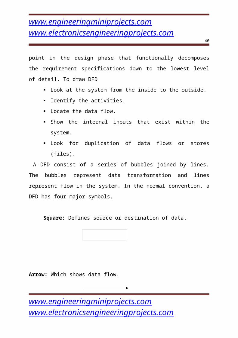
A DFD consist of a series of bubbles joined by lines. The bubbles represent data
transformation and lines represent flow in the system. In the normal convention, a
DFD has four major symbols.
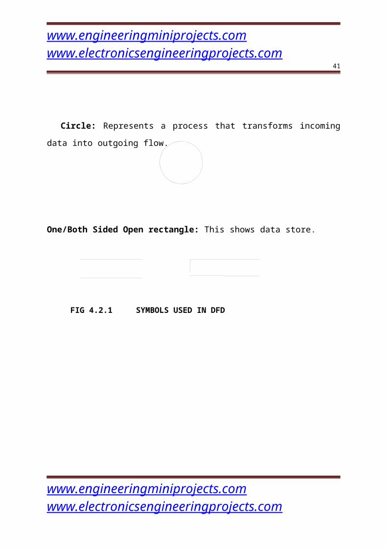
Square: Defines source or destination of data.
Arrow: Which shows data flow.
Circle: Represents a process that transforms incoming data into outgoing flow.
One/Both Sided Open rectangle: This shows data store.
FIG 4.2.1 SYMBOLS USED IN DFD
www.engineeringminiprojects.com www.electronicsengineeringprojects.com
www.engineeringminiprojects.com www.electronicsengineeringprojects.com
28
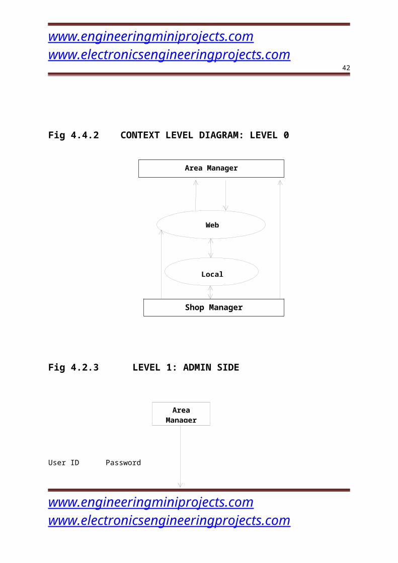
Fig 4.4.2 CONTEXT LEVEL DIAGRAM: LEVEL 0
Fig 4.2.3 LEVEL 1: ADMIN SIDE
www.engineeringminiprojects.com www.electronicsengineeringprojects.com
Area Manager
Shop Manager
Local Component
Web Component
Area Manager
www.engineeringminiprojects.com www.electronicsengineeringprojects.com
29
User ID Password
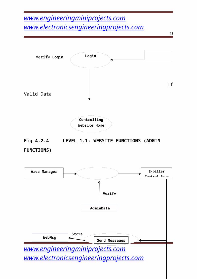
Verify Login
If Valid Data
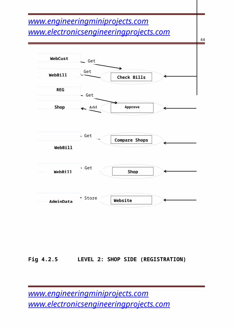
Fig 4.2.4 LEVEL 1.1: WEBSITE FUNCTIONS (ADMIN FUNCTIONS)
WebMsg
REG
www.engineeringminiprojects.com www.electronicsengineeringprojects.com
Login
Controlling Website Home
Area Manager E-biller Control PageLog in
Send Messages
Check Bills
Approve Registration
Get data
WebBill
WebCust
AdminData
Verify
Get data
Get data
Store
www.engineeringminiprojects.com www.electronicsengineeringprojects.com
30
Shop
WebBill
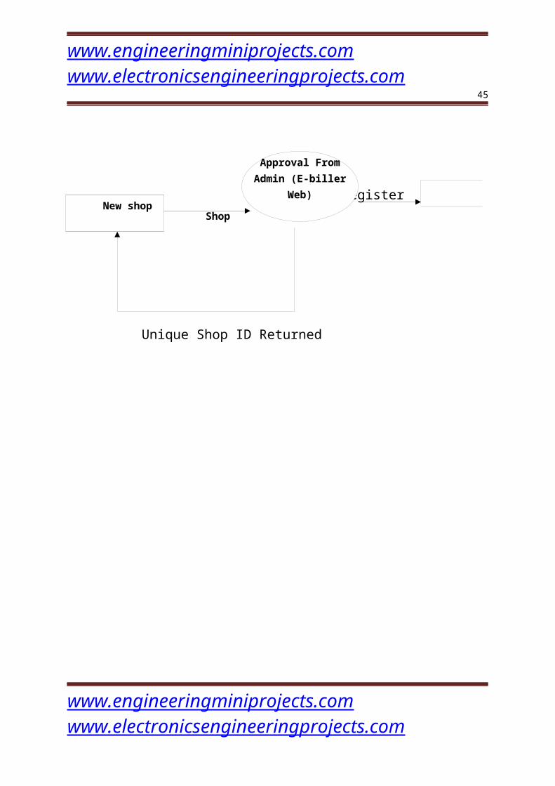
Fig 4.2.5 LEVEL 2: SHOP SIDE (REGISTRATION)
Register Store Shop
Unique Shop ID Returned
www.engineeringminiprojects.com www.electronicsengineeringprojects.com
Add
WebBill
AdminData
Get data
Get data
Store
New shop
Approval From Admin (E-biller Web)

www.engineeringminiprojects.com www.electronicsengineeringprojects.com
31
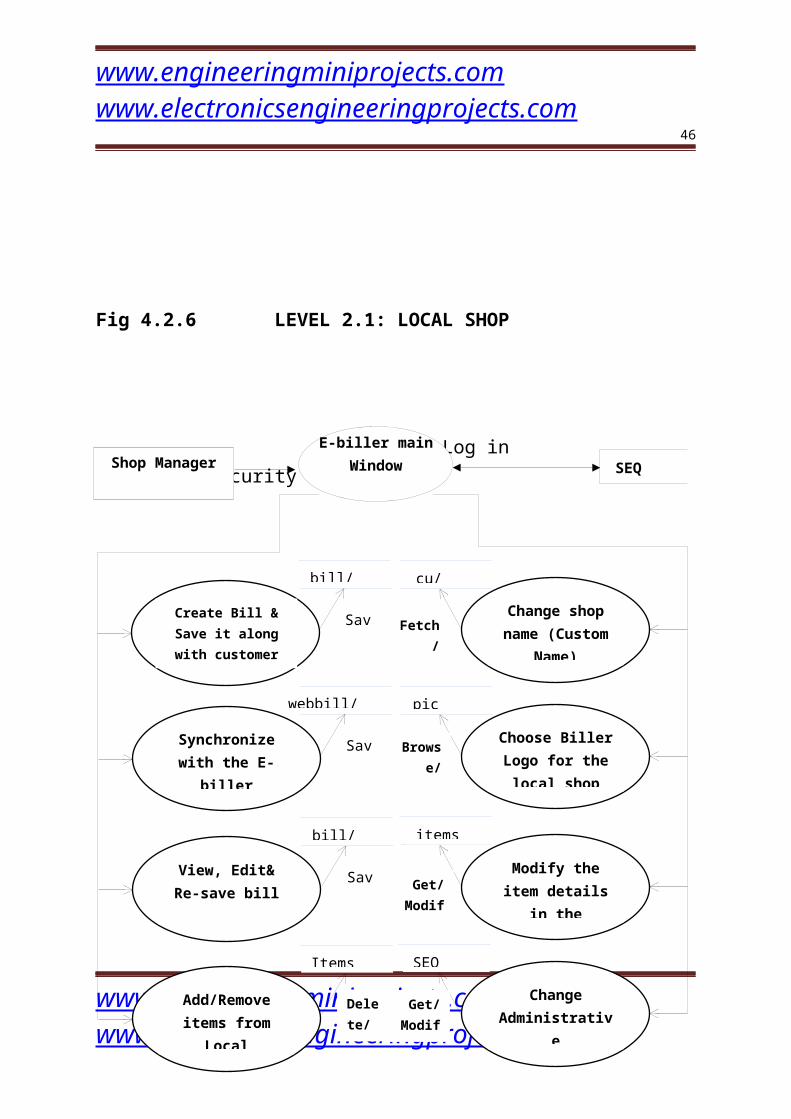
Fig 4.2.6 LEVEL 2.1: LOCAL SHOP
Log in Logindata/security
www.engineeringminiprojects.com www.electronicsengineeringprojects.com
Shop ManagerE-biller main
Window SEQ
Create Bill & Save it along with customer
information
Synchronize with the E-biller
website
Change shop name (Custom Name)
Choose Biller Logo for the local shop
bill/custbill
Save
Save
webbill/webcust
cu/custom
pic
Browse/Save
Fetch/ Save
www.engineeringminiprojects.com www.electronicsengineeringprojects.com
32
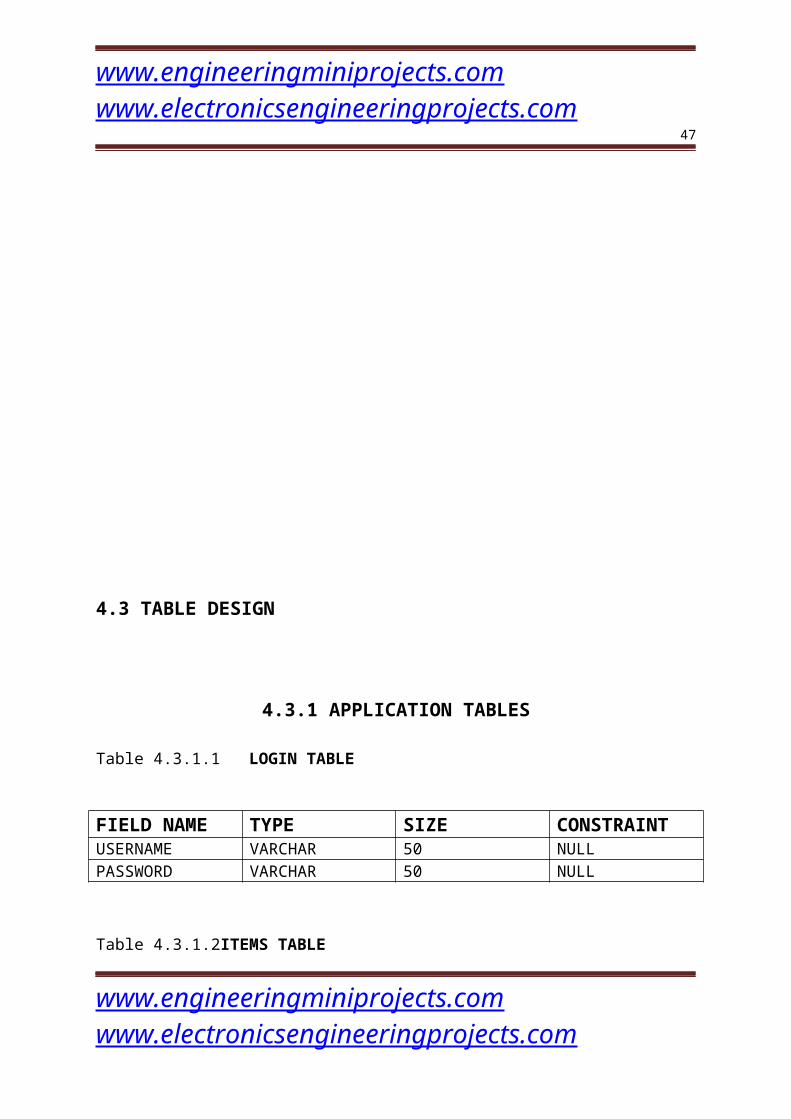
4.3 TABLE DESIGN
4.3.1 APPLICATION TABLES
Table 4.3.1.1 LOGIN TABLE
FIELD NAME TYPE SIZE CONSTRAINT
www.engineeringminiprojects.com www.electronicsengineeringprojects.com
www.engineeringminiprojects.com www.electronicsengineeringprojects.com
33
USERNAME VARCHAR 50 NULLPASSWORD VARCHAR 50 NULL
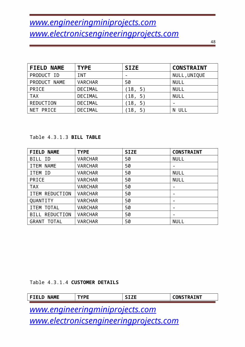
Table 4.3.1.2ITEMS TABLE
FIELD NAME TYPE SIZE CONSTRAINTPRODUCT ID INT - NULL,UNIQUEPRODUCT NAME VARCHAR 50 NULLPRICE DECIMAL (18, 5) NULLTAX DECIMAL (18, 5) NULLREDUCTION DECIMAL (18, 5) -NET PRICE DECIMAL (18, 5) N ULL
Table 4.3.1.3 BILL TABLE
FIELD NAME TYPE SIZE CONSTRAINTBILL ID VARCHAR 50 NULLITEM NAME VARCHAR 50 -ITEM ID VARCHAR 50 NULLPRICE VARCHAR 50 NULLTAX VARCHAR 50 -ITEM REDUCTION VARCHAR 50 -QUANTITY VARCHAR 50 -ITEM TOTAL VARCHAR 50 -BILL REDUCTION VARCHAR 50 -GRANT TOTAL VARCHAR 50 NULL
Table 4.3.1.4 CUSTOMER DETAILS
FIELD NAME TYPE SIZE CONSTRAINTBILL ID VARCHAR 50 NULLCUSTOMER NAME VARCHAR 50 -
www.engineeringminiprojects.com www.electronicsengineeringprojects.com
www.engineeringminiprojects.com www.electronicsengineeringprojects.com
34
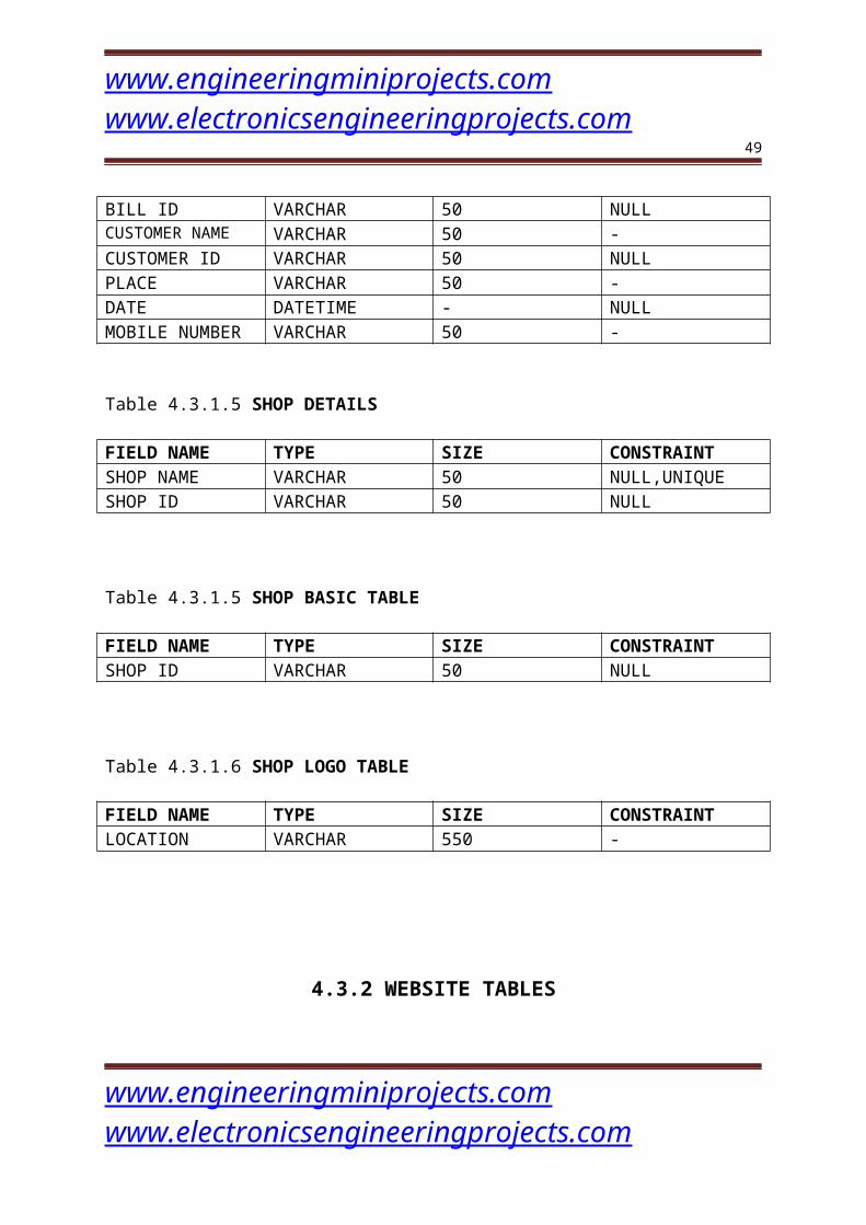
CUSTOMER ID VARCHAR 50 NULLPLACE VARCHAR 50 -DATE DATETIME - NULLMOBILE NUMBER VARCHAR 50 -
Table 4.3.1.5 SHOP DETAILS
FIELD NAME TYPE SIZE CONSTRAINTSHOP NAME VARCHAR 50 NULL,UNIQUESHOP ID VARCHAR 50 NULL
Table 4.3.1.5 SHOP BASIC TABLE
FIELD NAME TYPE SIZE CONSTRAINTSHOP ID VARCHAR 50 NULL
Table 4.3.1.6 SHOP LOGO TABLE
FIELD NAME TYPE SIZE CONSTRAINTLOCATION VARCHAR 550 -
4.3.2 WEBSITE TABLES
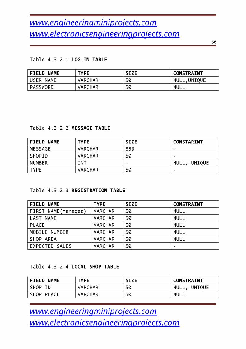
Table 4.3.2.1 LOG IN TABLE
FIELD NAME TYPE SIZE CONSTRAINTUSER NAME VARCHAR 50 NULL,UNIQUEPASSWORD VARCHAR 50 NULL
www.engineeringminiprojects.com www.electronicsengineeringprojects.com
www.engineeringminiprojects.com www.electronicsengineeringprojects.com
35
Table 4.3.2.2 MESSAGE TABLE
FIELD NAME TYPE SIZE CONSTARINTMESSAGE VARCHAR 850 -SHOPID VARCHAR 50 -NUMBER INT - NULL, UNIQUETYPE VARCHAR 50 -
Table 4.3.2.3 REGISTRATION TABLE
FIELD NAME TYPE SIZE CONSTRAINTFIRST NAME(manager) VARCHAR 50 NULLLAST NAME VARCHAR 50 NULLPLACE VARCHAR 50 NULLMOBILE NUMBER VARCHAR 50 NULLSHOP AREA VARCHAR 50 NULLEXPECTED SALES VARCHAR 50 -
Table 4.3.2.4 LOCAL SHOP TABLE
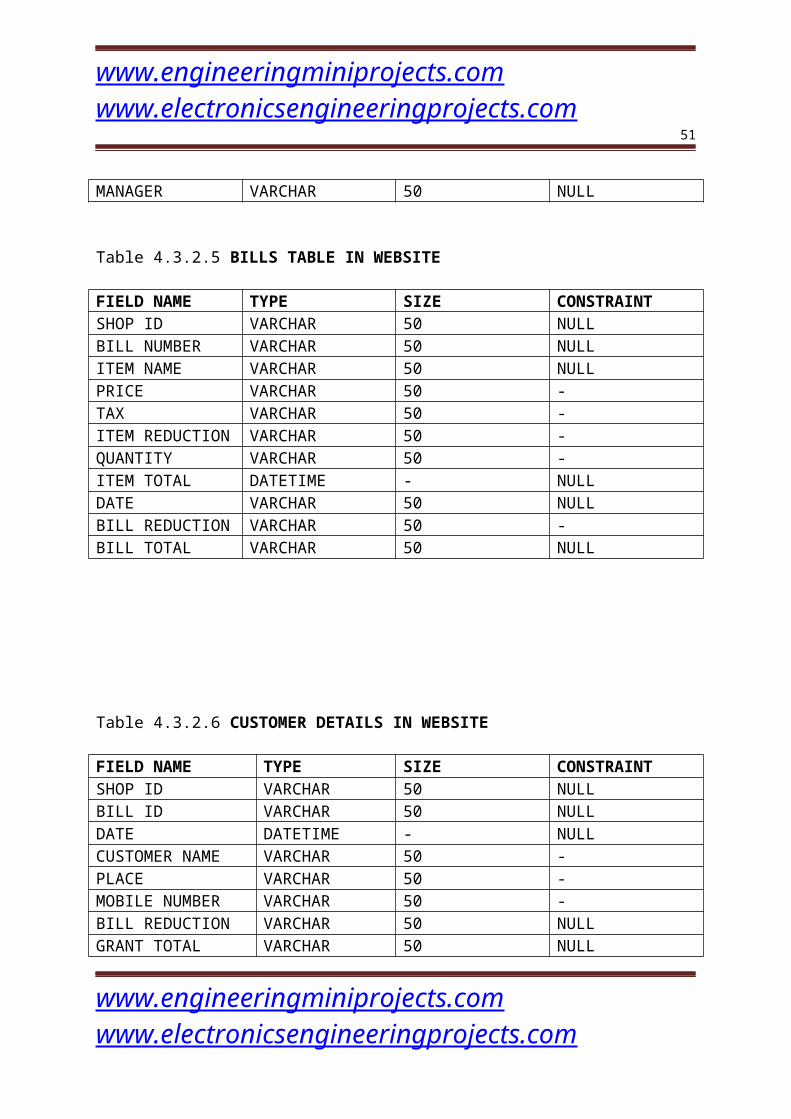
FIELD NAME TYPE SIZE CONSTRAINTSHOP ID VARCHAR 50 NULL, UNIQUESHOP PLACE VARCHAR 50 NULLMANAGER VARCHAR 50 NULL
Table 4.3.2.5 BILLS TABLE IN WEBSITE
FIELD NAME TYPE SIZE CONSTRAINTSHOP ID VARCHAR 50 NULLBILL NUMBER VARCHAR 50 NULLITEM NAME VARCHAR 50 NULLPRICE VARCHAR 50 -TAX VARCHAR 50 -ITEM REDUCTION VARCHAR 50 -QUANTITY VARCHAR 50 -ITEM TOTAL DATETIME - NULLDATE VARCHAR 50 NULLBILL REDUCTION VARCHAR 50 -BILL TOTAL VARCHAR 50 NULL
www.engineeringminiprojects.com www.electronicsengineeringprojects.com
www.engineeringminiprojects.com www.electronicsengineeringprojects.com
36
Table 4.3.2.6 CUSTOMER DETAILS IN WEBSITE
FIELD NAME TYPE SIZE CONSTRAINTSHOP ID VARCHAR 50 NULLBILL ID VARCHAR 50 NULLDATE DATETIME - NULLCUSTOMER NAME VARCHAR 50 -PLACE VARCHAR 50 -MOBILE NUMBER VARCHAR 50 -BILL REDUCTION VARCHAR 50 NULLGRANT TOTAL VARCHAR 50 NULL
www.engineeringminiprojects.com www.electronicsengineeringprojects.com
www.engineeringminiprojects.com www.electronicsengineeringprojects.com
37
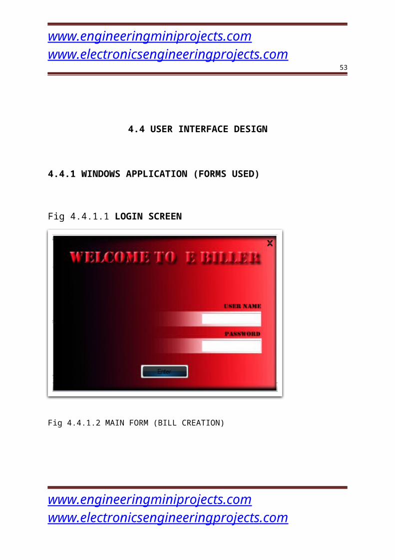
4.4 USER INTERFACE DESIGN
4.4.1 WINDOWS APPLICATION (FORMS USED)
Fig 4.4.1.1 LOGIN SCREEN
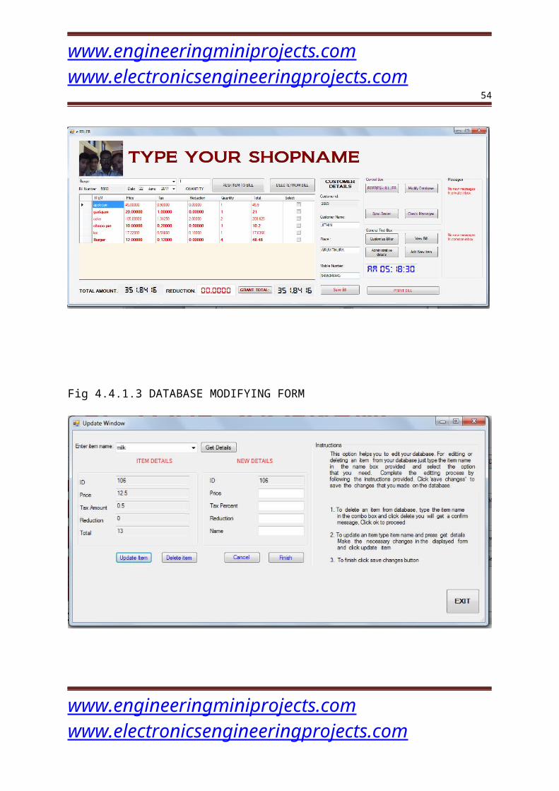
Fig 4.4.1.2 MAIN FORM (BILL CREATION)
www.engineeringminiprojects.com www.electronicsengineeringprojects.com
www.engineeringminiprojects.com www.electronicsengineeringprojects.com
38
Fig 4.4.1.3 DATABASE MODIFYING FORM
4.4.2.E-BILLER WEBSITE
www.engineeringminiprojects.com www.electronicsengineeringprojects.com

www.engineeringminiprojects.com www.electronicsengineeringprojects.com
39
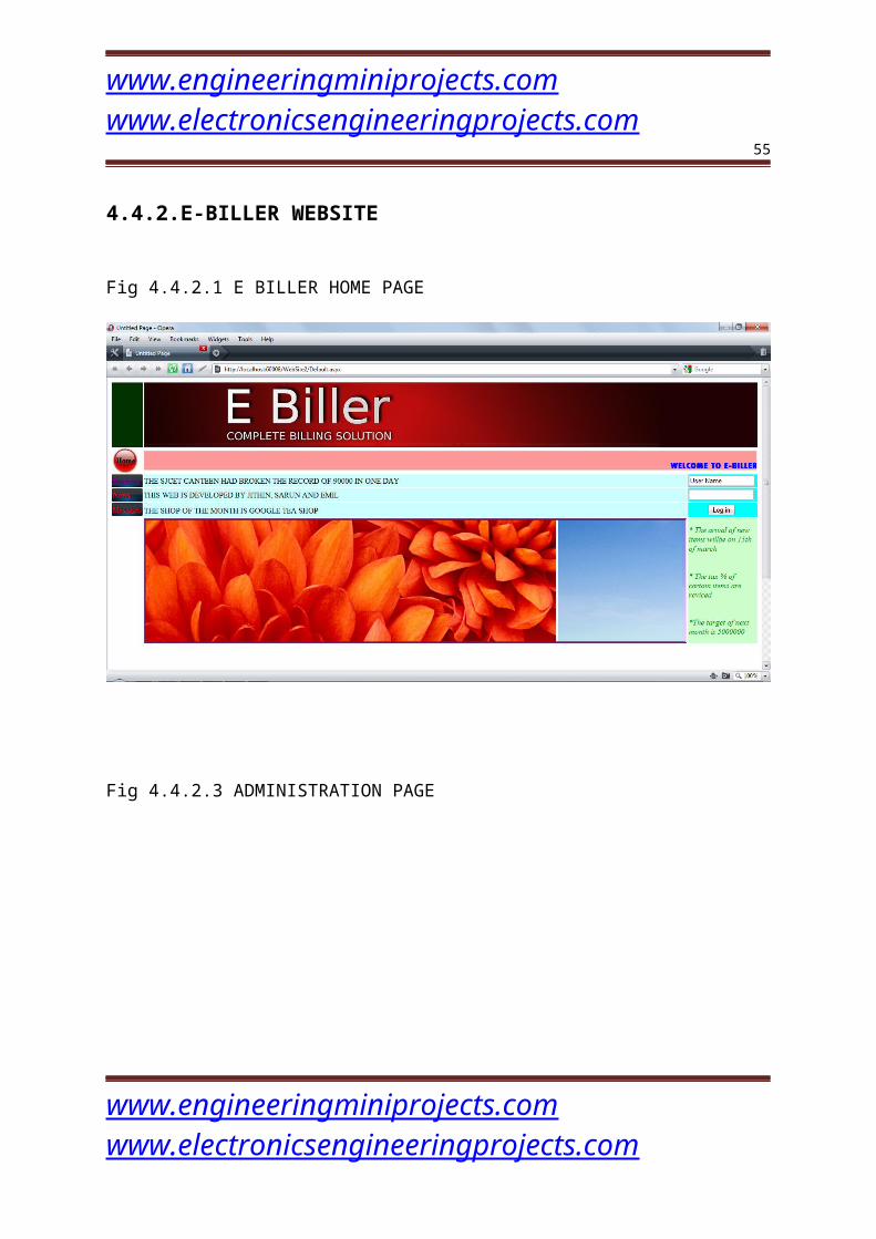
Fig 4.4.2.1 E BILLER HOME PAGE
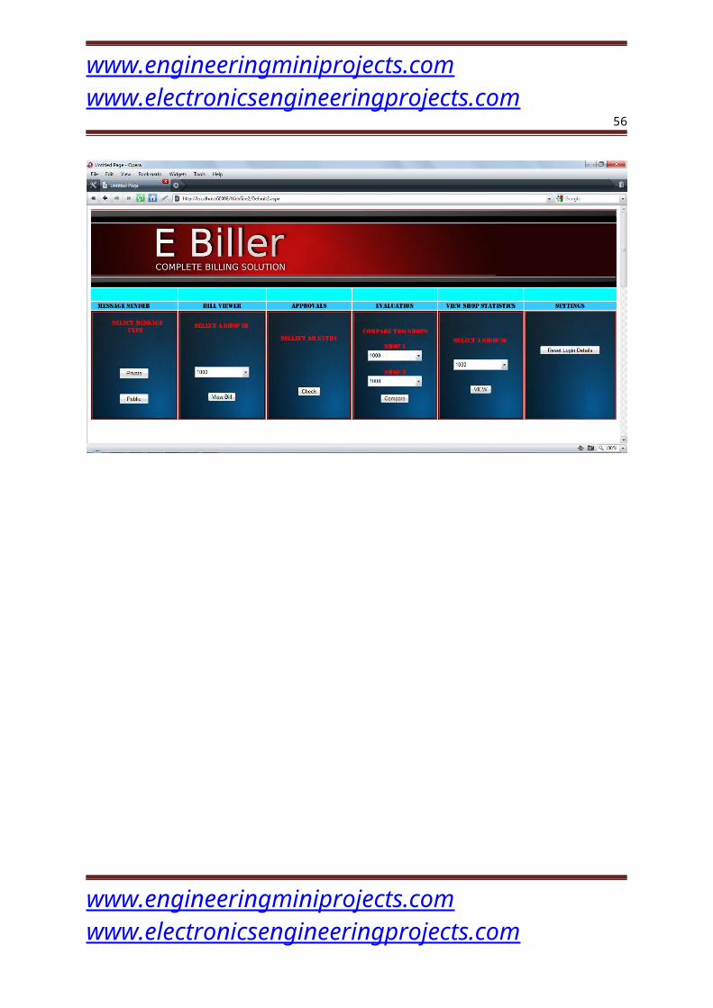
Fig 4.4.2.3 ADMINISTRATION PAGE
www.engineeringminiprojects.com www.electronicsengineeringprojects.com
www.engineeringminiprojects.com www.electronicsengineeringprojects.com
40
5. SYSTEM IMPLEMENTATION
5.1 Implementation Importance:
Implementation is the most important stage in a project
development process. This is the stage where actual system is build according to the
specifications given in SRS and in accordance with the design in DFD. The actual
system is expressed in the language in which we want the software to be built (here it
isC#.net).This is the most complex and difficult task and it has to be done with utmost
care. Care should be taken to write the code in simple, easy to read and write codes.
www.engineeringminiprojects.com www.electronicsengineeringprojects.com
www.engineeringminiprojects.com www.electronicsengineeringprojects.com
41
5.2 Data Structures
Various data structures used for the system are array list, result sets, object,
classes etc. To store various values of an entity at an instant and pass it from function
to function and manipulate it accordingly, result sets are used to store return sets of
values as a result of execution of various SQL query statements. A lot of classes are
essential, especially to establish connection to the database.
5.3 Steps In Working:
E-biller is a multi-branch billing software composed of a windows form
application and a website. Billing is done with the help of windows application and
the monitoring of the shops is done through website. Each branch should register to
the website. Once the shop is registered to the website the shop could send its bills to
the main website database.
This project contains 2 types of users.
Area Manager
Shop Manager
AREA MANAGER
Administrator (Area Manager) can log into the website using his username and
password. Area manager is the onlyone who is allowed to login to the e-biller website,
www.engineeringminiprojects.com www.electronicsengineeringprojects.com
www.engineeringminiprojects.com www.electronicsengineeringprojects.com
42
all the controlling actions could be done from his homepage. Options available in his
website are the following.
Accept newly registered shops.
Area manager’s page is provided with the option to view and approve the newly
registered branches. This is as simple as to button clicks once the registration is
accepted, a unique shop id will be automatically generated which is given to the new
shop to install the e-biller application on the system.
View bills from the branches
Area Manager could view all the bills from all the branches that is saved in the
website database. He could identify each branch separately by using the unique shop
id.
Send Messages
Area manager could broadcast messages to all branches. He could also send private
message to any branch at any time when ever that branch comes online they could
view those messages.
Compare two shops
Area manager could compare two shops just by entering the two shop ids and a button
click. The compare results could be viewed in a highly precise and structured form.
View shop statistics
A shop’s last month statistic is available to area manager in just a single button click.
Settings
All the custom setting of the website and the administrator details could be reset in
this menu.
www.engineeringminiprojects.com www.electronicsengineeringprojects.com
www.engineeringminiprojects.com www.electronicsengineeringprojects.com
43
SHOP MANAGER
Billing
Billing is as simple as selecting the items from the list by typing a few characters of
the item name and pressing the add button. Once an item is added to the list of bill it is
possible to remove that item by selecting and clicking the delete button. Shops could
also save customer details in a billing. All bills are saved in the local database.
View/Edit bill
All bills could be viewed and edited at any time even after it is send to the website
Customize biller
o Customize user interface
E-biller name could be changed at any time. Not only the shop name but
the shop emblem could also be changed anytime
o Customize database
Changes to database are allowed in e-biller. E-biller allows removing;
adding and modifying database are possible in e-biller
Synchronize with the server
Whenever internet facility is available in the shop manager could simply click the
synchronize button to copy all the bills in the local database that are not yet copied to
the main web database.
www.engineeringminiprojects.com www.electronicsengineeringprojects.com
www.engineeringminiprojects.com www.electronicsengineeringprojects.com
44
6. TESTING METHODOLOGY
6.1 Testing objectives
There are several rules that can serve as testing objectives. They are:
Testing is a process of executing a program and finding a bug.
A good test case is one that has a high probability of finding an
undiscovered error.
A successful test is one that uncovers an undiscovered error.
If testing is conducted successfully according to the objectives as stated above, it
would uncover errors in the software. Also testing demonstrates that software
functions appear to be working according to the specification, that performance
requirements appear to have been met.
There are three ways to test a program:
For correctness
For implementation efficiency
For computational complexity
Tests for correctness are meant to verify that a program does exactly what it was
designed to do. This is much more tedious than it may at first appear, especially for
large programs.
Tests of implementation efficiency attempt to find ways to make
correct program faster or use less storage. It is a code-refining process, which re-
examines the implementation phase of algorithm development. Tests for
computational complexity amount to an experimental analysis of the complexity of an
algorithm or an experimental comparison of two or more algorithms, which solve the
same problem.
www.engineeringminiprojects.com www.electronicsengineeringprojects.com
www.engineeringminiprojects.com www.electronicsengineeringprojects.com
45
The following ideas should be a part of any testing plan,
Preventive measures
Spot checks
Testing all part of the program
Test data
Looking for trouble
Time for testing
Re-testing
The three strategies of testing are:
Unit testing
Integration Testing
Validation Testing
6.2 Unit Testing
The testing strategy considers the concept of unit changes. The focus
is on the algorithmic detail of a module and the data flow across the module interface.
Each module is considered as a separate unit. The input given and output generated by
each module is studied individually. Each possibility of input that can be supplied is
considered.
Unit testing focuses verification efforts on the smallest unit of the
software design of the module to check whether each module in the software works
properly so that it gives desired outputs to the given inputs. All validations and
conditions are tested at the module level in the unit test. Boundary condition is tested
to ensure that the module operates at boundaries, establishes that it restricts
processing. All independent paths through the control structure ensure that all
www.engineeringminiprojects.com www.electronicsengineeringprojects.com
www.engineeringminiprojects.com www.electronicsengineeringprojects.com
46
statements in a module have been executed at least once. In conclusion, all errors
handling paths are tested.
The various forms in the project constitute various units and these
units are individually tested to comply with requirements specifications. Exceptional
cases like trying to accessing from an empty table, Validations of textboxes, email-
validity checking, appropriate event handling etc are the various actions done during
the time of unit testing.
6.3 Integration Testing
This testing strategy combines all the modules involved in the
system. After the independent modules are tested, dependent modules that use the
independent modules are tested. This sequence of testing layers of dependent modules
continues until the entire system is constructed.
Though each program individually, they should work after linking them
together. This is referred to as interfacing. Data may be lost across interface and one
module can have an adverse effect on another. Subroutines, after linking, may not
carry out the function expected by the main routine. Integration testing is a systematic
technique for constructing the program structure while at the same time conducting
tests to uncover errors associated with the interface. In the testing, the programs are
constructed and tested in small segments.
In the project integration testing is mainly done to see the
conformity of session variables used in various modules. If a user tries to access a
page without entering through the home page the exception handling mechanism in
www.engineeringminiprojects.com www.electronicsengineeringprojects.com
www.engineeringminiprojects.com www.electronicsengineeringprojects.com
47
the portal generate exception: „Session has expired‟. This is tested during the time of
integration testing.
6.4 Validation Testing
Software testing is defined as the process by which one detects in
the software. It helps to test the correctness, completeness and consistency of the
project. Testing is set activity that can be planned and conducted systematically.
Testing begins at the module level and works towards the integration of the entire
computer-based system.
In the project validation testing is done to see whether the system
conform to requirement specification and design. Here a test-Administrator, test-staffs
and test-client is created and all the operations of the system are carried out like
posting a project, activating the project, mailing, allocation, uploading, viewing the
details etc. This is validated against the requirements stated in SRS.
7. CONCLUSION
7.1 Summary
The aim of the project was to develop a binning system for multi branch shops which
could work both in online mod and offline mod. The scope of the project is that
controlling all the branches by just using a website which makes the controlling
possible from anywhere in the world.
7.2 Limitations
Bill viewing from the website is possible only after synchronization
process. If one branch is not provided with the internet facility that branch could not
synchronize with the server.
www.engineeringminiprojects.com www.electronicsengineeringprojects.com
www.engineeringminiprojects.com www.electronicsengineeringprojects.com
48
7.3 Recommendations for future work
Provide the provision of online shopping in the e-biller website
Area manager could be allowed to access each local database
even if it is not synchronized with the server
Provide stock details of all branches in e-biller application and
thus make it a complete multi branch shop controlling software
8. REFERENCES
Books
[1] Abraham Silberschatz, “Database System Concepts”
[2] Payne Chris, “SAMS teach yourself asp.net in 21 days”
[3] Eric Smith, “ASP.net projects “
[4] Roger S. Pressman, “Software Engineering”
[5] Pankaj Jalote, “Software Engineering”
www.engineeringminiprojects.com www.electronicsengineeringprojects.com
www.engineeringminiprojects.com www.electronicsengineeringprojects.com
49
[6] Ray Rankins, Paul Jensen, Paul Bertucci ”Microsoft SQL Server
Unleashed”
Web sites
[1] www.microsoft.com/msdn
[2] www.w3schools.com
[3] www.codeproject.com
[4] www.planetsourcecode.com
[5] www.c-sharpcorner.com
APPENDIX-A
Software Requirements:
Operating System : Windows XP Professional
www.engineeringminiprojects.com www.electronicsengineeringprojects.com
www.engineeringminiprojects.com www.electronicsengineeringprojects.com
50
Platform : Microsoft .NET
Language : ASP.NET
Web Client : Internet Explorer
Protocol : HTTP
Tools : Microsoft Visual Studio .NET 2008.
Hardware Requirements:
Processor : Intel Pentium IV and above
Hard Disk Space : 40 GB
Display : 15” Color Monitor
Memory : 512MB
Keyboard : 104 Keys
Components : Optical Mouse , fingerprint reader
Database Requirement
MS SQL server 2005
HOW TO USE THE PROGRAM
www.engineeringminiprojects.com www.electronicsengineeringprojects.com
www.engineeringminiprojects.com www.electronicsengineeringprojects.com
51
HOW TO INSTALL
So as to run E-biller you need to install the e-biller application to each branch’s
computer.
Insert the E-biller CD to your CD-ROM drive. It will perform auto run.
Follow the on screen instructions to complete the installation
If auto run does not respond,
Click MY COMUTER>SELECT YOUR CD-ROM DRIVE>DOUBLE CLICK
setup.exe
Now continue the on screen instructions to complete the installation.
The E-biller websiteneeds to be launched with sufficient storage area and an active
server to handle data transactions. Website needs technical assistance to launch. Once
the website is ready each branch should register in the website and should get the
unique code to run the e-biller application. During installation provision to set
username and password is available.
www.engineeringminiprojects.com www.electronicsengineeringprojects.com

www.engineeringminiprojects.com www.electronicsengineeringprojects.com
52
USING THE SOFTWARE
E-BILLER WEBSITE
Fig A.1 E BILLER WELCOME PAGE
In the E-biller website area manager is only allowed to login. New branches could use the provision to register (this do not require login just click in the register link)
Fig A.2 REGESTERING NEW SHOP
www.engineeringminiprojects.com www.electronicsengineeringprojects.com
www.engineeringminiprojects.com www.electronicsengineeringprojects.com
53
Fig A.3 ADMINISTRATIVECONTROLS PAGE
Once you enter the website all control provisions are available in a single page
Fig A.4 SENDING MESSAGES
www.engineeringminiprojects.com www.electronicsengineeringprojects.com
www.engineeringminiprojects.com www.electronicsengineeringprojects.com
54
Sending messages to shops is as simple as entering the message destination and pressing the send button
Fig A.5 VIEW BILL FROM SHOPS
www.engineeringminiprojects.com www.electronicsengineeringprojects.com
www.engineeringminiprojects.com www.electronicsengineeringprojects.com
55
You can view bills from all shops by giving shop id and bill number (could be selected from the provided list)
Fig A.6 COMPARING SHOPS
Comparing to shops is easy as selecting the shops and pressing the “compare shops” button.
Fig A.7VIEW SHOP STATISTICS
www.engineeringminiprojects.com www.electronicsengineeringprojects.com
www.engineeringminiprojects.com www.electronicsengineeringprojects.com
56
Option is available to analyse the performance of a shop in the last calendar month. For using this option you need to enter the shop id and press “View Statistics” button.
Area manager could approve pending registration and provide unique id to new branch in just two button click.
A provision to change login data is also provided in the administrator’s page.
www.engineeringminiprojects.com www.electronicsengineeringprojects.com
www.engineeringminiprojects.com www.electronicsengineeringprojects.com
57
APPENDIX-B
PROGRAM LISTING
www.engineeringminiprojects.com www.electronicsengineeringprojects.com