Embed Size (px)
Citation preview

E-classOperator’s Manual
E 320E 430E 55 AMG
E 300E 320

2
Product informationKindly observe the following in your own best interests:We recommend using Mercedes-Benz original parts as well as conversion parts and accessories explicitly approved by us foryour vehicle model.
We have subjected these parts to a special test in which their reliability, safety and their special suitability for Mercedes-Benzvehicles have been determined.
We are unable to make an assessment for other products and therefore cannot be held responsible for them, even if in individual casesan official approval or authorization by governmental or other agencies should exist. Use of such parts and accessories couldadversely affect the safety performance or reliability of your vehicle. Please do not use them.
Mercedes-Benz original parts as well as conversion parts and accessories approved by us are available at your Mercedes-Benzauthorized dealer where you will receive comprehensive information, also on permissible technical modifications, and whereproper installation will be performed.
Printed in the U.S.A.
We reserve the right to modify the technical details of the vehicle as given in the data and illustrations ofthis Owner's Manual. Reprinting, translation and copying, even of excerpts, is not permitted without ourprior authorization in writing.Press time 09/30/98 MBNA/TI

3
Operator's manual
Our company and staff congratulate you on the purchase of your new Mercedes-Benz.
Your selection of our product is a demonstration of your trust in our company name. Further, it exemplifies your desire to own anautomobile that will be as easy as possible to operate and provide years of service.
Your Mercedes-Benz represents the efforts of many skilled engineers and craftsmen. To ensure your pleasure of ownership, and foryour safety and that of your passengers, we ask you to make a small investment of your time:
• Please read this manual carefully before putting it aside. Then return it to your vehicle where it will be handy for your reference.• Please abide by the recommendations contained in this manual. They are designed to acquaint you with the operation of your
Mercedes-Benz.
We extend our best wishes for many miles of safe, pleasurable driving.
Daimler-Benz Aktiengesellschaft

4
Introduction
This Owner's Manual contains a great deal of useful information. We urge you to read it carefully and familiarize yourself with thevehicle before driving.
For your own safety and longer service life of the vehicle, we urge you to follow the instructions and warnings contained in thismanual. Ignoring them could result in damage to the vehicle or personal injury to you or others. Vehicle damage caused by failure tofollow instructions is not covered by the Mercedes-Benz Limited Warranty.Your vehicle may have some or all of the equipment described in this manual. Therefore, you may find explanations for optionalequipment not installed in your vehicle. If you have any questions about the operation of any equipment, your authorized Mercedes-Benz dealer will be glad to demonstrate the proper procedures.
Owner's Service and Warranty Information
The Owner's Service and Warranty Information Booklet contains detailed information about the warranties covering your Mercedes-Benz, including:
• New Car Limited Warranty,• Emission System Warranty,• Emission Performance Warranty,• California and Massachusetts Emission Control System Warranty (California and Massachusetts only),• State Warranty Enforcement Laws (Lemon Laws).
Important Notice for California Retail Buyers of Mercedes-Benz Automobiles
Under California law you may be entitled to a replacement of your vehicle or a refund of the purchase price, if Mercedes-Benz ofNorth America, Inc. or its authorized dealer fails to conform the vehicle to its express warranties after a reasonable number of repairattempts during the period of one year or 12 000 miles from original delivery of the vehicle. A reasonable number of repair attempts ispresumed for a retail buyer (1) if the vehicle is out of service by reason of repair of substantial nonconformities for a cumulative totalof more than 30 calendar days or (2) the same substantial nonconformity has been subject to repair four or more times and you haveat least once directly notified us in writing of the need to repair the non-conformity and have given us an opportunity to per-form the repair ourselves. Notifications should be sent to the nearest Mercedes-Benz Regional Office listed in the Owner'sService and Warranty Information Booklet.

5
Maintenance
The Service Booklet describes all the necessary maintenance work which should be performed at regular intervals.Always have the Service Booklet with you when you take the vehicle to your authorized Mercedes-Benz dealer for service. Theservice advisor will record each service in the booklet for you.
Roadside Assistance
The Mercedes-Benz Roadside Assistance Program provides factory trained technical help in the event of a breakdown. Calls to thetoll-free Roadside Assistance number:
1-800-FOR MERCedes (in the U.S.A.) 1-800-387-0100 (in Canada)
will be answered by Mercedes-Benz Customer Assistance Representatives 24 hours a day, 365 days a year.For additional information refer to the Mercedes-Benz Roadside Assistance Program brochure in your glove box.
Change of Address or Ownership
If you change your address, be sure to send in the "Change of Address Notice" found in the Owner's Service and WarrantyInformation booklet, or simply call the Mercedes-Benz Customer Assistance Center (in the U.S.A. only) at 1-800-FOR-MERCedes. Itis in your own interest that we can contact you should the need arise.If you sell your Mercedes, please leave all owner's literature with the vehicle to make it available to the next owner.If you bought this vehicle used, be sure to send in the "Notice of Purchase of Used Car" found in the Owner's Service and WarrantyInformation booklet, or call the Mercedes-Benz Customer Assistance Center (in the U.S.A. only) at 1-800-FOR-MERCedes.

6
Operating Your Vehicle Outside the U.S.A. or Canada
If you plan to operate your vehicle in foreign countries, please be aware that:
• service facilities or replacement parts may not be readily available,• unleaded gasoline for vehicles with catalytic converters may not be available; the use of leaded fuels will damage the catalysts,• gasoline may have a considerably lower octane rating, and improper fuel can cause engine damage.
Certain Mercedes-Benz models are available for delivery in Europe under our European Delivery Program. For details, consult yourauthorized Mercedes-Benz dealer or write to:Mercedes-Benz of North America, Inc. European Delivery Department One Mercedes Drive Montvale, NJ 07645In Canada write to:Mercedes-Benz Canada, Inc. European Delivery Department 849 Eglinton Avenue East Toronto, Ontario M4G 2L5
We continuously strive to improve our product, and ask for your understanding that we reserve the right to make changes in designand equipment. Therefore, information, illustrations and descriptions in this Owner's Manual might differ from your vehicle.Optional equipment is also described in this manual, including operating instructions wherever necessary. Since they are special-orderitems, the descriptions and illustrations herein may vary slightly from the actual equipment of your vehicle.If there are any equipment details that are not shown or described in this Owner's Manual, your authorized Mercedes-Benz dealer willbe glad to inform you of correct care and operating procedures.
The Owner's Manual and Service Booklet are important documents and should be kept with the vehicle.

7
The First 1000 Miles (1500 km)
The more cautiously you treat your vehicle during the break-in period, the more satisfied you will be with its performance later on.Therefore, drive your vehicle during the first 1000 miles (1500 km) at moderate vehicle and engine speeds.During this period, avoid heavy loads (full throttle driving) and excessive engine speeds.Avoid accelerating by kickdown. It is not recommended to brake the vehicle by manually shifting to a lower gear. We recommendthat you select positions "3", "2" or "1" only at moderate speeds (for hill driving).After 1000 miles (1500 km) speeds may be gradually increased to the permissible maximum.
Check Regularly and Before a Long Trip
See last page.
Maintenance
Approximately 30 days or 2 000 miles (2 000 km) prior to the next recommended service, the remaining distance or days aredisplayed in the multifunction indicator. See Flexible Service System (FSS) in Index.We strongly recommend that you have your vehicle serviced by your authorized Mercedes-Benz dealer, in accordance with theService Booklet.Failure to have the vehicle maintained in accordance with the Service Booklet may result in vehicle damage not covered by theMercedes-Benz Limited Warranty.
Radio Transmitters
Warning!
Never operate radio transmitters equipped with a built-in or attached antenna (i.e. without being connected to an externalantenna) from inside the vehicle while the engine is running. Doing so could lead to a malfunction of the vehicle's electronicsystem, possibly resulting in an accident and personal injury.
Radio transmitters, such as a portable telephone or a citizens band unit should only be used inside the vehicle if they are connected toan antenna that is installed on the outside of the vehicle.Refer to the radio transmitter operation instructions regarding use of an external antenna.

8
Introduction Front Center Console 28 Combination Switch 55Compartment Ventilation Split Rear Seat 58
Product information 2 Rear Passenger Compartment Adjustable Headlamp Cleaning System 56Operator's manual 4 Air Outlet 28 Exterior Lamp Switch 57Consumer Information 140 Car keys 29 Night Security Illumination 58Problems with your vehicle 141 Start Lock-out 30 Inside Rear View Mirror 58Reporting Safety Defects 142 Infrared Remote Control 30 Exterior Rear View Mirror 59Index 144 Central Locking System 33 Ashtrays 60
Doors 33 Lighter 61Instruments and controls Central Locking Switch 34 Sun Visors 61
Trunk 35 Illuminated Vanity mirrors 61Instruments and controls 10 Power Window and Sliding/Pop-Up Roof 36 Interior Lighting 62Instrument Cluster 12 Anti-Theft Alarm System 37 Storage Compartments 63Indicator Lamp Symbols 13 Power Seats, Front 38 Cup Holder 63Catalytic Converter 15 Multicontour Seat 40 Sliding Roof with Rear Pop-Up Feature 64Starting and Turning Off Heated Seats 41 Power Windows 65
Gasoline Engine 16 Adjusting Steering Wheel 42 Trunk Release Switch 66Diesel Engine 17 Arm Rest, Rear Bench 42 Rear Window Sunshade 66
Driving Instructions 18 First Aid Kit 42 Instrument Lamps 67Head Restraints, Rear 43 Display Illumination 67
Operation Cargo Tie-Down Hooks 43 Trip Odometer 67Shelf below Rear Window 43 Clock 67
Automatic Climate Control 24 Seat belts and Supplemental Restraint Garage Door Opener 68Basic Setting – Automatic Mode 25 system (SRS) 44 Cellular telephone 69Defogging Windows 26 Seat belts 44Defrosting 26 Emergency tensioning retractor (ETR) 48 DrivingRear Window Defroster 26 Airbag 49Air Recirculation 27 Child Restraint 52 Drinking and driving 72Activated Charcoal Filter 27 Steering Lock 54 Parking Brake 72

9
Driving off 72 Traveling Abroad 92 MERCEDES-BENZ Spare Part Service 123Automatic Transmission 73 Layout of Poly-V-Belt Drive 124Cruise Control 77 Practical HintsParking Assist (Parktronic) 91 Technical Data. Fuels,Multifunction Indicator Hood 94 Coolants, Lubricants etc.
Language Selection 79 Checking Coolant Level 95 Consumer InformationMultiple Malfunctions 79 Adding Coolant 95Temporarily Switching off 79 Checking Engine Oil Level 96 Identification Plates 126Defective 79 Bleeding of Diesel Fuel System 96 Vehicle Data Card 127
Charge Indicator Lamp 79 Automatic Trans. Fluid Level 96 Warranty Coverage 127Low Engine Oil Level Warning Lamp 80 Trunk Lamp 97 Technical DataEngine Oil Consumption 80 Spare Wheel, Vehicle Tools, E 300 Diesel 128Fuel Oil Consumption 80 Storage Compartment 97 E 320 130Tachometer 80 Vehicle Jack 98Outside Temperature Indicator 81 Wheels 98 Fuels, Coolants, Lubricants etc. 134Coolant Temperature Gauge 81 Changing Wheels 100 Capacities 134Low Engine Coolant Level Tire in Inflation Pressure 103 Engine Oils 136
Warning Lamp 82 Exterior Lamps 104 Engine Oils Additives 136Low Windshield and Headlamp Battery 109 Air Conditioner Refrigerant 136
Washer Fluid Level Warning Lamp 82 Fuses 111 Brake Fluid 136Exterior Lamp Failure Indicator Lamp 83 Jump Starting 112 Vehicle with Gasoline EngineBrake Pad Wear Indicator Lamp 83 Towing the Vehicle 113 Premium UnleadedBrake Warning 83 Cleaning and Care of the Vehicle 115 Gasoline 137Antilock Brake System (ABS) 84 Testing Infrared Remote Control 119 Fuel Requirements 137Electronic Traction System (ETS) 85 Front Head Restraint 120 Gasoline Additives 137Acceleration Stability Program (ASR) 86 Rear Seat Cushion 121 Vehicle with Diesel EngineElectronic Stability program (ESP) 88 Emergency Operation of Diesel Fuels 138Emission Control 90 Sliding/Pop-Up Roof 121 Coolants 139On-Board Diagnostic System 90 Replacing Wiper Blades Insert 122 Service and Literature 142Winter Driving 91 Manual Release of Fuel Filler Flap 123 Check Regularly Before a Long Trip 147Snow Chains 92 Roof Rack 123

10
Instruments and Controls
For more detailed descriptions see IndexFor adjustment of air outlets, refer to Automatic Climate Control (see Index).
1 Exterior lamp switch 14 Central locking switch Indicator lamp for antitheft alarmsystem
2 Parking brake release 15 Right front seat heater switch
3 Parking brake pedal 16 Glove box (illuminated with key in steering lock position 1 or 2)
4 Hood lock release 17 Automatic climate control, Rear window defroster switchActivated charcoal filter switch
5 Combination switch 18 Radio
6 Cruise control switch 19 Storage/eyeglasses compartment
7 Horn, airbag 20 Ashtray with lighter
8 Instrument cluster 21 ASR or ESP control switch9 Gasoline engine: Steering lock with ignition/starter switch 22 Left power window switch group9 Diesel engine: Steering lock with preglow/starter switch 23 Right power window switch group10 Left front seat heater switch 24 Trunk lid release switch11 Headlamp washer switch 25 Mirror adjustment switch
12 Switch for rear head restraints 26 Switch for rear window sunshade13 Hazard warning flasher switch17 Left front seat heater switch 35 Mirror adjustment switch

11
12
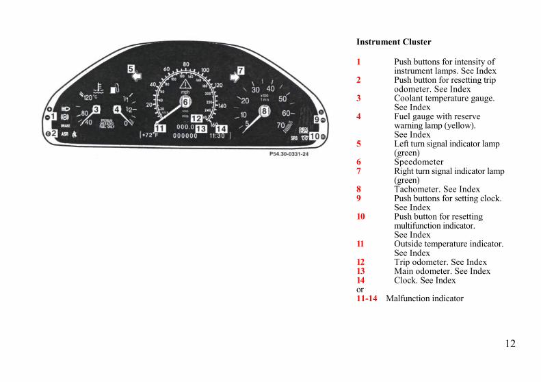
Instrument Cluster
1 Push buttons for intensity ofinstrument lamps. See Index
2 Push button for resetting tripodometer. See Index
3 Coolant temperature gauge.See Index
4 Fuel gauge with reservewarning lamp (yellow).See Index
5 Left turn signal indicator lamp(green)
6 Speedometer7 Right turn signal indicator lamp
(green)8 Tachometer. See Index9 Push buttons for setting clock.
See Index10 Push button for resetting
multifunction indicator.See Index
11 Outside temperature indicator.See Index
12 Trip odometer. See Index13 Main odometer. See Index14 Clock. See Indexor11-14 Malfunction indicator

13
Indicator Lamp SymbolsSymbols and Warnings in the Multifunction Indicator
Brake pads worn down. See Index
Exterior lamp failure. See Index
Engine oil level low. See Index
Coolant level low. See Index
Battery not being charged properly. See Index
Fluid level for windshield and headlamp washer systemlow. See IndexExterior lamps are on. See Index
Take key.Remove electronic key from steering lock.Display defective. See Multifunction Indicator in Index
Multifunction Indicator
If a malfunction occurs, the appropriate warning symbolappears, supplemented by a message in the field normallyoccupied by the displays for outside temperature, odometers,and clock.
In the case of more than one malfunction, symbols andmessages are displayed in sequence. Push reset button (R) forsubsequent messages.
A warning sounds at the beginning of each message.
Notes:
Refer to Multifunction Indicator in the Index for temporarilyswitching off a Warning Symbol and its message.
Warning message selection is available in the English,French, German, Italian, or Spanish language. SeeIndex.
See Multifunction Indicator in IndexMultifunction indicator for several messages.

14
Additional Lamp Symbols in the InstrumentCluster, and Warnings in the Multifunction Indicator
Function Indicator Lamps in the Instrument Cluster
Fasten seat belts. See Index. High beam
Brake fluid low (except Canada). Preglow (Diesel engine only). See Index
Brake fluid low (Canada only).
Parking brake engaged.
ABS malfunction. See Index
ETS malfunction. See Index
SRS malfunction. See
ASR malfunction. See Index
ASR, ESP or ETS.Adjust driving to road condition. See Index
ESP malfunction. See IndexEngine malfunction.If the lamp comes on when the engine is running, itindicates a malfunction of the 02-sensor on Federalversion vehicles, and fuel injection system or emissioncontrol system on the California version vehicles. Ineither case, we recommend that you have the malfunctionchecked as soon as possible. See Index.

15
Catalytic Converter
Your Mercedes-Benz is equipped withmonolithic type catalytic converters, animportant element in conjunction withthe oxygen sensors to achievesubstantial control of the pollutants inthe exhaust emissions. Keep yourvehicle in proper operating conditionby following our recommendedmaintenance instructions as outlined inyour Service Booklet.
Caution!
To prevent damage to the catalyticconverters, use only premium unleadedgasoline in this vehicle.
Any noticeable irregularities in engineoperation should be repaired promptly.Otherwise, excessive unburned fuelmay reach the catalytic convertercausing it to overheat, which couldstart a fire.
Warning!
As with any vehicle, do not idle, parkor operate this vehicle in areas wherecombustible materials such as grass,hay or leaves can come into contactwith the hot exhaust system, as thesematerials could be ignited and cause avehicle fire.

16
Starting and Turning Off the Engine
Before Starting
Ensure that parking brake is engagedand that selector lever is in position "P"or "N". Turn electronic key in steeringlock to position 2.
Cold Engine
Do not depress accelerator. Turn key insteering lock clockwise to the stop.Release key only when the engine isfiring regularly
Hot Engine
Do not depress accelerator. Turn key insteering lock clockwise to the stop. Ifthe engine has not fired after approx. 4seconds, depress accelerator andcontinue cranking until the engine isfiring regularly. Release key and backoff accelerator.
At very high coolant temperatures theengine starting time can be shortened ifthe accelerator is depressed slowly atthe beginning of the starting process.
Turning Off
Turn the electronic key in the steeringlock to position 0 to stop the engine.
The electronic key can only beremoved with your foot off the brakepedal and the selector lever in position"P".
Important!
Due to the installed starter non-repeatfeature, the electronic key must beturned completely to the left beforeattempting to start the engine again.
In areas where temperatures frequentlydrop below -4°F (-20°C) werecommend that an engine block heaterbe installed. Your authorizedMercedes-Benz dealer will advise youon this subject.

17
Starting and Turning Off DieselEngine
Before Starting
Engage parking brake and ensureselector lever is in position "P" or "N".Turn key in steering lock to position 2.
Cold Engine
Turn key to steering lock position 2.Preglow indicator lamp should come on.The preglow process starts. When thepreglow indicator lamp goes out, theengine is ready for starting.
Do not depress accelerator. Turn key insteering lock clockwise to the stop.Release key only when the engine isfiring regularly.
Do not interrupt the starting process, butlimit it to maximum 20 seconds. If theengine is very cold, it is possible that itwill fail to start on subsequent attempts.
Hot Engine
Turn key in steering lock clockwise tothe stop and start engine immediatelywithout depressing the accelerator.
Turning off
Turn the key in the steering lock toposition 0 only when the vehicle hasstopped moving.
The key can only be removed with theselector lever in position "P".
Important!
Due to the installed starter non-repeatfeature, the key must be turnedcompletely to the left before attemptingto start the engine again.
If the preglow indicator lamp fails tolight up, or lights up while driving, thepreglow system is defective and shouldbe repaired at your authorizedMercedes-Benz dealer at the earliestpossible date.
The engine is equipped with a blockheater to provide reliable starting attemperatures below 0°F(-18°C). Referto Winter Driving in Index.

18
Driving Instructions
Warning!
If you feel a sudden significantvibration or ride disturbance, or yoususpect that possible damage to yourvehicle has occurred, you shouldturn on the hazard warning flashers,carefully slow down, and drive withcaution to an area which is a safedistance from the roadway.
Inspect the tires and under thevehicle for possible damage. If thevehicle or tires appear unsafe, have ittowed to the nearest Mercedes-Benzor tire dealer for repairs.
Power Assistance
Warning!
When the engine is not running, thebrake and steering systems arewithout power assistance. Underthese circumstances, a much greatereffort is necessary to stop or steer thevehicle.
Brakes
Warning!
After driving in heavy rain for sometime without applying the brakes orthrough water deep enough to wetbrake components, the first brakingaction may be somewhat reducedand increased pedal pressure may benecessary. Be sure to maintain a safedistance from vehicles in front.
Resting your foot on the brake pedalwill cause excessive and prematurewear of the brake pads.
It can also result in the brakesoverheating thereby significantlyreducing their effectiveness. It maynot be possible to stop the vehicle insufficient time to avoid an accident.
The condition of the parking brakesystem is checked each time thevehicle is in the shop for the requiredservice.
If the parking brake is released and thebrake warning lamp in the instrumentcluster stays on, the brake fluid level inthe reservoir is too low.
Brake pad wear or a leak in the systemmay be the reason for low brake fluidin the reservoir.
Have the brake system inspected at anauthorized Mercedes-Benz dealerimmediately.
All checks and service work on thebrake system should be carried out byan authorized Mercedes-Benz dealer.
Install only brake pads and brakefluid recommended by Mercedes-Benz.
Warning!
If other than recommended brakepads are installed, or other thanrecommended brake fluid is used,the braking properties of the vehiclecan be degraded to an extent thatsafe braking is substantiallyimpaired. This could result in anaccident.

19
Caution!
When driving down long and steepgrades, relieve the load on the brakesby shifting into a lower gear to use theengine's braking power. This helpsprevent overheating of the brakes andreduces brake pad wear.
After hard braking, it is advisable todrive on for some time, rather thanimmediately parking, so the air streamwill cool down the brakes faster.
Tires
Tread wear indicators (TWI) arerequired by law. These indicators arelocated in six places on the treadcircumference and become visible at atread depth of approximately 1/16 in(1.5 mm), at which point the tire isconsidered worn and should bereplaced.
The tread wear indicator appears as asolid band across the tread.
Warning!
Do not allow your tires to wear downtoo far. As tread depth approaches1/16 in (1.5 mm), the adhesionproperties on a wet road are sharplyreduced.
Depending upon the weather and/orroad surface (conditions), the tiretraction varies widely.
Specified tire pressures must bemaintained. This applies particularly ifthe tires are subjected to high loads(e.g. high speeds, heavy loads, highambient temperatures).
Warning!
Do not drive with a flat tire. A flattire affects the ability to steer orbrake the vehicle. You may losecontrol of the vehicle. Continueddriving with a flat tire or driving athigh speed with a flat tire will causeexcessive heat build-up and possiblya fire.
Aquaplaning
Depending on the depth of the waterlayer on the road, aquaplaning mayoccur, even at low speeds and withnew tires. Reduce vehicle speed, avoidtrack grooves in the road and applybrakes cautiously in the rain.

20
Tire Traction
The safe speed on a wet, snow coveredor icy road is always lower than on a dryroad.
You should pay particular attention tothe condition of the road whenever theoutside temperatures are close to thefreezing point.
Warning!
If ice has formed on the road, tiretraction will be substantiallyreduced. Under such weatherconditions, drive, steer and brakewith extreme caution.
We recommend M+S rated radial-plytires for the winter season for all fourwheels to insure normal balancedhandling characteristics. On packedsnow, they can reduce your stoppingdistance as compared with summertires. Stopping distance, however, is stillconsiderably greater than when the roadis not snow or ice covered.
Tire Speed Rating
Your vehicle is factory equipped with"H"-rated tires, which have a Europeanspeed rating of 130 mph (210 km/h).
Despite the tire rating, local speed limitsshould be obeyed. Use prudent drivingspeeds appropriate to prevailingconditions.
Models E 320, E 420: An electronicspeed limiter prevents your vehicle fromexceeding the speed rating.
Warning!
Even when permitted by law, neveroperate a vehicle at speeds greaterthan the maximum speed rating ofthe tires.
Exceeding the maximum speed forwhich tires are rated can lead tosudden tire failure causing loss ofvehicle control and resulting inpersonal injury and possible death.
Parking
Warning!
To reduce the risk of personal injuryas a result of vehicle movement,before turning off the engine andleaving the vehicle always:
1. Keep right foot on brake pedal.2. Firmly depress parking brake
pedal.3. Move the selector lever to
position "P".4. Slowly release brake pedal.5. Turn front wheels towards the
road curb.6. Turn the electronic key to
steering lock position 0 andremove.
Important!
It is advisable to set the parking brakewhenever parking or leaving the vehicle.In addition, move selector lever toposition "P".
When parking on hills, always set theparking brake.

21
Winter Driving Instructions
The most important rule for slippery oricy roads is to drive sensibly and toavoid abrupt acceleration, braking andsteering maneuvers. Do not use thecruise control system under suchconditions.
When the vehicle is in danger ofskidding, move selector lever toposition "N". Try to keep the vehicleunder control by corrective steeringaction.
Road salts and chemicals can adverselyaffect braking efficiency. Increasedpedal force may become necessary toproduce the normal brake effect. Wetherefore recommend depressing thebrake pedal periodically when travelingat length on salt-strewn roads. This canbring road salt impaired brakingefficiency back to normal. Aprerequisite is, however, that this bedone without endangering other driverson the road.
If the vehicle is parked after beingdriven on salt treated roads, the brakingefficiency should be tested as soon aspossible after driving is resumed whileobserving the safety rules in theprevious paragraph.
Warning!
If the vehicle becomes stuck in snow,make sure that snow is kept clear ofthe exhaust pipe and from aroundthe vehicle with engine running.Otherwise, deadly carbon monoxide(CO) gases may enter vehicle interiorresulting in unconsciousness anddeath.
To assure sufficient fresh airventilation, open a window slightlyon the side of the vehicle not facingthe wind.
Passenger Compartment
Warning!
Always fasten items being carried assecurely as possible.
In an accident, during hard brakingor sudden maneuvers, loose itemswill be thrown around inside thevehicle, and cause injury to vehicleoccupants unless the items aresecurely fastened in the vehicle.

22

23
Operation

24
Automatic Climate Control
The system is always at operationalreadiness, except when manuallyswitched off.
The automatic climate control onlyoperates with the engine running.
The temperature selector should be leftat the desired temperature setting. Thetemperature selected is reached asquickly as possible.
The system will not heat or cool anyquicker by setting a higher or lowertemperature.
1 Air volume control for center airoutlets, turn wheel up to open.
2 Air volume control for side airoutlet.To open air outlets: Turnwheel to position .
3 To open defroster outlets: Turnwheel to position
4 Center air outlet, adjustable5 Side air outlet, adjustable6 Side defroster outlets7 Display and Controls
The automatic climate control removesconsiderable moisture from the airduring operation in the cooling mode.It is normal for water to drip on theground through ducts in the underbody.
The desired interior temperature can beselected separately for the left and rightside of the passenger compartment.

25
Display and Controls
Press the desired button to activate,indicator lamp is on while activated.
Automatic mode
Raise temperature
Lower temperature
Defrost
Air recirculation
Activated charcoal filter
Rear window defroster
Air distribution, manual
Economy mode
Air volume, manual
Residual engine heatutilization.
Basic Setting - Automatic Mode
Press left and right button forautomatic mode.
Simultaneously press both andbuttons for temperature setting of
72°F.
Air volume and distribution arecontrolled automatically.
This setting can be used all yeararound.
Economy
The function of this setting correspondsto the automatic mode. However,because the air conditioningcompressor will not engage (fuelsavings), it is not possible to aircondition in this setting.
Press button to activate.
Press button once again to returnto previous setting.
26
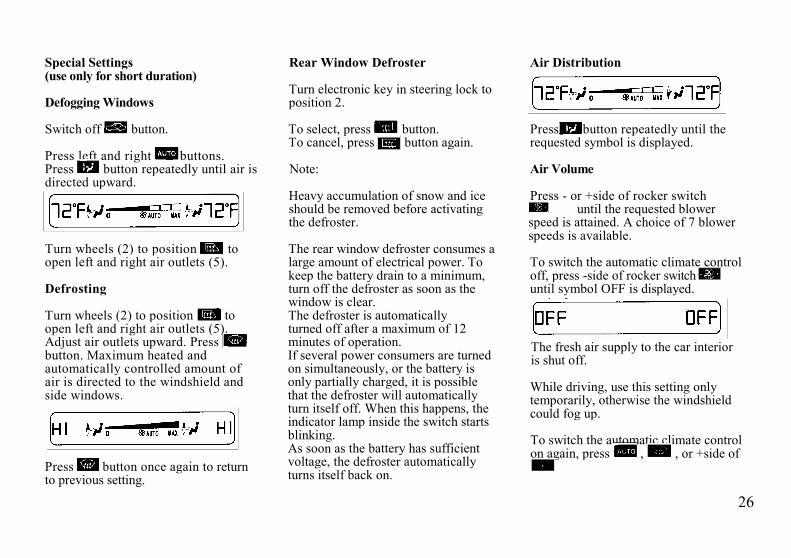
Special Settings(use only for short duration)
Defogging Windows
Switch off button.
Press left and right buttons.Press button repeatedly until air isdirected upward.
Turn wheels (2) to position toopen left and right air outlets (5).
Defrosting
Turn wheels (2) to position toopen left and right air outlets (5).Adjust air outlets upward. Pressbutton. Maximum heated andautomatically controlled amount ofair is directed to the windshield andside windows.
Press button once again to returnto previous setting.
Rear Window Defroster
Turn electronic key in steering lock toposition 2.
To select, press button.To cancel, press button again.
Note:
Heavy accumulation of snow and iceshould be removed before activatingthe defroster.
The rear window defroster consumes alarge amount of electrical power. Tokeep the battery drain to a minimum,turn off the defroster as soon as thewindow is clear.The defroster is automaticallyturned off after a maximum of 12minutes of operation.If several power consumers are turnedon simultaneously, or the battery isonly partially charged, it is possiblethat the defroster will automaticallyturn itself off. When this happens, theindicator lamp inside the switch startsblinking.As soon as the battery has sufficientvoltage, the defroster automaticallyturns itself back on.
Air Distribution
Press button repeatedly until therequested symbol is displayed.
Air Volume
Press - or +side of rocker switchuntil the requested blower
speed is attained. A choice of 7 blowerspeeds is available.
To switch the automatic climate controloff, press -side of rocker switchuntil symbol OFF is displayed.
The fresh air supply to the car interioris shut off.
While driving, use this setting onlytemporarily, otherwise the windshieldcould fog up.
To switch the automatic climate controlon again, press , , or +side of

27
Air Recirculation
This mode can be selected to temporarilyreduce the entry of annoying odors ordust into the vehicle's interior.Outside air is not supplied to the car'sinterior.
To select, press button.To cancel, press button again.The system will automatically switchfrom recirculated air to fresh air
• after approx. 5 minutes at outsidetemperatures below approx. 40°F(5°C),
• after approx. 30 minutes, at outsidetemperatures above approx. 40°F(5°C),
• after approx. 5 minutes, if buttonis pressed.
If the windows should fog up from theinside, switch from recirculated air backto fresh air.
At high outside temperatures, the systemautomatically engages the recirculatedair mode thereby increasing the coolingcapacity performance, switching topartially fresh air within 20 minutes.
Dust Filter
Nearly all dust particles and pollen arefiltered out before outside air enters thepassenger compartment through the airdistribution system.
Note:
Do not obstruct the air flow by keepingthe air intake grille in front ofwindshield free of snow and debris.
Also keep the air intake grille in front ofwindshield free of snow and debris.
Activated Charcoal Filter
To select, press button.To cancel, press button again.
An activated charcoal filter markedlyreduces bad odors and re movespollutants from the air entering thepassenger compartment.
The blower speed is slightly increasedto supply a contant volume of air.The system switches automatically tothe air recirculation mode, if the carbonmonoxide (CO) or nitric oxide (NO ofthe outside air increases.
When pressing button or ‚the filter is also switched oft.
Notes:
The automatic air recirculation does notfunction when selecting the Economymode ‚ or the outside temperatureis below45°F (7°C).The activated charcoal filter should beswitched oft when windows fog up onthe inside, or if the passengercompartment needs to be quickly heatedor cooled down.

28
Residual Engine Heat Utilization
With the engine switched off, it ispossible to continue heating the interiorfor a short while.
Air volume and distribution arecontrolled automatically.
To select:
Turn electronic key in steering lock toposition 1 or 0 or remove key.
Press button.
This function selection will not activateif the battery charge level is insufficient.
To cancel: Press button.
The system will automatically shut off
• if you turn electronic key insteering lock to position 2,
• after approx. 30 minutes,• if the battery voltage drops.
Front Center ConsoleCompartment Ventilation
The front center console compartmenthas its own air outlet.
To open: Push lever down.To close: Push lever up.
The air volume is dependent on thesetting of the
• air volume control• air distribution control• air outlets in the dashboard and
rear passenger compartment.
The air temperature is about the samethan that of the dashboard air outlets. Itcannot be regulated separately.
Note:
The compartment can get very warmdue to its confined space. When storingheat sensitive objects in thecompartment, close the air outlet whileheating the passenger compartment.Also, do not obstruct the air outlet.
Rear Passenger CompartmentAdjustable Air Outlet
To open air outlet, rotate wheel (1)upward.The air outlet is adjustable.
Important!
This vehicle is equipped with an airconditioner system that uses R-134a(HFC: ozone-friendlyhydrofluorocarbon) as a refrigerant.Repairs should always be performedby a qualified technician, andrefrigerant should be collected in arecovery system for recycling.

29
Car Keys
Included with your vehicle are:
• 2 Infrared remote controlswith folding master keys,
• 1 Valet key,• 1 Flat key.
Infrared Remote Control with FoldingMaster Key
The master key fits all locks on the car.
To release the key, press button (1).The key unfolds from the holder byitself.
The transmitter for the infrared remotecontrol is located in the key holder, thereceivers are located on the inside rearview mirror, in the driver's door handle,and next to the trunk lock.
The valet key works only in the frontpassenger door lock and the steeringlock.
The valet key will not work in the trunkand storage compartments locks.
The flat key fits all locks on the car.
Notes:
Do not give the master key to anunauthorized person.
We recommend that you carry the flatkey with you and keep it in a safe place(e.g. your wallet) so that it is alwayshandy. Never leave the flat key in thevehicle.
Warning!
When leaving the vehicle alwaysremove the key from the steeringlock. Do not leave childrenunattended in the vehicle.Unsupervised use of vehicleequipment may cause seriouspersonal injury.
Obtaining Replacement Keys
Your vehicle is equipped with a theftdeterrent locking system requiring aspecial key manufacturing process. Forsecurity reasons, replacement keyscan only be obtained from yourauthorized Mercedes-Benz dealer.

30
Starter Lock-Out
Important!
Removing the key from the steeringlock activates the start lock-out. Theengine cannot be started.
Turning the key in the steering lock toposition 2 deactivates the start lock-out.
Infrared Remote Control
The vehicle doors, trunk and fuel fillerflap can be centrally locked andunlocked, as well as the windows andsliding roof closed with infrared remotecontrol.
With vehicle centrally locked, the trunkcan also be opened by using the infraredremote control. Aim transmitter eye atreceiver and press transmit button twice.
1 Transmit button
2 Transmitter eye andbattery check
3 Key release button

31
4 Receiver on inside rear viewmirror
5 Red indicator lamp(locking)
6 Green indicator lamp(unlocking)
7 Receiver, red indicator lamp(locking) and green indicator lamp(unlocking) in driver's door handle.
8 Receiver, red indicator lamp(locking) and green indicator lamp(unlocking) next to trunk lock.

32
Locking and Unlocking
Aim transmitter eye (2) at areceiver (4, 7 or 8) and presstransmit button.
The red or green indicator lamp on thereceiver should blink. It stops blinkingwhen the vehicle is properly locked orunlocked.
Notes:
If the trunk was previously lockedseparately, it will remain locked (seeIndex).
If the vehicle cannot be locked orunlocked by pressing the transmitbutton, then it may be necessary tochange the batteries in the transmitter(if ok, battery indicator lamp intransmitter will light briefly whentransmitting) or to synchronize thesystem, see Remote Control, Infrared inIndex.
Closing Windows and Sliding/ Pop-Up Roof from Outside
Continue to press transmit button afterlocking car.
The windows and sliding/pop-up roofbegin to close after approx. 2 seconds.
Warning!
Never close the windows orsliding/ppp-up roof if there is thepossibility of anyone being harmedby the closing procedure.
In case the closing procedure causespotential danger, the closingprocedure can be immediatelyreversed by releasing and pressingthe remote control button again untilthe green indicator lamp at thereceiver blinks. The sliding/pop-uproof and windows will open again.The sliding/pop-up roof will onlyopen if it was not fully closed.
Note:
If the side windows and sliding/ pop-up roof cannot be closed automaticallyby pressing the transmit button of theinfrared remote control then it may benecessary to change the batteries in thetransmitter (if ok, battery indicatorlamp in transmitter will light brieflywhen transmitting), or to synchronizethe system, see Remote Control,Infrared in Index.

33
Central Locking System
The entire vehicle may be locked orunlocked by either using the master keyin the door or trunk locks, or centrallocking switch located in centerconsole. The central locking system alsolocks or unlocks the fuel filler flap.
Note:
If the fuel filler flap cannot be opened,refer to Fuel Filler Flap, ManualRelease (see Index).
Doors
1 Opening - pull handle2 Unlocking3 Locking4 Individual door from inside:
• Push lock button down to lock.• Pull lock button up to unlock.
When you lock the car, all door lockbuttons should move down. If any onestays up, the respective door is notproperly closed.
You should then unlock the car, openand reclose this door, and lock the caragain. Each individual door can belocked with door lock button - thedriver's door can only be locked when itis closed.
If the car has previously been lockedfrom the outside, only the door beingopened from the inside will unlock, andthe alarm will come on. The remainingdoors, the trunk lid and fuel filler flapremain locked.

34
Central locking switch
1 Locking2 Unlocking
The central locking switch is located onthe center console.
The doors can only be locked with thecentral locking switch, if the front doorsare closed.
The doors cannot be unlocked with thecentral locking switch, if car waspreviously locked with the remotecontrol.
If the car has previously been lockedwith the central locking switch, only theopened door is unlocked.
35
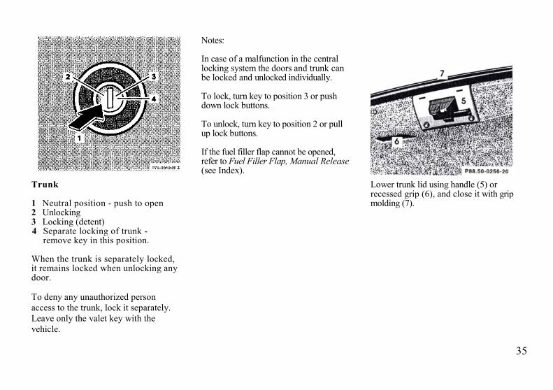
Trunk
1 Neutral position - push to open2 Unlocking3 Locking (detent)4 Separate locking of trunk -
remove key in this position.
When the trunk is separately locked,it remains locked when unlocking anydoor.
To deny any unauthorized personaccess to the trunk, lock it separately.Leave only the valet key with thevehicle.
Notes:
In case of a malfunction in the centrallocking system the doors and trunk canbe locked and unlocked individually.
To lock, turn key to position 3 or pushdown lock buttons.
To unlock, turn key to position 2 or pullup lock buttons.
If the fuel filler flap cannot be opened,refer to Fuel Filler Flap, Manual Release(see Index).
Lower trunk lid using handle (5) orrecessed grip (6), and close it with gripmolding (7).

36
Power Windows and Sliding/Pop-UpRoof
1 Opening2 Interrupting3 Closing
When locking doors or trunk, turnmechanical key in door lock or trunklock to position 3 and hold. Thewindows begin to close automaticallyafter approximately 1 second.
To interrupt the closing procedure,turn mechanical key to position 2.
Warning!
Never close the windows orsliding/ppp-up roof if there is thepossiblity of anyone being harmedby the closing procedure.
In case the closing procedure causespotential danger, the closingprocedure can be immediatelyreversed by turning the key to theunlocking position (3) within 10seconds. The sliding/pop-up roof andwindows will open again. Thesliding/pop-up roof will only open ifit was not fully closed.
Note:
If the closing procedure is interrupted, itcan only be continued by first turningthe key to the unlocked position (3) andthen again to the locking position (1) andhold.

37
1 Indicator lamp in switch located incenter console
Antitheft Alarm System
The antitheft alarm is automaticallyarmed or disarmed with the remotecontrol or any of your vehicle'smechanical keys by locking orunlocking the driver's door or thetrunk.
A blinking lamp (1) indicates thatthe alarm is armed.
The antitheft alarm is disarmedwhen unlocking the front passengerdoor or the trunk with any of yourvehicle's keys or infrared remotecontrol
Operation:
Once the alarm system has been armed,the exterior vehicle lamps will flash andan alarm will sound when someone:
• opens a door,• opens the trunk,• opens the hood,• switches on or bridges the
ignition circuit,• steps on the brake pedal.
The alarm will last approximately 21/2minutes in the form of flashing exteriorlamps. At the same time an alarm willsound for 30 seconds. The alarm willstay on even if the activating element(a door, for example) is immediatelyclosed.
Note:
We recommend that you carry theelectronic reserve key plus mechanicalkey with you and keep it in a safe place(e.g. your wallet) so that it is alwayshandy. Never leave the electronicreserve key in the vehicle.
38
Power Seats, Front
Warning!
Do not adjust the driver's seat whiledriving. Adjusting the seat whiledriving could cause the driver to losecontrol of the vehicle.
Never ride in a moving vehicle withthe backrest reclined. Sitting in anexcessively reclined position can bedangerous. You could slide under theseat belt in a collision. If you slideunder it, the belt would apply forceat the abdomen or neck. That couldcause serious or even fatal injuries.The backrest and seat belt providethe best restraint when the wearer isin an upright position and the belt isproperly positioned on the body.
Never place hands under seat or nearany moving parts while a seat isbeing adjusted.
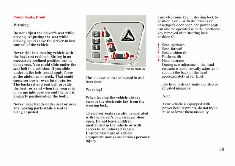
The slide switches are located in eachfront door.
Warning!
When leaving the vehicle alwaysremove the electronic key from thesteering lock.
The power seats can also be operatedwith the driver's or passenger dooropen. Do not leave childrenunattended in the vehicle or withaccess to an unlocked vehicle.Unsupervised use of vehicleequipment may cause serious personalinjury.
Turn electronic key in steering lock toposition 1 or 2 (with the driver's orpassenger's door open, the power seatscan also be operated with the electronickey removed or in steering lockposition 0).
1 Seat, up/down2 Seat, fore/aft3 Seat cushion tilt4 Backrest tilt5 Head restraint
During seat adjustment, the headrestraint is automatically adjusted tosupport the back of the headapproximately at ear level.
The head restraint angle can also beadjusted manually.
Note:
Your vehicle is equipped withpower head restraints, do not try toraise or lower them manually.
39
Synchronizing Head Restraints
If the power supply was interrupted(battery disconnected or empty), thepower seats and head restraints are nolonger adjusted automatically.
To resynchronize the adjustmentfeature, move the seat completelyforward and the head restraint fullydown.
Caution!
Do not remove head restraints exceptwhen mounting seat covers. Forremoval refer to Head Restraints,Front, see Index. Whenever restraintshave been removed be sure to reinstallthem before driving.
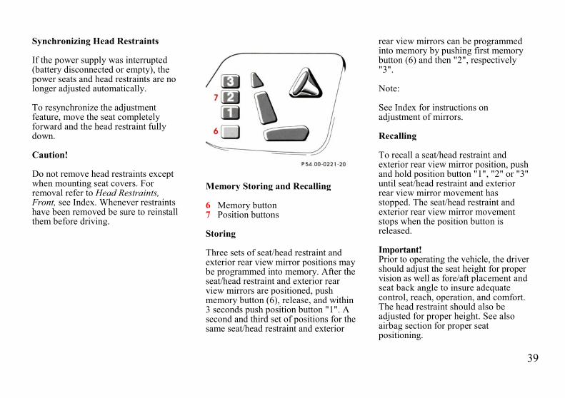
Memory Storing and Recalling
6 Memory button7 Position buttons
Storing
Three sets of seat/head restraint andexterior rear view mirror positions maybe programmed into memory. After theseat/head restraint and exterior rearview mirrors are positioned, pushmemory button (6), release, and within3 seconds push position button "1". Asecond and third set of positions for thesame seat/head restraint and exterior
rear view mirrors can be programmedinto memory by pushing first memorybutton (6) and then "2", respectively"3".
Note:
See Index for instructions onadjustment of mirrors.
Recalling
To recall a seat/head restraint andexterior rear view mirror position, pushand hold position button "1", "2" or "3"until seat/head restraint and exteriorrear view mirror movement hasstopped. The seat/head restraint andexterior rear view mirror movementstops when the position button isreleased.
Important!Prior to operating the vehicle, the drivershould adjust the seat height for propervision as well as fore/aft placement andseat back angle to insure adequatecontrol, reach, operation, and comfort.The head restraint should also beadjusted for proper height. See alsoairbag section for proper seatpositioning.

40
head restraint should also be adjustedfor proper height.
Both the inside and outside rear viewmirrors should be adjusted for adequaterearward vision.
Fasten seat belts. Infants and smallchildren should be seated in a properlysecured restraint system that complieswith U.S. Federal Motor VehicleSafety Standard 213 and CanadianMotor Vehicle Safety Standard 213.
All seat, head restraint, steering wheel,and rear view mirror adjustments aswell as fastening of seat belts should bedone before the vehicle is put intomotion.
Multicontour Seat (optional)
1 Seat cushion depth2 Backrest bottom3 Backrest center4 Side bolster adjustment
Some models may be equipped withmulticontour seats. These seats havemovable seat cushions, and inflatable aircushions built into the backrest toprovide additional lumbar and sidesupport.
The seat cushion movement andamount of backrest cushion height andcurvature can be continuously variedwith regulators (1, 2 and 3) afterturning the electronic key in steeringlock to position 2.
The side bolsters of the backrest can beadjusted with rocker switch (4):
• press down forward end -increase side support,
• press down rearward end -decrease side support.
If the engine is turned off, the lastcushion setting is retained in memory,and automatically adjusts the cushionto this setting when the engine isrestarted.
41
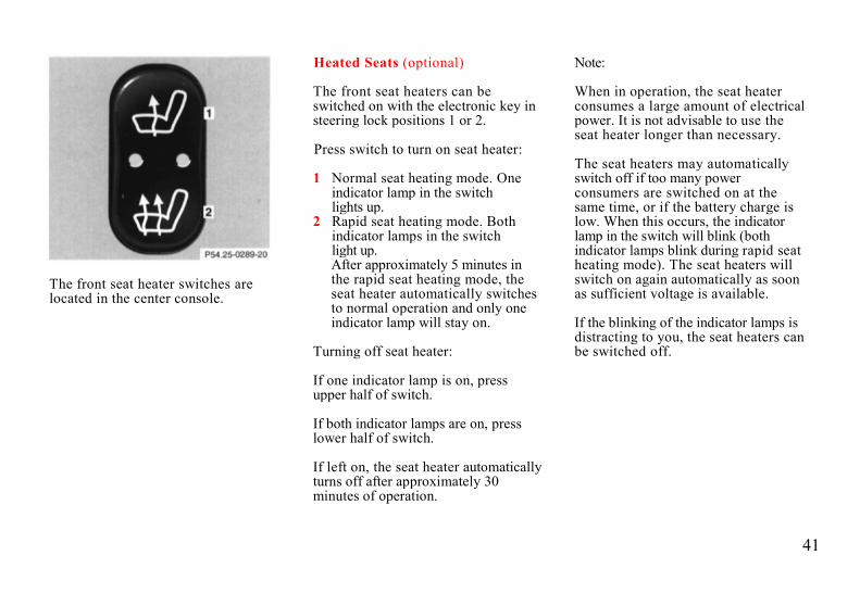
The front seat heater switches arelocated in the center console.
Heated Seats (optional)
The front seat heaters can beswitched on with the electronic key insteering lock positions 1 or 2.
Press switch to turn on seat heater:
1 Normal seat heating mode. Oneindicator lamp in the switchlights up.
2 Rapid seat heating mode. Bothindicator lamps in the switchlight up.After approximately 5 minutes inthe rapid seat heating mode, theseat heater automatically switchesto normal operation and only oneindicator lamp will stay on.
Turning off seat heater:
If one indicator lamp is on, pressupper half of switch.
If both indicator lamps are on, presslower half of switch.
If left on, the seat heater automaticallyturns off after approximately 30minutes of operation.
Note:
When in operation, the seat heaterconsumes a large amount of electricalpower. It is not advisable to use theseat heater longer than necessary.
The seat heaters may automaticallyswitch off if too many powerconsumers are switched on at thesame time, or if the battery charge islow. When this occurs, the indicatorlamp in the switch will blink (bothindicator lamps blink during rapid seatheating mode). The seat heaters willswitch on again automatically as soonas sufficient voltage is available.
If the blinking of the indicator lamps isdistracting to you, the seat heaters canbe switched off.

42
Adjustable Steering Wheel
Turn electronic key in steering lock toposition 1 or 2 (with the driver's orfront passenger's door open, thesteering wheel can also be operatedwith the electronic key removed or insteering lock position 0).
To lengthen or shorten the steeringcolumn, push switch foreward orbackward.
To raise or lower steering wheel, pushswitch up or down.
Note:
The steering wheel position can bestored in memory together with theseat/head restraint and exterior rearview mirror positions, see Index.
Warning!
Do not adjust the steering wheelwhile driving. Adjusting thesteering wheel while driving couldcause the driver to lose control ofthe vehicle
Armrest, Rear Bench
Pull down the armrest by its top.
Cup Holder in Rear Bench Armrest
Briefly press drawer (1) and pull out toits detent.
First Aid Kit in Rear Bench Armrest
Press button (1) and pull drawer out toits final stop.

43
Head Restraints, Rear
Folding head restraints backward (withengine running):Press symbol-side of rocker switch torelease the head restraints. The headrestraints will then fold backward forincreased visibility.
Placing head restraints upright:Pull head restraint forward until it locks inposition.Inclination of head restraints:The head restraint inclination can beadjusted manually.
Important!
For safety reasons, always drive withthe rear head restraints in the uprightposition when the rear seats areoccupied.Keep area around head restraints clearof articles (e.g. clothing) to not obstructthe folding operation of the headrestraints.
Cargo Tie-Down Hooks
Inside the trunk are four cargo tie-downhooks.
Secure cargo by applying even load onall four hooks.
Shelf below Rear Window
Warning!
The shelf below the rear windowshould not be used to carry objects.This will prevent such objects frombeing thrown about and injuringvehicle occupants during an accidentor sudden maneuver.

44
Seat Belts and SupplementalRestraint System (SRS)
Your vehicle is equipped with seatbelts for all seats, emergencytensioning retractors for the front seatbelts, as well as front and side impactairbags and knee bolsters for driver andfront passenger.
Seat Belts
Important!
Laws in most states and all Canadianprovinces require seat belt use.
All states and provinces require use ofchild restraints that comply with U.S.Federal Motor Vehicle Safety Standard213 and Canadian Motor VehicleSafety Standard 213.
We strongly recommend their use
Warning!
Never ride in a moving vehicle withthe backrest reclined. Sitting in anexcessively reclined position can bedangerous. You could slide under theseat belt in a collision. If you slideunder it, the belt would apply forceat the abdomen or neck. That couldcause serious or even fatal injuries.The backrest and seat belt providethe best restraint when the wearer isin an upright position and the belt isproperly positioned on the body.
Seat Belt Warning System
With the electronic key in steeringlock position 2, a warning sounds for ashort time if the driver's seat belt is notfastened.
Warning!
Failure to wear and properly fastenand position your seat belt greatlyincreases your risk of injuries andtheir likely severity in an accident.You and your passengers shouldalways wear seat belts.
If you are ever in an accident, yourinjuries can be considerably moresevere without your seat beltproperly buckled. Without your seatbelt buckled, you are much morelikely to hit the interior of the vehicleor be ejected from it. You can beseriously injured or killed.
In the same crash, the possibility forinjury or death is lessened with yourseat belt buckled.

45
Fastening of Seat Belts
1 Latch plate2 Buckle3 Release button4 Button for belt outlet height
adjustment
Push latch plate (1) into buckle (2) untilit clicks. Do not twist the belt. A twistedseat belt may cause injury.
The lap belt should be positioned as lowas possible on your hips and not acrossthe abdomen
Tighten the lap portion to a snug fit bypulling shoulder portion up.
The shoulder portion of the seat beltmust be pulled snug and checked forsnugness immediately after engagingit.
Adjust seat belt so that shoulderportion is located as close as possibleto the middle of your shoulder (itshould not touch the neck). For thispurpose, you can adjust the beltheight. Five positions are available
Raising:Slide belt outlet upward.
Lowering:Press button (4) and slide belt outletdownward.
For safety reasons, avoid adjustingthe seat or seat back into positionswhich could affect the correct seatbelt position.
Note:
For cleaning and care of the seatbelts, see Cleaning and Care of theVehicle in Index.

46
Unfastening of Seat Belts
Push the release button (3) in the beltbuckle (2).
Allow the retractor to completely rewindthe seat belt by guiding the latch plate(1).
Operation:
The inertia reel stops the belt fromunwinding during sudden vehicle stopsor when quickly pulling on the belt.The locking function of the reel may bechecked by quickly pulling out the belt.
Warning!
USE SEAT BELTS PROPERLY.
• Each occupant should weartheir seat belt at all times,because seat belts help reducethe likelihood of and potentialseverity of injuries in accidents,including rollovers. "SRS"(driver airbag, front passengerairbag, side impact airbags),"ETR" (seat belt emergencytensioning retractors), and kneebolsters are designed toenhance the protection offeredto properly belted occupants incertain frontal impacts whichexceed preset deploymentthresholds.
• Improperly positioned seatbelts do not provide maximumprotection and may causeserious injuries in case of anaccident.
• Never wear the shoulder beltunder your arm, against yourneck or off your shoulder. In acrash, your body would move toofar forward. That would increasethe chance of head and neckinjuries. The belt would also
apply too much force to the ribsor abdomen, which couldseverely injure internal organssuch as your liver or spleen.
• Position the lap belt as low aspossible on your hips and notacross the abdomen. If the belt ispositioned across yourabdomen, it could cause seriousinjuries in a crash.
• Each seat belt should never beused for more than one personat a time. Do not fasten a seatbelt around a person andobjects.
• Belts should not be worntwisted. In a crash, you wouldn'thave the full width of the belt totake impact forces. The twistedbelt against your body couldcause injuries.
• Pregnant women should also usea lap-shoulder belt. The lap beltportion should be positioned aslow as possible on the hips toavoid any possible pressure onthe abdomen.

47
Warning!
USE CHILD RESTRAINTSPROPERLY.
• Infants and small children mustbe seated in an infant or childrestraint system, which isproperly secured by a lap belt orlap belt portion of a lap-shoulderbelt. Children could be en-dangered in an accident if theirchild restraints are not properlysecured in the vehicle.
• Rear-facing child restraints mustnot be used in the front seat.They could be struck by theairbag when it inflates in a crash.If this happens, a child in therestraint could be seriously orfatally injured.
• According to accident statistics,children are safer when properlyrestrained in the rear seatingpositions than in the front seatingpositions.
• Children too big for child restraintsystems should ride in rear seatsusing regular seat belts. Positionshoulder belt across chest andshoulder, not face or neck. Abooster seat may be necessary toachieve proper belt positioning.
• Adjust the front passenger seat asfar as possible rear ward from thedashboard when a child restraintis installed.
Supplemental Restraint System(SRS)
The term SRS means that airbags areintended as a supplement to seat belts.Airbags alone cannot protect as well asairbags plus seat belts in impacts forwhich the air-bags were designed tooperate, and do not afford anyprotection whatsoever in crashes forwhich the system is not designed todeploy.The SRS uses two crash severity levels(thresholds) to activate either theEmergency Tensioning Retractor(ETR) or airbag or both. Activationdepends on the direction and severityof the impact, exceeding the thresholdsand fastening of the seat belt.
Seat belt fastened
• first threshold exceeded:ETR activates
• second threshold exceeded:airbag also activates
Seat belt not fastened• first threshold exceeded:
airbag activates, but not ETR
Driver and front passenger systemsoperate independently of each other.

48
Emergency TensioningRetractor (ETR)
The seat belts for the front seats areequipped with emergency tensioningretractors. These tensioning retractorsare located in each belt's inertia reeland become operationally ready withthe electronic key in steering lockposition 1 or 2.
The emergency tensioning retractorsare designed to activate only when theseat belts are fastened during frontalimpacts exceeding the first threshold ofthe SRS and in rear impacts exceedinga preset security level. They removeslack from the belts in such a way thatthe seat belts fit more snugly againstthe body restricting its forwardmovement as much as possible.
In cases of other frontal impacts,angled impacts, roll-overs, certain sideimpacts, or other accidents withoutsufficient frontal or rear impact forces,the emergency tensioning retractorswill not be activated. The driver andpassengers will then be protected bythe fastened seat belts and inertia reelin the usual manner.
For seat belt and emergency tensioningretractor safety guidelines see SafetyGuidelines in Index.

49
Airbags
1 Driver airbag2 Front passenger airbag3 Side impact airbag
The most effective occupant restraintsystem yet developed for use inproduction vehicles is the seat belt. Insome cases, however, the protectiveeffect of a seat belt can be furtherenhanced by an airbag.
The driver airbag is located in thesteering wheel hub. The passenger frontairbag is located in the dashboard aheadof the front passenger
The side impact airbags are located inthe doors. In conjunction with wearingthe seat belts with emergencytensioning retractors, the airbags canprovide increased protection for thedriver and front passenger in certainmajor frontal (for front airbags), andside impacts (for side impact airbags).
The operational readiness of the airbagsystem is verified by the indicator lamp"SRS" in the instrument cluster whenturning the electronic key in steeringlock to position 1 or 2. If no fault isdetected, the lamp will go out afterapproximately 4 seconds; after the lampgoes out, the system continues tomonitor the components and circuitry
of the airbag system and will indicate amalfunction by coming on again.
The following system components aremonitored or undergo a self-check:crash-sensor(s), airbag ignition circuits,front seat belt buckles, emergencytensioning retractors, seat sensor.
Initially, when the electronic key isturned from steering lock position 0 topositions 1 or 2, malfunctions in thecrash-sensor are detected andindicated (the "SRS" indicator lampstays on longer than 4 seconds).
In the operational mode, after theindicator lamp has gone out following

50
the initial check, interruptions or shortcircuits in the airbag ignition circuitand in the driver and passenger seatbelt buckle harnesses, and low voltagein the entire system are detected andindicated.
In the event a malfunction of the "SRS"is indicated as outlined above, the"SRS" may not be operational. Westrongly recommend that you visit anauthorized Mercedes-Benz dealerimmediately to have the systemchecked; otherwise the "SRS" may notbe activated when needed.
Front Airbags
The driver and front passenger "SRS"airbags are designed to activate only incertain frontal and front-angledimpacts.
The front passenger airbag deploysonly if the passenger seat is occupied.
Note:
Do not place heavy objects on frontpassenger seat, otherwise the frontairbag may deploy.
Side Impact Airbags
The side impact "SRS" airbags aredesigned to activate only in certain sideimpacts. Only the impacted side airbagdeploys.
The passenger side airbag deploysonly, if the seat is occupied.
Note:
Do not place heavy objects on frontpassenger seat, otherwise the sideairbag may deploy.
Important!
The "SRS" airbags are designed toactivate only in certain frontal,front-angled or side impacts. Onlyduring these types of impacts, if ofsufficient severity to meet thedeployment thresholds, will theyprovide their supplementalprotection. The driver and passengershould always wear the seat belts,otherwise it is not possible for theairbags to provide their intendedsupplemental protection.
In cases of other frontal impacts, roll-overs, other side impacts, rear
collisions, or other accidents withoutsufficient forces, the airbag will notbe activated.
The driver and passengers will thenbe protected by the fastened seatbelts.
We caution you not to rely on thepresence of an airbag in order toavoid wearing your seat belt.The "SRS" is designed to reduce thepotential of injury in certain frontal,front-angled and side impacts whichmay cause injuries, however, nosystem available today can totallyeliminate injuries and fatalities.The activation of the "SRS"temporarily releases a small amountof dust from the air-bags. This dust,however, is neither injurious to yourhealth, nor does it indicate a fire inthe vehicle.
The service life of the airbagsextends to the date indicated on thelabel located on the driver-side doorlatch post. To provide continuedreliability after that date, theyshould be inspected by an authorizedMercedes-Benz dealer at that timeand replaced when necessary.

51
Warning!
It is very important for your safety toalways be in a properly seatedposition and to wear your seat belt.
For maximum protection in the eventof a collision always be in normalseated position with your back againstthe backrest. Fasten your seat beltand ensure that it is properlypositioned on the body.
Since the airbag inflates withconsiderable speed and force, aproper seating and hands on steeringwheel position will help to keep you ina safe distance from the airbag:
• Sit properly belted in an uprightposition with your back againstthe backrest.
• Adjust the driver seat as far aspossible rearward, stillpermitting proper operation ofvehicle controls.
• Do not lean with your head orchest close to the steering wheelor dashboard.
• Keep hands on the outside ofsteering wheel rim. Placinghands and arms inside the rimcan increase the risk andpotential severity of hand/arminjury when the driver frontairbag inflates.
• Adjust the passenger seat as faras possible rearward from thedashboard, especially when achild restraint is installed.
• Infants and small children shouldonly be seated in an infant or childrestraint which is properlysecured.
• Rear-facing child restraints mustnot be used in a front seat.
Failure to follow these instructionscan result in severe injuries to you orother occupants.

52
Safety Guidelines for the Seat Belt,Emergency Tensioning Retractorand Airbag
Warning!
• Damaged belts or belts that werehighly stressed in an accidentmust be replaced and theiranchoring points must also bechecked. Use only belts installedor supplied by an authorizedMercedes-Benz dealer.
• Do not pass belts over sharpedges.
• Do not make any modificationthat could change the effectivenessof the belts.
• The "SRS" is designed tofunction on a one-time-onlybasis. An airbag or emergencytensioning retractor (ETR) thatwas activated must be replaced.
• No modifications of any kindmay be made to any components
or wiring of the "SRS". Thisincludes the installation ofadditional trim material, badgesetc. over the steering wheel hub,front passenger airbag cover, orfront door trim panels, andinstallation of additionalelectrical/electronic equipmenton or near "SRS" componentsand wiring.
• An airbag system componentwithin the steering wheel getshot after the airbag has inflated.
• Improper work on the system,including incorrect installationand removal, can lead topossible injury through anuncontrolledactivation of the "SRS".
• In addition, through improperwork there is the risk ofrendering the "SRS"inoperative. Work on the "SRS"must therefore only beperformed by an authorizedMercedes-Benz dealer.
• When scrapping the airbag unitor emergency tensioningretractor, it is mandatory tofollow our safety instructions.These instructions are availableat your authorized Mercedes-Benz dealer.
When you sell the vehicle we stronglyurge you to give notice to thesubsequent owner that it is equippedwith an "SRS" by alerting him to theapplicable section in the Owner'sManual.
Infant and Child RestraintSystems
We recommend that all infants andchildren be properly restrained at alltimes while the vehicle is in motion.
All lap-shoulder belts except driverseat have special seat belt retractors forsecure fastening of child restraints. Tofasten a child restraint use this seatbelt:
Follow child restraint instructions forrouting. Then pull shoulder belt outcompletely and let it retract. The belt isnow locked. Push down on childrestraint to take up any slack.

53
Important!
The use of infant or child restraints isrequired by law in all 50 states and allCanadian provinces.
Infants and small children should beseated in an appropriate infant or childrestraint system properly secured by alap-shoulder belt, and that complieswith U.S. Federal Motor Vehicle SafetyStandard 213 and Canadian MotorVehicle Safety Standard 213. Astatement by the child restraintmanufacturer of compliance with thisstandard can be found on theinstruction label on the restraint and inthe instruction manual provided withthe restraint.
When using any infant or child restraintsystem, be sure to carefully read andfollow all manufacturer's instructionsfor installation and use.
Warning!
According to accident statistics,children are safer when properlyrestrained in the rear seatingpositions than in the front seatingpositions.
Rear-facing child restraints must notbe used in the front passenger seat.They could be struck by the airbagwhen it inflates in a crash. If this hap-pens, a child in the restraint could beseriously or fatally injured.
Infants and small children shouldnever be held on the lap while thevehicle is in motion. During anaccident they would be almostimpossible to hold, and could becrushed between the adult and thedashboard.
Infants and small children shouldnever share a seat belt with anotheroccupant. During an accident, theycould be crushed between theoccupant and seat belt.
Children too big for child restraintsystems should ride in rear seatsusing regular seat belts. Positionshoulder belt across chest andshoulder, not face or neck. Abooster seat may be necessary toachieve proper belt positioning.
When the child restraint is not in use,remove it from the car or secure itwith the seat belt to prevent the childrestraint from becoming a projectilein the event of an accident.
U.S.A. Models only:
Since 1986 all U.S. child restraintscomply with U.S. regulations withoutthe use of a tether strap.
Canada Models only:
This vehicle is provided with tetheranchorages for a top tether strap.Consult your authorized Mercedes-Benz dealer for installation of theseanchorages.
In compliance with Canadian MotorVehicle Safety Standard 210.1, childrestraint tether anchorage hardware isattached to the tool kit located in thetrunk.

54
Steering Lock
0 The electronic key can bewithdrawn in this position only. Thesteering is locked with the electronickey removed from the steering lock.If necessary, move steering wheelslightly to allow the lockingmechanism to engage. The electronickey can be removed only with theselector lever in position "P" and yourfoot off the brake pedal. Afterremoving the electronic key or withthe electronic key in steering lockposition 0, the selector lever is lockedin position "P".
1 Steering is unlocked.(If necessary, move steering wheelslightly to allow the electronic key tobe turned clockwise to position 1.)Most electrical consumers can beoperated. For detailed informationsee respective subjects.
2 Driving position.3 Starting position.
Refer to Index for Starting and turningoff the engine.
Warning!
When leaving the vehicle alwaysremove the electronic key from thesteering lock, and lock the vehicle.Do not leave children unattended inthe vehicle, or with access to anunlocked vehicle. Unsupervised useof vehicle equipment may causeserious personal injury.
Important!
If the electronic key is left in the steeringlock position 0 for an extended period oftime, it can no longer be turned in thelock. In this case, remove electronic keyfrom steering lock and reinsert.
Notes:
A warning sounds when the driver's dooris opened with the electronic key insteering lock position 1 or 0.
With the engine at idle speed, thecharging rate of the alternator (output) islimited.
It is therefore recommended to turn offunnecessary electrical consumers whiledriving in stop-and-go traffic. Thisprecaution helps to avoid draining of thebattery.
Unnecessary strain on the battery andcharging system may be minimized byturning off the following powerconsumers, for example: Heated seats,rear window defroster.
Caution!
To prevent accelerated batterydischarge and a possible dead battery,always remove the electronic key fromthe steering lock. Do not leave theelectronic key in steering lock position 0.

55
Combination Switch
1 Low beam (exterior lampswitch position )
2 High beam (exterior lampswitch position )
3 High beam flasher (high beamavailable independent ofexterior lamp switch position)
4 Turn signals, right
5 Turn signals, left
To signal minor directional changes,such as changing lanes on a highway,move combination switch to the pointof resistance only and hold it there.
To operate the turn signalscontinuously, move the combinationswitch past the point of resistance (upor down). The switch is automaticallycanceled when the steering wheel isturned to a large enough degree.
6 Control for windshieldwiper/washer system:Push briefly for single wipewithout adding washer fluid (useonly when windshield is wet)Push past detent and holdto activate wiper and washer
7 Windshield wiper0 Wiper offI Intermittent wiping
(optional rain sensor:One initial wipe, pauses betweenwipes are automaticallycontrolled by a rain sensormonitoring the wetness of thewindshield.)
II Normal wiper speedIII Fast wiper speed
Note:
The windshield washer reservoir,hoses and nozzles are automaticallyheated.

56
Windshield and Headlamp WasherFluid Mixing Ratio
For temperatures above freezing:
MB Windshield Washer Concentrate"S" and water
1 part "S" to 100 parts water(40 ml "S" to 1 gallon water).
For temperature below freezing:
MB Windshield Washer Concentrate"S" and commercially availablepremixed windshield washer solvent/antifreeze
1 part "S" to 100 parts solvent(40 ml "S" to 1 gallon solvent).
Windshield Wiper Smears
If the windshield wiper smears thewindshield, even during rain, activatethe washer system as often asnecessary. The fluid in the washerreservoir should be mixed in thecorrect ratio.
Blocked Windshield Wiper
If the windshield wiper becomesblocked (for example, due to snow),switch off the wiper.
For safety reasons before removingice or snow, remove electronic keyfrom steering lock. Remove blockage.
Activate combination switch again(electronic key in steering lockposition 1).
Turn Signal Failure
If one of the turn signals fails, the turnsignal indicator system flashes andsounds at a faster than normal rate.
Headlamp Cleaning System(optional)
The headlamp washer can beactivated with the electronic key insteering lock position 2.
Briefly press symbol side of switch.

57
Exterior Lamp Switch
Canada only:When the engine is running and theselector lever is in a driving position,the low beam (includes parking lamps,side marker lamps, taillamps andlicense plate lamps) are automaticallyswitched on.
When shifting from a driving positionto position "N" or "P", the low beamswitches off (2 seconds delay).For nighttime driving the exterior lampswitch should be turned to position
to permit activation of the highbeam headlamps.
OffParking lamps(also side marker lamps,taillamps, license platelamps, instrument panellamps) Canada only:When the engine is running,the low beam is additionallyswitched on.Parking lamps plus lowbeamor high beam headlamps(combination switch pushedforward)Standing lamps, right(turn left one stop)Standing lamps, left(turn left two stops)Front fog lamps(pull out one stop) withparking lamps and/or lowbeam headlamps on. Greenindicator lamp in lampswitch comes on.Rear fog lamp(pull out to 2nd detent) inaddition to fog lamps.Yellow indicator lamp inlamp switch comes on.
Standing Lamps
When the vehicle is parked on thestreet the standing lamps (right or leftside parking lamps) can be turned on,making the vehicle more visible topassing vehicles.The standing lamps cannot be operatedwith the electronic key in steering lockposition 2.Note:With the electronic key removed andthe driver's door open, a warningsounds and the message "SWITCHOFF LIGHTS" in the multifunctionindicator appears if the vehicle'sexterior lamps (except standing lamps)are not switched off.
Fog lamps will operate with theparking lamps and/or the low beamheadlamps on. Fog lamps should onlybe used in conjunction with low beamheadlamps. Consult your State orProvince Motor Vehicle Regulationsregarding allowable lamp operation.
Fog lamps are automatically switchedoff when the exterior lamp switch isturned to position

58
Night Security Illumination
When exiting the vehicle after drivingwith the exterior lamps on, they switchon again for added illumination forapproximately 30 seconds after closingthe last door.
Inside Rear View Mirror
Manually adjust the mirror.
Use your inside mirror to determine thesize and distance of objects seen in thepassenger side convex mirror.
Antiglare Night Position
With the electronic key in steering lockposition 2, the mirror reflectionbrightness responds to changes in lightsensitivity.
With gear selector lever in position"R", or with the interior lamp switchedon, the mirror brightness does notrespond to changes in light sensitivity.

59
Exterior Rear View Mirrors
The switch is located on the centerconsole.
Turn electronic key in steering lock toposition 2.
First select the mirror to beadjusted - press button:
Left mirror
Right mirror
To adjust, toggle the switch forward,backward or to either side.
With the electronic key in steering lockposition 2, the driver's side mirrorreflection brightness responds tochanges in light sensitivity.
With gear selector lever in position"R", or with the interior lamp switchedon, the driver's side mirror brightnessdoes not respond to changes in lightsensitivity.
Warning!
Exercise care when using thepassenger-side mirror. Thepassenger-side exterior mirror isconvex (outwardly curved surfacefor a wider field of view). Objects inmirror are closer than they appear.Check your inside rear view mirroror glance over your shoulder beforechanging lanes.
Note:
The exterior mirrors have electricallyheated glass. The heater switches onautomatically, depending on outsidetemperature.
If an exterior mirror housing is forciblypivoted from its normal position, itmust be repositioned by applying firmpressure until it snaps into place.
Storing Mirror Positions inMemory
The exterior rear view mirror positionsare stored in memory with theseat/head restraint position and can berecalled when necessary, see Index.

60
Ashtrays
Center Console, Front
By touching the bottom of the coverlightly, the ashtray opensautomatically.
Prior to removing the ashtray insert,move the gear selector lever to position"N".
Warning!
With the gear selector lever inposition “N", turn off the engineand set the parking brake. Otherwisethe vehicle might moveunintentionally.
To remove ashtray:Push sliding knob (1) toward the right toeject the insert.
To install ashtray:Install insert into ashtray frame and pushdown to engage.
Rear Doors
To remove ashtray:Push left and right sides down andpull out the ashtray.
To install ashtray:Install top of ashtray, push bottompart in to engage

61
Lighter
Turn electronic key in steering lock toposition 1 or 2.Push in lighter (1); it will pop outautomatically when hot.
Warning!
Never touch the heating element orsides of the lighter, they areextremely hot, hold at knob only.
Note:The lighter socket can be used toaccommodate electrical accessories up tomaximum 85 W.
Sun Visors
Swing sun visors down to protectagainst sun glare.
If sunlight enters through a side window,disengage visor from inner mounting,pivot it to the side.
Illuminated Vanity Mirrors
With the visor engaged in its innermounting, the lamp is switched on byopening the cover.
Warning!
Do not use the vanity mirror whiledriving.
The lamp goes out automatically afterapproximately 5 minutes.

62
Interior Lighting
1 Rear passenger compartmentlamp on.
2 Door contact on.Interior lamps are switched on whenopening a door.Interior lamps are switched on, andoff (soft fade) delayed, whenunlocking or locking the vehicle, orwhen opening or closing a door.However, there will be no (soft fade)delay when the key is in steering lockposition 2.
3 Door contact off.Interior lamps remain switched off,even when opening a door.
4 Interior and reading lamp on.5 Interior and reading lamps off.6 Reading lamp on.
Note:
If a door remains open, the interiorlamps switch off after approximately 5minutes.
Entrance Lamps, Exit Lamps inDoors
The lamps are switched on and off bythe door contact switches.
Note:
To prevent the vehicle battery frombeing discharged, with doors open allinterior lamps go out afterapproximately 5 minutes.

63
Storage Compartments andCup HolderGlove Box
1 Unlocking: Turn mechanical keyto vertical position and remove.
2 Locking: Turn mechanical key tothe right and remove.
3 Opening: Pull on handle.
Storage Compartments aboveAshtray in Center Console
To open: Touch bottom of coverslightly. The cover opensautomatically.
Storage Compartments in CenterConsole
To open compartment in armrest: Liftlid with handle (4).To open compartment underarmrest:Lift lid with handle (5).To close:Lower lid until it engages in lock.
Cup Holder in Center Console
To open cover:Touch top of cover (6) slightly. Thecover opens automatically.
To open cup holder:Briefly press button (7). The cupholder opens automatically.
To store cup holder:Push button (7) down until cup holderengages. Close cover (6).
Caution!
Keep compartment lids closed. Thiswill prevent stored objects from beingthrown about and injuring vehicleoccupants during an accident

64
Sliding/Pop-Up Roof (optional)
1 to slide roof open2 to slide roof closed3 to raise roof at rear4 to lower roof at rear
Turn electronic key in steering lock toposition 1 or 2.
The switch is illuminated when theexterior lamps are switched on(except standing lamps).
An additional screen can be slid intothe roof opening to guard against sunrays. When sliding the roof open, thescreen will also retract.
Warning!
When closing the sliding/ pop-uproof, be sure that there is nodanger of anyone being harmedby the closing procedure.
Notes:
The sliding/pop-up roof can beopened or closed manually should anelectrical malfunction occur, refer toSliding Roof, Emergency Operation inIndex.
The sliding/pop-up roof can also beclosed with the mechanical key orinfrared remote control while lockingthe vehicle doors or trunk (seeCentral Locking System in Index).

65
Power Windows
Power window switches located oncenter console
Switches for:
1 left, front2 left, rear3 right, front4 right, rear5 safety switch6 individual switches (rear doors)
Turn electronic key in steering lock toposition 1 or 2.
In rear doors
Press switch in to resistance point:
to opento close
Release switch when window is indesired position.
Express Opening and Closing
Press switch or past re-sistance point and release - windowopens or closes completely.To interrupt procedure, brieflypress or .
Blocking of Rear Door WindowOperation
If no operation of the rear windows byswitch (6) (for instance by children) isdesired, slide safety switch (5) to right,symbol becomes visible.
Warning!
When closing the windows, be surethat there is no danger of anyonebeing harmed by the closingprocedure.
When leaving the vehicle, alwaysremove the key from the steering lock.Do not leave children unattended inthe vehicle. Unsupervised use ofvehicle equipment can cause seriouspersonal injury.
Note:
The power windows can also be closedwith the key or infrared remote controlwhile locking the vehicle doors or trunk(see Central Locking System in Index).

66
Trunk Lid Release Switch
The switch is located in the centerconsole.
To open the trunk, the vehicle must beparked and unlocked. Press symbolside of switch.
With vehicle centrally locked, thetrunk can also be opened by using theinfrared remote control. Aimtransmitter eye at a receiver and presstransmit button twice.
Note:
The trunk lid cannot be released by theswitch when previously locked withthe key. To open, refer to Trunk,separately locked (in Index).
Rear Window Sunshade
1 Raising2 Lowering
The switch is located on the centerconsole.
Turn key in steering lock toposition 1 or 2.
The sunshade should always be eitherfully raised or fully lowered.

67
Instrument Lamps
Press + or - button to vary intensity ofinstrument lamps.
Display Illumination
The display for temperature, odometer,multifunction indicator, FSS indicatorand clock is illuminated briefly whenopening the driver door.
The display illumination brightnessresponds automatically according tochanges in the surrounding lightsensitivity.
To briefly illuminate the display (withelectronic key removed or in steeringlock position 0 or 1), press button O, +,-, h, m or R.
Trip Odometer
To reset:
• Press and hold button O(with display illuminated).
• Press button O twice and hold(with display not illuminated).
Clock
Adjusting clock(display illuminated):
Press button m or h briefly. Thedisplay flashes to indicate that theclock can be adjusted.
Minute: Press button m briefly.
Minutes: Press and hold button m.
Hour: Press button h briefly. Hours:
Press and hold button h .

68
Garage Door Opener
1 Remote control transmitterlocated on inside rear viewmirror
2 Portable remote controltransmitter
The visor remote control is capable ofoperating up to three separatelycontrolled objekts.
Warning!
When programming a garage dooropener, the door moves up or down.
When programming or operating theremote control make sure there is nopossibility of anyone being harmedby the moving door.
Notes:
Certain types of garage door openersare incompatible with the integratedopener. If you should experiencedifficulties with programming thetransmitter, contact your authorizedMercedes-Benz dealer or callMercedes-Benz Customer AssistanceCenter (in the U.S.A. only) at 1 -800-FOR-MERCedes.
Programming or reprogramming theremote control:
1. Turn electronic key in steeringlock to position 1 or 2.
2. Press and hold one button ofthe remote control located onthe inside rear view mirror untilits control light begins to flash ata rate of about once a second.Continue holding down thebutton.
Note:
The light blinks immediately if theremote control is beingprogrammed for the first time, or ifits memory was previously erased.If you are reprogramming apreviously used button, the lightwill flash after about 20 seconds.
3. Hold end opposite to battery ofportable remote control againstthe inside rear view mirror trans-mitter to be programmed. Whilestill holding down the button onthe transmitter on the inside rearview mirror, press down thebutton on your portable remote

69
control, until the inside rear viewmirror remote control light starts toflash rapidly. This means that theintegrated remote control has acceptedthe frequency and code of the portabletransmitter.
4. If you wish, repeat the procedurefor each remaining button.
Operation of remote control:
1. Turn electronic key in steeringlock to position 1 or 2.
2. Select and press the appropriatebutton (1, 2 or 3) to activate theremote controlled device. Theremote control transmittercontinues to send the signal aslong as the button is pressed - upto 20 seconds.
Erasing the remote controlmemory:
1. Turn electronic key in steeringlock to position 1 or 2.
2. Simultaneousy holding downbuttons 1 and 3 for approximately20 seconds, or until the controllight blinks rapidly, will erase thecodes of all three channels.
Cellular Telephone
The vehicle is prepared for theinstallation of a cellular telephone. Forfurther information and installationcontact your authorized Mercedes-Benz dealer.
Warning!
Some jurisdictions prohibit thedriver from using a cellulartelephone while driving a vehicle.Whether or not prohibited by law,for safety reasons, the driver shouldnot use the cellular telephone whilethe vehicle is in motion. Stop thevehicle in a safe location beforeanswering or placing a call.

70

71
Driving

72
Drinking and Driving
Warning!
Drinking and driving can be a verydangerous combination. Even a smallamount of alcohol or drugs can affectyour reflexes, perceptions andjudgement.
The possibility of a serious or evenfatal accident is sharply increasedwhen you drink and drive.
Please don't drink and drive or allowanyone to drive after drinking. Parking Brake
To engage, firmly depress parkingbrake pedal. When the electronic keyis in steering lock position 2, the brakewarning lamp in the instrumentcluster should come on brightly.
To release the parking brake, pullhandle on instrument panel. Thebrake warning lamp in the instrumentcluster should go out.
A warning sounds, if you start to drivewithout having released the parkingbrake.
Also see Brake Warning Lamp in Index
Driving Off
Apply the service brakes to test thembriefly after driving off. Perform thisprocedure only when the road is clearof other traffic.
Warm up the engine smoothly. Do notplace full load on the engine until theoperating temperature has beenreached.
When starting off on a slippery surface,do not allow one drive wheel to spin foran extended period.
Warning!
Keep driver's foot area clear at alltimes. Objects stored in this areamay impair pedal movement.
73
Automatic Transmission
The automatic transmission selectsindividual gears automatically,dependent upon:
• Selector lever position• Program mode selector• Accelerator position• Vehicle speed
Important!
When parking the car or beforeworking on the vehicle with the enginerunning, firmly depress the parkingbrake pedal and shift the selector leverinto "P".
Driving
The selector lever is automaticallylocked while in position "P". To movethe selector lever out of position "P",the service brake pedal must be firmlydepressed before the shift lock willrelease.
Shift selector lever to the desiredposition only when the engine is idlingnormally and the service brake isapplied. Do not release
the brake until ready to drive. Thevehicle may otherwise start creepingwhen the selector lever is in drive orreverse position.
Warning!
It is dangerous to shift the selectorlever out of "P" or "N" if the enqinespeed is higher than idle speed. Ifyour foot is not firmly on the brakepedal, the vehicle could acceleratequickly forward or in reverse. Youcould lose control of the vehicle andhit someone or something. Only shiftinto gear when the engine is idlingnormally and when your right foot isfirmly on the brake pedal.
Important!
After selecting any driving positionfrom "N" or "P", wait a moment toallow the gear to fully engage beforeaccelerating, especially when theengine is cold.
Accelerator Position
Partial throttle = early upshifting =normal acceleration
Full throttle = later upshifting = rapidacceleration
Kickdown (depressing the acceleratorbeyond full throttle) = downshifting toa lower gear = maximum acceleration.Once the desired speed is attained, easeup on the accelerator - the transmissionshifts up again.
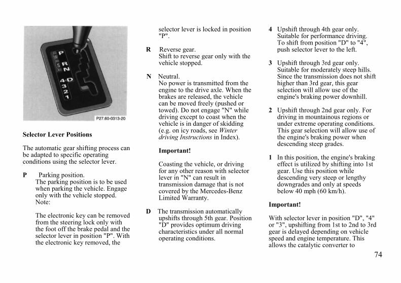
74
Selector Lever Positions
The automatic gear shifting process canbe adapted to specific operatingconditions using the selector lever.
P Parking position.The parking position is to be usedwhen parking the vehicle. Engageonly with the vehicle stopped.Note:
The electronic key can be removedfrom the steering lock only withthe foot off the brake pedal and theselector lever in position "P". Withthe electronic key removed, the
selector lever is locked in position"P".
R Reverse gear.Shift to reverse gear only with thevehicle stopped.
N Neutral.No power is transmitted from theengine to the drive axle. When thebrakes are released, the vehiclecan be moved freely (pushed ortowed). Do not engage "N" whiledriving except to coast when thevehicle is in danger of skidding(e.g. on icy roads, see Winterdriving Instructions in Index).
Important!
Coasting the vehicle, or drivingfor any other reason with selectorlever in "N" can result intransmission damage that is notcovered by the Mercedes-BenzLimited Warranty.
D The transmission automaticallyupshifts through 5th gear. Position"D" provides optimum drivingcharacteristics under all normaloperating conditions.
4 Upshift through 4th gear only.Suitable for performance driving.To shift from position "D" to "4",push selector lever to the left.
3 Upshift through 3rd gear only.Suitable for moderately steep hills.Since the transmission does not shifthigher than 3rd gear, this gearselection will allow use of theengine's braking power downhill.
2 Upshift through 2nd gear only. Fordriving in mountainous regions orunder extreme operating conditions.This gear selection will allow use ofthe engine's braking power whendescending steep grades.
1 In this position, the engine's brakingeffect is utilized by shifting into 1stgear. Use this position whiledescending very steep or lengthydowngrades and only at speedsbelow 40 mph (60 km/h).
Important!
With selector lever in position "D", "4"or "3", upshifting from 1st to 2nd to 3rdgear is delayed depending on vehiclespeed and engine temperature. Thisallows the catalytic converter to

75
heat up more quickly to operatingtemperatures.
During the brief warm-up period thisdelayed upshift and increased enginenoise might be perceived as amalfunction. However, neither theengine nor transmission are negativelyaffected by this mode of operation.
The delayed upshift is effective withvehicle speeds below 31 mph (50km/h) at partial throttle and enginetemperatures below 95°F (35°C).
To avoid overrevving the engine whenthe selector lever is moved to a lowerdriving range, the transmission will notshift to a lower gear as long as thevehicle speed exceeds the speed limitof that gear.
To prevent the engine from laboring atlow RPMs, do not allow the enginespeed to drop too low on uphillgradients.
Depending on the degree of the incline,shift selector lever to a lower gear rangeearly enough to maintain engine RPMwithin the best torque range.
Warning!
On slippery road surfaces, neverdownshift in order to obtain brakingaction. This could result in drivewheel slip and reduced vehiclecontrol. Your vehicle's ABS will notprevent this type of loss of control.
Maneuvering
To maneuver in tight areas, e.g. whenpulling into a parking space, control thevehicle speed by gradually releasing thebrakes. Accelerate gently and neverabruptly step on the accelerator.
To rock a vehicle out of soft ground(mud or snow), alternately shift fromforward to reverse, while applying slightpartial throttle.
Rocking a vehicle free in this mannermay cause the ABS malfunctionindicator lamp to come on. Turn off andrestart the engine to clear themalfunction indication.
Stopping
For brief stops, e.g. at traffic lights,leave the transmission in gear and holdvehicle with the service brake.
For longer stops with the engine idling,shift into "N" or "P" and hold thevehicle with the service brake.
When stopping the vehicle on an uphillgradient, do not hold it with theaccelerator, use the brake. This avoidsunnecessary transmission heat build up.
Warning!
Getting out of your car with theselector lever not fully engaged inposition "P" is dangerous. Also,when parked on an incline, position"P" alone may not prevent yourvehicle from moving, possiblyhitting people or objects.
Always set the parking brake inaddition to shifting to position "P".
When parked on an incline, also turnfront wheel against curb.
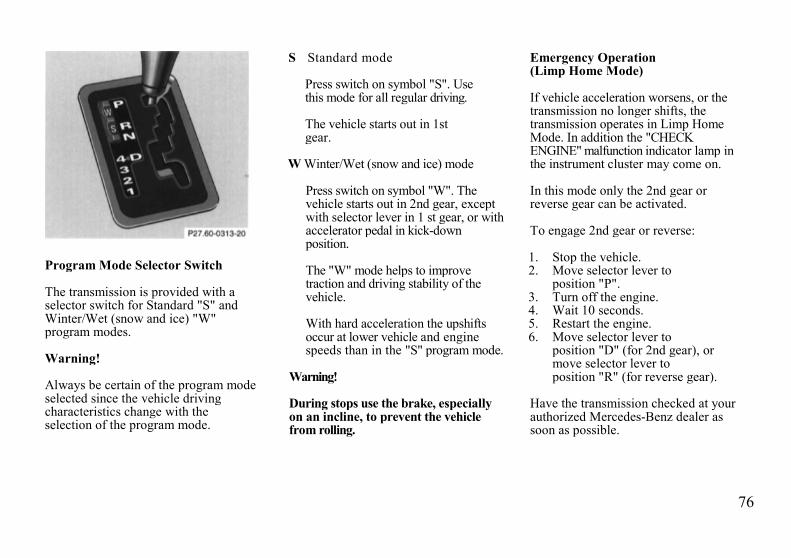
76
Program Mode Selector Switch
The transmission is provided with aselector switch for Standard "S" andWinter/Wet (snow and ice) "W"program modes.
Warning!
Always be certain of the program modeselected since the vehicle drivingcharacteristics change with theselection of the program mode.
S Standard mode
Press switch on symbol "S". Usethis mode for all regular driving.
The vehicle starts out in 1stgear.
W Winter/Wet (snow and ice) mode
Press switch on symbol "W". Thevehicle starts out in 2nd gear, exceptwith selector lever in 1 st gear, or withaccelerator pedal in kick-downposition.
The "W" mode helps to improvetraction and driving stability of thevehicle.
With hard acceleration the upshiftsoccur at lower vehicle and enginespeeds than in the "S" program mode.
Warning!
During stops use the brake, especiallyon an incline, to prevent the vehiclefrom rolling.
Emergency Operation(Limp Home Mode)
If vehicle acceleration worsens, or thetransmission no longer shifts, thetransmission operates in Limp HomeMode. In addition the "CHECKENGINE" malfunction indicator lamp inthe instrument cluster may come on.
In this mode only the 2nd gear orreverse gear can be activated.
To engage 2nd gear or reverse:
1. Stop the vehicle.2. Move selector lever to
position "P".3. Turn off the engine.4. Wait 10 seconds.5. Restart the engine.6. Move selector lever to
position "D" (for 2nd gear), ormove selector lever toposition "R" (for reverse gear).
Have the transmission checked at yourauthorized Mercedes-Benz dealer assoon as possible.

77
Cruise Control
Any given speed above approximately 25mph (40 km/h) can be maintained with thecruise control by operating the lever.
1 Accelerate and set:Lift lever briefly to set speed. Holdlever up to accelerate.
2 Decelerate and set:Depress lever briefly to setspeed.Hold lever down to decelerate
Normally the vehicle is accelerated tothe desired speed with the accelerator.
Speed is set by briefly pushing the leverto position 1 or 2. The accelerator canbe released.
The speed can be increased (e.g. forpassing) by using the accelerator. Afterthe accelerator is released, thepreviously set speed will be resumedautomatically.
If a set speed is to be increased ordecreased slightly, e.g. to adapt to thetraffic flow, hold lever in position 1 or 2until the desired speed is reached, orbriefly tip the lever in the appropriatedirection for increases or decreases in0.6 mph (1 km/h) increments. When thelever is released, the newly set speedremains.
3 Canceling
To cancel the cruise control, brieflypush lever to position 3.
When you step on the brake pedalor the vehicle speed drops belowapprox. 25 mph (40 km/h), forexample when driving upgrade, thecruise control will be canceled.
If the cruise control cancels by itselfand remains inoperative until theengine is restarted, have the systemchecked at your authorizedMercedes-Benz dealer as soon aspossible.
4 ResumeIf the lever is briefly pushed toposition 4 when driving at a speedexceeding approx. 25 mph (40km/h), the vehicle resumes thespeed which was set prior to thecancellation of the cruise control.The last memorized speed iscanceled when the electronic key inthe steering lock is turned toposition 1 or 0.

78
Notes:
If the engine does not brake the vehiclesufficiently while driving on a downgrade,the speed you set on the cruise controlmay be exceeded and you may have tostep on the brake pedal to slow down. Assoon as the grade eases, the cruisecontrolled speed will again be maintainedas long as the brakes were not previouslyapplied, or the lever may be used to re-sume the previously set speed if thebrakes were applied.
Important!
Moving gear selector lever to position"N" switches the cruise control off.
Warning!
Only use the cruise control if thetraffic and weather conditions makeit advisable to travel at a steadyspeed.
• The use of cruise control can bedangerous on winding roads orin heavy traffic becauseconditions do not allow safedriving at a steady speed.
• The use of cruise control can bedangerous on slippery roads.Rapid changes in tire adhesioncan result in wheel spin and lossof control.
The "Resume" function should onlybe operated if the driver is fullyaware of the previously set speed andwishes to resume this particularpreset speed.

79
Multifunction Indicator
Language Selection
Warning message selection is availablein the English, French, German, Italian,or Spanish language.
With the electronic key in steering lockposition 2, simultaneously press resetbuttons for Trip Odometer (O) andMultifunction Indicator (R), located inthe instrument cluster, until the presentlyselected language appears on the screen.
Press button O until the requestedlanguage appears.
Turn the electronic key in steering lockto position 0.
Multiple Malfunctions
When the multiple malfunction symbolappears, this indicates that severalmalfunction messages are stored inmemory.
Push reset button (R) in the instrumentcluster for subsequent messages.
Temporarily Switching Off
To temporarily switch off themultifunction indicator warningsymbol and message, push reset button(R) in the instrument cluster.
The multifunction indicator display isinoperative until the electronic key insteering lock is turned again to position0 or 2.
The symbols and messages for ParkingBrake, Seat Belts, Exterior Lights, andDisplay Defective cannot be switchedoff.
Defective
When the message "Display Defective"appears, this indicates that the systemis not operational, and possibly otherwarnings cannot be shown.
Have the vehicle electronic systemchecked at your authorized Mercedes-Benz dealer as soon as possible.
Charge Indicator
When the symbol and message appearwhile the engine is running, thisindicates a fault which must berepaired at an authorized Mercedes-Benz dealer immediately.
It may indicate that the poly-V-belt hasbroken. Should this condition occur,the poly-V-belt must be replacedbefore continuing to operate thevehicle. Otherwise, the engine willoverheat due to an inoperative waterpump which may result in damage tothe engine.
Do not continue to drive the vehiclewith the charge indicator symboldisplayed. Doing so could result inserious engine damage that is notcovered by the Mercedes-Benz LimitedWarranty.

80
Low Engine Oil Level Warning
When the symbol and message appearwhile the engine is running and atoperating temperature, the engine oillevel has dropped to approximately theminimum mark on the dipstick.
When this occurs, the warning will firstcome on intermittently and then stay onif the oil level drops further.
If no oil leaks are noted, continue todrive to the nearest service stationwhere the engine oil should be toppedto the "full" mark on the dipstick withan approved oil.
The low engine oil level warningshould not be ignored. Extendeddriving with the symbol displayedcould result in serious engine damagethat is not covered by the Mercedes-Benz Limited Warranty.
In addition to the warning symbol, theengine oil level should be periodicallychecked with the dipstick or via themultifunction indicator, for exampleduring a fuel stop, or before a long trip(see Index).
Engine Oil Consumption
Engine oil consumption checks shouldonly be made after the break-in period.During the break-in period, higher oilconsumption may be noticed and isnormal. Frequent driving at high enginespeeds results in increased consumption.
Fuel Reserve Warning
When the symbol and message appearafter starting the engine, or if it comeson while driving, it indicates that thefuel level is down to the reservequantity of approximately: 2.6 gal (10liters).
Tachometer
Red marking on tachometer:Excessive engine speed.
Avoid this engine speed, as it mayresult in serious engine damage that isnot covered by the Mercedes-BenzLimited Warranty.
For engine protection, the fuel supplyis interrupted if the engine is operatedwithin the red marking.

81
Outside Temperature Indicator
The temperature sensor is located in thefront bumper area. Due to its location,the sensor can be affected by road orengine heat during idling or slowdriving. This means that the accuracy ofthe displayed temperature can only beverified by comparison to athermometer placed next to the sensor,not by comparison to external displays(e.g. bank signs etc.).
Adaptation to ambient temperature takesplace in steps and depends on theprevailing driving conditions (stop-and-go or moderate, constant driving) andamount of temperature change.
Warning!
The outside temperature indicator isnot designed to serve as an Ice-Warning Device and is therefore un-suitable for that purpose. Indicatedtemperatures just above the freezingpoint do not guarantee that the roadsurface is free of ice.
Coolant Temperature Gauge
If the antifreeze mixture is effective to-22°F (-30°C), the boiling point of thecoolant in the pressurized coolingsystem of your vehicle is approx.266°F (130°C).
During severe operating conditions andstop-and-go city traffic, the coolanttemperature may rise close to the redmarking.
The engine should not be operated withthe coolant temperature in the red zone.Doing so may cause serious enginedamage which is not covered by theMercedes-Benz Limited Warranty.
Warning!
• Driving when your engine isbadly overheated can causesome fluids which may haveleaked into the enginecompartment to catch fire. Youcould be seriously burned.
• Steam from an overheatedengine can cause serious burnsand can occur just by openingthe engine hood. Stay awayfrom the engine if you see orhear steam coming from it.
Turn off the engine, get out of thevehicle and do not stand near thevehicle until it cools down.
82
Low Engine Coolant LevelWarning
When the symbol and message appearwhile driving, then the coolant levelhas dropped below the required level. Ifno leaks are noticeable and the enginetemperature does not increase, continueto drive to the nearest service stationand have coolant added to the coolantsystem (see Index).
The low engine coolant level warningshould not be ignored. Extendeddriving with the symbol displayed maycause serious engine damage notcovered by the Mercedes-Benz LimitedWarranty.
In cases of major or frequent minorcoolant loss, have the cooling systemchecked at your authorized Mercedes-Benz dealer as soon as possible.
Note:
Do not drive without coolant in thecooling system. The engine willoverheat causing major engine damage.Monitor the coolant temperature gaugewhile driving.
Warning!
Do not spill antifreeze on hot engineparts. Antifreeze contains ethyleneglycol which may burn if it comesinto contact with hot engine parts.You can be seriously burned.
Low Windshield and HeadlampWasher System Fluid Level Warning
When the symbol and message appearwhile the engine is running, the level ofthe reservoir has dropped to approx. 1/3of the total volume. The reservoirshould be refilled with MB WindshieldWasher Concentrate "S" and water (orcommercially available premixedwindshield washer solvent/antifreeze,depending on ambient temperature -see Index) at the next opportunity. Thereservoir for the windshield andheadlamp washer systems is located inthe engine compartment.
83
Exterior Lamp Failure Indicator
When the symbol and message appearafter starting the engine, or if it comes onwhile driving, this symbol indicates afailure in the parking lamp, taillamps,stop lamp, or low beam headlamp.If an exterior lamp fails, the indicatorsymbol will come on only when thatlamp is switched on.
If a brake lamp fails, the lamp failureindicator will come on when applyingthe brake and stays on until the engine isturned off.
Note:
If additional lighting equipment isinstalled (e.g. auxiliary headlamps etc.)be certain to connect into the fuse beforethe failure indicator monitoring unit inorder to avoid damaging the system.
Brake Pad Wear Indicator
When the symbol and message appearduring braking, this indicates that thebrake pads are worn down.
Have the brake system checked at yourauthorized Mercedes-Benz dealer assoon as possible.
Brake Warning
When the brake warning lamp andmessage appear while the engine isrunning, this means:
• there is insufficient brake fluid inthe reservoir (engine runningand parking brake released), or
• the parking brake is set (enginerunning).
Warning!
Driving with the brake warninglamp illuminated can result in anaccident. Have your brake systemchecked immediately if the brakewarning lamp stays on. Don't addbrake fluid before checking thebrake system. Overfilling the brakefluid reservoir can result in spillingbrake fluid on hot engine parts andthe brake fluid catching fire. Youcan be seriously burned.
Note:
If you find that the minimum mark onthe brake fluid reservoir is reached,have the brake system checked forbrake pad thickness and leaks.

84
Antilock Brake System (ABS)
Important!
The ABS improves steering control ofthe vehicle during braking maneuvers.Do not pump the brake pedal, ratheruse firm, steady brake pedal pressure.Pumping the brake pedal defeats thepurpose for ABS and significantlyreduces braking effectiveness.
The ABS prevents the wheels fromlocking up above a vehicle speed ofapproximately 5 mph (8 km/h)independent of road surface conditions.
At the instant one of the wheels isabout to lock up, a slight pulsation canbe felt in the brake pedal, indicatingthat the ABS is in the regulating mode.Keep firm and steady pressure on thebrake pedal while experiencing thepulsation.
On slippery road surfaces, the ABS willrespond even with light brake pedalpressure because of the increasedlikelihood of locking wheels. Thepulsating brake pedal can be anindication of hazardous road conditionsand functions as a reminder to takeextra care while driving.
ABS Control
The ABS malfunction indicator lamp inthe instrument cluster comes on with theelectronic key in steering lock position 2and should go out with the enginerunning.
When the ABS malfunction indicatorlamp symbol and warning in theinstrument cluster come on while theengine is running, it indicates that theABS has detected a malfunction and hasswitched off. In this case, the brakesystem functions in the usual manner,but without antilock assistance.
With the ABS malfunctioning, the BAS,ASR or ESP, if vehicle so equipped, arealso switched off. Both malfunctionindicator lamps come on with the enginerunning.
If the charging voltage falls below 10volts, the malfunction indicator lampcomes on and the ABS is switched off.When the voltage is above this valueagain, the malfunction indicator lampshould go out and the ABS should beoperational.Have the system checked at yourauthorized Mercedes-Benz dealer assoon as possible.
Warning!
ABS cannot prevent the natural lawsof physics from acting on the vehicle,nor can it increase the traction madeavailable by the road conditions. TheABS cannot prevent accidents,including those resulting fromexcessive speed in turns, followinganother vehicle too closely, oraquaplaning. Only a safe, attentive,and skillful driver can preventaccidents. The capabilities of an ABSequipped vehicle must never beexploited in a reckless or dangerousmanner which could jeopardize theuser's safety or the safety of others.
Note:
To alert following vehicles to slipperyroad conditions you discover, operateyour hazard warning flashers asappropriate.
85
Electronic Traction System (ETS)
The ETS improves vehicle traction,especially under slippery roadconditions. It engages at vehicle speedsup to approximately 24 mph (40 km/h),and applies the brakes to the spinningdrive wheel. At approximately 50 mph(80 km/h), the ETS switches off.The ETS warning lamp, located in thespeedometer dial, starts to flash at anyvehicle speed, as soon as the tires losetraction and the wheels begin to spin.
Important!
If the ETS warning lamp flashes:
• during take-off, apply as littlethrottle as possible,
• while driving, ease up on theaccelerator.
Adapt your speed and driving to theprevailing road conditions.
ETS Control
If the yellow ETS malfunctionindicator lamp comes on while the ETSwarning symbol flashes, with theengine running, the electronic tractionsystem is being switched offtemporarily to prevent overheating ofthe drive wheel brakes.
If the ETS malfunction indicator lampcomes on with the engine running, amalfunction has been detected.
Have the ETS checked at yourauthorized Mercedes-Benz dealer assoon as possible.
With the ABS malfunctioning, the ETSis also switched off.
Caution!
If the vehicle is towed with the frontaxle raised (see Towing the vehicle inIndex), or when testing the parkingbrake on a brake test dynamometer, theengine must be shut off. Otherwise, theelectronic traction system willimmediately be engaged and will applythe rear wheel brakes.
Note:
In winter operation, the maximumeffectiveness of the electronic tractionsystem is only achieved withMercedes-Benz recommended M+Sradial-ply tires and/or snow chains.

86
Acceleration Slip Regulation (ASR)
The acceleration slip regulation willengage at all vehicle speeds, if one orboth drive wheels begin to lose tractionand spin due to excessive acceleration.While engaged, the yellow warninglamp in the speedometer flashes.
With the acceleration slip regulationengaged, the brake is applied to thespinning drive wheel until it regainssufficient traction. If both drive wheelslose traction and spin, the brake isapplied to both drive wheels andsimultaneously, engine torque islimited, to improve the vehicle'sdriving stability.
As traction on the road surfaceincreases, the allowable engine torquealso increases again and the brake is nolonger applied to drive wheels.
Important!
If the ASR warning lamp flashes, adaptyour speed and driving to theprevailing road conditions.
Caution!
If the vehicle is towed with the frontaxle raised (see Towing the vehicle inIndex), the engine must be shut off.Otherwise, the acceleration slipregulation will immediately be engagedand will apply the rear wheel brakes.
Notes:
If the ASR malfunction indicator lampcomes on with the engine running, amalfunction has been detected.Pressing the accelerator pedal willrequire greater effort. Only partialengine output is available.
Have the ASR checked at yourauthorized Mercedes-Benz dealer assoon as possible.
With the ABS malfunctioning, theASR is also switched off.
Driving the vehicle with varied sizetires will cause the wheels to rotate atdifferent speeds, therefore theacceleration slip regulation mayactivate (yellow ASR warning lamp ininstrument cluster comes on). For thisreason, all wheels, including the sparewheel, must have the same tire size.
When testing the parking brake on abrake test dynamometer, the enginemust be shut off. Otherwise, theacceleration slip regulation willimmediately be engaged and will applythe rear wheel brakes.
In winter operation, the maximumeffectiveness of the acceleration slipregulation is only achieved withMercedes-Benz recommended M+Sradial-ply tires and/or snow chains.

87
ASR control switch located in centerconsole
ASR Control Switch
ASR control switch located on centerconsole
To improve the vehicle's traction whendriving with snow chains, or startingoff in deep snow, sand or gravel, pressthe upper half of the ASR switch. TheASR warning lamp, located in thespeedometer dial, is continuouslyilluminated.With the ASR system switched off, theengine torque reduction feature iscancelled. Therefore, the enhancedvehicle stability offered by ASR isunavailable.
Adapt your speed and driving to theprevailing road conditions.
A portion of the ASR system remainsactive, even with the switch in the OFFposition.
If one drive wheel loses traction andbegins to spin, the brake is applieduntil the wheel regains sufficienttraction. The traction control engagesat vehicle speeds up to approximately24 mph (40 km/h), and switches off at50 mph (80 km/h).
The ASR warning lamp, located in thespeedometer dial, starts to flash at anyvehicle speed as soon as the tires losetraction and the wheels begin to spin.
To return to the enhanced vehiclestability offered by ASR: press lowerhalf of the switch (the ASR warninglamp in the speedometer dial goes out).
Important!
If the ASR warning lamp flashes:
• during take-off, apply as littlethrottle as possible,
• while driving, ease up on theaccelerator.

88
Electronic Stability Program(ESP) Model E 420 (optional)
The ESP enhances directional controland reduces driving wheel spin of thevehicle under any driving condition.
Over/understeering of the vehicle iscounteracted by applying brakes to theappropriate wheel to create acounterpointing vehicle movement.The ESP warning lamp, located in thespeedometer dial, starts to flash.
Important!
If the ESP warning lamp flashes, adaptyour speed and driving to theprevailing road conditions.
Caution!
If the vehicle is towed with the frontaxle raised (see Towing the vehicle inIndex), the engine must be shut off(electronic key in steering lock position0 or 1). Otherwise, the ESP willimmediately be engaged and will applythe rear wheel brakes.
Notes:
If the ESP malfunction indicator lampcomes on with the engine running, amalfunction has been detected. It ispossible that now only partial engineoutput is available.
Have the ESP checked at yourauthorized Mercedes-Benz dealer assoon as possible.
With the ABS malfunctioning, the ESP isalso switched off.
Driving the vehicle with varied sizetires will cause the wheels to rotate atdifferent speeds, therefore the ESP mayactivate (yellow ESP warning lamp inspeedometer dial comes on). For thisreason, all wheels, including the sparewheel, must have the same tire size.
When testing the parking brake on abrake test dynamometer, the enginemust be shut off. Otherwise, the ESPwill immediately be engaged and willapply the rear wheel brakes.
In winter operation, the maximumeffectiveness of the ESP is onlyachieved with Mercedes-Benzrecommended M+S rated radial-plytires and/or snow chains.

89
ESP control switch located on centerconsole
ESP Control SwitchTo improve the vehicle's traction whendriving with snow chains, or starlingoff in deep snow, sand or gravel, pressthe upper half of the ESP switch. TheESP warning lamp, located in thespeedometer dial, is continuouslyilluminated.
With the ESP system switched off, theengine torque reduction feature iscancelled. Therefore, the enhancedvehicle stability offered by ESP isunavailable.
Adapt your speed and driving to theprevailing road conditions.
A portion of the ESP system remainsactive, even with the switch in the OFFposition.
If one drive wheel loses traction andbegins to spin, the brake is applieduntil the wheel regains sufficienttraction. The traction control engagesat vehicle speeds up to approximately24 mph (40 km/h), and switches off at50 mph (80 km/h).
The ESP warning lamp, located in thespeedometer dial, starts to flash at anyvehicle speed as soon as the tires losetraction and the wheels begin to spin.
To return to the enhanced vehiclestability offered by ESP: press lowerhalf of the switch (the ESP warninglamp in the speedometer dial goes out).
Important!
If the ESP warning lamp flashes:
• during take-off, apply as littlethrottle as possible,
• while driving, ease up on theaccelerator.

90
Emission Control
Certain systems of the engine serve tokeep the toxic components of theexhaust gases within permissible limitsrequired by law.
These systems, of course, will functionproperly only when maintained strictlyaccording to factory specifications.Any adjustments on the engine should,therefore, be carried out only byqualified Mercedes-Benz authorizeddealer technicians. Engine adjustmentsshould not be altered in any way.Moreover, the specified service jobsmust be carried out regularly accordingto Mercedes-Benz servicingrequirements. For details refer to theService Booklet.
Warning!
Inhalation of exhaust gas ishazardous to your health. Allexhaust gas contains carbonmonoxide, and inhaling it can causeunconsciousness and lead to death.
Do not run the engine in confinedareas (such as a garage) which arenot properly ventilated. If you thinkthat exhaust gas fumes are enteringthe vehicle while driving, have thecause determined and correctedimmediately. If you must driveunder these conditions, drive onlywith at least one window fully open.
On-Board Diagnostic System
Vehicles with Diesel engine
When the "CHECK ENGINE" mal-function indicator lamp comes on whilethe engine is running, this indicates amalfunction in the fuel injection system.Only partial engine output is available.Have the system checked at yourauthorized Mercedes-Benz dealer assoon as possible.
Vehicles with gasoline engine
The Sequential Multiport FuelInjection (SFI) control modulemonitors emission control componentsthat either provide input signals to orreceive output signals from the controlmodule. Malfunctions resulting frominterruptions or failure of any of thesecomponents are indicated by the"CHECK ENGINE" malfunctionindicator lamp in the instrument clusterand are simultaneously stored in thediagnostic module.
If the "CHECK ENGINE" malfunctionindicator lamp comes on, have thesystem checked at your authorizedMercedes-Benz dealer as soon aspossible.
An on-board diagnostic connector islocated in the passenger compartmentnear to the parking brake pedal,allowing the accurate identification ofsystem malfunctions through thereadout of diagnostic trouble codes.

91
Winter Driving
Have your vehicle winterized at yourauthorized Mercedes-Benz dealerbefore the onset of winter.
• Change the engine oil if the enginecontains an oil which is notapproved for winter operation. Forviscosity (SAE/CCMC class) andfilling quantity, see Capacities:Fuels, Coolants, Lubricants etc. inIndex.
• Check engine coolant anticorrosion/antifreeze concentration.
• Additive for the windshield washerand headlamp cleaning system: AddMB Concentrate "S" to a premixedwindshield washer solvent/antifreeze which is formulated forbelow freezing temperatures (seeIndex).
• Test battery: Battery capacitydrops with decreasing ambienttemperature. A well chargedbattery helps to ensure that theengine can be started, even at lowambient temperatures.
• Tires: We recommend M+S ratedradial-ply tires on all four wheelsfor the winter season. Observepermissible maximum speed forM+S rated radial-ply tires and thelegal speed limit.
Note:
In winter operation, the maximumeffectiveness of the acceleration slipregulation or of the electronic tractionsystem can only be achieved with M+Sradial-ply tires and/or snow chainsrecommended by Mercedes-Benz.Snow chains maximize performance.
Vehicles with diesel engine –
• For diesel fuels, refer to Index.• Engine block heater:
The engine is equipped with ablock heater. The electrical cablemay be installed free-of-charge atyour authorized Mercedes-Benzdealer by using the coupon in the"Owner's Service and WarrantyPolicy" booklet. The coupon is validfor 12 months from date of vehicledelivery.

92
Snow Chains
Use only snow chains that are testedand recommended by Mercedes-Benz.Your authorized Mercedes-Benz dealerwill be glad to advise you on thissubject.
Chains should only be used on the rearwheels. Follow the manufacturer'smounting instructions.Snow chains should only be driven onsnow covered roads at speeds not toexceed 30 mph (50 km/h). Removechains as soon as possible whendriving on roads without snow.
For tips on driving on slippery winterroads, refer to Index.
Vehicles with Acceleration SlipRegulation (ASR) or ElectronicStability Program (ESP):
When driving with snow chains, pressthe ASR control switch or the ESPcontrol switch, refer to Index.
Vehicles with Sport Package
Use of snow chains in not permissiblewith tire size 235/45 ZR 17.
Traveling Abroad
Abroad, there is a widely-spreadMercedes-Benz service network atyour disposal. If you plan to travel intoareas which are not listed in the indexof your dealer directory, you shouldrequest pertinent information fromyour authorized Mercedes-Benz dealer.

93
Practical Hints

94
Hood
To open:
To unlock the hood, pull release lever(1) under the driver's side of theinstrument panel. At the same timehandle (2) will extend out of theradiator grill (it may be necessary to liftthe hood up slightly).
Caution!
To avoid damage to the windshieldwiper or hood, open the hood only withwiper in the parked position.
Pull handle (2) completely out ofradiator grill and open hood (do notpull upon handle).
To close:
Lower hood and let it drop into lockfrom a height of approx. 1 ft. (30 cm),assisting with hands placed flat onedges of hood (3).
To avoid hood damage, if hood is notfully closed, repeat closing procedure.Do not push down on hood to attempt tofully close it.
Warning!
To help prevent personal injury, stayclear of moving parts when the hoodis open and the engine is running. Besure the hood is properly closedbefore driving. When closing hood,use extreme caution not to catchhands or fingers.
Warning!
Vehicles with gasoline engine:
The engine is equipped with atransistorized ignition system.Because of the high voltage it isdangerous to touch any components(ignition coils, spark plug sockets,ignition cables, diagnostic socket)of the ignition system
• with the engine running,• while starting the engine,• if ignition is "on" and the engine
is turned manually.
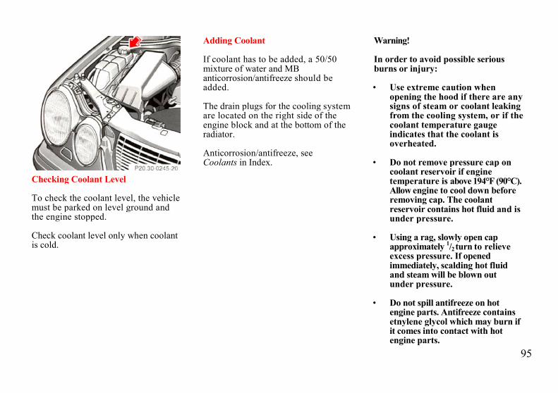
95
Checking Coolant Level
To check the coolant level, the vehiclemust be parked on level ground andthe engine stopped.
Check coolant level only when coolantis cold.
Adding Coolant
If coolant has to be added, a 50/50mixture of water and MBanticorrosion/antifreeze should beadded.
The drain plugs for the cooling systemare located on the right side of theengine block and at the bottom of theradiator.
Anticorrosion/antifreeze, seeCoolants in Index.
Warning!
In order to avoid possible seriousburns or injury:
• Use extreme caution whenopening the hood if there are anysigns of steam or coolant leakingfrom the cooling system, or if thecoolant temperature gaugeindicates that the coolant isoverheated.
• Do not remove pressure cap oncoolant reservoir if enginetemperature is above 194°F (90°C).Allow engine to cool down beforeremoving cap. The coolantreservoir contains hot fluid and isunder pressure.
• Using a rag, slowly open capapproximately 1/2turn to relieveexcess pressure. If openedimmediately, scalding hot fluidand steam will be blown outunder pressure.
• Do not spill antifreeze on hotengine parts. Antifreeze containsetnylene glycol which may burn ifit comes into contact with hotengine parts.

96
Checking Engine Oil Level
1 Oil dipstick2 Oil filler cap
The engine oil level can be checked byeither the oil dipstick or via themultifunction indicator in the instrumentcluster.
To check the engine oil level, parkvehicle on level ground, with engine atnormal operational temperature.
Check engine oil level approximately 5minutes after stopping the engine,allowing for the oil to return to the oilpan.
Oil level must be betweenthe lower (min) and upper(max) mark of the dipstick.
Fill quantity between upper and lowerdipstick marking level is approximately2.1 US qt (2.0 l).
Do not overfill the engine. Excessiveoil must be drained or siphoned. Itcould cause damage to engine andcatalytic converter not covered by theMercedes-Benz Limited Warranty.
For Low engine oil level warning, seeIndex.
Bleeding of Diesel Fuel SystemIf the engine ran out of fuel, the fuelsystem has to be purged of air afterrefilling the tank.
Turn the key in steering lock fully to theright and crank engine (for up to 40seconds maximum). Only release keyafter engine fires evenly.
Automatic Transmission Fluid Level
The transmission has a permanent fillof automatic transmission fluid.Regular automatic transmission fluidlevel checks and changes are notrequired. For this reason the dipstick isomitted.
When noticing fluid loss or gearshifting malfunctions, have yourauthorized Mercedes-Benz dealercheck the transmission fluid level.
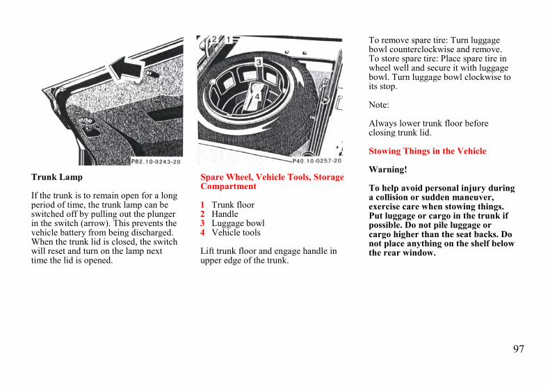
97
Trunk Lamp
If the trunk is to remain open for a longperiod of time, the trunk lamp can beswitched off by pulling out the plungerin the switch (arrow). This prevents thevehicle battery from being discharged.When the trunk lid is closed, the switchwill reset and turn on the lamp nexttime the lid is opened.
Spare Wheel, Vehicle Tools, StorageCompartment
1 Trunk floor2 Handle3 Luggage bowl4 Vehicle tools
Lift trunk floor and engage handle inupper edge of the trunk.
To remove spare tire: Turn luggagebowl counterclockwise and remove.To store spare tire: Place spare tire inwheel well and secure it with luggagebowl. Turn luggage bowl clockwise toits stop.
Note:
Always lower trunk floor beforeclosing trunk lid.
Stowing Things in the Vehicle
Warning!
To help avoid personal injury duringa collision or sudden maneuver,exercise care when stowing things.Put luggage or cargo in the trunk ifpossible. Do not pile luggage orcargo higher than the seat backs. Donot place anything on the shelf belowthe rear window.

98
Vehicle Jack
1 Jack arm2 Jack base
The vehicle jack is stored behind thespare wheel.
See illustration for proper storage of jack.To remove, first remove vehicle tools andspare wheel. Then open clamp andremove vehicle jack.
Before storing the jack in the spare wheelwell, the jack arm must be loweredalmost to the base of the jack.
Warning!
The jack is designed exclusively forjacking up the vehicle at the jacktubes built into either side of thevehicle. To help avoid personalinjury, use the jack only to lift thevehicle during a wheel change. Neverget beneath the vehicle while it issupported by the jack. Keep handsand feet away from the area underthe lifted vehicle. Always firmly setparking brake and block wheelsbefore raising vehicle with jack.
Do not disengage parking brakewhile the vehicle is raised. Be certainthat the jack is always vertical whenin use, especially on hills. Always tryto use the jack on level surface. Besure that the jack arm is fullyinserted in the jack tube. Alwayslower the vehicle onto sufficientcapacity jackstands before workingunder the vehicle.
Wheels
Replace rims or tires with the samedesignation, manufacturer and type asshown on the original part. See yourauthorized Mercedes-Benz dealer forfurther information.
Warning!
Do not mix different tire constructiontypes (i.e. radial, bias, and bias-belted)on your car because handling may beadversely affected and may result inloss of control.
See your authorized Mercedes-Benzdealer for information on tested andrecommended rims and tires forsummer and winter operation. Theycan also offer advice concerning tireservice and purchase.

99
Tire Replacement
Front tires should be replaced in sets.Furthermore - in the event of tirereplacement - the spare wheel (exceptmodel E 420 with Sport Package), ifpossible, should be used on the rearaxle. Rims and tires must be of thecorrect size and type. For dimensions,see "Technical Data".
We recommend that you break in newtires for approx. 60 miles (100 km) atmoderate speed.
It is imperative that the wheel mountingbolts be retightened after approximately60-300 miles (100-500 km) wheneverwheels are fitted, e.g. when the sparewheel is used for the first time or when aset of wheels with M+S tires is installed.
Tightening torque:80 ft.lb. (110 Nm).
For rim and tire specifications, refer to"Technical Data".
Warning!
Worn, old tires can cause accidents.If the tire tread is badly worn, or ifthe tires have sustained damage,replace them.
When replacing rims, use onlygenuine Mercedes-Benz wheel boltsspecified for the particular rimtype. Failure to do so can result inthe bolts loosening and possibly anaccident.
Rotating Wheels
The wheels can be rotated according tothe degree of tire wear while retainingthe same direction of travel.
Rotating, however, should be carriedout at the scheduled service intervals,before the characteristic tire wearpattern (shoulder wear on front wheelsand tread center wear on rear wheels)becomes visible, as otherwise thedriving properties deteriorate.
Important!
Unidirectional tires must always bemounted with arrow on tire sidewallpointing in direction of vehicle forwardmovement.
Notes:
Thoroughly clean the inner side of thewheels any time you rotate the wheelsor wash the vehicle underside.
The use of retread tires is notrecommended. Retread tires mayadversely affect the handlingcharacteristics and safety of the vehicle.
Dented or bent rims can cause tirepressure loss and damage to the tirebeads. For this reason, check rims fordamage at regular intervals. The rimflanges must be checked for wearbefore a tire is mounted. Remove burrs,if any.
Check and ensure proper tire inflationpressure after rotating the wheels. ForTire Inflation Pressure refer to Index.

100
Warning!
The jack is designed exclusively forjacking up the vehicle at the jacktubes built into either side of thevehicle. To help avoid personal injury,use the jack only to lift the vehicleduring a wheel change. Never getbeneath the vehicle while it issupported by the jack. Keep handsand feet away from the area under thelifted vehicle. Always firmly setparking brake and block wheelsbefore raising vehicle with jack.
Do not disengage parking brake whilethe vehicle is raised. Be certain thatthe jack is always vertical when in use,especially on hills. Always try to usethe jack on level surface. Be sure thatthe jack arm is fully inserted in thejack tube. Always lower the vehicleonto sufficient capacity jackstandsbefore working under the vehicle.
Spare Wheel for Sport Package
The spare wheel rim size is 71/2 Jx16 H2 with tire size 215/55 R 16 93 H.
In the case of a flat tire or breakdown,you may temporarily use a 71/2 J x 16 H2 instead of the 8 J x 16 H 2 wheel rimon the rear axle, when observing thefollowing restrictions:
• Do not exceed vehicle speed of50 mph (80 km/h).
• Drive to the nearest repairfacility.
For additional information, refer to"Technical Data".
Changing Wheels
Move vehicle to a level area which is asafe distance from the roadway.
1. Set parking brake and turn onhazard warning flasher.
2. Move selector lever to position"P" and turn off engine.
3. Prevent vehicle from rollingaway by blocking wheels withwheel chocks (not supplied withvehicle) or sizable wood blockor stone. When changing awheel on a hill, place chocks onthe downhill side blocking bothwheels of the other axle. On alevel road, place one chock infront of and one behind thewheel that is diagonally oppositeto the wheel being changed.
4. Using the wrench, loosen but donot yet remove the wheel bolts.
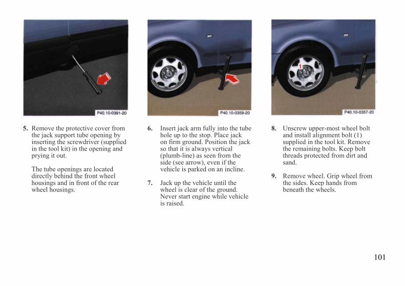
101
5. Remove the protective cover fromthe jack support tube opening byinserting the screwdriver (suppliedin the tool kit) in the opening andprying it out.
The tube openings are locateddirectly behind the front wheelhousings and in front of the rearwheel housings.
6. Insert jack arm fully into the tubehole up to the stop. Place jackon firm ground. Position the jackso that it is always vertical(plumb-line) as seen from theside (see arrow), even if thevehicle is parked on an incline.
7. Jack up the vehicle until thewheel is clear of the ground.Never start engine while vehicleis raised.
8. Unscrew upper-most wheel boltand install alignment bolt (1)supplied in the tool kit. Removethe remaining bolts. Keep boltthreads protected from dirt andsand.
9. Remove wheel. Grip wheel fromthe sides. Keep hands frombeneath the wheels.

102
10. Clean contact surfaces ofwheel and wheel hub. Installspare wheel on wheel hub.Insert wheel bolts and tightenthem slightly.To avoid paint damage, placewheel flat against hub and hold itthere while installing first wheelbolt.Unscrew the alignment bolt (1) toinstall the last wheel bolt.
11. Lower car. Remove jack andinsert jack tube cover.
Before storing the jack, the jack armmust be lowered almost to the base ofthe jack.
Warning!
Always replace wheel bolts that aredamaged or rusted.
Never apply oil or grease to wheelbolts.
Damaged wheel hub threads shouldbe repaired immediately.
Incorrect mounting bolts orimproperly tightened mounting boltscan cause the wheel to come off. Thiscould cause an accident. Be sure touse the correct mounting bolts.
12. Using the wrench, tighten thefive bolts evenly, following thesequence illustrated, until allbolts are tight.
Observe a tightening torque of80 ft.lb. (110 Nm).
13. Ensure proper tire pressure.
Important!
When installing new wheels themounting bolts must be retightenedafter approx. 60 - 300 miles (100 to500 km).

103
Tire Inflation Pressure
A table (see fuel filler flap) lists the tireinflation pressures specified forMercedes-Benz recommended tires aswell as for the varying operatingconditions.
Important!
Tire pressure changes by approx. 1.5psi (0.1 bar) per 18°F (10°C) of airtemperature change. Keep this in mindwhen checking tire pressure inside agarage - especially in the winter.
Example:
If garage temperature = approx. +68°F(+20°C) and ambient temperature =approx. +32°F (0°C) then the adjustedair pressure = specified air pressure +3psi (+0.2 bar).
Tire pressures listed for light loads areminimum values offering high drivingcomfort. Increased inflation pressuresfor heavy loads produce favorablehandling characteristics with lighterloads and are perfectly permissible.
The ride of the vehicle, however, willbecome somewhat harder.
Tire temperature and pressureincrease with the vehicle speed. Tirepressure should therefore only becorrected on cold tires. Correct tirepressure in warm tires only if pressurehas dropped below the pressure listedin the table and the respectiveoperating conditions are taken intoconsideration.
An underinflated tire due to a slowleak (e.g. due to a nail in the tire) maycause damage such as treadseparation, bulging etc.. Regular tirepressure checks (including the sparetire) at intervals of no more than 14days are therefore essential.
If a tire constantly loses air, it shouldbe inspected for damage.
Warning!
Do not overinflate tires.Overinflating tires can result insudden deflation (blowout) becausethey are more likely to becomepunctured or damaged by roaddebris, potholes etc.. Follow recom-mended inflation pressures.
Do not overload the tires byexceeding the specified vehiclecapacity weight (as indicated by thelabel on the driver's door latch post).Overloading the tires can overheatthem, possibly causing a blowout.

104
Exterior Lamps
Headlamp Adjustment
Correct headlamp adjustment isextremely important. Check andreadjust headlamps at regular intervalsand when a bulb has been replaced.
Headlamp Assembly
1 Headlamp horizontal adjustmentscrew
2 Headlamp vertical adjustmentscrew
3 Clamps for headlamp cover4 Bulb socket for turn signal lamp5 Electrical connector for low
beam headlamp bulb6 Electrical connector for high
beam headlamp bulbXenon lamp (optional) ignitionmodule for low beam
7 Bulb socket for parking andstanding lamp
8 Level for headlamp verticaladjustment

105
Replacing Bulb:
When replacing bulbs, install only 12volt bulbs with the specified wattrating.
When replacing halogen bulbs do nottouch glass portion of bulb with barehands. Use plain paper or a clean cloth.
Warning!
Halogen lamps contain pressurizedgas. A bulb can explode if you:
• touch or move it when hot,• drop the bulb,• scratch the bulb.
Wear eye and hand protection.
Bulbs for Low or High BeamH7 (55 W)
Open hood.
Move retaining clamps (3) aside andremove cover. Pull off electricalconnector (5) or (6). Unhook clampingring and pull out bulb together withclamping ring. Remove bulb.
Insert new bulb (seating properly incutouts of bulb socket), mount clampingring. Reinstall and push electricalconnector on securely. Reinstall coverand fasten with retaining clamps (3).
Xenon (optional)Bulb for Low Beam
Warning!
Because of high voltage in Xenonlamps, it is dangerous to replace thebulb or repair the lamp and itscomponents. We recommend thatyou have such work done by aqualified technician.
Turn Signal Lamp1156 NA (26.9/5 W/32/4 cp bulb)
Open hood.Twist bulb socket (4) counterclockwiseand pull out. Push bulb into socket,turn counterclockwise and remove.Insert new bulb in socket, push in andtwist clockwise. Reinstall bulb socket.Reinstall lamp assembly until properlyseated.
Parking and Standing LampH 6W (6 W bulb)
Open hood.
Rotate cover (3) counterclockwise andremove.
Twist bulb socket (7) counterclockwiseand pull out. Push bulb into socket,turn counterclockwise and remove.
Insert new bulb in socket, push in andtwist clockwise. Reinstall bulb socket.Reinstall lamp assembly until properlyseated.

106
Adjusting Headlamp
Correct headlamp adjustment isextremely important. To check andreadjust a headlamp, follow steps 1through 7. Please note:
• Low beam adjustmentssimultaneously aim the high beam.
• Vehicle should have a normal trunkload.
• Vertical aim adjustments changehorizontal aim.
1. Park vehicle on level surface approx.6 inches (152 mm) from a verticaltest screen or wall. The centerline ofthe vehicle must be at a 90° angle tothe test screen.
2. Using a "T" square and a carpenter'slevel, align and mark a verticalcenterline (8) on the test screen usingthe outer reference point (low beam)as found on each headlamp lens.As a check, the distance betweencenterlines should be 491/4 inches(1250 mm).
3. Move vehicle on the levelsurface 25 feet (7.6 m) straightback from the wall.
4. Open hood.5. Vertical headlamp aim
(low beams on):Turn adjusting screw (2) (coun-terclockwise to adjust headlampdownward, clockwise upward) untilbubble in the level (8) is centeredon the "O" mark.Graduations: 0.18° pitch.

107
6. Horizontal headlamp aim(low beams on):Turn adjusting screw (1)(counterclockwise to adjust tothe left, clockwise to the right)until the headlamps (low beam)illuminate the test screen asshown. The vertex of the angleformed in each beam imageshould align with the verticalcenterline (11) of each lamp.
The left and right headlamps must beadjusted individually
7. The "O" on the indicator wheel(9) should align with projection(10). If it does not, with a smallscrewdriver, pry indicator wheelup and rotate so that the "O"aligns with projection (1). Pushdown indicator wheel until itsnaps in place.
Graduations: 0.38° pitch.

108
Taillamp Assemblies
Open trunk lid.
1 Turn signal lamp(21 W/32 cp bulb)
2 Stop, tail and parking lamp(21/4 W/35/1.2 cp bulb)
3 Tail, parking and side marker lamp(5 W/4 cp bulb)
Swing cover aside. Twist bulb socketcounterclockwise and pull out. Pushbulb into socket, turn counterclockwiseand remove.Insert new bulb in socket, push in andtwist clockweise. Reinstall bulb socket,and close cover
4 Driver's side:Rear fog lamp(21 W/32 cp bulb)
5 Backup lamp(21 W/32 cp bulb)
Twist bulb socket counterclockwise andpull out. Push bulb into socket, turncounterclockwise and remove.
Insert new bulb in socket, push in andtwist clockwise. Reinstall bulb socket.
License Plate Lamps(5 W/4 cp bulb)
Loosen three securing screws (1),remove trunk handle with lamps andtake out bulb.
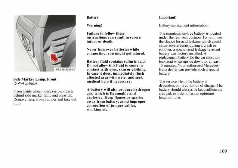
109
Side Marker Lamp, Front(5 W/4 cp bulb)
From inside wheel house (arrow) reachbehind side marker lamp and press tab.Remove lamp from bumper and take outbulb.
Battery
Warning!
Failure to follow theseinstructions can result in severeinjury or death.
Never lean over batteries whileconnecting, you might get injured.
Battery fluid contains sulfuric acid.Do not allow this fluid to come incontact with eyes, skin or clothing.In case it does, immediately flushaffected area with water and seekmedical help if necessary.
A battery will also produce hydrogengas, which is flammable andexplosive. Keep flames or sparksaway from battery, avoid improperconnection of jumper cables,smoking etc..
Important!
Battery replacement information:
The maintenance-free battery is locatedunder the rear seat cushion. To minimizethe chance for acid leakage which couldcause severe burns during a crash orrollover, a special acid leakage resistantbattery was factory installed. Areplacement battery for the car must notleak acid when upside down for at least15 minutes. Your authorized Mercedes-Benz dealer can provide such a specialbattery.
The service life of the battery isdependent on its condition of charge. Thebattery should always be kept sufficientlycharged, in order to last an optimumlength of time.

110
Therefore, we strongly recommendthat you have the battery chargechecked frequently, and corrected ifnecessary, especially if you use thevehicle less than approximately 200miles (300 km) per month, mostly forshort distance trips, or if it is not usedfor long periods of time.
Only charge a battery with a batterycharger after the battery has beendisconnected from the vehicle electricalcircuit.
Always disconnect the battery negativelead first and connect last.
When removing and connecting thebattery, always make sure that allelectrical consumers are off and the key isin steering lock position 0. The battery, itsfiller caps, the vent tube and the oppositeplug must always be securely installedwhen the car is in operation. Duringremoval and installation always protectthe disconnected battery positive (+)terminal with the cover attached to thebattery.
While the engine is running the batteryterminal clamps must not be loosenedor detached, otherwise the generatorand other electronic components wouldbe damaged.
Notes:
After reconnecting the battery alsoresynchronize the front seats, front seathead restraints, the Express feature ofthe power windows, and the ElectronicStability Program (ESP) (see Powerseats, front, Head restraints, Powerwindows, and Electronic stabilityprogram in Index).
Battery Recycling
Batteries contain materials that canharm the environment with improperdisposal.
Large 12 Volt storage batteries containlead.
Recycling of batteries is thepreferred method of disposal.
Many states require sellers of batteriesto accept old batteries for recycling.

111
Fuses
Before replacing a blown fuse,determine the cause of the short circuit.
Spare fuses are supplied inside themain fuse box. Observe amperage andcolor of fuse.
A special fuse puller is supplied withthe vehicle tools.
Always use a new fuse for replacement.Never attempt to repair or bridge ablown fuse.
1 Main fuse box in enginecompartment
To gain access to the main fusebox (1), release clamp (arrow),lift the fuse box cover up andremove it.
To close the main fuse box,engage right end of cover andsecure with clamp.
2 Auxiliary fuse box below rearseat bench
To gain access, remove rear seatbench. See Index.
3 Auxiliary fuse box to left ofExterior lamp switch
To gain access, open door, pry offcover and remove.

112
Jump Starting
Warning!
Failure to follow these directions willcause damage to the electroniccomponents, and can lead to abattery explosion and severe injuryor death.
Never lean over batteries whileconnecting or jump starting, youmight get injured.
Battery fluid contains sulfuric acid.Do not allow this fluid to come incontact with eyes, skin or clothing. Incase it does, immediately flushaffected area with water, and seekmedical help if necessary.
A battery will also produce hydrogengas, which is flammable and veryexplosive. Keep flames or sparksaway from battery, avoid improperconnection of jumper cables,smoking etc..
Read all instructions beforeproceeding.
If the battery is discharged, the engineshould be started with jumper cables andthe (12 V) battery of another vehicle.
Jump start the car by using the batteryterminals located under hood.
Proceed as follows:
1. Position the vehicle with thecharged battery so that thejumper cables will reach, butnever let the vehicles touch.Make sure the jumper cables donot have loose or missinginsulation.
2. On both vehicles:
• Turn off engine and all lightsand accessories, excepthazard warning flashers orwork lights.
• Apply parking brake and shiftselector lever to position "P".
Important!
3. Clamp one end of the first jumpercable to the positive (+) terminal ofthe discharged battery and theother end to the positive (+)terminal of the charged battery.Make sure the cable clamps do nottouch any other metal parts.
4. Clamp one end of the secondjumper cable to the groundednegative (-) terminal of the chargedbattery and the final connection tothe negative (-) terminal of thedischarged battery.

113
Important!
5. Start engine of the vehicle withthe charged battery and run athigh idle. Make sure the cablesare not on or near pulleys, fans,or other parts that move whenthe engine is started. Allow thedischarged battery to charge afew minutes. Start engine of thedisabled vehicle in the usualmanner.
6. After the engine has started, removejumper cables by exactly reversingthe above installation sequence,starting with the last connectionmade first. When removing eachclamp, make sure that it does nottouch any other metal while theother end is still attached.
Important!
A discharged battery can freeze atapprox. +14°F (-10°C). In that case, itmust be thawed out before jumpercables are used. A frozen battery canexplode and cause personal injury.Jumper cable specifications:
• Minimum cable cross-section of25 mm2 or approx. 2 AWG
• Maximum length of 11.5ft. (3.5 m).
Towing the Vehicle
The rear towing eye is located at theright, below the bumper. The fronttowing eye is located on the passengerside behind a flap in the bumper panel.
Flap removal:
Insert finger in recess of flap and pullflap out.
Flap installation:
Engage flap at bottom and press in topsecurely.
We recommend that the vehicle betransported using flat bed equipment.This method is preferable to other typesof towing.
The vehicle may be towed with allwheels on the ground and the selectorlever in position "N" for distances up to30 miles (50 km) and at a speed not toexceed 30 mph (50 km/h). Theelectronic key must be in steering lockposition 2.
To positively avoid a possibility ofdamage to the transmission, however,we recommend to disconnect the driveshaft at the rear axle drive flange onany towing beyond a short tow to anearby garage.
Do not tow with sling-type equipment.Towing with sling-type equipment overbumpy roads will damage radiator andsupports.
Use wheel lift, dolly, or flat bedequipment, with electronic key insteering lock turned to position 0.

114
Warning!
With the engine not running, there isno power assistance for the brakingand steering systems. In this case, itis important to keep in mind that aconsiderably higher degree of effortis necessary to brake and steer thevehicle.
Note:
To signal turns while being towed withhazard warning flasher in use, turnelectronic key in steering lock toposition 2 and activate combinationswitch for left or right turn signal inusual manner - only the selected turnsignal will operate.
Upon canceling the turn signal, thehazard warning flasher will operateagain.
Caution!
Vehicles with Acceleration SlipRegulation (ASR)
If the vehicle is towed with the frontaxle raised, the engine must be shut off(electronic key in steering lock position0 or 1). Otherwise, the ASR willimmediately be engaged and will applythe rear wheel brakes.
Caution!
Vehicles with Electronic TractionSystem (ETS)
If the vehicle is towed with one axleraised, the engine must be shut off(key in steering lock position 0 or 1).Otherwise, the ETS will immediately beengaged and will apply the brakes

115
Cleaning and Care of the Vehicle
Warning!
Many cleaning products can behazardous. Some are poisonous,others are flammable. Always followthe instructions on the particularcontainer. Always open your car'sdoors or windows when cleaning theinside.
Never use fluids or solvents that arenot designed for cleaning your car.
In operation, your vehicle is subjectedto varying external influences which, ifgone unchecked, can attack the paint-work as well as the underbody andcause lasting damage.
Such damage is caused not only byextreme and varying climaticconditions, but also by air pollution,road salt, tar, gravel and stonechipping. Grease and oil, fuel, coolant,brake fluid, bird droppings, insects, treeresins etc. should be removedimmediately to avoid paint damage.
Frequent washing reduces and/oreliminates the aggressiveness andpotency of the above adverse influences.
More frequent washings are necessaryto deal with unfavorable conditions; forexample, near the ocean, in industrialareas (smoke, exhaust emissions), orduring winter operation.
You should check your vehicle fromtime to time for stone chipping or otherdamage. Any damage should berepaired as soon as possible to preventthe start of corrosion.
In doing so, do not neglect theunderside of the vehicle. A prerequisitefor a thorough check is a washing ofthe underbody followed by a thoroughinspection. Damaged areas need to bere-undercoated.
Your vehicle has been treated at thefactory with a wax-base rust-proofingin the body cavities which will last forthe lifetime of the vehicle. Post-production treatment is neithernecessary nor recommended by
Mercedes-Benz because of thepossibility of incompatibility betweenmaterials used in the productionprocess and others applied later.
We have selected car-care products andcompiled recommendations which arespecially matched to our vehicles andwhich always reflect the latesttechnology. You can obtain Mercedes-Benz approved car-care products atyour authorized Mercedes-Benz dealer.
Scratches, corrosive deposits, corrosionor damage due to negligent or incorrectcare cannot always be removed orrepaired with the car-care productsrecommended here. In such cases it isbest to seek aid at your authorizedMercedes-Benz dealer.
The following topics deal with thecleaning and care of your vehicleand give important "how-to"information as well as references toMercedes-Benz approved car-careproducts.
Additional information can be found inthe booklet titled "Car Care".

116
Engine Cleaning
Prior to cleaning the enginecompartment make sure to protectelectrical components and connectorsfrom the intrusion of water and cleaningagents.
Corrosion protection, such as MBAnticorrosion Wax should be applied tothe engine compartment after everyengine cleaning. Before applying, allcontrol linkage bushings and jointsshould be lubricated. The poly-V-beltand all pulleys should be protected fromany wax.
Car Washing
Do not use hot water or wash your carin direct sunlight. Use only a mild carwash detergent, such as Mercedes-Benz approved Car Shampoo.
Thoroughly spray the car with adiffused jet of water. Direct only a veryweak spray towards the.
ventilation intake. Use plenty of waterand rinse the sponge and chamoisfrequently.
Rinse with clear water and thoroughlywipe dry with a chamois. Do not allowcleaning agents to dry on the finish.
If the vehicle has been run through anautomatic car wash - in particular oneof the older installations -rewipe therecessed sections in the taillamps(designed to prevent soiling) ifnecessary. No solvents (fuels, thinnersetc.) must be used.
In the winter, thoroughly remove alltraces of road salt as soon as possible.
When washing the underbody, do notforget to clean the inner sides of thewheels.
Tar Stains
Quickly remove tar stains before theydry and become more difficult toremove. A tar remover is recommended.
Window Cleaning
Use a window cleaning solution on allglass surfaces. An automotive glasscleaner is recommended.
Headlamps, Taillamps,Turn Signal Lenses
Use a mild car wash detergent, such asMercedes-Benz approved CarShampoo, with plenty of water.
To prevent scratches, never applystrong force or use a hard cloth whencleaning the lenses. Do not attempt towipe dirty lenses with a dry cloth orsponge.
Plastic and Rubber Parts
Do not use oil or wax on these parts.
Wiper Blade
Clean the wiper blade rubber with aclean cloth and detergent solution.Replace blade twice a year; oncebefore and once after winter.

117
Seat Belts
The webbing must not be treated withchemical cleaning agents. Use onlyclear, lukewarm water and soap. Do notdry the webbing at temperatures above176°F (80°C) or in direct sunlight.
Warning!
Do not bleach or dye seat belts as thismay severely weaken them. In acrash they may not be able toprovide adequate protection.
Hard Plastic Trim Items
Pour Mercedes-Benz approved InteriorCare onto soft lint-free cloth and applywith light pressure.
Headliner andShelf below Rear Window
Clean with soft bristle brush, or use adry-shampoo cleaner in case ofexcessive dirt.
Instrument Cluster
Use a gentle dishwashing detergent ormild detergent for delicate fabrics as awashing solution. Wipe with a clothmoistened in lukewarm solution. Donot use scouring agents.
Steering Wheel and GearSelector Lever
Wipe with a damp cloth and drythoroughly or clean with Mercedes-Benz approved Leather Care.
Upholstery
Using aftermarket seat covers orwearing clothing that have thetendency to give off coloring (e.g.when wet etc.) may cause theupholstery to become permanentlydiscolored. By lining the seats with aproper intermediate cover, contact-discoloration will be prevented.
Leather Upholstery Wipe leatherupholstery with a damp cloth and drythoroughly or clean with Mercedes-Benz approved Leather Care. Exerciseparticular care when cleaningperforated leather as its undersideshould not become wet.
MB Tex Upholstery Pour Mercedes-Benz approved Interior Care onto softlint-free cloth and apply with lightpressure.

118
Paintwork, Painted BodyComponents
Mercedes-Benz approved Paint Careshould be applied when water drops onthe paint surface do not "bead up";normally in 3 to 5 months, dependingon climate and washing detergent used.
Mercedes-Benz approved Paint Cleanershould be applied if paint surfaceshows signs of dirt embedding (i.e. lossof gloss).
Do not apply any of these products orwax if your car is parked in the sun orif the hood is still hot.
Use the appropriate MB-Touch-Up Stickfor quick and provisional repairs ofminor paint damage (i.e. chips fromstones, car doors etc.).
Light Alloy Wheels
Mercedes-Benz approved Wheel Careshould be used for regular cleaning ofthe light alloy wheels.
If possible, clean wheels once a weekwith Mercedes-Benz approved WheelCare, using a soft bristle brush and astrong spray of water.
Follow instructions on container.
Note:
Use only acid-free cleaning materials.The acid could lead to corrosion.
Ornamental Moldings
For regular cleaning and care of verydirty chrome-plated parts, use a chromecleaner.
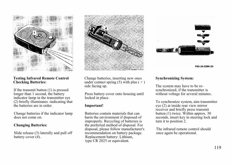
119
Testing Infrared Remote ControlChecking Batteries:
If the transmit button (1) is pressedlonger than 1 second, the batteryindicator lamp in the transmitter eye(2) briefly illuminates -indicating thatthe batteries are in order.
Change batteries if the indicator lampdoes not come on.
Changing Batteries:
Slide release (3) laterally and pull offbattery cover (4).
Change batteries, inserting new onesunder contact spring (5) with plus ( + )side facing up.
Press battery cover onto housing untillocked in place.
Important!
Batteries contain materials that canharm the environment if disposed ofimproperly. Recycling of batteries isthe preferred method of disposal. Fordisposal, please follow manufacturer'srecommendation on battery package.Replacement battery: Lithium,type CR 2025 or equivalent.
Synchronizing System:
The system may have to be re-synchronized, if the transmitter iswithout voltage for several minutes.
To synchronize system, aim transmittereye (2) at inside rear view mirrorreceiver and briefly press transmitbutton (1) twice. Within approx. 30seconds, insert key in steering lock andturn it to position 2.
The infrared remote control shouldonce again be operational.

120
Front Head Restraints
Warning!
For your protection, drive only withproperly positioned head restraints.
Adjust head restraint to support theback of the head approximately atear level.
Do not drive the vehicle without theseat head restraints. Head restraintsare intended to help reduce injuriesduring an accident.
Front seat head restraint, removal
Removal:
Push button (1) up to bring the poweradjustable head restraint to its highestposition.
Pull out head restraint completely withboth hands.
Installation:
Push button (1) of the power adjustablehead restraint up for approximately 5seconds.
Insert the head restraint and push itdown to the stop.
Adjust head restraint to the desiredposition.
For positioning of head restraints referto sections Power Seats, and HeadRestraints, Rear in Index.

121
Rear Seat Cushion
Removal: Pull locking tabs up (on leftand right side of seat) and lift seat at thefront.Installation: Guide seat belt bucklesthrough openings in seat cushion. Sliderear edge of cushion under the backrestas far as it will go, and push front ofcushion down until it locks in place.
Caution!Watch out for sharp edges whenremoving or installing the rear seatcushion, and make sure that it issecurely locked in place again, to preventpersonal injury.
Emergency Operation ofSliding/Pop-Up Roof
The sliding/pop-up roof can be openedor closed manually should an electricalmalfunction occur.
The sliding/pop-up roof drive is locatedbehind the lens of the left interior lampbetween the sun visors.
1. Pry off lens (1) by using a screwdriver.
2. Obtain crank (2) (supplied withvehicle) and insert it throughhole.
To slide the roof closed or to raise theroof at the rear: turn crank clockwise.
To slide the roof open or to lower theroof at the rear: turn crankcounterclockwise.

122
Replacing Wiper Blade Insert
For safety reasons, remove electronickey from steering lock before replacingthe wiper blade, otherwise the motorcan suddenly turn on and cause injury.
Notes:
Do not open engine hood with wiperarm folded forward.
Do not allow the wiper arm to contactthe windshield glass without a wiperblade inserted. The glass may bescratched or broken.
Make certain that the wiper blade isproperly installed. An improperlyinstalled wiper blade may causewindshield damage.
Removal:
Fold wiper arm forward. Press safetytab down (1), push wiper bladedownward (2) and remove.
Place wiper blade on firm support.Slide (direction of arrow) the wiperblade insert out of the retainer claws.
Installation:
Slide (direction of arrow) wiper bladeinsert into retainer claws until tabs areengaged.
Insert wiper blade between tabs (3) onthe wiper arm, and slide into end ofwiper arm. Press safety tab upwarduntil it locks in place.

123
Manual Release of Fuel Filler Flap
The manual release knob is locatedbehind the right side trunk panel.
In case the central locking system doesnot release the fuel filler flap, pull themanual release knob whilesimultaneously opening the fuel fillerflap.
Roof Rack
Use only those roof racks approved byMercedes-Benz to avoid damage to thevehicle. Follow manufacturer'sinstallation instructions.
Mount supports only between markingson border of roof which are visible whendoors are opened.
Spare Parts Service
All authorized Mercedes-Benz dealersmaintain a stock of original spare partsrequired for maintenance and repairwork. In addition, strategically locatedparts distribution centers provide quickand reliable parts service.
More than 300,000 different spareparts, for other Mercedes-Benz models,are available.
Mercedes-Benz original spare parts aresubjected to the most stringent qualityinspections. Each part has beenspecifically developed, manufacturedor selected for and adapted toMercedes-Benz vehicles.
Therefore, Mercedes-Benz originalspare parts should be installed.

124
E 300 DIESEL
Layout of Poly-V-belt Drive
1 Automatic belt tensioner2 Crankshaft3 Air conditioning compressor
E 320
4 Fan5 Idler pulley6 Generator (alternator)7 Idler pulley8 Power steering pump
E420
9 Model E 300 DIESEL: Coolantpump, fan Models E 320, E 420:Coolant pump
For dimensions of the poly-V-belt, seeTechnical Data in Index.

125
Technical Data

126
Identification Labels
When ordering spare parts, pleasespecify vehicle identification and enginenumbers.
1 Certification Label2 Vehicle Identification No. (VIN)3 VIN, visible (lower edge of
windshield)4 Engine No.
E 300 Diesel,E 320(E 420 only: front right)
5 Body No. and Paintwork No.6 Emission Control Label7 Information Label
California versionVacuum line routing foremission control system

127
Vehicle Data Card
The vehicle data card contains allimportant data pertaining to the vehicle.It should be kept in the service bookletwhere indicated, and it is needed whenobtaining replacement or additionalkeys at your authorized Mercedes-Benz dealer.
Warranty Coverage
Your vehicle is covered under theterms of the "warranties" printed in theOwner's Service and WarrantyInformation Booklet and yourauthorized Mercedes-Benz dealer willexchange or repair any defective partsin accordance with the terms of thefollowing warranties:
1. New vehicle limited warranty2. Emission systems warranty3. Emission performance warranty4. California and Massachusetts
emission control systemswarranty.
Loss of Owner's Service andWarranty Information Booklet
Should you lose your Owner's Serviceand Warranty Information Booklet,have your authorized Mercedes-Benzdealer arrange for a replacement. Itwill be mailed to you.

128
Technical Data Rims – TiresModel E 300 DIESEL (210 020)1 Rims
(light alloy rims) 7 1/² J x 16 H 2Wheel offset 41 mm (1.6 in)
Engine 606 All season tires:Mode of operation Diesel 4-stroke Radial-ply tires 215/55 R 16 93 H
Winter tires:No. of cylinders 6 Radial-ply tires 215/55 R 16 93 H M+SBore 87.00 mm (3.43 in)Stroke 84.00 mm (3.31 in) Electrical SystemTotal piston displacement 2996 m³ (182.8 cu.in)Compression ratio 22 Generator (alternator) 14 V/90 AOutput acc.to SAE J 1349 100 kW/5000rpm Starter motor 12 V/2.2 kW
(134 hp/5000 rpm) Battery 12 V/100 AhMaximum torque acc. to SAE J 1349 210 Nm/2600 rpm
(155 ft-lb/2600 rpm)Maximum engine speed 5450 rpmFiring order 1-5-3-6-2-4Poly – V belts length 2140 mm
1 The quoted data apply only to the standard vehicle. Seean authorized Mercedes-Benz dealer for the correspondingdata of all special bodies and special equipment.

129
Technical DataMain Dimensions
Weights See certification tagRoof load max. 100 kg (220 lb) Overall vehicle length 4810 mm (189.4 in)Trunk load max. 100 kg ( 220 lb) Overall vehicle width 1799 mm ( 70.8 in)
Overall height: 1439 mm ( 56.7 in)Wheel base 2833 mm (111.5 in)Track, front 1529 mm ( 60.2 in)Track, rear 1521 mm ( 59.9 in)

130
Technical Data E 300 Diesel Rims – TiresModel E 320 (210 055)1 Rims
(light alloy rims) 7 1/² J x 16 H 2Wheel offset 41 mm (1.6 in)
Engine 104 All season tires:Mode of operation 4-stroke engine, Radial-ply tires 215/55 R 16 99 H
gasoline injection Winter tires:No. of cylinders 6 Radial-ply tires 215/55 R 16 93 H M+SBore 89.90 mm (3.54 in)Stroke 84.00 mm (3.30 in) Electrical SystemTotal piston displacement 3199 m³ (195.2 cu.in)Compression ratio 10 Generator (alternator) 14 V/90 AOutput acc.to SAE J 1349 162 kW/5500rpm Starter motor 12 V/1.7 kW
(217 hp/5500 rpm) Battery 12 V/100 AhMaximum torque acc. to SAE J 1349 315 Nm/3850 rpm Spark plugs Bosch F 8 DPER
(232 ft-lb/3850 rpm) Beru 14 F-8 DPERMaximum engine speed 6400 rpm Electrode gap 1.0 mm (0.039 in)Firing order 1-5-3-6-2-4 Tightening torque 15-22 ft.lb. (20-30 Nm)Poly – V belts length 2445 mm
1 The quoted data apply only to the standard vehicle. Seean authorized Mercedes-Benz dealer for the correspondingdata of all special bodies and special equipment.

131
Technical Data E 320Main Dimensions
Weights See certification tagRoof load max. 100 kg (220 lb) Overall vehicle length 4810 mm (189.4 in)Trunk load max. 100 kg ( 220 lb) Overall vehicle width 1799 mm ( 70.8 in)
Overall height: 1439 mm ( 56.7 in)Wheel base 2833 mm (111.5 in)Track, front 1529 mm ( 60.2 in)Track, rear 1521 mm ( 59.9 in)

132

133

134
Fuels, Coolants, Lubricants etc. – Capacities
Vehicle components and their respective lubricants must match. Therefore use only brands tested and recommended by us.Please refer to the Factory Approved Service Products pamphlet, or inquire at your authorized Mercedes-Benz dealer.
Model Capacity Fuels, coolants, lubricants etc.
E 300 Diesel 7.4 US qt (7.0 1) Recommended engine oilsEngine with oil filter E 320
E 300 Diesel 7.5 US qt (7.1 1)Automatic transmission E 320 7.7 US qt (7.3 1) Automatic transmission fluid
E 300 Diesel 1.2 US qt (1.1 1)Rear axle E 320 1.4 US qt (1.3 1) Hypoid gear oil SAE 90, 85 W 90
Power steering approx. 1.1 US qt (1.0 I) MB Power steering fluid
Front wheel hubs approx. 2.1 oz (60g) each High temperature roller bearing grease

135
Model Capacity Fuels, coolants, lubricants etc.
Accelerator controllinkage
Hydraulic fluid
Brake system approx. 0.5 US qt (0.5 1) MB Brake fluid (DOT 4)
Windshield washersystem
approx. 5.8 US qt (5.5 1) MB Windshield washer concentrate "S"1
Headlamp washer system approx. 1 .9 US qt (1 .8 I) MB Windshield washer concentrate "S"1
E 300 Diesel approx. 1 0.0 US qt (9.5 I) MB Anticorrosion/antifreeze
Cooling system E 320E 300 Diesel approx. 21.1 US gal (80.0 I)
approx. 2.6 US gal (10.01)Diesel fuels ace. to ASTM D 975 grades 1-Dand 2-D
E 320 approx. 21.1 US gal (80.0 I) Premium unleaded gasoline: PostedFuel tank including areserve ofAir conditioner system R-134a refrigerant and special lubricant (Never
R-12)1 Use MB Windshield Washer Concentrate "S" and water for temperatures above freezing or MB
Windshield Washer Concentrate "S" and commercially available premixed windshield washersolvent/antifreeze for temperatures below freezing. Follow suggested mixing ratios, seeWindshield!Headlamp Washer System in Index.

136
Engine Oils
Engine oils are specifically tested fortheir suitability in our engines.Therefore, use only engine oilsrecommended by Mercedes-Benz.Information on recommended brands isavailable at your authorized Mercedes-Benz dealer.
Please follow Service Bookletrecommendations for scheduled oilchanges. Failure to do so could result inengine damage not covered by theMercedes-Benz Limited Warranty.
Engine Oil Additives
Do not blend oil additives with engineoil. They may be harmful to the engineoperation.
Damage or malfunctions resulting fromblending oil additives are not coveredby the Mercedes-Benz LimitedWarranty.
Air Conditioner Refrigerant
R-134a (HFC) refrigerant and specialPAG lubricating oil is used in the airconditioner system.
Never use R-12 (CFC) or mineral-based lubricating oil, otherwise damageto the system will occur.
Brake Fluid
During vehicle operation, the boilingpoint of the brake fluid is continuouslyreduced through the absorption ofmoisture from the atmosphere. Underextremely hard operating conditions,this moisture content can lead to theformation of bubbles in the system thusreducing the system's efficiency.
The brake fluid must therefore bereplaced every two years, preferablyin the spring.
It is recommended to use only brakefluid approved by Mercedes-Benz.Your authorized Mercedes-Benz dealerwill provide you with additionalinformation.

137
Vehicles with Gasoline Engine
Premium Unleaded Gasoline
Caution!
To maintain the engine's durability andperformance, premium unleadedgasoline must be used. If premiumunleaded is not available and low octanefuel is used, follow these precautions:
• have the fuel tank filled only partiallywith unleaded regular and fill up withpremium unleaded as soon aspossible,
• avoid full throttle driving and abruptacceleration,
• do not exceed an engine speed of3000 rpm, if the vehicle is loaded witha light load such as two persons andno luggage,
• do not exceed 2/3 of maximumaccelerator pedal position, if thevehicle is fully loaded or operating inmountainous terrain.
Fuel Requirements
Use only Premium unleaded meetingASTM standard D 439:
The octane number (posted at thepump) must be 91 min. It is an averageof both the Research (R) octanenumber and the Motor (M) octanenumber: [(R+M)/2]. This is also knownas ANTI-KNOCK INDEX.
Unleaded gasoline containingoxygenates such as Ethanol, I PA, IBAand TBA can be used provided theratio of any one of these oxygenates togasoline does not exceed 10%, MTBEnot to exceed 15%.
The ratio of Methanol to gasoline mustnot exceed 3% plus additionalcosolvents.
Using mixtures of Ethanol andMethanol is not allowed. Gasohol,which contains 10% Ethanol and 90%unleaded gasoline, can be used.
These blends must also meet all otherfuel requirements such as resistance tospark knock, boiling range, vapor
Gasoline Additives
A major concern among enginemanufacturers is carbon build upcaused by gasoline. Mercedes-Benzrecommends the use of only qualitygasoline containing additives thatprevent the build up of carbon deposits.
After an extended period of using fuelswithout such additives, carbon depositscan build up especially on the intakevalves and in the combustion area,leading to engine performanceproblems such as:
• warm-up hesitation,• unstable idle,• knocking/pinging,• misfire,• power loss.
Do not blend other specific fueladditives with fuel. They only result inunnecessary cost, and may be harmfulto the engine operation.
Damage or malfunctions resulting frompoor fuel quality or from blendingspecific fuel additives are not coveredby the Mercedes-Benz Limited

138
pressure etc.. Warranty.

139
Vehicles with Diesel EngineDiesel Fuels
Use only commercially availablevehicular diesel fuels No. 2 or No. 1(ASTM D 975 No. 2-D or No. 1-D).If diesel fuels are used with a sulphurcontent exceeding 0.5% by weight, referto the "Engine Oil Change and Oil FilterService" section. Marine diesel fuel,heating oil or the like must not be used.
At very low temperatures the fluidity ofNo. 2 diesel fuel may becomeinsufficient due to paraffin separation.For this reason the vehicle comesequipped with a fuel preheater. The fuelpreheater only works with the vehiclesinterior heater operating. It permits atroublefree engine operation to atemperature of approximately +14°F (-10°C) when using No. 2 diesel fuel.
To avoid malfunctions, No. 2 diesel fuelof a lowered cloud point is marketedduring the cold season.
At temperatures below +14°F (-10°C)use winterized or No. 1 diesel fuel only.
If not available, a certain quantity ofkerosene or fuel flow improver (referto MB Factory Approved ServiceProducts pamphlet) may be added.Mixing only to be done within the cars'fuel tank. Kerosene has to be filled inbefore the diesel fuel.
Engine power may drop according tothe proportion of kerosene. For thisreason, keep percentage of keroseneadded to the minimum necessitated bythe ambient temperature.
The following table can be used as areference, if adding of kerosenebecomes necessary. The mixing ratiosshown refer to the total mixture.
Ambient temperature+14°F to -4°F (-10°C to -20°C)No. 2 Diesel Fuel: 70%Kerosene: 30%
Ambient temperaturebelow -4°F (-20°C)No. 2 Diesel Fuel: 50%Kerosene: 50%
Even in extreme climatic conditions,the maximum mixture ratio should notexceed 50%. Adding of kerosene toNo. 1 diesel fuel is not recommendedeven at low temperatures.
Do not blend other specific fueladditives with fuel. They only result inunnecessary cost, and may be harmfulto the engine operation. Damage ormalfunctions resulting from poor fuelquality or from blending specific fueladditives are not covered by theMercedes-Benz Limited Warranty.
Warning!
Under no circumstances shouldgasoline be mixed with diesel fuel.
Always follow basic safety ruleswhen working with any combustiblematerial. Do not fill the fuel tank ormix diesel fuel and kerosene whensmoking, near an open flame orwhile the vehicle's engine is running.An explosion or fire can result.

140
Therefore the following product isstrongly recommended for use in yourcar: Mercedes-Benz Anti corrosion/Antifreeze Agent.
Before the start of the winter season(or once a year in the hot southernregions), you should have theanticorrosion/antifreeze concentrationchecked. The coolant is also regularlychecked each time you bring yourvehicle to your authorized Mercedes-Benz dealer for service.
Anticorrosion/antifreeze quantity
Model Approx.freeze protection
E 300 Diesel -35 °F -49 °F(-37 °C) (-45 °C)
E 320 -35 °F -49 °F(-37 °C) (-45 °C)
Coolants
The engine coolant is a mixture ofwater and anticorrosion/antifreeze,which provides:
• corrosion protection,• freeze protection,• boiling protection (by increasing
the boiling point).
The cooling system was filled at thefactory with a coolant providing freezeprotection to approximately -22°F(-30°C) and corrosion protection.
The coolant solution must be used yearround to provide the necessarycorrosion protection and increase in theboil-over protection. You should haveit replaced every 3 years.
To provide the important corrosionprotection, the solution must be at least45% anticorrosion/antifreeze (equals afreeze protection to approx. -22°F|-30°C]). If you use a solution that ismore than 55% anticorrosion/antifreeze(freeze protection to approx. -49°F|-45°C]), the engine temperature willincrease due to the lower heat transfer
capability of the solution. Therefore, donot use more than this amount ofanticorrosion/ antifreeze.
If the coolant level is low, water andMB anticorrosion/antifreeze should beused to bring it up to the proper level(have cooling system checked for signsof leakage).
The water in the cooling system mustmeet minimum requirements, whichare usually satisfied by normal drinkingwater. If you are not sure about thewater quality, consult your authorizedMercedes-Benz dealer.
Anticorrosion/antifreeze
Your vehicle contains a number ofaluminum parts. The use of aluminumcomponents in motor vehicle enginesnecessitates that anticorrosion/antifreeze coolant used in such enginesbe specifically formulated to protectthe aluminum parts. (Failure to usesuch anticorrosion/ antifreeze coolantwill result in a significantly shortenedservice life.)

141
Consumer Information
This has been prepared as required ofall manufacturers of passenger carsunder Title 49, Code of U.S. FederalRegulations, Part 575 pursuant to the"National Traffic and Motor VehicleSafety Act of 1966".
Uniform Tire Quality Grading
Refer to the tire sidewall for thespecific tire grades for the tires withwhich this vehicle is equipped.
All passenger car tires must conform tofederal safety requirements in additionto these grades.
Treadwear
The treadwear grade is a comparativerating based on the wear rate of the tirewhen tested under controlled conditionson a specified government test course.For example, a tire graded 150 wouldwear one and one-half (11/2) times aswell on the government course as a tiregraded 100. The relative performanceof tires depends upon the actualconditions of their use, however, andmay depart significantly
from the norm due to variations indriving habits, service practices anddifferences in road characteristics andclimate.
Traction
The traction grades, from highest tolowest, are AA, A, B, and C. Thosegrades represent the tire's ability to stopon wet pavement as measured undercontrolled conditions on specifiedgovernment test surfaces of asphalt andconcrete. A tire marked C may havepoor traction performance.
Warning!
The traction grade assigned to thistire is based on straight-aheadbraking traction tests, and does notinclude acceleration, cornering,hydroplaning, or peak tractioncharacteristics.
Temperature
The temperature grades are A (thehighest), B, and C, representing thetire's resistance to the generation ofheat and its ability to dissipate heatwhen tested under
controlled conditions on a specifiedindoor laboratory test wheel. Sustainedhigh temperature can cause the materialof the tire to degenerate and reduce tirelife, and excessive temperature canlead to sudden tire failure. The grade Ccorresponds to a level of performancewhich all passenger car tires must meetunder the Federal Motor Vehicle SafetyStandard No.109. Grades B and Arepresent higher levels of performanceon the laboratory test wheel than theminimum required by law.
Warning!
The temperature grade for this tireis established for a tire that isproperly inflated and notoverloaded. Excessive speed,underinflation, or excessive loading,either separately or in combination,can cause excessive heat build upand possible tire failure.

142
Problems with your Vehicle
If you should experience a problem with your vehicle, particularly one that you believemay affect its safe operation, we urge you to immediately contact your authorizedMercedes-Benz dealer to have the problem diagnosed and corrected if required. Ifthe matter is not handled to your satisfaction, please discuss the problem with thedealership management, or if necessary contact us at the following addresses:
In the U.S.A.: Customer Assistance CenterMercedes-Benz of North America Inc.One Mercedes Drive Montvale,NJ 07645-0350
In Canada: Customer Relations DepartmentMercedes-Benz Canada Inc.849 Eglinton Avenue East Toronto,Ontario, M4G 2L5

143
For the U.S.A. only.The following text is published as required of manufacturers under Title 49, Codeof U.S. Federal Regulations, Part 575 pursuant to the "National Traffic and MotorVehicle Safety Act of 1966".
Reporting Safety Defects
If you believe that your vehicle has a defect which could cause a crash or could causeinjury or death, you should immediately inform the National Highway Traffic SafetyAdministration (NHTSA) in addition to notifying Mercedes-Benz of North AmericaInc..
If NHTSA receives similar complaints, it may open an investigation, and if it findsthat a safety defect exists in a group of vehicles, it may order a recall and remedycampaign. However, NHTSA cannot become involved in individual problemsbetween you, your dealer, or Mercedes-Benz of North America Inc..
To contact NHTSA, you may either call the Auto Safety Hotline toll-free at 1-800-424-9393 (or 366-0123 in Washington, D.C. area) or write to: NHTSA, U.S.Department of Transportation, Washington, D.C. 20590. You can also obtain otherinformation about motor vehicle safety from the Hotline.

144
Index

145
ABS 75, 84-86, 88Acceleration slip regulation (ASR) 86Air conditioner refrigerant 136Air distribution 26Air volume 26 Airbag 49Alarm system 37Anticorrosion/antifreeze 91, 95, 135,139Antilock brake system (ABS) 84Antitheft alarm system 37Armrest, rear bench 42Ashtrays 60ASR 84,86-87,92,114ASR Control Switch 87Automatic climate controlActivated charcoal filter 25, 27Air recirculation 25, 27
Basic setting 25Dust filter 27Economy 25, 27Special setting
Defogging windows 26Defrosting 26
Automatic transmission fluid level 96
Battery 109Battery charge indicator 79Battery not being charged
Charge indicator lamp 79Brake fluid 18, 83,115,135-136Brake pad wear indicator 83Brake warning lamp
Brake fluid low 83Brakes 18-19,72,74-75,78, 85-
86,88,114
Capacities: Fuels, coolants,lubricants etc. 134
Catalytic converter 15Cellular telephone 69Central locking switch 34Central locking system 33Check regularly and before a long
trip 150Child restraint 47,51-53Cleaning and care of the vehicle 115Clock, setting 67Combination switch 55Consumer information 141Coolant level low
Adding coolant 95Coolant level, checking 95Coolant temperature gauge 81-82Coolants 139Cruise control 77Cup holder 42, 63
Diesel fuel system, bleeding 96Display illumination 67Doors 33Drinking and driving 72Driving instructions 18Driving off 72
Electronic stability program (ESP) 88Electronic traction system (ETS) 85Emergency tensioning retractor (ETR)
48Emission control 90Engine malfunction
"CHECK ENGINE" malfunctionindicator lamp 76, 90
Engine oil additives 136Engine oil consumption 80Engine oil level low
Low engine oil level warninglamp 96
Engine oil level, checking 96Engine oils 134, 136Engine overheating 81Engine speed limit Overrevving 75ESP 84, 88-89ETS 84-85, 114Exterior lamp failure indicator 83Exterior lamp switch 57

146
First aid kit 42Front center console compartment
ventilation 28Fuel
Diesel fuel additives 138Diesel fuels 91, 135, 138Gasoline additives 137Premium unleaded gasoline 15,135,137
Fuel filler flap, manual release 123Fuel requirements 138Fuel reserve warning lamp 80Fuses 111
Garage door opener 68
Head restraints, front 38Head restraints, rear 43Head restraints, removal 120Headlamp cleaning system 56Headlights 57Heated seats 41Hood 94
Identification plates 126Indicator lamp symbols 13Instrument cluster 12Instrument lamps 67Interior lighting 62
Jump starting 112
Keys, vehicle 29
Lamps, exteriorFog lamps 57Headlamp, adjusting 106Headlamps 57, 83, 104,107, 116License plate lamp 57,108Standing lamps 57, 64Taillamps 57,108, 116
Layout of poly-V-belt drive 124Lighter 61Locking and unlocking 32Low engine coolant level warning 82Low engine oil level warning 80
Maintenance 4, 7Memory
Recalling 39Storing 28,39,59,98, 102
Mirror, exterior, rear view 59Mirror, inside, rear view 58Mirrors, adjusting 59Mulfunction indicator 13Multicontour seat 40Multifunction indicator
Defective 79Language selection 79
Multiple malfunctions 79
Night security illumination 58
Outside temperature indicator 81
Parking brake 16-18,20,60, 72-75, 83,85-86, 88, 90, 98, 100, 112
Power seats, front 38Power windows
Opening and closing 65Synchronizing remote control 119Problems with your vehicle 141
Radio transmitters 7Rear passenger compartment
adjustable air outlet 28Rear seat cushion 121Rear window defroster 26Rear window sunshade 66Remote control, infrared 30, 119Replacing bulbs 105Residual engine heat utilization 28Roadside assistance 5Roof rack 123

147
Safety guidelines for the seat belt,emergency tensioning retractor andairbag 52
Seat belts and warning system 44Shelf below rear window 43Side marker lamp 109Sliding roof
Emergency operation 121Sliding roof operation 64
Sliding/pop-up roof 36Snow chains 92Spare parts service 123Spare wheel 97Special Settings 26SRS malfunction 49Start lock-out 30Starting and turning off
diesel engine 17,54,90-91gasoline engine 16, 54, 90, 94
Steering lock 54Steering wheel, adjustable 42Storage compartments 63Stowing things in the vehicle 97Sun visors 61Supplemental restraint system (SRS)
44, 47
Tachometer 80Technical data 129Temporarily switching off 79Tie down hooks 43Tire inflation pressure 103Tires 18-20,85-89,91,98-99,
103, 128, 130,132, 140Towing the vehicle 113Transmission 73Traveling abroad 92Trip odometer 67Trunk 35Trunk lamp 97Trunk lid Release switch 65-66Trunk, separately locked 35Turn signals 55-56
Vanity mirrors 61Vehicle data card 128Vehicle jack 98Vehicle tools 97
Warranty coverage 127Washing the car 116Wheels
Alloy wheels 118Rims and tires 98-99Wheels, changing 100
Windshield/headlamp washer systemFluid level low 82Washer fluid mixing ratio 56
Winter driving 91Winter driving instructions 21Wiper blade insert, replacing 122

148
Service and Literature
Your authorized Mercedes-Benz dealer has trainedtechnicians and original Mercedes-Benz parts to serviceyour vehicle properly. For expert advice and qualityservice, see your authorized Mercedes-Benz dealer.If you are interested in obtaining service literature for yourvehicle, please contact your authorized Mercedes-Benzdealer.
We consider this to be the best way for you to obtainaccurate information for your vehicle.
Warning!
To help avoid personal injury, be extremely careful whenperforming any service work or repairs. Improper orincomplete service or the use of incorrect or inappropriateparts or materials may damage the vehicle or its equipment,which may in turn result in personal injury.
If you have any question about carrying out some service,turn to the advice of an authorized Mercedes-Benz dealer.

149
Check Regularly and Before a Long Trip
E 320 shown
1 Windshield Washer SystemFor refilling reservoir see Index
2 Headlamp Cleaning SystemAuxiliary tank connected to windshield washerreservoir. Open filler caps on both reservoirs duringrefilling.
3 Coolant LevelSee Adding coolant in Index.
4 Engine Oil LevelSee Engine oil level, checking in Index.
5 Brake FluidSee Brake fluid in Index.
Vehicle Lighting: Check function and cleanliness. Forreplacement of light bulbs, see Lamps, exterior in Index.
• Fuel Supply
Open flap by pushing near front (arrow). Turn fuel cap to theleft and hold on to it until possible pressure in tank has beenreleased, then remove cap. Failure to remove slowly couldresult in personal injury.
Warning!
Gasoline is highly flammable and poisonous. It burnsviolently and can cause serious injury. Whenever you arearound gasoline, avoid inhaling fumes and skin contact,extinguish all smoking materials. Never allow sparks,flame or smoking materials near gasoline!

150
What You Should Know at the Gas Station
• Fuel:
To prevent fuel vapors from escaping into open air,fully insert filler nozzle unit.Only fill fuel tank until the filler nozzle unit cuts out -do not top up or overfill.Leaving the engine running and the fuel cap open cancause the "Check Engine" lamp to illuminate.Use premium unleaded gasoline: Posted Octane Index91 (Average of 96 RON/86 MON).Fuel tank capacity approx. 16.4 US gal (62.0 l). Thisincludes approx. 2.1 US gal (8.0 l) reserve.
• Engine Oil:
Engine oil level check, see Index.Fill quantity between upper and lower dipstickmarking level: 2.1 US qt (2.0 l).Recommended engine oils, see Index.
• Coolant:
For normal replenishing, use water (potable waterquality).For further information (e.g. anticorrosion/antifreeze), refer to Index.
• Spark Plugs:
Approved spark plugs, refer to "Technical Data".
• Bulbs:
High and low beams: H7 (55 W), low beam:Xenon (optional) fog lamps: H1 (55 W),turn signal lamps, front: 11 56 NA(26.9/5 W/32/4 cp),parking and standing lamps, front: H6 W, side markerlamps, front: 5 W/4 cp, turn signal lamps, side: W Y 5 W,stop, tail, parking, and side marker lamps: 21/4 W, turnsignal lamps, rear: 21 W/24 cp, tail and parking lamp: 5W/4 cp, rear fog lamp, driver's side: 21 W/32 cp, backuplamps: 21 W/32 cp, license plate lamps: 5 W/4 cp.
• Tire Pressure:
For tire pressure, refer to tire pressure label inside the fuelfiller flap.
• Air Conditioner:
R-134a refrigerant and special PAG lubricant, refer to"Technical Data" (also see Index).