Embed Size (px)
Citation preview

I
The E5CK-T is a high-performance programmable digital controller. The E5CK-T al-lows the user to carry out the following:
• Set program patterns to each step by time or ramp rise rate
• Execute advance, hold and reset step operations
• Execute continuous operation of all patterns and repeated operation of same patterns
• Check the start of each step or program end time by signals.
• Count time from the beginning of each step (time signal)
• Select from many types of temperature and analog input (multi-input)
• Select output functions such as control output or alarm output (output assignment)
• Monitor the control loop by LBA (Loop Break Alarm)
• Use the communications function
• Calibrate input or transfer output
• The E5CK-T also features a watertight construction (NEMA4: equivalent to IP66).
This User’s Manual describes how to use the E5CK-T.Before using your E5CK-T thoroughly read and understand this manual in order toensure correct use.Also, store this manual in a safe place so that it can be retrieved whenever necessary.
PRECAUTIONS IN USING THE PRODUCTWhen the product is used under the circumstances or environment below, ensure ad-herence to limitations of the ratings and functions. Also, take countermeasures forsafety precautions such as fail-safe installations.(1) Use under circumstances or environments which are not described in this user’s manual.
(2) Use for nuclear power control, railway, air craft, vehicle, incinerator, medical equipment, enter-
tainment equipment, safety device, etc.
(3) Use for applications where death or serious property damage is possible and extensive safety pre-cautions are required.
About this manual
(1) All rights reserved. No part of this publication may be reproduced, stored in a retrieval system or transmitted,in any form, or by any means, mechanical, electronic, photocopying, recording, or otherwise, without the priorwritten permission of OMRON.
(2) Moreover, because OMRON is constantly striving to improve its high-quality products, the information in thismanual is subject to change without notice.
(3) Every precaution has been taken in the preparation of this manual. Nevertheless, if you find any errors or omis-sions, please contact the branch of OMRON or sales office listed at the end of this manual, and inform themof the catalog No. on the front cover.
Preface

II
JJMeanings of AbbreviationsSometimes the following abbreviations are used in parameter names, figures and in text ex-planations. These abbreviations mean the following:
Symbol Term
PV Process value
SP (Present) set point *1
LBA Loop break alarm
AT Auto-tuning
EU Engineering unit *2
*1 In program pattern diagrams, the present SP is indicated.
*2 _C, m, g and other units are indicated for scaled data. However, “EU” is used as the minimumunit for the data. For example, for “50.02 (m)”, 1EU is taken as the minimum unit 0.01 (m).
JJHow to Read Display SymbolsThe following tables show the correspondence between the symbols displayed on the displaysand alphabet characters.
A B C D E F G H I J K L M
N O P Q R S T U V W X Y Z
JJ“Reference” markThis mark indicates that extra, useful information follows, such as supplementary explanationsand how to apply functions.
Conventions Used in This Manual

III
JJHow This Manual is Organized
Purpose Title Description
D Learning about the gener-al features of the E5CK-T
Chapter 1 INTRODUC-TION
This chapter describes the fea-tures of the E5CK-T, names ofparts, and typical functions.
D Setting up Chapter 2 PREPARA-TIONS
This chapter describes the opera-tions that you must carry out(e.g. installation, wiring andswitch settings) before you canuse the E5CK-T.
D Basic E5CK-T operations Chapter 3 BASIC OPERA-TIONChapter 5 PARAMETERS
These chapters describe usingbasic control examples how touse the front panel keys and howto view the display when settingthe parameters of the major func-tions for the E5CK-T.
D Applied E5CK-T opera-tions
Chapter 4 APPLIED OP-ERATIONChapter 5 PARAMETERS
These chapters describes the im-portant functions of the E5AK-Tand how to use the parametersfor making full use of theE5CK-T.
D Communications with ahost computer
Chapter 6 USING THECOMMUNICATIONSFUNCTION
This chapter mainly describeshow to use the communicationscommands, and gives programexamples.
D Calibration Chapter 7 CALIBRATION This chapter describes how theuser should calibrate theE5CK-T.
D Troubleshooting Chapter 8 TROUBLE-SHOOTING
This chapter describes what to doif any problems occur.

IV
PRECAUTIONS ON SAFETY
F Marks For Ensuring Safe Use and Their Meanings
This manual uses the following marks to indicate precautions for ensuring that theE5CK-T is used safely.The precautions indicated below describe important information regarding safety. Besure to follow the instructions described in these precautions.
WARNING Incorrect handling may cause death or injury.
WARNING
Do not touch the terminals while the power isON.This may cause an electric shock.

V
NOTICEBe sure to observe these precautions to ensure safe use.
FDo not use the product in places where explosive or flammable gases may be present.
FNever disassemble, repair or modify the product.
F Tighten the terminal screws properly.
FUse the specified size of solderless terminals for wiring.
FUse the product within the rated supply voltage.
FUse the product within the rated load.
F The life expectancy of the output relay varies considerably according to its switching capacity andoperating conditions. Be sure to use the output relay within its rated load and electrical life expec-tomcy. If the output relay is used beyond its life expectancy, its contacts may become fused or burned.
F If you remove the controller from its case, never touch nor apply shock to the electronic parts inside.
FDo not cover the E5CK-T. (Ensure sufficient space around the controller to allow heat radiation.)
FDo not use the controller in the following places:
• Places subject to icing, condensation, dust, corrosive gas (especially sulfide gas or ammonia gas).
• Places subject vibration and large shocks.
• Places subject to splashing liquid or oil atmosphere.
• Places subject to intense temperature changes.
• Places subject to heat radiation from a furnace.
F Be sure to wire properly with correct polarity of terminals.
FWhen wiring input or output lines to your controller, keep the following points in mind to reduce theinfluence from inductive noise:
• Allow adequate space between the high voltage/current power lines and the input/output lines.
• Avoid parallel or common wiring with high voltage sources and power lines carrying large currents.
• Using separating pipes, ducts, and shielded line is also useful in protecting the controller, and itslines from inductive noise.
F Cleaning: Do not use paint thinner or organic solvents. Use standard grade alcohol to clean the prod-uct.
FUse a voltage (100 to 240 VAC at 50 to 60 Hz). At power ON, the prescribed voltage level must beattained within two seconds.
F Allow as much space as possible between the controller and devices that generate a powerful highfrequency (high-frequency welders, high-frequency sewing machines, etc.) or surge. These devicesmay cause malfunctions.
F If there is a large power-generating peripheral device and any of its lines near the controller, attacha surge suppressor or noise filter to the device to stop the noise affecting the controller system. Inparticular, motors, transformers, solenoids and magnetic coils have an inductance component, andtherefore can generate very strong noise.
FWhen mounting a noise filter on the power supply to the controller, be sure to first check the filter’svoltage and current capacity, and then mount the filter as close as possible to the controller.

VI
FUse within the following temperature and humidity ranges:
• Temperature: -10_C to 55_C, humidity: 35%RH to 85%RH (with no icing or condensation)If the controller is installed inside a control board, the ambient temperature must be kept to under55_C, including the temperature around the controller.If the controller is subjected to heat radiation, use a fan to cool the surface of the controller to under55_C.
F Store within the following temperature and humidity ranges:
• Temperature: -25_C to 65_C, humidity: 35%RH to 85%RH (with no icing or condensation)
FNever place heavy objects on, or apply pressure to the controller that may cause it to deform and dete-riorate during use or storage.
F Avoid using the controller in places near a radio, television set, or wireless installation. These devicescan cause radio disturbances which adversely affect the performance of the controller.

Preface I. . . . . . . . . . . . . . . . . . . . . . . . . . . . . . . . . . . . . .Conventions Used in This Manual II. . . . . . . . . . . . . . .Precautions on Safety IV. . . . . . . . . . . . . . . . . . . . . . . . .
CHAPTER 1 INTRODUCTION 1--1. . . . . . . . . . . . . . . . . . . . . . . . . . .This chapter introduces the names of parts on the E5CK-T and their functions.For details on how to use the controller and parameter settings, see Chapter 2onwards.
1.1 Names of parts 1--2. . . . . . . . . . . . . . . . . . . . . . . . . . . . . . . . . . . . . . . . . .1.2 Input and Output 1--5. . . . . . . . . . . . . . . . . . . . . . . . . . . . . . . . . . . . . . . . .1.3 Program 1--7. . . . . . . . . . . . . . . . . . . . . . . . . . . . . . . . . . . . . . . . . . . . . . . .1.4 Parameters and Menus 1--8. . . . . . . . . . . . . . . . . . . . . . . . . . . . . . . . . . .1.5 About the Communications Function 1--11. . . . . . . . . . . . . . . . . . . . . . .1.6 About Calibration 1--12. . . . . . . . . . . . . . . . . . . . . . . . . . . . . . . . . . . . . . . .
CHAPTER 2 PREPARATIONS 2--1. . . . . . . . . . . . . . . . . . . . . . . . . . .This chapter describes the operations (e.g. setup, installation and wiring) youshould carry out before turning the E5CK-T ON.
2.1 Setup 2--2. . . . . . . . . . . . . . . . . . . . . . . . . . . . . . . . . . . . . . . . . . . . . . . . . .2.2 Installation 2--4. . . . . . . . . . . . . . . . . . . . . . . . . . . . . . . . . . . . . . . . . . . . . .2.3 Wiring Terminals 2--6. . . . . . . . . . . . . . . . . . . . . . . . . . . . . . . . . . . . . . . . .
CHAPTER 3 BASIC OPERATION 3--1. . . . . . . . . . . . . . . . . . . . . . . .This chapter describes actual examples for understanding the basic operation ofthe E5CK-T.
3.1 Convention Used in this Chapter 3--2. . . . . . . . . . . . . . . . . . . . . . . . . . .3.2 Setting Input Specifications 3--4. . . . . . . . . . . . . . . . . . . . . . . . . . . . . . .3.3 Setting Output Specifications 3--7. . . . . . . . . . . . . . . . . . . . . . . . . . . . . .3.4 Setting Alarm Type 3--9. . . . . . . . . . . . . . . . . . . . . . . . . . . . . . . . . . . . . . .3.5 Setting Patterns 3--13. . . . . . . . . . . . . . . . . . . . . . . . . . . . . . . . . . . . . . . . .3.6 Protect Mode 3--18. . . . . . . . . . . . . . . . . . . . . . . . . . . . . . . . . . . . . . . . . . . .3.7 Starting and Stopping Operation 3--20. . . . . . . . . . . . . . . . . . . . . . . . . . .3.8 Adjusting Control Operation 3--21. . . . . . . . . . . . . . . . . . . . . . . . . . . . . . .
CHAPTER 4 APPLIED OPERATION 4--1. . . . . . . . . . . . . . . . . . . . . .This chapter describes each of the parameters required for making full use of thefeatures of the E5CK-T.Read this chapter while referring to the parameter descriptions in chapter 5.
4.1 Selecting the Control Method 4--2. . . . . . . . . . . . . . . . . . . . . . . . . . . . . .4.2 Operating Condition Restrictions 4--5. . . . . . . . . . . . . . . . . . . . . . . . . . .
Table of Contents

4.3 Ramp Rise Rate Setup Program 4--7. . . . . . . . . . . . . . . . . . . . . . . . . . .4.4 Program Operation 4--10. . . . . . . . . . . . . . . . . . . . . . . . . . . . . . . . . . . . . .4.5 Program output 4--13. . . . . . . . . . . . . . . . . . . . . . . . . . . . . . . . . . . . . . . . . .4.6 Setting Running Conditions 4--15. . . . . . . . . . . . . . . . . . . . . . . . . . . . . . .4.7 How to Use Event Input 4--17. . . . . . . . . . . . . . . . . . . . . . . . . . . . . . . . . .4.8 LBA 4--19. . . . . . . . . . . . . . . . . . . . . . . . . . . . . . . . . . . . . . . . . . . . . . . . . . . .4.9 How to Use Transfer Output 4--21. . . . . . . . . . . . . . . . . . . . . . . . . . . . . . .
CHAPTER 5 PARAMETERS 5--1. . . . . . . . . . . . . . . . . . . . . . . . . . . . .This chapter describes the parameters of the E5CK-T.Use this chapter as a reference guide.
Conventions Used in this Chapter 5--2. . . . . . . . . . . . . . . . . . . . . . . . . . . . . .Protect Mode 5--3. . . . . . . . . . . . . . . . . . . . . . . . . . . . . . . . . . . . . . . . . . . . . . . .Manual Mode 5--5. . . . . . . . . . . . . . . . . . . . . . . . . . . . . . . . . . . . . . . . . . . . . . . .Level 0 Mode 5--6. . . . . . . . . . . . . . . . . . . . . . . . . . . . . . . . . . . . . . . . . . . . . . . .Program Mode 5--11. . . . . . . . . . . . . . . . . . . . . . . . . . . . . . . . . . . . . . . . . . . . . . .Level 1 Mode 5--17. . . . . . . . . . . . . . . . . . . . . . . . . . . . . . . . . . . . . . . . . . . . . . . .Level 2 Mode 5--22. . . . . . . . . . . . . . . . . . . . . . . . . . . . . . . . . . . . . . . . . . . . . . . .Setup Mode 5--28. . . . . . . . . . . . . . . . . . . . . . . . . . . . . . . . . . . . . . . . . . . . . . . . .Expansion Mode 5--36. . . . . . . . . . . . . . . . . . . . . . . . . . . . . . . . . . . . . . . . . . . . .Option Mode 5--44. . . . . . . . . . . . . . . . . . . . . . . . . . . . . . . . . . . . . . . . . . . . . . . . .Calibration Mode 5--48. . . . . . . . . . . . . . . . . . . . . . . . . . . . . . . . . . . . . . . . . . . . .
CHAPTER 6 USING THE COMMUNICATIONS FUNCTION 6--1. .This chapter mainly describes communications with a host computer and com-munications commands.
6.1 Outline of the Communications Function 6--2. . . . . . . . . . . . . . . . . . . .6.2 Preparing for Communications 6--3. . . . . . . . . . . . . . . . . . . . . . . . . . . .6.3 Command Structure 6--5. . . . . . . . . . . . . . . . . . . . . . . . . . . . . . . . . . . . . .6.4 Commands and Responses 6--7. . . . . . . . . . . . . . . . . . . . . . . . . . . . . . .6.5 How to Read Communications Error Information 6--15. . . . . . . . . . . . .6.6 Program Example 6--17. . . . . . . . . . . . . . . . . . . . . . . . . . . . . . . . . . . . . . .

7.5 Calibrating Voltage Input 7--10. . . . . . . . . . . . . . . . . . . . . . . . . . . . . . . . . .7.6 Checking Indication Accuracy 7--12. . . . . . . . . . . . . . . . . . . . . . . . . . . . .
CHAPTER 7 CALIBRATION 7--1. . . . . . . . . . . . . . . . . . . . . . . . . . . . .This chapter describes procedures for each calibration operation.Read this chapter only when the controller must be calibrated.
7.1 Parameter Structure 7--2. . . . . . . . . . . . . . . . . . . . . . . . . . . . . . . . . . . . .7.2 Calibrating Thermocouples 7--4. . . . . . . . . . . . . . . . . . . . . . . . . . . . . . . .7.3 Calibrating Platinum Resistance Thermometers 7--7. . . . . . . . . . . . .7.4 Calibrating Current Input 7--9. . . . . . . . . . . . . . . . . . . . . . . . . . . . . . . . . .
CHAPTER 8 TROUBLESHOOTING 8--1. . . . . . . . . . . . . . . . . . . . . .This chapter describes how to find out and remedy the cause if the E5CK-Tdoes not function properly.Remedy E5CK-T trouble in the order of the descriptions in this chapter
8.1 Initial Checks 8--2. . . . . . . . . . . . . . . . . . . . . . . . . . . . . . . . . . . . . . . . . . . .8.2 How to Use the Error Display 8--3. . . . . . . . . . . . . . . . . . . . . . . . . . . . . .8.3 How to Use the Error Output 8--5. . . . . . . . . . . . . . . . . . . . . . . . . . . . . .8.4 Checking Operation Restrictions 8--6. . . . . . . . . . . . . . . . . . . . . . . . . . .
APPENDIXSPECIFICATIONS A--2. . . . . . . . . . . . . . . . . . . . . . . .CONTROL BLOCK DIAGRAM A--5. . . . . . . . . . . . . .SETTING LIST A--6. . . . . . . . . . . . . . . . . . . . . . . . . . .MODEL LIST A--10. . . . . . . . . . . . . . . . . . . . . . . . . . . . .PARAMETER OPERATIONS LIST A--11. . . . . . . . . .ASCII CODE LIST A--13. . . . . . . . . . . . . . . . . . . . . . . .
INDEXREVISION HISTORY

CHAPTER 1 INTRODUCTION
1--1
CHAPTER 1INTRODUCTION
This chapter introduces the names of parts on the E5CK-T and theirfunctions.For details on how to use the controller and parameter settings, seeChapter 2 onwards.
CHAPTER1
1.1 Names of parts 1-2. . . . . . . . . . . . . . . . . . . . . . . .
Main parts 1-2. . . . . . . . . . . . . . . . . . . . . . . . . . . .
Front panel 1-2. . . . . . . . . . . . . . . . . . . . . . . . . . .
About the displays 1-3. . . . . . . . . . . . . . . . . . . . .
How to use keys 1-4. . . . . . . . . . . . . . . . . . . . . . .
1.2 Input and Output 1-5. . . . . . . . . . . . . . . . . . . . . .
Input 1-5. . . . . . . . . . . . . . . . . . . . . . . . . . . . . . . . .
Output 1-6. . . . . . . . . . . . . . . . . . . . . . . . . . . . . . . .
1.3 Program 1-7. . . . . . . . . . . . . . . . . . . . . . . . . . . . . .
1.4 Parameters and Menus 1-8. . . . . . . . . . . . . . . . .
Parameter types 1-8. . . . . . . . . . . . . . . . . . . . . . .
Selecting modes 1-9. . . . . . . . . . . . . . . . . . . . . . . .
Selecting parameters 1-10. . . . . . . . . . . . . . . . . . .
Fixing settings 1-10. . . . . . . . . . . . . . . . . . . . . . . . .
1.5 About the Communications Function 1-11. . . .
1.6 About Calibration 1-12. . . . . . . . . . . . . . . . . . . . . .
1--2
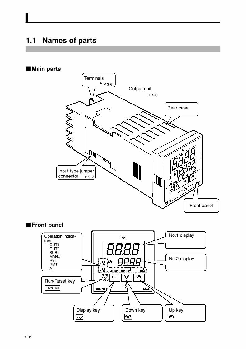
1.1 Names of parts
JJMain parts
P 2-6
P 2-3
P 2-2
Input type jumperconnector
Terminals
Rear case
Output unit
Front panel
JJFront panel
OUT1OUT2SUB1MANURSTRMTAT
Operation indica-tors
Run/Reset key
Display key Down key Up key
No.2 display
No.1 display
RUN/RST

1--3
JJAbout the displays
Displays the process value or parameter symbols.
Displays the set point, manipulated variable or parameter settings.
• OUT1Lights when the pulse output function assigned to “control output 1” isON.
• OUT2Lights when the pulse output function assigned to “control output 2” isON.
• SUB1Lights when the pulse output function assigned to “auxiliary output 1”is ON.
• MANULights in the manual operation mode.
• RSTLights when the control is in reset status.
• RMTLights during remote operation.
• ATFlashes during auto-tuning.
FF No.1 display
FF No.2 display
FF Operation statusindicators

1--4
The following describes basic key operations.
To change to run operation from the reset status, press this key for one se-
cond minimum.To change to the reset status from run operation, press this key for two se-conds minimum.
The functions of this key change according to how long it is pressed. If thekey is pressed for less than one second, the parameters are switched. If the
key is pressed for one second minimum, the menu display appears. In keyoperations from here on, “press the key” refers to pressing the key for lessthan one second.For details on switching of parameters and menu display items, see page
1-10.
Each press of key increments or advances the values or settings on the
No.2 display, while each press of the key decrements or returns thevalues or settings on the No.2 display.
Functions vary, for example, when the RUN/RST key is held down simulta-
neously with the key, or a key is held down continuously. For details,
see page 1-10. Also, chapters 3 and 4 describe examples using various keycombinations.
JJHow to use keys
FF keyRUN/RST
FF key
FF key

1--5
1.2 Input and Output
Alarm 2
Temperatureinput
Voltage input
Current input
Event input
ControllerControl output(heat)
Control output(cool)
Alarm 1
Alarm 3
LBA
Error 1
Error 2
Control output 1
Control output 2
Auxiliaryoutput 1
Transferoutput 1
Input typejumper
LBA
Error 1
Error 2
Error 2
The E5CK-T supports the following inputs:
Temperature input, Current input, Voltage input, and Event input.
FF Temperature input/Voltage input/Current input• Only one of temperature input, current input and voltage input can be
selected and connected to the controller. In the above figure, tempera-ture input is selected.
• The following input sensors can be connected for temperature input:Thermocouple: K, J, T, E, L, U, N, R, S, B, W, PLIIPlatinum resistance thermometer: JPt100, Pt100
• The following currents can be connected for current input:4 to 20 mA, 0 to 20 mA
• The following voltages can be connected for voltage input:1 to 5 VDC, 0 to 5 VDC, 0 to 10 VDC
Add on the input unit (E53---CKB) when using event input. You can select
from the following five event inputs:
Run/Reset, Auto/Manual, Hold/Hold Cancel, Advance, Pattern
JJ Input
FF Event input

1--6
The output functions of the E5CK-T do not operate for five seconds after theE5CK-T is turned ON.
The E5CK-T supports the following five outputs:Control output 1Control output 2Auxiliary output 1Transfer output
When using control output 1 and 2, set the output unit (sold separately).Nine output units are available to suit the output circuit configration.When using transfer output, add on the communication unit (E53-AKF).
• The E5CK---T supports the following twelve output functions:Control output (heat), Control output (cool), Alarms 1 to 3, LBA,Time Signals 1 and 2, Program End, Stage Output,Error 1 (input error), Error 2 (A/D converter error)
• Assign these output functions to control output 1, control output 2 andauxiliary output 1.
• Only control output (heat), control output (cool), alarms 1 to 3 and LBAcan be assigned to control outputs 1 and 2. Only alarms 1 to 3, LBA, error1 and error 2 can be assigned to auxiliary output 1.In the example on the previous page, “control output (heat)” is assignedto ”control output 1”, ”alarm 1” is assigned to ”control output 2”, and”alarm 2” is assigned to ”auxiliary output 1”. Accordingly, the configu-ration is such that heating control output is connected to control output1, and alarm output is connected to control output 2 and auxiliary out-put 1.
• When the control is heating and cooling control, assign ”control output(cool)” to ”control output 1” or ”control output 2”.
• The E5AK---T supports the following four transfer outputs:
Present SP, Process value, Heating side manipulated variable,Cooling side manipulated variable
• These transfer outputs can be output after being scaled. Setting of an up-per limit value smaller than the lower limit value is allowed, so reversescaling can also be carried out.
JJOutput
FF Output assign-ments
FF Transfer output

1--7
1.3 Program
E5CK---T allows you to configure programs made up of a maximum of fourpatterns (pattern 0 to 3) each comprising a maximum of 16 steps.The number of patterns and steps in each pattern can be specified in pa-rameters.
Pattern 3
Pattern 1
Pattern 0
Step 0 Step 1 Step 2 Step 15
• Generally, the “time setup method” is used to configure programs. Bythis method, set points at each step and time are used as program ele-ments. However, the “ramp rise rate setup method” can also be used. Bythis method, the set point, ramp time and soak times are used as programelements.
• Generally, the target patterns are specified before the program isexecuted.
• In parameter setup, you can specify repeated execution of the same pat-tern (Repeat) or consecutive execution of all patterns 0 to 4 (Run all).
• During program operation, steps can be skipped (Advance) and the con-trol monitoring can be paused (Hold).
• Alarms that are assigned as outputs operate referenced to the alarm val-ues preset to each pattern.
• Time signals, program end and stage output can be output according tooutput assignment.
• ON/OFF signals are output as time signals according to the timer thattakes a specified step as its start point.
JJHow programsare structured
JJProgram opera-tion
FF Step operation
JJAlarm output
JJProgram output

1--8
1.4 Parameters and Menus
E5CK-T parameters are distributed between the following ten modes:Protect modeManual modeLevel 0 modeProgram modeLevel 1 modeLevel 2 modeSetup modeExpansion modeOption modeCalibration mode
The settings of parameters in each of eight modes (excluding the protectmode and manual mode) can be checked and modified by selection on themenu display.
The protect function is for preventing unwanted modification of parame-ters, and switching between run and reset operation or auto and manualoperation.
In this mode, the controller can be switched to manual operation. The ma-nipulated variable can be manipulated manually only in this mode.
Set the controller to this mode during normal operation. In this mode, youcan change the set point and pattern during operation, and execute step
operation (e.g. advance). You can only monitor (not change) the processvalue, step No., standby time, pattern elapsing time, pattern executioncount and manipulated variable.
This is the programming mode. In this mode, you can set the number of
steps used in each pattern, pattern execution count, alarm values, setpoints for each step, step time, and time signals for two steps.
This is the main mode for adjusting control. In this mode, you can execute
AT (auto-tuning), and set up the control period, PID parameters.
This is the auxiliary mode for adjusting control. In this mode, you can setthe parameters for limiting the manipulated variable, switch between theremote and local modes, and set the loop break alarm (LBA), alarm hyster-
esis and the digital filter value of inputs.
This is the mode for setting the basic specifications. In this mode, you canset parameters that must be checked or set before operation such as theinput type, scaling, output assignments and direct/reverse operation.
JJParameter types
FF Protect mode
FF Manual mode
FF Level 0 mode
FF Program mode
FF Level 1 mode
FF Level 2 mode
FF Setup mode

1--9
This is the mode for setting expanded functions. In this mode, you can setSP setting limitter, switching between advanced PID control or ON/OFFcontrol, program time unit, selection of step time/rate of rise program-ming, time unit of ramp rise rate, and the time for automatic return to themonitoring display.
This is the mode for setting optional functions. You can select this mode
only when an option unit is mounted in the controller. In this mode, youcan set the communications conditions, transfer output and event inputparameters to match the type of option unit mount in the controller.
This mode is provided so that the user can calibrate inputs and output.When calibrating input, the selected input type is calibrated. Whereas,transfer output can be calibrated only when the communication unit(E53-CKF) is set in the controller.
The following diagram shows the order in which modes are selected.
1 second min.
1 second min.
1 second min.
1 second min.
1 second min.
1 second min.
1 second min.
1 second min.
Level 0 mode
Program mode
Level 2 mode
Setup mode
Expansion mode
Option mode
Calibration mode
Power ON
Level 1 mode
Manual mode
Protect mode
1 second min.
1 second min.
1 second min.
1 second min.
1 second min.
+
+
+
+
+
RUN/RST
RUN/RST
RUN/RST
• To select the menu display in any of the above modes (excluding the pro-tect mode and manual mode), press the key for 1 second minimum.When you have selected the menu display, the previous mode is selected.For example, if you selected the menu display while in the level 0 mode,the No.2 display changes to [ ] as shown on the left.
• To move to the desired mode after you have entered the menu display,select the desired mode using the keys and hold down thekey for one second minimum. The display switches to the first parameterof the mode that you specified.
• Protected modes cannot be selected. Also, the menu display does not ap-pear when modes are protected up to the program mode.
FF Expansion mode
FF Option mode
FF Calibration mode
JJSelecting modes

1--10
• If you select [ ], [ ], [ ] or [ ] in the menu display, thelevel 0, program, level 1 and level 2 modes, respectively, are selected.These modes are selected with control still continuing.
• If you select[ ] [ ] [ ] or [ ] in the menu display, thesetup, expansion, option and calibration modes, respectively, are se-lected.When these modes are selected, the control is reset. So, control outputsand auxiliary output are turned OFF. When another mode is selectedwhile in these modes control, reset is canceled.
• To set the controller to the protect mode or to return to the level 0 mode
from the protect mode, press the RUN/RST key and the key simulta-
neously for 1 second minimum.
• To set the controller to the manual mode, press the key for one se-cond minimum with the key held down in the level 0 to 2 modes. Toreturn to the level 0 mode in the manual mode, press the key for onesecond minimum with the key pressed. Be sure to press the keyfirst in this operation.
• When the controller is not in the manual mode, each press of the keyswitches the parameter in the respective mode.
Parameter1
Parameter2
Parameter3
Parametern
• If you press the key when at the final parameter, the display returnsto the top parameter for the current mode.
• When you change parameter settings or contents, specify the parameterusing the or keys, and either leave the setting for at least twoseconds or press the key. This fixes the setting.
• When another mode is selected, the content of the parameters before themode was selected is fixed.
• When you turn the power OFF, you must first fix the settings and param-eter contents (by pressing the key or selecting another mode). Thesettings and parameter contents are sometimes not changed by merelypressing the or keys.
JJSelectingparameters
JJFixing settings

1--11
1.5 About the Communications Function
The E5CK-T can be provided with a communications function that allowsyou to check and set controller parameters from a host computer. If the
communications function is required, add on the communications unit.For details on the communications function, refer to Chapter 6.
When using the communications function on the RS-232C interface, addon the communications unit (E53-CK01).
When using the communications function on the RS-485 interface, add onthe communications unit (E53-CK03).
FF RS-232C
FF RS-485

1--12
1.6 About Calibration
The E5CK-T controller is calibrated before shipment from the factory. So,the user need not calibrate the E5CK-T controller during regular use.
However, if the E5CK-T controller must be calibrated by the user, use theparameters provided for the user to calibrate temperature input, analoginput (voltage, current) and transfer output. In this case, note that the re-sults of calibration will not be assured.
Also, note that calibration data is updated to the latest value each timethat the E5CK-T controller is calibrated. Calibration data set before ship-ment from the factory cannot be returned to after calibration by the user.
The input type selected in parameters is the item to be calibrated. TheE5CK-T is provided with the following four calibration parameters:
• Thermocouple
• Platinum resistance thermometer
• Current input
• Voltage input
Two parameters are provided for thermocouple and voltage input.
Transfer output also can be calibrated when the communications unit(E53-CKF) is added on.
When calibrating each item, the calibration data is temporarily regis-tered. This data can be registered as final calibration data only when all
items have been newly calibrated. So, all items must be temporarily regis-tered when the E5CK-T controller is calibrated.When registering data, information regarding whether or not calibrationhas been carried out is also registered.
To calibrate these items, the user must prepare separate measuring de-vices and equipment. For details on handling these measuring devices andequipment, refer to the respective manuals.
For details, see Chapter 7 Calibration.
FF Calibratinginputs
FF Calibrating trans-fer output
FF Registering cal-ibration data

CHAPTER 2 PREPARATIONS
2--1
CHAPTER 2PREPARATIONS
This chapter describes the operations (e.g. setup, installation and wir-ing) you should carry out before turning the E5CK-T ON.
CHAPTER2
2.1 Setup 2-2. . . . . . . . . . . . . . . . . . . . . . . . . . . . . . . . .
Draw-out 2-2. . . . . . . . . . . . . . . . . . . . . . . . . . . . . .
Setting the input type jumper 2-2. . . . . . . . . . .
Setting up the output unit 2-3. . . . . . . . . . . . . .
Setting up the option unit 2-3. . . . . . . . . . . . . . .
2.2 Installation 2-4. . . . . . . . . . . . . . . . . . . . . . . . . . . .
Dimensions 2-4. . . . . . . . . . . . . . . . . . . . . . . . . . . .
Panel cutout 2-4. . . . . . . . . . . . . . . . . . . . . . . . . . .
Mounting 2-5. . . . . . . . . . . . . . . . . . . . . . . . . . . . .
2.3 Wiring Terminals 2-6. . . . . . . . . . . . . . . . . . . . . .
Terminal arrangement 2-6. . . . . . . . . . . . . . . . .
Precautions when wiring 2-6. . . . . . . . . . . . . . .
Wiring 2-6. . . . . . . . . . . . . . . . . . . . . . . . . . . . . . . .

2--2
2.1 Setup
The following section describes how to draw out the internal mechanismfrom the housing and how to set the input type jumper.
Draw out the internal mechanism from the housing.
(1) Press in both of the hooks on the left and right sides of the front panel
to unlock the internal mechanism from the housing.
(2) Draw out the internal mechanism towards you holding both sides of
the front panel.
JJSetting the input type jumper• For details on where the input type jumper is located, see the figure on
page 1---2.• Set the jumper to one of temperature input, voltage input or current in-
put matched to the type of sensor connected to the input terminal.I : Current input V : Voltage input
TC/PT : Temperature input
• The input type jumper is factory---set to “TC/PT (temperature input)”.• When you disconnect or insert the input type jumper, do not hold it di-
rectly by its pins.• When you have finished setting the input type jumper, insert the inter-
nal mechanism back into the housing.• To do this, push in the internal mechanism until you hear the hooks on
the front panel snap into place.
JJDraw-out

2--3
JJSetting up the output unitThe following table shows the output units that can be set in the E5CKcontroller.
Model Specifications(control output 1/control output 2)
E53-R4R4E53-Q4R4E53-Q4HR4E53-C4R4E53-C4DR4E53-V44R4E53-Q4Q4E53-Q4HQ4H
Relay/RelayVoltage (NPN)/RelayVoltage (PNP)/Relay4 to 20 mA/Relay0 to 20 mA/Relay0 to 10 V/RelayVoltage (NPN)/Voltage (NPN)Voltage (PNP)/Voltage (PNP)
FF Setup(1) Two rectangular holes for slotting are pro-
vided on the power board (on right side ofcontroller). Fit the two protrusions on theoutput unit into these two holes.
(2) With the output unit fitted into the powerboard, fit the output unit into the connectoron the control board (on left side of control-
ler).
JJSetting up the option unitThe following table shows the option units that can be connected to theE5CK controller.
Unit Model Specifications
Communications unitCommunications unitInput unitCommunications unit
E53-CK01E53-CK03E53-CKBE53-CKF
Communications (RS-232C)Communications (RS-485)Event input: 1 inputTransfer output: 4 to 20 mA
FF Setup(1) Place the controller with its bottom facing
up, and fit the board horizontally into theconnector on the power board (on right sideof controller).
(2) With the power board connected, fit theboard vertically into the connector on thecontrol board (on left side of controller).
FF Output unit list
FF Option unit list

CHAPTER 2 PREPARATIONS
2--4
2.2 Installation
JJDimensions5853j 13 100
44.8
48
j
PV
SVOUT1
OUT2 MANU STOP RMT AT SUB1
RUN
E5CK
RST
AM
JJPanel cutout
• Recommended panel thickness is 1 to 5mm.
• Maintain the specified vertical and hori-zontal mounting space between each con-troller.Controllers must not be closely mountedvertically or horizontally.
45 +0.60
45 +0.60
Unit (mm)65 min.
60 min.

2.2 Installation
2--5
JJMountingAdapter
Panel
Watertightpacking
(1) Insert the E5CK controller into the mounting hole in the panel at theposition shown in the figure above.
(2) Push the adapter along the controller body from the terminals up tothe panel, and fasten temporarily.
(3) Tighten the two fixing screws on the adapter. When tighteningscrews, tighten the two screws alternately keeping the torque toapproximately 0.29 to 0.39 N·m, or 3 to 4 kgf·cm.
E5CK-AA1-500 controller is provided with a terminal cover (E53-COV07). Fastthe terminal cover as follows by using the snap pin.
About the TerminalCover
CHAPTER 2 PREPARATIONS
2--6
2.3 Wiring Terminals
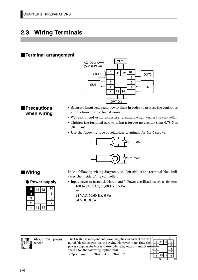
JJTerminal arrangement
5
4
3
2
1
10
9
8
7
613 14
11 12
OUT1
OUT2
SUB1
OPTION
IN
AC100-240V(AC/DC24V )
SOURCE
• Separate input leads and power lines in order to protect the controllerand its lines from external noise.
• We recommend using solderless terminals when wiring the controller.
• Tighten the terminal screws using a torque no greater than 0.78 N¡m(8kgf¡cm).
• Use the following type of solderless terminals for M3.5 screws.
7.2mm max.
7.2mm max.
In the following wiring diagrams, the left side of the terminal Nos. indi-cates the inside of the controller.
• Input power to terminals Nos. 4 and 5. Power specifications are as follows:100 to 240 VAC, 50/60 Hz, 15 VAor24 VAC, 50/60 Hz, 6 VA24 VDC, 3.5W
The E5CK has independent power supplies for each of the ter-minal blocks shown on the right. However, note that thepower supplies for blocks C (exclude relay output) and D areshared for the following option unit.• Option unit : E53---CKB or E53---CKF
About the powerblocks
A C54321
109876
C
D B
11 12
13 14
JJPrecautionswhen wiring
JJWiring
FF Power supply
5
4321
10
987613 14
11 12

2.3 Wiring Terminals
2--7
• Connect the sensor input to terminal Nos. 6 to 8 as follows according tothe input type.
8
7
6
8
7
6
8
7
6
8
7
6
-
+
-
+
-
+V mA
TC ⋅ PT V I
Thermocouple Platinum resistancethermometer
Voltage input Current input
• Set the input type jumper inside the controller matched to the inputtype. Set thermocouples and platinum resistance thermometer as tem-perature input to the shared jumper setting (TC/PT). For details on theinput type jumper, see page 2---2.
• Terminal Nos. 11 and 12 are for control output 1 (OUT1). The followingdiagrams show the available outputs and their internal equalizing circuits.
11
12
11
12
L
11
12
L
11
12
L
11
12
L
E53-R4R4 E53-Q4R4E53-Q4Q4
E53-Q4HR4E53-Q4HQ4H
E53-V44R4 E53-C4R4E53-C4DR4
NPN PNP 0 to 10V 4 to 20mA
+v+
-
+
-
+
-
+
-GND
mA
Relay
V
GND
+v
• Terminal Nos. 9 and 10 are for control output 2 (OUT2). The followingdiagrams show the available outputs and their internal equalizing cir-cuits.
10
9
10
9
L
10
9
L
+v+
-
+
-GND
E53-Q4Q4 E53-Q4HQ4H
NPN PNP
E53-R4R4 /E53-V44R4E53-Q4R4 /E53-C4R4E53-Q4HR4/E53-C4DR4
RelayGND
+v
• The following table shows the specifications for each output type.
Output Type Specifications
RelayVoltage (NPN)Voltage (PNP)
250VAC, 3 A12VDC, 20 mA (with short-circuit protection)12VDC, 20 mA (with short-circuit protection)
0 to 10V
4 to 20mA
0 to 10VDC, Permissible load impedance:1 kΩ min., Resolution: Approx. 2600
4 to 20 mA, Permissible load impedance:500 Ω max., Resolution: Approx. 2600
FF Input
5
4321
10
987613 14
11 12
FF Control output5
4321
10
987613 14
11 12

CHAPTER 2 PREPARATIONS
2--8
• Terminal Nos.2 and 3 are for auxiliary output 1 (SUB1).
• The internal equalizing circuit for auxiliary output 1 is as follows:
3
2
• Relay specifications are as follows:1a, 250 VAC, 1 A
• Terminal Nos.1, 13 and 14 are available only for controllers that supportoptional functions.
• These terminals can be wired as follows depending on the controllertype.
13
14
1
13
14
1
13
14
1
13
14
1
SD
RD
SG
A
B
+
--4 to 20mA
E53-CK01
RS-232C
E53-CK03
RS-485
E53-CKB E53-CKF
Event input Transfer output
• For details on the RS-232C and RS-485 communications functions, seeChapter 6, Using the Communications Functions.
• Use event inputs under the following conditions:
Contact input ON: 1kΩmax., OFF: 100 kΩ max.
No-contact input ON: residual voltage 1.5 V max., OFF: leakage current 0.1 mAmax.
Polarities during no-contact input are as follows:
13
14
1
+
--
• Transfer output specifications are as follows:4 to 20 mA DC, Permissible load impedance: 500Ω max., Resolution:Approx. 2600
FF Auxiliary output 1
54321
10987613 14
11 12
FF Option
5
4321
10
987613 14
11 12

CHAPTER 3 BASIC OPERATION
3--1
CHAPTER 3BASIC OPERATION
This chapter describes actual examples for understanding the basic op-eration of the E5CK-T.
CHAPTER3
3.1 Convention Used in this Chapter 3-2. . . . . . . .
3.2 Setting Input Specifications 3-4. . . . . . . . . . . . .
Input type 3-4. . . . . . . . . . . . . . . . . . . . . . . . . . . . .
Temperature input 3-5. . . . . . . . . . . . . . . . . . . . .
Analog input 3-5. . . . . . . . . . . . . . . . . . . . . . . . . .
3.3 Setting Output Specifications 3-7. . . . . . . . . . .
Output assignments 3-7. . . . . . . . . . . . . . . . . . . .
Direct/reverse operation 3-7. . . . . . . . . . . . . . . .Control period 3-8. . . . . . . . . . . . . . . . . . . . . . . . .
3.4 Setting Alarm Type 3-9. . . . . . . . . . . . . . . . . . . .
Alarm type 3-9. . . . . . . . . . . . . . . . . . . . . . . . . . . .
Alarm value 3-9. . . . . . . . . . . . . . . . . . . . . . . . . . .
Alarm hysteresis 3-10. . . . . . . . . . . . . . . . . . . . . . .
Close in alarm/open in alarm 3-10. . . . . . . . . . . .
3.5 Setting Patterns 3-13. . . . . . . . . . . . . . . . . . . . . . .
Pattern No. 3-14. . . . . . . . . . . . . . . . . . . . . . . . . . . .
Number of steps 3-14. . . . . . . . . . . . . . . . . . . . . . .
Step SP/Step time 3-14. . . . . . . . . . . . . . . . . . . . . .
Alarm value 3-15. . . . . . . . . . . . . . . . . . . . . . . . . . .
3.6 Protect Mode 3-18. . . . . . . . . . . . . . . . . . . . . . . . . .
Security 3-18. . . . . . . . . . . . . . . . . . . . . . . . . . . . . . .
Key protect 3-18. . . . . . . . . . . . . . . . . . . . . . . . . . . .
3.7 Starting and Stopping Operation 3-20. . . . . . . .
3.8 Adjusting Control Operation 3-21. . . . . . . . . . . .
Changing programs 3-21. . . . . . . . . . . . . . . . . . . .
Manual operation 3-23. . . . . . . . . . . . . . . . . . . . . .Auto-tuning (A.T.) 3-24. . . . . . . . . . . . . . . . . . . . .

3--2
3.1 Convention Used in this Chapter
This chapter describes basic E5CK-T operations such as how to set up pa-rameters, start and stop operation, and adjust control operation.
For more complex control examples, refer to Chapter 4 Applied Operationand Chapter 5 Parameters.
The following diagram shows the basic flow of operation.
Power ON
Setup
Setting input specifications
Setting output specifications
Setting alarm output
Protecting parameters
Operation
Start
Adjustment
Stop
Power OFF
Setting patterns
The descriptions in this chapter follow the order of basic operations shownin the flow above. Examples of operation of each of the items are describedup to completion of parameter setup. However, you must move to the topparameter of the following Setting. For example, when you have finished
“setting input specifications” and you want to “set output specifications,”move to the top parameter of “setting output specifications” from the bot-tom parameter of “setting input specifications.”
For details on moving to parameters between items, refer Chapter, Select-ing modes and Selecting parameters (page 1-10).
FF Basic OperationFlow

3--3
This description assumes that the controller is operated under the follow-ing conditions.
• A K thermocouple is used as the input.
• Control output (heat), alarm 1 and alarm 2 functions are assigned to“control output 1,” “control output 2” and auxiliary output 1, respec-tively. Of these, only control output 1 and auxiliary output 1 are used.
• The relay output unit is mounted at control output 1.
• The upper-limit alarm is set as alarm 2. The alarm is output when thetemperature exceeds 10_C with respect to the PV.
• The program is made up of one pattern comprising four steps.
• The following figures show terminal wiring and the program used in thesetting examples.
5
4
3
2
1
10
9
8
7
613 14
11 12
OUT1
OUT2
Humidifier Control target
Temperature sensorK thermocouple
Alarm 1(deviation upper-andlower-limit)
E5CK--T
AC100-240V(AC/DC24V )
Step 1 Step 2 Step 3
Pattern 0
Time: hr, min
0.20 0.40 0.20
50
100
SP
FF Setup examples
CHAPTER 3 BASIC OPERATION
3--4
3.2 Setting Input Specifications
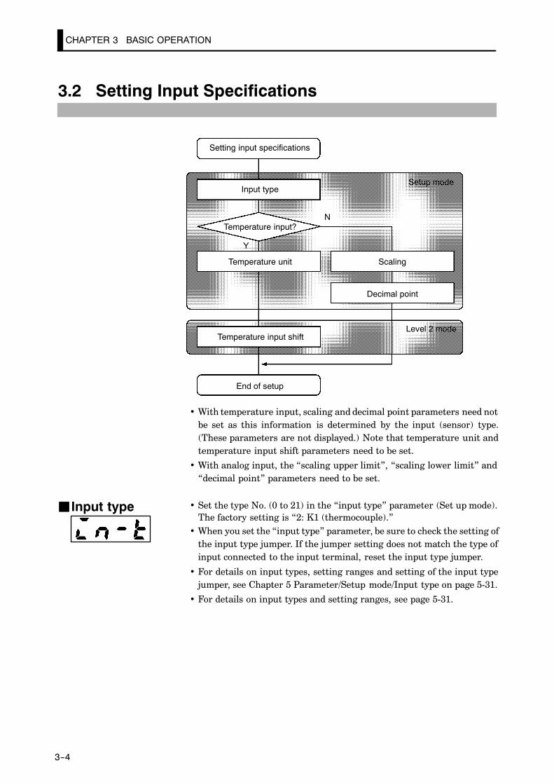
Setting input specifications
Input type
Temperature input?
Temperature unit
Temperature input shift
End of setup
Decimal point
Scaling
Setup mode
Level 2 mode
N
Y
• With temperature input, scaling and decimal point parameters need notbe set as this information is determined by the input (sensor) type.(These parameters are not displayed.) Note that temperature unit andtemperature input shift parameters need to be set.
• With analog input, the “scaling upper limit”, “scaling lower limit” and“decimal point” parameters need to be set.
• Set the type No. (0 to 21) in the “input type” parameter (Set up mode).The factory setting is “2: K1 (thermocouple).”
• When you set the “input type” parameter, be sure to check the setting ofthe input type jumper. If the jumper setting does not match the type ofinput connected to the input terminal, reset the input type jumper.
• For details on input types, setting ranges and setting of the input typejumper, see Chapter 5 Parameter/Setup mode/Input type on page 5-31.
• For details on input types and setting ranges, see page 5-31.
JJ Input type
3.2 Setting Input Specifications
3--5
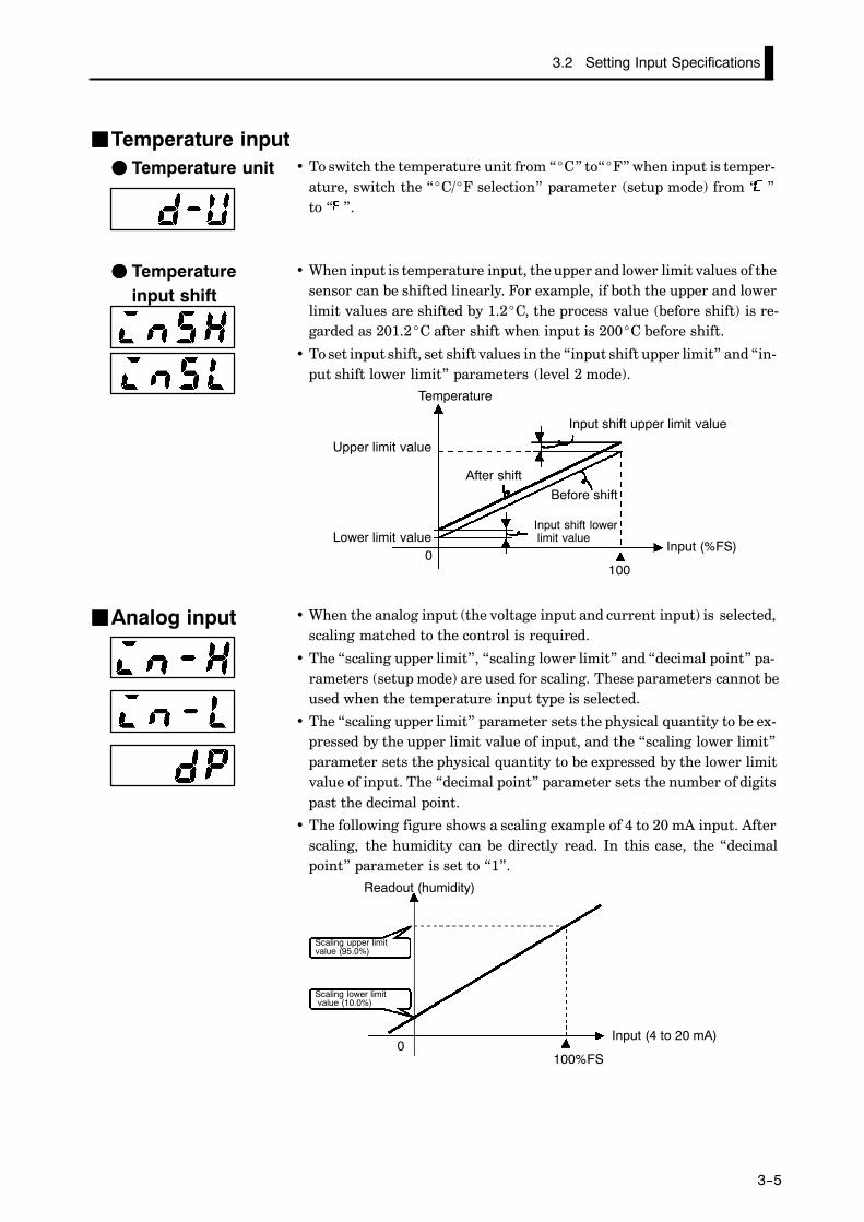
JJTemperature input• To switch the temperature unit from “_C” to“_F” when input is temper-
ature, switch the “_C/_F selection” parameter (setup mode) from “ ”to “ ”.
• When input is temperature input, the upper and lower limit values of thesensor can be shifted linearly. For example, if both the upper and lowerlimit values are shifted by 1.2_C, the process value (before shift) is re-garded as 201.2_C after shift when input is 200_C before shift.
• To set input shift, set shift values in the “input shift upper limit” and “in-put shift lower limit” parameters (level 2 mode).
0100
Temperature
Upper limit value
Lower limit value
Input shift upper limit value
After shiftBefore shift
Input shift lowerlimit value
Input (%FS)
• When the analog input (the voltage input and current input) is selected,scaling matched to the control is required.
• The “scaling upper limit”, “scaling lower limit” and “decimal point” pa-rameters (setup mode) are used for scaling. These parameters cannot beused when the temperature input type is selected.
• The “scaling upper limit” parameter sets the physical quantity to be ex-pressed by the upper limit value of input, and the “scaling lower limit”parameter sets the physical quantity to be expressed by the lower limitvalue of input. The “decimal point” parameter sets the number of digitspast the decimal point.
• The following figure shows a scaling example of 4 to 20 mA input. Afterscaling, the humidity can be directly read. In this case, the “decimalpoint” parameter is set to “1”.
100%FS0
Readout (humidity)
Scaling upper limitvalue (95.0%)
Scaling lower limitvalue (10.0%)
Input (4 to 20 mA)
FF Temperature unit
FF Temperatureinput shift
JJAnalog input

CHAPTER 3 BASIC OPERATION
3--6
In this example, let’s check the input type and temperature units, and shiftthe lower limit by 1_C and the upper limit by 3_C.
“input type” = “2: K1”“temperature unit” = “_C”
“input shift upper limit” = “3.0”“input shift lower limit” = “1.0”
(1) Select the menu display, and select “ : setup mode” using theor keys. For details on selecting the menu display, see page
1-10.
(2) Press the key for one second minimum to enter the setup mode.The top parameter in the setup mode “ : input type” is displayed.This parameter is factory-set to “2: K1”.
(3) Press the key to fix the set value. The display changes to “ :_C/_F selection” parameter. This parameter is factory-set to “ : _C”.
(4) Select the menu display, and select “ : level 2 mode” using the
or keys.
(5) Press the key for one second minimum to enter the level 2 mode.The top parameter in the level 2 mode [ ] (“local/remote” pa-
rameter) is displayed.
(6) Press the key until [ ] (“input shift upper limit” parameter)is selected. This parameter is factory-set to “0.0”.
(7) Press the key until “3.0” is displayed.
(8) Press the key until [ ] (“input shift lower limit” parameter)is selected. This parameter is factory-set to “0.0”.
(9) Press the key until “1.0” is displayed. This sets the “input shift
upper limit” and “input shift lower limit” values.
Setting Example
1 second min.
1 second min.
1 second min.
3.3 Setting Output Specifications
3--7
3.3 Setting Output Specifications
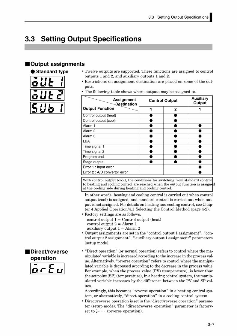
JJOutput assignments• Twelve outputs are supported. These functions are assigned to control
outputs 1 and 2, and auxiliary outputs 1 and 2.• Restrictions on assignment destination are placed on some of the out-
puts.• The following table shows where outputs may be assigned to.
AssignmentDestination
Output Function
Control Output AuxiliaryOutputDestination
Output Function 1 2 1Control output (heat) F F
Control output (cool) F F
Alarm 1 F F F
Alarm 2 F F F
Alarm 3 F F F
LBA F F F
Time signal 1 F F F
Time signal 2 F F F
Program end F F F
Stage output F F F
Error 1 : Input error F
Error 2 : A/D convertor error F
With control output (cool), the conditions for switching from standard controlto heating and cooling control are reached when the output function is assignedat the cooling side during heating and cooling control.
In other words, heating and cooling control is carried out when controloutput (cool) is assigned, and standard control is carried out when out-put is not assigned. For details on heating and cooling control, see Chap-ter 4 Applied Operation/4.1 Selecting the Control Method (page 4-2).
• Factory settings are as follows:control output 1 = Control output (heat)control output 2 = Alarm 1auxiliary output 1 = Alarm 2
• Output assignments are set in the “control output 1 assignment”, “con-trol output 2 assignment”, “ auxiliary output 1 assignment” parameters(setup mode).
• “Direct operation” (or normal operation) refers to control where the ma-nipulated variable is increased according to the increase in the process val-ue. Alternatively, “reverse operation” refers to control where the manipu-lated variable is decreased according to the decrease in the process value.For example, when the process value (PV) (temperature), is lower thanthe set point (SP) (temperature), in a heating control system, the manip-ulated variable increases by the difference between the PV and SP val-ues.Accordingly, this becomes “reverse operation” in a heating control sys-tem, or alternatively, “direct operation” in a cooling control system.
• Direct/reverse operation is set in the “direct/reverse operation” parame-ter (setup mode). The “direct/reverse operation” parameter is factory-set to (reverse operation).
FF Standard type
JJDirect/reverseoperation
CHAPTER 3 BASIC OPERATION
3--8
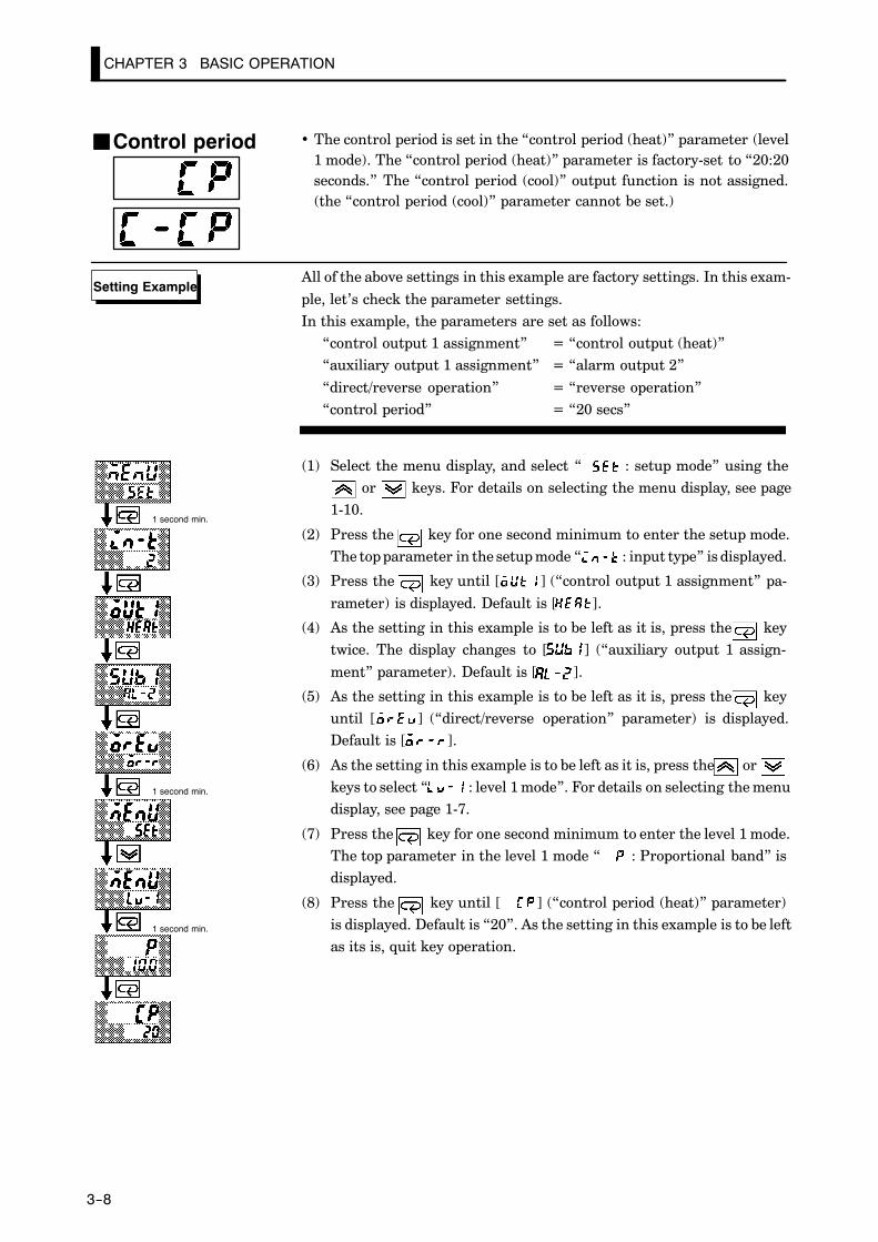
• The control period is set in the “control period (heat)” parameter (level1 mode). The “control period (heat)” parameter is factory-set to “20:20seconds.” The “control period (cool)” output function is not assigned.(the “control period (cool)” parameter cannot be set.)
All of the above settings in this example are factory settings. In this exam-
ple, let’s check the parameter settings.In this example, the parameters are set as follows:
“control output 1 assignment” = “control output (heat)”“auxiliary output 1 assignment” = “alarm output 2”
“direct/reverse operation” = “reverse operation”“control period” = “20 secs”
(1) Select the menu display, and select “ : setup mode” using theor keys. For details on selecting the menu display, see page
1-10.
(2) Press the key for one second minimum to enter the setup mode.The top parameter in the setup mode “ : input type” is displayed.
(3) Press the key until [ ] (“control output 1 assignment” pa-
rameter) is displayed. Default is [ ].
(4) As the setting in this example is to be left as it is, press the keytwice. The display changes to [ ] (“auxiliary output 1 assign-
ment” parameter). Default is [ ].
(5) As the setting in this example is to be left as it is, press the keyuntil [ ] (“direct/reverse operation” parameter) is displayed.Default is [ ].
(6) As the setting in this example is to be left as it is, press the orkeys to select “ : level 1 mode”. For details on selecting the menudisplay, see page 1-7.
(7) Press the key for one second minimum to enter the level 1 mode.The top parameter in the level 1 mode “ : Proportional band” isdisplayed.
(8) Press the key until [ ] (“control period (heat)” parameter)is displayed. Default is “20”. As the setting in this example is to be leftas its is, quit key operation.
JJControl period
Setting Example
1 second min.
1 second min.
1 second min.

3.4 Setting Alarm Type
3--9
3.4 Setting Alarm Type
• Three alarm outputs are supported: alarms 1 to 3. Of these, only thealarm assigned as the output can be used.
• Alarm output conditions are determined according to the combinationof the “alarm type”, “alarm value” and “alarm hysteresis” parametersettings.
• The contact conditions for when alarm output is ON can be set to “open”or “closed” in the “close in alarm/open in alarm” parameter.
• The following table shows the alarm types supported by the E5CK-Tcontroller and their respective operations.
Alarm TypeAlarm Output Operation
Alarm TypeWhen X is positive When X is negative
1 Upper-and lower-limit alarm(deviation)
ONOFF
X X
SPAlways ON
2 Upper-limit alarm(deviation)
ONOFF
X
SP
ONOFF
X
SP
3 Lower-limit alarm(deviation)
ONOFF
X
SP
XONOFF
SP
4 Upper-and-lower-limit rangealarm (deviation)
ONOFF
X X
SPAlways OFF
5Upper-and-lower-limit alarmwith standby sequence(deviation)
ONOFF
X X
SPAlways OFF
6 Upper-limit alarm with stand-by sequence (deviation)
ONOFF
X
SP
ONOFF
X
SP
7 Lower-limit alarm with stand-by sequence (deviation)
ONOFF
X
SP
ONOFF
X
SP
8 Absolute-value upper-limitalarm
ONOFF
X
0
ONOFF
X
0
9 Absolute-value lower-limitalarm
ONOFF
X
0ONOFF
X
0
10 Absolute-value upper-limitalarm with standby sequence
ONOFF
X
0
ONOFF
X
0
11 Absolute-value lower-limitalarm with standby sequence
ONOFF
X
0
ONOFF
X
0
• Alarm types are set independently for each alarm in the “alarm 1 to 3”parameters (setup mode). Default is “2: Upper-limit alarm (devica-tion)”.
• Alarm values are indicated by “X” in the table above. Alarm output op-eration differs according to whether the value of the alarm is positive ornegative.
• Alarm values are built into the program and are set for each pattern. Fordetails, see 3.5 Setting Patterns” (page 3-14).
JJAlarm type
JJAlarm value
CHAPTER 3 BASIC OPERATION
3--10
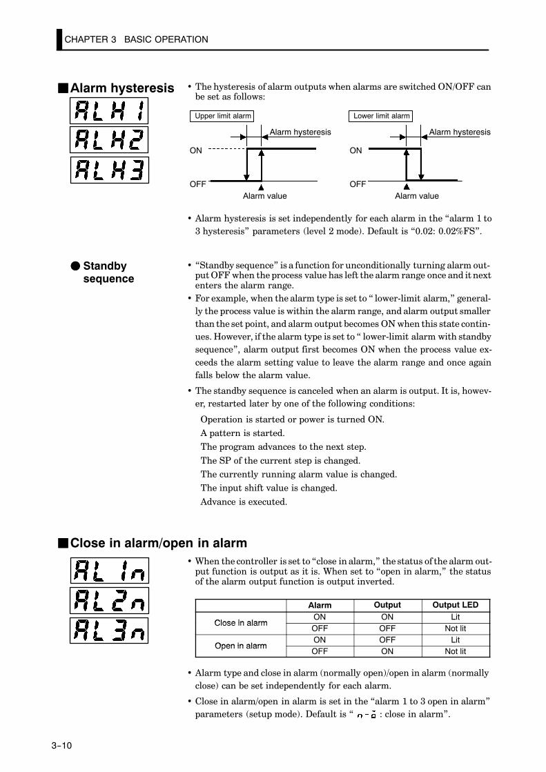
• The hysteresis of alarm outputs when alarms are switched ON/OFF canbe set as follows:
ON
OFF
Alarm hysteresis
Alarm value Alarm value
ON
OFF
Upper limit alarm Lower limit alarm
Alarm hysteresis
• Alarm hysteresis is set independently for each alarm in the “alarm 1 to3 hysteresis” parameters (level 2 mode). Default is “0.02: 0.02%FS”.
• “Standby sequence” is a function for unconditionally turning alarm out-put OFF when the process value has left the alarm range once and it nextenters the alarm range.
• For example, when the alarm type is set to “ lower-limit alarm,” general-ly the process value is within the alarm range, and alarm output smallerthan the set point, and alarm output becomes ON when this state contin-ues. However, if the alarm type is set to “ lower-limit alarm with standbysequence”, alarm output first becomes ON when the process value ex-ceeds the alarm setting value to leave the alarm range and once againfalls below the alarm value.
• The standby sequence is canceled when an alarm is output. It is, howev-er, restarted later by one of the following conditions:
Operation is started or power is turned ON.A pattern is started.The program advances to the next step.
The SP of the current step is changed.The currently running alarm value is changed.The input shift value is changed.
Advance is executed.
JJClose in alarm/open in alarm• When the controller is set to “close in alarm,” the status of the alarm out-
put function is output as it is. When set to “open in alarm,” the statusof the alarm output function is output inverted.
Alarm Output Output LED
Close in alarmON ON Lit
Close in alarmOFF OFF Not lit
Open in alarmON OFF Lit
Open in alarmOFF ON Not lit
• Alarm type and close in alarm (normally open)/open in alarm (normallyclose) can be set independently for each alarm.
• Close in alarm/open in alarm is set in the “alarm 1 to 3 open in alarm”parameters (setup mode). Default is “ : close in alarm”.
JJAlarm hysteresis
FF Standbysequence

3.4 Setting Alarm Type
3--11
The figure below visually summarizes the above descriptions of alarm op-erations (when alarm type is set to “lower-limit alarm with standby se-quence”):
Alarm type: lower limit alarm withstandby sequence
Alarm value
Alarm
Standby sequencecanceled
PV
Alarm hysteresis
Time
ON
OFF (open)output
ON (closed)
OFF
FF Summary ofalarm operations

CHAPTER 3 BASIC OPERATION
3--12
Alarm 2 is output when the temperature exceeds alarm value 2 pro-grammed to the SP. Parameter factory settings for “alarm type 2,” “alarmhysteresis” and “close in alarm/open in alarm” are used.In this example, the related parameters are set as follows:
“alarm type 2” = “2: upper-limit”“alarm value 2” = (set in program setting)“alarm hysteresis: = “0.02”“close in alarm/open in alarm” = “ : close in alarm”
In this example, let’s check the alarm type.
(1) Select the menu display, and select “ : setup mode” pressing the
or keys. For details on selecting the menu display, see page1-9.
(2) Press the key to enter the setup mode. The top parameter in thesetup mode “ : input type” is displayed.
(3) Press the key until [ ] (“alarm type 2” parameter) is dis-played. Default is “2: upper limit”.
Setting Example
1 second min.
3.5 Setting Patterns
3--13
3.5 Setting Patterns
If you want to set parameters in the program mode during controller operation, you must first stop operation.Operation may continue only in special instances, for example, to change SP during controller operation.
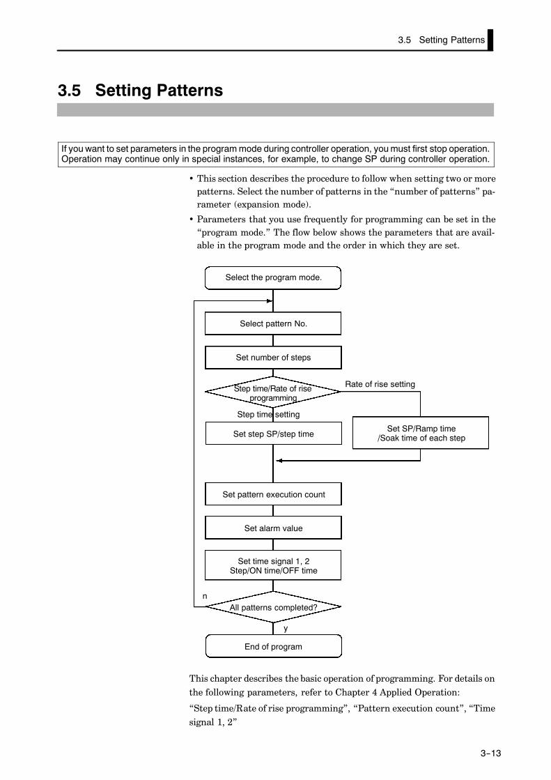
• This section describes the procedure to follow when setting two or morepatterns. Select the number of patterns in the “number of patterns” pa-rameter (expansion mode).
• Parameters that you use frequently for programming can be set in the“program mode.” The flow below shows the parameters that are avail-able in the program mode and the order in which they are set.
Select the program mode.
Select pattern No.
Set number of steps
Step time/Rate of riseprogramming
Set step SP/step time
Set pattern execution count
Set alarm value
Set time signal 1, 2Step/ON time/OFF time
All patterns completed?
End of program
Set SP/Ramp time/Soak time of each step
Step time setting
n
y
Rate of rise setting
This chapter describes the basic operation of programming. For details onthe following parameters, refer to Chapter 4 Applied Operation:
“Step time/Rate of rise programming”, “Pattern execution count”, “Timesignal 1, 2”
CHAPTER 3 BASIC OPERATION
3--14
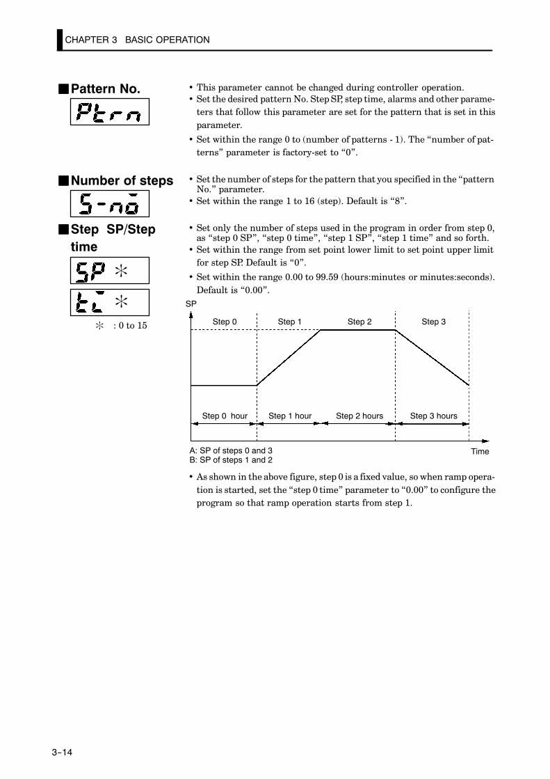
• This parameter cannot be changed during controller operation.• Set the desired pattern No. Step SP, step time, alarms and other parame-
ters that follow this parameter are set for the pattern that is set in thisparameter.
• Set within the range 0 to (number of patterns - 1). The “number of pat-terns” parameter is factory-set to “0”.
• Set the number of steps for the pattern that you specified in the “patternNo.” parameter.
• Set within the range 1 to 16 (step). Default is “8”.
• Set only the number of steps used in the program in order from step 0,as “step 0 SP”, “step 0 time”, “step 1 SP”, “step 1 time” and so forth.
• Set within the range from set point lower limit to set point upper limitfor step SP. Default is “0”.
• Set within the range 0.00 to 99.59 (hours:minutes or minutes:seconds).Default is “0.00”.
Step 0 hour
SP
Step 1 hour Step 2 hours Step 3 hours
Step 0 Step 1 Step 2 Step 3
TimeA: SP of steps 0 and 3B: SP of steps 1 and 2
• As shown in the above figure, step 0 is a fixed value, so when ramp opera-tion is started, set the “step 0 time” parameter to “0.00” to configure theprogram so that ramp operation starts from step 1.
JJPattern No.
JJNumber of steps
JJStep SP/Steptime
:
:
: : 0 to 15

The decimal point of the alarm value conforms to the setting of the “decimal poinparameter. In this example, the “decimal point” parameter is set to “1”. (Durintemperature input, the decimal point of the alarm value conforms to the set senso
About the AlarmValue DecimalPoint
3.5 Setting Patterns
3--15
• Alarm values can be set only for alarms that have been assigned as out-put.
• When a deviation alarm is assigned as output, the alarm value is set withrespect to SP. The following example shows the relationship between theSP and alarm value when the alarm type is set to “upper limit.”
SP
Step 0 Step 1 Step 2
Step 1 SP
Step 0 SP
Alarm type: upper-limit alarm
Alarm value
Time
JJAlarm value
:
: : 0 to 3

CHAPTER 3 BASIC OPERATION
3--16
In this example, let’s set the next program to pattern 0.
Step 1 Step 2 Step 3
Time: hr, min
0.20 0.40 0.20
50
100
SP
SP Time(hr, min.)
Alarmvalue 2
Step 0 50 0.00 10Step 1 100 0.20 10Step 2 100 0.40 10Step 3 50 0.20 10
(1) Select the menu display, and select “ : program” pressing the
or keys. For details on selecting the menu display, see page 1-10.
(2) Press the key to enter the program mode. The top parameter inthe program mode “ : pattern” is displayed. Default is “0 : pat-
tern 0”.
(3) As the setting “0: pattern 0” in this example is to be left as it is, pressthe key. The display changes to the [ ] (“number of steps” pa-rameter). Default is “8”.
(4) Set the parameter to “4” pressing the or keys.
(5) When you press the , the display changes to the [ ] (“step 0 SP”
parameter). Default is “0”.
(6) Set the parameter to “50” pressing the or keys.
(7) When you press the , the display changes to the [ ] (“step 0
time” parameter). Default is “0.00”.
(8) As the setting “0.00: 0 minutes” in this example is to be left as it is,press the key. The display changes to the [ ] (“step 1 SP” pa-
rameter). Default is “0”.
(9) Set the parameter to “100” pressing the or keys.
(10) In the same way, set the “ : step 1 time”, “ : step 2 SP”, “
: step 2 time”, “ : step 3 SP”, “ : step 3 time” parameters, inthat order.
(11) When you have finished setting the step SPs and times press the
key. The [ ] (“pattern execution count” parameter, is displayed.Default is “1”.)
• Pattern execution count
• Time signals are not use
Setting Example
1 second min.

3.5 Setting Patterns
3--17
(12) As the setting in this example is to be left as it is, set the alarm value.Press the key until [ ] (“alarm 2” parameter) is displayed.Default is “0”.
(13) Set the parameter to “10: 10 seconds” pressing the or keys.

CHAPTER 3 BASIC OPERATION
3--18
3.6 Protect Mode
• This parameter allows you to protect until start of operation parametersthat do not change during operation to prevent unwanted modification.
• The set value of the “security” parameter (protect mode) limits therange of protectable parameters. The following table shows the relation-ship between set values and the range of protection. (Only modesmarked by F can be operated.)
ModeSet value
Mode0 1 2 3 4 5 6
Calibration F F
Option F F
Expansion F F
Setup F F
Level 2 F F F
Level 1 F F F F
Program F F F F F
Level 0 F F F F F F *1
*1 Only the “PV/Present SP” parameter can be displayed.
• When this parameter is set to “0”, parameters are not protected.
• When this parameter is set to “5”, operations in only the level 0 mode canbe selected, and the mode is not displayed on the menu display.
• When this parameter is set to “6”, the “PV/Present SP” parameter canonly be monitored.
• Default is “1”.
• This parameter disables key operation for switching run/reset or auto/manual. For example, if you protect the key operation for switchingauto/manual by the “key protect” parameter (protect mode) during au-tomatic operation, the controller cannot be set to the manual mode, pre-venting manual operation of the controller during operation.
• The following table shows the relationship between set values and keysthat are protected.
Set value Description
0 Key protection OFF1 A/M cannot be selected.2 RUN/RST cannot be selected.3 Both A/M and RUN/RST cannot be selected.
• Default is “0 : All keys can be operated.”
JJSecurity
JJKey protect
3.6 Protect Mode
3--19
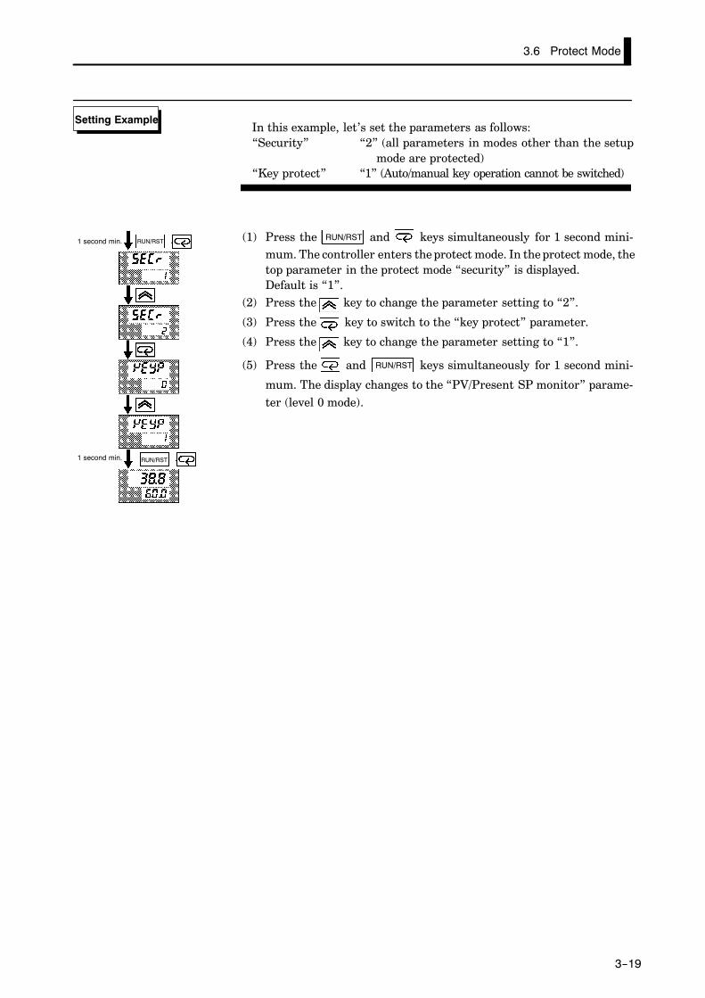
In this example, let’s set the parameters as follows:“Security” “2” (all parameters in modes other than the setup
mode are protected)“Key protect” “1” (Auto/manual key operation cannot be switched)
(1) Press the RUN/RST and keys simultaneously for 1 second mini-mum. The controller enters the protect mode. In the protect mode, thetop parameter in the protect mode “security” is displayed.Default is “1”.
(2) Press the key to change the parameter setting to “2”.
(3) Press the key to switch to the “key protect” parameter.
(4) Press the key to change the parameter setting to “1”.
(5) Press the and RUN/RST keys simultaneously for 1 second mini-
mum. The display changes to the “PV/Present SP monitor” parame-ter (level 0 mode).
Setting Example
RUN/RST
RUN/RST
1 second min.
1 second min.

On the E53-CKB, run/reset can be selected by event input.For details on how to use event input, see 4.7 How to Use Event Input, page 4-1
Using Event Input
CHAPTER 3 BASIC OPERATION
3--20
3.7 Starting and Stopping Operation
• To start program operation (that is, switch from the reset state to run
operation), press the RUN/RST key for one second minimum.
• To stop program operation (that is, switch from run operation to the re-
set state), press the RUN/RST key from two seconds minimum. When the
controller has stopped operating (reset state), the RST LED lights.
• The controller cannot be reset during auto-tuning (A.T.).
• Specify the manipulated variable (-5.0 to 105.0%) in the “MV at reset”parameter (level 2 mode) to output the manipulated variable duringreset. Default is “0.0:0.0%”.
• When the controller is reset in the manual mode, the manual MV takesprecedence.
• Both the MV limitter and MV change rate limitter are ineffective againstthe manipulated value at reset.
RUN/RST
FF Manipulated vari-able at reset

If you set the “number of steps” parameter (program mode) to a value smaller ththe current number of steps during program operation, program operation is immediately exited.
About Changingthe Number ofSteps
3.8 Adjusting Control Operation
3--21
3.8 Adjusting Control Operation
• Programs are changed in the program mode. Note that pattern Nos. can-not be changed during program operation. So, only the pattern that iscurrently running can be changed.
• You cannot change the program when the “security” parameter (protectmode) is set to “5” or “6”.
• Change the SP of steps 0 to 15 in “step 0 to 15 SP” parameters (programmode).
• When the SP is changed midway through a step, the Present SP is shiftedon a line obtained by taking the new SP as the target point.
SP
Before change
After change
Changing point
Time
Step N Step N+1
• Change the time value of steps 0 to 15 in “step 0 to 15 time” parameters(program mode).
• When the time value is changed midway through a step, the step timechanges. The gradient of the line by which SP shifts also changes.
SP
Changing point
Time
Step N Step N+1
Step N Step N+1
Before change
After change
JJChangingprograms
FF Changing the SP
FF Changing thetime value

CHAPTER 3 BASIC OPERATION
3--22
In the following example, let’s change the temperature set point to “60_C”from “50_C”.
(1) Press the key for one second minimum at the currently executing“PV/Present SP” display.
(2) The display changes to the menu display.
(3) Set the parameter to “ : program” pressing the or keys.
(4) Press the key for one second minimum to enter the program
mode. The top parameter in the program mode the [ ] (“numberof steps” parameter) is displayed.
(5) Press the key. [ ] (“step 0 SP” parameter) is displayed, and theNo.2 display indicates “50.0”.
(6) Press the key to set the parameter to “60.0”.
(7) Press the key for one second minimum. The menu display (“: program” parameter) is redisplayed.
(8) Select “ : level 0 mode” pressing the or keys, and pressthe key for one second minimum. The “PV/Present SP” displayis redisplayed.
Setting Example
1 second min.
1 second min.
1 second min.
1 second min.

To prevent sudden changes in the manipulated variable when switching betwemanual and auto operation, operation is resumed using the value that was active imediately before operation was switched, and the value is brought gradually cloto the value immediately after operation was switched.
Balance-less,Bump-less Opera-tion
3.8 Adjusting Control Operation
3--23
• The manipulated variable is controlled manually.• To set manual operation and manually set the manipulated variable,
press the and keys simultaneously for 1 second minimum. Thecontroller enters the manual mode. To quit the manual mode, press the
and keys simultaneously again for 1 second minimum. Thecontroller enters the level 0 mode without entering the menu display.
• Though the control shifts to manual operation if the controller is set tothe manual mode during program operation, the program advances.When program operation is started in the manual mode, program alsoadvances.
• In the manual mode, the automatic return of display mode does notwork.
• Auto/manual can be switched up to 100,000 times.
• The process value is displayed on the No.1 display, and the manipulatedvariable is displayed on the No.2 display.
• To change the manipulated variable, press the or keys. Aftertwo seconds, the manipulated variable is updated to the new setting.
• When switching between manual and auto operation, the manipulatedvariable is subject to balance-less, bump-less operation.
• If the power is interrupted during manual operation, manual operationis resumed at the manipulated variable that was active at power inter-ruption when the power is reset.
0
Manipulated variable (%)Balance-less,
bump-less points
Manual
Auto
Manipulated vari-able switched OFF ON
Time
+ +
Power inter-ruption
JJManual operation

CHAPTER 3 BASIC OPERATION
3--24
• AT (auto-tuning) cannot be executed while operation is reset or duringON/OFF control.
• When you execute auto-tuning, the optimum PID parameters are auto-matically set by forcibly changing the manipulated variable to calculatethe characteristics (called the “limit cycle method”) of the control target.During auto-tuning, time counting is stopped and the “AT” LED flashes.
• 40%AT or 100%AT can be selected by the limit cycle of MV change width.Specify [ ] or [ ], respectively, in the “AT execute/cancel” pa-rameter (level 1 mode).
• During heating and cooling control, only 100%AT can be executed. (So,[ ] (40%AT) is not displayed.)
• To cancel AT execution, specify “ : AT cancel”.
In order to set the limit cycle of MV change width to 40%, select 40%ATto execute auto-tuning with fluctuations in the process value kept to aminimum. However, note that auto-tuning takes longer to executecompared with 100%AT.The timing by which limit cycles are generated varies according to whetheror not the deviation (DV) at the start of AT execution is 10% full-scale or less.
Deviation at start of ATexecution 10% FS
Deviation at start of ATexecution < 10% full-scale
Limit cycle of MV changewidth 40%
Limit cycle of MV changewidth 40%
Set point Set point
Start of ATexecution
End of ATexecution
Start of ATexecution
End of ATexecution
Time Time
Deviation 10%full-scale
Deviation 10%full-scale
In order to set the limit cycle of MV change width to 100%, select 100%ATto shorten the AT execution time without worrying about fluctuations inthe process value.
Set point
Start of ATexecution
End of ATexecution
Time
Limit cycle of MVchange width 100%
JJAuto-tuning(A.T.)
FF 40%AT
FF 100%AT

When control characteristics are already known, the PID parameters can be setrectly to adjust control.PID parameters are set in the “proportional band” (P), “integrated time” (I) an“derivative time” (D) parameters (level 1 mode).For details on the setting ranges of these parameters, see chapter 5 Level 1 Mo(page 5-17).
About PID Parame-ters
The E5CK-T differs from fixed-value type controllers in that the SP changes aumatically. So, the timing of AT execution is the most important factor in controTo obtain PID parameters for a specific SP, make a fixed-value program as folloand execute AT.
AT Execution Tim-ing
10 minutes
100
Step 0
Set value
Step 0 100 0.10SP Time
3.8 Adjusting Control Operation
3--25
In this example, let’s execute 40%AT.
(1) Select the menu display, and select “ : level 1 mode” using theor keys. For details on selecting the menu display, see page
1-8.
(2) Press the key to enter the level 1 mode. The top parameter in thesetup mode “ : AT execute/cancel” is displayed. In this example,the parameter setting is “ : AT cancel”.
(3) Press the key to specify [ ].
(4) The AT LED flashes, and AT execution starts. When the AT LED goesout (end of AT execution), the parameter automatically returns to“ : AT cancel”.
Setting Example
End of AT execution
1 second min.
AT execute

CHAPTER 4 APPLIED OPERATION
4--1
CHAPTER 4APPLIED OPERATION
This chapter describes each of the parameters required for making fulluse of the features of the E5CK-T.Read this chapter while referring to the parameter descriptions in chap-ter 5.
CHAPTER4
4.1 Selecting the Control Method 4-2. . . . . . . . . . . .Heating and cooling control 4-2. . . . . . . . . . . . .ON/OFF control 4-4. . . . . . . . . . . . . . . . . . . . . . .
4.2 Operating Condition Restrictions 4-5. . . . . . . .Manipulated variable restrictions 4-5. . . . . . . .Set point limiter 4-6. . . . . . . . . . . . . . . . . . . . . . .
4.3 Ramp Rise Rate Setup Program 4-7. . . . . . . . .Running the ramp rise rate setup program 4-8Program example 4-9. . . . . . . . . . . . . . . . . . . . . .
4.4 Program Operation 4-10. . . . . . . . . . . . . . . . . . . .Hold/Advance 4-10. . . . . . . . . . . . . . . . . . . . . . . . . .Pattern operation 4-11. . . . . . . . . . . . . . . . . . . . . .
4.5 Program output 4-13. . . . . . . . . . . . . . . . . . . . . . . .Time signal 4-13. . . . . . . . . . . . . . . . . . . . . . . . . . . .Program output 4-14. . . . . . . . . . . . . . . . . . . . . . . .
4.6 Setting Running Conditions 4-15. . . . . . . . . . . . .Operation at power ON 4-15. . . . . . . . . . . . . . . . .Starting the program run 4-16. . . . . . . . . . . . . . .End condition 4-16. . . . . . . . . . . . . . . . . . . . . . . . .
4.7 How to Use Event Input 4-17. . . . . . . . . . . . . . . .Input assignments 4-17. . . . . . . . . . . . . . . . . . . . .Detailed description of input functions 4-18. . .
4.8 LBA 4-19. . . . . . . . . . . . . . . . . . . . . . . . . . . . . . . . . .4.9 How to Use Transfer Output 4-21. . . . . . . . . . . .

4--2
4.1 Selecting the Control Method
Heating and cooling control is achieved when the “control output (cool)”function is assigned as the output. Discriminately use standard heatingcontrol or cooling control according to the following table:
Parameter
ControlMethod
Control Output 1Assignment
Control Output 2Assignment
Direct/Reverseoperations
Heating control(Standard) Control output (heat) - Reverse operation
Cooling control(Standard) Control output (heat) - Direct operation
Heating and coolingcontrol Control output (heat) Control output (cool) Reverse operation
(Parameters are factory-set to heating control.)
• For details on how to assign outputs, see 3.3 Setting Output Specifica-tions (page 3-7).
• When heating and cooling control is selected, the “dead band” and “cool-ing coefficient” parameters can be used.
The dead band is set with the set point as its center. The dead band widthis the set value of the “dead band” parameter (level 1 mode). Setting a posi-tive value produces a dead band, while setting a negative value producesan overlap band.The dead band is factory-set to “0.00:0.00%FS.”
0 PV 0 PV
Output OutputDead band: deadband width = positive
Overlap band: deadband width = negative
Heatingside
Heatingside
Coolingside
Coolingside
Set point Set point
If the heating and cooling characteristics of the control target greatly dif-fer, preventing satisfactory control characteristics from being obtained bythe same PID parameters, adjust the proportional band (P at cooling side)using the cooling coefficient to balance control between the heating andcooling sides. In heating and cooling control, P at the heating or coolingside is calculated by the following formula:
Heating side P = P; Cooling side P = cooling coefficient ¢ P
JJHeating andcooling control
FF Dead band
FF Coolingcoefficient

4--3
• In heating and cooling control, the manipulated variable output that isoutput when controller operation is stopped is dependent on the set val-ue of the “MV at reset” parameter (level 2 mode) in the same way as forstandard control.
• However, note that in heating and cooling control, the manipulated vari-able at the cooling side is treated as a negative value for the sake of conve-nience. When the manipulated variable at reset is a negative value, themanipulated variable is output to only the cooling side, and when a posi-tive value, the manipulated variable is output to only the heating side.Default is “0”. If the controller is operated with default, the manipulatedvariable is not output to both the heating and cooling sides.
When the overlap band is set, the bumpless function that operates when switchibetween manual and automatic operation may not work.
Switching withManual Operation
FF Manipulated vari-able at reset

CHAPTER 4 APPLIED OPERATION
4--4
• Switching between advanced PID control and ON/OFF control is car-ried out by the “PID/ON/OFF” parameter (expansion mode). When thisparameter is set to [ ], advanced PID control is selected, and whenset to [ ], ON/OFF control is selected. Default is [ ].
• In ON/OFF control, hysteresis is provided in the program when switch-ing between ON and OFF to stabilize operation. The hysteresis widthprovided during ON/OFF control is simply referred to as “hysteresis.”Control output (heat) and control output (cool) functions are set in the“hysteresis (heat)” and “hysteresis (cool)” parameters, respectively.
• In standard control (heating or cooling control), hysteresis can be setonly for the heating side.
ON
OFF PV
Hysteresis (heat)
Set point
• In heating and cooling control, a dead band can be set. So, 3-position con-trol is made possible.
ON
OFF PV
Hysteresis (heat)
Heatingside
Set point
Cooling side
Hysteresis (cool)
Dead band
Symbol Parameter Name: Mode Description
Control output 1assignment : Setup
For specifying control method
Control output 2assignment : Setup
For specifying control method
Direct/reverseoperation : Setup
For specifying control method
Dead band : Level 1 Heating and cooling control
Cooling coefficient : Level 1 Heating and cooling control
MV at reset : Level 2 Manipulated variable when controloperation is stopped
MV at PV error : Level 2 Manipulated variable when controloperation is PV error
Hysteresis (heat) : Level 1 ON/OFF control
Hysteresis (cool) : Level 1 ON/OFF control
PID / ON/OFF : Expansion ON/OFF control
JJON/OFF control
FF Hysteresis
Parameters

4.2 Operating Condition Restrictions
4--5
4.2 Operating Condition Restrictions
The upper- and lower-limit values of the manipulated variable can be re-stricted by the MV limitter, and the change rate of manipulated variablecan be restricted by the MV change rate limitter.
The upper- and lower-limit values of the manipulated variable are set inthe “MV upper limit” and “MV lower limit” parameters (level 2 mode).When the manipulated variable calculated by the E5CK-T is outside of therange of the MV limitter, actual outputs are dependent on the set value ofthese parameters.
100
0PV
Output (%)
MV upper limit value
MV lowerlimit value
In heating and cooling control, the manipulated variable at the coolingside is treated as a negative value for the sake of convenience. The upperlimit is set for the heating side (positive value), and the lower limit is setfor the cooling side (negative value) as shown in the following figure.
100
0 PV
Output (%)
MV upper limit value
MV lower limit value
Heatingside
Set point
Coolingside
The “MV change rate limitter” parameter (level 2 mode) sets the maxi-mum permissible change width per second of the manipulated variable. Ifa change in the manipulated variable exceeds this parameter setting, thevalue calculated by the E5CK-T is reached while changing the value by theper-second value set in this parameter.
100
0
Output (%)
Switching pointTime
MV change ratelimit value
1 second
JJManipulated vari-able restrictions
FF MV limiter
FF MV change ratelimiter
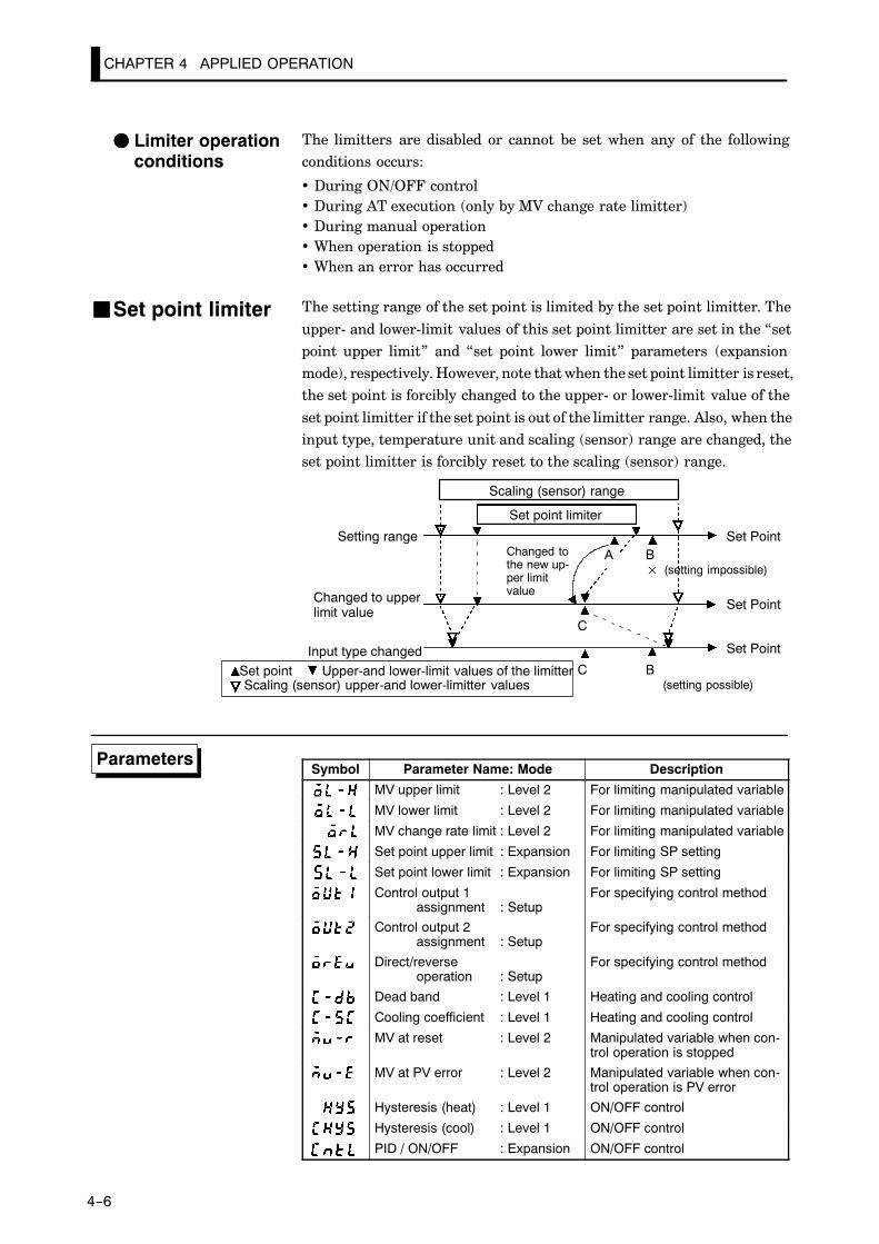
CHAPTER 4 APPLIED OPERATION
4--6
The limitters are disabled or cannot be set when any of the followingconditions occurs:
• During ON/OFF control• During AT execution (only by MV change rate limitter)• During manual operation• When operation is stopped• When an error has occurred
The setting range of the set point is limited by the set point limitter. The
upper- and lower-limit values of this set point limitter are set in the “setpoint upper limit” and “set point lower limit” parameters (expansionmode), respectively. However, note that when the set point limitter is reset,the set point is forcibly changed to the upper- or lower-limit value of the
set point limitter if the set point is out of the limitter range. Also, when theinput type, temperature unit and scaling (sensor) range are changed, theset point limitter is forcibly reset to the scaling (sensor) range.
Scaling (sensor) upper-and lower-limitter values
Changed tothe new up-per limitvalue
Scaling (sensor) range
Set Point
Set point Upper-and lower-limit values of the limitter
Set point limiter
Setting range
Changed to upperlimit value
Input type changed
Set Point
A
B×
C B
(setting impossible)
(setting possible)
C
Set Point
Symbol Parameter Name: Mode Description
MV upper limit : Level 2 For limiting manipulated variable
MV lower limit : Level 2 For limiting manipulated variable
MV change rate limit : Level 2 For limiting manipulated variable
Set point upper limit : Expansion For limiting SP setting
Set point lower limit : Expansion For limiting SP setting
Control output 1assignment : Setup
For specifying control method
Control output 2assignment : Setup
For specifying control method
Direct/reverseoperation : Setup
For specifying control method
Dead band : Level 1 Heating and cooling control
Cooling coefficient : Level 1 Heating and cooling control
MV at reset : Level 2 Manipulated variable when con-trol operation is stopped
MV at PV error : Level 2 Manipulated variable when con-trol operation is PV error
Hysteresis (heat) : Level 1 ON/OFF control
Hysteresis (cool) : Level 1 ON/OFF control
PID / ON/OFF : Expansion ON/OFF control
FF Limiter operationconditions
JJSet point limiter
Parameters
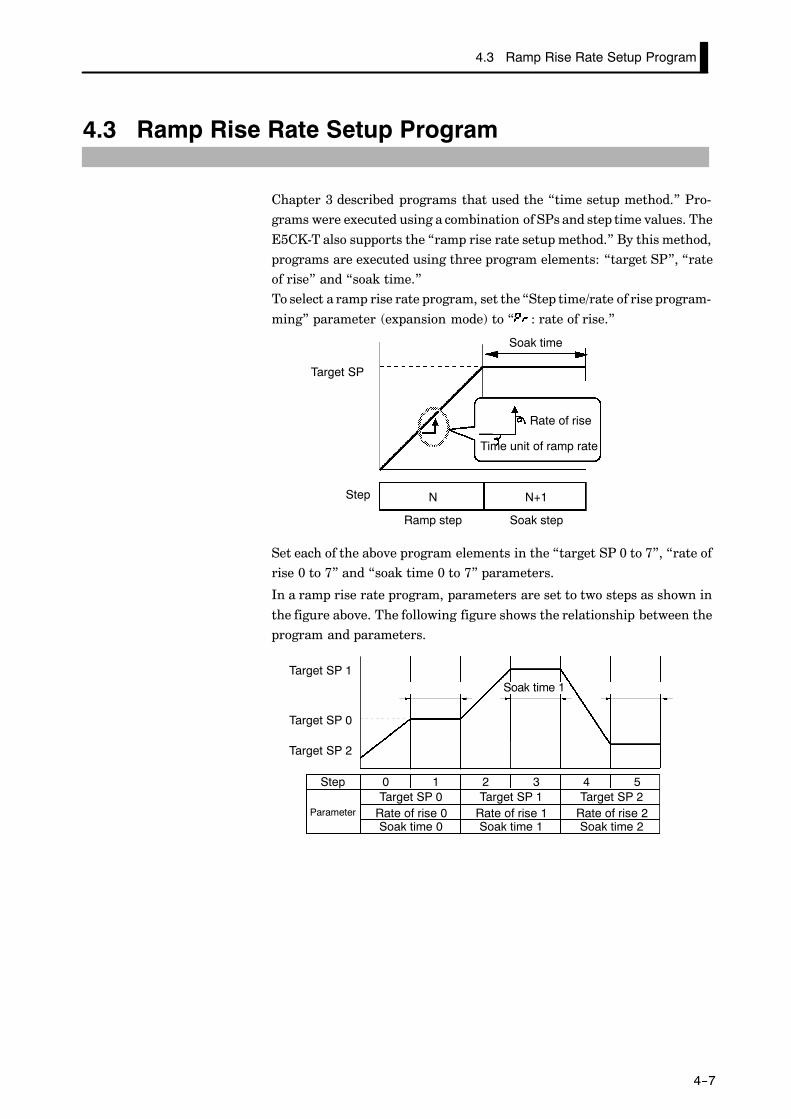
4.3 Ramp Rise Rate Setup Program
4--7
4.3 Ramp Rise Rate Setup Program
Chapter 3 described programs that used the “time setup method.” Pro-grams were executed using a combination of SPs and step time values. The
E5CK-T also supports the “ramp rise rate setup method.” By this method,programs are executed using three program elements: “target SP”, “rateof rise” and “soak time.”To select a ramp rise rate program, set the “Step time/rate of rise program-
ming” parameter (expansion mode) to “ : rate of rise.”
Target SP
Step
Ramp step Soak step
Rate of rise
Time unit of ramp rate
Soak time
N N+1
Set each of the above program elements in the “target SP 0 to 7”, “rate ofrise 0 to 7” and “soak time 0 to 7” parameters.
In a ramp rise rate program, parameters are set to two steps as shown in
the figure above. The following figure shows the relationship between theprogram and parameters.
Target SP 2
Target SP 0
Target SP 1Soak time 0 Soak time 1 Soak time 2
Step
Parameter
0 1 2 3 4 5Target SP 0 Target SP 1 Target SP 2
Rate of rise 0 Rate of rise 1 Rate of rise 2Soak time 0 Soak time 1 Soak time 2

CHAPTER 4 APPLIED OPERATION
4--8
When the number of steps is set to an odd number, the final soak time can-not be set. For example, if we set the “number of steps” parameter to “7”,the “soak time 3” parameter cannot be set even though the “target SP 3”and “rate of rise 3” parameters can be set.
Accordingly, when the number of steps are set to an even number, the finalstep is a soak step. When it is set to an odd number, the final step is a rampstep.
Number of steps = even number Number of steps = odd number
When “rate of rise 0 to 7” parameter are set to “0”, the ramp step is skipped
and the soak step appears to be continuous.
Step N is skipped.
Step
Ramp step Soak step
N N-1
Soak step
N+1
Ramp rise rate setup programs take the PV at start of program operationas the SP (PV start) when they are started.
When the rate of rise is changed midway during operation, the SP rate ofrise and the step time in the ramp cycle both change.
After change
Beforechange
Switching point
Time
Before change
After change
Step N Step N+1
Step N Step N+1
• In the above figure, increasing the rate of rise results in a shorter targetstep time. Likewise, when the SP is changed, the step time of the rampcycle also changes.
• When the soak time is changed, only the step time in the soak cyclechanges.
FF Relationship withthe number ofsteps
FFWhen the rate ofrise is set to “0”
JJRunning the ramprise rate setupprogramFF Changing
parameters

4.3 Ramp Rise Rate Setup Program
4--9
Let’s describe a typical example of a ramp rise rate setup program. In anactual program, set the parameters to match the application.
Step 0 Step 1 Step 2 Step 310
100
30 60 90 120
Target SP 0 : 100Rate of rise 0 : 3Soak time 0 : 0.30
Target SP 1 : 10Rate of rise 1 : 3Soak time 1 : 0.30
“Number of steps” = 4, “Time unit of ramp rate” = minutes, “PV start” = 10
In a program comprising four steps, steps 0 and 1 follow the settings of the
“target SP 0”, “rate of rise 0” and “soak time 0” parameters. Steps 2 and3 follow the settings of the “target SP 1”, “rate of rise 1” and “soak time1” parameters.
(1) As the program starts at PV (PV start), the program starts operationfrom “10” in this example.
(2) As the rate of rise is set to “3”, the Present SP takes 30 minutes(100-10/3=30) to reach the target SP value “100” in step 0. If the PVis “40” when the program is started, this time then becomes 20 min-utes using the same formula.
(3) In step 1, the Present SP does not change, and the step time is the val-ue set to the “soak time 0” parameter (in this example, “30 minutes”).
(4) In step2, the Present SP changes according to the value of “rate of rise
1” parameter from that of “target SP 0” parameter to that of “targetSP 1” parameter It takes 30 minutes in this example.
(5) In step 3, the Present SP does not change, and the step time is the val-ue set to the “soak time 1” parameter (in this example, “30 minutes”).
Symbol Parameter Name: Mode Description
Step time/Rate of rise programming : Expansion Ramp rise rate
: Target SP 0 to 7 : Program Ramp rise rate
: Rate of rise 0 to 7 : Program Ramp rise rate: Soak time 0 to 7 : Program Ramp rise rate
: : to
By ramp rise rate setup method, starting at input error, the program start step is t“step 1”.
Operationat Input Error
JJProgram example
FF Programstructure
FF How the programworks
Parameters

CHAPTER 4 APPLIED OPERATION
4--10
4.4 Program Operation
• Steps in currently executing programs can be forcibly stopped (Hold)and advanced (Advance).
• Hold and Advance operation is according to the following procedure:
Run in level 0 mode
Check step No.
Hold?
Hold = ON
ContinueEnd of hold?
End
Hold = OFF
Advance
Advance = ON
Continue
End of advance
End
End: To program operation
Y
Y
N
N
• Execute hold/advance operation while making sure the step No. in the“step No. monitor” parameter (level 0 mode).
• When the “hold” parameter (level 0 mode) is set to “ : ON”, step timecounting is paused (held), and the “HOLD” LED lights. [ ] and theSP appear alternately on the No.2 display when in the “PV/Present SP”parameter.
• Hold is canceled time counting is restarted by one of the following condi-tions: “hold” parameter = “ : OFF”, Run, Reset, End operation us-ing advance instruction
• Each time that “advance” parameter (level 0 mode) is set to “ : ON”,the program advances one step. With each step advance, the “Advance”parameter setting returns to “ : OFF”.
• If the advance function is executed with the program in a hold state, thehold state is continued in the next step.
JJHold/advance

4.4 Program Operation
4--11
JJPattern operation• To repeatedly execute the same pattern, set the number of times that the
pattern is to be executed in the “pattern execution count” parameter(program mode).
• The pattern execution count can be set up to 9999 (times). (Default is“0”.)
• Patterns for which the “pattern execution count” parameter is set to “0”cannot be executed.
• The count of the currently executing pattern in the program can be veri-fied in the “pattern execution count monitor” parameter (level 0 mode).“0” is indicated in this parameter when the controller of reset or in astandby state.
• To execute all preset patterns in order from pattern 0, set the “run allenable” parameter (expansion mode) to “ : ON”. (Default “ :OFF”.)
Time
Pattern 0 Pattern 1 Pattern 2
• When a power interruption occurs during run all execution, if the “op-eration at power ON” parameter (expansion mode) is set to “ : Con-tinue”, the currently executing pattern No. is held in memory. Whenpower is restored, program operation resumes from the pattern that wasbeing executed when the power was interrupted. (For details on opera-tion at power ON, see page 4-19.)
• Patterns whose “pattern execution count” is set to “0” are skipped.
Time
Pattern 0 Pattern 1 Pattern 3
“pattern execution count” of pattern 2 is set to 0
FF Repeating execu-tion of the samepattern
FF Executing allpatterns
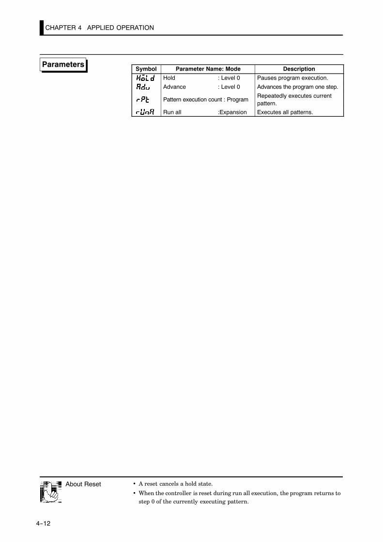
CHAPTER 4 APPLIED OPERATION
4--12
Symbol Parameter Name: Mode Description
Hold : Level 0 Pauses program execution.
Advance : Level 0 Advances the program one step.
Pattern execution count : ProgramRepeatedly executes currentpattern.
Run all :Expansion Executes all patterns.
• A reset cancels a hold state.
• When the controller is reset during run all execution, the program returns tostep 0 of the currently executing pattern.
About Reset
Parameters

You can verify the pattern elapsing time in the “pattern elapsing time” paramet(level 0 mode). During repeated execution of patterns or run all execution, the pgram is counting for each pattern.If the count exceeds the monitor range (99 hours:59 minutes or 99 minutes:59conds), “99.59” is displayed flashing.During Hold, time counting is paused.Executing Advance, the skipped step time is counted.
About PatternElapsing Time
4.5 Program output
4--13
4.5 Program output
• The E5CK-T outputs the following signals according to how far the pro-gram has elapsed:
Time signal 1/2Program endStage output
• These functions can be used only when they have been assigned as outputs.
• Two types of time signals can be set to each pattern.
Time signal output
ON time
OFF time
Time
• There are two timers for time signals: ON time timer and OFF time tim-er. These times are counted from the beginning of the step.
• Output is ON from the ON time elapsed point up to the OFF time elapsedpoint.
• Set the step at which to output the time signal in the “time signal 1/2 en-abled step” parameter (program mode). (Default is “0: step 0.”)
• Set the ON/OFF timing in the “time signal 1/2 ON time” and “time sig-nal OFF time” parameters (program mode).
• When the OFF time is set shorter than the ON time, output is ON untila reset from the ON time elapsed point onwards or at start of the nextpattern.
• Output does not turn ON when ON and OFF times are set the same.
• When step advance is executed during execution of the time signal en-abled step, the controller judges that the time equivalent to the enabledstep has elapsed. For example, in the above figure, output is ON from thestart of the following step up to the OFF time elapsed point.
JJTime signal
FF About ONconditions

CHAPTER 4 APPLIED OPERATION
4--14
JJProgram status
• One-second pulse signal is output after the final step is completed.
Final step
Program end output
Time
1s
• One-second pulse signal is output at the beginning of each step.
Stage output
Time1s
Symbol Parameter Name: Mode Description: Time signal:set step : Program Time signal
: Time signal:ON time : Program Time signal: Time signal:ON time : Program Time signal: Control output:assignment : Setup Program status: Auxiliary output:assignment : Setup Program status
: : to
FF Program end
FF Stage output
Parameters

4.6 Setting Running Conditions
4--15
4.6 Setting Running Conditions
• You can select from one of the following operations at power ON:Continue, Reset, Run, Manual
• If you select “Continue,” operation is started from the state that was ac-tive when power was interrupted.
• If you select “Reset,” the controller is reset.
• If you select “Run,” normal program operation is started.
• If you select “Manual,” the controller enters the manual mode.
• The following table shows the relationship between operation at powerON and the operation details that are stored to memory when a powerinterruption occurs.
Continue Reset Run ManualPattern No. f f f f
Step No. f - - f
Pattern elapsing time f - - f
Pattern execution count f - - f
Hold status f - - f
Auto/Manual f f f -Run/Reset f - - f
MV at reset *1 f - - f
Manual MV *2 f f f f
*1 During auto mode at power interruption
*2 During manual mode at power interruption• Set the desired operation in the “operation at power ON” parameter (ex-
pansion mode). Default is “ : Continue”.
JJOperation atpower ON

CHAPTER 4 APPLIED OPERATION
4--16
JJStarting theprogram run
• When the program is configured by the time setup method, a ramp-priority “PV start” can be selected as one of the run start conditions. Ifyou select “PV start” in the “PV start” parameter (expansion mode),program operation is started from the position of the SP that firstmatches the PV when program run is started. If the SP does not matchthe PV, the program run is started from the beginning.
SP
PV
Step 0 Step 1 Step 2 Step 3
Disabled time
Start point
Time
• After the run instruction, the controller is reset until the standby timeelapses.
• Set the standby time in the “standby time” parameter (level 2 mode)within the range 0.00 to 99.59 (hours:minutes). Defaults is “0.00”.
• After end of operation, the controller normally is reset. However, controlcan be continued on the SP of the final step by setting the “end condi-tion” parameter (expansion mode). If the “end condition” is set, the SPof the final step and [ ] appears alternately on the No.2 display.
• When the “number of steps” parameter is changed after operation hasended, the controller state does not change state. However, if controlwith respect to the SP is continued, the SP switches to the new value ofthe final step.
Symbol Parameter Name: Mode Description
Operation at power ON : Expansion Operation when power isturned ON
PV start : Expansion Start of program run
Standby time : Level 2 Start of program run
End condition : Expansion Operation end program run
FF PV start
FF Standbyoperation
JJEnd condition
Parameters

4.7 How to Use Event Input
4--17
4.7 How to Use Event Input
• When using event input, add on the input unit (E53---CKB)
• Switching by event input is not possible on the menu display.
• Switch event inputs ON and OFF while controller power is ON.
• You can choose from the following five event input functions:
Run/ResetAuto/ManualHold/Hold cancelAdvancePattern select
• Event input ON/OFF judgment is carried out on inputs of 200 ms mini-mum.
• When event inputs are used as program advance input, the program stepis advanced at the rising (OFF ON) edge of the input signal. Whenevent inputs are used as run/reset input, program operation is stopped(reset) at the rising (OFF ON) edge of the input signal, and programoperation is started (run) at the falling (ON OFF) edge. Other signalsare accepted at all times.
• Set event input assignments in the “event input assignment 1” parame-ter (option mode).
• The following table shows the relationship between the settings andfunctions of the “event input assignment 1” parameter.
Setting Function
Event input disabled
OFF ON: Reset /ON OFF: Run
ON: Manual /OFF: Auto
ON: Hold /OFF: Hold cancel
Execute at OFF ON
OFF : pattern 0 / ON: pattern 1 (*1)
OFF: pattern 0 / ON: pattern 2 (*2)*1 Enabled when the “number of patterns” parameter is set to “2” or more
*2 Enabled when the “number of patterns” parameter is set to “3” or more
JJ Inputassignments

CHAPTER 4 APPLIED OPERATION
4--18
• There is no order of priority in event input, key operations and commu-nications command setup. However, remote/local, auto/manual, hold/hold cancel or pattern selection be set to either of ON or OFF. So, param-eters will always follow event input even if you try to switch settings bykey operation and communications commands.
• Program operation is stopped (reset) at the rising edge (OFF ON) ofthe event input signal, and the RST LED lights. Program operation isstarted (run) at the falling edge (ON OFF) of the event input signal.
• When event input is set to “ON”, the controller is switched to manualoperation, and the “MANU” LED lights.
• This function is enabled only during program operation.
• The program is paused (Hold) when the event input is ON, and the“HOLD” LED lights. Holds continue until the state of the event inputchanges to OFF.
• This function is enabled only during program operation.
• Program steps are advanced at the rising (OFF ON) edge of the eventinput signal. Accordingly, be sure to set event input OFF before you usethis function.
• This function is enabled only when the program is reset.
• Patterns are selected by pattern select input. The number of patternsthat can be selected are dependent on the value set to the “number of pat-terns” parameter. For example, when this parameter is set to “4”, youcan select from patterns 0 or 2.
Symbol Parameter Name: Mode Description
Event input assignments Option Event input functions
JJDetaileddescription ofinput functions
FF Run/Reset
Reset Run
FF Auto/Manual
FF Hold/Hold cancel
FF Advance
Advance
FF Pattern select
Parameters
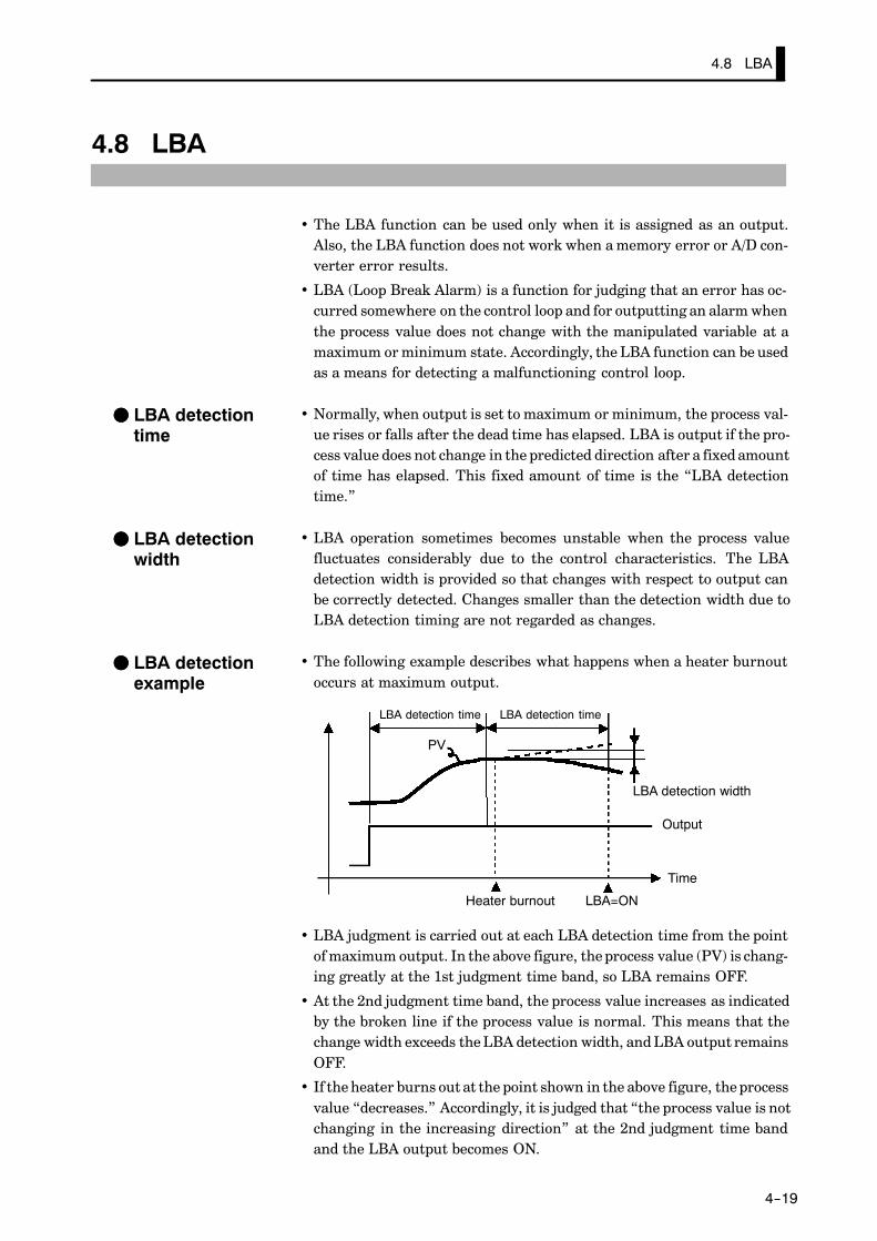
4.8 LBA
4--19
4.8 LBA
• The LBA function can be used only when it is assigned as an output.Also, the LBA function does not work when a memory error or A/D con-verter error results.
• LBA (Loop Break Alarm) is a function for judging that an error has oc-curred somewhere on the control loop and for outputting an alarm whenthe process value does not change with the manipulated variable at amaximum or minimum state. Accordingly, the LBA function can be usedas a means for detecting a malfunctioning control loop.
• Normally, when output is set to maximum or minimum, the process val-ue rises or falls after the dead time has elapsed. LBA is output if the pro-cess value does not change in the predicted direction after a fixed amountof time has elapsed. This fixed amount of time is the “LBA detectiontime.”
• LBA operation sometimes becomes unstable when the process valuefluctuates considerably due to the control characteristics. The LBAdetection width is provided so that changes with respect to output canbe correctly detected. Changes smaller than the detection width due toLBA detection timing are not regarded as changes.
• The following example describes what happens when a heater burnoutoccurs at maximum output.
PV
LBA=ON
LBA detection time
LBA detection width
Output
Time
Heater burnout
LBA detection time
• LBA judgment is carried out at each LBA detection time from the pointof maximum output. In the above figure, the process value (PV) is chang-ing greatly at the 1st judgment time band, so LBA remains OFF.
• At the 2nd judgment time band, the process value increases as indicatedby the broken line if the process value is normal. This means that thechange width exceeds the LBA detection width, and LBA output remainsOFF.
• If the heater burns out at the point shown in the above figure, the processvalue “decreases.” Accordingly, it is judged that “the process value is notchanging in the increasing direction” at the 2nd judgment time bandand the LBA output becomes ON.
FF LBA detectiontime
FF LBA detectionwidth
FF LBA detectionexample

CHAPTER 4 APPLIED OPERATION
4--20
• The LBA detection time is automatically set by auto-tuning (except inheating and cooling control).
• If the optimum LBA detection time cannot be obtained by auto-tuning,set the time in the “LBA detection time” parameter (level 2 mode).
• Calculate the LBA detection time as follows:
(1) Set output to maximum.
(2) Measure the time it takes for the input change width to reach the LBAdetection width (factory setting: 0.2% FS).
PV
0.2%FS
Measurement time Tm
LBA detection time = Tm x 2
Output
Time
(3) Take a value twice that of the measurement time as the LBA detectiontime.
Symbol Parameter Name: Mode Description
AT execute/Cancel : Level 1 For automatic setting of LBAdetection time
LBA detection time : Level 2 For setting LBA detection time
LBA detection width : Expansion For changing LBA detectionwidth
FF Setting the LBAdetection time
FF Determining theLBA detectiontime
Parameters

4.9 How to Use Transfer Output
4--21
4.9 How to Use Transfer Output
• When using transfer output, add on the communications unit(E53-CKF).
• You can select the following four data items in the “transfer output type”parameter (option mode) as the transfer outputs:
Present SP (default), Process value, Manipulated variable (heat),Manipulated variable (cool).
• If the output assignment is changed when either the “manipulated vari-able (heat)” or “manipulated variable (cool)” parameter is selected, thefactory setting “set point” is returned to.
• These transfer outputs can be scaled according to the settings of the“transfer output upper limit” and “transfer output lower limit” param-eters before output. Setting of an upper limit value smaller than the low-er limit value is allowed, so reverse scaling can also be carried out. Also,the scale can be enlarged by the upper- and lower-limit width specifiedfor each data item. The following example shows scaling of the heatingside manipulated variable.
(mA)
20
4
20
4
0100
(mA)Transfer output Transfer output
Reverse scaling Enlarged scale
Transfer outputupper limit: 0
Transferoutput lowerlimit: 100
Manipu-latedvariable(%)
Transferoutput lowerlimit: 10
Transferoutput upperlimit: 80
Manipulatedvariable (%)
Symbol Parameter Name: Mode Description
Transfer output type : Option Transfer output designation
Transfer output upper limit : Option Transfer output scaling
Transfer output lower limit : Option Transfer output scaling
FF Transfer outputtype
FF Transfer outputscaling
Parameters

CHAPTER 5 PARAMETERS
5--1
CHAPTER 5PARAMETERS
This chapter describes the parameters of the E5CK-T.Use this chapter as a reference guide.
CHAPTER5
Conventions Used in this Chapter 5-2. . . . . . . . . . . .
Protect Mode 5-3. . . . . . . . . . . . . . . . . . . . . . . . . . . . . . .
Manual Mode 5-5. . . . . . . . . . . . . . . . . . . . . . . . . . . . . .
Level 0 Mode 5-6. . . . . . . . . . . . . . . . . . . . . . . . . . . . . . .
Program Mode 5-11. . . . . . . . . . . . . . . . . . . . . . . . . . . . .
Level 1 Mode 5-17. . . . . . . . . . . . . . . . . . . . . . . . . . . . . . .
Level 2 Mode 5-24. . . . . . . . . . . . . . . . . . . . . . . . . . . . . . .
Setup Mode 5-28. . . . . . . . . . . . . . . . . . . . . . . . . . . . . . . .
Expansion Mode 5-36. . . . . . . . . . . . . . . . . . . . . . . . . . . .
Option Mode 5-44. . . . . . . . . . . . . . . . . . . . . . . . . . . . . . .
Calibration Mode 5-48. . . . . . . . . . . . . . . . . . . . . . . . . . .

5--2
JJThe meaning of icons used in this chapter
Describes the functions of the parameter.
Describes the range and defaults of the parameter setting.
Used for monitor-dedicated parameters.Describes the range of the monitor values.
Describes a procedure using parameters in operating instructions.
Describes related parameters and items.
Describes models of the E5AK-T or optional units that support the parameter beingdescribed.
JJAbout parameter displayOn the E5CK-T controller, only parameters that can be used are displayed. These parameters aredisplayed only when the “Conditions of Use” on the right of the parameter heading are satisfied.However, note that the settings of protected parameters are still valid, and are not displayedregardless of the conditions of use.
Conditions of UseThe controller mustbe in operation.
AT Execute/cancel
JJAbout the Order in Which Parameters Described in This ChapterParameters are described mode by modeThe first page of each mode lists the parameters available in that mode. The parameter namesin these contents are listed in the order that they are displayed on the controller.
Conventions Used in this Chapter
Function
Comment
Monitor
Exampleof use
See
Model

5--3
• The protect function restricts key use to prevent unwanted key operation. Before
changing parameters in this mode, first make sure that protecting the keys will notcause any problems in operation.
• To select this mode, press the RUN/RST and keys simultaneously for 1 second
minimum. To exit this mode, press the RUN/RST and keys simultaneously againfor 1 second minimum.
• The following table shows the parameters supported in this mode and the page wherethe parameter is described.
Symbol Parameter Name PageSecurity 5-3Key protect 5-4
Security
• This parameter specifies which parameters are protected. Note that the protect mode
and manual mode cannot be protected.
• Only the modes indicated by the “F” mark in the table below can be selected on themenu display. For example, when this parameter is set to “3”, only levels 0 and 1 andthe program mode can be selected.
ModeSetting value
Mode0 1 2 3 4 5 6
Calibration F
Option F F
Expansion F F
Setup F F
Level 2 F F F
Level 1 F F F F
Program F F F F F
Level 0 F F F F F F *1
*1 The “PV/Present SP” parameter is only displayed.
• When this parameter is set to “0”, the protection function is disabled.
• When this parameter is set to “5”, only the parameters in the level 0 mode can be used,and the menu display is not selected.
• When this parameter is set to “6”, “PV/Present SP” parameter can only be displayed.(The set point cannot be changed.)
• Default is “1”. (Only the calibration mode is protected.)
F Related description3.6 Protect Mode (page 3-19)
Protect Mode
Function
Comment
See

5--4
Key protect
• Disables key operation of the RUN/RESET or AUTO/MANUAL. For example, ifAUTO/MANUAL key operation is disabled (by simultaneously pressing the and
keys) in the “key protect” parameter (protect mode) during automatic operation,manual operation is no longer possible.
• The following table shows the relationship between set values and protected keys.
Set value Description
1 No keys are protected.
2 AUTO/MANUAL key operation cannot be selected.
3 “RUN/RST” key cannot be selected.RUN/RST
4 Both the AUTO/MANUAL and RUN/RESET key operationscannot be selected.
• Default is “0” (all keys can be operated).
F Related description3.6 Protect Mode (page 3-19)
Protect Mode
Function
Comment
See

5--5
• In this mode, manual operation is possible, and the “MANU” LED lights.
• When this mode is selected, the manipulated variable that was active immediately
before the mode was switched to is output. To change the manipulated variable, usethe or keys. If this mode is switched to during auto-tuning, auto-tuning iscanceled.
• To select this mode when in the level 0 to 2 modes, press the and keys simul-
taneously for 1 second minimum. To exit this mode, press the and keyssimultaneously again for 1 second minimum. The mode changes to the level 0 mode.
• “Manual MV” is the only parameter available in this mode.
Manual MV
• Sets the manipulated variable for manual operation. When you press the orkeys, the manipulated variable is changed.
• The process value is displayed on the No.1 display and the manipulated variable isdisplayed on the No.2 display.
• The manual MV is held when the power is interrupted.
Control Method Setting Range Unit DefaultStandard -5.0 to 105.0 % 0.0Heating and cooling -105.0 to 105.0 % 0.0
F Related description3.8 Adjusting Control Operation/Manual operation (page 3-22)
Manual Mode
Function
Comment
See

5--6
• The parameters in this mode can be used only when the “security” parameter (pro-
tect mode) is set to “0” to “5”. Only the “PV/Present SP” parameter can be used whenthe “security” parameter is set to “6”.
• The parameters in this mode comprise step operation parameters and parametersrequired for monitoring program operating states.
• To select this mode, press the key for 1 second minimum. The display changesto the menu display. If you select [ ] then press the key for 1 second mini-mum, the controller enters the level 0 mode.
• To select parameters in this mode, press the key. To change parameter settings,use the or keys.
• The following table shows the parameters supported in the level 0 mode and the page
where the parameter is described.
Symbol Parameter Name Page
PV/Present SP 5-6
Pattern No. 5-7
Step No. monitor 5-7
Hold 5-8
Advance 5-8
Standby time monitor 5-9
Pattern elapsing time 5-9
Pattern execution count monitor 5-9
MV monitor (heat) 5-10
MV monitor (cool) 5-10
PV/Present SP
• The process value is displayed on the No.1 display, and the Present SP is displayedon the No.2 display.
• The decimal point position is dependent on the selected sensor during temperaturesinput and on the results of scaling during analog input.
Monitor Range UnitProcess Value Scaling lower limit -10%FS to scaling upper limit +10%FS EU
Present SP Set point lower limit to set point upper limit EU
• During temperature input, the range of the currently selected sensor is taken as thePV monitor range.
F Related parameters“Input type” “Scaling upper limit” “Scaling lower limit” “Decimal point” (setup mode)“Set point upper limit” “Set point lower limit” (expansion mode)
Level 0 Mode
Function
Monitor
See

5--7
Pattern No. Conditions of UseThe “number of patterns” parameter mustbe set to a value greater than “2”.
• This parameter can be set only when the controller is reset.
• Displays the execution pattern during program operation, and the set pattern afterthe controller is reset.
• This parameter can also be used in the program mode.
Setting Range Unit Default0 to number of patterns -1 None 0
F Related description3.5 Setting Patterns (page 3-14)
F Related parameters
All parameters in the program mode“Number of patterns” (expansion mode)
Step No. monitor
• Monitors the current step No. (This parameter is reset to “0” when the controller isreset.)
Monitor Range Unit0 to Number of steps-1 None
F Related description4.4 Program Operation (page 4-13)
F Related parameters
“Hold” “Advance” (level 0 mode)
Level 0 Mode
Function
Comment
See
Function
Monitor
See

5--8
Hold
• This parameter can only be used for monitoring when the controller is reset.
• Pauses (holds) or cancels program operation.
• When the event input to which “hold/hold cancel” is assigned is ON, [ ] (hold) isdisplayed, and when OFF [ ] (hold cancel) is displayed.
• In addition to the setting of this parameter, hold is canceled by the following condi-tions:
Setting Range DefaultOFF : Hold cancel / ON: Hold
F Related description4.4 Program Operation (page 4-13)4.8 How to Use Event Input (page 4-17)
F Related parameters“Event input assignment 1” (option mode)
Advance
• This parameter can only be used for monitoring when the controller is reset.
• Forcibly advances program operation by one step.
• When the event input to which “hold/hold cancel” is assigned is ON, [ ] (advance)is displayed.
• Selecting this parameter, it is set to [ ] (OFF).
• When [ ] (ON) is selected, program operation is advanced by one step.
• After program exection is completed, the setting automatically returns to [ ].
• Hold is also continued after the program step is advanced when the program isexecuted in a hold state.
F Related description4.4 Program Operation (page 4-13)4.7 How to Use Event Input (page 4-17)
F Related parameters
“Event input assignment 1” (option mode)
Level 0 Mode
Function
Comment
See
Function
Exampleof use
See

5--9
Standby time monitor Conditions of UseThe controller must be in a standby state.
• Displays the remaining standby time. (This time is not displayed when the controller
is reset.)
Monitor Range Unit0.00 to 99.59 Hour, minute
F Related description4.6 Setting Running Conditions (page 4-19)
F Related parameter“Standby time” (level 2 mode)
Pattern elapsing time
• Displays the time that has elapsed since the start of the pattern. When a pattern isrepeatedly executed or all patterns are executed, the time counting restarts at the top
of each pattern.
Monitor Range Unit0.00 to 99.59 Program time unit
When the time exceeds “99.59”, “99.59” blinks on the display.
Pattern execution count monitor
• Displays the number of times that the current pattern has been executed. “0” is dis-played when the controller is reset or when the controller is in a standby state.
Monitor Range Unit0 to pattern execution count Times
F Related parameter“Pattern execution count” (program mode)
Level 0 Mode
Function
Monitor
See
Function
Monitor
Function
Monitor
See

5--10
MV monitor (heat)
MV monitor (cool)
Conditions of UseThe control must be standard control orheating and cooling control.
• This parameter cannot be set.• Monitors the manipulated variable on the heating or cooling side.
• The manipulated variable in a standard control system is monitored in the “MV mon-itor (heat)” parameter.
• The “MV monitor (cool)” parameter can be used only during heating and cooling con-trol.
• MV monitor (heat)
Control Monitor Range UnitStandard -5.0 to 105.0 %Heating and cooling 0.0 to 105.0 %
• MV monitor (cool)
Control Monitor Range UnitHeating and cooling 0.0 to 105.0 %
Level 0 Mode
Function
Monitor
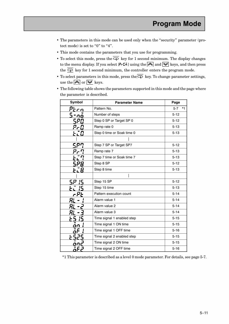
5--11
• The parameters in this mode can be used only when the “security” parameter (pro-tect mode) is set to “0” to “4”.
• This mode contains the parameters that you use for programming.
• To select this mode, press the key for 1 second minimum. The display changesto the menu display. If you select [ ] using the and keys, and then pressthe key for 1 second minimum, the controller enters the program mode.
• To select parameters in this mode, press the key. To change parameter settings,use the or keys.
• The following table shows the parameters supported in this mode and the page where
the parameter is described.
Symbol Parameter Name Page
Pattern No. 5-7 *1
Number of steps 5-12
Step 0 SP or Target SP 0 5-12
Ramp rate 0 5-13
Step 0 time or Soak time 0 5-13
| |
Step 7 SP or Target SP7 5-12
Ramp rate 7 5-13
Step 7 time or Soak time 7 5-13
Step 8 SP 5-12
Step 8 time 5-13
| |
Step 15 SP 5-12
Step 15 time 5-13
Pattern execution count 5-14
Alarm value 1 5-14
Alarm value 2 5-14
Alarm value 3 5-14
Time signal 1 enabled step 5-15
Time signal 1 ON time 5-15
Time signal 1 OFF time 5-16
Time signal 2 enabled step 5-15
Time signal 2 ON time 5-15
Time signal 2 OFF time 5-16
*1 This parameter is described as a level 0 mode parameter. For details, see page 5-7.
Program Mode

5--12
Number of steps
• Specifies the number of steps in the current pattern.
Setting Range Unit Default1 to 16 None 8
F Related description3.5 Setting Patterns (page 3-14)
F Related parameterAll parameters in the program mode
Step 0 time (Step time)Target SP 0 (Rate of rise programming)
toStep 7 SP (Step time)Target SP 7 (Rate of rise programming)
Step 8 SP (Step time)
Step 15 SP (Step time)
• Sets the SP of steps 0 to 15 when the step time is set.• Sets target SP 0 to 7 when the rate of rise programming is set.
• During temperature input, the decimal point position is dependent on the currently
selected sensor, and during analog input on the results of scaling.
Setting Range Unit DefaultSP lower limit to SP upper limit EU 0
F Related description3.5 Setting Patterns (page 3-14)4.3 Ramp Rise Rate Setup Program (page 4-9)
F Related parametersAll parameters in the program mode“Input type” “Scaling upper limit” “Scaling lower limit” “Decimal point” (setup mode)“Step time/Rate of rise programming” (expansion mode)
Program Mode
Function
Comment
See
Conditions of UseWithin the number of steps.
to
Function
Comment
See

5--13
Ramp rate 0
to
Ramp rate 7
Conditions of UseWithin the number of steps only in the rateof rise programing.
• Sets the degree of change per time unit of ramp rate in the step time ramp step.
Setting Range Unit Default0 to 9999 EU/Time unit of ramp rate 0
0: The ramp step is skipped.
F Related description4.3 Ramp Rise Rate Setup Program (page 4-9)
F Related parametersAll parameters in the program mode“Step time/Rate of rise programming” “Time unit of ramp rate” (expansion mode)
Step 0 time (Step time)Soak time 0 (Rate of rise programming)
toStep 7 time (Step time)Soak time 7 (Rate of rise programming)
Step 8 time (Step time)
Step 15 time (Step time)
• Sets the time of steps 0 to 15 when the step time is set.• Sets soak steps 0 to 7 when the rate of rise programming is set.
Setting Range Unit Default0.00 to 99.59 Program time unit 0.00
F Related description3.5 Setting Patterns (page 3-14)4.3 Ramp Rise Rate Setup Program (page 4-9)
F Related parametersAll parameters in the program mode“Step time/Rate of rise programming” “Program time unit” “Time unit of ramprate” (expansion mode)
Program Mode
Function
Comment
See
Conditions of UseWithin the number of steps.
to
Function
Comment
See

5--14
Pattern execution count
• Executes the current pattern for the preset number of times.• The count during pattern execution can be monitored in the “pattern execution
count monitor” (level 0 mode).
Setting Range Unit Default0 to 9999 Time 1
0: The pattern is not executed
F Related description4.4 Program Operation/Pattern operation (page 4-13)
F Related parametersAll parameters in the program mode
Alarm value 1
Alarm value 2
Alarm value 3
Conditions of UseAlarms must be assigned as outputs. Forexample, if alarm outputs 1 and 2 only areassigned as outputs, the “alarm value 3”parameter cannot be used.
• This parameter is used for monitoring or setting the alarm values of alarm outputs1 to 3.
• During temperature input, the decimal point position is dependent on the currentlyselected sensor, and during analog input on the results of scaling.
Setting Range Unit Default-1999 to 9999 EU 0
F Related description3.4Setting Alarm Type (page 3-10)3.5Setting Patterns/Alarm value (page 3-16)
F Related parameters“Input type” “Scaling upper limit” “Scaling lower limit” “Decimal point” “Controloutput 1 assignment” “Control output 2 assignment” “Auxiliary output 1 assign-ment” “Alarm 1 type” “Alarm 2 type” “Alarm 3 type” “Alarm 1 open in alarm” “Alarm2 open in alarm” “Alarm 3 open in alarm” (setup mode)“Alarm 1 hysteresis” “Alarm 2 hysteresis” “Alarm 3 hysteresis” (level 2 mode)
Program Mode
Function
Comment
See
Function
Comment
See

5--15
Time signal 1 enabledstep
Time signal 2 enabledstep
Conditions of UseEach of the time signals must be assignedas outputs.
• Sets the step in which the time signal is used.
Setting Range Unit Default0 to 15 None 0
F Related description4.5 Program output (page 4-17)
F Related parameters“Time signal 1 ON time” “Time signal 1 OFF time” “Time signal 2 ON time” “Timesignal 2 OFF time” (program mode)
Time signal 1 ON time
Time signal 2 ON time
Conditions of UseEach of the time signals must be assignedas outputs.
• Sets the ON time of the time signal.
Setting Range Unit Default0.00 to 99.59 Program time unit 0.00
F Related description4.5 Program Output (page 4-17)
F Related parameters“Time signal 1 enabled step” “Time signal 2 enabled step” “Time signal 1 OFF time”“Time signal 2 OFF time” (program mode)“Program time unit” (expansion mode)
Program Mode
Function
Comment
See
Function
Comment
See

5--16
Time signal 1 OFF time
Time signal 2 OFF time
Conditions of UseEach of the time signals must be assignedas outputs.
• Sets the OFF time of the time signal.
Setting Range Unit Default0.00 to 99.59 Program time unit 0.00
F Related description4.5 Program output (page 4-17)
F Related parameters“Time signal 1 enabled step” “Time signal 2 enabled step” “Time signal 1 ON time”“Time signal 2 ON time” (program mode)“Program time unit” (expansion mode)
Program Mode
Function
Comment
See

5--17
• The parameters in this mode can be used only when the “security” parameter (pro-tect mode) is set to “0” to “3”.
• This mode contains the main parameters for adjusting control, such as executing AT(auto-tuning), setting the control period, setting PID parameters.
• To select this mode, press the key for 1 second minimum. The display changesto the menu display. If you select [ ] then press the key for 1 second mini-
mum, the controller enters the level 1 mode.
• To select parameters in this mode, press the key. To change parameter settings,use the or keys.
• The following table shows the parameters supported in this mode and the page wherethe parameter is described.
Symbol Parameter Name Page
AT Execute/Cancel 5-18
Proportional band 5-18
Integral time 5-18
Derivative time 5-18
Cooling coefficient 5-19
Dead band 5-19
Manual reset value 5-20
Hysteresis (heat) 5-21
Hysteresis (cool) 5-21
Control period (heat) 5-22
Control period (cool) 5-22
Level 1 Mode

5--18
AT Execute/Cancel Conditions of UseThe controller must be in operation, andcontrol must be advanced PID control.
• Selects the limit cycle of MV change width (40% or 100%) for execution. After ATexecution, the “PID” and the “LBA detection time” (Loop Break Alarm) parametersare automatically set.
• During heating and cooling control, only 100%AT can be executed.
• To execute 40%AT, select [ ], and to execute 100%AT, select [ ]. During execu-tion of auto-tuning, the AT LED flashes. However, note that during heating and cool-ing control, [ ] is not displayed.
• When AT execution ends, the parameter setting automatically returns to [ ].
F Related description3.8 Adjusting Control Operation/AT (page 3-25)
F Related parameters“Proportional band” “Integral time” “Derivative time” (level 1 mode)“LBA detection mode” (level 2 mode)
Proportional band
Integral time
Derivative time
Conditions of UseThe control must be advanced PID con-trol.
• Sets the PID parameters. Note that PID is automatically set when AT is executed.
Parameter Setting Range Unit DefaultProportional band 0.1 to 999.9 %FS 10.0
Integral time 0 to 3999 *1 Second 233Derivative time 0 to 39999 Second 40
F Related parameter“AT Execute/Cancel” (level 1 mode)
Level 1 Mode
Function
Exampleof use
See
Function
Comment
See

5--19
Cooling coefficient Conditions of UseThe control must be either heating andcooling control, or advanced PID control.
• In heating and cooling control, P at the cooling side is calculated by the following for-mula:
Cooling side P = Cooling coefficient x P
Setting Range Unit Default0.01 to 99.99 None 1.00
F Related description4.1 Selecting the Control Method/Heating and cooling control (page 4-2)
F Related parameter“Proportional band” (level 1 mode)
Dead band Conditions of UseThe control system must be heating andcooling control.
• Sets the output dead band width in a heating and cooling control system. A negativesetting sets an overlap band.
Setting Range Unit Default-19.99 to 99.99 %FS 0.00
F Related description4.1 Selecting the Control Method/Heating and cooling control (page 4-2)
Level 1 Mode
Function
Comment
See
Function
Comment
See
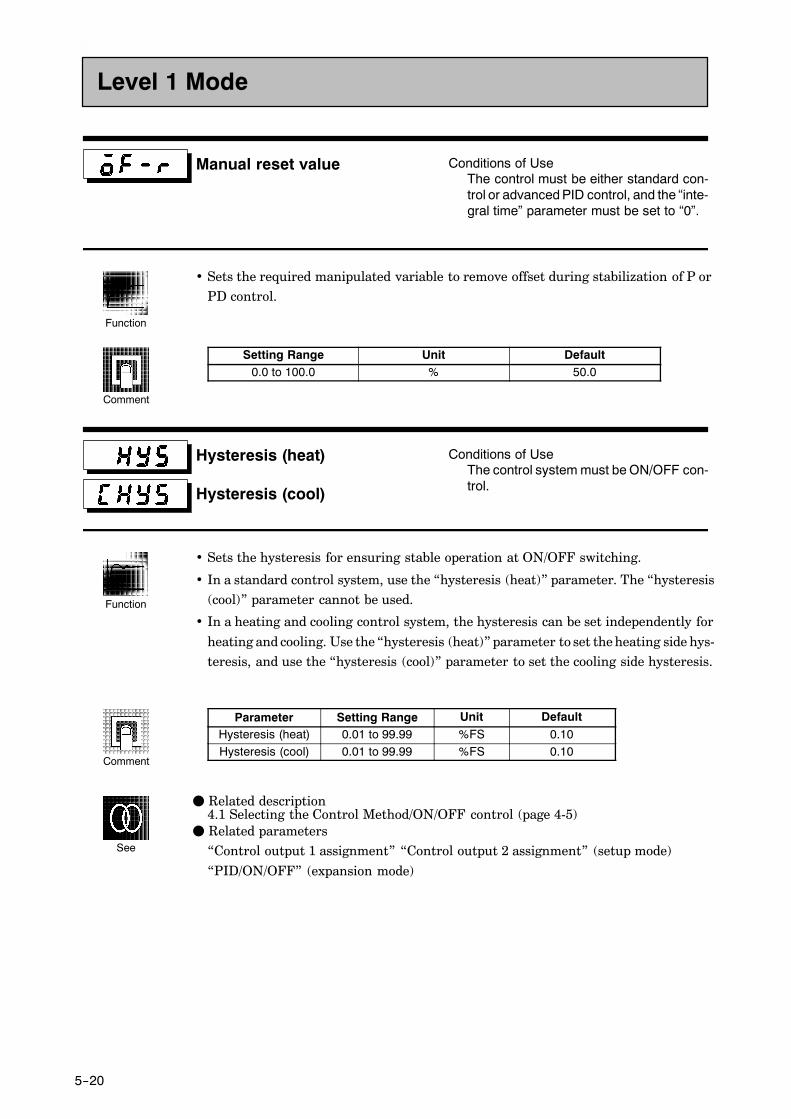
5--20
Manual reset value Conditions of UseThe control must be either standard con-trol or advanced PID control, and the “inte-gral time” parameter must be set to “0”.
• Sets the required manipulated variable to remove offset during stabilization of P orPD control.
Setting Range Unit Default0.0 to 100.0 % 50.0
Hysteresis (heat)
Hysteresis (cool)
Conditions of UseThe control system must be ON/OFF con-trol.
• Sets the hysteresis for ensuring stable operation at ON/OFF switching.
• In a standard control system, use the “hysteresis (heat)” parameter. The “hysteresis(cool)” parameter cannot be used.
• In a heating and cooling control system, the hysteresis can be set independently for
heating and cooling. Use the “hysteresis (heat)” parameter to set the heating side hys-teresis, and use the “hysteresis (cool)” parameter to set the cooling side hysteresis.
Parameter Setting Range Unit DefaultHysteresis (heat) 0.01 to 99.99 %FS 0.10Hysteresis (cool) 0.01 to 99.99 %FS 0.10
F Related description4.1 Selecting the Control Method/ON/OFF control (page 4-5)
F Related parameters“Control output 1 assignment” “Control output 2 assignment” (setup mode)
“PID/ON/OFF” (expansion mode)
Level 1 Mode
Function
Comment
Function
Comment
See

5--21
Control period (heat)
Control period (cool)
Conditions of UseRelay, SSR or voltage output must set asthe outputs, and the control must be set toadvanced PID control, standard control orheating and cooling control.
• Sets the pulse output period. Set the control period taking the control characteristicsand life expectancy of the controller into consideration.
• In a standard control system, use the “control period (heat)” parameter. The “controlperiod (cool)” parameter cannot be used.
• In a heating and cooling control system, the control period can be set independentlyfor heating and cooling. Use the “control period (heat)” parameter to set the heatingside control period, and use the “control period (cool)” parameter to set the cooling
side control period.
Parameter Setting Range Unit DefaultControl period (heat) 1 to 99 Second 20Control period (cool) 1 to 99 Second 20
F Related description3.3 Setting Output Specifications (page 3-7)
F Related parameters“Control output 1 assignment” “Control output 2 assignment” (setup mode)
Level 1 Mode
Function
Comment
See

5--22
• The parameters in this mode can be used only when the “security” parameter (pro-tect mode) is set to “0” to “2”.
• This mode contains the auxiliary parameters for adjusting control. These parame-ters include parameters for limiting the manipulated variable, parameters forswitching between remote and local operation, and parameters for setting the LBA(Loop Break Alarm), alarm hysteresis, and input digital filter values.
• To select this mode, press the key for 1 second minimum. The display changesto the menu display. If you select [ ] pressing the and keys, and thenpress the key for 1 second minimum, the controller enters the level 2 mode.
• To select parameters in this mode, press the key. To change parameter settings,use the or keys.
• The following table shows the parameters supported in this mode and the page wherethe parameter is described.
Symbol Parameter Name Page
Remote/Local 5-25
Standby time 5-25
LBA detection time 5-26
MV at reset 5-26
MV at PV error 5-27
MV upper limit 5-27
MV lower limit 5-27
MV change rate limit 5-27
Input digital filter 5-28
Alarm 1 hysteresis 5-29
Alarm 2 hysteresis 5-29
Alarm 3 hysteresis 5-29
Input shift upper limit 5-29
Input shift lower limit 5-29
Level 2 Mode
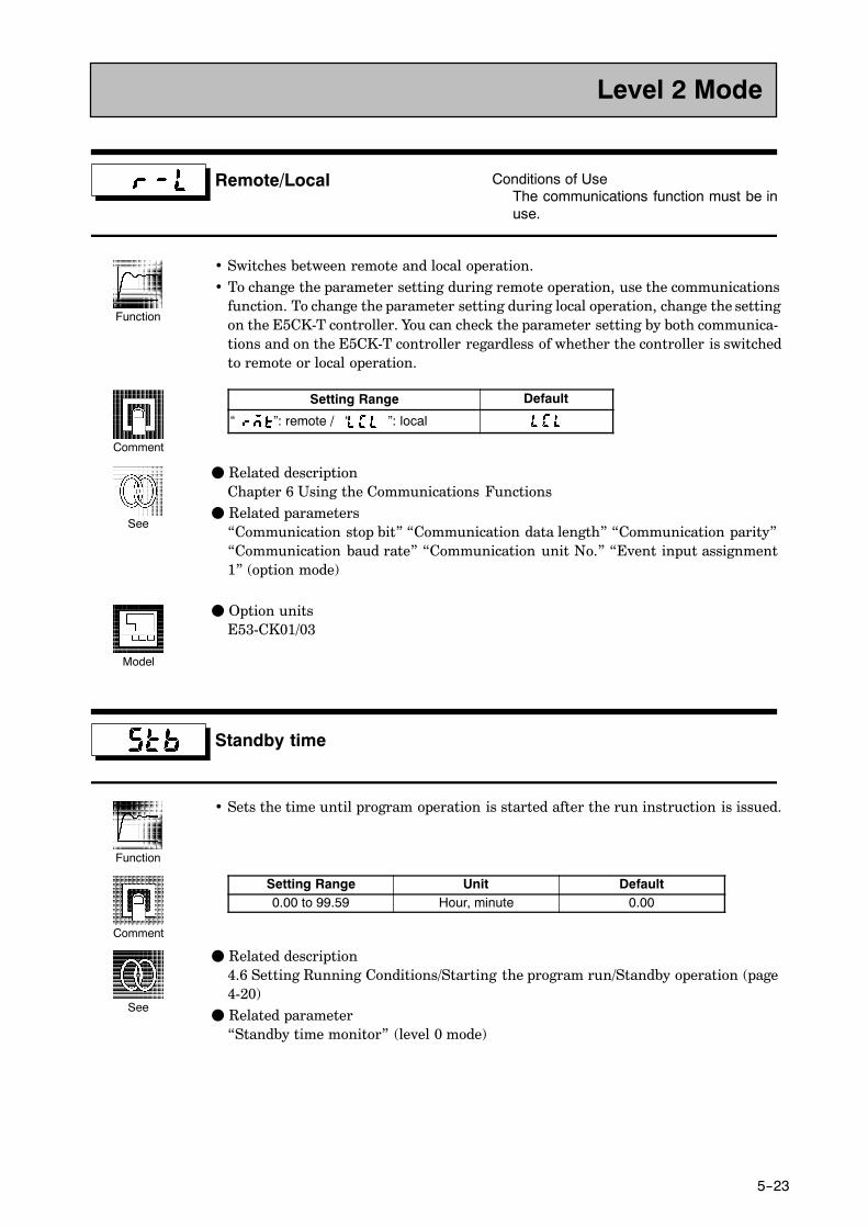
5--23
Remote/Local Conditions of UseThe communications function must be inuse.
• Switches between remote and local operation.• To change the parameter setting during remote operation, use the communications
function. To change the parameter setting during local operation, change the settingon the E5CK-T controller. You can check the parameter setting by both communica-tions and on the E5CK-T controller regardless of whether the controller is switchedto remote or local operation.
Setting Range Default
“ ”: remote / “ ”: local
F Related descriptionChapter 6 Using the Communications Functions
F Related parameters“Communication stop bit” “Communication data length” “Communication parity”“Communication baud rate” “Communication unit No.” “Event input assignment1” (option mode)
F Option unitsE53-CK01/03
Standby time
• Sets the time until program operation is started after the run instruction is issued.
Setting Range Unit Default0.00 to 99.59 Hour, minute 0.00
F Related description4.6 Setting Running Conditions/Starting the program run/Standby operation (page4-20)
F Related parameter“Standby time monitor” (level 0 mode)
Level 2 Mode
Function
Comment
See
Model
Function
Comment
See

5--24
LBA detection time Conditions of UseThe LBA (Loop Break Alarm) functionmust be assigned as an output.
• This parameter is automatically set by AT execution.• The LBA is output if the change width of the process value falls below 0.2 %full-scale
of the time preset to this parameter when the manipulated variable is set in the “MVupper limit” or “MV lower limit” parameters.
• The LBA function is disabled when this parameter is set to “0”.
Setting Range Unit Default0 to 9999 Second 0
F Related description4.8 LBA (page 4-20)8.3 How to Use Error Output (page 8-5)
F Related parameters“AT Execute/Cancel” (level 1 mode)“Control output 1 assignment” “Control output 2 assignment” “Auxiliary output 1assignment” (setup mode)
MV at reset
MV at PV error
Conditions of UseAdvanced PID control.
• The “MV at reset” parameter sets the manipulated variable when operation hasstopped.
• The “MV at PV error” parameter sets the manipulated variable when an input erroroccurs.
Control Method Setting Range Unit DefaultStandard -5.0 to 105.0 % 0.0Heating and cooling -105.0 to 105.0 % 0.0
The manipulated variable at the cooling side during heating and cooling control isexpressed as a negative value.
F Related descriptionMV at reset : 3.7 Starting and Stopping Operation (page 3-21)MV at PV error : 8.2 How to Use the Error Display (page 8-3)
Level 2 Mode
Function
Comment
See
Function
Comment
See

5--25
MV upper limit
MV lower limit
MV change rate limit
Conditions of UseThe control must be advanced PID con-trol.
• The “MV upper limit” and “MV lower limit” parameters set the upper and lower lim-its of the manipulated variable. When the manipulated variable calculated by the
E5CK-T controller strays from the upper- and lower-limit range, the upper limit orlower limit set to these parameters is output, respectively.
• The “MV change rate limit” parameter sets the maximum permissible change widthper second of the manipulated variable. If a change in the manipulated variable
causes this parameter setting to be exceeded, the calculated value is reached whilechanging the value by the per-second value set in this parameter.This function is disabled when the set value is “0.0”.
• MV upper limitThe setting ranges during standard control and heating and cooling control are dif-ferent.
Control Method Setting Range Unit DefaultStandard MV lower limit +0.1 to 105.0 % 105.0Heating and cooling 0.0 to 105.0 % 105.0
The manipulated variable at the cooling side during heating and cooling control is
expressed as a negative value.
• MV lower limitThe setting ranges during standard control and heating and cooling control are dif-
ferent.
Control Method Setting Range Unit DefaultStandard -5.0 to MV upper limit -0.1 % -5.0Heating and cooling -105.0 to 0.0 % -105.0
The manipulated variable at the cooling side during heating and cooling control isexpressed as a negative value.
• MV change rate limit
Setting Range Unit Default0.0 to 100.0 %/S 0.0
F Related description4.2 Operating Condition Restrictions/Manipulated variable restrictions (page 4-7)
Level 2 Mode
Function
Comment
See

5--26
Input digital filter
• Sets the time constant of the input digital filter. The following figures shows the effect
on data after passing through the digital filter.
A
PV before passing through filter
PV after passing through filter
0.63A
Input digital filter
Timeconstant Time
Setting Range Unit Default0 to 9999 Second 0
Alarm 1 hysteresis
Alarm 2 hysteresis
Alarm 3 hysteresis
Conditions of UseAlarms must be assigned as output. Forexample, if alarm outputs 1 and 2 only areassigned as outputs, the “alarm 3 hystere-sis” parameter cannot be used.
• Sets the hysteresis of alarm outputs 1 to 3.
Setting Range Unit Default0.01 to 99.99 %FS 0.02
F Related description3.4 Setting Alarm Type (page 3-10)
F Related parameters“Alarm 1 type” “Alarm 2 type” “Alarm 3 type” “Alarm 1 open in alarm” “Alarm 2 open
in alarm” “Alarm 3 open in alarm” (setup mode)“Alarm value 1” “Alarm value 2” “Alarm value 3” (Program mode)
Level 2 Mode
Function
Comment
Function
Comment
See

5--27
Input shift upper limit
Input shift lower limit
Conditions of UseThe input type must be set to temperatureinput (thermocouple or platinum resis-tance thermometer).
• Sets each of the shift amounts for the input shift upper and lower limit values.
Setting Range Unit Default-199.9 to 999.9 _C or _F 0.0
F Related description
3.2 Setting Input Specifications (page 3-4)
F Related parameter“Input type” (setup mode)
Level 2 Mode
Function
Comment
See

5--28
• The parameters in this mode can be used only when the “security” parameter (pro-tect mode) is set to “0” and “1”.
• This mode contains the parameters for checking or setting the basic specifications ofthe E5CK-T controller. These parameters include parameters for specifying the inputtype, scaling, output assignments, and direct/reverse operation.
• To select this mode, press the key for 1 second minimum. The display changes
to the menu display. If you select [ ] pressing the and keys, and then pressthe key for 1 second minimum, the controller enters the setup mode.
• To select parameters in this mode, press the key. To change parameter settings,
use the or keys.
• The following table shows the parameters supported in this mode and the page wherethe parameter is described.
Symbol Parameter Name Page
Input type 5-29
Scaling upper limit 5-30
Scaling lower limit 5-30
Decimal point 5-30
_C/_F selection 5-31
Parameter initialize 5-31
Control output 1 assignment 5-32
Control output 2 assignment 5-32
Auxiliary output 1 assignment 5-33
Alarm 1 type 5-34
Alarm 1 open in alarm 5-35
Alarm 2 type 5-34
Alarm 2 open in alarm 5-35
Alarm 3 type 5-34
Alarm 3 open in alarm 5-35
Direct/Reverse operation 5-35
Setup Mode

5--29
Input type
• Sets the sensor type by the code.
• Set the code according to the following table. Default is “2 : K1 thermocouple”.
Set value Input Type0 JPt100-199.9 to 650.0 (_C) /-199.9 to 999.9 (_F)
Platinum resistance thermometer1 Pt100 -199.9 to 650.0 (_C) /-199.9 to 999.9 (_F)
Platinum resistance thermometer
2 K1 -200 to 1300 (_C) /-300 to 2300 (_F)3 K2 0.0 to 500.0 (_C) /0.0 to 900.0 (_F)4 J1 -100 to 850 (_C) /-100 to 1500 (_F)5 J2 0.0 to 400.0 (_C) /0.0 to 750.0 (_F)6 T -199.9 to 400.0 (_C) /-199.9 to 700.0 (_F)7 E 0 to 600 (_C) /0 to 1100 (_F)8 L1 -100 to 850 (_C) /-100 to 1500 (_F)9 L2 0.0 to 400.0 (_C) /0.0 to 750.0 (_F) Thermocouple10 U -199.9 to 400.0 (_C) /-199.9 to 700.0 (_F)
Thermocouple
11 N -200 to 1300 (_C) /-300 to 2300 (_F)12 R 0 to 1700 (_C) /0 to 3000 (_F)13 S 0 to 1700 (_C) /0 to 3000 (_F)14 B 100 to 1800 (_C) /300 to 3200 (_F)15 W 0 to 2300 (_C) /0 to 4100 (_F)16 PLII 0 to 1300 (_C) /0 to 2300 (_F)17 4 to 20mA
Current input18 0 to 20mA
Current input
19 1 to 5V20 0 to 5V Voltage input21 0 to 10V
Voltage input
F Related description3.2 Setting Input Specifications (page 3-4)
F Related parameterWhen input type is set to temperature input:“_C/_F selection” (setup mode)
When input type is set to voltage input or current input:“Scaling upper limit” “Scaling lower limit” “Decimal point” (setup mode)
Setup Mode
Function
Comment
See

5--30
Scaling upper limit
Scaling lower limit
Decimal point
Conditions of UseThe input type must be set to analog input(voltage or current input).
• This parameter can be used when voltage input or current input is selected as theinput type.
• When voltage input or current input is selected as the input type, scaling is carried
out. Set the scaling upper limit in the “scaling upper limit” parameter and the scalinglower limit in the “scaling lower limit” parameter.
• The “decimal point” parameter specifies the decimal point position of parameters(alarm value, etc.) whose unit is set to EU (Engineering Unit).
• Scaling upper limit, Scaling lower limit
Parameter Setting Range Unit DefaultScaling upper limit Scaling lower limit +1 to 9999 None 100Scaling lower limit -1999 to scaling upper limit -1 None 0
• Decimal point : Default is “0”.
Set Value Setting Example0123
0 digits past decimal point1 digit past decimal point2 digits past decimal point3 digits past decimal point
1234123.412.341.234
F Related description3.2 Setting Input Specifications (page 3-4)
F Related parameter
“Input type” (setup mode)
Setup Mode
Function
Comment
See

5--31
_C/_F selection Conditions of UseThe input type must be set to temperatureinput (thermocouple or platinum resis-tance thermometer).
• This parameter can be used when thermocouple or platinum resistance thermometer
is selected as the input type.
• Set the temperature input unit to either of “_C” or “_F”.
Setting Range Default
“ ”: _C / “ ”: _F
F Related description3.2 Setting Input Specifications (page 3-4)
F Related parameter“Input type” (setup mode)
Parameter initialize
• Returns parameter settings to their factory settings. However, note that the follow-ing parameters are not affected by execution of this parameter:“Input type”, “Scaling upper limit”, “Scaling lower limit”, “Decimal point” and“_C/_F selection”
• When this parameter is selected, [ ] (“no”) is first displayed. To initialize parame-
ters, press the key to specify [ ] (“yes”).
Setup Mode
Function
Comment
See
Function
Exampleof use
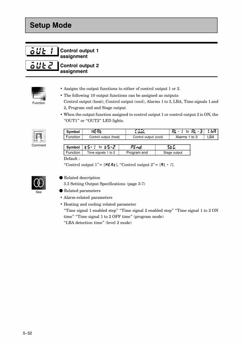
5--32
Control output 1assignment
Control output 2assignment
• Assigns the output functions to either of control output 1 or 2.
• The following 10 output functions can be assigned as outputs:Control output (heat), Control output (cool), Alarms 1 to 3, LBA, Time signals 1 and
2, Program end and Stage output
• When the output function assigned to control output 1 or control output 2 is ON, the“OUT1” or “OUT2” LED lights.
Symbol to
Function Control output (heat) Control output (cool) Alarms 1 to 3 LBA
Symbol to
Function Time signals 1 to 2 Program end Stage output
Default :“Control output 1”= [ ], “Control output 2”= [ ].
F Related description3.3 Setting Output Specifications (page 3-7)
F Related parameters
• Alarm-related parameters
• Heating and cooling related parameter
“Time signal 1 enabled step” “Time signal 2 enabled step” “Time signal 1 to 2 ONtime” “Time signal 1 to 2 OFF time” (program mode)“LBA detection time” (level 2 mode)
Setup Mode
Function
Comment
See

5--33
Auxiliary output 1 assignment
• Assigns output functions to auxiliary output 1.The following 10 output functions can be assigned as outputs:Alarms 1 to 3, LBA, Time signals 1 to 2, Program end, Stage output, Error 1 (inputerror), Error 2 (A/D converter error)
• When the output function assigned to auxiliary output 1 is ON, the SUB1 LED lights.
Symbol to to
Function Alarms 1 to 3 LBA Time signals 1 to 2
Symbol
Function Program end Stage output Error 1 Error 2
These parameters are factory-set to [ ].
F Related description3.3 Setting Output Specifications (page 3-7)
F Related parameters
• Alarm-related parameters“Time signal 1 enabled step” “Time signal 2 enabled step” “Time signal 1 to 2 ONtime” “Time signal 1 to 2 OFF time” (program mode)
“LBA detection time” (level 2 mode)
Setup Mode
Function
Comment
See

5--34
Alarm 1 type
Alarm 2 type
Alarm 3 type
Conditions of UseAlarms must be assigned as outputs. Forexample, if alarm output 1 and 2 only areassigned as outputs, the “alarm 3 type”parameter cannot be used.
• “Alarm 1 to 3 type” parameters specify the operation of the alarm by the one of theset values in the following table. For details of operation at an alarm, see page 3-10.
Set Value Settings Set Value Settings1 Upper- and lower-limit alarm 7 Lower-limit alarm with standby sequence
2 Upper-limit alarm 8 Absolute-value upper-limit alarm
3 Lower-limit alarm 9 Absolute-value lower-limit alarm
4 Upper- and lower-limit rangealarm
10 Absolute-value upper-limit alarm withstandby sequence
5 Upper- and lower-limit alarm withstandby sequence
11 Absolute-value lower-limit alarm withstandby sequence
6 Upper-limit alarm with standbysequence
Default is “2 : upper limit”.
F Related description3.4 Setting Alarm Type (page 3-10)
F Related parameters“Alarm value 1” “Alarm value 2” “Alarm value 3” (Program mode)“Alarm 1 hysteresis” “Alarm 2 hysteresis” “Alarm 3 hysteresis” (level 2 mode)“Alarm 1 open in alarm” “Alarm 2 open in alarm” “Alarm 3 open in alarm” “Control
output 1 assignment” “Control output 2 assignment” “Auxiliary output 1 assign-ment” (setup mode)
Setup Mode
Function
Comment
See

5--35
Alarm 1 open in alarm
Alarm 2 open in alarm
Alarm 3 open in alarm
Conditions of UseAlarms must be assigned as outputs. Forexample, if alarm outputs 1 and 2 only areassigned as outputs, the “alarm 3 open inalarm” parameter cannot be used.
• Sets the output states of alarms 1 to 3.
• When the controller is set to “close in alarm,” the status of the alarm output function
is output as it is. When set to “open in alarm,” the status of the alarm output functionis output inverted. The following table shows the relationship between alarm outputfunctions, alarm output and output LEDs.
Alarm Output Function Alarm Output Output LED
Close in alarmON ON Lit
Close in alarmOFF OFF Not lit
Open in alarmON OFF Lit
Open in alarmOFF ON Not lit
Setting Range Default
“ ” : Close in alarm/ “ ”:Open in alarm
F Related description3.4 Setting Alarm Type (page 3-10)
F Related parameters“Alarm value 1” “Alarm value 2” “Alarm value 3” (level 1 mode)“Alarm 1 hysteresis” “Alarm 2 hysteresis” “Alarm 3 hysteresis” (level 2 mode)
“Alarm 1 open in alarm” “Alarm 2 open in alarm” “Alarm 3 open in alarm” “Controloutput 1 assignment” “Control output 2 assignment” “Auxiliary output 1 assign-ment” (setup mode)
Direct/Reverse operation
• “Direct operation” (or normal operation) refers to control where the manipulatedvariable is increased according to the increase in the process value. Alternatively,
“reverse operation” refers to control where the manipulated variable is increasedaccording to the decrease in the process value.
Setting Range Default“ ” : Reverse operation/ “ ”:Direct operation
F Related description
3.3 Setting Output Specifications/Direct/reverse operation (page 3-8)
Setup Mode
Function
Comment
See
Function
Comment
See

5--36
• The parameters in this mode can be used only when the “security” parameter (pro-tect mode) is set to “0” and “1”.
• This mode contains the parameters for setting expanded functions. These parame-ters include parameters for setting the SP setting limitter, selecting advanced PIDand ON/OFF control, and setting the program time unit, step time/rate of rise pro-gramming, time unit of ramp rate and the automatic return of display mode.
• To select this mode, press the key for 1 second minimum. The display changesto the menu display. If you select [ ] using the and keys, and then pressthe key for 1 second minimum, the controller enters the expansion mode.
• To select parameters in this mode, press the key. To change parameter settings,use the or keys.
• The following table shows the parameters supported in this mode and the page wherethe parameter is described.
Symbol Parameter Name Page
Set point upper limit 5-37
Set point lower limit 5-37
PID/ON/OFF 5-37
Operation at power ON 5-38
End condition 5-38
Number of patterns 5-39
Program time unit 5-39
Step time/Rate of rise programming 5-40
Time unit of ramp rate 5-40
PV start 5-41
Alarm during ramp step enable 5-41
Run all enable 5-41
α 5-42
AT calculated gain 5-42
Automatic return of display mode 5-43
AT hysteresis 5-43
LBA detection width 5-43
Expansion Mode

5--37
Set point upper limit
Set point lower limit
• Limits the upper and lower limits when the SP is set. The SP can be set within therange defined by the upper and lower limit set values of the “set point upper limit”and “set point lower limit ” parameters. Note that as these parameters are reset, theSP of existing settings that are out of the range are forcibly changed to one of theupper or lower limit values.
• When the temperature input type and temperature unit have been changed, the setpoint upper limit and set point lower limit are forcibly changed to the upper andlower limits of the sensor.
• During temperature input, the decimal point position is dependent on the currentlyselected sensor, and during analog input on the results of scaling.
Parameter Setting Range Unit DefaultSet point upper limit Set point lower limit +1 to scaling upper limit EU 1300Set point lower limit Scaling lower limit to set point upper limit -1 EU -200
During temperature input, the range becomes the range of use of the selected sensorinstead of the range defined by the scaling upper and lower limit values.
F Related description4.2 Operating Condition Restrictions (page 4-7)
F Related parameter“Input type” “Scaling upper limit” “Scaling lower limit” “Decimal point” (setupmode)
PID/ON/OFF
• Selects advanced PID control or ON/OFF control.
Setting Range Default“ ” :Advance PID/ “ ” :ON/OFF
F Related description4.1 Selecting the Control Method/ON/OFF control (page 4-5)
F Related parameters“Hysteresis (heat)” “Hysteresis (cool)” (level 1 mode)
Expansion Mode
Function
Comment
See
Function
Comment
See

5--38
Operation at power ON
Selects one of the following operations when the power is turned ON:
• “Continue” : Starts operations from the state that was active when the power was
interrupted.
• “Reset” : Resets the controller.
• “Run” : Starts normal program operation.
• “Manual” : Sets the controller to the manual mode.
“Manual” cannot be selected when Auto/Manual key operation is protected.
Setting Range Default“ ” :Continue/ “ ” :Reset/ “ ” Run/ “ ” :Manual
F Related description
4.6 Setting Running Conditions/Operation at power ON (page 4-14)
End condition
• Specifies a reset state or continued control on the SP of the final step after programoperation ends.
• The program end state will not change when the “number of steps” parameter settinghas been changed after program operation ends. However, when control on the SPis continued, the SP of the final step is selected after the number of steps has beenchanged.
Setting Range Default“ ” :Reset/ “ ” :Continued control using final SP
F Related description4.6 Setting Running Conditions/End condition (page 4-15)
F Related parameter
“Number of steps” (program mode)
Expansion Mode
Function
Comment
See
Function
Comment
See

5--39
Number of patterns
• Sets the number of patterns that can be used in a program.
Setting Range Default1 to 4 1
F Related parameters“Run all enable” (expansion mode)“Event input assignment 1” (option mode)
Program time unit
• Specifies the time unit of the following parameters:“Pattern elapsing time monitor”, “Step 0 to 15 time”/Soak time 0 to 7”, “Time signal
1 ON time” “Time signal 2 ON time” “Time signal 1 OFF time” “Time signal 2 OFFtime”
Setting Range Default“ ” :Hour, minute/ “ ” :Minute, second
F Related parameters“Pattern elapsing time monitor” (level 1 mode)
“Steps 0 to 15 time/Soak time 0 to 7” “Time signal 1 ON time” “Time signal 2 ONtime” “Time signal 1 OFF time” “Time signal 2 OFF time” (program mode)
Expansion Mode
Function
Comment
See
Function
Comment
See

5--40
Step time/Rate of rise programming
• Specifies the program method.
Setting Range Default“ ” :Set time/ “ ” :Rate of rise programming
F Related description3.5 Setting Patterns (page 3-14)
4.3 Ramp Rise Rate Setup Program (page 4-9)
F Related parameter“Step 0 to 15 SP/Target SP 0 to 7” “Ramp rate 0 to 7” “Step 0 to 15 time/Soak time0 to 7” (program mode)
Time unit of ramp rate Conditions of UseRate of rise programming must be set.
• Specifies the unit time of “rate of rise 0 to 7.”
Setting Range Default“ ” : Minute/ “ ” : Hour
F Related parameter“Ramp rate 0 to 7” (program mode)
Expansion Mode
Function
Comment
See
Function
Comment
See

5--41
PV start Conditions of UseThe set time must be set.
Specifies either of the following current SP at the start of program operation:
• PV : Process value at start of program operation (PV start)
• SP : SP of step 0 (normal program operation)
When “PV” is selected, program operation is started from the position where the cur-rent SP first matches the PV at the start of program operation. If the SP does not matchthe PV, program operation is started from the beginning of the program.
Setting Range Default“ ” : PV/ “ ” :SP
F Related description4.6 Setting Running Conditions/Starting the program run/PV start (page 4-20)
Alarm during ramp step enable
• To enable alarms during the ramp step, set to [ON]. To disable alarm, set to [OFF].
Setting Range Default“ ” : / “ ”
Run all enable Conditions of UseThe “number of patterns” parameter mustbe set to a value greater than “1”.
• To successively execute the program of all patterns from pattern 0, set to [ON].
• Patterns whose “pattern execution count” parameter (level 1 mode) is set to “0” areskipped.
Setting Range Default“ ” : / “ ”
Expansion Mode
Function
Comment
See
Function
Comment
Function

5--42
α Conditions of UseThe control must be advanced PID con-trol.
• Normally, use the default value.
• Sets advanced PID-control parameter α.
Setting Range Unit Default0.00 to 1.00 None 0.65
AT calculated gain Conditions of UseThe control must be advanced PID con-trol.
• Normally, use the default value.
• Sets the gain when adjusting the PID parameters by auto-tuning.
• To give priority to response, decrease the set value of this parameter. To give priority
to stability, increase the set value of this parameter.
Setting Range Unit Default0.1 to 10.0 None 1.0
F Related parameter
“AT Execute/Cancel” (level 1 mode)“PID/ON/OFF” (expansion mode)
Expansion Mode
Function
Comment
Function
Comment
See

5--43
Automatic return of display mode
• If you do not operate any of the controller keys for the time set in this parameter whenin levels 0 to 2 and program modes, the display automatically returns to the PV/Pres-ent SP display.
• When this parameter is set to “0”, this function is disabled. (That is, the display doesnot automatically return to the PV/Present SP display.)
• This parameter is disabled while the menu display is displayed.
Setting Range Unit Default0 to 99 Second 0
AT hysteresis Conditions of UseThe control must be advanced PID con-trol.
• Normally, use the factory setting.
• The levels of limit cycle operations during AT execution are given hysteresis at event
ON/OFF switching. This parameter sets this hysteresis width.
Setting Range Unit Default0.1 to 9.9 %FS 0.2
LBA detection width Conditions of UseThe LBA (Loop Break Alarm) functionmust be assigned as an output.
• This parameter can be used when LBA is assigned as an output.
• When the change width of the manipulated variable is below the width set in this
parameter, the controller regards this as detection of an LBA.
Setting Range Unit Default0.0 to 999.9 %FS 0.2
Expansion Mode
Function
Comment
Function
Comment
Function
Comment

5--44
• The parameters in this mode can be used only when the “security” parameter (pro-tect mode) is set to “0” and “1”.
• You can select this mode only on controllers that support optional functions. In thismode, you can set the communications conditions, transfer output and event inputparameters to match the type of optional function supported on the controller.
• To select this mode, press the key for 1 second minimum. The display changes
to the menu display. If you select [ ] using the and keys, and then pressthe key for 1 second minimum, the controller enters the option mode.
• To select parameters in this mode, press the key. To change parameter settings,
use the or keys.
• The following table shows the parameters supported in this mode and the page wherethe parameter is described.
Symbol Parameter Name Page
Event input assignment 1 5-45
Communication stop bit 5-46
Communication data length 5-46
Communication parity 5-46
Communication baud rate 5-46
Communication unit No. 5-46
Transfer output type 5-47
Transfer output upper limit 5-47
Transfer output lower limit 5-47
Option Mode

5--45
Event input assignment 1 Conditions of UseThe event input function must be in use.
• The following functions are assigned as event inputs:“Run/reset,” “Auto/manual,” “Hold/hold cancel,” “Advance,” “Pattern select 0 to 1”
• Weighting of the remote/local function is as follows:Pattern select 0 = 20, Pattern select 1 = 22
• When event input is used as advance input, program steps are advanced at the rising
edge (OFF!ON) of the event input signal. When event input is used as run/reset in-put, the program is reset at the rising edge (OFF!ON) of the event input signal, andthe program runs at the falling edge (ON!OFF). Other signals are accepted as dur-ing regular operation.
Settings Function
Event input disabled
OFF ON : Reset /ON OFF : Run
ON : Manual /OFF : Auto
ON : Hold /OFF : Hold cancel
OFF ON Execution
OFF: pattern 0 / ON: pattern 1 (*1)
OFF: pattern 0 / ON: pattern 2 (*2)
*1 Enabled when the “number of patterns” parameter is set to “2” or more
*2 Enabled when the “number of patterns” parameter is set to “3” or more
• Default is “ ”.
F Related description4.7 How to Use Event input (page 4-23)
F Related parameters“Remote/local” (level 2 mode)“Hold” “Advance” (level 0 mode)“Pattern No.” (level 0/program mode)
F Option unitsE53-CKB
Option Mode
Function
Comment
See
Model

5--46
Communication stop bit
Communication data length
Communication parity
Communication baud rate
Communication unit No.
Conditions of UseThe communications function must be inuse.
• These parameters are enabled when the power is turned ON again.
• These parameters set the communications conditions. Make sure that the stop bit,data length, parity and baud rate of the host computer and the E5CK-T controller arematching.
• When connecting two or more E5CK-T controllers to the host computer, set unit Nos.that will not conflict with the unit Nos. of other controllers.
• “Communication stop bit” parameter
Setting Range Unit Default1, 2 Bits 2
• “Communication data length” parameter
Setting Range Unit Default7, 8 Bits 7
• “Communication parity” parameter
Setting Default
“ ”: None/ “ ”:Even/“ ”:Odd
• “Communication baud rate” parameter
Setting Range Unit Default1.2, 2.4, 4.8, 9.6, 19.2 kbps 9.6
• “Communication unit No.” parameter
Setting Range Unit Default0 to 99 None 0
F Related descriptionChapter 6 Using the Communications Functions
F Related parameter“Remote/Local” (level 2 mode)
F Option unitsE53-CK01/03
Option Mode
Function
Comment
See
Model

5--47
Transfer output type
Transfer output upper limit
Transfer output lower limit
Conditions of UseThe transfer output function must be inuse.
• These parameters set the transfer output conditions.
• The “transfer output type” parameter selects one of the following data items as thetransfer output type, and assigns this to transfer output:Present SP, Process value, Manipulated variable (heat), Manipulated variable (cool)(during heating and cooling control)
• The “transfer output upper limit” and “transfer output lower limit” parameters areused for scaling of transfer output. The setting range varies according to this outputdata. Also, a lower limit value larger than the upper limit value may be set.
• During temperature input, the decimal point position of the set point or process valueis dependent on the currently selected sensor, and during analog input on the resultsof scaling.
• Set the scaling of the present SP or process value within the sensor input indication
range.
Transfer Output Type Transfer Output Lower Limit toTransfer Output Upper Limit
“ ” Present SP -1999 to 9999
“ ” Process Value -1999 to 9999
“ ” Manipulated variable (heat) -5.0% to 105.0% (standard control), 0.0 to 105.0% (heatingand cooling control)
“ ” Manipulated variable (cool) 0.0 to 105.0%
• Default : [ ].
F Related description4.9 How to Use Transfer Output (page 4-21)
F Option unitsE53-CKF
Option Mode
Function
Comment
See
Model

5--48
• The parameters in this mode can be used only when the “security” parameter (pro-tect mode) is set to “0”. When selecting this mode for the first time after the E5AK-Thas left the factory, return the “security” parameter to “0”.
• This mode contains the parameters for user calibration of inputs and outputs. Onlyparameters relating to input types specified in the “input type” parameter (setupmode) can be used. Also, related output parameters can be used only when the com-
munications unit (E53-CKF) is addedon.
• To select this mode, press the key for 1 second minimum. The display changesto the menu display. If you select [ ] using the and keys, and then pressthe key for 1 second minimum, the controller enters the calibration mode.
• For details on parameters in the calibration mode, see Chapter 7 Calibration.
Calibration Mode

CHAPTER 6 USING THE COMMUNICATIONS FUNCTION
6--1
CHAPTER 6USING THECOMMUNICATIONSFUNCTION
This chapter mainly describes communications with a host computerand communications commands.
CHAPTER6
6.1 Outline of the Communications Function 6-2.
Outline 6-2. . . . . . . . . . . . . . . . . . . . . . . . . . . . . . .
Transfer procedure 6-2. . . . . . . . . . . . . . . . . . . . .
Interface 6-2. . . . . . . . . . . . . . . . . . . . . . . . . . . . . .
6.2 Preparing for Communications 6-3. . . . . . . . . .
Cable connections 6-3. . . . . . . . . . . . . . . . . . . . . .
Setting the communications specifications 6-4
6.3 Command Structure 6-5. . . . . . . . . . . . . . . . . . . .
6.4 Commands and Responses 6-7. . . . . . . . . . . . . .
Reading/writing parameters 6-7. . . . . . . . . . . . .
Issuing special commands 6-10. . . . . . . . . . . . . . .
Reading/writing program parameters 6-12. . . .
6.5 How to Read CommunicationsError Information 6-15. . . . . . . . . . . . . . . . . . . . .
End code 6-15. . . . . . . . . . . . . . . . . . . . . . . . . . . . . .
Undefined error 6-16. . . . . . . . . . . . . . . . . . . . . . . .
6.6 Program Example 6-17. . . . . . . . . . . . . . . . . . . . . .
How to use programs 6-17. . . . . . . . . . . . . . . . . . .
Program list 6-18. . . . . . . . . . . . . . . . . . . . . . . . . . .
Examples of use 6-19. . . . . . . . . . . . . . . . . . . . . . . .

6--2
6.1 Outline of the Communications Function
The communications function allows you to monitor and set E5CK-T pa-rameters by a program prepared and running on a host computer con-nected to the E5CK-T controller. This chapter describes operations as
viewed from the host computer.
When the communications function is used, the E53-CK01/03 commu-nications unit must be added on.
The E5CK-T communications function allows you to carry out the follow-ing:
• Read/write parameters
• Instruct operations
• Select the setting level.
The communications function assumes the following conditions:
• Writing of parameters is possible only during remote operation. Also,parameters cannot be written during execution of auto-tuning.
• Writing of parameters is limited by setting level. Writing conditions areas follows depending on the setting level:
• Setting level 1: No restrictions
• Setting level 0: Writing of parameters in the setup, expansion and option modes only is prohibited.
• The “remote/local”, “AT execute/cancel”, “hold/hold cancel” and“advance” parameters are set aside from other parameters as specialcommands for instructing operations.
The host computer sends a “command frame” to the controller, and thecontroller returns a “response frame” corresponding to the content of thecommand sent by the host computer. In other words, a response frame isreturned for each command frame sent.The following diagram shows command frame/response frame opera-tions.
Command frame Command frame
Response frame
Host computerE5CK-T
The host computer carries out communications conforming to theRS-232C, RS-422 or RS-485 interface specifications.Controllers supporting the RS-232C, and RS-485 specifications are as fol-lows:
• Option unitsE5-CK01: RS-232CE5-CK03: RS-485
JJOutline
JJTransferprocedure
JJ Interface

6--3
6.2 Preparing for Communications
For details on wiring when the communications function is used, seeChapter 2 Preparations.
JJCable connections• Only one controller can be connected to the host computer.
(1:1 connection)
• The cable length should not exceed 15 meters.
• Use shielded twisted-pair cables (AWG28 or more) for the cables.
RS-232CNo.
13 SDRD14
1 SG
E5CK-TIBM-PC/XTDE-25FemaleDTE
(SD) TXD
(RD) RXD
(RS) RTS
(CS) CTS
(SG) COMMON
(ER) DTR
(DR) DSR
2
3
4
5
20
6
7
FG 1
25 pins
• 1:1 or 1:N connections are allowed. In a 1:N connection, up to 32 control-lers including the host computer can be connected.
• The total cable length should not exceed 500 meters.
• Use shielded twisted-pair cables (AWG28 or more) for the cables.
• Attach terminators to the controllers at both ends of the series of con-trollers connected in an open configuration. For example, in the follow-ing configuration, connect the terminator to unit No.30, and do not con-nect terminators to unit Nos.0 to 29.
• Use terminators having a resistance of 120 Ω (1/2 W). The total resis-tance of both ends should be at least 54 Ω.
-
+
FG
RS-485No.
32
31
RS-485No.
32 A
B31
Host computerRS-485
Shielded cable
E5CK-T (No.0) E5CK-T (No.30)
Terminator(120Ω 1/2W)
A
B
A < B : “1” MarkA > B : “0” Space
19
20
A
B
19 A
B20
FF RS-232C
FF RS-485

CHAPTER 6 USING THE COMMUNICATIONS FUNCTION
6--4
Match the communications specifications of the host computer andE5CK-T controller. When two or more controllers are connected to thehost computer, make sure that the communications specifications of allcontrollers are the same.
This section describes how to set the communications specifications forthe E5CK-T controller. For details on the host computer, see the relevantmanual supplied with the host computer.
Set the communications specifications of the E5CK-T in the controller’scommunications parameters. The communications parameters are set on
the front panel of the E5CK-T controller.The following table shows the communications parameters (option mode)provided on the E5CK-T controller and their respective settings.
Parameter/Symbol Setting Set ValueUnit No. 0 to 99 0 to 99
Baud rate 1.2/2.4/4.8/9.6/19.2 (kbps) 1.2/2.4/4.8/ 9.6 /19.2Bit length 7/8 (bit) 7 /8Parity None/even/odd / /
Stop bit 1/2 1/ 2
Inverted items are factory settings.
JJSetting the com-municationsspecifications
FF Communicationsparameters

6.3 Command Structure
6--5
6.3 Command Structure
Command structure is as follows. Each command is paired with a re-sponse.
UnitNo.
Commandcode
Data FCS
CR
Command type
@ *
2B 1B 2B 4B 2B 2B
Command
UnitNo.
Commandcode
Data FCS
Command type
CR
Endcode@ *
2B 1B 2B 4B 2B 2B2B
Response
End code = 00
UnitNo.
Commandcode
FCS
Command type
CR
Endcode@ *
2B 1B 2B 2B 2B2B
End code = 00
Response
• “@”The start character. This character must be inserted before the leadingbyte.
• Unit No.Specifies the “unit No.” of the E5CK-T. If there are two or more trans-mission destinations, specify the desired destination using “unit No.”
• Command type
Code Command type1 Parameter read2 Parameter write3 Special command4 Program parameter read5 Program parameter write
• Command codeSpecifies the command for each command type. With parameter read/write commands and program parameter read/write commands, this be-comes the parameter No.
• DataSpecifies the set value or setting content. With the parameter read andprogram parameter read commands, set dummy data “0000”. In the re-sponse, this is inserted only when the end code is “00”.
Currently, if a command is used for invalid parameters (parameters that do not satfy the conditions of use in Chapter 5), the “undefined” error (end code: IC) responis returned.
About invalidparameters

CHAPTER 6 USING THE COMMUNICATIONS FUNCTION
6--6
• End codeSets the communication results. For details on the types and meaningsof end codes, see 6.5 How to Read Communications Error Information(page 6-12).
• FCS (Frame Check Sequence)Set the frame check results from the start character to the data area. Fordetails on the frame check, see 6.6 Program Example (page 6-18).
• “*” “CR (Carriage Return) code”Indicates the end (terminator) of the command or response block.
F Conversion to ASCII code at each digit of the calculation result and setting to FCS
Calculate the exclusive OR from the start character to the data section. The folloing describes an example of how to calculate the FCS for “@001000000”.
How to CalculateFCS
(1) Convert the ASCII codes of each character to Hexadecimal “40H, 30H, .
30H”.
(2) Calculate the exclusive OR of all characters.
(3) Convert to ASCII code. ( “4B”)
(4) Set the result as FCS.
F ASCII Hex
ASCII @ 0 0 1 0 0 0 0 0 0
Hex 40H 30H 30H 31H 30H 30H 30H 30H 30H 30H
F Completed frame (with appended terminator)
F Exclusive OR
ASCII @ 0 0 1 0 0 0 0 0 0 7 1
Hex 40H 30H 30H 31H 30H 30H 30H 30H 30H 30H 37H 31H
ASCII @ 0 0 1 0 0 0 0 0 0 7 1 * CR
Hex 40H 30H 30H 31H 30H 30H 30H 30H 30H 30H 37H 31H 2AH 0DH
FCS
FCS Terminator
40H¨30H¨30H¨31H¨30H¨30H¨30H¨30H¨30H¨30H¨=71H

6.4 Commands and Responses
6--7
6.4 Commands and Responses
This section describes commands and response in detail. The conventionsused in this section and data restrictions are as follows:
• Data is expressed in 1-byte units and in ASCII code.
• When the read or write data is a numerical value, the data to be set mustconform to the following conditions:
(1) The decimal point “.” is not indicated in fractions.(2) The leftmost bit of minus numerical data must be expressed as fol
lows:A: -1, F: - (minus)[example]
10.0=[0100], -150.0=[A500], -15=[F015]
JJReading/writing parameters
FF Reading parameters
Command
ParameterNo.
ParameterNo.
UnitNo.
FCS
CR
UnitNo.
Read data FCS
CR
Endcode
@
@
*
*
2B 2B 4B 2B 2B
2B 2B 4B 2B 2B2B
1 0 0 0 0
1Response
FFWriting parameters
Command
ParameterNo.
ParameterNo.
UnitNo.
Write data FCS
CR
UnitNo.
Write data FCS
CR
Endcode
@
@
*
*
2B 2B 4B 2B 2B
2B 2B 4B 2B 2B2B
2
2Response
Parameters of a specified controller are read or written.
• Writing is possible only during remote operation.
• Reading is impossible during execution of auto-tuning.
• The following are set aside as special commands. For details, see page6-10.
• “AT execute/cancel”, “Hold/Hold cancel” and “Advance”
• For details on parameters in each setting level, see the tables on page 6-8and 6-9.

CHAPTER 6 USING THE COMMUNICATIONS FUNCTION
6--8
Parameter No. Parameter Data Setting and Monitor Range Mode
00 PV monitor *1 *2 Scaling lower limit -10% to scaling upper limit +10%
01 Set point *1 Set point lower limit to set point upper limitLevel 0
04 MV monitor (heat) *1 -5.0 to 105.0Level 0
14 Valve opening monitor *1 -10.0 to 110.0 Level 0
02 Alarm value 1 -1999 to 9999
03 Alarm value 2 -1999 to 9999 Program
41 Alarm value 3 -1999 to 9999
Program
19 Proportional band 0.1 to 999.9
20 Integral time 0 to 3999
21 Derivative time 0 to 3999
22 Cooling coefficient 0.01 to 99.99
09 Dead band -19.99 to 99.99
23 Manual reset value 0.0 to 100.0 Level 1
06 Hysteresis (heat) 0.01 to 99.99
Level 1
43 Hysteresis (cool) 0.01 to 99.99
07 Control period (heat) 1 to 99
08 Control period (cool) 1 to 99
46 LBA detection time 0 to 9999
47 MV at reset *5 -5.0 to 105.0
48 MV at PV error *5 -5.0 to 105.0
50 MV upper limit *3 MV lower limit +0.1 to 105.0
49 MV lower limit *4 -5.0 to MV upper limit -0.1
51 MV change rate limit 0.0 to 100.0
56 Input digital filter 0 to 9999 Level 2Level 2
25 Alarm 1 hysteresis 0.01 to 99.99
26 Alarm 2 hysteresis 0.01 to 99.99
52 Alarm 3 hysteresis 0.01 to 99.99
53 Input shift upper limit -199.9 to 999.9
54 Input shift lower limit -199.9 to 999.9
*1 Possible only during reading*2 During temperature input, the range becomes the range of use of the selected sensor.*3 During heating and cooling control, the range becomes 0.0 to 105.0.*4 During heating and cooling control, the range becomes -105.0 to 0.0.*5 During heating and cooling control, the range becomes -105.0 to 105.0.
*3
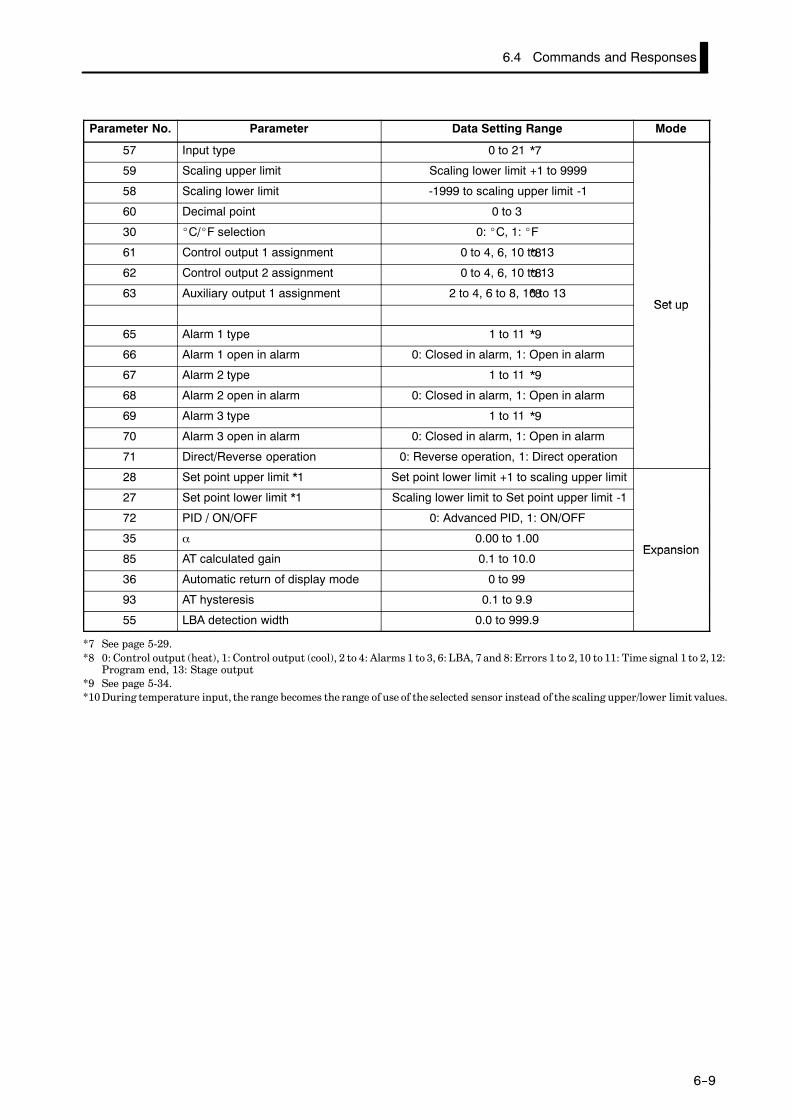
6.4 Commands and Responses
6--9
Parameter No. Parameter Data Setting Range Mode
57 Input type 0 to 21
59 Scaling upper limit Scaling lower limit +1 to 9999
58 Scaling lower limit -1999 to scaling upper limit -1
60 Decimal point 0 to 3
30 _C/_F selection 0: _C, 1: _F
61 Control output 1 assignment 0 to 4, 6, 10 to 13
62 Control output 2 assignment 0 to 4, 6, 10 to 13
63 Auxiliary output 1 assignment 2 to 4, 6 to 8, 10 to 13Set upSet up
65 Alarm 1 type 1 to 11
66 Alarm 1 open in alarm 0: Closed in alarm, 1: Open in alarm
67 Alarm 2 type 1 to 11
68 Alarm 2 open in alarm 0: Closed in alarm, 1: Open in alarm
69 Alarm 3 type 1 to 11
70 Alarm 3 open in alarm 0: Closed in alarm, 1: Open in alarm
71 Direct/Reverse operation 0: Reverse operation, 1: Direct operation
28 Set point upper limit *1 Set point lower limit +1 to scaling upper limit
27 Set point lower limit *1 Scaling lower limit to Set point upper limit -1
72 PID / ON/OFF 0: Advanced PID, 1: ON/OFF
35 α 0.00 to 1.00Expansion
85 AT calculated gain 0.1 to 10.0Expansion
36 Automatic return of display mode 0 to 99
93 AT hysteresis 0.1 to 9.9
55 LBA detection width 0.0 to 999.9
*7 See page 5-29.*8 0: Control output (heat), 1: Control output (cool), 2 to 4: Alarms 1 to 3, 6: LBA, 7 and 8: Errors 1 to 2, 10 to 11: Time signal 1 to 2, 12:
Program end, 13: Stage output*9 See page 5-34.*10 During temperature input, the range becomes the range of use of the selected sensor instead of the scaling upper/lower limit values.
*7
*8
*8
*8
*9
*9
*9

CHAPTER 6 USING THE COMMUNICATIONS FUNCTION
6--10
JJ Issuing special commands
Commandcode
Commandcode
UnitNo.
Instruction code FCS
CR
UnitNo.
Instruction code FCS
CR
Endcode
@
@
*
*
2B 2B 4B 2B 2B
2B 2B 4B 2B 2B2B
3
3
Command
Response
The following functions are issued as special commands.
• Run/ResetRuns or stops programs. This command cannot be issued in setting level1.
• AT Execute/CancelExecutes or cancels auto-tuning. This command cannot be issued in set-ting level 1.
• Move to setting level 1Issue this command when writing parameters in the setup, expansionand option modes. On the E5CK-T, the parameter switches to the top pa-rameter “ : input type” of the setup mode, and control is stopped.
• Software resetResets E5CK-T operation (same as turning power ON) by communica-tions. A response is not returned to this command. Also, communica-tions with the E5CK-T cannot be carried out for five seconds after reset.
• StatusMonitors the status of the E5CK-T. Two command groups are available,A and B, depending on the instruction code. The response is returned inbit units to the instruction code (4B) of the response frame. For detailson the monitoring details of each group, see page 6-11.
• HoldHolds program execution or cancels hold. This command cannot be is-sued in setting level 1.
• AdvanceAdvances execution of steps in the program. This command cannot beissued in setting level 1.
00 Run/Reset 0000: Run, 0001: Reset
02 Remote/Local 0000: Local, 0001: Remote
07 AT Execute/Cancel 0000: Cancel, 0001: 40% AT execu-tion, 0002: 100% AT execution
09 Move to setting level 1 0000
11 Software reset 0000
14 Status 0000: A group, 0001: B group
15 Hold 0000: Hold cancel, 0001: Hold
16 Advance 0000
In the case of the “Run/Reset” or “Advance” command, is sue commandwhen the response of the previous command was returned and passed for0.5 seconds.

6.4 Commands and Responses
6--11
FF A groupBit Description [1] [0]
0 Heating side output ON OFF *1
1 Cooling side output ON OFF
2 Alarm output 1 ON OFF *2
3 Alarm output 2 ON OFF *2
4 Alarm output 3 ON OFF *2
5 LBA output ON OFF *2
6
7 Run/Reset Reset Run
8 Auto/Manual Manual Auto
9 Remote/Local Remote Local
10
11 AT AT execution OFF
12 Hold During hold OFF
13
14
15
FF B groupBit Description [1] [0]
0 Setting level 1 0
1
2 Control output 1 type Linear Pulse
3
4
5 Input error ON OFF
6 A/D converter error ON OFF
7
8
9
10
11 Time signal 1 output ON OFF *2
12 Time signal 2 output ON OFF *2
13 Ramp/soak Ramp Soak
14 Program end ON OFF *4
15 During standby ON OFF
*1 Always “OFF” at linear output*2 Always “OFF” when output is not assigned*3 When the ON time during control output is less than 190 ms, the heater current to which
“ 1” is set and the previous current value is held.*4 “ON” while the No.2 display indicates [ ]. For details on the [ ] indication, see
page 4-15.
To return to setting level 0 from setting level 1, issue the “software reset” commanIf the parameter write command is issued for the setup, expansion and option modin setting level 0, an error occurs, and the end code (0D = Command cannot bexecuted) is returned.
About Setting Levels

CHAPTER 6 USING THE COMMUNICATIONS FUNCTION
6--12
JJReading/writing program parameters
FF Reading parameters
ParameterNo.
ParameterNo.
UnitNo.
FCS
CR
UnitNo.
Read data FCS
CR
Endcode
@
@
*
*
2B 2B 4B 2B 2B
2B 2B 4B 2B 2B2B
4 0 0 0 0
4
Command
Response
FF Writing parameters
ParameterNo.
ParameterNo.
UnitNo.
Write data FCS
CR
UnitNo.
Write data FCS
CR
Endcode
@
@
*
*
2B 2B 4B 2B 2B
2B 2B 4B 2B 2B2B
5
5
Command
Response
Parameters relating to the program of the specified unit are read or writ-ten.
• Writing is possible only during remote operation.
• Reading is impossible during execution of auto-tuning.
• For details on parameters in each setting level, see the lists for each set-ting level on pages 6-13 to 6-14.

6.4 Commands and Responses
6--13
Parameter No. Parameter Data Setting and Monitor Range Mode
00 Pattern No. *2 0 to number of patterns -1 *2
01 Step No. monitor *1 0 to number of steps -1
63 Standby time monitor *1 0.00 to 99.59Level 0
02 Pattern elapsing time monitor *1 0.00 to 99.59Level 0
03 Pattern execution count monitor *1 0 to 9999
60 Number of steps 1 to 16
05 Step 0 SP/Target SP 0 SP lower limit to SP upper limit
06 Ramp rate 0 0 to 9999
07 Step 0 time/Soak time 0 0.00 to 99.59
08 Step 1 SP/Target SP 1 SP lower limit to SP upper limit
09 Ramp rate 1 0 to 9999
10 Step 1 time/Soak time 1 0.00 to 99.59
11 Step 2 SP/Target SP 2 SP lower limit to SP upper limit
12 Ramp rate 2 0 to 9999
13 Step 2 time/Soak time 2 0.00 to 99.59
14 Step 3 SP/Target SP 3 SP lower limit to SP upper limit
15 Ramp rate 3 0 to 9999
16 Step 3 time/Soak time 3 0.00 to 99.59
17 Step 4 SP/Target SP 4 SP lower limit to SP upper limit
18 Ramp rate 4 0 to 9999
19 Step 4 time/Soak time 4 0.00 to 99.59
20 Step 5 SP/Target SP 5 SP lower limit to SP upper limit
21 Ramp rate 5 0 to 9999
22 Step 5 time/Soak time 5 0.00 to 99.59 Program
23 Step 6 SP/Target SP 6 SP lower limit to SP upper limit
Program
24 Ramp rate 6 0 to 9999
25 Step 6 time/Soak time 6 0.00 to 99.59
26 Step 7 SP/Target SP 7 SP lower limit to SP upper limit
27 Ramp rate 7 0 to 9999
28 Step 7 time/Soak time 7 0.00 to 99.59
29 Step 8 SP SP lower limit to SP upper limit
30 Step 8 time 0.00 to 99.59
31 Step 9 SP SP lower limit to SP upper limit
32 Step 9 time 0.00 to 99.59
33 Step 10 SP SP lower limit to SP upper limit
34 Step 10 time 0.00 to 99.59
35 Step 11 SP SP lower limit to SP upper limit
36 Step 11 time 0.00 to 99.59
37 Step 12 SP SP lower limit to SP upper limit
38 Step 12 time 0.00 to 99.59
39 Step 13 SP SP lower limit to SP upper limit
40 Step 13 time 0.00 to 99.59
*1 Reading only is possible.*2 Can be used in either the level 0 or program modes.
Read only during program run

CHAPTER 6 USING THE COMMUNICATIONS FUNCTION
6--14
Parameter No. Parameter Data Setting and Monitor Range Mode
41 Step 14 SP SP lower limit to SP upper limit
42 Step 14 time 0.00 to 99.59
43 Step 15 SP SP lower limit to SP upper limit
44 Step 15 time 0.00 to 99.59
04 Pattern execution count 0 to 9999
45 Time signal 1 enabled step 0 to 15 Program
46 Time signal 1 ON time 0.00 to 99.59
Program
47 Time signal 1 OFF time 0.00 to 99.59
48 Time signal 2 enabled step 0 to 15
49 Time signal 2 ON time 0.00 to 99.59
50 Time signal 2 OFF time 0.00 to 99.59
62 Standby time 0.00 to 99.59 Level 2
54 Operation at power ON *3
55 End condition 0: Reset, 1: Final step SP
61 Number of patterns 1 to 4
51 Program time unit 0: Hour, minute, 1: Minute, second
56 Step time/Rate of rise programming 0: Step time, 1: Rate of rise programming Expansion
57 Time unit of ramp rate 0: Minute, 1: Hour
Expansion
58 PV start 0: SP start, 1: PV start
52 Alarm during ramp step enable 0: OFF, 1: ON
53 Run all enable 0: OFF, 1: ON
*3 0: Continue, 1: Reset, 2: Run, 3: Manual

6.5 How to Read Communications Error Information
6--15
6.5 How to Read Communications Error Information
The result of communications on the E5CK-T can be checked by the end code or undefined error responsein the response frame. Use this end code or undefined error response to remedy errors that may occur.
Communications are normal when the end code in the response is “00”.If the end code is not “00”, this indicates that an error that is not an unde-fined error has occurred. The end code format is as follows and does notcontain a data area.
CR
UnitNo.
Commandcode
FCS
Command type
Endcode@ *
End code 0D Code name Command cannot be executed
• Writing was carried out during local operation.
• Writing was carried out during execution of auto-tuning.
• An attempt was made to execute 40%AT during heating and cooling con-trol.
• An attempt was made to switch run/reset in setting level 1.
• An attempt was made to execute AT in setting level 1.
• Issue the parameter read or write commands in conditions other thanabove.
End code 10 Code name Parity error
Parity check error was detected in the received data.
Check the communications conditions. If the communications conditionsof the host computer and E5CK-T controller match, then a probable causeis a problem in the communications circuit of one or both of the host com-puter and E5CK-T controller.
End code 11 Code name Framing error
Stop bit cannot be detected.
Check the communications conditions. If the communications conditionsof the host computer and E5CK-T controller match, then a probable causeis a problem in the communications circuit of one or both of the host com-puter and E5CK-T controller.
Responses are not returned unless the target unit for communications and the unNo. defined in the command match.
About the Unit No.
JJEnd code
FF Description
FF Action
FF Description
FF Action
FF Description
FF Action

CHAPTER 6 USING THE COMMUNICATIONS FUNCTION
6--16
End code 13 Code name FCS error
The FCS (Frame Check Sequence) do not match.
Check the FCS program.
End code 14 Code name Format error
The received command length does not match the length defined in theframe format.
Check the communications conditions. If the communications conditionsof the host computer and E5CK-T controller match, then a probable causeis a problem in the communications circuit of one or both of the host com-puter and E5CK-T controller.
End code 15 Code name Setting range error
Numerical values or code values in the data are not within the settingrange.
Check the parameter and read or write data of special commands.
JJUndefined error
CR
UnitNo.
FCS
@ *
2B2B 2B 2B
CI
• An undefined header code has been received.
• A currently invalid parameter (e.g. the scaling command during temper-ature input) has been received.
• Check the parameter No.
FF Description
FF Action
FF Description
FF Action
FF Description
FF Action
FF Description
FF Action

6.6 Program Example
6--17
6.6 Program Example
JJHow to use programsThe program described below obtains corresponding response frame data when some
of the command frame data is input.The input format is as follows. The FCS and terminator are automatically generated,and need not be input.
CR
UnitNo.
Commandcode
Data FCS
Command type
@ *
2B2B 1B 2B 4B 2B
Input these data. These are automaticallygenerated.
The output format is as follows. The content of the response frame is displayed as it is.
UnitNo.
Commandcode
Data FCS
Command type
CR
Endcode@ *
2B 1B 2B 4B 2B 2B2B
FF Procedure(1) Read the program.
(2) Enter “RUN”.
(3) When “send data:” is displayed, enter the command data (from @ to the commandstring).
(4) The content of the response frame is displayed following “receive data:”.
FF Conditions when running a program• Set the communications conditions as follows:
Baud rate : 9600 bpsBit length : 7 bits
Parity : EvenStop bit : 2
• Make sure that the communications cable is properly connected.

CHAPTER 6 USING THE COMMUNICATIONS FUNCTION
6--18
JJProgram list (language: IBM PC Compatible Machine)
1000 ’1010 ’ PROGRAM : E5CK-T COMMUNICATION PROGRAM1020 ’ FOR IBM PC COMPATBLE MACHINE1050 ’1060 ’ Default RS-232C SPEED: 9600BPS, PARITY: EVEN, DATA: 7, STOP: 21070 OPEN “COM: E73” AS #11080 *REPEAT1090 ’ Enter send data1100 INPUT “send data : ” , SEND$1110’ FCS calculation1120 FCS=01130 FOR IFCS=1 TO LEN (SEND$)1140 FCS=FCS XOR ASC (MID$ (SEND$, IFCS, 1))1150 NEXT1160 FCS$=RIGHT$ (“0”+HEX$ (FCS), 2)1170 ’ Execute communications1180 ZZZ$=SEND$+FCS$+“*”+CHR$ (13)1190 PRINT #1, ZZZ$;1120’ Check response1210 RECCNT=0: TMP$=“”1220 *DRECLOOP:1230 IF LOC (1) < > 0 THEN DREC11240 RECCNT=RECCNT+11250 IF RECCNT=5000 THEN *DRECERR ELSE DRECLOOP1260 *DREC11270 TMP$=TMP$+INPUT$ (LOC (1), #1)1280 IF RIGHT$ (TMP$, 1)=CHR$ (13) THEN *DRECEND
ELSE RECCNT=0: GOTO *DRECLOOP1290 *DRECERR1300 TMP$=“No response !!” +CHR$ (13)1310 *DRECEND1320 RECV$=TMP$1330 PRINT “receive data : ” ; RECV$1340 ’ Repeat to make Command1350’ GOTO *REPEAT1360 ’ END1370 CLOSE #11380 END
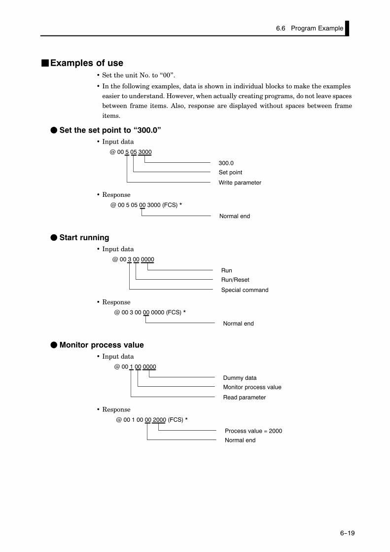
6.6 Program Example
6--19
JJExamples of use• Set the unit No. to “00”.
• In the following examples, data is shown in individual blocks to make the exampleseasier to understand. However, when actually creating programs, do not leave spacesbetween frame items. Also, response are displayed without spaces between frame
items.
FF Set the set point to “300.0”• Input data
@ 00 5 05 3000
300.0
Set point
Write parameter
• Response
@ 00 5 05 00 3000 (FCS) *
Normal end
FF Start running• Input data
@ 00 3 00 0000
Run
Run/Reset
Special command
• Response
@ 00 3 00 00 0000 (FCS) *
Normal end
FF Monitor process value• Input data
@ 00 1 00 0000
Dummy data
Monitor process value
Read parameter
• Response
@ 00 1 00 00 2000 (FCS) *
Process value = 2000
Normal end

CHAPTER 7 CALIBRATION
7--1
CHAPTER 7CALIBRATION
This chapter describes procedures for each calibration operation.Read this chapter only when the controller must be calibrated.
CHAPTER7
7.1 Parameter Structure 7-2. . . . . . . . . . . . . . . . . . .
7.2 Calibrating Thermocouples 7-4. . . . . . . . . . . . .
7.3 Calibrating PlatinumResistance Thermometers 7-7. . . . . . . . . . . . . . .
7.4 Calibrating Current Input 7-9. . . . . . . . . . . . . .
7.5 Calibrating Voltage Input 7-10. . . . . . . . . . . . . . .
7.6 Checking Indication Accuracy 7-12. . . . . . . . . . .

7--2
7.1 Parameter Structure
• To calibrate the E5CK-T controller, select [ ] in the menu displayto select the calibration mode. [ ] .is displayed.
• However, note that [ ] may not be displayed on the menu displaywhen, for example, the user is calibrating the E5CK-T controller for thefirst time. If this happens, [ ] is displayed by changing the “security”parameter (protect mode) to “0”.
• The parameters in the calibration mode are structure as follows:
0 to 10V0 to 5V 1 to 5V
Thermocouple
Thermocouple 1
Transfer output
Data storage
Platinum resistancethermometer Voltage inputCurrent input
Thermocouple 2
Thermocouple 1 : K1/J1/L1/E/N/W/PLIIThermocouple 2 : K2/J2/L2/R/S/B/T/UPlatinum resistancethermocouple :JPt100/Pt100
Only when thetransfer outputfunction is sup-ported
• To select the desired parameter, press the key. Parameters are dis-played in the following order:
Calibration of inputs → Calibration of transfer output →Storage of calibration data
If the E5CK-T controller does not support the transfer output function,calibration of transfer output is automatically deleted from the calibra-tion procedure as follows:
Calibration of inputs → Storage of calibration data• Only inputs that have been set in the “input type” parameter (setup
mode) can be calibrated. To temporarily store data for each of the cal-ibration parameters, press the key for 1 second.
• Transfer output can be calibrated only when the Communications unit(E53-CKF) is set in the controller. To adjust data items, press the or
keys.
• The data store menu is displayed only when all calibration items havetemporarily been stored.
• After calibrating input, you must always check indication accuracy. Fordetails, see page 7-12.

7--3
• Parameters are displayed on the No.1 display, and the process value isdisplayed in Hexadecimal on the No.2 display.
• Normally, the process value changes by several digits. The process valueflashes, for example, when a sensor error causes the process value tostray from the calibration target range.
• When the process value display is flashing, the process value is not storedas data even if the key is pressed.
• Once the E5CK-T controller has been calibrated by the user, [ ] isdisplayed preceded by the “.” mark when the calibration mode is next se-lected.
FF Calibration itemmenu
Calibration itemparameter
Process value
FF Calibration storemark
Calibration store mark

CHAPTER 7 CALIBRATION
7--4
7.2 Calibrating Thermocouples
• Calibrate according to the type of thermocouple, thermocouple 1 group(K1, J1, L1, E, N, W, PLII) and thermocouple 2 group (K2, K2, L2, R, S,B, T, U).
• When calibrating, do not cover the bottom of the controller. Also, do nottouch the input terminals (Nos.6 and 7) or compensating conductor onthe E5CK-T controller.
FF Preparations
5
4
3
2
1
1211
DMM
STV
Cold junctioncompensator
0_C/32_F
Compensatingconductor
10
9
8
7
61413
AC100-240V(AC/DC24V )
~
SOURCE
• Set the cold junction compensator designed for compensation of inter-nal thrmocuples to 0_C. However, make sure that internal thermocou-ples are disabled (tips are open).
• In the above figure, STV refers to a standard DC current/voltage source,and DMM refers to a precision digital multimeter.However, note that DMM is required only when the transfer outputfunction is supported.
• Use the compensating conductor on the selected thermocouple. Howev-er, note that when thermocouple R, S, E, B, W and PLII is used, the coldjunction compensator and the compensating conductor can be substi-tuted with the cold junction compensator and the compensating conduc-tor for thermocouple K.
Correct process values cannot be obtained if you touch the contact ends of the compensating conductor during calibration of a thermocouple. Accordingly, short (eable) or open (disable) the tip of the thermocouple inside the cold junction compesator as shown in the figure below to create a contact or non-contact state for tcold junction compensator.
Connecting theCold JunctionCompensator
0°C/32°F 0°C/32°F
Cold junctioncompensator
Cold junctioncompensator
E5CK-T E5CK-T
Compensating conductor Compensating conductor
Short
Open

7.2 Calibrating Thermocouples
7--5
This example describes how to calibrate a thermocouple when the transferoutput function is supported. If the transfer output function is not sup-ported, skips steps (7) to (10).
(1) When [ ] is displayed, the 30-minute timer is displayed on theNo.2 display and counts down. This timer serves as a guide for the ag-ing time when aging is required.
(2) First, calibrate the main input. Press the key to display [ ](50 mV calibration display). Set STV output to 50 mV. When the valueon the No.2 display has stabilized (changes of several digits max.),press the key to temporarily store the calibration data.
(3) Press the key to display [ ] (0 mV calibration display). SetSTV output to 0 mV. When the value on the No.2 display has stabilized(changes of several digits max.), press the [ ] key to temporarilystore the calibration data.
(4) Next, calibrate the cold junction compensator. Press the key todisplay [ ] (310 mV calibration display). Set STV output to 310mV. When the value on the No.2 display has stabilized (changes of sev-eral digits max.), press the key to temporarily store the calibra-tion data.
(5) Press the [ ] key to display [ ] (0 mV calibration display). SetSTV output to 0 mV. When the value on the No.2 display has stabilized(changes of several digits max.), press the key to temporarilystore the calibration data.
(6) Finally, calibrate the bias compensation value. Disconnect the STV,and enable the thermocouple of the cold junction compensator. Whencarrying this out, make sure that the wiring on the STV is discon-nected.Make sure that the cold junction compensator is set to 0_C and pressthe key. The display changes to [ ] (calibration display for thebias compensation value). When the value on the No.2 display has sta-bilized (changes of several digits max.), press the key to tempo-rarily store the calibration data.
(7) Next, calibrate the transfer output function. If the transfer outputfunction is not supported, skip to step (11). Press the key. The dis-play changes to [ ] (20 mA calibration display).
(8) Set the output to 20 mA by the or keys while monitoring thevoltage on the digital multimeter. In the example on the left, the dis-play indicates that the value two digits smaller than before calibra-tion is “20 mA”.
(9) Press the key. The display changes to [ ] (4 mA calibrationdisplay).
(10) Set the output to 4 mA by the or keys while monitoring thevoltage on the digital multimeter. In the example on the left, the dis-play indicates that the value two digits smaller than before calibra-tion is “4 mA”:
(11) Press the key until the display changes to the date save display.Press the key. The No.2 display changes to [ ], and two se-conds later the calibration data is stored to internal memory. If youpress the key when the No.2 display reads [ ], the calibrationdata is disabled.
(12) This completes calibration of the thermocouple 1 group. Press thekey to return the display to [ ].
FF Calibration:thermocouple 1

CHAPTER 7 CALIBRATION
7--6
This example describes how to calibrate a thermocouple when the transferoutput function is supported. If the transfer output function is not sup-ported, skips steps (7) to (10).
(1) When [ ] is displayed, the 30-minute timer is displayed on theNo.2 display and counts down. This timer serves as a guide for the ag-ing time when aging is required.
(2) First, calibrate the main input. Press the key to display [ ](20 mV calibration display). Set STV output to 20 mV. When the valueon the No.2 display has stabilized (changes of several digits max.),press the key to temporarily store the calibration data.
(3) Press the key to display [ ] (0 mV calibration display). SetSTV output to 0 mV. When the value on the No.2 display has stabilized(changes of several digits max.), press the key to temporarilystore the calibration data.
(4) Next, calibrate the cold junction compensator. Press the key todisplay [ ] (310 mV calibration display). Set STV output to 310mV. When the value on the No.2 display has stabilized (changes of sev-eral digits max.), press the key to temporarily store the calibra-tion data.
(5) Press the key to display [ ] (0 mV calibration display). SetSTV output to 0 mV. When the value on the No.2 display has stabilized(changes of several digits max.), press the key to temporarilystore the calibration data.
(6) Finally, calibrate the bias compensation value. Disconnect the STV,and enable the thermocouple of the cold junction compensator. Whencarrying this out, make sure that the wiring on the STV is discon-nected.Make sure that the cold junction compensator is set to 0_C and pressthe key. The display changes to [ ] (calibration display forthe bias compensation value). When the value on the No.2 display hasstabilized (changes of several digits max.), press the key to tempo-rarily store the calibration data.
(7) Next, calibrate the transfer output function. If the transfer outputfunction is not supported, skip to step (11). Press the key. The dis-play changes to [ ] (20 mA calibration display).
(8) Set the output to 20 mA by the or keys while monitoring thevoltage on the digital multimeter. In the example on the left, the dis-play indicates that the value two digits smaller than before calibra-tion is “20 mA”.
(9) Press the key. The display changes to [ ] (4 mA calibrationdisplay).
(10) Set the output to 4 mA by the or keys while monitoring thevoltage on the digital multimeter. In the example on the left, the dis-play indicates that the value two digits smaller than before calibra-tion is “4 mA”.
(11) Press the key until the display changes to the data store display.Press the key. The No.2 display changes to [ ], and two se-conds later the calibration data is stored to internal memory. If youpress the key when the No.2 display reads [ ], the calibrationdata is disabled.
(12) This completes calibration of the thermocouple 2 group. Press thekey to return the display to [ ].
FF Calibration: ther-mocouple 2
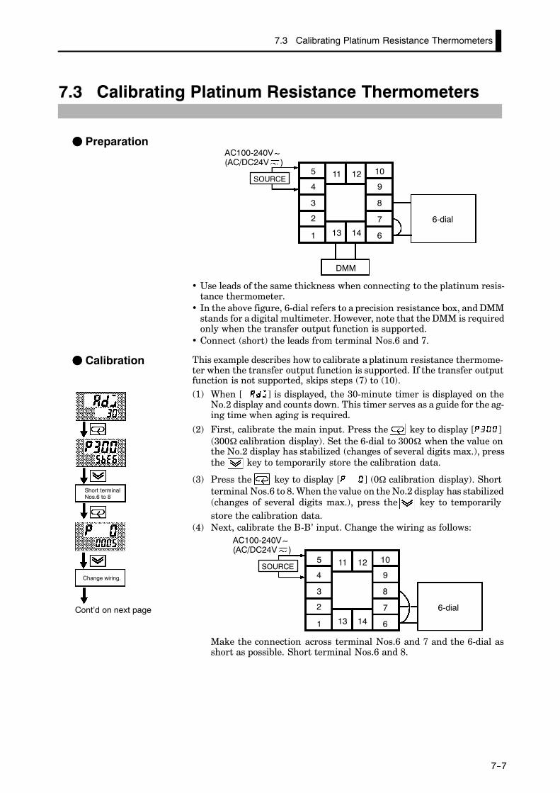
7.3 Calibrating Platinum Resistance Thermometers
7--7
7.3 Calibrating Platinum Resistance Thermometers
FF PreparationAC100-240V(AC/DC24V )
~
10
9
8
7
6
5
4
3
2
1 1413
1211
DMM
6-dial
SOURCE
• Use leads of the same thickness when connecting to the platinum resis-tance thermometer.
• In the above figure, 6-dial refers to a precision resistance box, and DMMstands for a digital multimeter. However, note that the DMM is requiredonly when the transfer output function is supported.
• Connect (short) the leads from terminal Nos.6 and 7.
This example describes how to calibrate a platinum resistance thermome-ter when the transfer output function is supported. If the transfer outputfunction is not supported, skips steps (7) to (10).(1) When [ ] is displayed, the 30-minute timer is displayed on the
No.2 display and counts down. This timer serves as a guide for the ag-ing time when aging is required.
(2) First, calibrate the main input. Press the key to display [ ](300Ω calibration display). Set the 6-dial to 300Ω. when the value onthe No.2 display has stabilized (changes of several digits max.), pressthe key to temporarily store the calibration data.
(3) Press the key to display [ ] (0Ω calibration display). Shortterminal Nos.6 to 8. When the value on the No.2 display has stabilized(changes of several digits max.), press the key to temporarilystore the calibration data.
(4) Next, calibrate the B-B’ input. Change the wiring as follows:
10
9
8
7
6
5
4
3
2
1 1413
1211
6-dial
AC100-240V(AC/DC24V )
~
SOURCE
Make the connection across terminal Nos.6 and 7 and the 6-dial asshort as possible. Short terminal Nos.6 and 8.
FF Calibration
Cont’d on next page
Change wiring.
Short terminalNos.6 to 8

CHAPTER 7 CALIBRATION
7--8
(5) Press the key to display [ ] (10Ω calibration display). Set the6-dial to 10Ω. When the value on the No.2 display has stabilized(changes of several digits max.), press the key to temporarilystore the calibration data.
(6) Press the key to display [ ] (0Ω calibration display). Shortterminal Nos.6 to 8. When the value on the No.2 display has stabilized(changes of several digits max.), press the key to temporarilystore the calibration data.
(7) Next, calibrate the transfer output function. If the transfer outputfunction is not supported, skip to step (11). Press the key. The dis-play changes to [ ] (20 mA calibration display).
(8) Set the output to 20 mA by the or keys while monitoring the
voltage on the digital multimeter. In the example on the left, the dis-play indicates that the value two digits smaller than before calibra-tion is “20 mA”.
(9) Press the key. The display changes to [ ] (4 mA calibrationdisplay).
(10) Set the output to 4 mA by the or keys while monitoring the
voltage on the digital multimeter. In the example on the left, the dis-play indicates that the value two digits smaller than before calibra-tion is “4 mA”.
(11) Press the key until the display changes to the data store display.Press the key. The No.2 display changes to [ ], and two se-
conds later the calibration data is stored to internal memory. If youpress the key when the No.2 display reads [ ], the calibrationdata is disabled.
(12) This completes calibration of the platinum resistance thermometer.Press the key to return the display to [ ].
From previous page
Short terminalNos.6 to 8

7.4 Calibrating Current Input
7--9
7.4 Calibrating Current Input
FF Preparation
10
9
8
7
6
5
4
3
2
1 1413
1211
DMM
STV
AC100-240V(AC/DC24V )
~
SOURCE
• In the above figure, STV refers to a standard DC current/voltage source,and DMM refers to a precision digital multimeter. However, note thatthe DMM is required only when the transfer output function is sup-ported.
This example describes how to calibrate a platinum resistance thermome-ter when the transfer output function is supported. If the transfer outputfunction is not supported, skips steps (4) to (7).(1) When [ ] is displayed, the 30-minute timer is displayed on the
No.2 display and counts down. This timer serves as a guide for the ag-ing time when aging is required.
(2) Press the key. The display changes to [ ] (20 mA calibrationdisplay). Set the STV output to 20 mA. When the value on the No.2display has stabilized (changes of several digits max.), press thekey to temporarily store the calibration data.
(3) Press the key. The display changes to [ ] (0 mA calibrationdisplay). Set the STV output to 0 mA. When the value on the No.2 dis-play has stabilized (changes of several digits max.), press the keyto temporarily store the calibration data.
(4) Next, calibrate the transfer output function. If the transfer outputfunction is not supported, skip to step (8). Press the key. The dis-play changes to [ ] (20 mA calibration display).
(5) Set the output to 20 mA by the or keys while monitoring thevoltage on the digital multimeter. In the example on the left, the dis-play indicates that the value two digits smaller than before calibra-tion is “20 mA”.
(6) Press the key. The display changes to [ ] (4 mA calibrationdisplay).
(7) Set the output to 4 mA by the or keys while monitoring thevoltage on the digital multimeter. In the example on the left, the dis-play indicates that the value two digits smaller than before calibra-tion is “4 mA”.
(8) Press the key until the display changes to the data store display.Press the key. The No.2 display changes to [ ], and two se-conds later the calibration data is stored to internal memory. If youpress the key when the No.2 display reads [ ], the calibrationdata is disabled.
(9) This completes calibration of the current input. Press the key toreturn the display to [ ].
FF Calibration

CHAPTER 7 CALIBRATION
7--10
7.5 Calibrating Voltage Input
FF Preparation
10
9
8
7
6
5
4
3
2
1 1413
1211
DMM
STV
AC100-240V(AC/DC24V )
~
SOURCE
• In the above figure, STV refers to a standard DC current/voltage source,and DMM refers to a precision digital multimeter. However, note thatthe DMM is required only when the transfer output function is sup-ported.
This example describes how to calibrate a platinum resistance thermome-ter when the transfer output function is supported. If the transfer outputfunction is not supported, skips steps (4) to (7).(1) When [ ] is displayed, the 30-minute timer is displayed on the
No.2 display and counts down. This timer serves as a guide for the ag-ing time when aging is required.
(2) Press the key. The display changes to [ ] (5 V calibration dis-play). Set the STV output to 5 V. When the value on the No.2 displayhas stabilized (changes of several digits max.), press the key to
temporarily store the calibration data.
(3) Press the key. The display changes to [ ] (0 V calibration dis-play). Set the STV output to 0 V. When the value on the No.2 displayhas stabilized (changes of several digits max.), press the key to
temporarily store the calibration data.(4) Next, calibrate the transfer output function. If the transfer output
function is not supported, skip to step (8). Press the key. The dis-play changes to [ ] (20 mA calibration display).
(5) Set the output to 20 mA by the or keys while monitoring the
voltage on the digital multimeter. In the example on the left, the dis-play indicates that the value two digits smaller than before calibra-tion is “20 mA”.
(6) Press the key. The display changes to [ ] (4 mA calibrationdisplay).
(7) Set the output to 4 mA by the or keys while monitoring the
voltage on the digital multimeter. In the example on the left, the dis-play indicates that the value two digits smaller than before calibra-tion is “4 mA”.
FF Calibration:0 to 5V, 1 to 5V
Cont’d on next page

7.5 Calibrating Voltage Input
7--11
(8) Press the key until the display changes to the data store display.Press the key. The No.2 display changes to [ ], and two se-
conds later the calibration data is stored to internal memory. If youpress the [ ] key when the No.2 display reads [ ], the calibra-tion data is disabled.
(9) This completes calibration of the voltage input (0 to 5 V, 1 to 5 V).Press the key to return the display to [ ].
This example describes how to calibrate a platinum resistance thermome-ter when the transfer output function is supported. If the transfer outputfunction is not supported, skips steps (4) to (7).
(1) When [ ] is displayed, the 30-minute timer is displayed on theNo.2 display and counts down. This timer serves as a guide for the ag-ing time when aging is required.
(2) Press the key. The display changes to [ ] (10 V calibrationdisplay). Set the STV output to 10 V. When the value on the No.2 dis-play has stabilized (changes of several digits max.), press the key
to temporarily store the calibration data.
(3) Press the key. The display changes to [ ] (0 V calibration dis-play). Set the STV output to 0 V. When the value on the No.2 displayhas stabilized (changes of several digits max.), press the key to
temporarily store the calibration data.
(4) Next, calibrate the transfer output function. If the transfer output
function is not supported, skip to step (8). Press the key. The dis-play changes to [ ] (20 mA calibration display).
(5) Set the output to 20 mA by the or keys while monitoring the
voltage on the digital multimeter. In the example on the left, the dis-play indicates that the value two digits smaller than before calibra-tion is “20 mA”.
(6) Press the key. The display changes to [ ] (4 mA calibrationdisplay).
(7) Set the output to 4 mA by the or keys while monitoring the
voltage on the digital multimeter. In the example on the left, the dis-play indicates that the value two digits smaller than before calibra-tion is “4 mA”.
(8) Press the key until the display changes to the data store display.
Press the key. The No.2 display changes to [ ], and two se-
conds later the calibration data is stored to internal memory. If you
press the key when the No.2 display reads [ ], the calibrationdata is disabled.
(9) This completes calibration of the voltage input (0 to 10 V). Press the
key to return the display to [ ].
From previous page
FF Calibration:0 to 10V
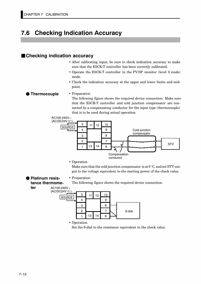
CHAPTER 7 CALIBRATION
7--12
7.6 Checking Indication Accuracy
JJChecking indication accuracy• After calibrating input, be sure to check indication accuracy to make
sure that the E5CK-T controller has been correctly calibrated.
• Operate the E5CK-T controller in the PV/SP monitor (level 0 mode)mode.
• Check the indication accuracy at the upper and lower limits and mid-point.
• PreparationThe following figure shows the required device connection. Make surethat the E5CK-T controller and cold junction compensator are con-nected by a compensating conductor for the input type (thermocouple)that is to be used during actual operation.
10
9
8
7
6
5
4
3
2
1 1413
1211
STV
Cold junctioncompensator
Compensationconductor
AC100-240V(AC/DC24V )
~
SOURCE
• OperationMake sure that the cold junction compensator is at 0_C, and set STV out-put to the voltage equivalent to the starting power of the check value.
• PreparationThe following figure shows the required device connection.
10
9
8
7
6
5
4
3
2
1 1413
1211
6-dial
AC100-240V(AC/DC24V )
~
SOURCE
• OperationSet the 6-dial to the resistance equivalent to the check value.
FF Thermocouple
FF Platinum resis-tance thermome-ter
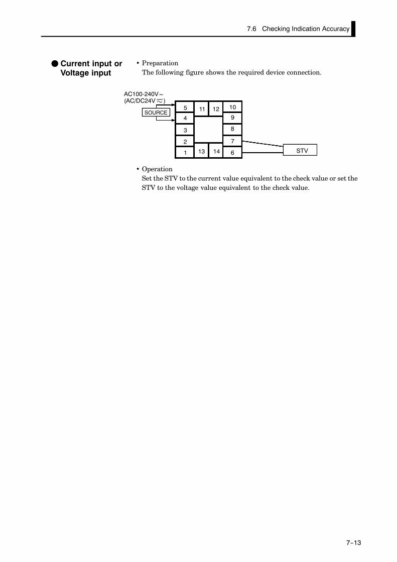
7.6 Checking Indication Accuracy
7--13
• PreparationThe following figure shows the required device connection.
10
9
8
7
6
5
4
3
2
1 1413
1211
STV
AC100-240V(AC/DC24V )
~
SOURCE
• OperationSet the STV to the current value equivalent to the check value or set theSTV to the voltage value equivalent to the check value.
FF Current input orVoltage input

CHAPTER 8 TROUBLESHOOTING
8--1
CHAPTER 8TROUBLESHOOTING
This chapter describes how to find out and remedy the cause if theE5CK-T does not function properly.Remedy E5CK-T trouble in the order of the descriptions in this chapter
CHAPTER8
8.1 Initial Checks 8-2. . . . . . . . . . . . . . . . . . . . . . . . . .
8.2 How to Use the Error Display 8-3. . . . . . . . . . .
8.3 How to Use the Error Output 8-5. . . . . . . . . . .
8.4 Checking Operation Restrictions 8-6. . . . . . . .

8--2
8.1 Initial Checks
If trouble occurs, first of all check the following:
(1) Power supply
Make sure that the power supply is ON. Also, make sure that the pow-er supply is within the rated voltage range.
(2) Input type jumper
Make sure that the input type jumper is set to the correct input type.The table below describes the operations when the jumper is not setmatched to the type of sensor connected to the input terminal.
JumperSetting Parameter Operation
TC/PT Current (0 to 20 mA) Operation is fixed at scaling lowerlimit value.
Current (4 to 20 mA)
Voltage (0 to 10 V, 0 to 5 V) Operation is fixed at scaling lowerlimit value.
Voltage (1 to 5 V)
I Temperature input
Voltage (0 10 V, 0 to 5 V) Operation is fixed at scaling lowerlimit value.
Voltage (1 to 5 V)
V Temperature input
Current (0 to 20 mA) Operation is fixed at scaling lowerlimit value.
Current (4 to 20 mA)
(3) WiringMake sure that all cables are properly connected.
(4) Communications conditions
When communicating via the RS-232C, RS-422 or RS-485 interfaces,make sure that the baud rate and other communications conditionsettings on the host computer and E5AK-T controller are matching,and are within the permissible ranges.
If there appears to be nothing wrong after checking the E5CK-T controller,and the same phenomenon continues, check the controller in more detail,
for example, on the error display.
If an error occurs during motor calibration, “ ” is displayed on the No.2 displa
The following causes of errors are possible:
• Control motor or potentiometer malfunction
• Incorrect control motor or potentiometer wiring
• Potentiometer is not connected
About Errors ThatOccur DuringMotor Calibration

8--3
8.2 How to Use the Error Display
When an error has occurred, the No.1 display alternately indicates error
codes together with the current display item.This section describes how to check error codes on the display, and the ac-tions you must take to remedy the problem.
Input error
Input is in error.
Check the wiring of inputs, disconnections, and shorts, and check the in-put type.
For control output functions, the manipulated variable matched to the set-ting of the “MV at PV error” parameter (level 2 mode) is output.Alarm output functions are activated as if the upper limit is exceeded.
Program operation is continued.
Memory error
Internal memory operation is in error.
First, turn the power OFF then back ON again. If the display remains the
same, the E5CK-T controller must be repaired. If the display is restored tonormal, then a probable cause can be external noise affecting the controlsystem. Check for external noise.
Control output functions turn OFF (2 mA max. at 4 to 20 mA output, andoutput equivalent to 0% in case of other outputs). Alarm output functionsturn OFF.
A/D converter error
Internal circuits are in error.
First, turn the power OFF then back ON again. If the display remains thesame, the E5CK-T controller must be repaired. If the display is restored to
normal, then a probable cause can be external noise affecting the controlsystem. Check for external noise.
Control output functions turn OFF (2 mA max. at 4 to 20 mA output, and
output equivalent to 0% in case of other outputs). Alarm output functionsturn OFF. Program operation is stopped.
FF Meaning
FF Action
FF Operation at er-ror
FF Meaning
FF Action
FF Operation at er-ror
FF Meaning
FF Action
FF Operation aterror

CHAPTER 8 TROUBLESHOOTING
8--4
Calibration data error
This error is output only during temperature input, and is displayed fortwo seconds when the power is turned ON.
Calibration data is in error.
E5CK-T must be repaired.
Both control output functions and alarm output functions operate. How-ever, note that readout accuracy is not assured.
Display range over
Though not an error, this is displayed when the process value exceeds thedisplay range when the control range (setting range ^10%) is larger than
the display range (-1999 to 9999).
• When less than “-1999” [ ]
• When greater than “9999” [ ]
Control continues, allowing normal operation.
If an error occurs during motor calibration, [ ] is displayed on the No.2 displa
The following causes of errors are possible:
• Control motor or potentiometer malfunction
• Incorrect control motor or potentiometer wiring
• Potentiometer is not connected
About Errors ThatOccur During Mo-tor Calibration
FF Meaning
FF Action
FF Operation aterror
FF Meaning
FF Operation

8.3 How to Use the Error Output
8--5
8.3 How to Use the Error Output
The E5CK-T controller allows you to assign error output to terminals asoutputs.
For details on output assignments, see 3.3 Setting Output Specifications(page 3-7).
• LBA (Loop Break Alarm) can be used as a means for detecting loopbreaks when the control loop is not functioning normally. For details, see4.8 LBA (page 4-16).
• LBA allows you to detect the following errors:
(1) Output error (contact weld, damaged transistors, etc.)(2) Sensor error (constant input values, etc.)
• If you use the LBA function, set the loop break detection time matchedto the control characteristics in the “LBA detection time” parameter(level 2 mode).
• If you assign error 1 as the output, an error can be output to auxiliaryoutput 1 when input is in error. When this error occurs, remedy by fol-lowing the description for “Input error”.
• If you assign error 2 as the output, an error can be output to auxiliaryoutput 1 when the A/D converter is in error. When this error occurs, rem-edy by following the description for “A/D converter error”.
FF LBA
FF Input errors
FF A/D convertererror

CHAPTER 8 TROUBLESHOOTING
8--6
8.4 Checking Operation Restrictions
With the E5CK-T controller, auto-tuning or self-tuning sometimes do notoperate depending on how functions are combined. The table below sum-
marizes the main operating restrictions.If the E5CK-T controller is not operating properly, first check whether op-erating conditions violate the restrictions in this table.
RestrictionInoperable or Invalid Functions
RestrictionAT Execution Limitter Function Other
At heating and coolingcontrol
40%AT
At ON/OFF control ¢ Manipulated variableMV change rate
At AT execution MV change rate Parameter setting
At reset ¢ Manipulated variableMV change rate
Items marked by a “x” indicate combinations of conditions that are not acceptable during AT execu-tion.

A--1
APPENDIX
SPECIFICATIONS A-2. . . . . . . . . . . . . . . . . . . . . . . . .
CONTROL BLOCK DIAGRAM A-5. . . . . . . . . . . . . .
SETTING LIST A-6. . . . . . . . . . . . . . . . . . . . . . . . . . . .
MODEL LIST A-10. . . . . . . . . . . . . . . . . . . . . . . . . . . . . .
PARAMETER OPERATIONS LIST A-11. . . . . . . . . .
ASCII CODE LIST A-13. . . . . . . . . . . . . . . . . . . . . . . . . .

A--2
SPECIFICATIONS
JJRatings
Supply voltage 100 to 240V AC, 50/60 Hz 24 VAC/DC, 50/60 Hz
Operating VoltageRange 85% to 110% of rated supply voltage
Power Consumption 15VA 6 VA, 3.5 W
Sensor Input
Thermocouple: K, J, T, E, L, U, N, R, S, B, W, PLII *1, *2Platinum resistance thermometer: JPt100, Pt100Voltage input: 4 to 20 mA, 0 to 20 mA (input impedance 150Ω)Current input: 1 to 5 V, 0 to 5 V, 0 to 10 V (input impedance 1MΩ)
Control Output According to output unit (see “Output Unit Ratings and Characteristics” (page A-4)
Auxiliary Output SPST-NO, 3 A at 250 VAC (resistive load)
Control Method Advanced PID or ON/OFF control
Setting Method Digital setting using front panel keys.
Indication Method 7-segment digital display and LEDs
Other Functions According to option unit (see “Option Unit Ratings and Characteristics” (page A-4)
Ambient Temperature -10°C to 55°C (without condensation and icing)/3-year warranty period: -10 to 50°C
Ambient Humidity 35% to 85% (relative humidity)
Storage Temperature -25°C to 65°C (without condensation and icing)
*1 Thermocouple W is W/Re5-26.*2 For the setting ranges and indication ranges for each of inputs, see page A-4.
*1, *2

A--3
JJCharacteristics
Indication Accuracy
Thermometer:(±0.3% of indication value or ±1°C, whichever greater) ±1 digit max. (*1)Platinum resistance thermometer:(±0.2% of indication value or± 0.8°C whichever greater) ±1 digit max.Analog input: ±0.2%F±S1 digit max.
Hysteresis 0.01 to 99.99%FS (in units of 0.1%FS)
Proportional Band (P) 0.1 to 999.9%FS (in units of 0.1%FS)
Integral Time (I) 0 to 3999s (in units of 1 second)
Derivative Time (D) 0 to 3999s (in units of 1 second)
Control Period 1 to 99s (in units of 1 second)
Manual Reset Value 0.0 to 100.0% (in units of 0.1%)
Alarm Setting Range -1999 to 9999 (decimal point position dependent on input type)
Sampling Period Temperature input: 250 ms, Analog input: 100 ms.
Program Method Set time or rate of rise programming
Program Size Max. 4 patterns, Max. 16 steps/pattern
Program Time Accuracy ±0.2% ±500 ms of set value (even-numbered steps in the “rate of rise program-ming” setting are set to the time unit of ramp rate)
Insulation Resistance 20 M min. (at 500 VDC)
Dielectric Strength 2000 VAC, 50/60 Hz for 1 min. (between electrically live terminals of differentpolarities)
VibrationResistance
Malfunction 10 to 55 Hz, 10m/s2 approx. 1G for 10 min. each in X, Y, and Z directionsVibrationResistance Destruction 10 to 55 Hz, 10m/s2 approx. 2G for 2 hrs. each in X, Y, and Z directions
ShockResistance
Malfunction 200 m/s2 min. approx. 20G, 3 times each in 6 directions (100 m/s2 approx.10G applied to the relay)
ResistanceDestruction 300 m/s2 min. approx. 30G, 3 times each in 6 directions
Weight Approx. 170 g, adapter: approx. 10 g
Enclosure RatingsFront panel: NEMA4 for indoor use (equivalent to IP66)Fear case: IP20Terminals: IP00
Memory Protection Non-volatile memory (number of writes: 100,000)
*1 The indication accuracy of the K1, T and N thermocouples at a temperature of -100C or less is ±2°C ±1 digit maximum. Theindication accuracy of the U, L1 and L2 thermocouples at any temperature is ±2C ±1 digit maximum.The indication accuracy of the B thermocouple at a temperature of 400°C or less is unrestricted.The indication accuracy of the R and S thermocouples at a temperature of 200°C or less is ±3°C ±1 digit maximum.The indication accuracy of the W thermocouple ±1 digit max. of whichever is the greater of ±0.3% or ±3°C of the indicatedvalue.The indication accuracy of the PLII thermocouple is ±1 digit max. of whichever is the greater of ±0.3% or ±2°C of the indi-cated value.

APPENDIX
A--4
JJSensor Input Setting Ranges and Indication Ranges
Input Setting Range Indication Range
JPt100 -199.9 to 650.0 (C°) / -199.9 to 999.9 (F°) -199.9 to 735.0 (C°) / -199.9 to 999.9 (F°)
Pt100 -199.9 to 650.0 (C°) / -199.9 to 999.9 (F°) -199.9 to 735.0 (C°) / -199.9 to 999.9 (F°)
K1 -200 to 1300 (C°) / -300 to 2300 (F°) -350 to 1450 (C°) / -560 to 2560 (F°)
K2 -0.0 to 500.0 (C°) / -0.0 to 900.0 (F°) -50.0 to 550.0 (C°) / -90.0 to 990.0 (F°)
J1 -100 to 850 (C°) / -100 to 1500 (F°) -195 to 945 (C°) / -260 to 1660 (F°)
J2 -0.0 to 400.0 (C°) / -0.0 to 750.0 (F°) -40.0 to 440.0 (C°) / -75.0 to 825.0 (F°)
T -199.9 to 400.0 (C°) / -199.9 to 700.0 (F°) -199.9 to 460.0 (C°) / -199.9 to 790.0 (F°)
E 0 to 600 (C°) / -0 to 1100 (F°) -60 to 660.0 (C°) / -110 to 1210 (F°)
L1 -100 to 850 (C°) / -100 to 1500 (F°) -195 to 945 (C°) / -260 to 1660 (F°)
L2 0.0 to 400.0 (C°) / 0.0 to 750.0 (F°) -40.0 to 440.0 (C°) / -75.0 to 825.0 (F°)
U -199.9 to 400.0 (C°) / -199.9 to 700.0 (F°) -199.9 to 650.0 (C°) / -199.9 to 999.9 (F°)
N -200.0 to 1300 (C°) / -300 to 2300 (F°) -199.9 to 460.0 (C°) / -199.9 to 790.0 (F°)
R 0 to 1700 (C°) / 0 to 3000 (F°) -350 to 1450 (C°) / -560 to 2560 (F°)
S 0 to 1700 (C°) / 0 to 3000 (F°) -170 to 1870 (C°) / -300 to 3300 (F°)
B 100 to 1800 (C°) / 300 to 3200 (F°) -170 to 1870 (C°) / -300 to 3300 (F°)
W 0 to 2300 (C°) / 0 to 4100 (F°) -70 to 1970 (C°) / 10 to 3490 (F°)
PLII 0 to 1300 (C°) / 0 to 2300 (F°) -230 to 2530 (C°) / -410 to 4510 (F°)
4 to 20mA
0 to 20mA
1 to 5V
0 to 5V
0 to 10V
One of following ranges depending onresults of scaling
-1999 to 9999
-199.9 to 999.9
-19.99 to 99.99
-1.999 to 9.999
-10 to 110% of setting range.Note, however, that max. value is -1999to 9999.
JJOutput Unit Ratings and CharacteristicsRatings and characteristics conform to the output unit mounted on the
controller. For details on the ratings of the output unit, see page 2-7.
JJOption Unit Ratings and Characteristics
Event inputsContact input ON: 1kΩ max., OFF: 100kΩ min.
Event inputsNo-contact input ON: residual voltage 1.5 V max., OFF: leakage current 0.1 mA
max.
Communications
Interface :RS-232C, RS-422 or RS-485
Transmission method :Half-duplex
Synchronization method :Start-stop synchronization (asynchronous method)
Baud rate :1.2/2.4/4.8/9.6/19.2 kbps
Transfer output DC 4 to 20 mA, Permissible load impedance: 600Ω max., Resolution: Approx.2600

CONTROL BLOCK DIAGRAM
A--5
CONTROL BLOCK DIAGRAM
SPlimitter
Program
PV
Temperatureinput
Digital filter
Input shift
Analog input
Digital filter
Scaling
Input type
Control method
Control mode Control mode
ON/OFFcontrol PID control ON/OFF control
3-position control PID control
MV changerate limitter
MV changerate limitter
MV limitter MV limitter
Dead band
MV atPV error
Manual MV
MV at stop
Error
Reset
Manual
Manipulatedvariable(cool)
Manipulatedvariable(heat)
Error
Reset
Manual
Process/function
Control
Data
Heatingside
Coolingside
Heatingside
Coolingside
ResetReset

APPENDIX
A--6
SETTING LIST
Mode Parameter Name Setting Range Unit Default Remarks Setting
ProtectSecurity 0 to 6 None 1
ProtectKey protect 0/1/2/3 None 0
Manual Manual MV -5.0 to 105.0 % 0.0
Pattern No. 0 to number of patterns -1 None 0
Level 0 Hold OFF/ON None OFF At program opera-tionLevel 0
Advance OFF/ON None OFF At program opera-tion
Pattern No. 0 to number of patterns -1 None 0
Number of steps 1 to 16 None 8
toSteps 0 to 15 SP/Target SP 0 to 7 SP lower limit to SP upper limit EU 0
to Ramp rate 0 to 7 0 to 9999 *3 0
toStep 0 to 15 time/Soak time 0 to 7 0.00 to 99.59 *4 0.00
Pattern executioncount 0 to 9999 Times 1
Program Alarm value 1 -1999 to 9999 EU 0Program
Alarm value 2 -1999 to 9999 EU 0
Alarm value 3 -1999 to 9999 EU 0
Time signal 1 enabledstep 0 to 15 None 0
Time signal 1 ON time 0.00 to 99.59 *4 0.00
Time signal 1 OFFtime 0.00 to 99.59 *4 0.00
Time signal 2 enabledstep 0 to 15 None 0
Time signal 2 ON time 0.00 to 99.59 *4 0.00
Time signal 2 OFFtime 0.00 to 99.59 *4 0.00
AT Execute/Cancel OFF/ AT-1/AT-2 None OFF
Proportional band 0.1 to 999.9 %FS 10.0
Integral time 0 to 3999 sec 233
Derivative time 0 to 3999 sec 40
Cooling coefficient 0.01 to 99.99 None 1.00 At heating andcooling control
Level 1 Dead band -19.99 to 99.99 %FS 0.00 At heating andcooling control
Manual reset value 0.0 to 100.0 % 50.0
Hysteresis (heat) 0.01 to 99.99 %FS 0.10
Hysteresis (cool) 0.01 to 99.99 %FS 0.10 At heating andcooling control
Control period (heat) 1 to 99 sec 20
Control period (cool) 1 to 99 sec 20 At heating andcooling control
*2
*2
*2
*1

SETTING LIST
A--7
Mode Parameter Name Setting Range Unit Default Remarks Setting
Remote/Local RMT/LCL None LCL
Standby time 0.00 to 99.59 Hour,Min. 0.00
LBA detection time 0 to 9999 Sec 0
MV at reset -5.0 to 105.0 % 0.0
MV at PV error -5.0 to 105.0 % 0.0
MV upper limit MV lower limit +0.1 to 105.0 % 105.0
Level 2MV lower limit -5.0 to MV upper limit -0.1 % -5.0
Level 2MV change rate limitter 0.0 to 100.0 %FS 0.0
Input digital filter 0 to 9999 sec 0
Alarm 1 hysteresis 0.01 to 99.99 % 0.02
Alarm 2 hysteresis 0.01 to 99.99 % 0.02
Alarm 3 hysteresis 0.01 to 99.99 % 0.02
Input shift upper limit -199.9 to 999.9 °C/°F 0.0 Temperature input
Input shift lower limit -199.9 to 999.9 °C/°F 0.0 Temperature input
Input type 0 to 21 None 2
Scaling upper limit Scaling lower limit +1 to 9999 None 100 Analog input
Scaling lower limit -1999 to scaling upper limit -1 None 0 Analog input
Decimal point 0 to 3 None 0 Analog input
_C/_F selection _C/_F None _C Temperature input
Parameter initialize Yes/No None NO
Control output 1 assignment *7 None HEAT
Control output 2 assignment *7 None AL-1
Auxiliary output 1 assignment *8 None AL-2
Setup Alarm 1 type 1 to 11 None 2 Output assignmentneeded
Alarm 1 open in alarm N-O/N-C None N-O Output assignmentneeded
Alarm 2 type 1 to 11 None 2 Output assignmentneeded
Alarm 2 open in alarm N-O/N-C None N-O Output assignmentneeded
Alarm 3 type 1 to 11 None 2 Output assignmentneeded
Alarm 3 open in alarm N-O/N-C None N-O Output assignmentneeded
Direct/Reverse operation OR-R/OR-D None OR-R
*1 During heating and cooling control, the lower limit becomes -105.0%*2 Use “Program List” (page A-11) for the setting value of each step.*3 EU/Time unit of ramp rate*4 Program time unit*5 During heating and cooling control, the setting range becomes 0.0 to 105.0%.*6 During heating and cooling control, the setting range becomes -105.0 to 0.0%.*7 HEAT/COOL/AL-1/AL-2/AL-3/HBA/LBA/TS -1/TS-2/PEND/STG*8 AL-1/AL-2/AL-3/HBA/LBA/TS -1/TS-2/PEND/STG/S.ERR/E333
*1
*2
*5
*6
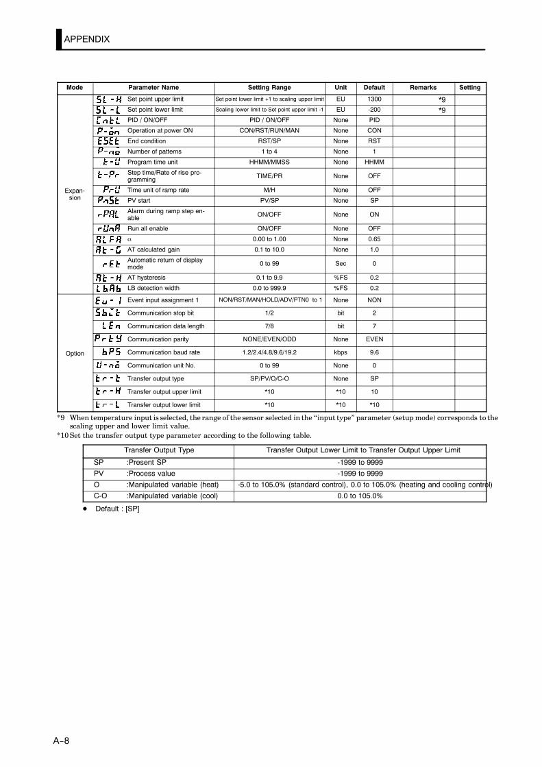
APPENDIX
A--8
Mode Parameter Name Setting Range Unit Default Remarks Setting
Set point upper limit Set point lower limit +1 to scaling upper limit EU 1300
Set point lower limit Scaling lower limit to Set point upper limit -1 EU -200
PID / ON/OFF PID / ON/OFF None PID
Operation at power ON CON/RST/RUN/MAN None CON
End condition RST/SP None RST
Number of patterns 1 to 4 None 1
Program time unit HHMM/MMSS None HHMM
Step time/Rate of rise pro-gramming TIME/PR None OFF
Expan-sion
Time unit of ramp rate M/H None OFFExpan-sion PV start PV/SP None SP
Alarm during ramp step en-able ON/OFF None ON
Run all enable ON/OFF None OFF
α 0.00 to 1.00 None 0.65
AT calculated gain 0.1 to 10.0 None 1.0
Automatic return of displaymode 0 to 99 Sec 0
AT hysteresis 0.1 to 9.9 %FS 0.2
LB detection width 0.0 to 999.9 %FS 0.2
Event input assignment 1 NON/RST/MAN/HOLD/ADV/PTN0 to 1 None NON
Communication stop bit 1/2 bit 2
Communication data length 7/8 bit 7
Communication parity NONE/EVEN/ODD None EVEN
Option Communication baud rate 1.2/2.4/4.8/9.6/19.2 kbps 9.6Option
Communication unit No. 0 to 99 None 0
Transfer output type SP/PV/O/C-O None SP
Transfer output upper limit *10 *10 10
Transfer output lower limit *10 *10 *10
*9 When temperature input is selected, the range of the sensor selected in the “input type” parameter (setup mode) corresponds to thescaling upper and lower limit value.
*10 Set the transfer output type parameter according to the following table.
Transfer Output Type Transfer Output Lower Limit to Transfer Output Upper Limit
SP :Present SP -1999 to 9999
PV :Process value -1999 to 9999
O :Manipulated variable (heat) -5.0 to 105.0% (standard control), 0.0 to 105.0% (heating and cooling control)
C-O :Manipulated variable (cool) 0.0 to 105.0%
D Default : [SP]
*9*9

SETTING LIST
A--9

APPENDIX
A--10
MODEL LIST
Description Type Name Specification
Base unit E5CK-TAA1 AC100-240 Base Unit
E5CK-TAA1-500 AC100-240 Base Unit with terminal cover
E5CK-TAA1 AC/DC24 Base Unit
E5CK-TAA1-500 AC/DC24 Base Unit with terminal cover
Output module E53-R4R4 Relay/relay
E53-Q4R4 Pulse (NPN)/relay
E53-Q4HR4 Pulse (PNP)/relay
E53-C4R4 Linear (4 to 20mA)/relay
E53-C4DR4 Linear (0 to 20mA)/relay
E53-V44R4 Linear (0 to 10V)/relay
E53-Q4Q4 Pulse (NPN)/pulse (NPN)
E53-Q4HQ4H Pulse (PNP)/pulse (PNP)
Option module E53-CK01 RS-232C
E53-CK03 RS-485
E53-CKB Event input : 1 point
E53-CKF Transfer output (4 to 20mA)
Terminal cover E53-COV07 Terminal cover for E5CK-T
The output unit is required for E5CK-TAA1 (including -500). For details on the output unit, see page 2-3.When adding on the option unit, also see the option unit list on page 2-3.

PARAMETER OPERATIONS LIST
A--11
PARAMETER OPERATIONS LIST
• Switching to modes other than the manual or protect mode is carried out by mode selection in themenu display.
• The figure below shows all parameters in the order that they are displayed. Some parameters arenot displayed depending on the protect mode setting and conditions of use.
Level 0
Program
1 second min.
Manual mode
Protect mode
Parameters in a mode can beswitched by the key. The param-eter following the last parameter is thetop parameter of the mode.
Power ON
1 second min.
1 second min.
1 second min.
1 second min.
1 second min.
1 second min.
1 second min.
1 second min.
Level 1
Level 2
Setup mode
Expansionmode
Option mode
Calibrationmode
1 second min.
1 second min.1 second min.
1 second min.
+
+
+
+
RUN/RST
RUN/RST
RUN/RST
Level 0 Program Level 1
PV/Present SP Pattern No. AT Execute/Cancel
Pattern No. Number of steps Proportional band
Step No. monitor to Step 0 to 7 SP Integral time
Hold to Ramp rate 0 to 7 Derivative time
Advance to Step 0 to 7 time Cooling coefficient
Standby time monitor to Step 8 to 15 SP Dead band
Pattern elapsing time monitor to Step 8 to 15 time Position-proportional dead band
Pattern execution count monitor Pattern execution count Manual reset value
MV monitor (heat) Alarm value 1 Hysteresis (heat)
MV monitor (cool) Alarm value 2 Hysteresis (cool)
Alarm value 3 Control period (heat)
Time signal 1 enabled step Control period (cool)
Time signal 1 ON time
Time signal 1 OFF time
Time signal 2 enabled step
Time signal 2 ON time
Time signal 2 OFF time
*1
*1
*1In the rate of rise setting, Target SP 0to 7 and Soak time 0 to 7.

APPENDIX
A--12
Level 2 Setup Expansion
Remote/Local Input type Set point upper limit
Standby time Scaling upper limit Set point lower limit
LBA detection time Scaling lower limit PID / ON/OFF
MV at reset Decimal point Operation at power ON
MV at PV error °C/°F selection End condition
MV upper limit Parameter initialize Number of patterns
MV lower limit Control output 1 assignment Program time unit
MV change rate limit Control output 2 assignment Step time/Rate of rise programming
Input digital filter Auxiliary output 1 assignment Time unit of ramp rate
Alarm 1 hysteresis Alarm 1 type PV start
Alarm 2 hysteresis Alarm 1 open in alarm Alarm during ramp step enable
Alarm 3 hysteresis Alarm 2 type Run all enable
Input shift upper limit Alarm 2 open in alarm α
Input shift lower limit Alarm 3 type AT calculated gain
Alarm 3 open in alarm Automatic return of display mode
Direct/Reverse operation AT hysteresis
LBA detection width
Option Calibration
Event input assignment 1 For details, refer to Chapter 7 Calibra-tion/7.1 Structure of Parameters” (page
Communication stop bittion/7.1 Structure of Parameters” (page7-2).
Communication data length ManualCommunication parity
Manual
Communication baud rate Manual MV
Communication unit No.
Transfer output type ProtectTransfer output upper limit
Protect
Transfer output lower limit Alarm 1 open in alarm
Alarm 2 type

ASCII CODE LIST
A--13
ASCII CODE LIST
Hex 0 1 2 3 4 5 6 7
Bin 0000 0001 0010 0011 0100 0101 0110 0111
0 0000 SP 0 @ P p
1 0001 ! 1 A Q a q
2 0010 ” 2 B R b r
3 0011 # 3 C S c s
4 0100 $ 4 D T d t
5 0101 % 5 E U e u
6 0110 & 6 F V f v
7 0111 ’ 7 G W g w
8 1000 ( 8 H X h x
9 1001 ) 9 I Y i y
A 1010 * : J Z j z
B 1011 + ; K [ k
C 1100 , < L ¥ l |
D 1101 - = M ] m
E 1110 . > N ^ n ~
F 1111 / ? O _ o DEL
Upper 4 bits
Lower 4 bits

INDEX
Symbols
° C/° F selection 5---31. . . . . . . . . . . . . . . . . . . .
Numbers
100%AT 3---24. . . . . . . . . . . . . . . . . . . . . . . . . .40%AT 3---24. . . . . . . . . . . . . . . . . . . . . . . . . . . .
A
A group 6---11. . . . . . . . . . . . . . . . . . . . . . . . . . .A/D converter error 8---3, 8---5. . . . . . . . . . . . .A/M key 1---4. . . . . . . . . . . . . . . . . . . . . . . . . . . .About Calibration 1---12. . . . . . . . . . . . . . . . . .About Changing the Number of Steps 3---21About Errors That Occur During Motor
Calibration 8---4. . . . . . . . . . . . . . . . . . . . . .About invalid parameters 6---5. . . . . . . . . . . .About ON conditions 4---13. . . . . . . . . . . . . . .About parameter display 5---2. . . . . . . . . . . . .About Pattern Elapsing Time 4---13. . . . . . .About PID Parameters 3---25. . . . . . . . . . . . .About Reset 4---12. . . . . . . . . . . . . . . . . . . . . . .About the Alarm Value Decimal Point 3---15About the Communications Function 1---11About the displays 1---3. . . . . . . . . . . . . . . . . .About the Order in Which Parameters
Described in This Chapter 5---2. . . . . . . . .About the Unit No. 6---15. . . . . . . . . . . . . . . . .Advance 4---18, 5---8. . . . . . . . . . . . . . . . . . . . .Alarm 1 hysteresis 5---26. . . . . . . . . . . . . . . . .Alarm 1 open in alarm 5---35. . . . . . . . . . . . . .Alarm 1 type 5---34. . . . . . . . . . . . . . . . . . . . . .Alarm 2 hysteresis 5---26. . . . . . . . . . . . . . . . .Alarm 2 open in alarm 5---35. . . . . . . . . . . . . .Alarm 2 type 5---34. . . . . . . . . . . . . . . . . . . . . .Alarm 3 hysteresis 5---26. . . . . . . . . . . . . . . . .Alarm 3 open in alarm 5---35. . . . . . . . . . . . . .Alarm 3 type 5---34. . . . . . . . . . . . . . . . . . . . . .Alarm hysteresis 3---10. . . . . . . . . . . . . . . . . . .Alarm type 3---9. . . . . . . . . . . . . . . . . . . . . . . . .Alarm value 3---9, 3---15. . . . . . . . . . . . . . . . . .Alarm value 1 5---14. . . . . . . . . . . . . . . . . . . . .Alarm value 2 5---14. . . . . . . . . . . . . . . . . . . . .Alarm value 3 5---14. . . . . . . . . . . . . . . . . . . . .Alfa 5---42. . . . . . . . . . . . . . . . . . . . . . . . . . . . . .Analog input 3---5. . . . . . . . . . . . . . . . . . . . . . .ASCII CODE LIST A---13. . . . . . . . . . . . . . . . .AT Execute/Cancel 5---18. . . . . . . . . . . . . . . . .AT Execution Timing 3---25. . . . . . . . . . . . . .Auto---tuning (A.T.) 3---24. . . . . . . . . . . . . . . .Auto---turning key 1---4. . . . . . . . . . . . . . . . . .Auto/Manual 4---18. . . . . . . . . . . . . . . . . . . . . .
Auxiliary output 1 2---8. . . . . . . . . . . . . . . . . .Auxiliary output 1 assignment 5---33. . . . . . .
B
B group 6---11. . . . . . . . . . . . . . . . . . . . . . . . . . .Balance---less, Bump---less Operation 3---23.Basic Operation Flow 3---2. . . . . . . . . . . . . . . .
C
Cable connections 6---3. . . . . . . . . . . . . . . . . . .Calibrating Current Input 7---9. . . . . . . . . . .Calibrating inputs 1---12. . . . . . . . . . . . . . . . .Calibrating Platinum Resistance
Thermometers 7---7. . . . . . . . . . . . . . . . . . .Calibrating Thermocouples 7---4. . . . . . . . . .Calibrating transfer output 1---12. . . . . . . . .Calibrating Voltage Input 7---10. . . . . . . . . . .Calibration 7---7, 7---9. . . . . . . . . . . . . . . . . . . . .Calibration data error 8---4. . . . . . . . . . . . . . .Calibration item menu 7---3. . . . . . . . . . . . . .Calibration Mode 1---9. . . . . . . . . . . . . . . . . . .Calibration: 0 to 10V 7---11. . . . . . . . . . . . . . .Calibration: 0 to 5V, 1 to 5V 7---10. . . . . . . . .Calibration: thermocouple 1 7---5. . . . . . . . . .Calibration: thermocouple 2 7---6. . . . . . . . . .Changing parameters 4---8. . . . . . . . . . . . . . . .Changing programs 3---21. . . . . . . . . . . . . . . .Changing the SP 3---21. . . . . . . . . . . . . . . . . . .Changing the time value 3---21. . . . . . . . . . . .Characteristics A---3. . . . . . . . . . . . . . . . . . . . .Checking Indication Accuracy 7---12. . . . . . .Checking indication accuracy 7---12. . . . . . . .Checking Operation Restrictions 8---6. . . . .Close in alarm/open in alarm 3---10. . . . . . . .Command Structure 6---5. . . . . . . . . . . . . . . . .Commands and Responses 6---7. . . . . . . . . . .Communication baud rate 5---46. . . . . . . . . .Communication data length 5---46. . . . . . . . .Communication parity 5---46. . . . . . . . . . . . . .Communication stop bit 5---46. . . . . . . . . . . .Communication unit No. 5---46. . . . . . . . . . . .Communications parameters 6---4. . . . . . . . .Conditions when running a program 6---17.Connecting the Cold Junction
Compensator 7---4. . . . . . . . . . . . . . . . . . . .CONTROL BLOCK DIAGRAM A---5. . . . . . .Control output 2---7. . . . . . . . . . . . . . . . . . . . . .Control output 1 assignment 5---32. . . . . . . .Control output 2 assignment 5---32. . . . . . . .Control period 3---8. . . . . . . . . . . . . . . . . . . . . .Control period (cool) 5---21. . . . . . . . . . . . . . .Control period (heat) 5---21. . . . . . . . . . . . . . .

INDEX
Convention Used in this Chapter 3---2. . . . .Conventions Used in this Chapter 5---2. . . .Cooling coefficient 4---2, 5---19. . . . . . . . . . . .Current input 1---5. . . . . . . . . . . . . . . . . . . . . .Current input or Voltage input 7---13. . . . . .
D
Dead band 4---2, 5---19. . . . . . . . . . . . . . . . . . . .Decimal point 5---30. . . . . . . . . . . . . . . . . . . . .Derivative time 5---18. . . . . . . . . . . . . . . . . . . .Detailed description of input functions 4---18Determining the LBA detection time 4---20.Dimensions 2---4. . . . . . . . . . . . . . . . . . . . . . . .Direct/Reverse operation 3---7, 5---35. . . . . . .Display range over 8---4. . . . . . . . . . . . . . . . . .Down key 1---4. . . . . . . . . . . . . . . . . . . . . . . . . .Draw---out 2---2. . . . . . . . . . . . . . . . . . . . . . . . . .
E
End code 6---15. . . . . . . . . . . . . . . . . . . . . . . . . .End condition 4---16, 5---38. . . . . . . . . . . . . . .Event input 1---5. . . . . . . . . . . . . . . . . . . . . . . .Event input assignment 1 5---45. . . . . . . . . . .Examples of use 6---19. . . . . . . . . . . . . . . . . . . .Executing all patterns 4---11. . . . . . . . . . . . . .Expansion Mode 1---9, 5---36. . . . . . . . . . . . . .
F
Fixing settings 1---10. . . . . . . . . . . . . . . . . . . . .Front panel 1---2. . . . . . . . . . . . . . . . . . . . . . . .
H
Heating and cooling control 4---2. . . . . . . . . .Hold 5---8. . . . . . . . . . . . . . . . . . . . . . . . . . . . . . .Hold/advance 4---10. . . . . . . . . . . . . . . . . . . . . .Hold/Hold cancel 4---18. . . . . . . . . . . . . . . . . . .How the program works 4---9. . . . . . . . . . . . .How to Calculate FCS 6---6. . . . . . . . . . . . . . .How to Read Communications
Error Information 6---15. . . . . . . . . . . . . . .How to use keys 1---4. . . . . . . . . . . . . . . . . . . . .How to use programs 6---17. . . . . . . . . . . . . . .How to Use the Error Display 8---3. . . . . . . .How to Use the Error Output 8---5. . . . . . . .How to Use Transfer Output 4---21. . . . . . . .Hysteresis 4---4. . . . . . . . . . . . . . . . . . . . . . . . . .Hysteresis (cool) 5---20. . . . . . . . . . . . . . . . . . .Hysteresis (heat) 5---20. . . . . . . . . . . . . . . . . . .
I
Initial Checks 8---2. . . . . . . . . . . . . . . . . . . . . . .Input 2---7. . . . . . . . . . . . . . . . . . . . . . . . . . . . . .
Input and Output 1---5. . . . . . . . . . . . . . . . . . .Input assignments 4---17. . . . . . . . . . . . . . . . .Input digital filter 5---26. . . . . . . . . . . . . . . . . .Input error 8---3. . . . . . . . . . . . . . . . . . . . . . . . .Input errors 8---5. . . . . . . . . . . . . . . . . . . . . . . .Input shift lower limit 5---27. . . . . . . . . . . . . .Input shift upper limit 5---27. . . . . . . . . . . . . .Input type 3---4, 5---29. . . . . . . . . . . . . . . . . . . .Installation 2---4. . . . . . . . . . . . . . . . . . . . . . . . .Integral time 5---18. . . . . . . . . . . . . . . . . . . . . .Interface 6---2. . . . . . . . . . . . . . . . . . . . . . . . . . .Issuing special commands 6---10. . . . . . . . . . .
K
Key protect 3---18, 5---4. . . . . . . . . . . . . . . . . . .
L
LBA 4---19, 8---5. . . . . . . . . . . . . . . . . . . . . . . . .LBA detection example 4---19. . . . . . . . . . . . .LBA detection time 4---19, 5---24. . . . . . . . . . .LBA detection width 4---19. . . . . . . . . . . . . . .Level 0 Mode 1---8, 5---6. . . . . . . . . . . . . . . . . . .Level 1 Mode 1---8, 5---17. . . . . . . . . . . . . . . . .Level 2 Mode 1---8, 5---22. . . . . . . . . . . . . . . . .Limiter operation conditions 4---6. . . . . . . . .
M
Main parts 1---2. . . . . . . . . . . . . . . . . . . . . . . . .Manipulated variable at reset 4---3. . . . . . . .Manipulated variable at stop 3---20. . . . . . . .Manipulated variable restrictions 4---5. . . . .Manual Mode 1---8, 5---5. . . . . . . . . . . . . . . . . . .Manual MV 5---5. . . . . . . . . . . . . . . . . . . . . . . .Manual reset value 5---20. . . . . . . . . . . . . . . . .Memory error 8---3. . . . . . . . . . . . . . . . . . . . . .MODEL LIST A---10. . . . . . . . . . . . . . . . . . . . .Monitor process value 6---19. . . . . . . . . . . . . .MV at PV error 5---24. . . . . . . . . . . . . . . . . . . .MV at reset 5---24. . . . . . . . . . . . . . . . . . . . . . . .MV change rate limit 5---25. . . . . . . . . . . . . . .MV change rate limiter 4---5. . . . . . . . . . . . . .MV limiter 4---5. . . . . . . . . . . . . . . . . . . . . . . . .MV lower limit 5---25. . . . . . . . . . . . . . . . . . . .MV monitor (cool) 5---10. . . . . . . . . . . . . . . . .MV monitor (heat) 5---10. . . . . . . . . . . . . . . . .MV upper limit 5---25. . . . . . . . . . . . . . . . . . . .
NNames of parts 1---2. . . . . . . . . . . . . . . . . . . . .No.1 display 1---3. . . . . . . . . . . . . . . . . . . . . . . .No.2 display 1---3. . . . . . . . . . . . . . . . . . . . . . . .Number of patterns 5---39. . . . . . . . . . . . . . . .Number of steps 3---14, 5---12. . . . . . . . . . . . .

INDEX
O
ON/OFF control 4---4. . . . . . . . . . . . . . . . . . . .Operating Condition Restrictions 4---5. . . . .Operation at Input Error 4---9. . . . . . . . . . . .Operation at power ON 4---15, 5---38. . . . . . .Operation indicator LEDs 1---3. . . . . . . . . . .Option 2---8. . . . . . . . . . . . . . . . . . . . . . . . . . . . .Option Mode 1---9, 5---44. . . . . . . . . . . . . . . . .Option Unit Ratings and
Characteristics A---4. . . . . . . . . . . . . . . . . . .Outline 6---2. . . . . . . . . . . . . . . . . . . . . . . . . . . .Outline of the Communications
Function 6---2. . . . . . . . . . . . . . . . . . . . . . . .Output 1---6. . . . . . . . . . . . . . . . . . . . . . . . . . . . .Output assignments 1---6, 3---7. . . . . . . . . . . . .Output Unit Ratings and
Characteristics A---4. . . . . . . . . . . . . . . . . . .
P
Panel cutout 2---4. . . . . . . . . . . . . . . . . . . . . . . .Parameter initialize 5---31. . . . . . . . . . . . . . . .PARAMETER OPERATIONS LIST A---11. .Parameter Structure 7---2. . . . . . . . . . . . . . . .Parameter types 1---8. . . . . . . . . . . . . . . . . . . .Parameters and Menus 1---8. . . . . . . . . . . . . .Pattern elapsing time 5---9. . . . . . . . . . . . . . . .Pattern execution count 5---14. . . . . . . . . . . .Pattern execution count monitor 5---9. . . . .Pattern No. 3---14, 5---7. . . . . . . . . . . . . . . . . . .Pattern operation 4---11. . . . . . . . . . . . . . . . . .Pattern select 4---18. . . . . . . . . . . . . . . . . . . . . .PID/ON/OFF 5---37. . . . . . . . . . . . . . . . . . . . . .Platinum resistance thermometer 7---12. . .Power supply 2---6. . . . . . . . . . . . . . . . . . . . . . .Precautions when wiring 2---6. . . . . . . . . . . .Preparation 7---7, 7---9, 7---10. . . . . . . . . . . . . .Preparations 7---4. . . . . . . . . . . . . . . . . . . . . . .Preparing for Communications 6---3. . . . . . .Procedure 6---17. . . . . . . . . . . . . . . . . . . . . . . . .Program 1---7. . . . . . . . . . . . . . . . . . . . . . . . . . .Program end 4---14. . . . . . . . . . . . . . . . . . . . . .Program Example 6---17. . . . . . . . . . . . . . . . . .Program example 4---9. . . . . . . . . . . . . . . . . . .Program list 6---18. . . . . . . . . . . . . . . . . . . . . . .Program Mode 5---11. . . . . . . . . . . . . . . . . . . . .Program mode 1---8. . . . . . . . . . . . . . . . . . . . . .Program Operation 4---10. . . . . . . . . . . . . . . .Program output 4---13, 4---14. . . . . . . . . . . . .Program structure 4---9. . . . . . . . . . . . . . . . . .Proportional band 5---18. . . . . . . . . . . . . . . . .Protect Mode 1---8, 3---18, 5---3. . . . . . . . . . . . .
PV start 4---16, 5---41. . . . . . . . . . . . . . . . . . . . .PV/Present SP 5---6. . . . . . . . . . . . . . . . . . . . . .
R
Ramp rate 0 5---13. . . . . . . . . . . . . . . . . . . . . . .Ramp rate 7 5---13. . . . . . . . . . . . . . . . . . . . . . .Ramp Rise Rate Setup Program 4---7. . . . . .Reading parameters 6---7, 6---12. . . . . . . . . . .Reading/writing parameters 6---7. . . . . . . . . .Reading/writing program
parameters 6---12. . . . . . . . . . . . . . . . . . . . .Registering calibration data 1---12. . . . . . . . .Relationship with the
number of steps 4---8. . . . . . . . . . . . . . . . . .Remote/Local 5---23. . . . . . . . . . . . . . . . . . . . . .Repeating execution of the
same pattern 4---11. . . . . . . . . . . . . . . . . . .RS---232C 1---11, 6---3. . . . . . . . . . . . . . . . . . . .RS---485 1---11, 6---3. . . . . . . . . . . . . . . . . . . . . .Run/Reset 4---18. . . . . . . . . . . . . . . . . . . . . . . . .Running the ramp rise
rate setup program 4---8. . . . . . . . . . . . . . .
S
Scaling lower limit 5---30. . . . . . . . . . . . . . . . .Scaling upper limit 5---30. . . . . . . . . . . . . . . . .Security 3---18, 5---3. . . . . . . . . . . . . . . . . . . . . .Selecting modes 1---9. . . . . . . . . . . . . . . . . . . . .Selecting parameters 1---10. . . . . . . . . . . . . . .Selecting the Control Method 4---2. . . . . . . . .Sensor Input Setting Ranges
and Indication Ranges A---4. . . . . . . . . . . .Set point limiter 4---6. . . . . . . . . . . . . . . . . . . .Set point lower limit 5---37. . . . . . . . . . . . . . .Set point upper limit 5---37. . . . . . . . . . . . . . .Set the set point to “300.0” 6---19. . . . . . . . . .Setting Alarm Type 3---9. . . . . . . . . . . . . . . . .Setting Input Specifications 3---4. . . . . . . . . .SETTING LIST A---6. . . . . . . . . . . . . . . . . . . .Setting Output Specifications 3---7. . . . . . . .Setting Patterns 3---13. . . . . . . . . . . . . . . . . . .Setting Running Conditions 4---15. . . . . . . . .Setting the communications
specifications 6---4. . . . . . . . . . . . . . . . . . . .Setting the input type jumper 2---2. . . . . . . .Setting the LBA detection time 4---20. . . . . .Setup 2---2. . . . . . . . . . . . . . . . . . . . . . . . . . . . . .Setup examples 3---3. . . . . . . . . . . . . . . . . . . . .Setup Mode 1---8, 5---28. . . . . . . . . . . . . . . . . .SPECIFICATIONS A---2. . . . . . . . . . . . . . . . . .Stage output 4---14. . . . . . . . . . . . . . . . . . . . . . .Standard type 3---7. . . . . . . . . . . . . . . . . . . . . .Standby operation 4---16. . . . . . . . . . . . . . . . .

INDEX
Standby sequence 3---10. . . . . . . . . . . . . . . . . .Standby time 5---23. . . . . . . . . . . . . . . . . . . . . .Standby time monitor 5---9. . . . . . . . . . . . . . .Start running 6---19. . . . . . . . . . . . . . . . . . . . . .Starting and Stopping Operation 3---20. . . .Starting the program run 4---16. . . . . . . . . . .Step 0 time (Step time) 5---12, 5---13. . . . . . .Step 15 SP (Step time) 5---12. . . . . . . . . . . . . .Step 15 time (Step time) 5---13. . . . . . . . . . . .Step 7 SP (Step time) 5---12. . . . . . . . . . . . . . .Step 7 time (Step time) 5---13. . . . . . . . . . . . .Step 8 SP (Step time) 5---12. . . . . . . . . . . . . . .Step 8 time (Step time) 5---13. . . . . . . . . . . . .Step No. monitor 5---7. . . . . . . . . . . . . . . . . . . .Step operation 1---7. . . . . . . . . . . . . . . . . . . . . .Step SP/Step time 3---14. . . . . . . . . . . . . . . . . .Summary of alarm operations 3---11. . . . . . .Switching with Manual Operation 4---3. . . .
T
Temperature input 1---5, 3---5. . . . . . . . . . . . . .Temperature input shift 3---5. . . . . . . . . . . . .Temperature unit 3---5. . . . . . . . . . . . . . . . . . .Terminal arrangement 2---6. . . . . . . . . . . . . .The meaning of icons used
in this chapter 5---2. . . . . . . . . . . . . . . . . . .Thermocouple 7---12. . . . . . . . . . . . . . . . . . . . .
Time signal 4---13. . . . . . . . . . . . . . . . . . . . . . .Time signal 1 enabled step 5---15. . . . . . . . . .Time signal 1 OFF time 5---16. . . . . . . . . . . .Time signal 1 ON time 5---15. . . . . . . . . . . . . .Time signal 2 enabled step 5---15. . . . . . . . . .Time signal 2 OFF time 5---16. . . . . . . . . . . .Time signal 2 ON time 5---15. . . . . . . . . . . . . .Time unit of ramp rate 5---40. . . . . . . . . . . . .Transfer output 1---6. . . . . . . . . . . . . . . . . . . . .Transfer output lower limit 5---47. . . . . . . . .Transfer output scaling 4---21. . . . . . . . . . . . .Transfer output type 4---21, 5---47. . . . . . . . .Transfer output upper limit 5---47. . . . . . . . .Transfer procedure 6---2. . . . . . . . . . . . . . . . . .
U
Undefined error 6---16. . . . . . . . . . . . . . . . . . .Up key 1---4. . . . . . . . . . . . . . . . . . . . . . . . . . . . .Using Event Input 3---20. . . . . . . . . . . . . . . . .
V
Voltage input 1---5. . . . . . . . . . . . . . . . . . . . . . .
W
When the rate of rise is set to “0”, 4---8Wiring 2---6. . . . . . . . . . . . . . . . . . . . . . . . . . . . .Wiring Terminals 2---6. . . . . . . . . . . . . . . . . . .Writing parameters 6---7, 6---1. . . . . . . . . . . . .

Revision History
A manual revision code appears as a suffix to the catalog number on the front cover of the manual.
Cat. No. H090-E1-1
Revision code
The following table outlines the changes made to the manual during each revision. Page numbers referto previous version.
Revision code Date Revised content
1 September 1997 Original Production