Embed Size (px)
Citation preview

USER´S MANUAL
Digital ControllerE5CK
Cat. No. H078-E1-03D
I
Thank you for your purchase of your E5CK compact, intelligent digital controller.The E5CK allows the user to carry out the following:
• Select from many types of temperature and analog input (multiple input)
• Select output functions such as control output or alarm (output assignment)
•Use two setpoints (multi-SP function)
•Monitor the control loop by LBA (Loop Break Alarm)
•Use the communications function
• Calibrate input or transfer output
• It also features a watertight construction (NEMA4: equivalent to IP66)
ThisUser’sManual describes how touse theE5CK compact, high-function digital con-troller.Before using your E5CK, thoroughly read and understand this manual in order toensure correct use.
About this manual
E OMRON, 1995(1) All rights reserved. No part of this publication may be reproduced, stored in a retrieval system, or transmitted,
in any form, or by anymeans,mechanical, electronic, photocopying, recording, recording, or otherwise,withoutthe prior written permission of OMRON.
(2) No patent liability is assumed with respect to the use of the information contained herein.(3) Moreover, because OMRON is constantly striving to improve its high-quality products, the information in this
manual is subject to change without notice. Every precaution has been taken in the preparation of this manual.Nevertheless, OMRON assumes no responsibility for errors or omissions. Neither is any liability assumed fordamages resulting from the use of the information contained in this publication.
Preface
II
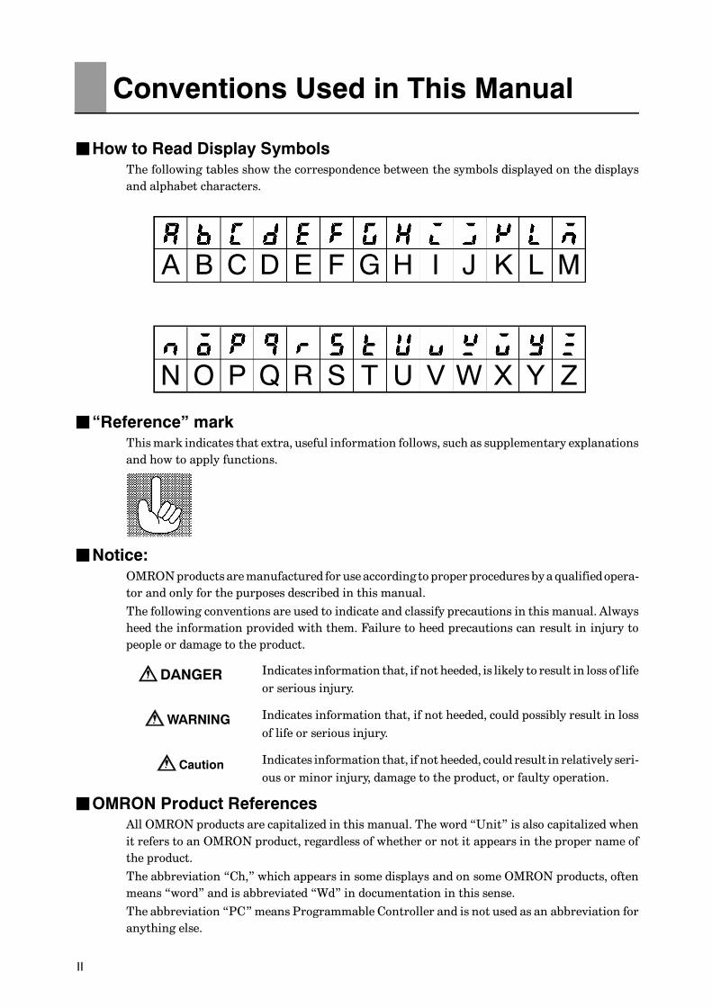
JHow to Read Display SymbolsThe following tables show the correspondence between the symbols displayed on the displaysand alphabet characters.
A B C D E F G H I J K L M
N O P Q R S T U V W X Y Z
J“Reference” markThismark indicates that extra, useful information follows, such as supplementary explanationsand how to apply functions.
JNotice:OMRONproducts aremanufactured for use according to properprocedures bya qualifiedopera-tor and only for the purposes described in this manual.
The following conventions are used to indicate and classify precautions in this manual. Alwaysheed the information provided with them. Failure to heed precautions can result in injury topeople or damage to the product.
Indicates information that, if not heeded, is likely to result in loss of lifeor serious injury.
Indicates information that, if not heeded, could possibly result in lossof life or serious injury.
Indicates information that, if not heeded, could result in relatively seri-ous or minor injury, damage to the product, or faulty operation.
JOMRON Product ReferencesAll OMRON products are capitalized in this manual. The word “Unit” is also capitalized whenit refers to an OMRON product, regardless of whether or not it appears in the proper name ofthe product.
The abbreviation “Ch,” which appears in some displays and on some OMRON products, oftenmeans “word” and is abbreviated “Wd” in documentation in this sense.
The abbreviation “PC”means Programmable Controller and is not used as an abbreviation foranything else.
Conventions Used in This Manual
DANGER
WARNING
Caution

III
JHow this Manual is Organized
Purpose Title Description
Learning about the gen-eral features of the E5CK
Chapter 1 Introduction This chapter describes the fea-tures of the E5CK, names ofparts, and typical functions.
Setting up the E5CK Chapter 2 Preparations This chapter describes the opera-tions that you must carry out(e.g. installation, wiring andswitch settings) before you canuse the E5CK.
Basic E5CK operations Chapter 3 Basic OperationChapter 5 Parameters
These chapters describe how touse the front panel keys and howto view the display when settingtheparametersof themajor func-tions for the E5CK.
Applied E5CK operations Chapter 4 Applied OperationChapter 5 Parameters
These chapters describe theimportant functions of theE5CKand how to use the parametersfor making full use of the E5CK.
Communications with ahost computer
Chapter 6 Using theCommu-nications Function
This chapter mainly describesthe communications commands,and gives program examples.
Calibration Chapter 4 Applied Operation/ 4.5 Calibration
This chapter describes how theuser should calibrate the E5CK.
Troubleshooting Chapter 7 Troubleshooting This chapter describeswhat todoif any problems occur.

IV
F If you remove the controller from its case, never touch nor apply shock to the electronicparts inside.
FDo not cover the top and bottom of the controller. (Ensure sufficient space around thecontroller to allow heat to escape.)
FUse a voltage (AC100-240V or AC/DC24V at 50 to 60 Hz). At power ON, the pre-scribed voltage level must be attained within two seconds.
FWhenwiring input or output lines to your controller, keep the following points inmindto reduce the influence from inductive noise:
• Allow adequate space between the high voltage/current power lines and the input/out-put lines.
• Avoid parallel or common wiring with high voltage sources and power lines carryinglarge currents.
• Using separating pipes, duct, and shielded line is alsouseful inprotecting thecontroller,and its lines form inductive noise.
F Allowasmuch space as possible between the controller anddevices thatgenerate apow-erful, high frequency (high-frequencywelders, high-frequency sewingmachines, and soforth) or surge. These devices may cause malfunctions.
F If there is a largepower-generating peripheral device andany of its lines, attach a surgesuppressor or noise filter to the device to stop the noise affecting the controller system.In particular, motors, transformers, solenoids and magnetic coils have an inductancecomponent, and therefore can generate very strong noises.
FWhen mounting a noise filter, be sure to first check the filter’s voltage and currentcapacity, then mount the filter as close as possible to the controller.
FDo not use the controller in placeswhere icing, condensation, dust, corrosive gas (espe-cially sulfurized gas or ammonia gas), shock, vibration, splashing liquid, or oil atmo-sphere occur. Also, avoid places where the controller can be subjected to intense heatradiation (like from a furnace) or sudden temperature changes.
F Ambient temperaturemust be kept between -10_C to 55_C. Ambient humidity must bekept between 35%RH to 85%RH (with no icing or condensation). If the controller isinstalled inside a control board, the ambient temperature must be kept under 55_C,including the temperature around the controller. If the controller is subjected to heatradiation, use a fan to cool the surface of the controller to under 55_C.
F Store the controller at an ambient temperature between -25_C to 65_C. The ambienthumidity must be between 35%RH to 85%RH (with no icing or condensation).
FNever place heavy objects on, or apply pressure to the controller that may cause it todeform and deterioration during use or storage.
F Avoid using the controller in places near a radio, television set, or wireless installation.These devices can cause radio disturbances which adversely affect the performance ofthe controller.
Pay Attention to the Following when Installingthis Controller

Preface I. . . . . . . . . . . . . . . . . . . . . . . . . . . . . . . . . . . . . .Conventions Used in This Manual II. . . . . . . . . . . . . . .Pay Attention to the Following when Installingthis Controller IV. . . . . . . . . . . . . . . . . . . . . . . . . . . . . . . . .
CHAPTER 1 INTRODUCTION 1--1. . . . . . . . . . . . . . . . . . . . . . . . . .This chapter introduces the E5CK. First-time users should read this chapter with-out fail.For details on how to use the controller and parameter settings, see Chapters 2onwards.
1.1 Names of parts 1--2. . . . . . . . . . . . . . . . . . . . . . . . . . . . . . . . . . . . . . . . . .1.2 Input and Output 1--4. . . . . . . . . . . . . . . . . . . . . . . . . . . . . . . . . . . . . . . . .1.3 Parameters and Menus 1--6. . . . . . . . . . . . . . . . . . . . . . . . . . . . . . . . . . .1.4 About the Communications Function 1--9. . . . . . . . . . . . . . . . . . . . . . .1.5 About Calibration 1--10. . . . . . . . . . . . . . . . . . . . . . . . . . . . . . . . . . . . . . . .
CHAPTER 2 PREPARATIONS 2--1. . . . . . . . . . . . . . . . . . . . . . . . . .This chapter describes the operations you should carry out before turning theE5CK ON.
2.1 Setting up 2--2. . . . . . . . . . . . . . . . . . . . . . . . . . . . . . . . . . . . . . . . . . . . . . .2.2 Installation 2--4. . . . . . . . . . . . . . . . . . . . . . . . . . . . . . . . . . . . . . . . . . . . . .2.3 Wiring Terminals 2--6. . . . . . . . . . . . . . . . . . . . . . . . . . . . . . . . . . . . . . . . .
CHAPTER 3 BASIC OPERATION 3--1. . . . . . . . . . . . . . . . . . . . . . . .This chapter describes an actual example for understanding the basic operationof the E5CK.
3.1 Control Example 3--2. . . . . . . . . . . . . . . . . . . . . . . . . . . . . . . . . . . . . . . . .3.2 Setting Input Specifications 3--3. . . . . . . . . . . . . . . . . . . . . . . . . . . . . . .3.3 Setting Output Specifications 3--5. . . . . . . . . . . . . . . . . . . . . . . . . . . . . .3.4 Setting Alarm Type 3--7. . . . . . . . . . . . . . . . . . . . . . . . . . . . . . . . . . . . . . .3.5 Protect Mode 3--10. . . . . . . . . . . . . . . . . . . . . . . . . . . . . . . . . . . . . . . . . . . .3.6 Starting and Stopping Operation 3--11. . . . . . . . . . . . . . . . . . . . . . . . . . .3.7 Adjusting Control Operation 3--12. . . . . . . . . . . . . . . . . . . . . . . . . . . . . . .
CHAPTER 4 APPLIED OPERATION 4--1. . . . . . . . . . . . . . . . . . . . .This chapter describes each of the parameters required for making full use of thefeatures of the E5CK. Read this chapter while referring to the parameter descrip-tions in chapter 5.
4.1 Selecting the Control Method 4--2. . . . . . . . . . . . . . . . . . . . . . . . . . . . . .4.2 Operating Condition Restrictions 4--4. . . . . . . . . . . . . . . . . . . . . . . . . . .4.3 How to Use Option Functions 4--7. . . . . . . . . . . . . . . . . . . . . . . . . . . . .4.4 LBA 4--9. . . . . . . . . . . . . . . . . . . . . . . . . . . . . . . . . . . . . . . . . . . . . . . . . . . .4.5 Calibration 4--11. . . . . . . . . . . . . . . . . . . . . . . . . . . . . . . . . . . . . . . . . . . . . .
Table of Contents

CHAPTER 5 PARAMETERS 5--1. . . . . . . . . . . . . . . . . . . . . . . . . . . .This chapter describes the parameters of the E5CK. Use this chapter as a refer-ence guide.
Conventions Used in this Chapter 5--2. . . . . . . . . . . . . . . . . . . . . . . . . . . . . .Protect Mode 5--3. . . . . . . . . . . . . . . . . . . . . . . . . . . . . . . . . . . . . . . . . . . . . . . .Manual Mode 5--5. . . . . . . . . . . . . . . . . . . . . . . . . . . . . . . . . . . . . . . . . . . . . . . .Level 0 Mode 5--6. . . . . . . . . . . . . . . . . . . . . . . . . . . . . . . . . . . . . . . . . . . . . . . .Level 1 Mode 5--9. . . . . . . . . . . . . . . . . . . . . . . . . . . . . . . . . . . . . . . . . . . . . . . .Level 2 Mode 5--15. . . . . . . . . . . . . . . . . . . . . . . . . . . . . . . . . . . . . . . . . . . . . . . .Setup Mode 5--21. . . . . . . . . . . . . . . . . . . . . . . . . . . . . . . . . . . . . . . . . . . . . . . . .Expansion Mode 5--27. . . . . . . . . . . . . . . . . . . . . . . . . . . . . . . . . . . . . . . . . . . . .Option Mode 5--32. . . . . . . . . . . . . . . . . . . . . . . . . . . . . . . . . . . . . . . . . . . . . . . . .Calibration Mode 5--36. . . . . . . . . . . . . . . . . . . . . . . . . . . . . . . . . . . . . . . . . . . . .
CHAPTER 6 USING THE COMMUNICATIONS FUNCTION 6--1.This chapter mainly describes communications with a host computer and com-munications commands.
6.1 Outline of the Communications Function 6--2. . . . . . . . . . . . . . . . . . . .6.2 Preparing for Communications 6--3. . . . . . . . . . . . . . . . . . . . . . . . . . . .6.3 Command Configuration 6--5. . . . . . . . . . . . . . . . . . . . . . . . . . . . . . . . . .6.4 Commands and Responses 6--6. . . . . . . . . . . . . . . . . . . . . . . . . . . . . . .6.5 How to Read Communications Error Information 6--10. . . . . . . . . . . . .6.6 Program Example 6--12. . . . . . . . . . . . . . . . . . . . . . . . . . . . . . . . . . . . . . .
CHAPTER 7 TROUBLESHOOTING 7--1. . . . . . . . . . . . . . . . . . . . . .This chapter describes how to find out and remedy the cause if the E5CK doesnot function properly.
7.1 Initial Checks 7--2. . . . . . . . . . . . . . . . . . . . . . . . . . . . . . . . . . . . . . . . . . . .7.2 How to Use the Error Display 7--3. . . . . . . . . . . . . . . . . . . . . . . . . . . . . .7.3 How to Use Error Output 7--5. . . . . . . . . . . . . . . . . . . . . . . . . . . . . . . . . .7.4 Checking Operation Restrictions 7--6. . . . . . . . . . . . . . . . . . . . . . . . . . .
APPENDIXSPECIFICATIONS A--2. . . . . . . . . . . . . . . . . . . . . . . .CONTROL BLOCK DIAGRAM A--5. . . . . . . . . . . . . .SETTING LIST A--6. . . . . . . . . . . . . . . . . . . . . . . . . . .PARAMETER OPERATIONS LIST A--8. . . . . . . . . .FUZZY SELF--TUNING A--10. . . . . . . . . . . . . . . . . . . .MODEL LIST A--13. . . . . . . . . . . . . . . . . . . . . . . . . . . . .X FORMAT A--14. . . . . . . . . . . . . . . . . . . . . . . . . . . . . . .ASCII CODE LIST A--17. . . . . . . . . . . . . . . . . . . . . . . .
INDEXREVISION HISTORY
CHAPTER 1 INTRODUCTION
1--1
CHAPTER 1INTRODUCTION
This chapter introduces the E5CK. First-time users should read thischapter without fail.For details on how to use the controller and parameter settings, seeChapters 2 onwards.
CHAPTER1
1.1 Names of parts 1---2. . . . . . . . . . . . . . . . . . . . . . . .
Main parts 1---2. . . . . . . . . . . . . . . . . . . . . . . . . . . .
Front panel 1---2. . . . . . . . . . . . . . . . . . . . . . . . . . .
About the displays 1---3. . . . . . . . . . . . . . . . . . . . .
How to use keys 1---3. . . . . . . . . . . . . . . . . . . . . . .
1.2 Input and Output 1---4. . . . . . . . . . . . . . . . . . . . . .
Input 1---4. . . . . . . . . . . . . . . . . . . . . . . . . . . . . . . . .
Output 1---5. . . . . . . . . . . . . . . . . . . . . . . . . . . . . . . .
1.3 Parameters and Menus 1---6. . . . . . . . . . . . . . . . .
Parameter types 1---6. . . . . . . . . . . . . . . . . . . . . . .
Selecting modes 1---7. . . . . . . . . . . . . . . . . . . . . . . .
Selecting parameters 1---8. . . . . . . . . . . . . . . . . . .
Fixing settings 1---8. . . . . . . . . . . . . . . . . . . . . . . . .
1.4 About the Communications Function 1---9. . . .
1.5 About Calibration 1---10. . . . . . . . . . . . . . . . . . . . . .

CHAPTER 1 INTRODUCTION
E5CK
1--2
1.1 Names of parts
JMain parts
P 2-6
P 2-3
P 2-2
P 2-3
Input type jumperconnector
Option unit
Terminals
Rear case
Output unit
Front panel
JFront panel
OUT1OUT2SUB1MANUSTOPRMTAT
Operation indica-tors
A/M key
Display key Down key Up key
No.2 display
No.1 display
E5CK
PV
SV
OUT1
OUT2 MANU STOP RMT AT SUB1
AM
A/M
1.1 Names of parts
E5CK
1--3
JAbout the displays
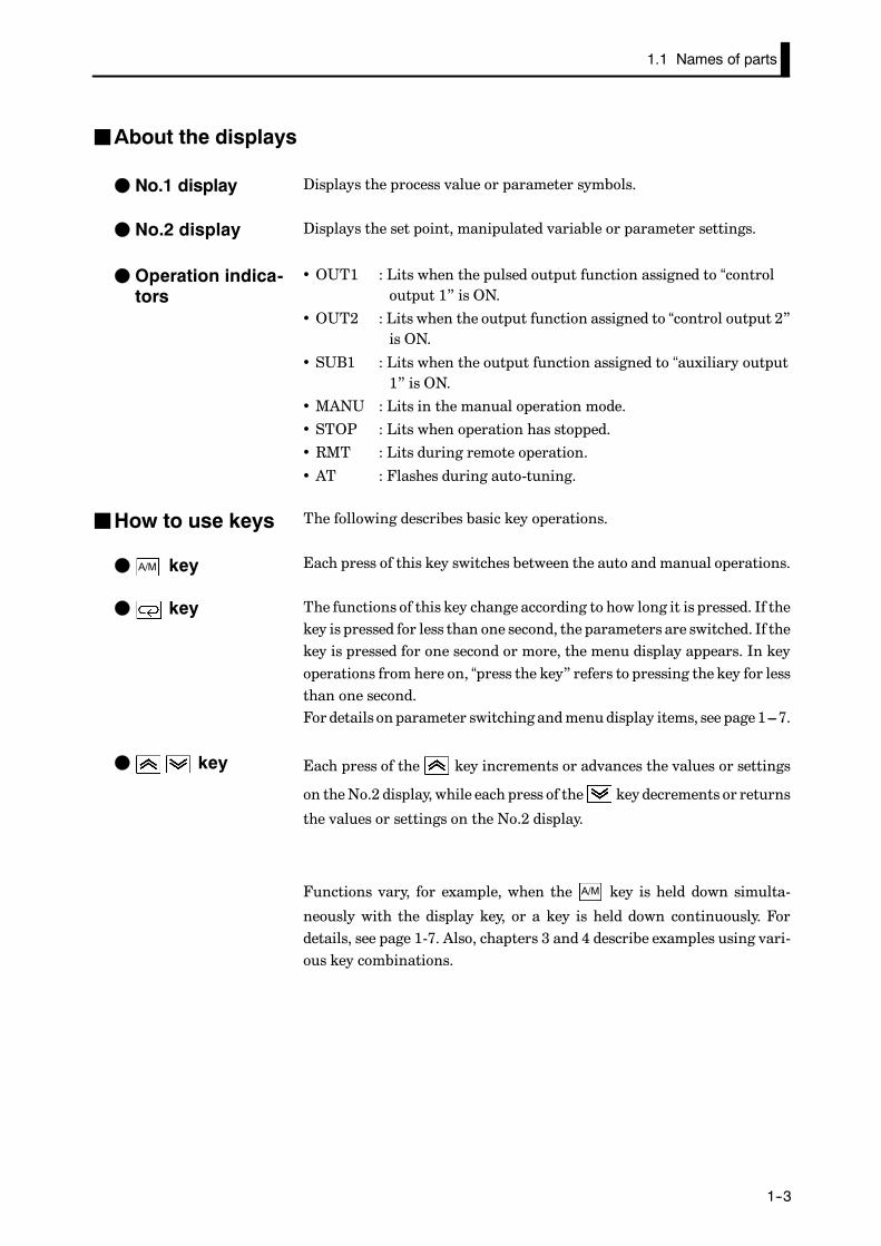
Displays the process value or parameter symbols.
Displays the set point, manipulated variable or parameter settings.
• OUT1 : Lits when the pulsed output function assigned to “controloutput 1” is ON.
• OUT2 : Lits when the output function assigned to “control output 2”is ON.
• SUB1 : Lits when the output function assigned to “auxiliary output1” is ON.
• MANU : Lits in the manual operation mode.
• STOP : Lits when operation has stopped.
• RMT : Lits during remote operation.
• AT : Flashes during auto-tuning.
The following describes basic key operations.
Each press of this key switches between the auto and manual operations.
The functions of this key change according to how long it is pressed. If thekey is pressed for less than one second, the parameters are switched. If thekey is pressed for one second or more, the menu display appears. In keyoperations from here on, “press the key” refers to pressing the key for lessthan one second.For details on parameter switching andmenudisplay items, see page1---7.
Each press of the key increments or advances the values or settings
on theNo.2 display, while each press of the key decrements or returns
the values or settings on the No.2 display.
Functions vary, for example, when the A/M key is held down simulta-
neously with the display key, or a key is held down continuously. Fordetails, see page 1-7. Also, chapters 3 and 4 describe examples using vari-ous key combinations.
F No.1 display
F No.2 display
F Operation indica-tors
JHow to use keys
F keyA/M
F key
F key
CHAPTER 1 INTRODUCTION
E5CK
1--4
1.2 Input and Output
Alarm 2
Temperatureinput
Voltage input
Current input
Event input
ControllerControl output(heat)
Control output(cool)
Alarm 1
Alarm 3
LBA
Error 1
Error 2
Control output1
Control output2
Auxiliaryoutput 1
Transferoutput 1
Input typejumper
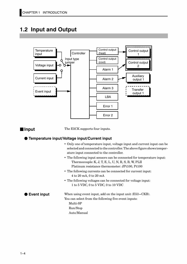
The E5CK supports four inputs.
F Temperature input/Voltage input/Current input• Only one of temperature input, voltage input and current input can beselected and connected to the controller.Theabove figure showstemper-ature input connected to the controller.
• The following input sensors can be connected for temperature input:Thermocouple:K, J, T, E, L, U, N, R, S, B, W, PLIIPlatinum resistance thermometer: JPt100, Pt100
• The following currents can be connected for current input:4 to 20 mA, 0 to 20 mA
• The following voltages can be connected for voltage input:1 to 5 VDC, 0 to 5 VDC, 0 to 10 VDC
When using event input, add on the input unit (E53---CKB).You can select from the following five event inputs:Multi-SPRun/StopAuto/Manual
J Input
F Event input

1.2 Input and Output
E5CK
1--5
JOutputThe E5CK supports the following four outputs.Control output 1Control output 2Auxiliary output 1Transfer output
When using control outputs 1 and 2, set the output unit (sold separately).Eight output units are available to suit the output circuit configuration.
Whenusing transfer output, addon the communication unit (E53---CKF).
Note: Theoutput functions of theE5CKdo not operate for five seconds af-ter the E5CK is turned ON.
The E5CK supports the following eight output functions.
Control output (heat)Control output (cool)Alarms 1 to 3LBAError 1 (input error)Error 2 (A/D converter error)
Assign these output functions to control outputs 1and2andauxiliaryout-put 1.Only control output (heat), control output (cool), alarms 1 to 3, and LBAcan be assigned to control outputs 1 and 2. Also, only alarms 1 to 3, LBA,and errors 1 and 2 can be assigned to auxiliary output 1.In the example on the previous page, “control output (heat)” is assignedto “control output 1”, “alarm 1” is assigned to “control output 2”, and“alarm 2” is assigned to “auxiliary output 1”. Accordingly, the configura-tion is such that heating control output is connected to control output 1,and alarm output is connected to control output 2 and auxiliary output 1.
In a heating and cooling control, assign “control output (cool)” to eitherof “control output 1” or “control output 2”.
The E5CK supports the following five transfer outputs.
Set pointSet point during SP rampProcess valueHeating side manipulated variableCooling side manipulated variable
These transfer outputs can be output after being scaled. Setting of anupper limit value smaller than the lower limit value is allowed, so reversescaling can also be carried out.
F Output assign-ments
F Transfer output
CHAPTER 1 INTRODUCTION
E5CK
1--6
1.3 Parameters and Menus
E5CK parameters are distributed between the following nine modes.
Protect modeManual modeLevel 0 modeLevel 1 modeLevel 2 modeSetup modeExpansion modeOption modeCalibration mode
The settings of parameters in each of seven modes (excluding the protectmode and manual mode) can be checked andmodified by selection on themenu display.
Thismode is used to limit use of themenu and A/M keys. The protect func-
tion is for preventing unwantedmodification ofparameters andswitchingbetween the auto and manual operation.
In this mode, the controller can be switched manual operation. Themanipulated variable can be manipulated manually only in this mode.
Set the controller to thismodeduring normal operation. In thismode, youmay change the set point during operation, and stop and start operation.You can alsomonitor (not change) the process value, ramp SP andmanip-ulated variable.
This is themainmode for adjusting control. In this mode, you can executeAT (auto-tuning), andsetalarmvalues, thecontrol periodandPIDparam-eters.
This is the auxiliary mode for adjusting control. In this mode, you can settheparameters for limiting themanipulatedvariable andset point, switchbetween the remote and local modes, and set the loop break alarm (LBA),alarm hysteresis and the digital filter value of inputs.
This is themode for setting the basic specifications. In thismode, you canset parameters that must be checked or set before operation such as theinput type, scaling, output assignments and direct/reverse operation.
This is themode for setting expanded functions. In this mode, you can setST (self-tuning), SP setting limiter, selection of advancedPID orON/OFFcontrol, specification of the standby sequence resettingmethod, initializa-tion of parameters, time for automatic return to the monitoring display.
JParameter types
F Protect mode
F Manual mode
F Level 0 mode
F Level 1 mode
F Level 2 mode
F Setup mode
F Expansion mode

1.3 Parameters and Menus
E5CK
1--7
This is themode for setting option functions.You can select thismodeonlywhen the option unit is set in the controller. In this mode, you can set thecommunications conditions, transfer output and event input parametersto match the type of option unit set in the controller.
This mode is provided so that the user can calibrate inputs and transferoutput.When calibrating input, the selected input type is calibrated. Whereas,transfer output can be calibrated only when the communications unit(E53---CKF) is set in the controller.
The following diagram shows the order in which modes are selected.
A/M
A/M
A/M
A/M
A/M + +
+
1 second min.
Level 0 mode
Level 1 mode
Level 2 mode
Setup mode
Expansionmode
Option mode
Calibrationmode
1 second min.
Manual mode
1 second min.
1 second min. 1 second min.
Protect mode
1 second min.
1 second min.
Power ON
1 second min.
1 second min.
1 second min.
1 second min.
1 second min.
• To select themenu display in any of the abovemodes (excluding thepro-
tect mode andmanual mode), press the key for 1 secondminimum.
If you select the desired mode using the or keys and press the
key, the top parameter in the specified mode is displayed.
• When you have selected themenu display, the previousmode is selected.For example, if you selected the menu display while in the level 0 mode,the No.2 display changes to [ ] as shown on the left.
• Protected modes cannot be selected. Also, the menu display does notappear when modes are protected up to the level 1 mode.
• If you select [ ] [ ] or [ ] in the menu display, the level 0,level 1 and level 2 modes, respectively, are selected.
• These modes are selected with control still continuing.
F Option mode
F Calibration mode
JSelecting modes
F Menu display
F Level 0 to 2modes

CHAPTER 1 INTRODUCTION
E5CK
1--8
• If you select [ ] [ ] [ ] or [ ] in the menu display, thesetup, expansion, option and calibration modes, respectively, areselected.
• When these modes are selected, the control is reset. So, control outputsand auxiliary output are turned OFF. When another mode is selectedwhile in these modes, reset is canceled.
• To set the controller to the protectmode or to return to the level 0modefrom the protectmode, press the A/M key and key for 1 secondmini-
mun simultaneously.
• To set the controller to themanual mode, press the A/M key for 1 second
minimun in the level 0 to 2 mode. To return to the level 0mode from the
manual mode, press the A/M key for 1 second minimum.
• When not in the manual mode, each press of the key switches the
parameter.
• If youpress the key when at the final parameter, the display returns
to the first parameter.
Parameter1
Parameter2
Parameter3
Parametern
• When you have changed a parameter setting, specify the parameterusing the or keys, and either leave the setting for at least two
seconds or press the key. This fixes the setting.
• When anothermode is selected, the content of theparameters before themode was selected is fixed.
• When turning the power OFF, youmust first fix the settings andparam-
eter contents (by pressing the key or selecting another mode). The
settings and parameter contents are sometimes not changed by merelypressing the or keys.
F Setup modeF Expansion modeF Option modeF Calibration mode
F Protect mode
F Manual mode
JSelectingparameters
JFixing settings
1.4 About the Communications Function
E5CK
1--9
1.4 About the Communications Function
The E5CK can be provided with a communications function that allowsyou to check and set controller parameters from a host computer. If thecommunications function is required, add on the communications unit.For details on the communications function, refer to Chapter 6.
When using the communications function on theRS---232C interface, addon the communications unit (E53---CK01).
When using the communications function on the RS---485 interface, addon the communications unit (E53---CK03).
F RS-232C
F RS-485
CHAPTER 1 INTRODUCTION
E5CK
1--10
1.5 About Calibration
The E5CK controller is calibrated before shipment from the factory. So,the user need not calibrate the E5CK controller during regular use.
However, if the E5CK controller must be calibrated by the user, use theparameters provided for user to calibrate temperature input, analog input(voltage, current) and transfer output.Also, note that calibration data is updated to the latest value each time theE5CK controller is calibrated. Calibration data set before shipment fromthe factory cannot be returned to after calibration by the user.
The input type selected in the parameter is the item to be calibrated. TheE5CK is provided with the following four calibration parameters.
• Thermocouple
• Platinum resistance thermometer
• Current input
• Voltage input
Two parameters are provided for thermocouple and voltage input.
Transfer output can be calibrated when the communications unit(E53---CKF) is added on.
When calibrating each item, the calibration data is temporarily regis-tered. This data can be registered as final calibration data only when allitems have been newly calibrated. So, all itemsmust be temporarily regis-tered when calibrating the E5CK controller.When registering data, information regarding whether or not calibrationhas been carried out is also registered.
To calibrate these items, the user must prepare separate measuringdevices and equipment. For details on handling these measuring devicesand equipment, refer to the respective manuals.
For details, see 4.5 Calibration (page 4---11).
F Calibratinginputs
F Calibrating trans-fer output
F Registering cal-ibration data

CHAPTER 2 PREPARATIONS
2--1
CHAPTER 2PREPARATIONS
This chapter describes the operations you should carry out before turn-ing the E5CK ON.
CHAPTER2
2.1 Setting up 2---2. . . . . . . . . . . . . . . . . . . . . . . . . . . . .
Draw-out 2---2. . . . . . . . . . . . . . . . . . . . . . . . . . . . . .
Setting the input type 2---2. . . . . . . . . . . . . . . . . .
Setting up the output unit 2---3. . . . . . . . . . . . . .
Setting up the option unit 2---3. . . . . . . . . . . . . . .
2.2 Installation 2---4. . . . . . . . . . . . . . . . . . . . . . . . . . . .
Dimensions 2---4. . . . . . . . . . . . . . . . . . . . . . . . . . . .
Panel cutout 2---4. . . . . . . . . . . . . . . . . . . . . . . . . . .
Mounting 2---5. . . . . . . . . . . . . . . . . . . . . . . . . . . . .
2.3 Wiring Terminals 2---6. . . . . . . . . . . . . . . . . . . . . .
Terminal arrangement 2---6. . . . . . . . . . . . . . . . .
Precautions when wiring 2---6. . . . . . . . . . . . . . .
Wiring 2---6. . . . . . . . . . . . . . . . . . . . . . . . . . . . . . . .

CHAPTER 2 PREPARATIONS
E5CK
2--2
2.1 Setting up
This section describeshow to set the input type jumper, and set up the out-put unit or option unit.
First, draw out the internal mechanism from the housing
(1) Pull out the internal mechanism while pressing the hooks on the leftand right sides of the front panel.
(2) Draw out the internal mechanism towards you holding both sides ofthe front panel.
JSetting the input type• For details on the jumper connector position, see page 1-2.• Set the input type jumper connector to oneof temperature input,voltageinput or current inputmatched to the sensor connected to the input ter-minal.
I : Current input V : Voltage input
TC.PT : Temperature input
• The factory setting is “TC/PT (temperature input).”• When removing or inserting the jumper connector, do not touch thepinsdirectly with your fingers.
• When youhave set the jumper connector, insert the internalmechanisminto the rear case.
• When inserting the internal mechanism, push in until you hear thehooks on the front panel click into place.
JDraw-out
2.1 Setting up
E5CK
2--3
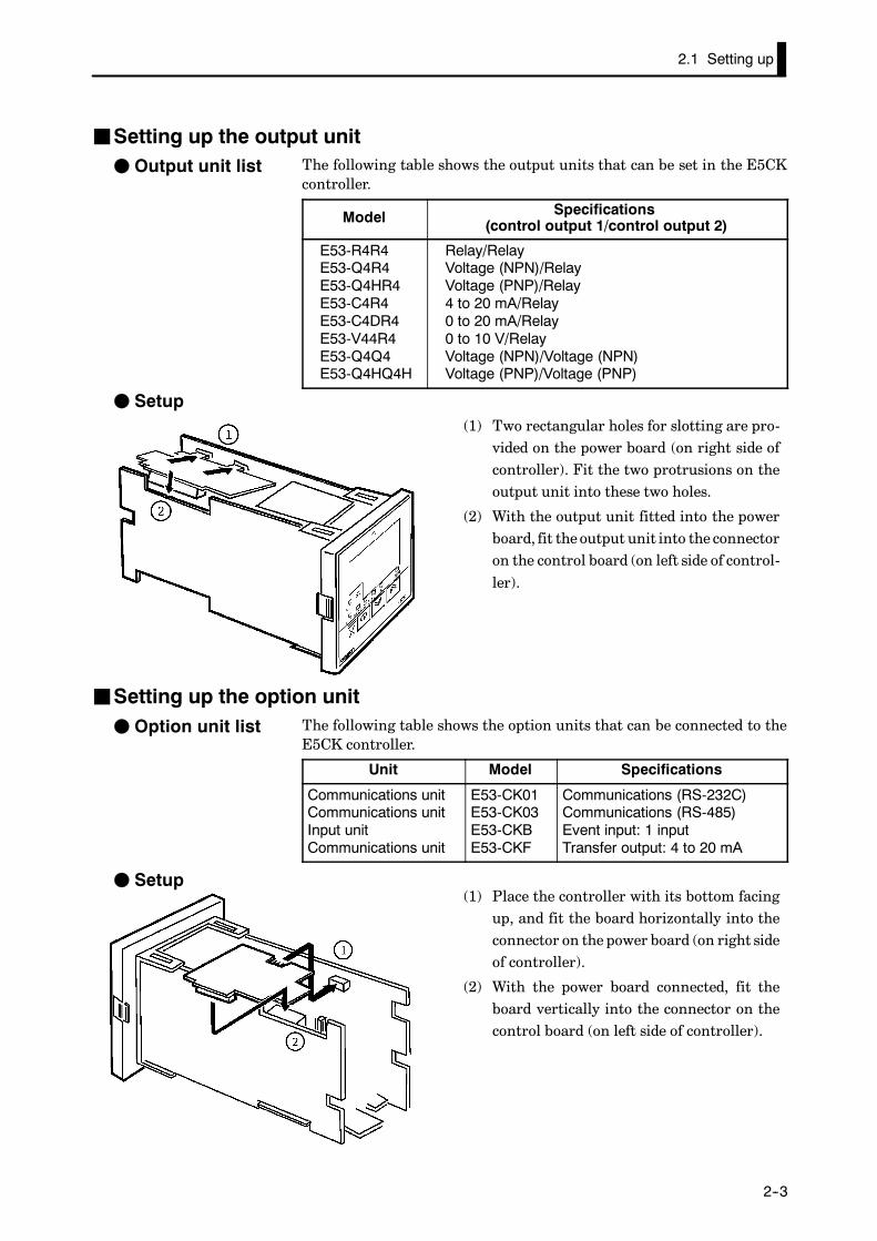
JSetting up the output unitThe following table shows the output units that can be set in the E5CKcontroller.
Model Specifications(control output 1/control output 2)
E53-R4R4E53-Q4R4E53-Q4HR4E53-C4R4E53-C4DR4E53-V44R4E53-Q4Q4E53-Q4HQ4H
Relay/RelayVoltage (NPN)/RelayVoltage (PNP)/Relay4 to 20 mA/Relay0 to 20 mA/Relay0 to 10 V/RelayVoltage (NPN)/Voltage (NPN)Voltage (PNP)/Voltage (PNP)
F Setup(1) Two rectangular holes for slotting are pro-
vided on the power board (on right side ofcontroller). Fit the two protrusions on theoutput unit into these two holes.
(2) With the output unit fitted into the powerboard, fit the output unit into the connectoron the control board (on left side of control-ler).
JSetting up the option unitThe following table shows the option units that can be connected to theE5CK controller.
Unit Model Specifications
Communications unitCommunications unitInput unitCommunications unit
E53-CK01E53-CK03E53-CKBE53-CKF
Communications (RS-232C)Communications (RS-485)Event input: 1 inputTransfer output: 4 to 20 mA
F Setup(1) Place the controller with its bottom facing
up, and fit the board horizontally into theconnector on the power board (on right sideof controller).
(2) With the power board connected, fit theboard vertically into the connector on thecontrol board (on left side of controller).
F Output unit list
F Option unit list
CHAPTER 2 PREPARATIONS
E5CK
2--4
2.2 Installation
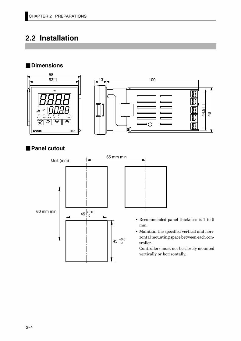
JDimensions
5853j 13 100
44.8
48
j
JPanel cutout
45 +0.60
45 +0.60
Unit (mm)65 mm min
60 mm min
• Recommended panel thickness is 1 to 5mm.
• Maintain the specified vertical and hori-zontalmounting spacebetween each con-troller.Controllers must not be closely mountedvertically or horizontally.

2.2 Installation
E5CK
2--5
JMountingAdapter
Panel
Watertightpacking
(1) Insert theE5CK controller into themounting hole in the panel at theposition shown in the figure above.
(2) Push the adapter along the controller body from the terminals up tothe panel, and fasten temporarily.
(3) Tighten the two fixing screws on the adapter. When tighteningscrews, tighten the two screws alternately keeping the torque toapproximately 0.29 to 0.39 N·m, or 3 to 4 kgf·cm.
E5CK-AA1-500 controller is provided with a terminal cover (E53-COV07). Fastenthe terminal cover as follows by using the snap pin.
About the TerminalCover

CHAPTER 2 PREPARATIONS
E5CK
2--6
2.3 Wiring Terminals
JTerminal arrangement
54321
10987613 14
11 12
OUT1
OUT2
SUB1
OPTION
IN
AC100-240V(AC/DC24V )
SOURCE
• Use ducts to separate input leads and power lines in order to protect thecontroller and its lines from external noise.
• We recommend using solderless terminals when wiring the controller.• Tighten the terminal screws using a torque no greater than 0.78 N·m,or 8 kgf·cmmax.Take carenot to tighten the terminal screws too tightly.
• Use the following type of solderless terminals for M3.5 screws.
7.2mm max.
7.2mm max.
In the following wiring diagrams, the left side of the terminal Nos. indi-cates the inside of the controller• Input power to terminal Nos. 4 and 5. Power specifications are as follows:
AC100-240V , 50/60Hz, 15VA(AC/DC24V , 50/60Hz, 6VA, 3.5W)
TheE5CKhas independentpower supplies for eachof the ter-minal blocks shown on the right. However, note that thepower supplies for blocks C (exclude relay output) and D areshared for the following option unit.•Option unit : E53---CKB or E53---CKF
About the powerblocks
A C54321
109876
C
D B
11 12
13 14
JPrecautionswhen wiring
JWiring
F Power supply5
4321
10
987613 14
11 12
2.3 Wiring Terminals
E5CK
2--7
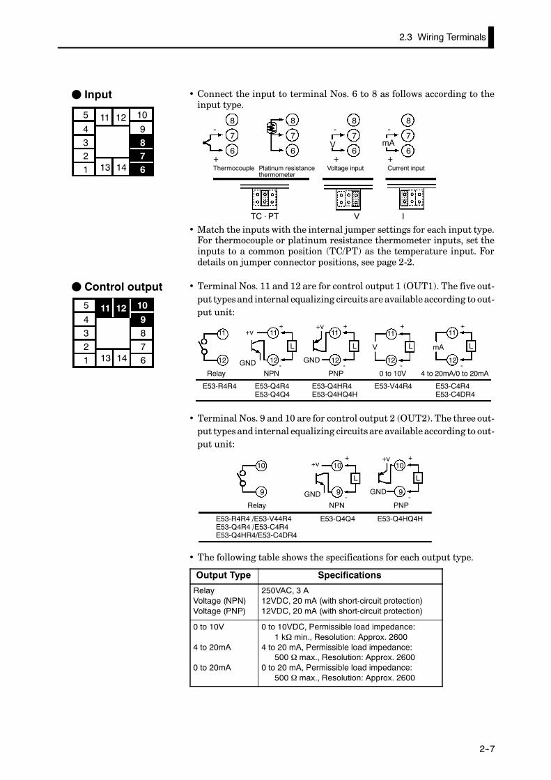
• Connect the input to terminal Nos. 6 to 8 as follows according to theinput type.
8
7
6
8
7
6
8
7
6
8
7
6
-
+
-
+
-
+
V mA
TC ⋅ PT V I
Thermocouple Platinum resistancethermometer
Voltage input Current input
• Match the inputs with the internal jumper settings for each input type.For thermocouple or platinum resistance thermometer inputs, set theinputs to a common position (TC/PT) as the temperature input. Fordetails on jumper connector positions, see page 2-2.
• Terminal Nos. 11 and 12 are for control output 1 (OUT1). The five out-put types and internal equalizing circuits are available according to out-put unit:
11
12
11
12
L
11
12
L
11
12
L
11
12
L
E53-R4R4 E53-Q4R4E53-Q4Q4
E53-Q4HR4E53-Q4HQ4H
E53-V44R4 E53-C4R4E53-C4DR4
NPN PNP 0 to 10V 4 to 20mA/0 to 20mA
+v+
-
+
-
+
-
+
-GND
mA
Relay
V
GND
+v
• Terminal Nos. 9 and 10 are for control output 2 (OUT2). The three out-put types and internal equalizing circuits are available according to out-put unit:
10
9
10
9
L
10
9
L
+v+
-
+
-GND
E53-Q4Q4 E53-Q4HQ4H
NPN PNP
E53-R4R4 /E53-V44R4E53-Q4R4 /E53-C4R4E53-Q4HR4/E53-C4DR4
Relay
GND
+v
• The following table shows the specifications for each output type.
Output Type Specifications
RelayVoltage (NPN)Voltage (PNP)
250VAC, 3 A12VDC, 20 mA (with short-circuit protection)12VDC, 20 mA (with short-circuit protection)
0 to 10V
4 to 20mA
0 to 20mA
0 to 10VDC, Permissible load impedance:1 kΩ min., Resolution: Approx. 2600
4 to 20 mA, Permissible load impedance:500 Ω max., Resolution: Approx. 2600
0 to 20 mA, Permissible load impedance:500 Ω max., Resolution: Approx. 2600
F Input
5
4321
10
987613 14
11 12
F Control output
5
4321
10
987613 14
11 12

CHAPTER 2 PREPARATIONS
E5CK
2--8
• Terminal Nos. 2 and 3 are for auxiliary output 1 (SUB1).
• The internal equalizing circuit for auxiliary output 1 is as follows:
3
2
• Relay specifications are as follows:SPST-NO, 250VAC, 1A
• Terminal Nos. 1, 13 and 14 are valid only when the option unit is set inthe controller.
• The following four connections are possible depending on the type ofoption unit.
13
14
1
13
14
1
13
14
1
13
14
1
SD
RD
SG
A
B
+
--4 to 20mA
E53-CK01
RS-232C
E53-CK03
RS-485
E53-CKB E53-CKF
Event input Transfer output
• For details on RS-232C and RS-485 communications functions, seeChapter 6 Using the Communications Function.
• Use event inputs under the following conditions
Contact input ON: 1 kΩ max., OFF: 100 kΩ min.
No-contact input ON: residual voltage 1.5V max., OFF: leakage current 0.1mAmax.
Polarities during no-contact input are as follows:
13
14
1
+
--
• Transfer output specifications are as follows:4 to 20 mA, Load 500 Ωmax., Resolution approx. 2600
F Auxiliary output 1
5
4321
10
987613 14
11 12
F Option
5
4321
10
987613 14
11 12

CHAPTER 3 BASIC OPERATION
3--1
CHAPTER 3BASIC OPERATION
This chapter describes an actual example for understanding the basicoperation of the E5CK.
CHAPTER3
3.1 Control Example 3---2. . . . . . . . . . . . . . . . . . . . . . .
3.2 Setting Input Specifications 3---3. . . . . . . . . . . . .
Input type 3---3. . . . . . . . . . . . . . . . . . . . . . . . . . . . .
Scaling 3---3. . . . . . . . . . . . . . . . . . . . . . . . . . . . . . . .
3.3 Setting Output Specifications 3---5. . . . . . . . . . .
Output assignments 3---5. . . . . . . . . . . . . . . . . . . .
Direct/reverse operation 3---5. . . . . . . . . . . . . . . .
Control period 3---6. . . . . . . . . . . . . . . . . . . . . . . . .
3.4 Setting Alarm Type 3---7. . . . . . . . . . . . . . . . . . . .
Alarm type 3---7. . . . . . . . . . . . . . . . . . . . . . . . . . . .
Alarm value 3---7. . . . . . . . . . . . . . . . . . . . . . . . . . .
Alarm hysteresis 3---8. . . . . . . . . . . . . . . . . . . . . . .
Close in alarm/open in alarm 3---8. . . . . . . . . . . .
3.5 Protect Mode 3---10. . . . . . . . . . . . . . . . . . . . . . . . . .
Security 3---10. . . . . . . . . . . . . . . . . . . . . . . . . . . . . . .
A/M key protect 3---10. . . . . . . . . . . . . . . . . . . . . . . .
3.6 Starting and Stopping Operation 3---11. . . . . . . .
3.7 Adjusting Control Operation 3---12. . . . . . . . . . . .
Changing the set point 3---12. . . . . . . . . . . . . . . . .
Manual operation 3---12. . . . . . . . . . . . . . . . . . . . . .
Auto-tuning (A.T.) 3---13. . . . . . . . . . . . . . . . . . . . .

CHAPTER 3 BASIC OPERATION
E5CK
3--2
3.1 Control Example
This chapter describes the following control example to facilitate under-standing of the basic operation of the E5CK controller.
This description assumes that the controller is operated under the follow-ing conditions.
• A humidity sensor of output 4 to 20 mA is connected to the controller.The measuring range of the humidity sensor is set to 10 to 95%.
• A humidifier is controlled by pulse output to maintain humidity at aconstant 60%.
• An alarm is output when the humidity exceeds the upper limit value(70%) or lower limit value (50%).
• Output unit: relay/relay type (E53-R4R4)
• Input type jumper connector: “I (current input)”
5
4
3
2
1
10
9
8
7
613 14
11 12
OUT1
OUT2
4 to 20mA
Humidifier
Control target
Humidity sensor
Alarm 1(deviation upper-and
lower-limit)
E5CK
SOURCE
AC100-240V(AC/DC24V )
F Setup

To switch the temperature unit from “_C” to “_F” for temperature unit, switch thesetting of the _C/_F selection” parameter to [ ] from [ ].
About the tempera-ture unit
3.2 Setting Input Specifications
E5CK
3--3
3.2 Setting Input Specifications
• Set the typeNo. (0 to 21) in the “input type” parameter. The factory set-ting is “2: K1 (thermocouple).”
• For details on input types and setting ranges, see page 5-22.
• When the voltage input and current input are selected, scalingmatchedto the control is required.
• The “scaling upper limit”, “scaling lower limit” and “decimal point”parameters (setup mode) are use for scaling.
• The “scaling upper limit” parameter sets the physical quantity to beexpressedby theupper limit value of input, and the“scaling lower limit”parameter sets the physical quantity to be expressed by the lower limitvalue of input. The “decimal point” parameter sets the number of digitspast the decimal point.
• The following figure shows scaling example of 4 to 20 mA input. Afterscaling, the humidity can be directly read. In this case, the “decimalpoint” parameter is set to “1”.
100%FS0
Readout (humidity)
Scaling upper limitvalue (95.0%)
Scaling lower limitvalue (10.0%)
Input (4 to 20 mA)
• When temperature input is selected, scaling is not required. This isbecause input is treated as the “temperature” as it is matched to theinput type. However, note that the upper and lower limit values of thesensor can be shifted. For example, if both theupper and lower limit val-ues are shifted by 1.2_C, the process value (before shift) is regarded as201.2_C after shift when input is 200_C before shift.
• To set input shift, set shift values in the “input shift upper limit” and“input shift lower limit” parameters (level 2 mode).
0100
Temperature
Upper limit value
Lower limit value
Input shift upper limit value
After shift
Before shift
Input shift lowerlimit value
Input (%FS)
J Input type
JScaling
F Input shift

CHAPTER 3 BASIC OPERATION
E5CK
3--4
In this example, let’s set the parameters as follows:“input type” = “17 (4 to 20 mA)”“scaling upper limit value” = “950”“scaling lower limit value” = “100”“decimal point” = “1”
(1) Select the menu display, and select [ ] (setup mode) using the
or keys. For details on selecting the menu display, see page
1-7.
(2) Press the key to enter the setup mode. The top parameter in the
setup mode [ ] “input type” is displayed. The parameter default
is “2”.
(3) Press the key until the display indicates “17”.
(4) Press the key to fix the set value. The display changes to [ ]
(“scaling upper limit value” parameter). The parameter default is“100”.
(5) Press the key until the display indicates “950”.
(6) Press the key to fix the set value. The display changes to [ ]
(“scaling lower limit value” parameter).The parameter default is “0”.
(7) Press the key until the display indicates “100”.
(8) Press the key to fix the set value. The display changes to [ ]
(“decimal point” parameter). The parameter default is “0”.
(9) Press the key until the display indicates “1”.
Setting Example
3.3 Setting Output Specifications
E5CK
3--5
3.3 Setting Output Specifications
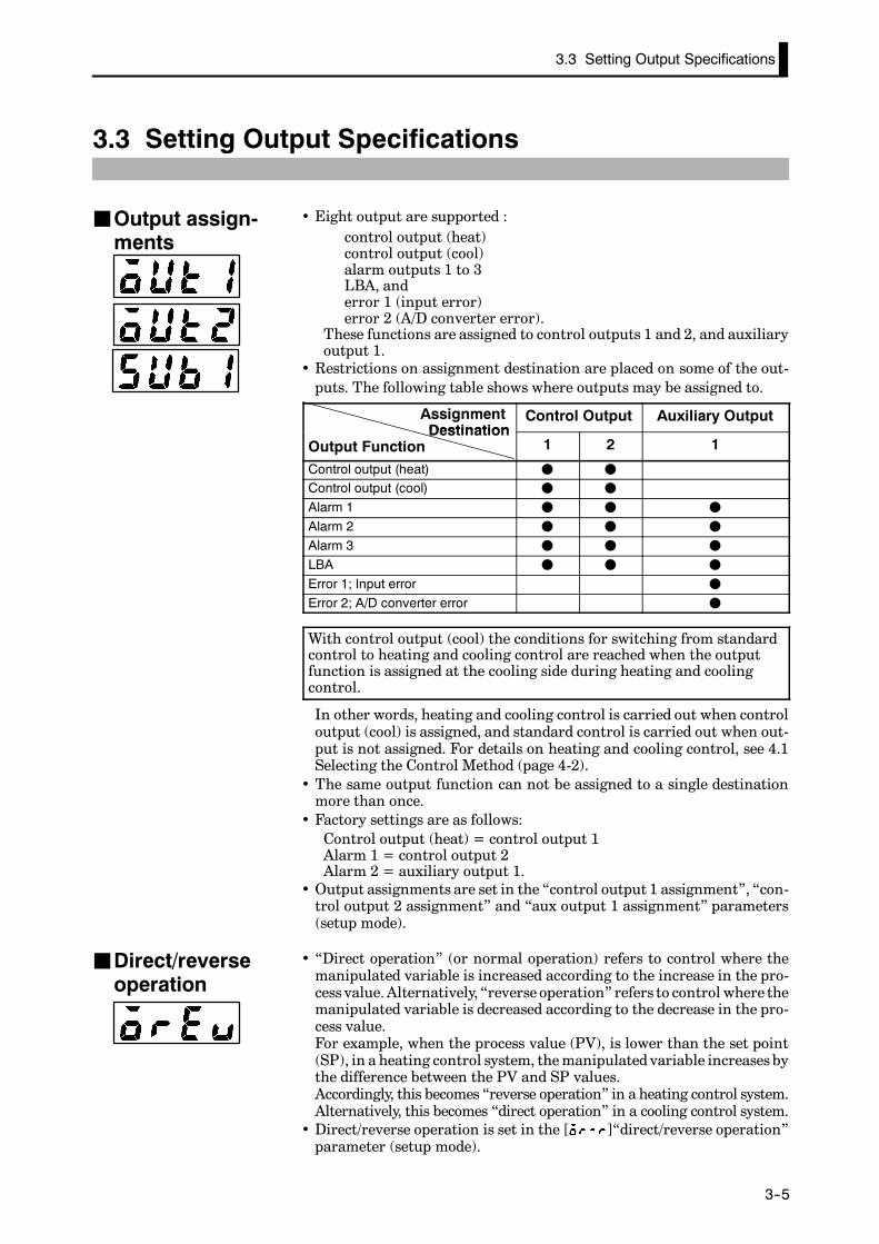
• Eight output are supported :control output (heat)control output (cool)alarm outputs 1 to 3LBA, anderror 1 (input error)error 2 (A/D converter error).
These functions are assigned to control outputs 1 and 2, and auxiliaryoutput 1.
• Restrictions on assignment destination are placed on some of the out-puts. The following table shows where outputs may be assigned to.
AssignmentDestination
Control Output Auxiliary OutputDestination
Output Function 1 2 1
Control output (heat) F F
Control output (cool) F F
Alarm 1 F F F
Alarm 2 F F F
Alarm 3 F F F
LBA F F F
Error 1; Input error F
Error 2; A/D converter error F
With control output (cool) the conditions for switching from standardcontrol to heating and cooling control are reached when the outputfunction is assigned at the cooling side during heating and coolingcontrol.
In other words, heating and cooling control is carried out when controloutput (cool) is assigned, and standard control is carried out when out-put is not assigned. For details on heating and cooling control, see 4.1Selecting the Control Method (page 4-2).
• The same output function can not be assigned to a single destinationmore than once.
• Factory settings are as follows:Control output (heat) = control output 1Alarm 1 = control output 2Alarm 2 = auxiliary output 1.
• Output assignments are set in the “control output 1 assignment”, “con-trol output 2 assignment” and “aux output 1 assignment” parameters(setup mode).
• “Direct operation” (or normal operation) refers to control where themanipulated variable is increased according to the increase in the pro-cess value.Alternatively, “reverse operation” refers to control where themanipulated variable is decreased according to the decrease in the pro-cess value.For example, when the process value (PV), is lower than the set point(SP), in a heating control system, themanipulated variable increases bythe difference between the PV and SP values.Accordingly, this becomes “reverse operation” in a heating control system.Alternatively, this becomes “direct operation” in a cooling control system.
• Direct/reverse operation is set in the [ ]“direct/reverse operation”parameter (setup mode).
JOutput assign-ments
JDirect/reverseoperation

CHAPTER 3 BASIC OPERATION
E5CK
3--6
• When the output unit is pulse output such as relay output, set the pulseoutput cycle (control period). Though a shorter pulse period providesbetter control performance, the control period should be set taking thelife expectancy of the output unit into consideration when the outputunit is relay.
• The control period is set in the “control period (heat)” parameter (level1 mode). Factory setting is “20:20 seconds.”
In this example, let’s set the parameters as follows:“control output 1 assignment” = “control output (heat)”“control output 2 assignment” = “alarm output 1”“direct/reverse operation” = “reverse operation”“control period” = “20 seconds”
All of the above settings in this example are factory settings. So, in thisexample, we are only going to check the parameter settings.
(1) Select the menu display, and select [ ] (setup mode) using the
or keys. For details on selecting the menu display, see page
1-7.
(2) Press the key to enter the setup mode. The top parameter in the
setup mode [ ] “input type” is displayed. In this example, the
parameter setting is “17: 4 to 20 mA.”
(3) Press the key until [ ] (“control output 1 assignment”
parameter) is displayed. The parameter default is [ ].
(4) As the setting in this example is to be left as it is, press the key.
The display changes to [ ] (“control output 2 assignment”parameter). The parameter default is [ ].
(5) As the setting in this example is to be left as it is, press the key
until [ ] (“direct/reverse operation” parameter) is displayed.The parameter default is [ ].
(6) As the setting in this example is to be left as it is, press the or
keys to select [ ] (level 1mode). For details on selecting themenudisplay, see page 1-7.
(7) Press the key to enter the level 1 mode. The top parameter in the
level 1 mode [ ] “AT execute/cancel” is displayed.
(8) Press the key until [ ] (“control period” parameter) is dis-
played. The parameter default is “20”. As the setting in this exampleis to be left as it is, quit key operation.
JControl period
Setting Example
1 second min.

3.4 Setting Alarm Type
E5CK
3--7
3.4 Setting Alarm Type
• Three alarm outputs are supported: alarms 1 to 3. Of these, only thealarm assigned as the output can be used.
• Alarm output conditions are determined according to the combinationof the “alarm type”, “alarm value” and “alarm hysteresis” parametersettings.
• The contact conditions when alarm output is ON can be set to “open”or “closed” in the “close in alarm/open in alarm” parameter.
• The following table shows the alarm types supported by the E5CK con-troller and their respective operations.
Alarm TypeAlarm Output Operation
Alarm TypeWhen X is positive When X is negative
1 Upper-and lower-limit alarm(deviation)
ONOFF
X X
SPAlways ON
2 Upper-limit alarm (deviation) ONOFF
X
SP
ONOFF
X
SP
3 Lower-limit alarm (deviation) ONOFF
X
SP
XONOFF
SP
4 Upper-and lower-limit rangealarm (deviation)
ONOFF
X X
SPAlways OFF
5Upper-and lower-limit alarmwith standby sequence(deviation)
ONOFF
X X
SPAlways OFF
6 Upper-limit alarm withstandby sequence (deviation)
ONOFF
X
SP
ONOFF
X
SP
7 Lower-limit alarm withstandby sequence (deviation)
ONOFF
X
SP
ONOFF
X
SP
8 Absolute-value upper-limitalarm
ONOFF
X
0
ONOFF
X
0
9 Absolute-value lower-limitalarm
ONOFF
X
0ONOFF
X
0
10 Absolute-value upper-limitalarm with standby sequence
ONOFF
X
0
ONOFF
X
0
11 Absolute-value lower-limitalarm with standby sequence
ONOFF
X
0
ONOFF
X
0
• Alarm types are set independently for each alarm in the “alarm 1 to 3”parameters (setupmode). Factory setting is “2:Upper-limit alarm(devi-ation)”.
• Alarm values are indicated by “X” in the table above. Alarm outputoperation differs according to whether the value of the alarm is positiveor negative.
• Alarm values are set independently for each alarm in the “alarm value1 to 3” parameters (level 1 mode). Factory setting is “0”.
JAlarm type
JAlarm value
CHAPTER 3 BASIC OPERATION
E5CK
3--8
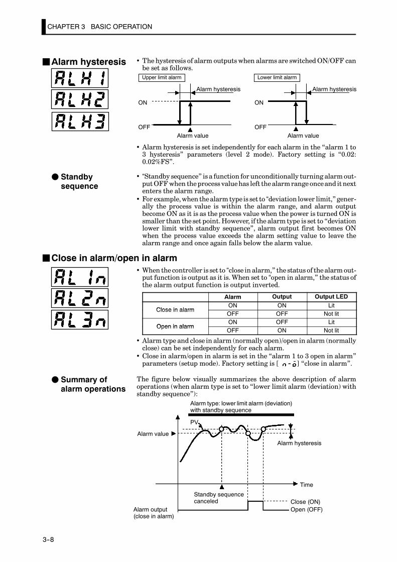
• The hysteresis of alarm outputswhen alarms are switchedON/OFF canbe set as follows.
ON
OFF
Alarm hysteresis
Alarm value Alarm value
ON
OFF
Upper limit alarm Lower limit alarm
Alarm hysteresis
• Alarm hysteresis is set independently for each alarm in the “alarm 1 to3 hysteresis” parameters (level 2 mode). Factory setting is “0.02:0.02%FS”.
• “Standby sequence” is a function for unconditionally turning alarmout-putOFFwhen theprocess valuehas left the alarmrange onceand itnextenters the alarm range.
• For example,when thealarm type is set to “deviation lower limit,”gener-ally the process value is within the alarm range, and alarm outputbecome ON as it is as the process value when the power is turned ON issmaller than the set point.However, if the alarm type is set to “deviationlower limit with standby sequence”, alarm output first becomes ONwhen the process value exceeds the alarm setting value to leave thealarm range and once again falls below the alarm value.
JClose in alarm/open in alarm• When the controller is set to “close in alarm,” the status of the alarmout-put function is output as it is. When set to “open in alarm,” the status ofthe alarm output function is output inverted.
Alarm Output Output LED
Close in alarmON ON Lit
Close in alarmOFF OFF Not lit
Open in alarmON OFF Lit
Open in alarmOFF ON Not lit
• Alarm type and close in alarm (normally open)/open in alarm (normallyclose) can be set independently for each alarm.
• Close in alarm/open in alarm is set in the “alarm 1 to 3 open in alarm”parameters (setup mode). Factory setting is [ ] “close in alarm”.
The figure below visually summarizes the above description of alarmoperations (when alarm type is set to “lower limit alarm (deviation) withstandby sequence”):
Alarm type: lower limit alarm (deviation)with standby sequence
Alarm value
Alarm output(close in alarm)
Standby sequencecanceled
PV
Alarm hysteresis
Time
Close (ON)Open (OFF)
JAlarm hysteresis
F Standbysequence
F Summary ofalarm operations

The decimal point of the alarm value conforms to the setting of the “decimal point”parameter (setup mode). In this example, the “decimal point” parameter is set to“1”. (During temperature input, the decimal point of the alarm value conforms tothe set sensor.)
About the DecimalPoint of the AlarmValue
3.4 Setting Alarm Type
E5CK
3--9
When a set point for a humidity exceeds10.0%, alarm1 will be output.In this example, let’s set the parameters as follows:“alarm type 1” = “1: (deviation upper-and lower-limit)”“alarm value 1” = “10.0”“alarm hysteresis” = “0.20”“close in alarm/open in alarm”= “ : close in alarm”
Meanings of parameters, “alarm histeresis” and “open in alarm/close inalarm” are the same settings at the shipment, so settings for operationsare omitted.
(1) Select themenudisplay, and select [ ] (setupmode) using the
or keys. For details on selecting the menu display, see page 1-7.
(2) Press the key to enter the setup mode. The top parameter in the
setup mode [ ] “input type” is displayed. In this example, the
parameter setting is “17: 4 to 20 mA”.
(3) Press the key until [ ] (“alarm type 1” parameter) is dis-
played. The parameter default is “2: deviation upper limit”.
(4) Press the key to return to “1: deviation upper and lower limit”.
(5) Select the menu key, and select [ ] (level 1 mode) using the
or keys. For details on selecting the menu display, see page 1-7.
(6) Press the key to enter the level 1 mode. The top parameter in the
level 1 mode [ ] “AT execute/cancel” is displayed.
(7) Press the key until [ ] (“alarm value 1” parameter) is dis-
played.
(8) In this example, the parameter setting is “0.0” so press the key
until “10.0” is displayed.
Setting Example
1 second min.

CHAPTER 3 BASIC OPERATION
E5CK
3--10
3.5 Protect Mode
• This parameter allowsyouto protectuntil startof operationparametersthat do not change during operation to prevent unwantedmodification.
• The set value of the “security” (protect) parameter specifies the rangeof protected parameters.
• When this parameter is set to “0”, parameters are not protected.• When this parameter is set to “1” to “3”, the number of modes that canbe displayed on the menu display is limited.When set to “1”, level 0 to 2, setup, expansion and optionmodes only canbeselected.Whenset to “2”, only level 0 to 2modes canbe selected.Whenset to “3”, only level 0 and 1 modes can be selected.
• When this parameter is set to “4” to “6”, operations in only the level 0mode can be selected, and themode is not displayed on themenudisplay.
• When this parameter is set to “5”, only the “PV/SP” parameter can beused.
• When this parameter is set to “6”, only the “PV/SP” parameter can beused. (The set point can not change.)
• Default is “1”.
• This parameter disables use of the A/M key during operation. For exam-
ple, if you protect use of the A/M key by the “A/M key protect” parameter(protectmode) during auto operation, the controller cannot be set to themanual mode, preventing manual operation of the controller duringoperation.
• Let’s protect the setup, expansion, option and calibrationmodes. Set theparameters as follows:
“security” = “2: Usable only in level 0 to 2 modes”
(1) Press for 1 second minium the A/M and keys simultaneously, the
controller enters the protect mode.(2) In theprotectmode, the top parameter in theprotectmode“security”
isdisplayed.Theparameterdefault is“1”.Press the key to change
the parameter setting to “2”.
(3) Press for 1 second minium the A/M and keys simultaneously, the
display changes to the “PV/SP monitor” parameter (level 0 mode).
JSecurity
JA/M key protect
Setting Example
A/M
A/M
3.6 Starting and Stopping Operation
E5CK
3--11
3.6 Starting and Stopping Operation
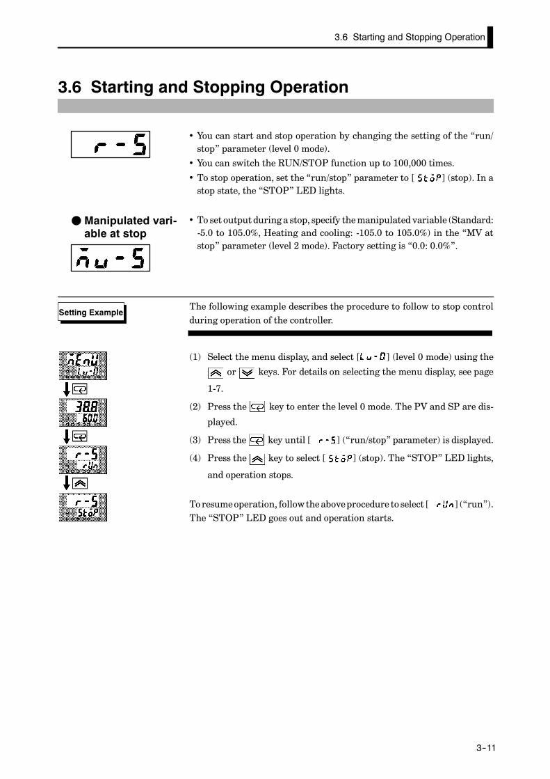
• You can start and stop operation by changing the setting of the “run/stop” parameter (level 0 mode).
• You can switch the RUN/STOP function up to 100,000 times.
• To stop operation, set the “run/stop” parameter to [ ] (stop). In astop state, the “STOP” LED lights.
• To set output during a stop, specify themanipulated variable (Standard:-5.0 to 105.0%, Heating and cooling: -105.0 to 105.0%) in the “MV atstop” parameter (level 2 mode). Factory setting is “0.0: 0.0%”.
The following example describes the procedure to follow to stop controlduring operation of the controller.
(1) Select the menu display, and select [ ] (level 0 mode) using the
or keys. For details on selecting the menu display, see page
1-7.
(2) Press the key to enter the level 0 mode. The PV and SP are dis-
played.
(3) Press the key until [ ] (“run/stop” parameter) is displayed.
(4) Press the key to select [ ] (stop). The “STOP” LED lights,
and operation stops.
To resumeoperation, followtheaboveprocedure to select [ ] (“run”).The “STOP” LED goes out and operation starts.
F Manipulated vari-able at stop
Setting Example

To prevent sudden changes in the manipulated variable when switching betweenmanual and auto operation, operation is resumed using the value that was activeimmediately before operation was switched, and the value is brought graduallycloser to the value immediately after operation was switched.
Balance-less,Bump-less Opera-tion
CHAPTER 3 BASIC OPERATION
E5CK
3--12
3.7 Adjusting Control Operation
• You can change the set point in the “set point” parameter (level 0mode).
• However, note that you cannot change the set point when the “security”parameter (protect mode) is set to “6”.
• To change the set point, press the or keys to select the desired
value. If you leave the setting for two seconds, the set point is updatedto the new setting.
In the following example, let’s change the humidity set point from “60%”to “50%”.
(1) Select the PV/SP monitor display.
(2) Press the key to change the setting to “50.0: 50.0%”.
• To set manual operation and manually set the manipulated variable,
press for 1 second minimum the A/M key. The controller enters the
manual mode.
• Themanipulated variable is displayedon theNo.2 display.To changethemanipulated variable, press the or keys. After two seconds, the
manipulated variable is updated to the new setting.
• Other modes cannot be selected while in the manual mode. To select
othermodes, press for 1 secondminimumthe A/M key.Themanualmode
is quit.
• The automatic return of display function does not work while in themanual mode.
• When switching between manual and auto operation, the manipulatedvariable is subject to balance-less, bump-less operation.
• If the power is interrupted during manual operation, manual operationis resumed at themanipulated variable at power interruption when thepower is reset.
• You can switch the AUTO/MANUAL function up to 100,000 times.
JChanging the setpoint
Setting Example
JManual operation
3.7 Adjusting Control Operation
E5CK
3--13
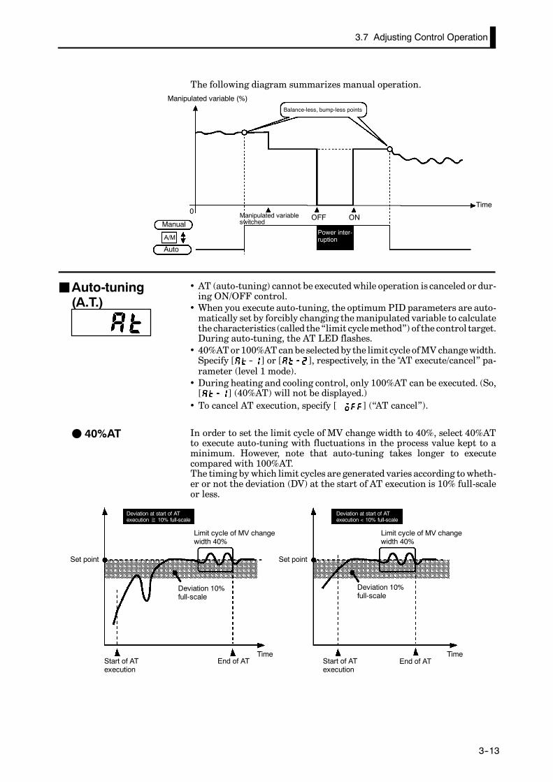
The following diagram summarizes manual operation.
OFF ON
A/M
0
Manipulated variable (%)Balance-less, bump-less points
Manual
Auto
TimeManipulated variableswitched
Power inter-ruption
• AT (auto-tuning) cannot be executedwhile operation is canceled or dur-ing ON/OFF control.
• When you execute auto-tuning, the optimum PID parameters are auto-matically set by forcibly changing themanipulated variable to calculatethe characteristics (called the“limit cyclemethod”) of the control target.During auto-tuning, the AT LED flashes.
• 40%ATor100%ATcanbeselectedby the limit cycle ofMV changewidth.Specify [ ] or [ ], respectively, in the “AT execute/cancel” pa-rameter (level 1 mode).
• During heating and cooling control, only 100%AT can be executed. (So,[ ] (40%AT) will not be displayed.)
• To cancel AT execution, specify [ ] (“AT cancel”).
In order to set the limit cycle of MV change width to 40%, select 40%ATto execute auto-tuning with fluctuations in the process value kept to aminimum. However, note that auto-tuning takes longer to executecompared with 100%AT.The timing by which limit cycles are generated varies according towheth-er or not the deviation (DV) at the start of AT execution is 10% full-scaleor less.
Deviation at start of ATexecution≧ 10% full-scale
Deviation at start of ATexecution < 10% full-scale
Limit cycle of MV changewidth 40%
Limit cycle of MV changewidth 40%
Set point Set point
Start of ATexecution
End of AT Start of ATexecution
End of ATTime Time
Deviation 10%full-scale
Deviation 10%full-scale
JAuto-tuning(A.T.)
F 40%AT

When control characteristics are already known, the PID parameters can be setdirectly to adjust control.PID parameters are set in the “proportional band” (P), “integrated time” (I) and“derivative time” (D) parameters (level 1 mode).For details on the setting ranges of these parameters, see chapter 5 Level 1 Mode(page 5-11).
About PIDParame-ters
CHAPTER 3 BASIC OPERATION
E5CK
3--14
In order to set the limit cycle ofMV changewidth to 100%, select 100%ATto shorten the AT execution time without worrying about fluctuations inthe process value.
Set point
Start of ATexecution
End of AT
Time
Limit cycle of MVchange width 100%
In this example, let’s execute 40%AT.
(1) Select [ ] (level 1mode) using the or keys. For details on
selecting the menu display, see page 1-7.
(2) Press the key to enter the level 1 mode. The top parameter in the
setup mode [ ] “AT execute/cancel” is displayed. In this example,
the parameter setting is [ ] “AT cancel”
(3) Press the key to specify [ ].
(4) TheATLED flashes, andAT execution starts.When theAT LEDgoesout (end of AT execution), the parameter automatically returns to[ ] (“AT cancel”).
• In addition to AT, the E5CK is also provided with fuzzy self-tuning (ST)that allows automatic calculation of the PID parameters suited to thecontrol target. However, note that the ST function operates only duringstandard control by temperature input. For further information regard-ing the ST, please see page 5-29 and A-10.
F 100%AT
Setting Example
AT execute
CHAPTER 4 APPLIED OPERATION
4--1
CHAPTER 4APPLIED OPERATION
This chapter describes each of the parameters required for making fulluse of the features of theE5CK.Read this chapter while referring to theparameter descriptions in chapter 5.
CHAPTER4
4.1 Selecting the Control Method 4---2. . . . . . . . . . . .
Heating and cooling control 4---2. . . . . . . . . . . . .
ON/OFF control 4---3. . . . . . . . . . . . . . . . . . . . . . .
4.2 Operating Condition Restrictions 4---4. . . . . . . .
Manipulated variable restrictions 4---4. . . . . . . .
Set point limiter 4---5. . . . . . . . . . . . . . . . . . . . . . .
SP ramp 4---5. . . . . . . . . . . . . . . . . . . . . . . . . . . . . .
4.3 How to Use Option Functions 4---7. . . . . . . . . . .
Event input 4---7. . . . . . . . . . . . . . . . . . . . . . . . . . .
Transfer output 4---8. . . . . . . . . . . . . . . . . . . . . . . .
4.4 LBA 4---9. . . . . . . . . . . . . . . . . . . . . . . . . . . . . . . . . .
4.5 Calibration 4---11. . . . . . . . . . . . . . . . . . . . . . . . . . . .
Calibrating thermocouple 4---12. . . . . . . . . . . . . . .
Calibrating platinumresistance thermometer 4---15. . . . . . . . . . . . . . . . .
Calibrating current input 4---17. . . . . . . . . . . . . . .
Calibrating voltage input 4---18. . . . . . . . . . . . . . .
Checking indication accuracy 4---20. . . . . . . . . . . .

CHAPTER 4 APPLIED OPERATION
E5CK
4--2
4.1 Selecting the Control Method
When selecting the control method, set the parameters according to thefollowing table. (Parameters are factory-set to heating control.)
Parameter
ControlMethod
Control output 1assignment
Control output 2assignment
Direct/Reverseoperations
Heating control(Standard) Control output (heat) -- Reverse operation
Cooling control(Standard) Control output (heat) -- Direct operation
Heating and coolingcontrol Control output (heat) Control output (cool) Reverse operation
For details on how to assign outputs, see 3.3 SettingOutputSpecifications(page 3---5).
• When heating and cooling control is selected, the “deadband” and“cool-ing coefficient” parameters can be used.
The dead band is set with the set point as its center. The dead band widthis the set value of the “deadband”parameter (level 1mode).Setting aposi-tive value produces a dead band, while setting a negative value producesan overlap band.
0 PV 0 PV
Output OutputDead band: deadband width = positive
Overlap band: deadband width = negative
Heatingside
Heatingside
Coolingside
Coolingside
Set point Set point
If the heating and cooling characteristics of the control target greatly dif-fer, preventing satisfactory control characteristics frombeing obtainedbythe samePID parameters, adjust the proportional band (P at cooling side)using the cooling coefficient to balance control between the heating andcooling sides. In heating and cooling control, P at the heating or coolingside is calculated by the following formula:
Heating side P = P; Cooling side P = cooling coefficient¢ P• In heating and cooling control, themanipulated variable output that isoutput when controller operation is stopped is dependent on the setvalue of the “MV at stop” parameter (level 2 mode) in the same way asfor standard control.
• However, note that inheating andcooling control, themanipulatedvari-ableat thecooling side is treatedas anegative value for thesake of conve-nience.When themanipulated variable at STOP is a negative value, themanipulated variable is output to only the cooling side, andwhen a posi-tive value, the manipulated variable is output to only the heating side.The factory setting is “0”. If the controller is operated using the factorysetting, the manipulated variable is not output to both the heating andcooling sides.
When the overlap band is set, the bumpless function that operates when switchingbetween manual and automatic operation may not work.
Switching withManual operation
JHeating andcooling controlF Dead band
F Cooling coeffi-cient
F Manipulated vari-able at stop

4.1 Selecting the Control Method
E5CK
4--3
• Switching between advanced PID control and ON/OFF control is car-ried out by the “PID /ON/OFF”parameter (expansionmode).When thisparameter is set to [ ], advanced PID control is selected, andwhenset to [ ], ON/OFF control is selected. Default is [ ].
• In ON/OFF control, hysteresis is provided in the programwhen switch-ing between ON and OFF to stabilize operation. The hysteresis widthprovided during ON/OFF control is simply referred to as “hysteresis.”Control output (heat) and control output (cool) functions are set in the“hysteresis (heat)” and “hysterisis (cool)” parameters, respectively.
• In standard control (heating or cooling control), hysteresis can be setonly for the heating side.
ON
OFF PV
Hysteresis (heat)
Set point
• Inheatingandcooling control, adeadband canbe set.So, 3-position con-trol is made possible.
ON
OFF PV
Hysteresis (heat)
Heatingside
Set point
Cooling side
Hysteresis (cool)
Dead band
Symbol Parameter Name: Mode Description
Control output 1assignment : Setup
For specifying control method
Control output 2assignment : Setup
For specifying control method
Direct/Reverseoperation : Setup For specifying control method
Dead band : Level 1 Heating and cooling control
Cooling coefficient : Level 1 Heating and cooling control
MV at stop : Level 2 Manipulated variable when controloperation is stopped
Hysteresis (heat) : Level 1 ON/OFF control
Hysteresis (cool) : Level 1 ON/OFF control
PID / ON/OFF : Expansion ON/OFF control
JON/OFF control
F Hysteresis
Parameters

CHAPTER 4 APPLIED OPERATION
E5CK
4--4
4.2 Operating Condition Restrictions
The upper-and lower-limit values of the manipulated variable can berestricted by theMV limiter, and the change rate of themanipulated vari-able can be restricted by the MV change rate limiter.
The upper-and lower-limit values of the manipulated variable are set inthe “MV upper limit” and “MV lower limit” parameters (level 2 mode).When the manipulated variable calculated by the E5CK is outside of therange of the MV limiter, actual outputs are dependent on the set value ofthese parameters.
100
0PV
Output (%)
MV upper limit value
MV lowerlimit value
In heating and cooling control, the manipulated variable at the coolingside is treated as a negative value for the sake of convenience. The upperlimit is set for the heating side (positive value), and the lower limit is setfor the cooling side (negative value) as shown in the following figure.
100
100
PV
Output (%)
MV upper limit value
MV lower limit value
Heatingside
Set point
Coolingside
The “MV change rate limit” parameter (level 2 mode) sets the maximumpermissible change width per second of the manipulated variable. If achange in the manipulated variable exceeds this parameter setting, thevalue calculated by the E5CK is reached while changing the value by theper-second value set in this parameter.
100
0
Output (%)
Switching pointTime
MV change ratelimit value
1 second
JManipulated vari-able restrictions
F MV limiter
F MV change ratelimiter

4.2 Operating Condition Restrictions
E5CK
4--5
The limiters are invalid or cannot be set when any of the following condi-tions occurs:
• During ON/OFF control• During ST execution• During AT execution (only by MV change rate limiter)• During manual operation• When operation is stopped• When an error has occurred.
The setting range of the set point is limited by the set point limiter. Theupper-and lower-limit values of this set point limiter are set in the “Setpoint upper limit” and “Set point lower limit” parameters (expansionmode), respectively. However, note that when the set point limiter is reset,the set point is forcibly changed to theupper-or lower-limit valueof thesetpoint limiter if the set point is out of the limiter range. Also, when the in-put type, temperature unit and scaling (sensor) range are changed, setpoint limiter is forcibly reset to the scaling (sensor) range.
Scaling (sensor) upper-and lower-limit values
Changed tothe new up-per limitvalue
Scaling (sensor) range
SP
Set point Upper-and lower-limit values of the limiter
Set point limiter
Setting range
Changed to upperlimit value
Input type changed
SP
A
B×
C B
With the SP ramp function, the controller operates according to the value(setpoint duringSP ramp) limitedbya changerate, insteadof thechangedset point when set point is changed. The interval in which the set pointduring SP ramp is limited is referred to as the “SP ramp”.
SP
Set pointSP ramp
SP ramp setvalue
SP ramp time unit
Time
Switching point
F Limiter operationconditions
JSet point limiter
JSP ramp

CHAPTER 4 APPLIED OPERATION
E5CK
4--6
Thechangerate during theSPramp isspecifiedby the “SPramp setvalue”and “SP ramp time unit” parameters. At the “SP ramp set value” default“0”, the SP ramp function is disabled.The set point changing in SP ramp can bemonitored in the “Set point dur-ing SP ramp” parameter (level 0 mode).
The limiters are invalid or cannot be set when any of the following condi-tions occurs:
If theSP ramp function isenabledwhen thepower is turnedON, andwhen“run” is switched to from “stop,” process valuemay reach the set point af-ter SP ramp in the sameway aswhen the set point is changed. In this case,operation is carried out with the process value regarded as the set pointbefore the change was made.The direction of the SP ramp changes according to the relationship be-tween the process value and the set point.
SP
PV
SP
PV
PV < SP PV > SP
Set pointSP ramp
SP ramp
Same changerate
Set point
Power ON
Time Time
Power ON
• Execution of auto-tuning starts after the end of SP ramp.
• When the controller is switched to the manual mode, the set pointchanges continuously until SP ramp ends.
• When an error occurs, the SP ramp function becomes invalid.
Symbol Parameter Name: Mode Description
MV upper limit : Level 2 Manipulated variable restrictions
MV lower limit : Level 2 Manipulated variable restrictions
MV change rate limit : Level 2 Manipulated variable restrictions
SP setting upper limit: Expansion SP setting restrictions
SP setting lower limit : Expansion SP setting restrictions
SP ramp set value : Level 2 SP changing restrictions
SP ramp time unit : Level 2 SP changing restrictions
F Operation at start
F Restrictions dur-ing SP ramp
Parameters
There is no order of prioritywhen inputting eventsand operatingthekeys.However,because event input of run/stop or auto/manual must be carried out in either of thephysical ON/OFF states, parameters ultimately conform to event input even if anattempt is made to switch the setting by key operation.
About the event in-put and key opera-tion
4.3 How to Use Option Functions
E5CK
4--7
4.3 How to Use Option Functions
• For details on the communications function, refer to Chapter 6 Usingthe Communications Function.
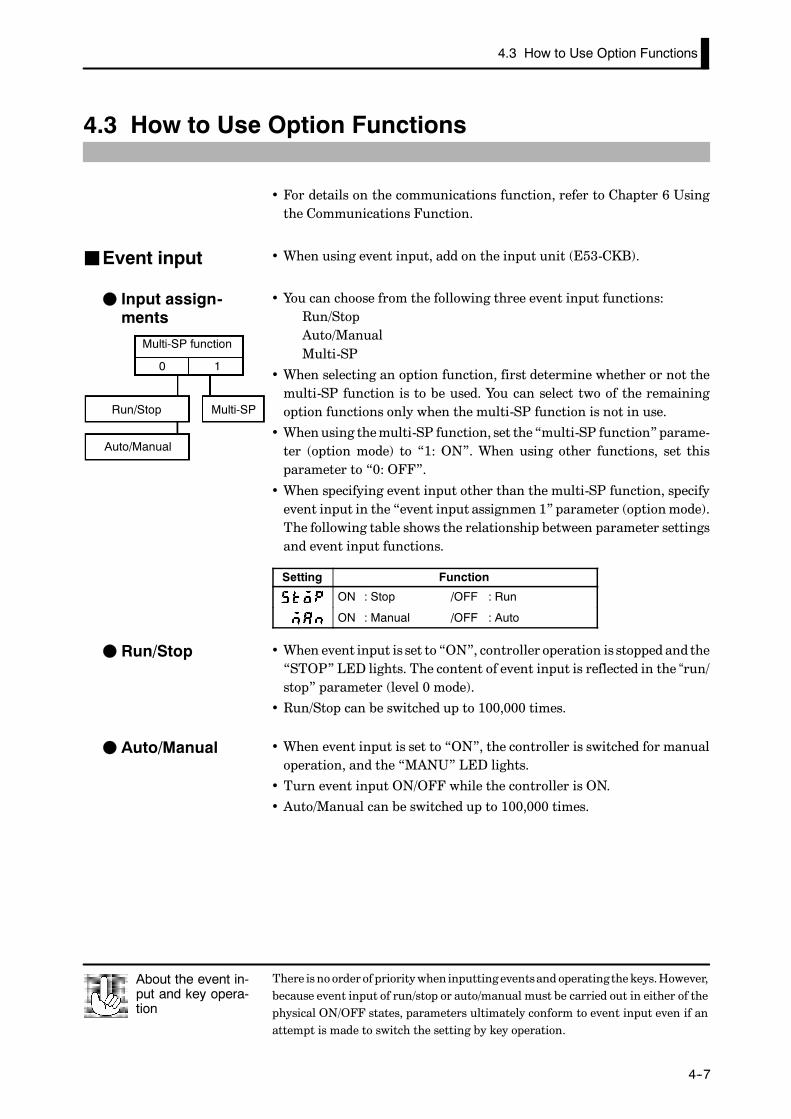
• When using event input, add on the input unit (E53-CKB).
• You can choose from the following three event input functions:Run/StopAuto/ManualMulti-SP
• When selecting an option function, first determine whether or not themulti-SP function is to be used. You can select two of the remainingoption functions only when the multi-SP function is not in use.
• Whenusing themulti-SP function, set the “multi-SP function”parame-ter (option mode) to “1: ON”. When using other functions, set thisparameter to “0: OFF”.
• When specifying event input other than the multi-SP function, specifyevent input in the “event input assignmen 1” parameter (optionmode).The following table shows the relationship between parameter settingsand event input functions.
Setting Function
ON : Stop /OFF : Run
ON : Manual /OFF : Auto
• When event input is set to “ON”, controller operation is stopped and the“STOP” LED lights. The content of event input is reflected in the “run/stop” parameter (level 0 mode).
• Run/Stop can be switched up to 100,000 times.
• When event input is set to “ON”, the controller is switched for manualoperation, and the “MANU” LED lights.
• Turn event input ON/OFF while the controller is ON.
• Auto/Manual can be switched up to 100,000 times.
JEvent input
F Input assign-ments
0 1
Multi-SP function
Run/Stop
Auto/Manual
Multi-SP
F Run/Stop
F Auto/Manual

CHAPTER 4 APPLIED OPERATION
E5CK
4--8
• The set points set to the “set point 0” and“set point 1” parameters (level1 mode) can be switched for use. However, note that these parameterscannot be set when the multi-SP function is not selected.
• The set point can be switched up to 100,000 times.• When event input is “OFF”, set point 0 is used, andwhen “ON” set point1 is used.
• When you have changed the set point, the set point of the currentlyselected parameter is changed.
• When you have switched between “set point 0” and “set point 1”, the SPramp function works if the SP ramp function is enabled. The followingexamples shows how the set point changes when you switch from setpoint 0 and set point 1.
OFF ON
SP
set point 1
set point 0
Event input
Time
SPramp
• When using transfer output, add on the communications unit (E53-CKF).• You can select the following data items in the “transfer output type”parameter (option mode) as the transfer outputs:
Set pointSet poing during SP rampProcess valueManipulated variable (heat), andManipulated variable (cool).
• These transfer outputs can be scaled according to the settings of the“transfer output upper limit” and “transfer output lower limit” param-eters before output. Setting of an upper limit value smaller than thelower limit value is allowed, so reverse scaling can also be carried out.Also, the scale can be enlargedby the upper-and lower-limit width speci-fied for each data item. The following example shows scaling of the read-ing side manipulated variable.
(mA)
20
4
20
4
0100
(mA)Transfer output Transfer output
Reverse scaling Enlarged scale
Transfer outputupper limit: 0
Transferoutput lowerlimit: 100
Manipu-latedvariable(%)
Transferoutput lowerlimit: 10
Transferoutput upperlimit: 80
Manipulatedvariable (%)
Symbol Parameter Name: Mode Application
Multi-SP function : Option Event input functions
Event input assignment 1 : Option Event input functions
Set point 0 : Level 1 Multi-SP
Set point 1 : Level 1 Multi-SP
Transfer output type : Option Transfer output designation
Transfer output upper limit : Option Transfer output scaling
Transfer output lower limit : Option Transfer output scaling
F Multi-SP
JTransfer output
Parameters

4.4 LBA
E5CK
4--9
4.4 LBA
• The LBA (Loop Break Alarm) function can be used only when assignedas an output. Also, the LBA function does not work when a memoryerror or A/D converter error occurs.
• LBA (Loop Break Alarm) is a function for judging that an error hasoccurred somewhere on the control loop and outputting an alarmwhenthe process value does not change with the manipulated variable at amaximumorminimumstate.Accordingly, theLBA function can beusedas a means for detecting a malfunctioning control loop.
• Normally, when output is set to maximum or minimum, the processvalue rises or falls after the dead time has elapsed. LBA is output if theprocess value does not change in the predicted direction after a fixedamount of timehas elapsed.This fixedamount of time is the “LBAdetec-tion time.”
• LBA operation sometimes becomes unstable when the process valuefluctuates considerably due to the control characteristics. The LBAdetection width is provided so that changes with respect to output canbe correctly detected. Changes smaller than the detection width due toLBA detection timing are not regarded as changes.
• The following example describes what happens when a heater burnoutat maximum output.
PV
LBA=ON
LBA detection time
LBA detection width
Output
Time
Heater burnout
LBA detection time
• LBA judgment is carried out at each LBA detection time from the pointofmaximumoutput. In above figure, the process value (PV) is changinggreatly at the 1st judgment timing, so LBA remains OFF.
• At the 2nd judgment timing, the process value increases as indicated bythe broken line of the process value is normal. This means that thechangewidth exceeds theLBAdetectionwidth, andLBAoutputremainsOFF.
• If theheaterburnsoutat thepoint shown in theabove figure, theprocessvalue “decreases.” Accordingly, it is judged that “the process value is notchanging in the increasing direction” at the 2nd judgment timing andthe LBA output becomes ON.
F LBA detectiontime
F LBA detectionwidth
F LBA detectionexample
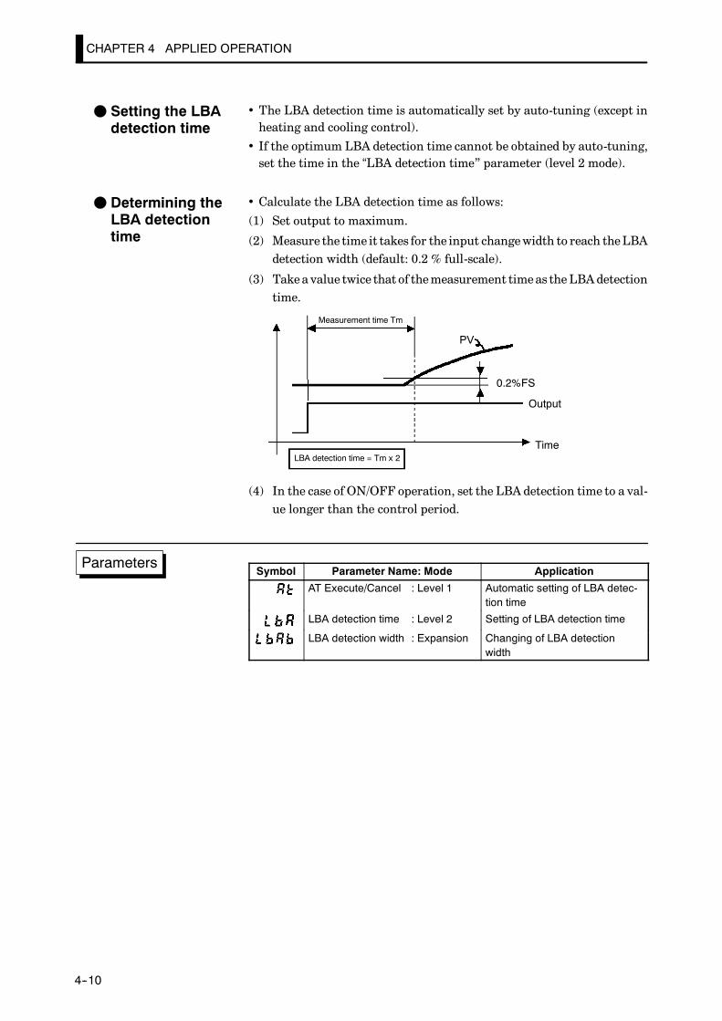
CHAPTER 4 APPLIED OPERATION
E5CK
4--10
• The LBA detection time is automatically set by auto-tuning (except inheating and cooling control).
• If the optimum LBA detection time cannot be obtained by auto-tuning,set the time in the “LBA detection time” parameter (level 2 mode).
• Calculate the LBA detection time as follows:
(1) Set output to maximum.
(2) Measure the time it takes for the input changewidth to reach theLBAdetection width (default: 0.2 % full-scale).
(3) Takea value twice that of themeasurement timeas the LBAdetectiontime.
PV
0.2%FS
Measurement time Tm
LBA detection time = Tm x 2
Output
Time
(4) In the case of ON/OFF operation, set the LBA detection time to a val-ue longer than the control period.
Symbol Parameter Name: Mode Application
AT Execute/Cancel : Level 1 Automatic setting of LBA detec-tion time
LBA detection time : Level 2 Setting of LBA detection time
LBA detection width : Expansion Changing of LBA detectionwidth
F Setting the LBAdetection time
F Determining theLBA detectiontime
Parameters

4.5 Calibration
E5CK
4--11
4.5 Calibration
• To calibrate the E5CK controller, select [ ] in the menu display toselect the calibration mode. [ ] is displayed.
• However, note that [ ] may not be displayed on the menu displaywhen, for example, the user is calibrating the E5CK controller for thefirst time. If this happens, [ ] is displayed by changing the “secu-rity” parameter (protect mode) to “0”.
• The parameters in the calibration mode are configured as follows.
0 to 10V0 to 5V 1 to 5V
Thermocouple
Thermocouple 1
Transfer output
Data save
Platinum resistancethermometer Voltage inputCurrent input
Thermocouple 2
Thermocouple 1 : K1/J1/L1/E/N/W/PLIIThermocouple 2 : K2/J2/L2/R/S/B/T/UPlatinum resistancethermometer : JPt100/Pt100
Only when transferoutput function issupported
• To select the desired parameter, press the key. Parameters are dis-played in the following order:Calibration of inputs→ Calibration of transfer output→Saving of calibration data
If the E5CK controller does not support the transfer output function,calibration of transfer output is automatically deleted from the calibra-tion procedure as follows:Calibration of inputs→ Saving of calibration data
• Only inputs that have been set in the “input type” parameter (setupmode) can be calibrated.To temporarily savedata for eachof thecalibra-tion parameters, press the key for 1 second.
• Transfer output can be calibrated only when the communications unit(E53-CKF) is set in the controller. To adjust data items, press the
or keys.
• The data save menu is displayed only when all calibration items havetemporarily been saved.
• After calibrating input, youmust always check indication accuracy. Fordetails, see page 4-20.
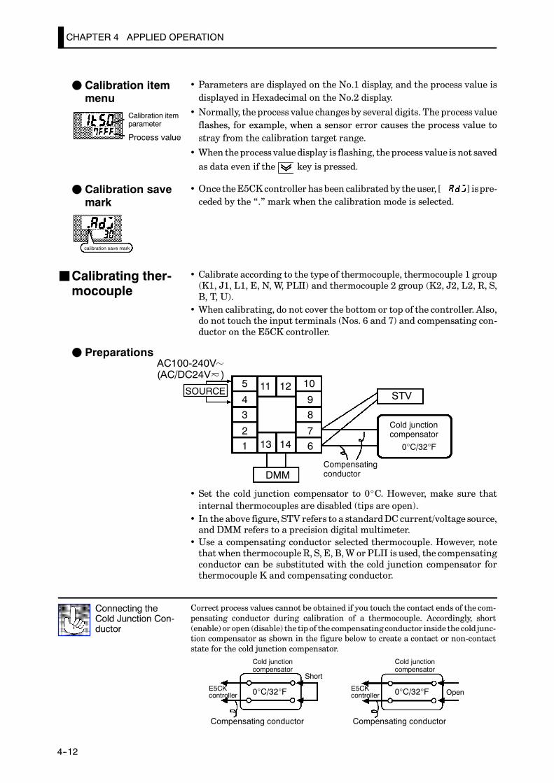
CHAPTER 4 APPLIED OPERATION
E5CK
4--12
• Parameters are displayed on the No.1 display, and the process value isdisplayed in Hexadecimal on the No.2 display.
• Normally, the process value changes by several digits. The process valueflashes, for example, when a sensor error causes the process value tostray from the calibration target range.
• When theprocess valuedisplay is flashing, theprocess value is not savedas data even if the key is pressed.
• Once theE5CKcontroller hasbeen calibratedby theuser, [ ] ispre-ceded by the “.” mark when the calibration mode is selected.
• Calibrate according to the type of thermocouple, thermocouple 1 group(K1, J1, L1, E, N, W, PLII) and thermocouple 2 group (K2, J2, L2, R, S,B, T, U).
• When calibrating, do not cover the bottom or top of the controller. Also,do not touch the input terminals (Nos. 6 and 7) and compensating con-ductor on the E5CK controller.
F Preparations
5
43
21
10
98
7613 14
11 12STV
DMM
0°C/32°F
Cold junctioncompensator
Compensatingconductor
SOURCE
AC100-240V(AC/DC24V )
• Set the cold junction compensator to 0_C. However, make sure thatinternal thermocouples are disabled (tips are open).
• In the above figure, STV refers to a standardDC current/voltage source,and DMM refers to a precision digital multimeter.
• Use a compensating conductor selected thermocouple. However, notethatwhen thermocouple R, S, E, B,W or PLII is used, the compensatingconductor can be substituted with the cold junction compensator forthermocouple K and compensating conductor.
Correct process values cannot be obtained if you touch the contact ends of the com-pensating conductor during calibration of a thermocouple. Accordingly, short(enable) or open (disable) the tip of the compensating conductor inside the cold junc-tion compensator as shown in the figure below to create a contact or non-contactstate for the cold junction compensator.
Connecting theCold Junction Con-ductor
0°C/32°F 0°C/32°F
Cold junctioncompensator
Cold junctioncompensator
E5CKcontroller
E5CKcontroller
Compensating conductor Compensating conductor
Short
Open
F Calibration itemmenu
Calibration itemparameter
Process value
F Calibration savemark
calibration save mark
JCalibrating ther-mocouple
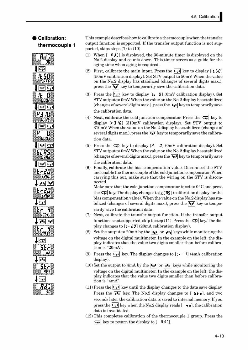
4.5 Calibration
E5CK
4--13
This exampledescribeshowto calibratea thermocouplewhen thetransferoutput function is supported. If the transfer output function is not sup-ported, skips steps (7) to (10).
(1) When [ ] is displayed, the 30-minute timer is displayed on theNo.2 display and counts down. This timer serves as a guide for theaging time when aging is required.
(2) First, calibrate the main input. Press the key to display [ ](50mV calibration display). Set STV output to 50mV.When the valueon the No.2 display has stabilized (changes of several digits max.),press the key to temporarily save the calibration data.
(3) Press the key to display [ ] (0mV calibration display). SetSTV output to 0mV.When thevalue on theNo.2 display has stabilized(changes of several digitsmax.), press the key to temporarily savethe calibration data.
(4) Next, calibrate the cold junction compensator. Press the key todisplay [ ] (310mV calibration display). Set STV output to310mV.When the value on the No.2 display has stabilized (changes ofseveral digitsmax.), press the key to temporarily save thecalibra-tion data.
(5) Press the key to display [ ] (0mV calibration display). SetSTV output to 0mV.When thevalue on theNo.2 display has stabilized(changes of several digitsmax.), press the key to temporarily savethe calibration data.
(6) Finally, calibrate the bias compensation value. Disconnect the STV,and enable the thermocouple of the cold junction compensator.Whencarrying this out, make sure that the wiring on the STV is discon-nected.Make sure that the cold junction compensator is set to 0_C and pressthe key.Thedisplay changes to [ ] (calibrationdisplay for thebias compensation value).When thevalue on theNo.2display hassta-bilized (changes of several digits max.), press the key to tempo-rarily save the calibration data.
(7) Next, calibrate the transfer output function. If the transfer outputfunction isnot supported, skip to step (11).Press the key.Thedis-play changes to [ ] (20mA calibration display).
(8) Set the output to 20mA by the or keys while monitoring thevoltage on the digital multimeter. In the example on the left, the dis-play indicates that the value two digits smaller than before calibra-tion is “20mA”.
(9) Press the key. The display changes to [ ] (4mA calibrationdisplay).
(10)Set the output to 4mA by the or keys while monitoring thevoltage on the digital multimeter. In the example on the left, the dis-play indicates that the value two digits smaller than before calibra-tion is “4mA”.
(11)Press the key until the display changes to the data save display.Press the key. The No.2 display changes to [ ], and twoseconds later the calibration data is saved to internal memory. If youpress the key when the No.2 display reads [ ], the calibrationdata is invalidated.
(12)This completes calibration of the thermocouple 1 group. Press thekey to return the display to [ ].
F Calibration:thermocouple 1

CHAPTER 4 APPLIED OPERATION
E5CK
4--14
This exampledescribeshowto calibratea thermocouplewhen thetransferoutput function is supported. If the transfer output function is not sup-ported, skips steps (7) to (10).
(1) When [ ] is displayed, the 30-minute timer is displayed on theNo.2 display and counts down. This timer serves as a guide for theaging time when aging is required.
(2) First, calibrate the main input. Press the key to display [ ](20mV calibration display). Set STV output to 20mV.When the valueon the No.2 display has stabilized (changes of several digits max.),press the key to temporarily save the calibration data.
(3) Press the key to display [ ] (0mV calibration display). SetSTV output to 0mV.When thevalue on theNo.2 display has stabilized(changes of several digitsmax.), press the key to temporarily savethe calibration data.
(4) Next, calibrate the cold junction compensator. Press the key todisplay [ ] (310mV calibration display). Set STV output to310mV.When the value on the No.2 display has stabilized (changes ofseveral digitsmax.), press the key to temporarily save thecalibra-tion data.
(5) Press the key to display [ ] (0mV calibration display). SetSTV output to 0mV.When thevalue on theNo.2 display has stabilized(changes of several digitsmax.), press the key to temporarily savethe calibration data.
(6) Finally, calibrate the bias compensation value. Disconnect the STV,and enable the thermocouple of the cold junction compensator.Whencarrying this out, make sure that the wiring on the STV is discon-nected.Make sure that the cold junction compensator is set to 0_C and pressthe key. The display changes to [ ] (calibration display forthe bias compensation value).When the value on theNo.2 display hasstabilized (changes of several digitsmax.), press the key to tempo-rarily save the calibration data.
(7) Next, calibrate the transfer output function. If the transfer outputfunction isnot supported, skip to step (11).Press the key.Thedis-play changes to [ ] (20mA calibration display).
(8) Set the output to 20mA by the or keys while monitoring thevoltage on the digital multimeter. In the example on the left, the dis-play indicates that the value two digits smaller than before calibra-tion is “20mA”.
(9) Press the key. The display changes to [ ] (4mA calibrationdisplay).
(10)Set the output to 4mA by the or keys while monitoring thevoltage on the digital multimeter. In the example on the left, the dis-play indicates that the value two digits smaller than before calibra-tion is “4mA”.
(11)Press the key until the display changes to the data save display.Press the key. The No.2 display changes to [ ], and twoseconds later the calibration data is saved to internal memory. If youpress the key when the No.2 display reads [ ], the calibrationdata is invalidated.
(12)This completes calibration of the thermocouple 2 group. Press thekey to return the display to [ ].
F Calibration:thermocouple 2
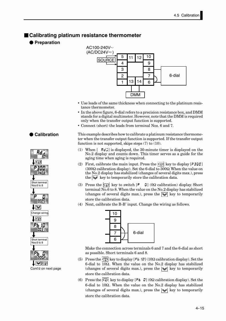
4.5 Calibration
E5CK
4--15
JCalibrating platinum resistance thermometerF Preparation
5
43
21
10
98
7613 14
11 12
6-dial
DMM
SOURCE
AC100-240V(AC/DC24V )
• Use leads of the same thickness when connecting to the platinum resis-tance thermometer.
• In the above figure, 6-dial refers to a precision resistancebox, andDMMstands for a digital multimeter.However, note that theDMM is requiredonly when the transfer output function is supported.
• Connect (short) the leads from terminal Nos. 6 and 7.
This example describeshow to calibrate a platinum resistance thermome-ter when the transfer output function is supported. If the transfer outputfunction is not supported, skips steps (7) to (10).
(1) When [ ] is displayed, the 30-minute timer is displayed on theNo.2 display and counts down. This timer serves as a guide for theaging time when aging is required.
(2) First, calibrate the main input. Press the key to display [ ](300Ω calibration display). Set the 6-dial to 300Ω. When the value onthe No.2 display has stabilized (changes of several digits max.), pressthe key to temporarily store the calibration data.
(3) Press the key to switch [ ] (0Ω calibration) display. Shortterminal No.6 to 8. When the value on the No.2 display has stabilized(changes of several digits max.), press the key to temporarilystore the calibration data.
(4) Next, calibrate the B-B’ input. Change the wiring as follows.
10
98
76
6-dial
Make the connection across terminals 6 and 7 and the 6-dial as shortas possible. Short terminals 6 and 8.
(5) Press the key to display [ ] (10Ω calibration display). Set the6-dial to 10Ω.. When the value on the No.2 display has stabilized(changes of several digits max.), press the key to temporarilystore the calibration data.
(6) Press the key to display [ ] (0Ω calibration display). Set the6-dial to 10Ω.. When the value on the No.2 display has stabilized(changes of several digits max.), press the key to temporarily
store the calibration data.
F Calibration
Cont’d on next page
Change wiring.
Short terminalNos.6 to 8
Short terminalNos.6 to 8
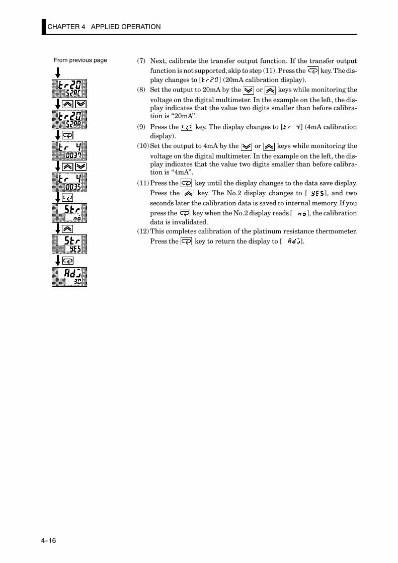
CHAPTER 4 APPLIED OPERATION
E5CK
4--16
(7) Next, calibrate the transfer output function. If the transfer outputfunction isnot supported, skip to step (11).Press the key.Thedis-play changes to [ ] (20mA calibration display).
(8) Set the output to 20mA by the or keys while monitoring the
voltage on the digital multimeter. In the example on the left, the dis-play indicates that the value two digits smaller than before calibra-tion is “20mA”.
(9) Press the key. The display changes to [ ] (4mA calibrationdisplay).
(10)Set the output to 4mA by the or keys while monitoring the
voltage on the digital multimeter. In the example on the left, the dis-play indicates that the value two digits smaller than before calibra-tion is “4mA”.
(11)Press the key until the display changes to the data save display.Press the key. The No.2 display changes to [ ], and twoseconds later the calibration data is saved to internal memory. If youpress the key when the No.2 display reads [ ], the calibrationdata is invalidated.
(12)This completes calibration of the platinum resistance thermometer.Press the key to return the display to [ ].
From previous page
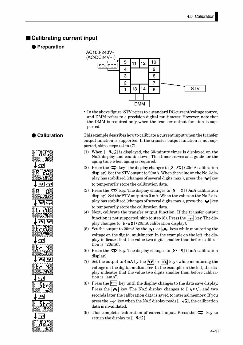
4.5 Calibration
E5CK
4--17
JCalibrating current input
F Preparation
5
43
21
10
98
7613 14
11 12
STV
DMM
SOURCE
AC100-240V(AC/DC24V )
• In the above figure, STV refers to a standardDC current/voltage source,and DMM refers to a precision digital multimeter. However, note thatthe DMM is required only when the transfer output function is sup-ported.
This exampledescribeshow to calibrate a current inputwhen the transferoutput function is supported. If the transfer output function is not sup-ported, skips steps (4) to (7).(1) When [ ] is displayed, the 30-minute timer is displayed on the
No.2 display and counts down. This timer serves as a guide for theaging time when aging is required.
(2) Press the key. The display changes to [ ] (20mA calibrationdisplay). Set theSTVoutput to 20mA.When thevalue on theNo.2dis-play has stabilized (changes of several digits max.), press the keyto temporarily store the calibration data.
(3) Press the key. The display changes to [ ] (0mA calibrationdisplay). Set the STV output to 0mA.When the value on theNo.2 dis-play has stabilized (changes of several digits max.), press the keyto temporarily store the calibration data.
(4) Next, calibrate the transfer output function. If the transfer outputfunction is not supported, skip to step (8). Press the key. The dis-play changes to [ ] (20mA calibration display).
(5) Set the output to 20mA by the or keys while monitoring thevoltage on the digital multimeter. In the example on the left, the dis-play indicates that the value two digits smaller than before calibra-tion is “20mA”.
(6) Press the key. The display changes to [ ] (4mA calibrationdisplay).
(7) Set the output to 4mA by the or keys while monitoring thevoltage on the digital multimeter. In the example on the left, the dis-play indicates that the value two digits smaller than before calibra-tion is “4mA”.
(8) Press the key until the display changes to the data save display.Press the key. The No.2 display changes to [ ], and twoseconds later the calibration data is saved to internal memory. If youpress the key when the No.2 display reads [ ], the calibrationdata is invalidated.
(9) This completes calibration of current input. Press the key toreturn the display to [ ].
F Calibration

CHAPTER 4 APPLIED OPERATION
E5CK
4--18
JCalibrating voltage inputF Preparation
5
43
21
10
98
7613 14
11 12
STV
DMM
SOURCE
AC100-240V(AC/DC24V )
• In the above figure, STV refers to a standardDC current/voltage source,and DMM refers to a precision digital multimeter. However, note thatthe DMM is required only when the transfer output function is sup-ported.
This example describes how to calibrate voltage input when the transferoutput function is supported. If the transfer output function is not sup-ported, skips steps (4) to (7).(1) When [ ] is displayed, the 30-minute timer is displayed on the
No.2 display and counts down. This timer serves as a guide for theaging time when aging is required.
(2) Press the key. The display changes to [ ] (5 V calibration dis-play). Set the STV output to 5V. When the value on the No.2 displayhas stabilized (changes of several digits max.), press the key to
temporarily store the calibration data.
(3) Press the key. The display changes to [ ] (0V calibration dis-play). Set the STV output to 0V. When the value on the No.2 displayhas stabilized (changes of several digits max.), press the key to
temporarily store the calibration data.(4) Next, calibrate the transfer output function. If the transfer output
function is not supported, skip to step (8). Press the key. The dis-play changes to [ ] (20mA calibration display).
(5) Set the output to 20mA by the or keys while monitoring thevoltage on the digital multimeter. In the example on the left, the dis-play indicates that the value two digits smaller than before calibra-tion is “20mA”.
(6) Press the key. The display changes to [ ] (4mA calibrationdisplay).
(7) Set the output to 4mA by the or keys while monitoring thevoltage on the digital multimeter. In the example on the left, the dis-play indicates that the value two digits smaller than before calibra-tion is “4mA”.
(8) Press the key until the display changes to the data save display.Press the key. The No.2 display changes to [ ], and twoseconds later the calibration data is saved to internal memory. If youpress the key when the No.2 display reads [ ], the calibrationdata is invalidated.
(9) This completes calibration of voltage input (0 to 5V, 1 to 5V).Press thekey to return the display to [ ].
F Calibration:0 to 5 V, 1 to 5 V
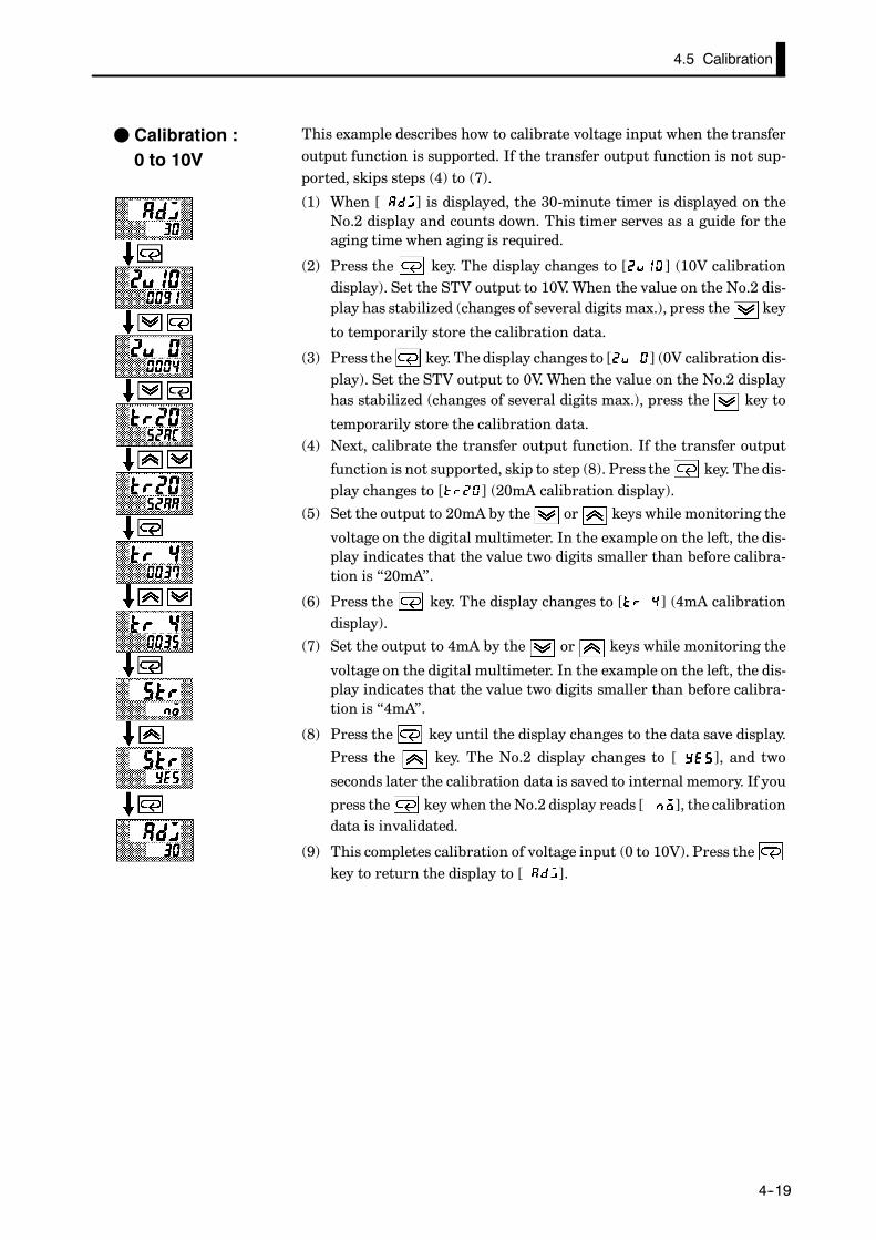
4.5 Calibration
E5CK
4--19
This example describes how to calibrate voltage input when the transferoutput function is supported. If the transfer output function is not sup-ported, skips steps (4) to (7).
(1) When [ ] is displayed, the 30-minute timer is displayed on theNo.2 display and counts down. This timer serves as a guide for theaging time when aging is required.
(2) Press the key. The display changes to [ ] (10V calibrationdisplay). Set the STV output to 10V. When the value on the No.2 dis-play has stabilized (changes of several digits max.), press the key
to temporarily store the calibration data.
(3) Press the key. The display changes to [ ] (0V calibration dis-play). Set the STV output to 0V. When the value on the No.2 displayhas stabilized (changes of several digits max.), press the key to
temporarily store the calibration data.(4) Next, calibrate the transfer output function. If the transfer output
function is not supported, skip to step (8). Press the key. The dis-play changes to [ ] (20mA calibration display).
(5) Set the output to 20mA by the or keys while monitoring the
voltage on the digital multimeter. In the example on the left, the dis-play indicates that the value two digits smaller than before calibra-tion is “20mA”.
(6) Press the key. The display changes to [ ] (4mA calibrationdisplay).
(7) Set the output to 4mA by the or keys while monitoring the
voltage on the digital multimeter. In the example on the left, the dis-play indicates that the value two digits smaller than before calibra-tion is “4mA”.
(8) Press the key until the display changes to the data save display.
Press the key. The No.2 display changes to [ ], and two
seconds later the calibration data is saved to internal memory. If you
press the key when the No.2 display reads [ ], the calibrationdata is invalidated.
(9) This completes calibration of voltage input (0 to 10V). Press thekey to return the display to [ ].
F Calibration :0 to 10V
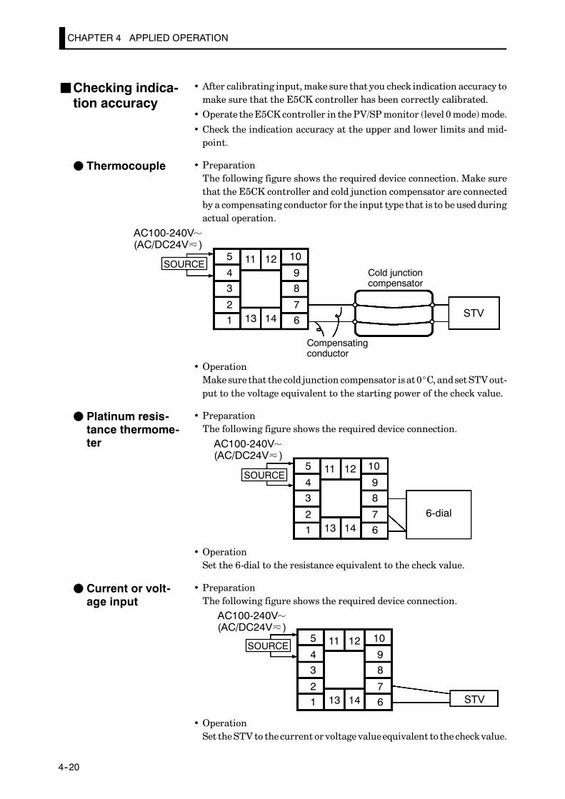
CHAPTER 4 APPLIED OPERATION
E5CK
4--20
• After calibrating input,make sure that you check indication accuracy tomake sure that the E5CK controller has been correctly calibrated.
• Operate theE5CKcontroller in the PV/SPmonitor (level 0mode)mode.
• Check the indication accuracy at the upper and lower limits and mid-point.
• PreparationThe following figure shows the required device connection. Make surethat the E5CK controller and cold junction compensator are connectedby a compensating conductor for the input type that is to be usedduringactual operation.
5
43
21
10
98
7613 14
11 12
STV
Cold junctioncompensator
Compensatingconductor
SOURCE
AC100-240V(AC/DC24V )
• OperationMake sure that the cold junction compensator is at0_C, andset STVout-put to the voltage equivalent to the starting power of the check value.
• PreparationThe following figure shows the required device connection.
5
43
21
10
98
7613 14
11 12
6-dial
SOURCE
AC100-240V(AC/DC24V )
• OperationSet the 6-dial to the resistance equivalent to the check value.
• PreparationThe following figure shows the required device connection.
5
43
21
10
98
7613 14
11 12
STV
SOURCE
AC100-240V(AC/DC24V )
• OperationSet theSTV to thecurrent or voltage valueequivalent to the checkvalue.
JChecking indica-tion accuracy
F Thermocouple
F Platinum resis-tance thermome-ter
F Current or volt-age input

CHAPTER 5 PARAMETERS
5--1
CHAPTER 5PARAMETERS
This chapter describes the parameters of theE5CK. Use this chapter asa reference guide.
CHAPTER5
Conventions Used in this Chapter 5-2. . . . . . . . . . . .
Protect Mode 5-3. . . . . . . . . . . . . . . . . . . . . . . . . . . . . . .
Manual Mode 5-5. . . . . . . . . . . . . . . . . . . . . . . . . . . . . .
Level 0 Mode 5-6. . . . . . . . . . . . . . . . . . . . . . . . . . . . . . .
Level 1 Mode 5-9. . . . . . . . . . . . . . . . . . . . . . . . . . . . . . .
Level 2 Mode 5-15. . . . . . . . . . . . . . . . . . . . . . . . . . . . . . .
Setup Mode 5-21. . . . . . . . . . . . . . . . . . . . . . . . . . . . . . . .
Expansion Mode 5-27. . . . . . . . . . . . . . . . . . . . . . . . . . . .
Option Mode 5-32. . . . . . . . . . . . . . . . . . . . . . . . . . . . . . .
Calibration Mode 5-36. . . . . . . . . . . . . . . . . . . . . . . . . . .
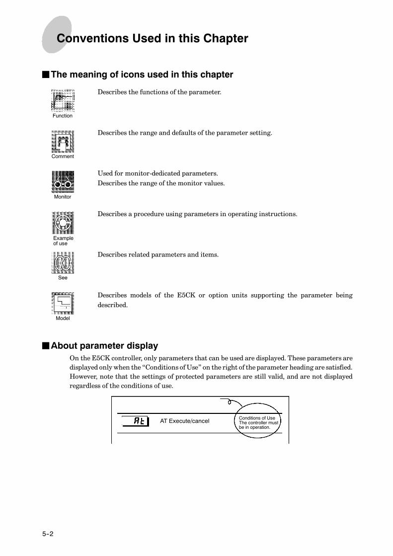
CHAPTER 5 PARAMETERS
E5CK
5--2
JThe meaning of icons used in this chapter
Describes the functions of the parameter.
Describes the range and defaults of the parameter setting.
Used for monitor-dedicated parameters.Describes the range of the monitor values.
Describes a procedure using parameters in operating instructions.
Describes related parameters and items.
Describes models of the E5CK or option units supporting the parameter beingdescribed.
JAbout parameter displayOn the E5CK controller, only parameters that can be used are displayed. These parameters aredisplayed only when the “Conditions ofUse” on the right of the parameter heading are satisfied.However, note that the settings of protected parameters are still valid, and are not displayedregardless of the conditions of use.
Conditions of UseThe controller mustbe in operation.
AT Execute/cancel
Conventions Used in this Chapter
Function
Comment
Monitor
Exampleof use
See
Model

E5CK
5--3
• The protect mode is for disabling (protecting) the functions of the menu key or A/M
key. Before changing parameters in this mode, first make sure that protecting the
menu key or A/M key will not cause any problems in operation.
• To select thismode, press the A/M key and key simultaneously for 1 secondmini-
mum. To exit this mode, press the A/M key and key down again simultaneously
for 1 second minimum.• The following table shows theparameters supported in thismodeand thepagewherethe parameter is described.
Symbol Parameter Name PageSecurity 5-3[A/M] key protect 5-4
Security
• This parameter specifies which parameters are protected. However, note that theprotect mode and manual mode cannot be protected.
• When this parameter is set to “0” to “3”, only the modes indicated by the “f” markin the table below can be selectedon themenudisplay.For example,when thisparam-eter is set to “2”, only level 0 to 2 modes can be selected.
ModeSet value
Mode0 1 2 3 4 5 6
Calibration f
Option f f
Expansion f f
Setup f f
Level 2 f f f
Level 1 f f f f
Level 0 f f f f f f ∗
• When this parameter is set to “4” to “6”, operations in only the level 0 mode can beselected, and the mode is not displayed on the menu display.
• When this parameter is set to “5”, only the “PV/SP” parameter in the level 0 modecan be used.
• When this parameter is set to “6”, only the “PV/SP” parameter in the level 0 modecan be used. (The set point cannot change.)
• Default is “1”. (Only the calibration mode is protected.)
F Related article3.5 Protect Mode (page 3-10)
Protect Mode
Function
Comment
See

CHAPTER 5 PARAMETERS
E5CK
5--4
[A/M] key protect
• Invalidate the function of the key. In otherwords,you cannotswitchbetween the
auto and manual operations by key operation.
• [ ] : A/M key protect ON
• [ ] : A/M key protect canceled
• Default = [ ]
F Related article3.5 Protect Mode (page 3-10)
Protect Mode
Function
Comment
See
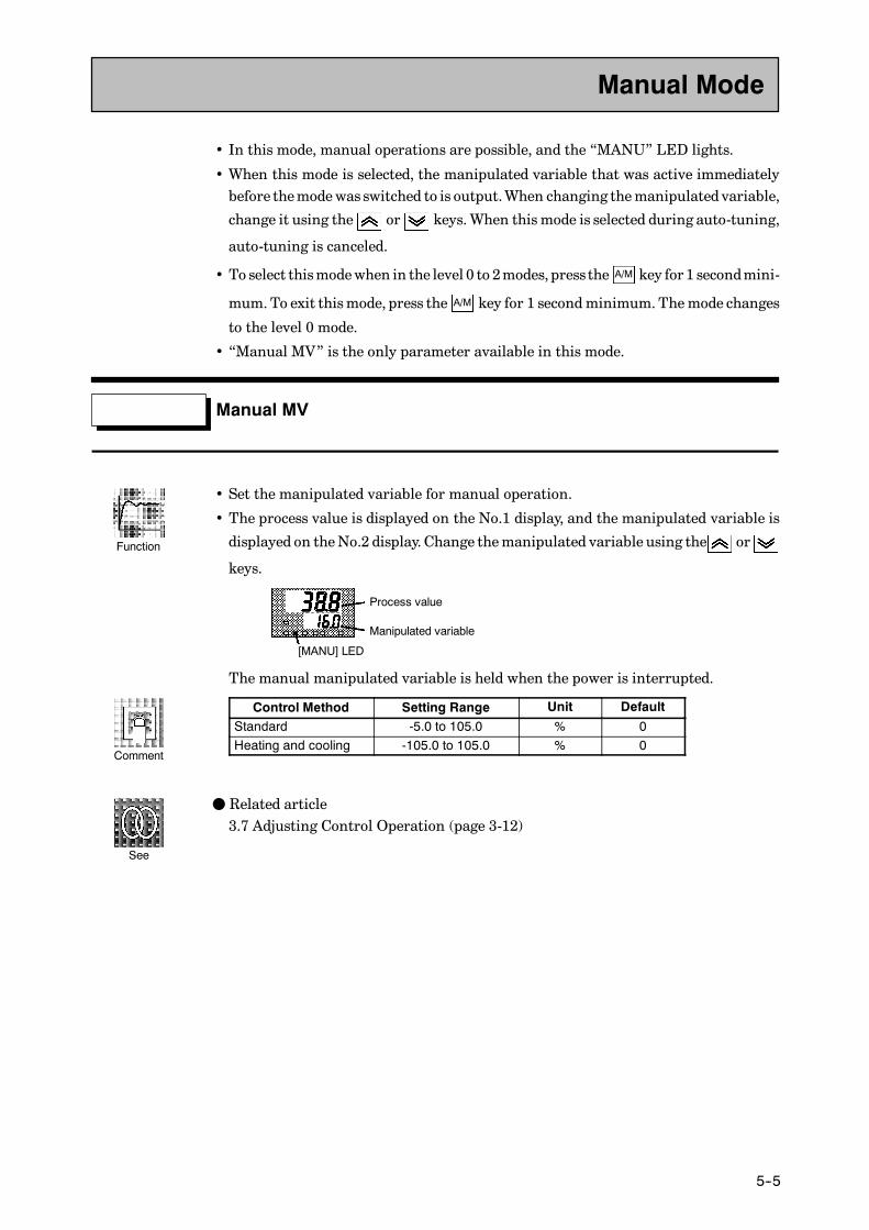
E5CK
5--5
• In this mode, manual operations are possible, and the “MANU” LED lights.
• When this mode is selected, the manipulated variable that was active immediatelybefore themodewas switched to is output.When changing themanipulated variable,
change it using the or keys. When this mode is selected during auto-tuning,
auto-tuning is canceled.
• To select thismodewhen in the level 0 to 2modes, press the A/M key for 1 secondmini-
mum.To exit thismode, press the A/M key for 1 secondminimum.Themode changes
to the level 0 mode.
• “Manual MV” is the only parameter available in this mode.
Manual MV
• Set the manipulated variable for manual operation.
• The process value is displayed on the No.1 display, and the manipulated variable is
displayed on theNo.2 display. Change themanipulated variable using the or
keys.
Process value
Manipulated variable
[MANU] LED
The manual manipulated variable is held when the power is interrupted.
Control Method Setting Range Unit Default
Standard -5.0 to 105.0 % 0Heating and cooling -105.0 to 105.0 % 0
F Related article3.7 Adjusting Control Operation (page 3-12)
Manual Mode
Function
Comment
See
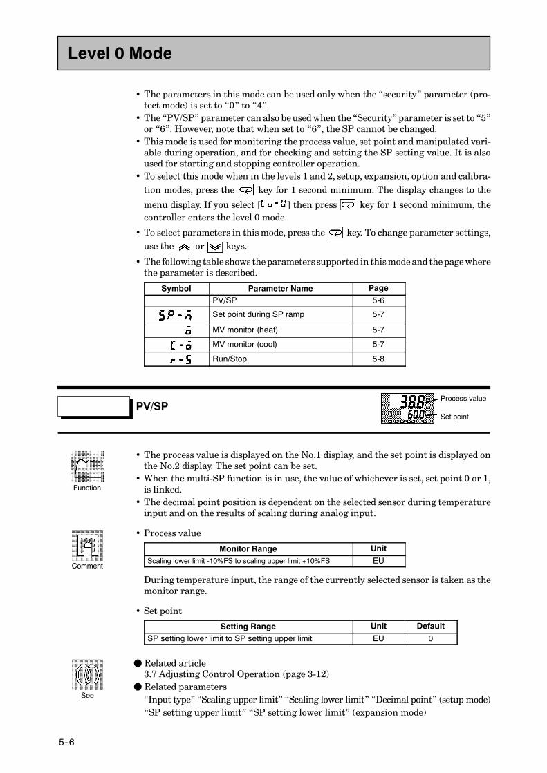
CHAPTER 5 PARAMETERS
E5CK
5--6
• The parameters in this mode can be used only when the “security” parameter (pro-tect mode) is set to “0” to “4”.
• The “PV/SP” parameter can also beusedwhen the “Security” parameter is set to “5”or “6”. However, note that when set to “6”, the SP cannot be changed.
• This mode is used for monitoring the process value, set point and manipulated vari-able during operation, and for checking and setting the SP setting value. It is alsoused for starting and stopping controller operation.
• To select this mode when in the levels 1 and 2, setup, expansion, option and calibra-tion modes, press the key for 1 second minimum. The display changes to the
menu display. If you select [ ] then press key for 1 second minimum, thecontroller enters the level 0 mode.
• To select parameters in this mode, press the key. To change parameter settings,use the or keys.
• The following table shows theparameters supported in thismodeand thepagewherethe parameter is described.
Symbol Parameter Name Page
PV/SP 5-6
Set point during SP ramp 5-7
MV monitor (heat) 5-7
MV monitor (cool) 5-7
Run/Stop 5-8
PV/SP
• The process value is displayed on the No.1 display, and the set point is displayed onthe No.2 display. The set point can be set.
• When the multi-SP function is in use, the value of whichever is set, set point 0 or 1,is linked.
• The decimal point position is dependent on the selected sensor during temperatureinput and on the results of scaling during analog input.
• Process value
Monitor Range UnitScaling lower limit -10%FS to scaling upper limit +10%FS EU
During temperature input, the range of the currently selected sensor is taken as themonitor range.
• Set point
Setting Range Unit Default
SP setting lower limit to SP setting upper limit EU 0
F Related article3.7 Adjusting Control Operation (page 3-12)
F Related parameters“Input type” “Scaling upper limit” “Scaling lower limit” “Decimal point” (setup mode)“SP setting upper limit” “SP setting lower limit” (expansion mode)
Level 0 Mode
Process value
Set point
Function
Comment
See
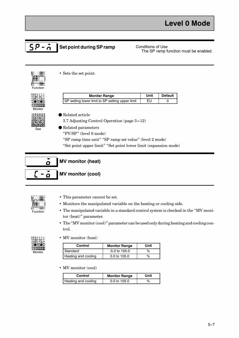
E5CK
5--7
Set point duringSPramp Conditions of UseThe SP ramp function must be enabled.
• Sets the set point.
Moniter Range Unit DefaultSP setting lower limit to SP setting upper limit EU 0
F Related article3.7 Adjusting Control Operation (page 3---12)
F Related parameters“PV/SP” (level 0 mode)“SP ramp time unit” “SP ramp set value” (level 2 mode)“Set point upper limit” “Set point lower limit (expansion mode)
MV monitor (heat)
MV monitor (cool)
• This parameter cannot be set.
• Monitors the manipulated variable on the heating or cooling side.
• Themanipulated variable in a standard control system is checked in the “MVmoni-tor (heat)” parameter.
• The“MVmonitor (cool)” parameter can beusedonlyduring heatingand cooling con-trol.
• MV monitor (heat)
Control Monitor Range Unit
Standard -5.0 to 105.0 %Heating and cooling 0.0 to 105.0 %
• MV monitor (cool)
Control Monitor Range Unit
Heating and cooling 0.0 to 105.0 %
Level 0 Mode
Function
Monitor
See
Function
Monitor

CHAPTER 5 PARAMETERS
E5CK
5--8
Run/Stop
• This parameter is used for checking the operating status of the controller, and forspecifying start and stop of operation.
• When the “run/stop” function is assigned to event input, “stop” is set when event in-put is ON, and “run” is set when event input isOFF. Parameter setting follows eventinput, even if attempting to change settings by key operation.
• To start operation, set this parameter to [ ] press the or keys. To stop
operation, set this parameter to [ ]. When operation is stopped, the “STOP”LED lights.
• Default is [ ]
F Related article3.6 Starting and Stopping Operation (page 3-11)
Level 0 Mode
Function
Exampleof use
See
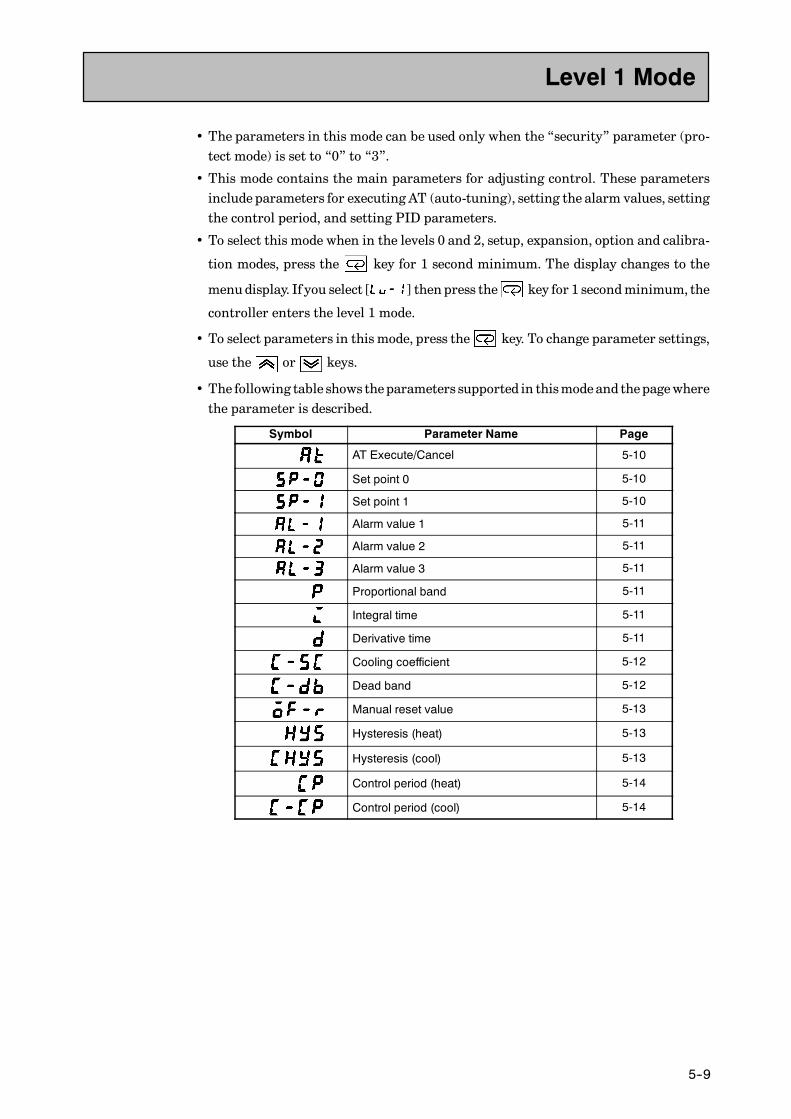
E5CK
5--9
• The parameters in this mode can be used only when the “security” parameter (pro-tect mode) is set to “0” to “3”.
• This mode contains the main parameters for adjusting control. These parametersinclude parameters for executing AT (auto-tuning), setting the alarm values, settingthe control period, and setting PID parameters.
• To select this mode when in the levels 0 and 2, setup, expansion, option and calibra-
tion modes, press the key for 1 second minimum. The display changes to the
menudisplay. If you select [ ] then press the key for 1 secondminimum, the
controller enters the level 1 mode.
• To select parameters in this mode, press the key. To change parameter settings,
use the or keys.
• The following table shows theparameters supported in thismodeand thepagewherethe parameter is described.
Symbol Parameter Name Page
AT Execute/Cancel 5-10
Set point 0 5-10
Set point 1 5-10
Alarm value 1 5-11
Alarm value 2 5-11
Alarm value 3 5-11
Proportional band 5-11
Integral time 5-11
Derivative time 5-11
Cooling coefficient 5-12
Dead band 5-12
Manual reset value 5-13
Hysteresis (heat) 5-13
Hysteresis (cool) 5-13
Control period (heat) 5-14
Control period (cool) 5-14
Level 1 Mode
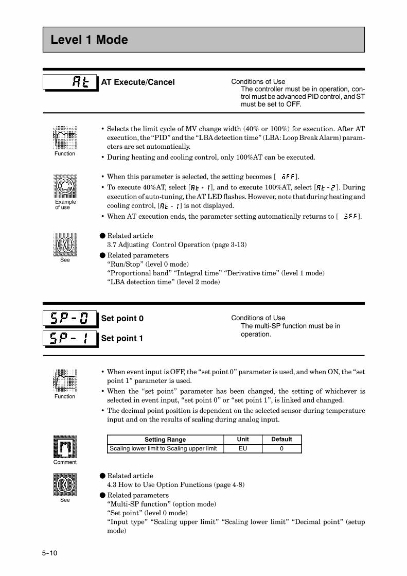
CHAPTER 5 PARAMETERS
E5CK
5--10
AT Execute/Cancel Conditions of UseThe controller must be in operation, con-trolmust beadvancedPIDcontrol, andSTmust be set to OFF.
• Selects the limit cycle of MV change width (40% or 100%) for execution. After ATexecution, the“PID”andthe “LBAdetection time” (LBA:LoopBreakAlarm)param-eters are set automatically.
• During heating and cooling control, only 100%AT can be executed.
• When this parameter is selected, the setting becomes [ ].
• To execute 40%AT, select [ ], and to execute 100%AT, select [ ]. Duringexecution of auto-tuning, theATLED flashes.However, note thatduring heatingandcooling control, [ ] is not displayed.
• When AT execution ends, the parameter setting automatically returns to [ ].
F Related article3.7 Adjusting Control Operation (page 3-13)
F Related parameters“Run/Stop” (level 0 mode)“Proportional band” “Integral time” “Derivative time” (level 1 mode)“LBA detection time” (level 2 mode)
Set point 0
Set point 1
Conditions of UseThe multi-SP function must be inoperation.
• When event input isOFF, the “set point 0” parameter is used, and whenON, the “setpoint 1” parameter is used.
• When the “set point” parameter has been changed, the setting of whichever isselected in event input, “set point 0” or “set point 1”, is linked and changed.
• The decimal point position is dependent on the selected sensor during temperatureinput and on the results of scaling during analog input.
Setting Range Unit Default
Scaling lower limit to Scaling upper limit EU 0
F Related article4.3 How to Use Option Functions (page 4-8)
F Related parameters“Multi-SP function” (option mode)“Set point” (level 0 mode)“Input type” “Scaling upper limit” “Scaling lower limit” “Decimal point” (setupmode)
Level 1 Mode
Function
Exampleof use
See
Function
Comment
See
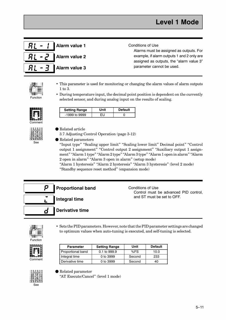
E5CK
5--11
Alarm value 1
Alarm value 2
Alarm value 3
Conditions of UseAlarms must be assigned as outputs. Forexample, if alarm outputs 1 and 2 only areassigned as outputs, the “alarm value 3”parameter cannot be used.
• This parameter is used for monitoring or changing the alarm values of alarm outputs1 to 3.
• During temperature input, the decimal point position is dependent on the currentlyselected sensor, and during analog input on the results of scaling.
Setting Range Unit Default
-1999 to 9999 EU 0
F Related article3.7 Adjusting Control Operation (page 3-12)
F Related parameters“Input type” “Scaling upper limit” “Scaling lower limit” Decimal point” “Controloutput 1 assignment” “Control output 2 assignment” “Auxiliary output 1 assign-ment” “Alarm1 type” “Alarm2 type”“Alarm3type” “Alarm1open in alarm”“Alarm2 open in alarm” “Alarm 3 open in alarm” (setup mode)“Alarm 1 hysteresis” “Alarm 2 hysteresis” “Alarm 3 hysteresis” (level 2 mode)“Standby sequence reset method” (expansion mode)
Proportional band
Integral time
Derivative time
Conditions of UseControl must be advanced PID control,and ST must be set to OFF.
• Sets thePIDparameters.However, note that thePIDparameter settings arechangedto optimum values when auto-tuning is executed, and self-tuning is selected.
Parameter Setting Range Unit Default
Proportional band 0.1 to 999.9 %FS 10.0Integral time 0 to 3999 Second 233Derivative time 0 to 3999 Second 40
F Related parameter“AT Execute/Cancel” (level 1 mode)
Level 1 Mode
Function
Comment
See
Function
Comment
See
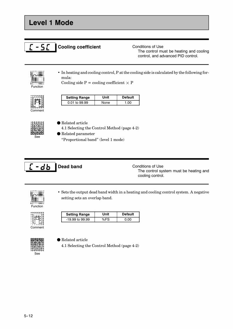
CHAPTER 5 PARAMETERS
E5CK
5--12
Cooling coefficient Conditions of UseThe control must be heating and coolingcontrol, and advanced PID control.
• In heating and cooling control, P at the cooling side is calculated by the following for-mula:Cooling side P = cooling coefficient¢ P
Setting Range Unit Default
0.01 to 99.99 None 1.00
F Related article4.1 Selecting the Control Method (page 4-2)
F Related parameter“Proportional band” (level 1 mode)
Dead band Conditions of UseThe control system must be heating andcooling control.
• Sets the output dead band width in a heating and cooling control system. A negativesetting sets an overlap band.
Setting Range Unit Default
-19.99 to 99.99 %FS 0.00
F Related article4.1 Selecting the Control Method (page 4-2)
Level 1 Mode
Function
Comment
See
Function
Comment
See
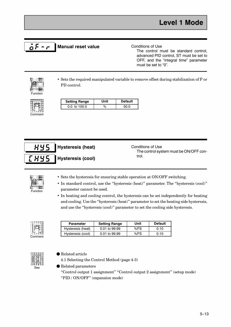
E5CK
5--13
Manual reset value Conditions of UseThe control must be standard control,advanced PID control, ST must be set toOFF, and the “integral time” parametermust be set to “0”.
• Sets the required manipulated variable to remove offset during stabilization of P orPD control.
Setting Range Unit Default
0.0 to 100.0 % 50.0
Hysteresis (heat)
Hysteresis (cool)
Conditions of UseThe control systemmust beON/OFF con-trol.
• Sets the hysteresis for ensuring stable operation at ON/OFF switching.
• In standard control, use the “hysteresis (heat)” parameter. The “hysteresis (cool)”parameter cannot be used.
• In heating and cooling control, the hysteresis can be set independently for heatingand cooling. Use the “hysteresis (heat)” parameter to set the heating side hysteresis,and use the “hysteresis (cool)” parameter to set the cooling side hysteresis.
Parameter Setting Range Unit DefaultHysteresis (heat) 0.01 to 99.99 %FS 0.10Hysteresis (cool) 0.01 to 99.99 %FS 0.10
F Related article4.1 Selecting the Control Method (page 4-3)
F Related parameters“Control output 1 assignment” “Control output 2 assignment” (setup mode)“PID / ON/OFF” (expansion mode)
Level 1 Mode
Function
Comment
Function
Comment
See
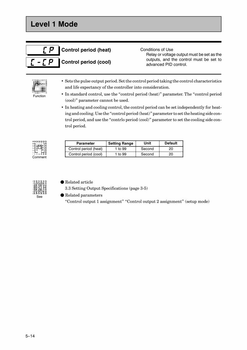
CHAPTER 5 PARAMETERS
E5CK
5--14
Control period (heat)
Control period (cool)
Conditions of UseRelay or voltage output must be set as theoutputs, and the control must be set toadvanced PID control.
• Sets the pulse output period. Set the control period taking the control characteristicsand life expectancy of the controller into consideration.
• In standard control, use the “control period (heat)” parameter. The “control period(cool)” parameter cannot be used.
• In heating and cooling control, the control period can be set independently for heat-ing and cooling.Use the “control period (heat)”parameter to set theheating sidecon-trol period, and use the “contrlo period (cool)” parameter to set the cooling side con-trol period.
Parameter Setting Range Unit Default
Control period (heat) 1 to 99 Second 20Control period (cool) 1 to 99 Second 20
F Related article3.3 Setting Output Specifications (page 3-5)
F Related parameters“Control output 1 assignment” “Control output 2 assignment” (setup mode)
Level 1 Mode
Function
Comment
See
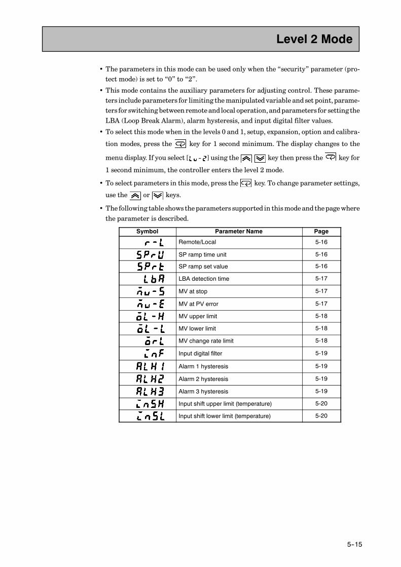
E5CK
5--15
• The parameters in this mode can be used only when the “security” parameter (pro-tect mode) is set to “0” to “2”.
• This mode contains the auxiliary parameters for adjusting control. These parame-ters include parameters for limiting themanipulated variable and set point, parame-ters for switching between remote and local operation,andparameters for setting theLBA (Loop Break Alarm), alarm hysteresis, and input digital filter values.
• To select this mode when in the levels 0 and 1, setup, expansion, option and calibra-
tion modes, press the key for 1 second minimum. The display changes to the
menu display. If you select [ ] using the key then press the key for
1 second minimum, the controller enters the level 2 mode.
• To select parameters in this mode, press the key. To change parameter settings,
use the or keys.
• The following table shows theparameters supported in thismodeand thepagewherethe parameter is described.
Symbol Parameter Name Page
Remote/Local 5-16
SP ramp time unit 5-16
SP ramp set value 5-16
LBA detection time 5-17
MV at stop 5-17
MV at PV error 5-17
MV upper limit 5-18
MV lower limit 5-18
MV change rate limit 5-18
Input digital filter 5-19
Alarm 1 hysteresis 5-19
Alarm 2 hysteresis 5-19
Alarm 3 hysteresis 5-19
Input shift upper limit (temperature) 5-20
Input shift lower limit (temperature) 5-20
Level 2 Mode

CHAPTER 5 PARAMETERS
E5CK
5--16
Remote/Local Conditions of UseThe communications function must be inuse.
• Switches between remote and local operation.
• To change the parameter setting during remote operation, use the communicationsfunction. To change the parameter setting during local operation, change the settingon the E5CK controller.
• You can check the parameter setting by both communications and on the E5CK con-troller regardless of whether the controller is switched to remote or local operation.
Setting Range Default
[ ]: remote / [ ]: local [ ]
SP ramp time unit
SP ramp set value
Conditions of UseST must be set to OFF.
• Specifies the change rate during SP ramp operation. Set the maximum permissiblechangewidth per unit of time (minute or hour) as the “SP ramp set value”.However,note that when set to “0”, the SP ramp function is disabled.
• The time unit and SP ramp set value are independent of each other. For example,when setting “30 perminute”, set the “SP ramp set value” parameter to “30” and the“SP ramp time unit” parameter to [ ] (“minute”). However, if you change the
time unit only to [ ] (“hour”), the set time becomes “30 per hour.”
• During temperature input, the decimal point position of the SP ramp set value isdependent on the currently selected sensor, and during analog input on the resultsof scaling.
Parameter Setting Range Unit Default
SP ramp time unit [ ]: minute/ [ ]: hour None
SP ramp set value 0 to 9999 EU 0
During temperature input, the range of the currently selected sensor it taken as thesetting range for the “SP ramp set value” parameter.
F Related article4.2 Operating Condition Restrictions (page 4-5)
F Related parameters“Input type” “Scaling upper limit” “Scaling lower limit” “Decimal point” (setupmode)
Level 2 Mode
Function
Comment
Function
Comment
See

E5CK
5--17
LBA detection time Conditions of UseThe LBA (Loop Break Alarm) functionmust be assigned as an output.
• This parameter is automatically set by AT execution.
• TheLBA is output if the changewidth of the process value falls below 0.2%full-scaleof the time preset to this parameter when themanipulated variable is set in the “MVupper limit” or “MV lower limit” parameters.
• The LBA function is disabled when this parameter is set to “0”.
Setting Range Unit Default
0 to 9999 Second 0
F Related article4.4 LBA (page 4-9)7.3 How to Use Error Output (page 7-5)
F Related parameters“AT Execute/Cancel” (level 1 mode)“Control output 1 assignment” “Control output 2 assignment” “Auxiliary output 1assignment” (setup mode)
MV at stop
MV at PV error
• The “MV at stop” parameter sets the manipulated variable when operation stops.
• The “MV at PV error” parameter sets themanipulated variable when an input erroroccurs.
• The setting ranges during standard control and heating and cooling control are differ-ent.
• The manipulated variable at the cooling side during heating and cooling control isexpressed as a negative value.
Control Method Setting Range Unit Default
Standard -5.0 to 105.0 % 0Heating and cooling -105.0 to 105.0 % 0
F Related articlesMV at stop : 3.6 Starting and Stopping Operation (page 3-11)MV at PV error : 7.2 How to Use the Error Display (page 7-3)
Level 2 Mode
Function
Comment
See
Function
Comment
See

CHAPTER 5 PARAMETERS
E5CK
5--18
MV upper limit
MV lower limit
MV change rate limit
Conditions of UseThe control must be advanced PID con-trol, and ST must be set to OFF.
• The“MVupper limit” and “MV lower limit” parameters set the upper and lower lim-its of the manipulated variable. When the manipulated variable calculated by theE5CK controller is outside of the upper-and lower-limit range, the upper limit orlower limit set to these parameters is output, respectively.
• The “MV change rate limit” parameter sets themaximumpermissible changewidthper second of the manipulated variable. If a change in the manipulated variablecauses this parameter setting to be exceeded, the calculated value is reached whilechanging the value by the per-second value set in this parameter.The “MV change rate limit” function is disabled when this parameter is set to “0.0”.
• MV upper limitThe setting ranges during standard control and heating and cooling control are dif-ferent. Also, themanipulated variable at the cooling side during heating and coolingcontrol is expressed as a negative value.
Control Method Setting Range Unit Default
Standard MV lower limit +0.1 to 105.0 % 105.0Heating and cooling 0.0 to 105.0 % 105.0
• MV lower limitThe setting ranges during standard control and heating and cooling control are dif-ferent. Also, themanipulated variable at the cooling side during heating and coolingcontrol is expressed as a negative value.
Control Method Setting Range Unit Default
Standard -5.0 to MV upper limit -0.1 % -5.0Heating and cooling -105.0 to 0.0 % -105.0
• MV change rate limit
Setting Range Unit Default
0.0 to 100.0 % 0.0
F Related article4.2 Operating Condition Restrictions (page 4-4)
Level 2 Mode
Function
Comment
See

E5CK
5--19
Input digital filter
• Sets the time constant of the input digital filter.The following figuresshows theeffecton data after passing through the digital filter.
A
PV before passing through filter
PV after passing through filter
0.63A
Input digital filter
Timeconstant Time
Setting Range Unit Default
0 to 9999 Second 0
Alarm 1 hysteresis
Alarm 2 hysteresis
Alarm 3 hysteresis
Conditions of UseAlarms must be assigned as outputs. Forexample, if alarm outputs 1 and 2 only areassigned as outputs, the “alarm 3hystere-sis” parameter cannot be used.
• This parameter is for checking the hysteresis of alarm outputs 1 to 3.
Setting Range Unit Default
0.01 to 99.99 %FS 0.02
F Related article3.4 Setting Alarm Type (page 3-7)
F Related parameters“Alarm1 type” “Alarm2 type”“Alarm3type” “Alarm1open in alarm”“Alarm2openin alarm” “Alarm 3 open in alarm” (setup mode)“Alarm value 1” “Alarm value 2” “Alarm value 3” (level 1 mode)
Level 2 Mode
Function
Comment
Function
Comment
See
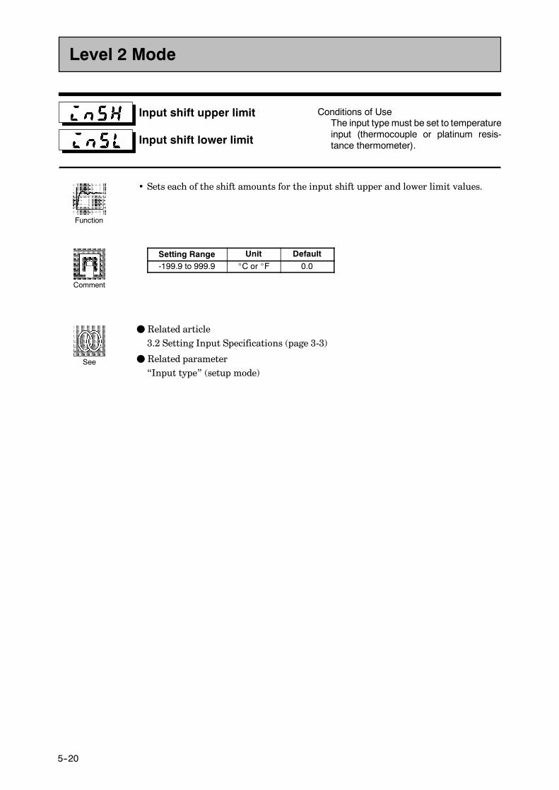
CHAPTER 5 PARAMETERS
E5CK
5--20
Input shift upper limit
Input shift lower limit
Conditions of UseThe input type must be set to temperatureinput (thermocouple or platinum resis-tance thermometer).
• Sets each of the shift amounts for the input shift upper and lower limit values.
Setting Range Unit Default-199.9 to 999.9 _C or _F 0.0
F Related article3.2 Setting Input Specifications (page 3-3)
F Related parameter“Input type” (setup mode)
Level 2 Mode
Function
Comment
See

E5CK
5--21
• The parameters in this mode can be used only when the “security” parameter (pro-tect mode) is set to “0” and “1”.
• This mode contains the parameters for setting the basic specifications of the E5CKcontroller. These parameters include parameters for specifying the input type, scal-ing, output assignments, and direct/reverse operation.
• To select thismodewhen in the levels 0 to 2,expansion, optionand calibrationmodes,
press the key for 1 second minimum. The display changes to the menu display.
If you select [ ] using the key then press the key for 1 secondmini-
mum, the controller enters the setup mode.
• To select parameters in this mode, press the key. To change parameter settings,
use the or keys.
• The following table shows theparameters supported in thismodeand thepagewherethe parameter is described.
Symbol Parameter Name Page
Input type 5-22
Scaling upper limit 5-23
Scaling lower limit 5-23
Decimal point 5-23
_C/_F selection 5-24
Parameter initialize 5-23
Control output 1 assignment 5-24
Control output 2 assignment 5-24
Auxiliary output 1 assignment 5-25
Alarm 1 type 5-25
Alarm 1 open in alarm 5-26
Alarm 2 type 5-25
Alarm 2 open in alarm 5-26
Alarm 3 type 5-25
Alarm 3 open in alarm 5-26
Direct/Reverse operation 5-26
Setup Mode

CHAPTER 5 PARAMETERS
E5CK
5--22
Input type
• Match the setting (software) of this parameter with the setting (hardware) of theinput type jumper connector.
• Set the input types to be connected to terminal Nos. 6 to 8 by the input type codes inthe table below.
• Set the code according to the following table. Default is “2: K1 thermocouple”.
Set value Input Type Jumper Position
0 JPt -199.9 to 650.0 (_C) /-199.9 to 999.9 (_F) Platinum resis-TC PT1 Pt -199.9 to 650.0 (_C) /-199.9 to 999.9 (_F)
Platinum resistance thermometer TC⋅PT
2 K1 -200 to 1300 (_C) /-300 to 2300 (_F)3 K2 0.0 to 500.0 (_C) /0.0 to 900.0 (_F)4 J1 -100 to 850 (_C) /-100 to 1500 (_F)5 J2 0.0 to 400.0 (_C) /0.0 to 750.0 (_F)6 T -199.9 to 400.0 (_C) /-199.9 to 700.0 (_F)7 E 0 to 600 (_C) /0 to 1100 (_F)8 L1 -100 to 850 (_C) /-100 to 1500 (_F)9 L2 0.0 to 400.0 (_C) /0.0 to 750.0 (_F) Thermocouple TC⋅PT10 U -199.9 to 400.0 (_C) /-199.9 to 700.0 (_F)
Thermocouple TC⋅PT
11 N -200 to 1300 (_C) /-300 to 2300 (_F)12 R 0 to 1700 (_C) /0 to 3000 (_F)13 S 0 to 1700 (_C) /0 to 3000 (_F)14 B 100 to 1800 (_C) /300 to 3200 (_F)15 W 0 to 2300 (_C) /0 to 4100 (_F)16 PLII 0 to 1300 (_C) /0 to 2300 (_F)17 4 to 20mA
Current input I18 0 to 20mACurrent input I
19 1 to 5V20 0 to 5V Voltage input V21 0 to 10V
Voltage input V
F Related article3.2 Setting Input Specifications (page 3-3)
F Related parametersWhen input type is set to temperature input:“_C/_F selection” (setup mode)When input type is set to voltage input or current input:“Scaling upper limit” “Scaling lower limit” “Decimal point” (setup mode)
Setup Mode
Function
Comment
See

E5CK
5--23
Scaling upper limit
Scaling lower limit
Decimal point
Conditions of UseThe input type must be set to analog input(voltage or current input).
• This parameter can be used only when voltage input or current input is selected asthe input type.
• When voltage input or current input is selected as the input type, scaling is carriedout. Set the scaling upper limit in the “scaling upper limit” parameter and thescalinglower limit in the “scaling lower limit” parameter.
• The “decimal point” parameter specifies the decimal point position of parameters(set point, etc.) whose unit is set to EU (Engineering Unit).
• Scaling upper limit, Scaling lower limit
Parameter Setting Range Unit DefaultScaling upper limit Scaling lower limit +1 to 9999 EU 100Scaling lower limit -1999 to scaling upper limit -1 EU 0
• Decimal point : default : 0
Set Value Setting Example
0123
0 digits past decimal point1 digit past decimal point2 digits past decimal point3 digits past decimal point
1234123.412.341.234
F Related article3.2 Setting Input Specifications (page 3-3)
F Related parameter“Input type” (setup mode)
Parameter initialize
• Returns parameter settings to their defaults. However, note that the followingparameters are not affected by execution of this parameter:“input type”, “scaling upper limit”, “scaling lower limit”, “decimal point” and“_C/_F selection”.
• When this parameter is selected, [ ] (“no”) is first displayed.To initializeparame-
ters, press the key to specify [ ] (“yes”).
Setup Mode
Function
Comment
See
Function
Exampleof use
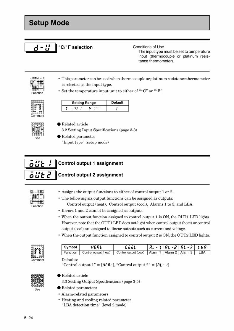
CHAPTER 5 PARAMETERS
E5CK
5--24
_C/_F selection Conditions of UseThe input type must be set to temperatureinput (thermocouple or platinum resis-tance thermometer).
• This parameter can beusedwhen thermocouple orplatinumresistancethermometeris selected as the input type.
• Set the temperature input unit to either of “_C” or “_F”.
Setting Range Default
: _C / : _F
F Related article3.2 Setting Input Specifications (page 3-3)
F Related parameter“Input type” (setup mode)
Control output 1 assignment
Control output 2 assignment
• Assigns the output functions to either of control output 1 or 2.
• The following six output functions can be assigned as outputs:Control output (heat), Control output (cool), Alarms 1 to 3, and LBA.
• Errors 1 and 2 cannot be assigned as outputs.
• When the output function assigned to control output 1 is ON, the OUT1 LED lights.However, note that the OUT1 LEDdoes not light when control output (heat) or controloutput (cool) are assigned to linear outputs such as current and voltage.
• When the output function assigned to control output 2 is ON, the OUT2 LED lights.
Symbol
Function Control output (heat) Control output (cool) Alarm 1 Alarm 2 Alarm 3 LBA
Defaults:“Control output 1” = [ ], “Control output 2” = [ ]
F Related article3.3 Setting Output Specifications (page 3-5)
F Related parameters
• Alarm-related parameters• Heating and cooling related parameter“LBA detection time” (level 2 mode)
Setup Mode
Function
Comment
See
Function
Comment
See
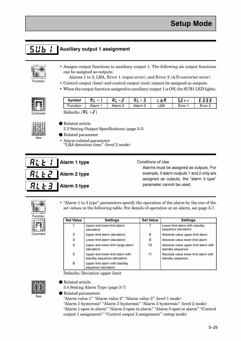
E5CK
5--25
Auxiliary output 1 assignment
• Assigns output functions to auxiliary output 1. The following six output functionscan be assigned as outputs:Alarms 1 to 3, LBA, Error 1 (input error), and Error 2 (A/D converter error).
• Control output (heat) and control output (cool) cannot be assigned as outputs.• When theoutput function assigned to auxiliary output 1 isON, theSUB1 LED lights.
Symbol
Function Alarm 1 Alarm 2 Alarm 3 LBA Error 1 Error 2
Defaults: [ ]
F Related article3.3 Setting Output Specifications (page 3-5)
F Related parameter• Alarm-related parameter“LBA detection time” (level 2 mode)
Alarm 1 type
Alarm 2 type
Alarm 3 type
Conditions of UseAlarms must be assigned as outputs. Forexample, if alarm outputs 1 and 2 only areassigned as outputs, the ”alarm 3 type”parameter cannot be used.
• “Alarm 1 to 3 type” parameters specify the operation of the alarm by the one of theset values in the following table. For details of operation at an alarm, see page 3-7.
Set Value Settings Set Value Settings1 Upper-and lower-limit alarm
(deviation)7 Lower-limit alarm with standby
sequence (deviation)
2 Upper-limit alarm (deviation) 8 Absolute-value upper-limit alarm
3 Lower-limit alarm (deviation) 9 Absolute-value lower-limit alarm
4 Upper-and lower-limit range alarm(deviation)
10 Absolute-value upper-limit alarm withstandby sequence
5 Upper-and lower-limit alarm withstandby sequence (deviation)
11 Absolute-value lower-limit alarm withstandby sequence
6 Upper-limit alarm with standbysequence (deviation)
Defaults: Deviation upper limit
F Related article3.4 Setting Alarm Type (page 3-7)
F Related parameters“Alarm value 1” “Alarm value 2” “Alarm value 3” (level 1 mode)“Alarm 1 hysteresis” “Alarm 2 hysteresis” “Alarm 3 hysteresis” (level 2 mode)“Alarm 1 open in alarm” “Alarm 2 open in alarm” “Alarm 3 open in alarm” “Controloutput 1 assignment” “Control output 2 assignment” (setup mode)
Setup Mode
Function
Comment
See
Function
Comment
See
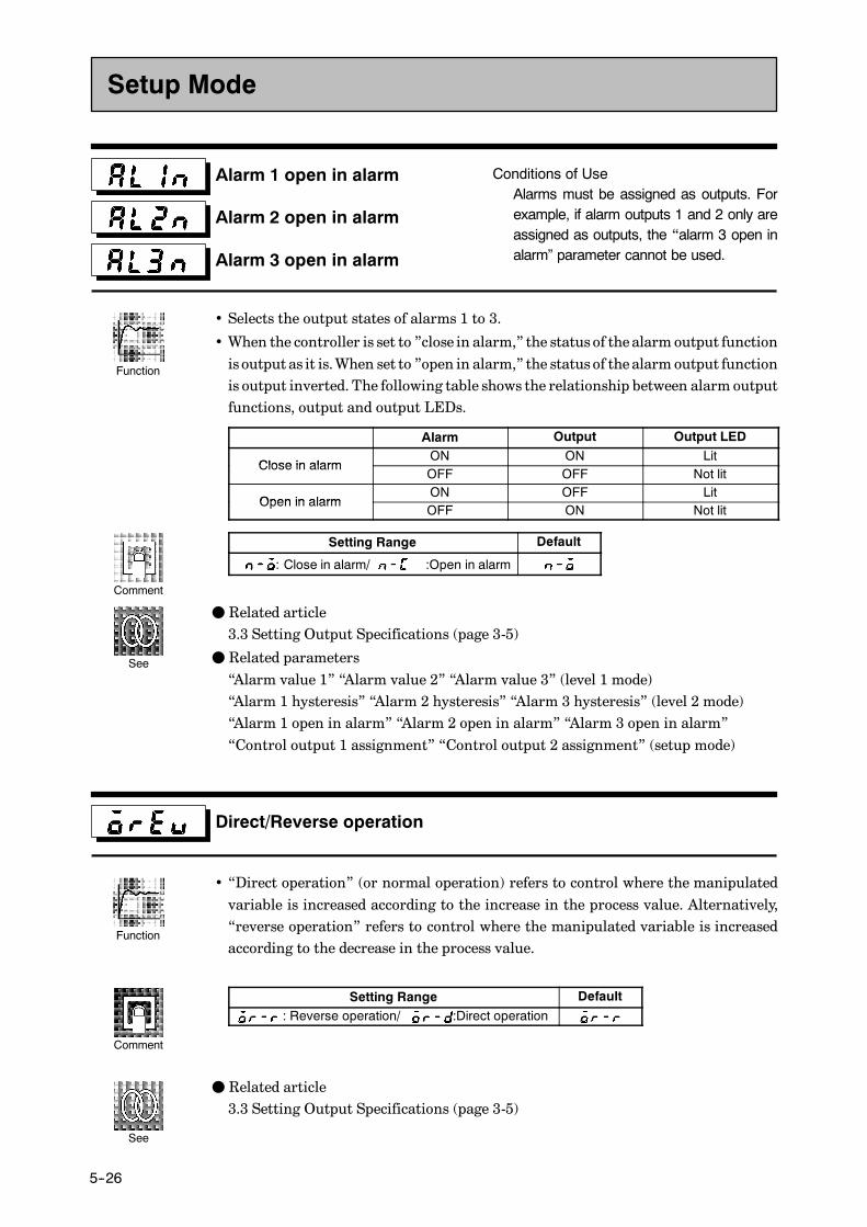
CHAPTER 5 PARAMETERS
E5CK
5--26
Alarm 1 open in alarm
Alarm 2 open in alarm
Alarm 3 open in alarm
Conditions of UseAlarms must be assigned as outputs. Forexample, if alarm outputs 1 and 2 only areassigned as outputs, the “alarm 3 open inalarm” parameter cannot be used.
• Selects the output states of alarms 1 to 3.
• When the controller is set to ”close in alarm,” the status of the alarm output functionis output as it is.When set to ”open in alarm,” the status of the alarm output functionis output inverted. The following table shows the relationship between alarm outputfunctions, output and output LEDs.
Alarm Output Output LED
Close in alarmON ON Lit
Close in alarmOFF OFF Not lit
Open in alarmON OFF Lit
Open in alarmOFF ON Not lit
Setting Range Default
: Close in alarm/ :Open in alarm
F Related article3.3 Setting Output Specifications (page 3-5)
F Related parameters“Alarm value 1” “Alarm value 2” “Alarm value 3” (level 1 mode)“Alarm 1 hysteresis” “Alarm 2 hysteresis” “Alarm 3 hysteresis” (level 2 mode)“Alarm 1 open in alarm” “Alarm 2 open in alarm” “Alarm 3 open in alarm”“Control output 1 assignment” “Control output 2 assignment” (setup mode)
Direct/Reverse operation
• “Direct operation” (or normal operation) refers to control where the manipulatedvariable is increased according to the increase in the process value. Alternatively,“reverse operation” refers to control where the manipulated variable is increasedaccording to the decrease in the process value.
Setting Range Default
: Reverse operation/ :Direct operation
F Related article3.3 Setting Output Specifications (page 3-5)
Setup Mode
Function
Comment
See
Function
Comment
See
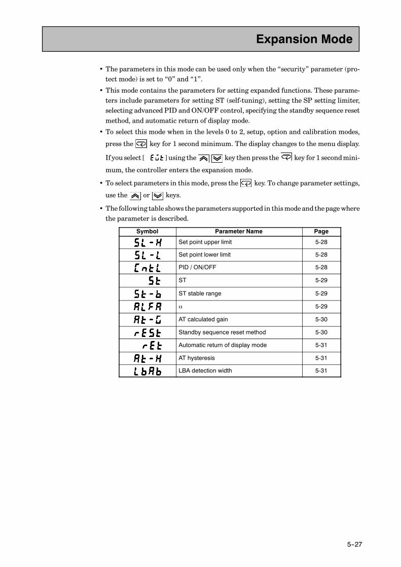
E5CK
5--27
• The parameters in this mode can be used only when the “security” parameter (pro-tect mode) is set to “0” and “1”.
• This mode contains the parameters for setting expanded functions. These parame-ters include parameters for setting ST (self-tuning), setting the SP setting limiter,selecting advanced PID andON/OFF control, specifying the standby sequence resetmethod, and automatic return of display mode.
• To select this mode when in the levels 0 to 2, setup, option and calibration modes,
press the key for 1 second minimum. The display changes to the menu display.
If you select [ ] using the key then press the key for 1 secondmini-
mum, the controller enters the expansion mode.
• To select parameters in this mode, press the key. To change parameter settings,
use the or keys.
• The following table shows theparameters supported in thismodeand thepagewherethe parameter is described.
Symbol Parameter Name Page
Set point upper limit 5-28
Set point lower limit 5-28
PID / ON/OFF 5-28
ST 5-29
ST stable range 5-29
α 5-29
AT calculated gain 5-30
Standby sequence reset method 5-30
Automatic return of display mode 5-31
AT hysteresis 5-31
LBA detection width 5-31
Expansion Mode

CHAPTER 5 PARAMETERS
E5CK
5--28
Set point upper limit
Set point lower limit
• Limits the upper and lower limits of the set point.When the set point exceeds the set-tings of the “Set point upper limit” and“Set point lower limit”parameters, theE5CKcontroller regards the settings of the “Set point upper limit” and “Set point lowerlimit” parameters as the set points.
• When the input type is changed to temperature input, the set point upper and lowerlimits are changed to the upper and lower limits of the currently selected sensor. Andwhen the input type is changed to analog input, the set point upper and lower limitsare changed to the scaling upper and lower limits.
• During temperature input, the decimal point position is dependent on the currentlyselected sensor, and during analog input on the results of scaling.
Parameter Setting Range Unit Default
SP setting upper limit SP setting lower limit +1 to scaling upper limit EU 1300SP setting lower limit Scaling lower limit to SP setting upper limit -1 EU -200
During temperature input, the range becomes the range of use of the selected sensorinstead of the scaling upper and lower limit values.
F Related article4.2 Operating Condition Restrictions (page 4-5)
F Related parameters“Input type” “Scaling upper limit” “Scaling lower limit” “Decimal point” (setupmode)
PID / ON/OFF
• Selects advanced PID control or ON/OFF control.
Setting Range Default
: advance PID/ :ON/OFF
F Related article4.1 Selecting the Control Method (page 4-3)
F Related parameters“Hysteresis (heat)” “Hysteresis (cool)” (level 1 mode)
Expansion Mode
Function
Comment
See
Function
Comment
See

E5CK
5--29
ST
ST stable range
Conditions of UseThe input type must be set to temperatureinput, and the control must be either stan-dard control or advanced PID control.
• When the “ST”parameter is set to “ON”, the self-tuning (ST) function is active.Dur-ing operation of the ST function, the power on the load side connected to the controloutput must be turned ON at the same time or before start of E5CK operation.
• The “ST stable range” parameter sets the stable range width during self-tuning.However, note that this parameter cannot be usedwhen the “ST” parameter is set to“OFF”.
Parameter Setting Range Unit Default
ST : ST function OFF/ : ST function ON NoneST stable range 0.1 to 999.9 _C or _F 15.0
F Related articleFuzzy self-tuning (page A-10)
F Related parameters“Input type” (setup mode)“PID / ON/OFF” (expansion mode)
α Conditions of UseThe control must be advanced PID con-trol, and ST must be set to OFF.
• Sets advanced PID-control parameter α.
Setting Range Unit Default
0.00 to 1.00 None 0.65
F Related parameter“PID / ON/OFF” (expansion mode)
Expansion Mode
Function
Comment
See
Function
Comment
See
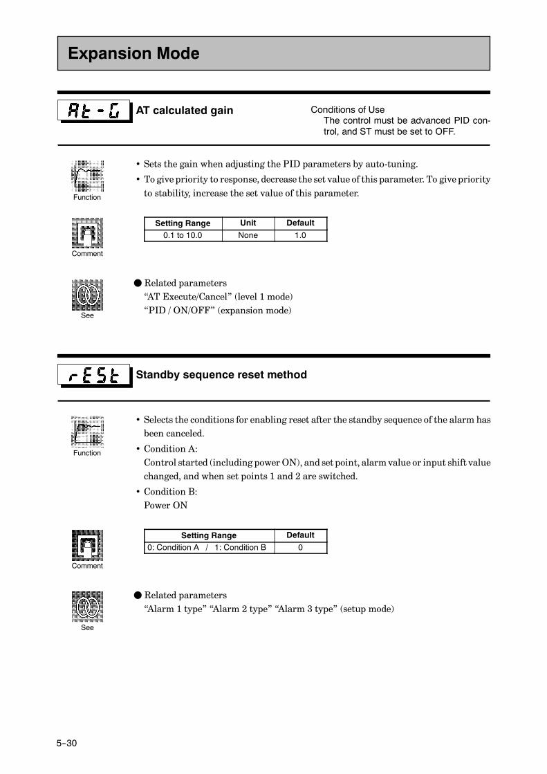
CHAPTER 5 PARAMETERS
E5CK
5--30
AT calculated gain Conditions of UseThe control must be advanced PID con-trol, and ST must be set to OFF.
• Sets the gain when adjusting the PID parameters by auto-tuning.
• To give priority to response, decrease the set value of this parameter. To give priorityto stability, increase the set value of this parameter.
Setting Range Unit Default
0.1 to 10.0 None 1.0
F Related parameters“AT Execute/Cancel” (level 1 mode)“PID / ON/OFF” (expansion mode)
Standby sequence reset method
• Selects the conditions for enabling reset after the standby sequence of the alarm hasbeen canceled.
• Condition A:Control started (including power ON), and set point, alarmvalue or input shift valuechanged, and when set points 1 and 2 are switched.
• Condition B:Power ON
Setting Range Default
0: Condition A / 1: Condition B 0
F Related parameters“Alarm 1 type” “Alarm 2 type” “Alarm 3 type” (setup mode)
Expansion Mode
Function
Comment
See
Function
Comment
See
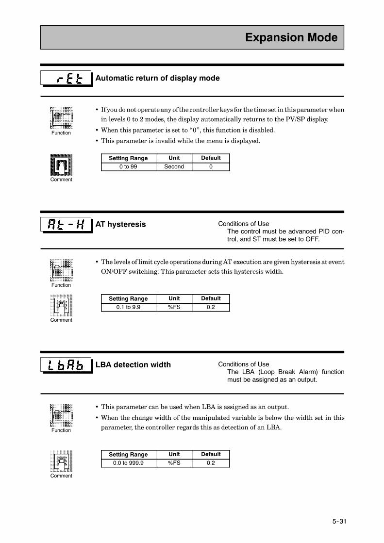
E5CK
5--31
Automatic return of display mode
• If youdonot operateany of the controllerkeys for the timeset in this parameterwhenin levels 0 to 2 modes, the display automatically returns to the PV/SP display.
• When this parameter is set to “0”, this function is disabled.
• This parameter is invalid while the menu is displayed.
Setting Range Unit Default
0 to 99 Second 0
AT hysteresis Conditions of UseThe control must be advanced PID con-trol, and ST must be set to OFF.
• The levels of limit cycle operations during AT execution are given hysteresis at eventON/OFF switching. This parameter sets this hysteresis width.
Setting Range Unit Default
0.1 to 9.9 %FS 0.2
LBA detection width Conditions of UseThe LBA (Loop Break Alarm) functionmust be assigned as an output.
• This parameter can be used when LBA is assigned as an output.
• When the change width of the manipulated variable is below the width set in thisparameter, the controller regards this as detection of an LBA.
Setting Range Unit Default
0.0 to 999.9 %FS 0.2
Expansion Mode
Function
Comment
Function
Comment
Function
Comment

CHAPTER 5 PARAMETERS
E5CK
5--32
• The parameters in this mode can be used only when the “security” parameter (pro-tect mode) is set to “0” and “1”.
• You can select this mode only when the option unit is set in the controller. In thismode, you can set the communications conditions, transfer output and event inputparameters to match the type of option unit set in the controller.
• To select thismodewhen in the levels 0 to 2, setup, expansion and calibrationmodes,
press the key for 1 second minimum. The display changes to the menu display.
If you select [ ] using the key then press the key for 1 secondmini-
mum, the controller enters the option mode.
• To select parameters in this mode, press the key. To change parameter settings,
use the or keys.
• The following table shows theparameters supported in thismodeand thepagewherethe parameter is described.
Symbol Parameter Name Page
Multi-SP function 5-33
Event input assignment 1 5-33
Communication stop bit 5-34
Communication data length 5-34
Communication parity 5-34
Communication baud rate 5-34
Communication unit No. 5-34
Transfer output type 5-35
Transfer output upper limit 5-35
Transfer output lower limit 5-35
Option Mode

E5CK
5--33
Multi-SP function Conditions of UseThe event input function must be in use.
• Thisparameter specifies thenumberof setpoints (SP)whenusing themulti-SP func-tion. When set to “0”, the multi-SP function cannot be used.
Setting Range Unit Default
0 to 1 None 0
F Related article4.3 How to Use Option Functions (4-7)
F Related parameter“Event input assignment 1” (option mode)
F Option unitEvent input unit (E53-CKB)
Event input assignment 1 Conditions of UseEvent input must be specified when theevent input function is in use.
• Thisparameter specifiesevent inputother than themulti-SP function.Thefollowingtwo functions can be specified:Run/Stop and Manual/Auto.
• Event input is disabled while the menu is displayed.It is also disabled in set up, expantion, option and calibration modes.
Symbol Function Event Input Operation
Run/Stop ON: Stop, OFF : Run
Manual/Auto ON: Manual, OFF : Auto
F Related article4.3 How to Use Option Functions (page 4-7)
F Related parameter“Event input assignment 1” (option mode)
F Option unitEvent input unit (E53-CKB)
Option Mode
Function
Comment
See
Model
Function
Comment
See
Model
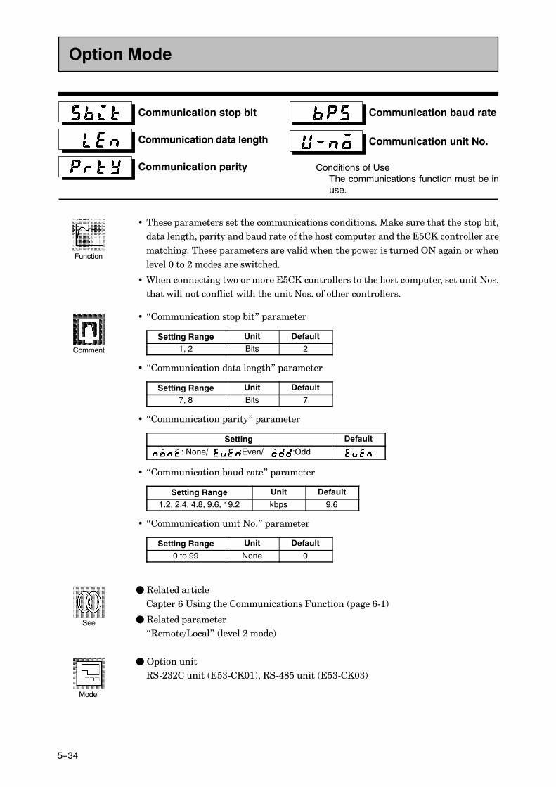
CHAPTER 5 PARAMETERS
E5CK
5--34
Communication stop bit
Communication data length
Communication parity
Communication baud rate
Communication unit No.
Conditions of UseThe communications function must be inuse.
• These parameters set the communications conditions. Make sure that the stop bit,data length, parity and baud rate of the host computer and the E5CK controller arematching. These parameters are valid when the power is turned ON again or whenlevel 0 to 2 modes are switched.
• When connecting two or more E5CK controllers to the host computer, set unit Nos.that will not conflict with the unit Nos. of other controllers.
• “Communication stop bit” parameter
Setting Range Unit Default1, 2 Bits 2
• “Communication data length” parameter
Setting Range Unit Default
7, 8 Bits 7
• “Communication parity” parameter
Setting Default
: None/ :Even/ :Odd
• “Communication baud rate” parameter
Setting Range Unit Default
1.2, 2.4, 4.8, 9.6, 19.2 kbps 9.6
• “Communication unit No.” parameter
Setting Range Unit Default
0 to 99 None 0
F Related articleCapter 6 Using the Communications Function (page 6-1)
F Related parameter“Remote/Local” (level 2 mode)
F Option unitRS-232C unit (E53-CK01), RS-485 unit (E53-CK03)
Option Mode
Function
Comment
See
Model

E5CK
5--35
Transfer output type
Transfer output upper limit
Transfer output lower limit
Conditions of UseThe transfer output function must be inuse.
• These parameters set the transfer output conditions.
• The“transfer output type” parameter selects one of the following as the transfer out-put type, and assigns this to transfer output:Set point, Set point during SP ramp, Process value,Manipulated variable (heat), andManipulated variable (cool).However, note that “manipulated variable (cool)” canbe selectedonly duringheatingand cooling control.
• The “transfer output upper limit” and “transfer output lower limit” parameters areused for scaling of transfer output. The setting range varies according to this outputdata. Also, a lower limit value larger than the upper limit value may be set.
• During temperature input, the decimal point position of the set point, set point dur-ing SP ramp or process value is dependent on the currently selected sensor, and dur-ing analog input on the results of scaling.
Transfer Type Transfer Output Lower Limit toTransfer Output Upper Limit
Set point Set point lower limit value to Set point upper limit value
Set point during SP ramp Set point lower limit value to Set point upper limit value
Process value Scaling lower limit to scaling upper limit
Manipulated variable (heat) -5.0% to 105.0%
Manipulated variable (cool) 0.0% to 105.0%
• The output ranges of the set point, set point during SP ramp or process value whentemperature input is selected are the ranges supported by the selected sensor.
• When you have selected the “manipulated variable (heat)” parameter, the transferoutput lower limit during heating and cooling control becomes “0.0”.
F Related article4.3 How to Use Option Functions (page 4-8)
F Option unitTransfer output unit (E53-CKF)
Option Mode
Function
Comment
See
Model

CHAPTER 5 PARAMETERS
E5CK
5--36
• The parameters in this mode can be used only when the “security” parameter (pro-tect mode) is set to “0”. When selecting this mode for the first time after the E5CKhas left the factory, return the “security” parameter to “0”.
• This mode contains the parameters for user calibration of inputs and outputs. Onlyparameters relating to input types specified in the “input type” parameter (setupmode) can be used. Also, related output parameters can be used only when the com-munications unit (E53-CKF) is added on.
• To select thismodewhen in the levels0 to2, setup,expansion andoptionmodes,press
the key for 1 second minimum. The display changes to the menu display. If you
select [ ] using the key then press the key for 1 secondminimum,
the controller enters the calibration mode.
• For details on parameters in the calibration mode, see 4.5 Calibration (page 4-11).
Calibration Mode
CHAPTER 6 USING THE COMMUNICATIONS FUNCTION
6--1
CHAPTER 6USING THECOMMUNICATIONSFUNCTION
This chapter mainly describes communications with a host computerand communications commands.
CHAPTER6
6.1 Outline ofthe Communications Function 6---2. . . . . . . . . .
Outline 6---2. . . . . . . . . . . . . . . . . . . . . . . . . . . . . . .
Transfer procedure 6---2. . . . . . . . . . . . . . . . . . . . .
Interface 6---2. . . . . . . . . . . . . . . . . . . . . . . . . . . . . .
6.2 Preparing for Communications 6---3. . . . . . . . . .
Cable connections 6---3. . . . . . . . . . . . . . . . . . . . . .
Setting the communicationsspecifications 6---4. . . . . . . . . . . . . . . . . . . . . . . . . .
6.3 Command Configuration 6---5. . . . . . . . . . . . . . . .
6.4 Commands and Responses 6---6. . . . . . . . . . . . . .
Reading/writing parameters 6---6. . . . . . . . . . . . .
Issuing special commands 6---9. . . . . . . . . . . . . . .
6.5 How to Read CommunicationsError Information 6---10. . . . . . . . . . . . . . . . . . . . .
Undefined error 6---11. . . . . . . . . . . . . . . . . . . . . . . .
6.6 Program Example 6---12. . . . . . . . . . . . . . . . . . . . . .
How to use programs 6---12. . . . . . . . . . . . . . . . . . .
Program list (language: IBM PC) 6---13. . . . . . . .
Examples of use 6---14. . . . . . . . . . . . . . . . . . . . . . . .
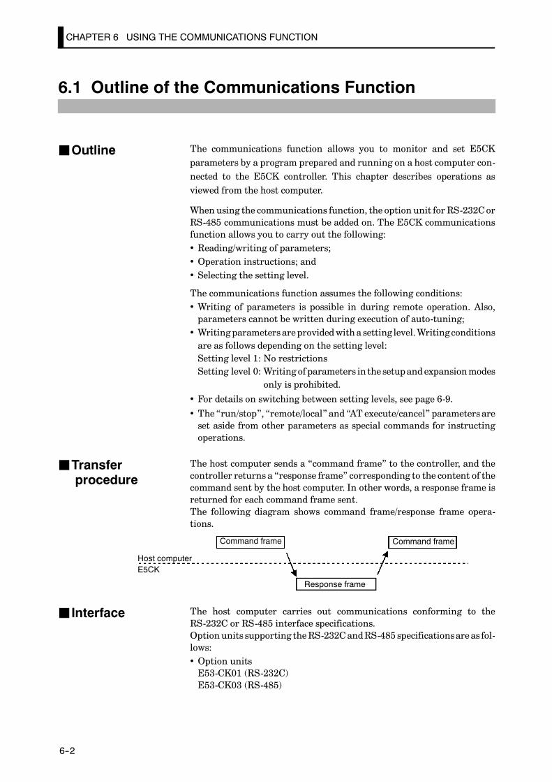
CHAPTER 6 USING THE COMMUNICATIONS FUNCTION
E5CK
6--2
6.1 Outline of the Communications Function
The communications function allows you to monitor and set E5CKparameters by a program prepared and running on a host computer con-nected to the E5CK controller. This chapter describes operations asviewed from the host computer.
When using the communications function, the option unit for RS-232CorRS-485 communications must be added on. The E5CK communicationsfunction allows you to carry out the following:• Reading/writing of parameters;• Operation instructions; and• Selecting the setting level.
The communications function assumes the following conditions:• Writing of parameters is possible in during remote operation. Also,parameters cannot be written during execution of auto-tuning;
• Writing parameters areprovidedwith a setting level.Writing conditionsare as follows depending on the setting level:Setting level 1: No restrictionsSetting level 0: Writing of parameters in the setupandexpansionmodes
only is prohibited.
• For details on switching between setting levels, see page 6-9.
• The“run/stop”, “remote/local” and “AT execute/cancel” parameters areset aside from other parameters as special commands for instructingoperations.
The host computer sends a “command frame” to the controller, and thecontroller returns a “response frame” corresponding to the content of thecommand sent by the host computer. In other words, a response frame isreturned for each command frame sent.The following diagram shows command frame/response frame opera-tions.
Command frame Command frame
Response frame
Host computerE5CK
The host computer carries out communications conforming to theRS-232C or RS-485 interface specifications.Option units supporting theRS-232CandRS-485 specificationsare as fol-lows:• Option unitsE53-CK01 (RS-232C)E53-CK03 (RS-485)
JOutline
JTransferprocedure
J Interface
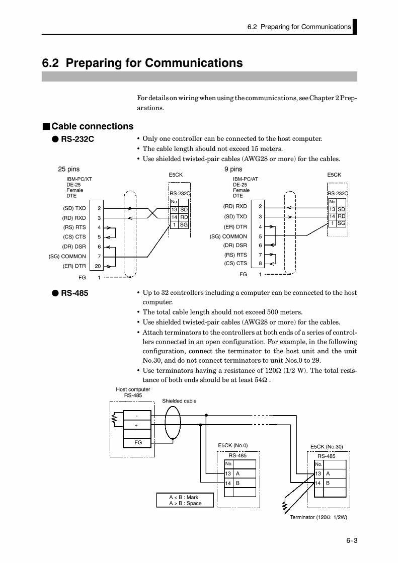
6.2 Preparing for Communications
E5CK
6--3
6.2 Preparing for Communications
Fordetailsonwiringwhenusing thecommunications, seeChapter 2Prep-arations.
JCable connections• Only one controller can be connected to the host computer.• The cable length should not exceed 15 meters.• Use shielded twisted-pair cables (AWG28 or more) for the cables.
RS-232C
No.
13 SDRD14
1 SG
E5CK
RS-232C
No.
13 SDRD14
1 SG
E5CKIBM-PC/XTDE-25FemaleDTE
(SD) TXD
(RD) RXD
(RS) RTS
(CS) CTS
(SG) COMMON
(ER) DTR
(DR) DSR
2
3
4
5
20
6
7
FG 1
(RD) RXD
(SD) TXD
(ER) DTR
(SG) COMMON
(RS) RTS
(CS) CTS
(DR) DSR
2
3
4
5
8
6
7
FG 1
25 pinsIBM-PC/ATDE-25FemaleDTE
9 pins
• Up to 32 controllers including a computer can be connected to the hostcomputer.
• The total cable length should not exceed 500 meters.• Use shielded twisted-pair cables (AWG28 or more) for the cables.
• Attach terminators to the controllers at both ends of a series of control-lers connected in an open configuration. For example, in the followingconfiguration, connect the terminator to the host unit and the unitNo.30, and do not connect terminators to unit Nos.0 to 29.
• Use terminators having a resistance of 120Ω (1/2 W). The total resis-tance of both ends should be at least 54Ω .
-
+
FG
RS-485No.
13
14
RS-485No.
13 A
B14
Host computerRS-485
Shielded cable
E5CK (No.0) E5CK (No.30)
Terminator (120Ω 1/2W)
A
B
A < B : MarkA > B : Space
F RS-232C
F RS-485
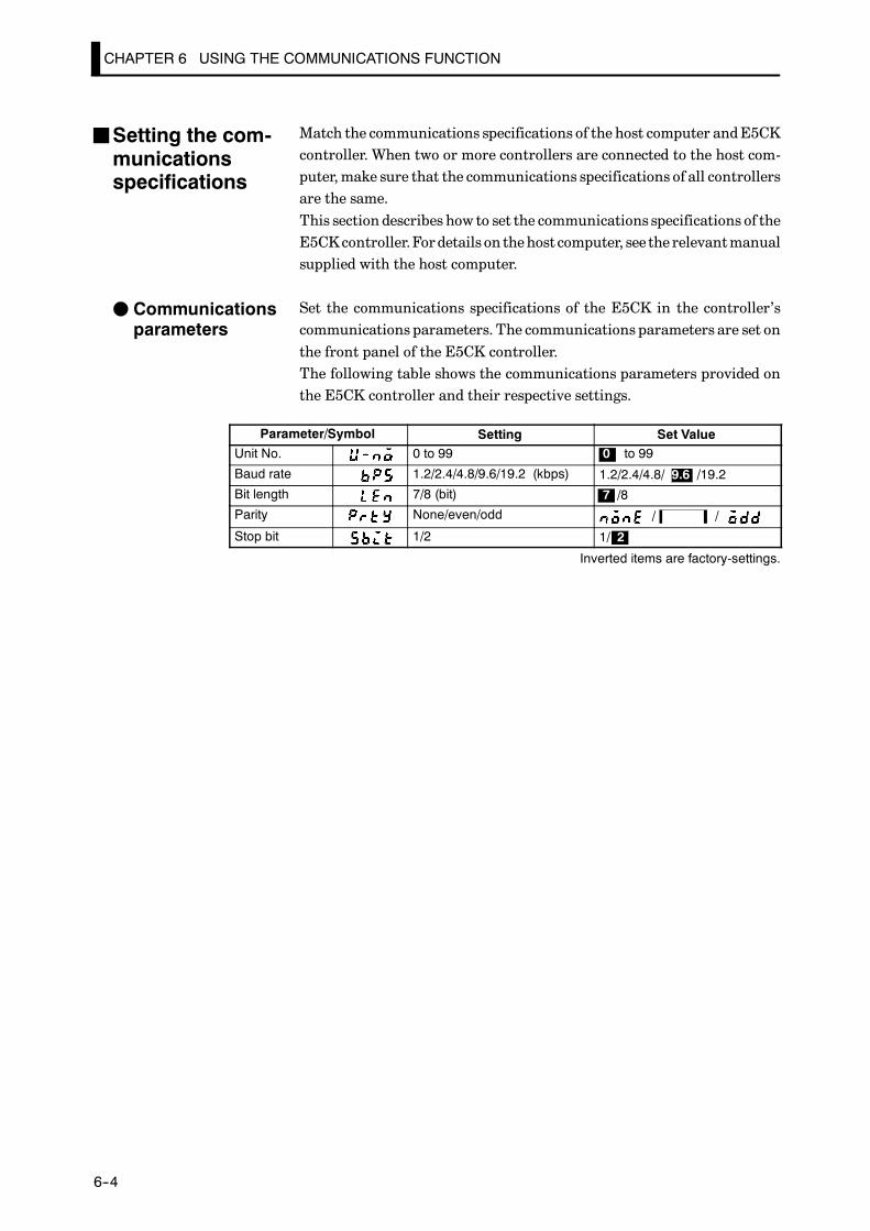
CHAPTER 6 USING THE COMMUNICATIONS FUNCTION
E5CK
6--4
Match the communications specifications of the host computer andE5CKcontroller. When two or more controllers are connected to the host com-puter,make sure that the communications specifications of all controllersare the same.This section describes how to set the communications specifications of theE5CKcontroller.Fordetails on thehost computer, see the relevantmanualsupplied with the host computer.
Set the communications specifications of the E5CK in the controller’scommunications parameters. The communications parameters are set onthe front panel of the E5CK controller.The following table shows the communications parameters provided onthe E5CK controller and their respective settings.
Parameter/Symbol Setting Set ValueUnit No. 0 to 99 0 to 99
Baud rate 1.2/2.4/4.8/9.6/19.2 (kbps) 1.2/2.4/4.8/ 9.6 /19.2
Bit length 7/8 (bit) 7 /8
Parity None/even/odd / /
Stop bit 1/2 1/ 2
Inverted items are factory-settings.
JSetting the com-municationsspecifications
F Communicationsparameters

6.3 Command Configuration
E5CK
6--5
6.3 Command Configuration
Command configuration is as follows and are paired with a response.
F Command
UnitNo.
Commandcode
Data FCS
CR
Command type
@ *
2B 1B 2B 4B 2B 2B
F Response
UnitNo.
Commandcode
Data FCS
Command type
CR
Endcode@ *
2B 1B 2B 4B 2B 2B2B
• “@”The start character. This character must be inserted before the leadingbyte.
• Unit No.Specifies the “unit No.” of the E5CK. If there are two or more transmis-sion destinations, specify the desired destination using “unit No.”
• Command typeSpecifies the command typeby codes “1” to “3”: parameter read, param-eter write and special commands.
• Command codeSpecifies the command for each command type. With parameter read/write commands, this becomes the parameter No.
• DataSpecifies the set value or setting content. In the parameter read com-mand, set dummy data “0000”. In the response, this is inserted onlywhen the end code is “00”.
• End codeSets the communication results. For details on the types and meaningsof end codes, see 6.5 How to Read Communications Error Information(page 6-10).
• FCS (Frame Check Sequence)Set the frame check results from the start character to the data section.For details on the frame check, see 6.6 Program Example (page 6-12).
• “*” “CR (Carriage Return) code”Indicates the end (terminator) of the command or response block.

CHAPTER 6 USING THE COMMUNICATIONS FUNCTION
E5CK
6--6
6.4 Commands and Responses
This section describes commands and response in detail. The conventionsused in this section and data restrictions are as follows:
• Data is expressed in 1-byte units and in ASCII code.• When the read or write data is a numerical value, the data to be setmustconform to the following conditions:(1)The decimal point “.” is not indicated in fractions.(2)The leftmost bit of minus numerical data must be expressed asfollows:[example]10.0=[0100], -150.0=[A500], -15=[F015]
JReading/writing parameters
F Reading parameters
Command
ParameterNo.
ParameterNo.
UnitNo.
FCS
CR
UnitNo.
Read data FCS
CR
Endcode
@
@
*
*
2B 2B 4B 2B 2B
2B 2B 4B 2B 2B2B
1 X X X X
1Response
X: Any value acceptable
FWriting parameters
Command
ParameterNo.
ParameterNo.
UnitNo.
Write data FCS
CR
UnitNo.
Write data FCS
CR
Endcode
@
@
*
*
2B 2B 4B 2B 2B
2B 2B 4B 2B 2B2B
2
2Response
Reading or writing of the parameters of a specified controller is executed.
• Writing is possible only during remote operation.• Reading is impossible during executing auto-tuning.• The followings are set aside as special commands. For details, see page6-9.“run/stop”, “remote/local”, “AT execute/cancel”
• For details on parameters in each setting level, see the tables on pages6-7 and 6-8.
WithX format “MA” and “ME” commands (see pageA---12), you can select non-vola-tile RAMorRAMas thememory for the set value. The limit for the number of timesthatnon-volatileRAMcan bewritten to is 100,000 times.When thenumber of timesthat the set point is written exceeds this limit, set RAMwrite mode as the memory.
Writing the SetValue
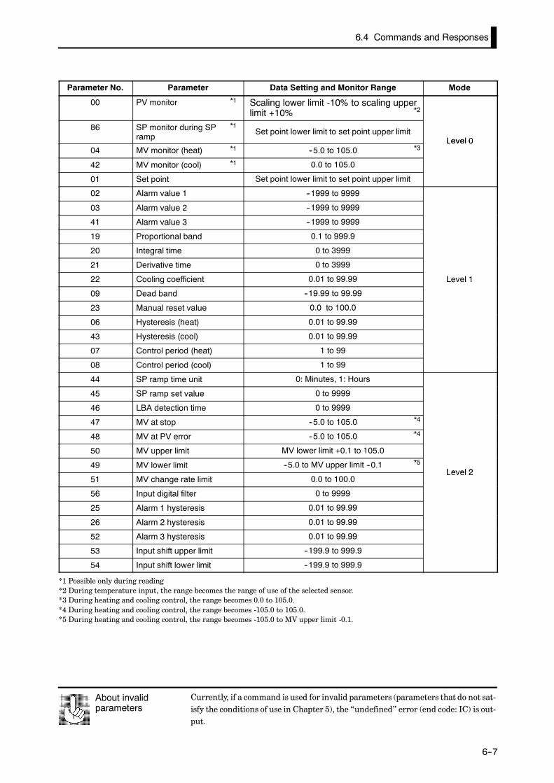
6.4 Commands and Responses
E5CK
6--7
Parameter No. Parameter Data Setting and Monitor Range Mode
00 PV monitor *1 Scaling lower limit -10% to scaling upperlimit +10%
86 SP monitor during SP *1
rampSet point lower limit to set point upper limit
Level 004 MV monitor (heat) *1 --5.0 to 105.0
Level 0
42 MV monitor (cool) *1 0.0 to 105.0
01 Set point Set point lower limit to set point upper limit
02 Alarm value 1 --1999 to 9999
03 Alarm value 2 --1999 to 9999
41 Alarm value 3 --1999 to 9999
19 Proportional band 0.1 to 999.9
20 Integral time 0 to 3999
21 Derivative time 0 to 3999
22 Cooling coefficient 0.01 to 99.99 Level 1
09 Dead band --19.99 to 99.99
23 Manual reset value 0.0 to 100.0
06 Hysteresis (heat) 0.01 to 99.99
43 Hysteresis (cool) 0.01 to 99.99
07 Control period (heat) 1 to 99
08 Control period (cool) 1 to 99
44 SP ramp time unit 0: Minutes, 1: Hours
45 SP ramp set value 0 to 9999
46 LBA detection time 0 to 9999
47 MV at stop --5.0 to 105.0
48 MV at PV error --5.0 to 105.0
50 MV upper limit MV lower limit +0.1 to 105.0
49 MV lower limit --5.0 to MV upper limit --0.1Level 2
51 MV change rate limit 0.0 to 100.0Level 2
56 Input digital filter 0 to 9999
25 Alarm 1 hysteresis 0.01 to 99.99
26 Alarm 2 hysteresis 0.01 to 99.99
52 Alarm 3 hysteresis 0.01 to 99.99
53 Input shift upper limit --199.9 to 999.9
54 Input shift lower limit --199.9 to 999.9
*1 Possible only during reading*2 During temperature input, the range becomes the range of use of the selected sensor.*3 During heating and cooling control, the range becomes 0.0 to 105.0.*4 During heating and cooling control, the range becomes -105.0 to 105.0.*5 During heating and cooling control, the range becomes -105.0 to MV upper limit -0.1.
Currently, if a command is used for invalid parameters (parameters that do not sat-isfy the conditions of use in Chapter 5), the “undefined” error (end code: IC) is out-put.
About invalidparameters
*2
*3
*4
*4
*5

CHAPTER 6 USING THE COMMUNICATIONS FUNCTION
E5CK
6--8
Parameter No. Parameter Data Setting Range Mode
57 Input type 0 to 21
59 Scaling upper limit Scaling lower limit +1 to 9999
58 Scaling lower limit --1999 to scaling upper limit --1
60 Decimal point 0 to 3
30 _C/_F selection 0 : _C, 1 : _F
61 Control output 1 assignment 0 to 4, 6
62 Control output 2 assignment 0 to 4, 6
63 Auxiliary output 1 assignment 2 to 4, 6 to 8Setup
65 Alarm 1 type 1 to 11Setup
66 Alarm 1 open in alarm 0: closed in alarm, 1: open in alarm
67 Alarm 2 type 1 to 11
68 Alarm 2 open in alarm 0: closed in alarm, 1: open in alarm
69 Alarm 3 type 1 to 11
70 Alarm 3 open in alarm 0: closed in alarm, 1: open in alarm
71 Direct/Reverse operation 0: Reverse operation, 1: Direct operation
28 Set point upper limit *5 Set point lower limit +1 to scaling upper limit
27 Set point lower limit *5 Scaling lower limit to Set point upper limit --1
72 PID / ON/OFF 0: Advanced PID, 1: ON/OFF
73 ST 0 : OFF, 1 : ON
34 ST stable range width 0.1 to 999.9
35 α 0.00 to 1.00Expansion
85 AT calculated gain 0.1 to 10.0Expansion
37 Standby sequence reset method 0, 1
36 Automatic return of display mode 0 to 99
93 AT hysteresis 0.1 to 9.9
55 LBA detection width 0.0 to 999.9
*1 See page 5-22.*2 0: Control output (heat), 1: Control output (cool), 2: Alarm 1, 3: Alarm 2, 4: Alarm 3, 6: LBA.*3 2: Alarm 1, 3: Alarm 2, 4: Alarm 3, 6: LBA, 7: Error 1, 8: Error 2*4 See page 5-25.*5 During temperature input, the range becomes the range of use of the selected sensor.*6 See page 5-30.
To read the E5CK controller status, use the X format “RX” command. For details,see the Appendix: X Format Head List (page A-13).
Reading the status
*1
*2
*2
*3
*4
*4
*4
*6

6.4 Commands and Responses
E5CK
6--9
J Issuing special commands
Commandcode
Commandcode
UnitNo.
Instruction code FCS
CR
UnitNo.
Instruction code FCS
CR
Endcode
@
@
*
*
2B 2B 4B 2B 2B
2B 2B 4B 2B 2B2B
3
3
Command
Response
The following functions are issued as special commands.
• Run/StopRunsor stopsprograms. This command cannot be issued in setting level1. Run/Stop can be switched up to 100,000 times.
• Remote/LocalSelects remote operation or local operation.
• AT Execute/CancelExecutes or cancels auto-tuning. This command cannot be issued in set-ting level 1.
• Move to setting level 1Issue this command when writing parameters in setup and expansionmodes.
• Software resetA response is not returned to this command.Also, communicationswiththe E5CK cannot be carried out for five seconds after reset.
The following table shows the special commands that are available onthe E5CK controller.
Command No. Command Instruction Code
00 Run/Stop 0000: Run, 0001: Stop02 Remote/Local 0000: Remote, 0001: Local
07 AT Execute/Cancel 0000: Cancel, 0001: 40%AT execu-tion, 0002: 100% AT execution
09 Move to setting level 1 000011 Software reset 0000
To return to setting level 0 from setting level 1, issue the “software reset” command.If the parameterwrite command is issued for the setup and expansionmodes in set-ting level 0, an error occurs, and the end code (0D= Command cannot be executed)is returned.
About Setting Levels
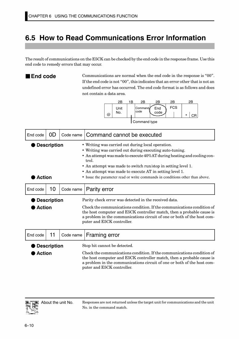
CHAPTER 6 USING THE COMMUNICATIONS FUNCTION
E5CK
6--10
6.5 How to Read Communications Error Information
The result of communications on theE5CK can be checked by the end code in the response frame.Use thisend code to remedy errors that may occur.
Communications are normal when the end code in the response is “00”.If the end code is not “00”, this indicates that an error other that is not anundefined error has occurred. The end code format is as follows and doesnot contain a data area.
CR
UnitNo.
Commandcode
FCS
Command type
Endcode@ *
2B2B 1B 2B 2B2B
End code 0D Code name Command cannot be executed
• Writing was carried out during local operation.• Writing was carried out during executing auto-tuning.• Anattemptwasmade to execute 40%ATduringheatingand cooling con-trol.
• An attempt was made to switch run/stop in setting level 1.• An attempt was made to execute AT in setting level 1.• Issue the parameter read or write commands in conditions other than above.
End code 10 Code name Parity error
Parity check error was detected in the received data.
Check the communications condition. If the communications condition ofthe host computer and E5CK controller match, then a probable cause isa problem in the communications circuit of one or both of the host com-puter and E5CK controller.
End code 11 Code name Framing error
Stop bit cannot be detected.
Check the communications condition. If the communications condition ofthe host computer and E5CK controller match, then a probable cause isa problem in the communications circuit of one or both of the host com-puter and E5CK controller.
Responses are not returned unless the target unit for communications and the unitNo. in the command match.
About the unit No.
JEnd code
F Description
F Action
F Description
F Action
F Description
F Action
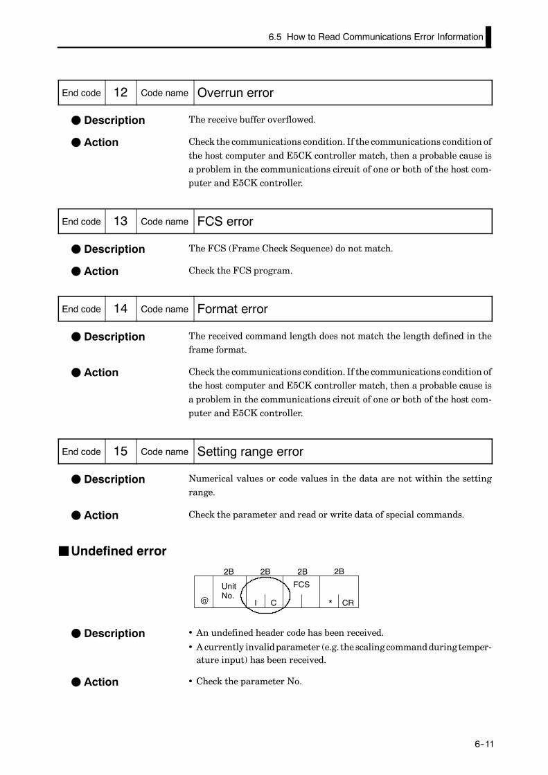
6.5 How to Read Communications Error Information
E5CK
6--11
End code 12 Code name Overrun error
The receive buffer overflowed.
Check the communications condition. If the communications condition ofthe host computer and E5CK controller match, then a probable cause isa problem in the communications circuit of one or both of the host com-puter and E5CK controller.
End code 13 Code name FCS error
The FCS (Frame Check Sequence) do not match.
Check the FCS program.
End code 14 Code name Format error
The received command length does not match the length defined in theframe format.
Check the communications condition. If the communications condition ofthe host computer and E5CK controller match, then a probable cause isa problem in the communications circuit of one or both of the host com-puter and E5CK controller.
End code 15 Code name Setting range error
Numerical values or code values in the data are not within the settingrange.
Check the parameter and read or write data of special commands.
JUndefined error
CR
UnitNo.
FCS
@ *
2B2B 2B 2B
CI
• An undefined header code has been received.
• Acurrently invalidparameter (e.g. the scaling commandduring temper-ature input) has been received.
• Check the parameter No.
F Description
F Action
F Description
F Action
F Description
F Action
F Description
F Action
F Description
F Action

CHAPTER 6 USING THE COMMUNICATIONS FUNCTION
E5CK
6--12
6.6 Program Example
JHow to use programsTheprogramdescribedbelow is for obtainingcorresponding response framedatawhensome of the command frame data is input.The input format is as follows. The FCS and terminator are automatically generated,and need not be input.
CR
UnitNo.
Commandcode
Data FCS
Command type
@ *
2B2B 1B 2B 4B 2B
Input data Automaticallygenerated
The output format is as follows. The content of the response frame is displayed as it is.
UnitNo.
Commandcode
Data FCS
Command type
CR
Endcode@ *
2B 1B 2B 4B 2B 2B2B
F Procedure(1) Read the program.
(2) Enter “RUN”.
(3) When “send data:” is displayed, enter the command data (from@to the commandstring).
(4) The content of the response frame is displayed following “receive data:”.
F Conditions when running a program• Set the communications condition as follows:
Baud rate : 9600 bpsBit length : 7 bitsParity : EvenStop bit : 2
• Make sure that the communications cable is properly connected.
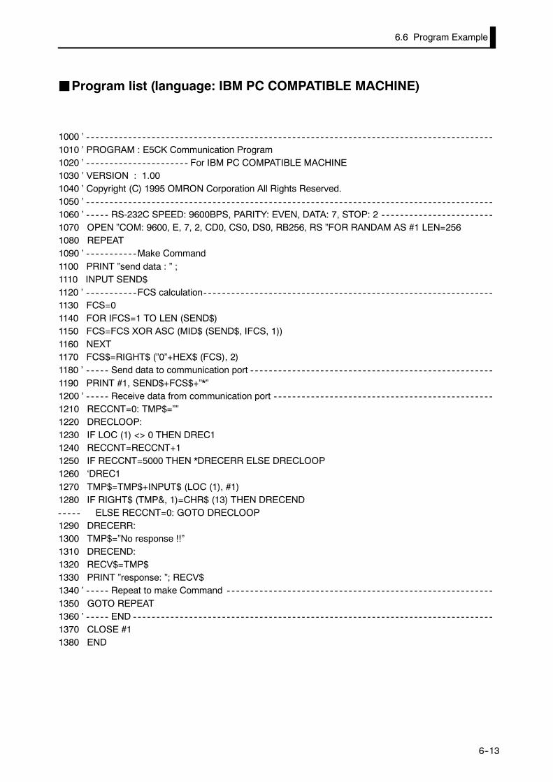
6.6 Program Example
E5CK
6--13
JProgram list (language: IBM PC COMPATIBLE MACHINE)
1000 ’1010 ’ PROGRAM : E5CK Communication Program1020 ’ For IBM PC COMPATIBLE MACHINE1030 ’ VERSION : 1.001040 ’ Copyright (C) 1995 OMRON Corporation All Rights Reserved.1050 ’1060 ’ RS-232C SPEED: 9600BPS, PARITY: EVEN, DATA: 7, STOP: 21070 OPEN ”COM: 9600, E, 7, 2, CD0, CS0, DS0, RB256, RS ”FOR RANDAM AS #1 LEN=2561080 REPEAT1090 ’ Make Command1100 PRINT ”send data : ” ;1110 INPUT SEND$1120 ’ FCS calculation1130 FCS=01140 FOR IFCS=1 TO LEN (SEND$)1150 FCS=FCS XOR ASC (MID$ (SEND$, IFCS, 1))1160 NEXT1170 FCS$=RIGHT$ (”0”+HEX$ (FCS), 2)1180 ’ Send data to communication port1190 PRINT #1, SEND$+FCS$+”*”1200 ’ Receive data from communication port1210 RECCNT=0: TMP$=””1220 DRECLOOP:1230 IF LOC (1) <> 0 THEN DREC11240 RECCNT=RECCNT+11250 IF RECCNT=5000 THEN *DRECERR ELSE DRECLOOP1260 ‘DREC11270 TMP$=TMP$+INPUT$ (LOC (1), #1)1280 IF RIGHT$ (TMP&, 1)=CHR$ (13) THEN DRECEND
ELSE RECCNT=0: GOTO DRECLOOP1290 DRECERR:1300 TMP$=”No response !!”1310 DRECEND:1320 RECV$=TMP$1330 PRINT ”response: ”; RECV$1340 ’ Repeat to make Command1350 GOTO REPEAT1360 ’ END1370 CLOSE #11380 END

CHAPTER 6 USING THE COMMUNICATIONS FUNCTION
E5CK
6--14
JExamples of use
F Set the unit No. to “00”• In the following examples, data is shown in individual blocks to make the exampleseasier to understand.However, when actually creating programs, do not leave spacesbetween frame items. Also, response are displayed without spaces between frameitems.
F Set the set point to “300.0”• Input data
@ 00 2 01 3000
300.0
Set point
Write parameter
• Response
@ 00 2 01 00 3000 (FCS) *
Normal end
F Start running• Input data
@ 00 3 00 0000
Run
Run/Stop
Special command
• Response
@ 00 3 00 00 0000 (FCS) *
Normal end
F Monitor process value• Input data
@ 00 1 00 0000
Dummy data
Monitor process value
Read parameter
• Response
@ 00 1 00 00 2000 (FCS) *
Process value = 2000
Normal end
CHAPTER 7 TROUBLESHOOTING
7--1
CHAPTER 7TROUBLESHOOTING
This chapter describeshow to findoutand remedy the cause if theE5CKdoes not function properly.
CHAPTER7
7.1 Initial Checks 7---2. . . . . . . . . . . . . . . . . . . . . . . . . .
7.2 How to Use the Error Display 7---3. . . . . . . . . . .
7.3 How to Use Error Output 7---5. . . . . . . . . . . . . . .
7.4 Checking Operation Restrictions 7---6. . . . . . . .
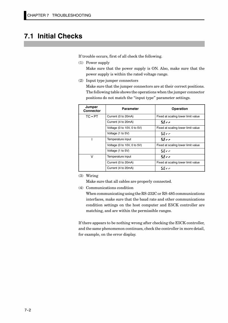
CHAPTER 7 TROUBLESHOOTING
E5CK
7--2
7.1 Initial Checks
If trouble occurs, first of all check the following.
(1) Power supplyMake sure that the power supply is ON. Also, make sure that thepower supply is within the rated voltage range.
(2) Input type jumper connectorsMake sure that the jumper connectors are at their correct positions.The following table shows the operationswhen the jumper connectorpositions do not match the “input type” parameter settings.
JumperConnector Parameter Operation
TC S PT Current (0 to 20mA) Fixed at scaling lower limit value
Current (4 to 20mA)
Voltage (0 to 10V, 0 to 5V) Fixed at scaling lower limit value
Voltage (1 to 5V)
I Temperature input
Voltage (0 to 10V, 0 to 5V) Fixed at scaling lower limit value
Voltage (1 to 5V)
V Temperature input
Current (0 to 20mA) Fixed at scaling lower limit value
Current (4 to 20mA)
(3) WiringMake sure that all cables are properly connected.
(4) Communications conditionWhen communicating using theRS-232Cor RS-485 communicationsinterfaces, make sure that the baud rate and other communicationscondition settings on the host computer and E5CK controller arematching, and are within the permissible ranges.
If there appears to be nothing wrong after checking the E5CK controller,and the same phenomenon continues, check the controller in more detail,for example, on the error display.
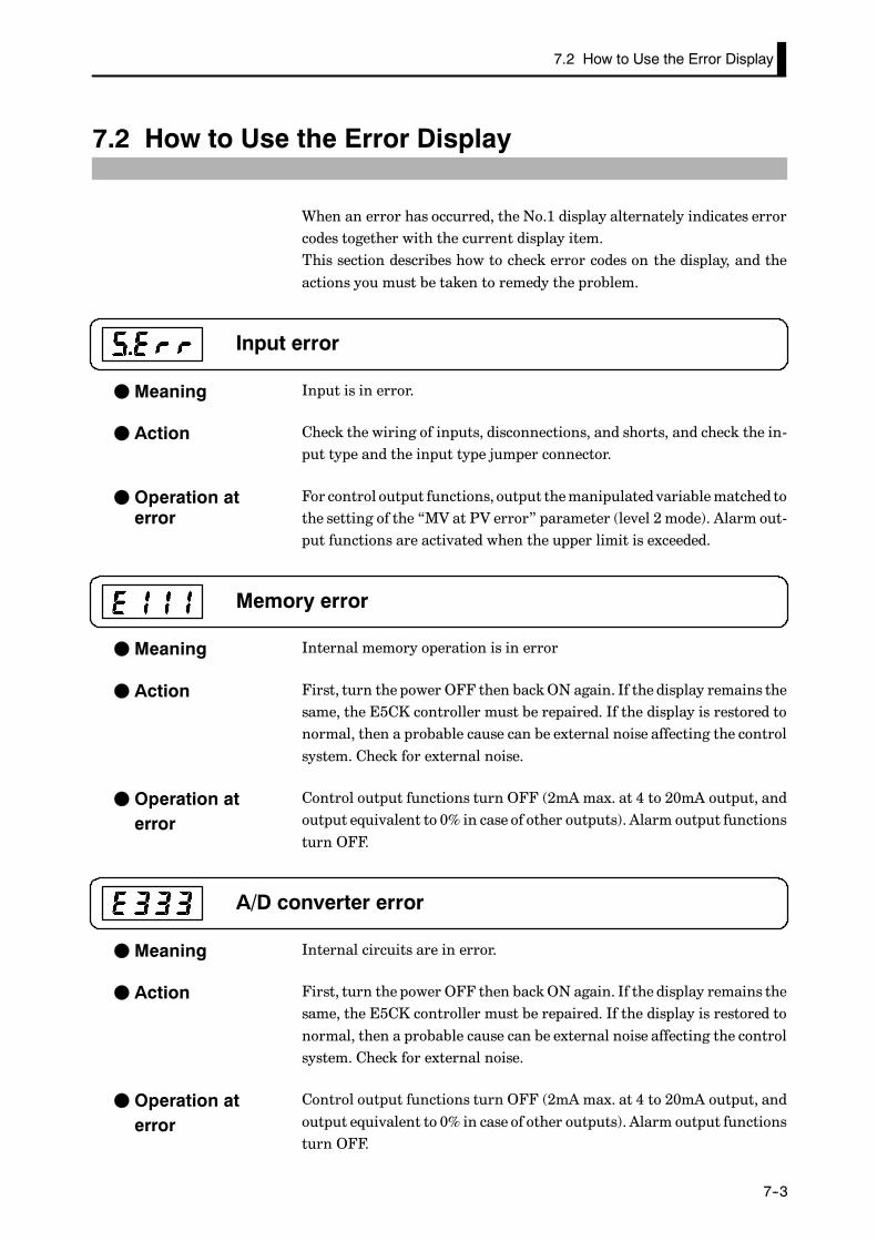
7.2 How to Use the Error Display
E5CK
7--3
7.2 How to Use the Error Display
When an error has occurred, the No.1 display alternately indicates errorcodes together with the current display item.This section describes how to check error codes on the display, and theactions you must be taken to remedy the problem.
Input error
Input is in error.
Check the wiring of inputs, disconnections, and shorts, and check the in-put type and the input type jumper connector.
For control output functions, output themanipulated variablematched tothe setting of the “MV at PV error” parameter (level 2 mode). Alarm out-put functions are activated when the upper limit is exceeded.
Memory error
Internal memory operation is in error
First, turn the power OFF then backON again. If the display remains thesame, the E5CK controller must be repaired. If the display is restored tonormal, then a probable cause can be external noise affecting the controlsystem. Check for external noise.
Control output functions turn OFF (2mA max. at 4 to 20mA output, andoutput equivalent to 0% in case of other outputs). Alarm output functionsturn OFF.
A/D converter error
Internal circuits are in error.
First, turn the power OFF then backON again. If the display remains thesame, the E5CK controller must be repaired. If the display is restored tonormal, then a probable cause can be external noise affecting the controlsystem. Check for external noise.
Control output functions turn OFF (2mA max. at 4 to 20mA output, andoutput equivalent to 0% in case of other outputs). Alarm output functionsturn OFF.
F Meaning
F Action
F Operation aterror
F Meaning
F Action
F Operation aterror
F Meaning
F Action
F Operation aterror

CHAPTER 7 TROUBLESHOOTING
E5CK
7--4
Calibration data error
This error is output only during temperature input, and is displayed fortwo seconds when the power is turned ON.
Calibration data is in error.
Must repair.
Both control output functions and alarm output functions operate. How-ever, note that readout accuracy is not assured.
Display range over
Though not an error, this is displayed when the process value exceeds thedisplay range when the control range (setting range ±10%) is larger thanthe display range (---1999 to 9999).
• When less than “-1999” [ ]
• When greater than “9999” [ ]
Control continues, allowing normal operation.
F Meaning
F Action
F Operation aterror
F Meaning
F Operation
7.3 How to Use Error Output
E5CK
7--5
7.3 How to Use Error Output
TheE5CKcontroller allowsyou toassign error output to terminals asout-puts.For details on output assignments, see 3.3 Setting Output Specifications(page 3-5).
• LBA (Loop Break Alarm) can be used as a means for detecting loopbreakswhen thecontrol loop is not functioningnormally.For details, seepage 4-9.
• LBA allows you to detect the following errors:
(1) Heater burnout(2) Output error (contact weld, damaged transistors, etc.)(3) Sensor error (constant input values, etc.)
• If you use the LBA function, set the loop break detection time matchedto the control characteristics in the “LBA detection time” parameter(level 2 mode).
• If you assign error 1 as the output, an error can be output when inputis in error. When this error occurs, remedy by following the descriptionfor “Input error” (page 7-3).
• If you assign error 2 as the output, an error can be outputwhen theA/Dconverter is in error. When this error occurs, remedy by following thedescription for “A/D converter error” (page 7-3).
F LBA
F Input errors
F A/D convertererror

CHAPTER 7 TROUBLESHOOTING
E5CK
7--6
7.4 Checking Operation Restrictions
With the E5CK controller, auto-tuning or self-tuning sometimes do notoperate depending on the way functions are combined. The table belowsummarizes the main operating restrictions.If theE5CK controller is not operating properly, first checkwhether oper-ating conditions violate the restrictions in this table.
RestrictionInoperable or Invalid Functions
RestrictionST Execution AT Execution Limiter Function Other
At analog input ¢
At heating andcooling control
¢ 40%AT
At ON/OFFcontrol
¢ ¢ Manipulated variableMV change rate
ST = ON -- ¢ Manipulated variableMV change rate
SP ramp function
At AT execution -- -- MV change rate Parameter setting
At stop ¢ ¢ Manipulated variableMV change rate
Itemsmarked by a “x” indicates combinations of conditions not acceptable during ST or AT execution.
Items marked by “---” are impossible combinations.
APPENDIX
A--1
APPENDIX
SPECIFICATIONS A---2. . . . . . . . . . . . . . . . . . . . . . . . .
CONTROL BLOCK DIAGRAM A---5. . . . . . . . . . . . . .
SETTING LIST A---6. . . . . . . . . . . . . . . . . . . . . . . . . . . .
PARAMETER OPERATIONS LIST A---8. . . . . . . . . .
FUZZY SELF-TUNING A---10. . . . . . . . . . . . . . . . . . . . .
MODEL LIST A---13. . . . . . . . . . . . . . . . . . . . . . . . . . . . . .
X FORMAT A---14. . . . . . . . . . . . . . . . . . . . . . . . . . . . . . . .
ASCII CODE LIST A---17. . . . . . . . . . . . . . . . . . . . . . . . . .

APPENDIX
E5CK
A--2
SPECIFICATIONS
JRatings
AC100--240V type AC/DC24V type
Supply Voltage AC100--240V , 50/60 Hz~ AC/DC24 , 50/60Hz
Power Consumption 15VA 6VA, 3.5W
Operating VoltageRange 85% to 110% of rated supply voltage
Input
Thermocouple : K, J, T, E, L, U, N, R, S, B, W, PLIIPlatinum resistance thermometer : JPt100, Pt100Current input : 4 to 20mA, 0 to 20mAVoltage input : 1 to 5V, 0 to 5V, 1 to 10V
Input Impedance Voltage input : 1 MΩ min.Current input : 150 Ω
Control Output According to output unit (see “Output Unit Ratings and Characteristics”)
Auxiliary Output SPST-NO, 1A at 250 VAC (resistive load)
Control Method Advanced PID or ON/OFF control
Setting Method Digital setting using front panel keys
Indication Method 7-segment digital display and LEDs
Other Functions According to option unit (see “Option Unit Ratings and Characteristics”)
Ambient Temperature Operating : -10°C to 55°C (with no icing)/3-year warranty period: -10°C to 50°CStorage : -25°C to 65°C (with no icing)
Ambient Humidity 35% to 85% RH
*1 Thermocouple W is W/Re5-26 (tungsten rhenium 5, tungsten rhenium 26).*2 The following table shows the setting ranges and indication ranges for each of the inputs.
Input Setting Range Indication Range
JPt100 --199.9 to 650.0(_C) /--199.9 to 999.9(_F) --199.9 to 735.0(_C) /--199.9 to 999.9(_F)
Pt100 --199.9 to 650.0(_C) /--199.9 to 999.9(_F) --199.9 to 735.0(_C) /--199.9 to 999.9(_F)
K1 --200 to 1300(_C) /--300 to 2300(_F) --350 to 1450(_C) /--560 to 2560(_F)
K2 0.0 to 500.0(_C) /0.0 to 900.0(_F) --50.0 to 550.0(_C) /--90.0 to 990.0(_F)
J1 --100 to 850(_C) /--100 to 1500(_F) --195 to 945(_C) /--260 to 1660(_F)
J2 0.0 to 400.0(_C) /0.0 to 750.0(_F) --40.0 to 440.0(_C) /--75.0 to 825.0(_F)
T --199.9 to 400.0(_C) /--199.9 to 700.0(_F) --199.9 to 460.0(_C) /--199.9 to 790.0(_F)
E 0 to 600(_C) /0 to 1100(_F) --60 to 660(_C) /--110 to 1210(_F)
L1 --100 to 850(_C) /--100 to 1500(_F) --195 to 945(_C) /--260 to 1660(_F)
L2 0.0 to 400.0(_C) /0.0 to 750.0(_F) --40.0 to 440.0(_C) /--75.0 to 825.0(_F)
U --199.9 to 400.0(_C) /--199.9 to 700.0(_F) --199.9 to 460.0(_C) /--199.9 to 790.0(_F)
N --200 to 1300(_C) /--300 to 2300(_F) --350 to 1450(_C) /--560 to 2560(_F)
R 0 to 1700(_C) /0 to 3000(_F) --170 to 1870(_C) /--300 to 3300(_F)
S 0 to 1700(_C) /0 to 3000(_F) --170 to 1870(_C) /--300 to 3300(_F)
B 100 to 1800(_C) /300 to 3200(_F) --70 to 1970(_C) /10 to 3490(_F)
W 0 to 2300(_C) /0 to 4100(_F) --230 to 2530(_C) /--410 to 4510(_F)
PLII 0 to 1300(_C) /0 to 2300(_F) --130 to 1430(_C) /--230 to 2530(_F)
4 to 20mA0 to 20mA1 to 5V0 to 5V0 to 10V
One of following ranges depending on results ofscaling--1999 to 9999--199.9 to 999.9--19.99 to 99.99--1.999 to 9.999
-10 to 110% of setting range. Note, however thatmax. value is -1999 to 9999
*1, *2

SPECIFICATIONS
E5CK
A--3
JCharacteristics
Indication Accuracy
Thermocouple:
(±0.3% of indication value or ± 1°C, whichever greater) ± 1 digit max. (*1)
Platinum resistance thermometer:
(±0.2% of indication value or ± 0.8°C whichever greater)± 1 digit max.
Analog input: ±0.2%± 1 digit max.
Temperature variation influ-ence (*2)
Platinum resistance thermometer:(±1% of PV or ± 2°C, whichever greater) ±1 digit max.Thermocouple (R, S, B, W):(±1% of PV or ± 10°C whichever greater) ±1 digit max
Voltage variation influence(*2)
(±1% of PV or ± 10°C, whichever greater) ±1 digit max.Other thermocouples (K1, K2, J1, J2, E, N, T, L1, L2, U, PLII):(±1% of PV or ± 4°C, whichever greater) ±1 digit max.Analog input (current, voltage, or remote SP input): ±1%FS±1 digit max.
Hysteresis 0.01 to 99.99%FS (in units of 0.01%FS)
Proportional Band (P) 0.1 to 999.9% FS (in units of 0.1%FS)
Integral (reset) Time (I) 0 to 3999 s (in units of 1 second)
Derivative (rate) Time (D) 0 to 3999 s (in units of 1 second)
Control Period 1 to 99 s (in units of 1 second)
Manual Reset Value 0.0 to 100.0% (in units of 0.1%)
Alarm Setting Range -1999 to 9999 or -199.9 to 999.9 (decimal point position dependent on inputtype)
Sampling Period Temperature input: 250 ms, Analog input: 100 ms
Insulation Resistance 20 MΩ min. (at 500 VDC)
Dielectric Strength 2000 VAC, 50/60Hz for 1 min (between terminals of different polarities)
Vibration Malfunction 10 to 55 Hz, 10 m/s2 (1G) for 10 min each in X, Y, and Z directionsVibrationResistance Destruction 10 to 55 Hz, 20 m/s2 (2G) for 2hrs each in X, Y, and Z directions
Shock Resis-tance
Malfunction 200 m/s2 min. (20G), 3 times each in 6 directions (100 m/s2 (10G) applied to therelay)
tanceDestruction 300 m/s2 min. (30G), 3 times each in 6 directions
Weight Approx. 170 g, adapter: approx. 10 g
Enclosure RatingsFront panel: NEMA4 for indoor use (equivalent to IP66)Rear case: IEC standard IP20Terminals: IEC standard IP00
Memory Protection Non-volatile memory (Write operation : 100000 max.) (*3)
*1The indication accuracy of the K1, T, andN thermocouples at a temperature of -100°C or less is ±2°C±1 digit maximum. Theindication accuracy of the U, L1 and L2 thermocouples at any temperature is ±2°C ±1 digit maximum.The indication accuracy of the B thermocouple at a temperature of 400°C or less is unrestricted.The indication accuracy of the R and S thermocouples at a temperature of 200°C or less is ±3°C ±1 digit maximum.The indication accuracy of theW thermocouple is ±1 digit max. of whichever is the greater of ±0.3% or ±3°C of the indicatedvalue.The indicationaccuracy of the PLII thermocouple is±1 digitmax. ofwhichever is the greater of±0.3%or±2°Cof the indicatedvalue.
*2 Ambient temperature: ---10°C to 23°C to 55°CVoltage range: ---15 to +10% of rated voltage
*3 Write operations: Parameter changes, remote/local selection, etc.

APPENDIX
E5CK
A--4
JOutput Unit Ratings and Characteristics
Relay output
SPST, 250 VAC, 3A (resistive load)
Mechanical life expectancy: 10,000,000 operations min
Electrical life expectancy: 100,000 operations min
Voltage Output (NPN) NPN, 12 VDC, 20 mA (with short-circuit protection)
Voltage Output (PNP) PNP, 12 VDC, 20 mA (with short-circuit protection)
Linear Voltage Output 0 to 10 VDC, Permissible load impedance: 1 kΩ min., Resolution:Approx. 2600
Linear Current Output
4 to 20 mA, Permissible load impedance: 500 Ω max., Resolution:Approx. 2600
Linear Current Output0 to 20 mA, Permissible load impedance: 500 Ω max., Resolution:Approx. 2600
JOption Unit Ratings and Characteristics
Contact input ON: 1 kΩ max., OFF: 100 kΩ min.
Event inputsNo-contact input ON: residual voltage 1.5 V max., OFF: leakage current 0.1 mA
max.
Communications
Interface :RS-232C or RS-485
Transmission method :Half-duplex
Synchronization method :Start-stop synchronization (asynchronous method)
Baud rate :1.2/2.4/4.8/9.6/19.2 kbps
Transfer output 4 to 20 mA, Permissible load impedance: 500 Ω max. Resolution: Approx. 2600

CONTROL BLOCK DIAGRAM
E5CK
A--5
CONTROL BLOCK DIAGRAM
Temperatureinput
Digital filter
Input shift
Analog input
Digital filter
Scaling
Input type
Control method
Control mode
ON/OFFcontrol PID control ON/OFF control
3-position control PID control
Control mode
Process/function
Control
Data
MV changerate limiter
MV limiter
Heatingside
Coolingside MV change
rate limiter
MV limiter
Dead band
Error
Stop
Manual
MV at PVerror
MV at stop
Manual MV
Error
Stop
Manual
Manipulated vari-able at heating side
Manipulated vari-able at coolingside
Set pointlimiter
Processvalue
Set point SP ramp
Heating andCooling control
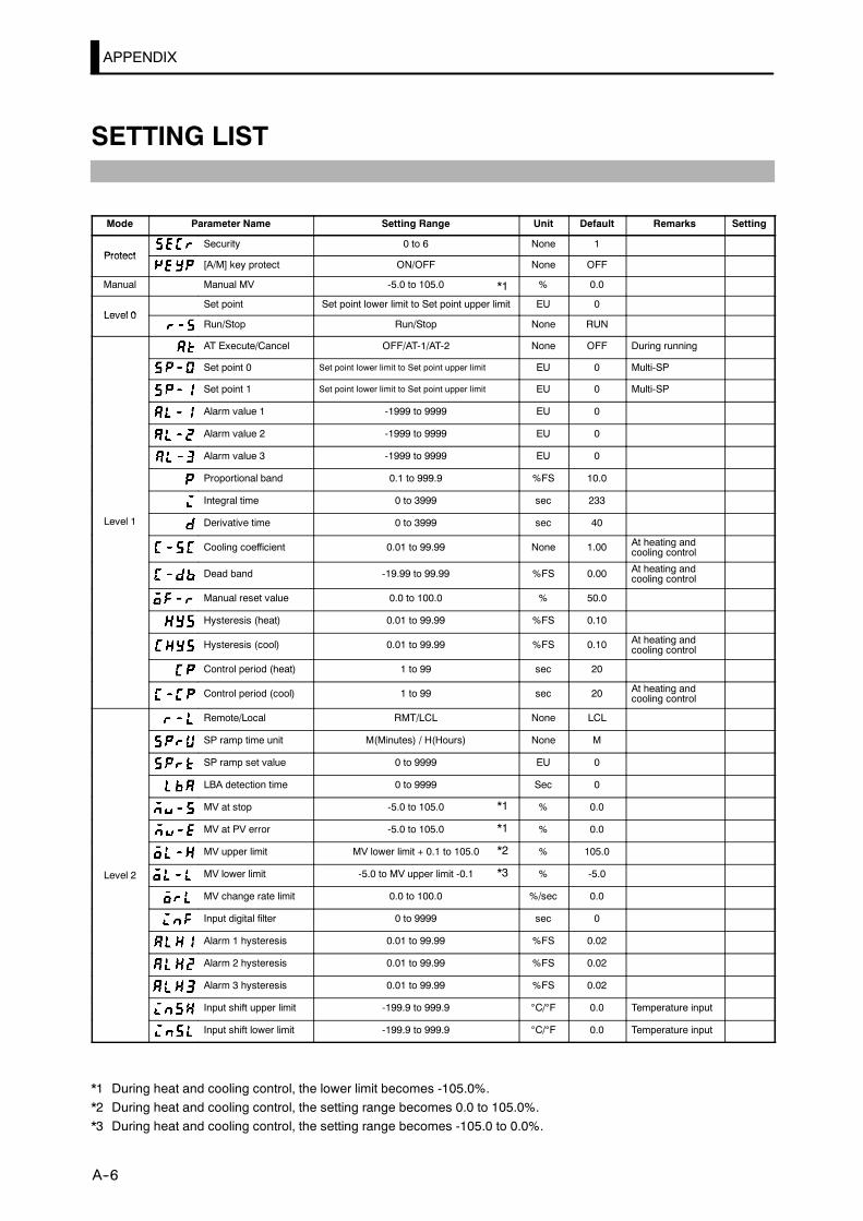
APPENDIX
E5CK
A--6
SETTING LIST
Mode Parameter Name Setting Range Unit Default Remarks Setting
ProtectSecurity 0 to 6 None 1
Protect[A/M] key protect ON/OFF None OFF
Manual Manual MV -5.0 to 105.0 % 0.0
Level 0Set point Set point lower limit to Set point upper limit EU 0
Level 0Run/Stop Run/Stop None RUN
AT Execute/Cancel OFF/AT-1/AT-2 None OFF During running
Set point 0 Set point lower limit to Set point upper limit EU 0 Multi-SP
Set point 1 Set point lower limit to Set point upper limit EU 0 Multi-SP
Alarm value 1 -1999 to 9999 EU 0
Alarm value 2 -1999 to 9999 EU 0
Alarm value 3 -1999 to 9999 EU 0
Proportional band 0.1 to 999.9 %FS 10.0
Integral time 0 to 3999 sec 233
Level 1 Derivative time 0 to 3999 sec 40
Cooling coefficient 0.01 to 99.99 None 1.00 At heating andcooling control
Dead band -19.99 to 99.99 %FS 0.00 At heating andcooling control
Manual reset value 0.0 to 100.0 % 50.0
Hysteresis (heat) 0.01 to 99.99 %FS 0.10
Hysteresis (cool) 0.01 to 99.99 %FS 0.10 At heating andcooling control
Control period (heat) 1 to 99 sec 20
Control period (cool) 1 to 99 sec 20 At heating andcooling control
Remote/Local RMT/LCL None LCL
SP ramp time unit M(Minutes) / H(Hours) None M
SP ramp set value 0 to 9999 EU 0
LBA detection time 0 to 9999 Sec 0
MV at stop -5.0 to 105.0 % 0.0
MV at PV error -5.0 to 105.0 % 0.0
MV upper limit MV lower limit + 0.1 to 105.0 % 105.0
Level 2 MV lower limit -5.0 to MV upper limit -0.1 % -5.0
MV change rate limit 0.0 to 100.0 %/sec 0.0
Input digital filter 0 to 9999 sec 0
Alarm 1 hysteresis 0.01 to 99.99 %FS 0.02
Alarm 2 hysteresis 0.01 to 99.99 %FS 0.02
Alarm 3 hysteresis 0.01 to 99.99 %FS 0.02
Input shift upper limit -199.9 to 999.9 °C/°F 0.0 Temperature input
Input shift lower limit -199.9 to 999.9 °C/°F 0.0 Temperature input
*1 During heat and cooling control, the lower limit becomes -105.0%.*2 During heat and cooling control, the setting range becomes 0.0 to 105.0%.*3 During heat and cooling control, the setting range becomes -105.0 to 0.0%.
*1
*1
*1
*2
*3

SETTING LIST
E5CK
A--7
Mode Parameter Name Setting Range Unit Default Remarks Setting
Input type 0 to 21 None 2
Scaling upper limit Scaling lower limit +1 to 9999 EU -100 Analog input
Scaling lower limit -1999 to SP setting upper limit -0.1 EU 0 Analog input
Decimal point 0 to 3 None 0 Analog input
_C/_F selection _C/_F None _C Temperature input
Parameter initialize Yes/No None NO
Control output 1 assignment Heat/Cool/Alarm 1/Alarm 2/Alarm3/LBA None HEAT
Control output 2 assignment Heat/Cool/Alarm 1/Alarm 2/Alarm3/LBA None AL-1
SetupAuxiliary output 1 assignment Alarm 1/Alarm 2/Alarm 3/LBA/
S.ERR/E333 None AL-2Setup
Alarm 1 type 1 to 11 None 2 Output assignmentneeded
Alarm 1 open in alarm N-O/N-C None N-O Output assignmentneeded
Alarm 2 type 1 to 11 None 2 Output assignmentneeded
Alarm 2 open in alarm N-O/N-C None N-O Output assignmentneeded
Alarm 3 type 1 to 11 None 2 Output assignmentneeded
Alarm 3 open in alarm N-O/N-C None N-O Output assignmentneeded
Direct/Reverse operation OR-D/OR-R None OR-R
Set point upper limit Set point lower limit +1 to scalingupper limit None 1300
Set point lower limit Scaling lower limit to Set point upperlimit -1 None -200
PID/ON/OFF PID / ON/OFF None PID
ST OFF/ON None OFF
EST stable range 0.1 to 999.9 °C/°F 15.0 ST=ON
Expan-sion
α 0.00 to 1.00 None 0.65sion
AT calculated gain 0.1 to 10.0 None 1.0
Standby sequence reset set-ting method 0/1 None 0
Automatic return of displaymode 0 to 99 Sec 0
AT hysteresis 0.1 to 9.9 %FS 0.2
LBA detection width 0.0 to 999.9 %FS 0.2
Multi-SP function 0/1 None 0
Event input assignment 1 STOP/MAN None STOP
Communication stop bit 1/2 bits 2
Communication data length 7/8 bits 7
OptionCommunication parity None/Even/Odd None EVEN
OptionCommunication baud rate 1.2/2.4/4.8/9.6/19.2 kbps 9.6
Communication unit No. 0 to 99 None 0
Transfer output type SP/SP-M/PV/O/C-O None SP
Transfer output upper limit *5 *5 *5
Transfer output lower limit *5 *5 *5
*4 When temperature input is selected, the sensor range selected in the “input type” parameter (setupmode) correspondsto the scaling upper and lower limit value.
*5 Set the transfer output type parameter according to the following table.
Transfer Output Type Transfer Output Lower Limit to Transfer Output Upper Limit
SP :Set point Set point lower limit to Set point upper limit
SP-M :Set point during SP ramp Set point lower limit to Set point upper limit
PV :Process value Scaling lower limit to scaling upper limit
O :Manipulated variable (heat) -5.0 to 105.0%
C-O :Manipulated variable (cool) 0.0 to 105.0%
D The output ranges of the SP setting, set point or process value when temperature input is selected are the ranges supportedby the selected sensor.
D When the heating side manipulated variable or cooling side manipulated variable is selected, the transfer output lower limit ina heating and cooling control becomes “0.0”.
*4*4
*4*2
*2*4

APPENDIX
E5CK
A--8
PARAMETER OPERATIONS LIST
• Switching tomodes other thanmanual or protectmode is carried out bymode selection in themenudisplay.
• The figure below shows all parameters in the order that they are displayed. Some parameters arenot displayed depending on the protect mode setting and conditions of use.
A/M
A/M
A/MA/M
A/M
+ +
+
1 second min.
Level 0 mode
Level 1 mode
Level 2 mode
Setup mode
Expansionmode
Option mode
Calibrationmode
1 second min.
Manual mode
Protect mode
1 second min.
1 second min. 1 second min.
1 second min.
Parameters in a mode can beswitched by the key. The param-eter following the last parameter is thetop parameter.
Level 0
PV/SP
Set point during SP ramp
MV monitor (heat)
MV monitor (cool)
Run/Stop
Manual MV
Security
[A/M] key protect
Manual mode
Protect mode
AT Execute/Cancel
Set point 0
Set point 1
Alarm value 1
Alarm value 2
Alarm value 3
Proportional band
Integral time
Derivative time
Cooling coefficient
Dead band
Manual reset value
Hysteresis (heat)
Hysteresis (cool)
Control period (heat)
Control period (cool)
Level 1
Remote/Local
SP ramp time unit
SP ramp set value
LBA detection time
MV at stop
MV at PV error
MV upper limit
MV lower limit
MV change rate limit
Input digital filter
Alarm 1 hysteresis
Alarm 2 hysteresis
Alarm 3 hysteresis
Input shift upper limit
Input shift lower limit
Level 2
1 second min.
Power ON
1 second min.
1 second min.
1 second min.
1 second min.
1 second min.
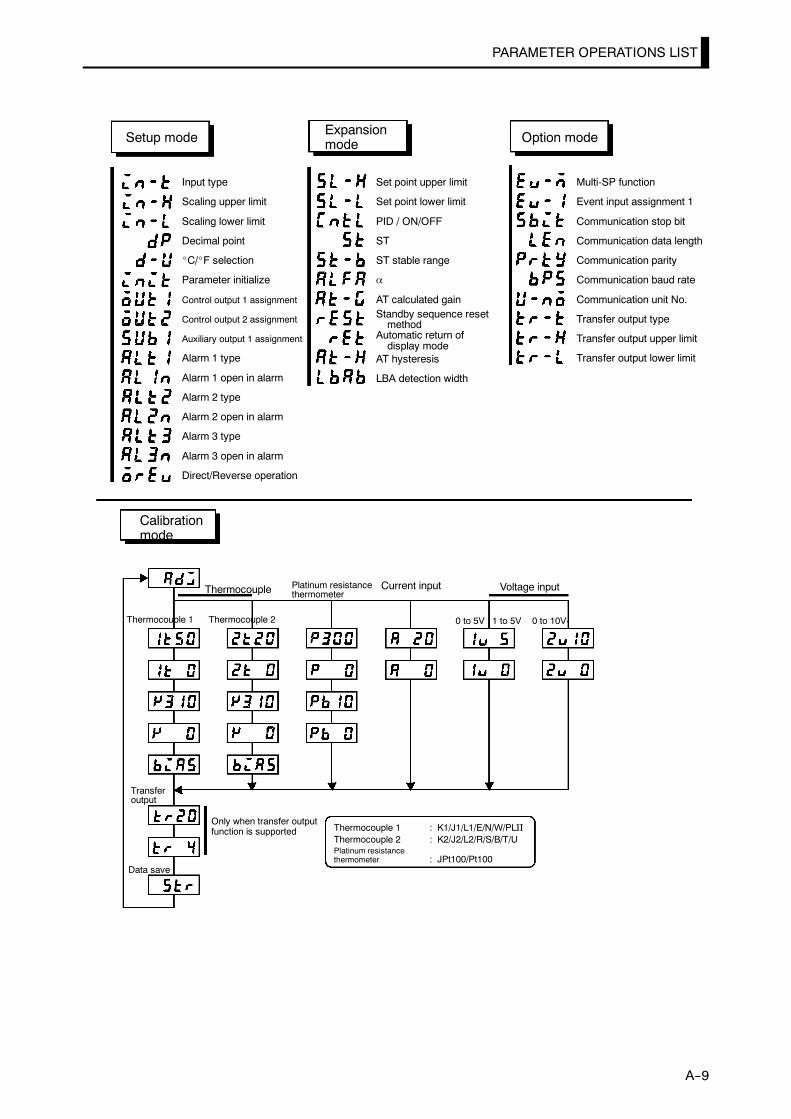
PARAMETER OPERATIONS LIST
E5CK
A--9
Input type
Scaling upper limit
Scaling lower limit
Decimal point
_C/_F selection
Parameter initialize
Control output 1 assignment
Control output 2 assignment
Auxiliary output 1 assignment
Alarm 1 type
Alarm 1 open in alarm
Alarm 2 type
Alarm 2 open in alarm
Alarm 3 type
Alarm 3 open in alarm
Direct/Reverse operation
Setup mode
Set point upper limit
Set point lower limit
PID / ON/OFF
ST
ST stable range
α
AT calculated gainStandby sequence resetmethod
Automatic return ofdisplay mode
AT hysteresis
LBA detection width
Expansionmode
Multi-SP function
Event input assignment 1
Communication stop bit
Communication data length
Communication parity
Communication baud rate
Communication unit No.
Transfer output type
Transfer output upper limit
Transfer output lower limit
Option mode
Calibrationmode
Thermocouple Platinum resistancethermometer
Current input Voltage input
Thermocouple 1 Thermocouple 2
Transferoutput
Data save
0 to 5V 1 to 5V 0 to 10V
Only when transfer outputfunction is supported Thermocouple 1 : K1/J1/L1/E/N/W/PLII
Thermocouple 2 : K2/J2/L2/R/S/B/T/UPlatinum resistancethermometer : JPt100/Pt100
APPENDIX
E5CK
A--10
FUZZY SELF--TUNING
Fuzzy self-tuning is a function thatenables theE5CKto calculate themostsuitable PID constants for the controlled object.
JFeatures• The E5CK determines by itself when to perform fuzzy self-tuning.
JFuzzy Self--tuning FunctionThe fuzzy self-tuning function has three modes.
In SRT(step response tuning) mode, the PID constants are tunedusing a step response method at the time the set point is changed.In DT(disturbance tuning) mode, the PID constants are amendedso that the controlled temperature will be within the target rangeset in advance when there is external disturbance.In HT(hunting tuning) mode, when hunting occurs, the PIDconstants are amended to suppress the hunting.
Note: Be sure to turn on the power supply to the load either before or si-multaneously with the start of Temperature Controller operation.Dead time will be measured from the time the Temperature Con-troller starts operating. If a load such as a heater is turned on aftertheTemperature Controller is turned on, dead time longer than theactual valuewill bemeasuredand inappropriatePID constantswillbe obtained. If an extremely large amount of dead time ismeasured,the control amountwill be set to 0% for a short period of timebeforebeing returned to 100%, and the constants will then be returned.Retuning is performed only for large amounts of dead time, so besure to follow the precaution given above when starting operation.
SRT will start if the following conditions are satisfied simultaneouslywhen the E5CK is turned on or the set point is changed.
At the time the E5CK starts operation At the time set point is changed
1) The set point at the time the E5CKstarts operating is different from theset point used at the time SRT waslast executed (see note).
2) The difference between the set pointand the process value at the time theE5CK starts operating is larger thanthe present proportional band value(P) x 1.27+4
3) The process value at the time theE5CK starts operating is smallerthan the set point in reverse opera-tion and larger than the set point innormal operation.
1) The newset point is different from theset point used at the time SRT wasexecuted last (see note).
2) The set point changing range is larg-er than the present proportionalbandvalue(P) x 1.27+4.
3) The process value is in stable condi-tion before the set point is changed.
4) A larger set point value is set inreverse operation and a smaller setpoint is set in normal operation.
Note: The last SRT-executed set point is set to 0 before shipping andwhenchanging from advancedPID control to advancedPID control withfuzzy self-tuning.
F StartupConditions ofSRT

FUZZY SELF--TUNING
E5CK
A--11
In order to prevent overshooting, the step controlled amount must beimposed continuously only while the present deviation is the same as orgreater than thevalueobtained fromtheproportional band (P)x 1.27.Thestep control will not be applied when the deviation becomes smaller thanthis value.
If the step control amount is applied before the maximum temperatureslope (R) is obtained, SRTwill not renew any PID constant. If the propor-tional band obtained from the R and L values that were measured beforethe imposition hadbeen completed is larger than thepresent proportionalband, the PID constantswill be renewed because themeasured value is inthe direction towards the suitable proportional band value, and the setpoint at that time will be the SRT-executed set point.
TemperatureSlope (R)
SP
Stable range
P x 1.27
Completion of SRT
Time
F Stable Temperature StatusIf thetemperature iswithin thestable range for a certain time, it isdeemedthat thetemperature is stable.This time is calledstability judgement time.Like PID constants, stability judgement time is adjusted with fuzzy self-tuningaccording to thecharacteristicsof theobject tobe controlled.Fuzzyself-tuning will not be activated if the temperature is stable because theTemperature Controller deems that temperature control is smooth.
Stable
Stable range
Stable range
Stable
Stability judgement time
Set point
Shorter than the stability judgement time
(Set to 15.0_Cbefore shipping)
F ImpositionCompletionCondition of StepControl Amount
F PID ConstantRefreshingConditions

APPENDIX
E5CK
A--12
F Balanced StatusIf the process value is within the stable range for 60swhen there is no out-put,it is deemed that the temperature is balanced.
F Startup Conditions of DT(1) DT will start if the temperature that has been stable varies due to ex-
ternal disturbance and the deflection of the temperature exceeds thestable range, and then the temperature becomes stable, provided thatthe number of maximum temperature values is less than four.
(2) DT will start if the set point is changed under the condition that SRTdoes not start and the temperature becomes stable, provided that thenumber ofmaximumtemperature values is less than four. If there arefour or more maximum temperature values, HT will start.
Temperature
Extreme value 2
SP
Set point change
Extreme value 1
Time
F Startup Conditions of HTHTwill beONwhen there is huntingwith four ormoremaximumtemper-ature values(extreme values) while SRT is not being executed.
Temperature
Extreme value 2
SP
Extreme value 4
Extremevalue 1
Time
Extremevalue 3
Note: In specific applications where temperature varies periodically dueto disturbance, internal parameters need to be adjusted.
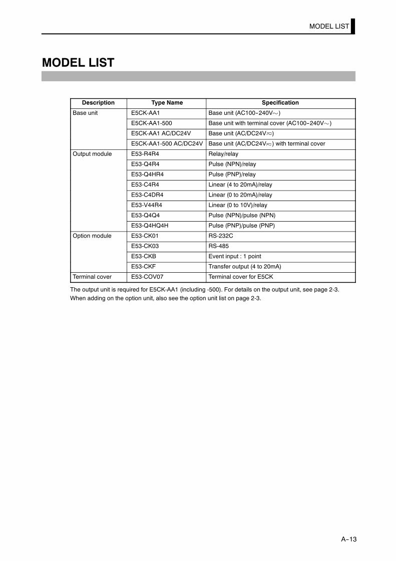
MODEL LIST
E5CK
A--13
MODEL LIST
Description Type Name Specification
Base unit E5CK-AA1 Base unit (AC100--240V )
E5CK-AA1-500 Base unit with terminal cover (AC100--240V )
E5CK-AA1 AC/DC24V Base unit (AC/DC24V )
E5CK-AA1-500 AC/DC24V Base unit (AC/DC24V ) with terminal cover
Output module E53-R4R4 Relay/relay
E53-Q4R4 Pulse (NPN)/relay
E53-Q4HR4 Pulse (PNP)/relay
E53-C4R4 Linear (4 to 20mA)/relay
E53-C4DR4 Linear (0 to 20mA)/relay
E53-V44R4 Linear (0 to 10V)/relay
E53-Q4Q4 Pulse (NPN)/pulse (NPN)
E53-Q4HQ4H Pulse (PNP)/pulse (PNP)
Option module E53-CK01 RS-232C
E53-CK03 RS-485
E53-CKB Event input : 1 point
E53-CKF Transfer output (4 to 20mA)
Terminal cover E53-COV07 Terminal cover for E5CK
The output unit is required for E5CK-AA1 (including -500). For details on the output unit, see page 2-3.When adding on the option unit, also see the option unit list on page 2-3.
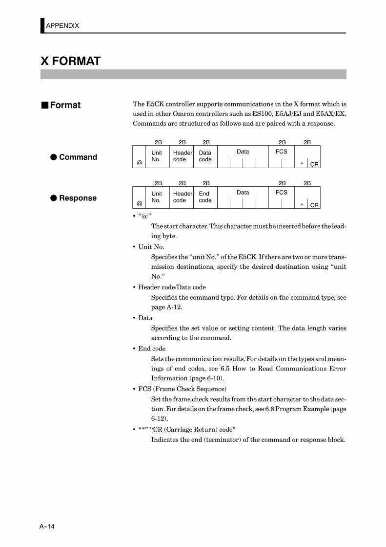
APPENDIX
E5CK
A--14
X FORMAT
The E5CK controller supports communications in the X format which isused in other Omron controllers such as ES100, E5AJ/EJ and E5AX/EX.Commands are structured as follows and are paired with a response.
Headercode
UnitNo.
FCS
CR@ *
2B 2B 2B 2B
Datacode
2B
Data
Headercode
UnitNo.
FCS
CR@ *
2B 2B 2B 2B
Endcode
2B
Data
• “@”
The start character.Thischaractermustbe insertedbefore the lead-ing byte.
• Unit No.
Specifies the “unitNo.” of theE5CK. If there are two ormore trans-mission destinations, specify the desired destination using “unitNo.”
• Header code/Data code
Specifies the command type. For details on the command type, seepage A-12.
• Data
Specifies the set value or setting content. The data length variesaccording to the command.
• End code
Sets the communication results. For details on the types andmean-ings of end codes, see 6.5 How to Read Communications ErrorInformation (page 6-10).
• FCS (Frame Check Sequence)
Set the frame check results from the start character to the data sec-tion.For details on the frame check, see 6.6ProgramExample (page6-12).
• “*” “CR (Carriage Return) code”
Indicates the end (terminator) of the command or response block.
JFormat
F Command
F Response
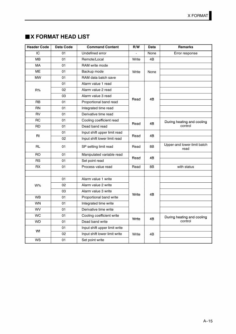
X FORMAT
E5CK
A--15
JX FORMAT HEAD LIST
Header Code Data Code Command Content R/W Data Remarks
IC 01 Undefined error - None Error response
MB 01 Remote/Local Write 4B
MA 01 RAM write mode
ME 01 Backup mode Write None
MW 01 RAM data batch save
01 Alarm value 1 read
R% 02 Alarm value 2 read
03 Alarm value 3 readRead 4B
RB 01 Proportional band readRead 4B
RN 01 Integrated time read
RV 01 Derivative time read
RC 01 Cooling coefficient readRead 4B During heating and cooling
RD 01 Dead band readRead 4B During heating and cooling
control
RI01 Input shift upper limit read
Read 4BRI02 Input shift lower limit read
Read 4B
RL 01 SP setting limit read Read 8B Upper-and lower-limit batchread
RO 01 Manipulated variable readRead 4B
RS 01 Set point readRead 4B
RX 01 Process value read Read 8B with status
01 Alarm value 1 write
W% 02 Alarm value 2 write
03 Alarm value 3 writeWrite 4B
WB 01 Proportional band writeWrite 4B
WN 01 Integrated time write
WV 01 Derivative time write
WC 01 Cooling coefficient writeWrite 4B During heating and cooling
WD 01 Dead band writeWrite 4B During heating and cooling
control
WI01 Input shift upper limit write
WI02 Input shift lower limit write Write 4B
WS 01 Set point write
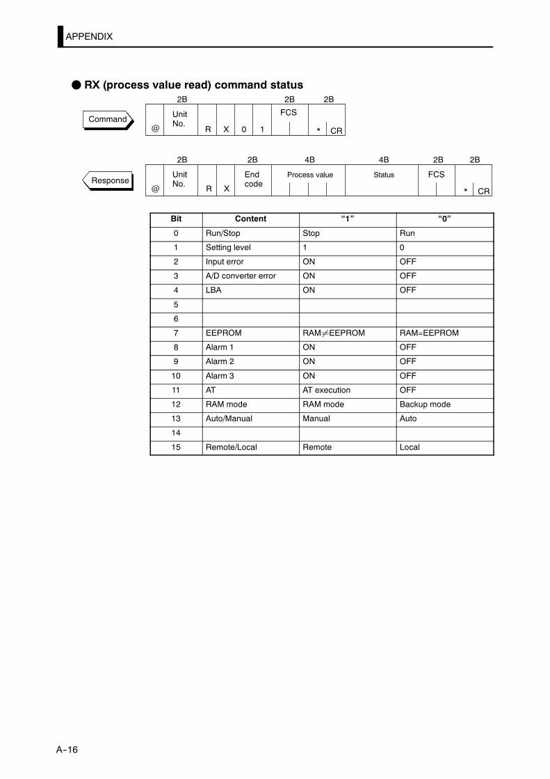
APPENDIX
E5CK
A--16
F RX (process value read) command status
Command UnitNo.
FCS
CR
UnitNo.
Process value FCS
CR
Endcode
@
@
*
*
2B 2B 2B
2B 4B 2B 2B2B
R X 0 1
RResponse
X
4B
Status
Bit Content “1” “0”
0 Run/Stop Stop Run
1 Setting level 1 0
2 Input error ON OFF
3 A/D converter error ON OFF
4 LBA ON OFF
5
6
7 EEPROM RAM¸EEPROM RAM=EEPROM
8 Alarm 1 ON OFF
9 Alarm 2 ON OFF
10 Alarm 3 ON OFF
11 AT AT execution OFF
12 RAM mode RAM mode Backup mode
13 Auto/Manual Manual Auto
14
15 Remote/Local Remote Local
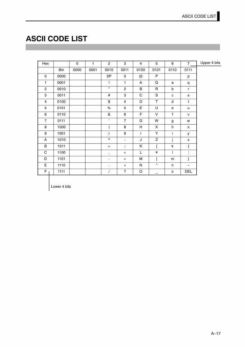
ASCII CODE LIST
E5CK
A--17
ASCII CODE LIST
Hex 0 1 2 3 4 5 6 7
Bin 0000 0001 0010 0011 0100 0101 0110 0111
0 0000 SP 0 @ P p
1 0001 ! 1 A Q a q
2 0010 ” 2 B R b r
3 0011 # 3 C S c s
4 0100 $ 4 D T d t
5 0101 % 5 E U e u
6 0110 & 6 F V f v
7 0111 ’ 7 G W g w
8 1000 ( 8 H X h x
9 1001 ) 9 I Y i y
A 1010 * : J Z j z
B 1011 + ; K [ k
C 1100 , < L ¥ l |
D 1101 - = M ] m
E 1110 . > N ^ n ~
F 1111 / ? O _ o DEL
Upper 4 bits
Lower 4 bits

INDEX
AA/D converter error 3---5,7---5. . . . . . . . . . . . .A/M key 1---3. . . . . . . . . . . . . . . . . . . . . . . . . . . . .A/M key protect 3---10. . . . . . . . . . . . . . . . . . . . .[A/M] key protect 5---4. . . . . . . . . . . . . . . . . . . .ASCII CODE LIST A---17. . . . . . . . . . . . . . . . .AT Execute/Cancel 5---10. . . . . . . . . . . . . . . . . .AT calculated gain 5---30. . . . . . . . . . . . . . . . . .AT hysteresis 5---31. . . . . . . . . . . . . . . . . . . . . . .About Calibration 1---10. . . . . . . . . . . . . . . . . . .About invalid parameters 6---7. . . . . . . . . . . . .About PID Parameters 3---14. . . . . . . . . . . . . .About the Decimal Point ofthe Alarm Value 3---9. . . . . . . . . . . . . . . . . . .
About the power blocks 2---6. . . . . . . . . . . . . . .About the event input and keyoperation[event input] 4---7. . . . . . . . . . . . .
Adjusting Control Operation 3---12. . . . . . . . .Alarm 1 hysteresis 5---19. . . . . . . . . . . . . . . . . .Alarm 1 open in alarm 5---26. . . . . . . . . . . . . . .Alarm 1 type 5---25. . . . . . . . . . . . . . . . . . . . . . .Alarm 2 hysteresis 5---19. . . . . . . . . . . . . . . . . .Alarm 2 open in alarm 5---26. . . . . . . . . . . . . . .Alarm 2 type 5---25. . . . . . . . . . . . . . . . . . . . . . .Alarm 3 hysteresis 5---19. . . . . . . . . . . . . . . . . .Alarm 3 open in alarm 5---26. . . . . . . . . . . . . . .Alarm 3 type 5---25. . . . . . . . . . . . . . . . . . . . . . .Alarm hysteresis 3---8. . . . . . . . . . . . . . . . . . . . .Alarm type 3---7. . . . . . . . . . . . . . . . . . . . . . . . . .Alarm value 3---7. . . . . . . . . . . . . . . . . . . . . . . . .Alarm value 1 3---7,5---11. . . . . . . . . . . . . . . . .Alarm value 2 3---7,5---11. . . . . . . . . . . . . . . . .Alarm value 3 3---7,5---11. . . . . . . . . . . . . . . . .Auto-tuning(A.T.) 1---3,3---13. . . . . . . . . . . . . .Auto/Manual 3---12,4---7. . . . . . . . . . . . . . . . . .Automatic return of display mode 5---31. . . . .Auxiliary output 1 assignment 5---25. . . . . . . .Auxiliary output 1[Terminal Nos.] 2---8. . . . .
BBalance-less, Bump-less Operation 3---12. . . .
CCONTROL BLOCK DIAGRAM A---5. . . . . . .Cable connections[communications] 6---3. . .Calibrating current input 4---17. . . . . . . . . . . .Calibrating inputs 1---10. . . . . . . . . . . . . . . . . .Calibrating platinum resistancethermometer 4---15. . . . . . . . . . . . . . . . . . . . . . .Calibrating thermocouple 4---12. . . . . . . . . . . .Calibrating transfer output 1---10. . . . . . . . . .
Calibrating voltage input 4---18. . . . . . . . . . . .Calibration 4---11. . . . . . . . . . . . . . . . . . . . . . . . .Calibration item menu 4---12. . . . . . . . . . . . . .Calibration mode 1---7,5---36. . . . . . . . . . . . . .Calibration save mark 4---12. . . . . . . . . . . . . . .Changing the set point 3---12. . . . . . . . . . . . . . .Checking indication accuracy 4---20. . . . . . . . .Close in alarm/open in alarm 3---8. . . . . . . . . .Command Configuration[communications] 6---5. . . . . . . . . . . . . . . . .
Commands and Responses[communications] 6---6. . . . . . . . . . . . . . . . .
Communication baud rate 5---34. . . . . . . . . . .Communication data length 5---34. . . . . . . . . .Communication parity 5---34. . . . . . . . . . . . . . .Communication stop bit 5---34. . . . . . . . . . . . .Communication unit No. 5---34. . . . . . . . . . . . .Communications parameters 6---4. . . . . . . . . .Connecting the Cold JunctionConductor 4---12. . . . . . . . . . . . . . . . . . . . . . .
Control output 1 assignment 5---24. . . . . . . . .Control output 2 assignment 5---24. . . . . . . . .Control output[Terminal Nos.] 2---7. . . . . . . .Control period 3---6. . . . . . . . . . . . . . . . . . . . . . .Control period(cool) 5---14. . . . . . . . . . . . . . . . .Control period(heat) 5---14. . . . . . . . . . . . . . . . .Cooling coefficient 4---2,5---12. . . . . . . . . . . . .Current input 1---4. . . . . . . . . . . . . . . . . . . . . . .
DDead band 4---2,5---12. . . . . . . . . . . . . . . . . . . . .Decimal point 5---23. . . . . . . . . . . . . . . . . . . . . .Derivative time 5---11. . . . . . . . . . . . . . . . . . . . .Dimensions 2---4. . . . . . . . . . . . . . . . . . . . . . . . .Direct/reverse operation 3---5,5---26. . . . . . . .Down key 1---3. . . . . . . . . . . . . . . . . . . . . . . . . . .Draw-out 2---2. . . . . . . . . . . . . . . . . . . . . . . . . . . .
EError Display 7---3. . . . . . . . . . . . . . . . . . . . . . . .Error output 7---5. . . . . . . . . . . . . . . . . . . . . . . .Event input 1---4,4---7. . . . . . . . . . . . . . . . . . . .Event input assignment 1 5---33. . . . . . . . . . . .Expansion mode 1---6,5---27. . . . . . . . . . . . . . .
FFixing settings 1---8. . . . . . . . . . . . . . . . . . . . . . .Front panel 1---2. . . . . . . . . . . . . . . . . . . . . . . . .
HHeating and cooling control 4---2. . . . . . . . . . .How to Read CommunicationsError Information 6---10. . . . . . . . . . . . . . . .

INDEX
How to Use Option Functions 4---7. . . . . . . . .How to use keys 1---3. . . . . . . . . . . . . . . . . . . . . .Hysteresis 4---3. . . . . . . . . . . . . . . . . . . . . . . . . . .Hysteresis(cool) 5---13. . . . . . . . . . . . . . . . . . . . .Hysteresis(heat) 5---13. . . . . . . . . . . . . . . . . . . .
IInput and Output 1---4. . . . . . . . . . . . . . . . . . . .Input assignments 4---7. . . . . . . . . . . . . . . . . . .Input digital filter 5---19. . . . . . . . . . . . . . . . . . .Input errors 7---5. . . . . . . . . . . . . . . . . . . . . . . . .Input shift 3---3. . . . . . . . . . . . . . . . . . . . . . . . . .Input shift lower limit 3---3,5---20. . . . . . . . . .Input shift upper limit 3---3,5---20. . . . . . . . . .Input type 3---3,5---22. . . . . . . . . . . . . . . . . . . . .Input [Terminal Nos.] 2---6. . . . . . . . . . . . . . . .Installation 2---4. . . . . . . . . . . . . . . . . . . . . . . . . .Integral time 5---11. . . . . . . . . . . . . . . . . . . . . . .Interface 6---2. . . . . . . . . . . . . . . . . . . . . . . . . . . .Issuing special commands 6---9. . . . . . . . . . . . .
LLBA 4---9,7---5. . . . . . . . . . . . . . . . . . . . . . . . . . .LBA detection example 4---9. . . . . . . . . . . . . . .LBA detection time 4---9,5---17. . . . . . . . . . . . .LBA detection width 4---9,5---31. . . . . . . . . . .Level 0 mode 1---6,5---6. . . . . . . . . . . . . . . . . . .Level 1 mode 1---6,5---9. . . . . . . . . . . . . . . . . . .Level 2 mode 1---6,5---15. . . . . . . . . . . . . . . . . .Limiter operation conditions 4---5. . . . . . . . . .
MMANU 1---3. . . . . . . . . . . . . . . . . . . . . . . . . . . . . .MV at PV error 5---17. . . . . . . . . . . . . . . . . . . . .MV change rate limit 5---18. . . . . . . . . . . . . . . .MV change rate limiter 4---4. . . . . . . . . . . . . . .MV limiter 4---4. . . . . . . . . . . . . . . . . . . . . . . . . .MV lower limit 5---18. . . . . . . . . . . . . . . . . . . . .MV monitor(cool) 5---7. . . . . . . . . . . . . . . . . . . .MV monitor(heat) 5---7. . . . . . . . . . . . . . . . . . . .MV upper limit 5---18. . . . . . . . . . . . . . . . . . . . .Main parts 1---2. . . . . . . . . . . . . . . . . . . . . . . . . .Manipulated variable at stop 3---11,4---2. . . .Manipulated variable restrictions 4---4. . . . . .Manual MV 5---5. . . . . . . . . . . . . . . . . . . . . . . . .Manual mode 1---6,5---5. . . . . . . . . . . . . . . . . . .Manual operation 3---12. . . . . . . . . . . . . . . . . . .Manual reset value 5---13. . . . . . . . . . . . . . . . . .Menu display 1---7. . . . . . . . . . . . . . . . . . . . . . . .Mode key 1---3. . . . . . . . . . . . . . . . . . . . . . . . . . . .Model List A---13. . . . . . . . . . . . . . . . . . . . . . . . .
Mounting 2---5. . . . . . . . . . . . . . . . . . . . . . . . . . .Multi-SP 4---8. . . . . . . . . . . . . . . . . . . . . . . . . . . .Multi-SP function 5---33. . . . . . . . . . . . . . . . . . .
NNames of parts 1---2. . . . . . . . . . . . . . . . . . . . . .No. 1 display 1---3. . . . . . . . . . . . . . . . . . . . . . . .No. 2 display 1---3. . . . . . . . . . . . . . . . . . . . . . . .
OON/OFF control 4---3. . . . . . . . . . . . . . . . . . . . .OUT1 1---3. . . . . . . . . . . . . . . . . . . . . . . . . . . . . .OUT2 1---3. . . . . . . . . . . . . . . . . . . . . . . . . . . . . .Operating Condition Restrictions 4---4. . . . . .Operation at start [SP ramp] 4---6. . . . . . . . . .Operation indicators 1---3. . . . . . . . . . . . . . . . .Option mode 1---7,5---32. . . . . . . . . . . . . . . . . .Option [Terminal Nos.] 2---8. . . . . . . . . . . . . . .Output assignments 1---5,3---5. . . . . . . . . . . . .
PPARAMETER OPERATIONS LIST A---8. . .PARAMETERS 5---1. . . . . . . . . . . . . . . . . . . . . .PID/ON/OFF 5---28. . . . . . . . . . . . . . . . . . . . . . .PV/SP 5---6. . . . . . . . . . . . . . . . . . . . . . . . . . . . . .Panel cutout 2---4. . . . . . . . . . . . . . . . . . . . . . . . .Parameter initialize 5---23. . . . . . . . . . . . . . . . .Parameter types 1---6. . . . . . . . . . . . . . . . . . . . .Parameters and Menus 1---6. . . . . . . . . . . . . . .Platinum resistance thermometer 4---20. . . .Precautions when wiring 2---6. . . . . . . . . . . . .Proportional band 5---11. . . . . . . . . . . . . . . . . .Protect mode 1---6,3---10,5---3. . . . . . . . . . . . . .
RRMT 1---3. . . . . . . . . . . . . . . . . . . . . . . . . . . . . . .RS---232C 1---9,6---3. . . . . . . . . . . . . . . . . . . . . .RS---485 1---9,6---3. . . . . . . . . . . . . . . . . . . . . . . .Reading the status [communications] 6---8. .Reading/writing parameters 6---6. . . . . . . . . . .Registering calibration data 1---10. . . . . . . . . .Remote/Local 5---16. . . . . . . . . . . . . . . . . . . . . . .Restrictions during SP ramp 4---6. . . . . . . . . .Run/Stop 4---7,5---8. . . . . . . . . . . . . . . . . . . . . . .
SSETTING LIST A---6. . . . . . . . . . . . . . . . . . . .SP ramp 4---5. . . . . . . . . . . . . . . . . . . . . . . . . . . .SP ramp set value 5---16. . . . . . . . . . . . . . . . . . .SP ramp time unit 5---16. . . . . . . . . . . . . . . . . .SP setting lower limit 5---28. . . . . . . . . . . . . . .SP setting upper limit 5---28. . . . . . . . . . . . . . .

INDEX
SPECIFICATIONS A---2. . . . . . . . . . . . . . . . . .ST 5---29. . . . . . . . . . . . . . . . . . . . . . . . . . . . . . . . .ST stable range 5---29. . . . . . . . . . . . . . . . . . . . .STOP 1---3. . . . . . . . . . . . . . . . . . . . . . . . . . . . . . .SUB1 1---3. . . . . . . . . . . . . . . . . . . . . . . . . . . . . . .Scaling 3---3. . . . . . . . . . . . . . . . . . . . . . . . . . . . . .Scaling lower limit 5---23. . . . . . . . . . . . . . . . . .Scaling upper limit 5---23. . . . . . . . . . . . . . . . . .Security 3---10,5---3. . . . . . . . . . . . . . . . . . . . . . .Selecting modes 1---7. . . . . . . . . . . . . . . . . . . . . .Selecting parameters 1---8. . . . . . . . . . . . . . . . .Selecting the Control Method 4---2. . . . . . . . . .Set point 0 5---10. . . . . . . . . . . . . . . . . . . . . . . . .Set point 1 5---10. . . . . . . . . . . . . . . . . . . . . . . . .Set point during SP ramp 5---7. . . . . . . . . . . . .Set point limiter 4---5. . . . . . . . . . . . . . . . . . . . .Setting Alarm Type 3---7. . . . . . . . . . . . . . . . . .Setting Input Specifications 3---3. . . . . . . . . . .Setting Output Specifications 3---5. . . . . . . . .Setting the communicationsspecifications 6---4. . . . . . . . . . . . . . . . . . . . .
Setting the input type 2---2. . . . . . . . . . . . . . . .Setting up 2---2. . . . . . . . . . . . . . . . . . . . . . . . . . .Setup mode 1---6,5---21. . . . . . . . . . . . . . . . . . . .Standby sequence 3---8. . . . . . . . . . . . . . . . . . . .Standby sequence reset method 5---30. . . . . . .Starting and Stopping Operation 3---11. . . . .
Summary of alarm operations 3---8. . . . . . . . .
TTROUBLESHOOTING 7---1. . . . . . . . . . . . . . .Temperature input 1---4. . . . . . . . . . . . . . . . . . .Terminal arrangement 2---6. . . . . . . . . . . . . . .Thermocouple 4---20. . . . . . . . . . . . . . . . . . . . . .Transfer output 1---5,4---8. . . . . . . . . . . . . . . . .Transfer output lower limit 5---35. . . . . . . . . .Transfer output type 5---35. . . . . . . . . . . . . . . .Transfer output upper limit 5---35. . . . . . . . . .Transfer procedure [communications] 6---2. .
UUp key 1---3. . . . . . . . . . . . . . . . . . . . . . . . . . . . .
VVoltage input 1---4. . . . . . . . . . . . . . . . . . . . . . . .
WWiring Terminals 2---6. . . . . . . . . . . . . . . . . . . .Writing the Set Value 6---6. . . . . . . . . . . . . . . . .
XX FORMAT A---14. . . . . . . . . . . . . . . . . . . . . . .
°C/°F selection 5---24. . . . . . . . . . . . . . . . . . . . . .α 5---29. . . . . . . . . . . . . . . . . . . . . . . . . . . . . . . . . .
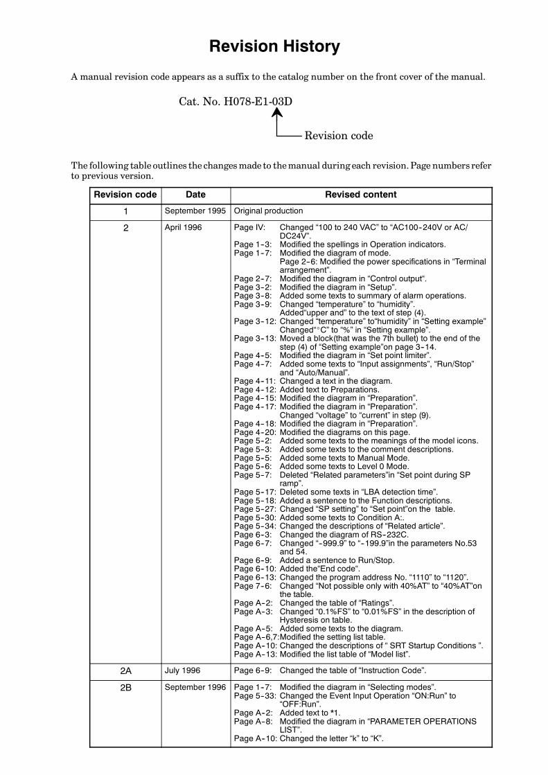
Revision History
A manual revision code appears as a suffix to the catalog number on the front cover of the manual.
Cat. No. H078-E1-03D
Revision code
The following table outlines the changesmade to themanual during each revision.Page numbers referto previous version.
Revision code Date Revised content
1 September 1995 Original production
2 April 1996 Page IV: Changed “100 to 240 VAC” to “AC100--240V or AC/DC24V”.
Page 1--3: Modified the spellings in Operation indicators.Page 1--7: Modified the diagram of mode.
Page 2--6: Modified the power specifications in “Terminalarrangement”.
Page 2--7: Modified the diagram in “Control output“.Page 3--2: Modified the diagram in “Setup”.Page 3--8: Added some texts to summary of alarm operations.Page 3--9: Changed “temperature” to “humidity”.
Added“upper and” to the text of step (4).Page 3--12: Changed “temperature” to“humidity” in “Setting example”
Changed“_C” to “%” in “Setting example”.Page 3--13: Moved a block(that was the 7th bullet) to the end of the
step (4) of “Setting example”on page 3--14.Page 4--5: Modified the diagram in “Set point limiter”.Page 4--7: Added some texts to “Input assignments”, “Run/Stop”
and “Auto/Manual”.Page 4--11: Changed a text in the diagram.Page 4--12: Added text to Preparations.Page 4--15: Modified the diagram in “Preparation”.Page 4--17: Modified the diagram in “Preparation”.
Changed “voltage” to “current” in step (9).Page 4--18: Modified the diagram in “Preparation”.Page 4--20: Modified the diagrams on this page.Page 5--2: Added some texts to the meanings of the model icons.Page 5--3: Added some texts to the comment descriptions.Page 5--5: Added some texts to Manual Mode.Page 5--6: Added some texts to Level 0 Mode.Page 5--7: Deleted “Related parameters”in “Set point during SP
ramp”.Page 5--17: Deleted some texts in “LBA detection time”.Page 5--18: Added a sentence to the Function descriptions.Page 5--27: Changed “SP setting” to “Set point”on the table.Page 5--30: Added some texts to Condition A:.Page 5--34: Changed the descriptions of “Related article”.Page 6--3: Changed the diagram of RS--232C.Page 6--7: Changed “--999.9” to “--199.9”in the parameters No.53
and 54.Page 6--9: Added a sentence to Run/Stop.Page 6--10: Added the“End code“.Page 6--13: Changed the program address No. “1110” to “1120”.Page 7--6: Changed “Not possible only with 40%AT” to “40%AT”on
the table.Page A--2: Changed the table of “Ratings”.Page A--3: Changed “0.1%FS” to “0.01%FS” in the description of
Hysteresis on table.Page A--5: Added some texts to the diagram.Page A--6,7:Modified the setting list table.Page A--10: Changed the descriptions of “ SRT Startup Conditions ”.Page A--13: Modified the list table of “Model list”.
2A July 1996 Page 6--9: Changed the table of “Instruction Code”.
2B September 1996 Page 1--7: Modified the diagram in “Selecting modes”.Page 5--33: Changed the Event Input Operation “ON:Run” to
“OFF:Run”.Page A--2: Added text to *1.Page A--8: Modified the diagram in “PARAMETER OPERATIONS
LIST”.Page A--10: Changed the letter “k” to “K”.

Revision code Revised contentDate
3 April 1997 Page 1--7: Added text to Menu display.Page 2--7: Deleted the Specifications of 0 to 20mA on the table of
“Control output”.Page 3--4: Added “1 second min.” to the display flowchart.Page 3--6: Added text to Control period.
Changed “control period” to “control period (heat) ” in“Setting Example”.Added “1 second min.” to the display flowchart.Changed “control period” to “control period (heat)” in step(8).
Page 3--9: Added “1 second min.” to the display flowchart.Page 3--11: Changed “(--5.0 to 105.0%)” to “(Standard:--5.0 to
105.0%, Heating and Cooling:--105.0 to 105.0%)” inManipulated variable at stop.Added “1 second min.” to the display flowchart.
Page 3--12: Deleted the display of “Changing the set point”.Added a display and some texts to Manual operation.
Page 3--13: Added a display to 40%AT.Page 3--14: Added a display to 100%AT.
Added “1 second min.” to the display flowchart.Page 4--2: Moved the title of Heating and cooling control”.
Added some texts to “Heating and cooling control”.Page 4--4: Modified the lower figure for “MV limiter”.Page 4--7: Moved “Run/Stop, Auto/Manual, Reference” to page
4--8.Moved “Multi--SP” on page 4--8 to 4--7.
Page 4--8: Moved “Run/Stop, Auto/Manual, Reference” on page4--7 to 4--8.Moved “Multi--SP” on page 4--7.Added “Factory setting is Set point” to Transfer output.Added the title of “Transfer output scaling”.
Page 4--10: Deleted (4) in Determining the LBA detection time.Page 4--15: Modified display flowchart.Page 4--17: Added “Conditions of Use” to MV at stop.Page 5--27: Deleted “resetting the parameters” in the sixth lines from
the top.Page 5--29: Added “Usually use the default value.” to α.Page 5--30: Added “Usually use the default value.” to AT calculated
gain.Added a figure to “Standby sequence reset method”.
Page 5--31: Added “Usually use the default value.” to AT hysteresis.Page 5--35: Added some texts to the table.
Deleted “When you have selected the “manipulated vari-able (heat)” parameter, the transfer output lower limitduring heating and cooling control becomes “0.0””.
Page 6--11: Deleted “End code12”.Page 7--5: Added “(auxiliary output 1)” to Input errors and A/D con-
verter error.Page A--4: Modified the table of “Output Unit Ratings and Character-
istics”.Page A--5: Modified the diagram.Page A--6: Added Remarks to the Parameter of “Remote/Local”.Page A--7: Changed the description “--5.0 to 105.0%” of “O” in
Transfer Output Type to “Standard:--50. To 105.0%,Heating and cooling:0.0 to 105.0%.Deleted two lines of the texts from the bottom.
Page A--10: Deleted 2) of “At the time the E5CK starts operation” in“Startup Conditions of SRT”.Deleted 2) of “At the time set point is changed”.
Page A--11: Deleted “Imposition Completion Condition of Step Con-trol Amount”.Modified figure in “PID Constant Refreshing Conditions”.
Page A--13: Changed “Type Name” and “Specification” in “Base unit”.Page A--14: Added some texts to “Format”.
Modified the diagram in “Command”.Modified “X FORMAT HEAD LIST”.Added “Note”.
3A April 1998 Page 3--5: Added a sentence to “Output assignments”.Page A--7: Changed “OR--R/OR--D” to “OR--D/OR--R” in the middle
of the page.
03B March 2004 Page 5--3: Changed the bottom table.Page A--6: Add “FS” to the “Unit” column in three cells toward the
bottom of the table.
03C December 2004 Page A-3: Added information to table and accompanying notes.
03D August 2006 Page 5-8: Changed description of key operation in second bulleteditem.

E5C
KD
igital C
on
troller
User's M
anu
alC
at. No
. H078-E
1-03D
Authorized Distributor:
Cat. No. H078-E1-03D Note: Specifications subject to change without notice. Printed in Japan
0806-0.2M (1096) (B)
DIC182 K
OMRON CorporationIndustrial Automation Company
Control Devices Division H.Q.Analog Controller DivisionShiokoji Horikawa, Shimogyo-ku,Kyoto, 600-8530 JapanTel: (81)75-344-7080/Fax: (81)75-344-7189
Regional Headquarters
OMRON EUROPE B.V.Wegalaan 67-69, NL-2132 JD HoofddorpThe NetherlandsTel: (31)2356-81-300/Fax: (31)2356-81-388
OMRON ELECTRONICS LLC1 East Commerce Drive, Schaumburg, IL 60173U.S.A.Tel: (1)847-843-7900/Fax: (1)847-843-8568
OMRON ASIA PACIFIC PTE. LTD.83 Clemenceau Avenue, #11-01, UE Square,239920 SingaporeTel: (65)6835-3011/Fax: (65)6835-2711
OMRON (CHINA) CO., LTD. Room 2211, Bank of China Tower, 200 Yin Cheng Road (M), Shanghai, 200120 ChinaTel: (86)21-5037-2222/Fax: (86)21-5037-2200