Embed Size (px)
Citation preview
EAGLE Controller Product Data
® U.S. Registered Trademark
Copyright © 2014 Honeywell Inc. • All Rights Reserved EN0Z-0970GE51 R0214
GENERAL EAGLE is CentraLine’s Ethernet-based, freely-programmable Building Automation controller offering a combination of BACnet IP, BACnet MS/TP, and LONWORKS® communication. It demonstrates CentraLine’s full commitment to reducing total installed cost and total building lifecycle cost for building investors and building operators. EAGLE incorporates the major open standards of today’s building industry: BACnet®, LONWORKS®, Modbus, and M-Bus. As a native BACnet® Building Controller (B-BC), EAGLE integrates into any 3rd-party BACnet® system with low and predictable effort. Furthermore, EAGLE (in combination with the IF-LON) is a full LONWORKS® controller. This gives the benefit of making use of CentraLine’s complete LONWORKS® product portfolio, which is unique in the building industry. EAGLE can host a huge variety of building management applications, be it traditional heating, ventilation, and air conditioning (HVAC) applications, energy management functions, including optimum start/stop, night purge, and maximum load demand, supervisory functions for lighting, sun-blind, heat and energy metering and many other applications. By virtue of its "peer-to-peer" concept, EAGLE is not dependent upon the availability of superordinate centrals or application network controllers. EAGLE seamlessly integrates into CentraLine’s ARENA AX and SymmetrE® front-ends.
3RD-PARTY SOFTWARE LICENSES This product contains software provided by third parties. See also EAGLE Controller – Third-Party Software Licenses (Product Literature No.: EN2Z-0991GE51).
FEATURES Reduced the total installed cost:
Existing standard Ethernet/LAN infrastructure is used for communication between EAGLE controllers, 3rd-party BACnet® controllers, and BACnet® front-ends. Costs are further reduced by the flexible and optional use of onboard I/Os and Panel Bus I/Os.
Universal operation: Via Internet browser, the EAGLE can be operated from any place, from any PC connected to the (EAGLE) network! An integrated web-server allows local and remote operation by standard browsers.
NETWORK SECURITY When operating the EAGLE in IP networks, either private (e.g., VPN) networks must be used or protection against the open Internet (e.g., by means of external firewalls) must be ensured. See "Network Security" on pg. 6.
Reduced cost for service, operation and maintenance: Maintenance or upgrade of Operator Interface Software is superfluous because it resides in EAGLE, itself (single-source principle).
Vendor independence: Communication is based on the following international standards: BACnet/IP (ISO 16484-5); BACnet MS/TP (ISO 16484-5); LONWORKS (ISO 14908); Modbus RTU Master; M-Bus (EN 1434-3).
Trending: 100 datapoints can be trended.
Fast application control: Four selectable control loop priorities (multitasking), selectable control loop cycle times, and event-driven switching tables allow for tailored and highly effective applications control.
Reliable control performance: Embedded LINUX ensures reliable, independent, and secure operation, especially for systems with Internet access.
Embedded e-mail/SMS alarming: Configurable e-mail alarming options allow alarms to be sent (via network or Internet-DSL connection) to e-mail accounts and thus also to mobile phones.
CentraLine CARE tool: Allows re-use of existing applications and application macros, enables highly effective application generation, and supports online application debugging.
Flexible mounting options: Mounting onto wall or onto panel back wall, into panel door, onto panel rail, and into sub-panels (fuse boxes).
EAGLE CONTROLLER – PRODUCT DATA
EN0Z-0970GE51 R0214 2
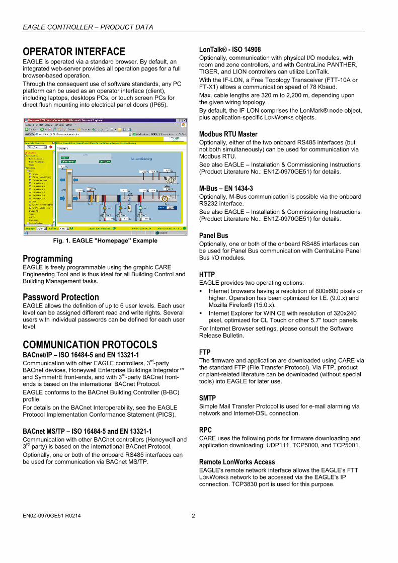
OPERATOR INTERFACE EAGLE is operated via a standard browser. By default, an integrated web-server provides all operation pages for a full browser-based operation. Through the consequent use of software standards, any PC platform can be used as an operator interface (client), including laptops, desktops PCs, or touch screen PCs for direct flush mounting into electrical panel doors (IP65).
Fig. 1. EAGLE "Homepage" Example
Programming EAGLE is freely programmable using the graphic CARE Engineering Tool and is thus ideal for all Building Control and Building Management tasks.
Password Protection EAGLE allows the definition of up to 6 user levels. Each user level can be assigned different read and write rights. Several users with individual passwords can be defined for each user level.
COMMUNICATION PROTOCOLS BACnet/IP – ISO 16484-5 and EN 13321-1 Communication with other EAGLE controllers, 3rd-party BACnet devices, Honeywell Enterprise Buildings Integrator™ and SymmetrE front-ends, and with 3rd-party BACnet front-ends is based on the international BACnet Protocol. EAGLE conforms to the BACnet Building Controller (B-BC) profile. For details on the BACnet Interoperability, see the EAGLE Protocol Implementation Conformance Statement (PICS).
BACnet MS/TP – ISO 16484-5 and EN 13321-1 Communication with other BACnet controllers (Honeywell and 3rd-party) is based on the international BACnet Protocol. Optionally, one or both of the onboard RS485 interfaces can be used for communication via BACnet MS/TP.
LonTalk® - ISO 14908 Optionally, communication with physical I/O modules, with room and zone controllers, and with CentraLine PANTHER, TIGER, and LION controllers can utilize LonTalk. With the IF-LON, a Free Topology Transceiver (FTT-10A or FT-X1) allows a communication speed of 78 Kbaud. Max. cable lengths are 320 m to 2,200 m, depending upon the given wiring topology. By default, the IF-LON comprises the LonMark® node object, plus application-specific LONWORKS objects.
Modbus RTU Master Optionally, either of the two onboard RS485 interfaces (but not both simultaneously) can be used for communication via Modbus RTU. See also EAGLE – Installation & Commissioning Instructions (Product Literature No.: EN1Z-0970GE51) for details.
M-Bus – EN 1434-3 Optionally, M-Bus communication is possible via the onboard RS232 interface. See also EAGLE – Installation & Commissioning Instructions (Product Literature No.: EN1Z-0970GE51) for details.
Panel Bus Optionally, one or both of the onboard RS485 interfaces can be used for Panel Bus communication with CentraLine Panel Bus I/O modules.
HTTP EAGLE provides two operating options: Internet browsers having a resolution of 800x600 pixels or
higher. Operation has been optimized for I.E. (9.0.x) and Mozilla Firefox® (15.0.x).
Internet Explorer for WIN CE with resolution of 320x240 pixel, optimized for CL Touch or other 5.7" touch panels.
For Internet Browser settings, please consult the Software Release Bulletin.
FTP The firmware and application are downloaded using CARE via the standard FTP (File Transfer Protocol). Via FTP, product or plant-related literature can be downloaded (without special tools) into EAGLE for later use.
SMTP Simple Mail Transfer Protocol is used for e-mail alarming via network and Internet-DSL connection.
RPC CARE uses the following ports for firmware downloading and application downloading: UDP111, TCP5000, and TCP5001.
Remote LonWorks Access EAGLE's remote network interface allows the EAGLE's FTT LONWORKS network to be accessed via the EAGLE's IP connection. TCP3830 port is used for this purpose.
EAGLE CONTROLLER – PRODUCT DATA
EN0Z-0970GE51 R0214 3
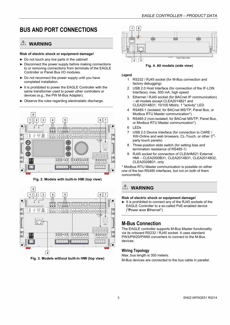
BUS AND PORT CONNECTIONS
WARNING
Risk of electric shock or equipment damage!
Do not touch any live parts in the cabinet! Disconnect the power supply before making connections
to or removing connections from terminals of the EAGLE Controller or Panel Bus I/O modules.
Do not reconnect the power supply until you have completed installation.
It is prohibited to power the EAGLE Controller with the same transformer used to power other controllers or devices (e.g., the PW M-Bus Adapter).
Observe the rules regarding electrostatic discharge.
BI1
BI2
BI3
BI4
GN
D
UI1
UI2
UI3
UI4
UI5
UI6
UI7
24 25 26 27 28 29 30 31 32 33 34 35 36 37 38 39 40 41 42 43 44 45 46
UI8
47
DO
1
DO
2
DO
3
IN IN4
DO
4
DO
5
IN5
IN6
DO
6
DO
7
IN7
IN8
DO
8
GN
D
AO
1
AO
2
AO
3
5 6 7 8 9 10 11 12 13 14 15 16 17 18 19 20 21 22
24V-
0
24V~
1
AO
4
23
6 74 5
GN
D1
485-
1+
485-
1-
GN
D2
485-
2+
485-
2-
UI9
UI1
0
2
1
8
2 3
RS
23
2
RS485-1
END
BIA
SM
ID
Fig. 2. Models with built-in HMI (top view)
BI1
BI2
BI3
BI4
GN
D
UI1
UI2
UI3
UI4
UI5
UI6
UI7
24 25 26 27 28 29 30 31 32 33 34 35 36 37 38 39 40 41 42 43 44 45 46
UI8
47
DO
1
DO
2
DO
3
IN IN4
DO
4
DO
5
IN5
IN6
DO
6
DO
7
IN7
IN8
DO
8
GN
D
AO
1
AO
2
AO
3
5 6 7 8 9 10 11 12 13 14 15 16 17 18 19 20 21 22
24V-
0
24V~
1
AO
4
23
6 74 5
GN
D1
485-
1+
485-
1-
n.a
.
n.a
.
GN
D2
485-
2+
485-
2-
n.a
.
UI9
UI1
0
2
9
J1 J8
1
8
2 3
RS
23
2
RS485-1
END
BIA
SM
ID
Fig. 3. Models without built-in HMI (top view)
1 8
3
J1 J8
END
BIA
SM
ID
2 Fig. 4. All models (side view)
Legend 1 RS232 / RJ45 socket (for M-Bus connection and
factory debugging) 2 USB 2.0 Host Interface (for connection of the IF-LON
Interface); max. 500 mA, high speed 3 Ethernet / RJ45 socket (for BACnet IP communication)
– all models except CLEA2014B21 and CLEA2014B31; 10/100 Mbit/s; 1 "activity" LED
4 RS485-1 (isolated; for BACnet MS/TP, Panel Bus, or Modbus RTU Master communication*)
5 RS485-2 (non-isolated; for BACnet MS/TP, Panel Bus, or Modbus RTU Master communication*)
6 LEDs 7 USB 2.0 Device Interface (for connection to CARE /
XW-Online and web browsers, CL-Touch, or other 3rd-party touch panels)
8 Three-position slide switch (for setting bias and termination resistance of RS485-1)
9 RJ45 socket for connection of CLEAHMI21 External HMI – CLEA2000B31, CLEA2014B31, CLEA2014B32, CLEA2026B31, only
* Modbus RTU Master communication is possible on either one of the two RS485 interfaces, but not on both of them concurrently.
WARNING
Risk of electric shock or equipment damage! It is prohibited to connect any of the RJ45 sockets of the
EAGLE Controller to a so-called PoE-enabled device ("Power over Ethernet").
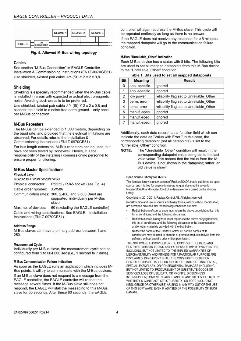
M-Bus Connection The EAGLE controller supports M-Bus Master functionality via its onboard RS232 / RJ45 socket. It uses standard PW3/PW20/PW60 converters to connect to the M-Bus devices.
Wiring Topology Max. bus length is 350 meters. M-Bus devices are connected to the bus cable in parallel.
EAGLE CONTROLLER – PRODUCT DATA
EN0Z-0970GE51 R0214 4
EAGLE
SLAVE 1 SLAVE 2 SLAVE 3
PWCONVERTER
Fig. 5. Allowed M-Bus wiring topology
Cables See section "M-Bus Connection" in EAGLE Controller – Installation & Commissioning Instructions (EN1Z-0970GE51). Use shielded, twisted pair cable J-Y-(St)-Y 2 x 2 x 0,8.
Shielding Shielding is especially recommended when the M-Bus cable is installed in areas with expected or actual electromagnetic noise. Avoiding such areas is to be preferred. Use shielded, twisted pair cable J-Y-(St)-Y 2 x 2 x 0,8 and connect the shield to a noise-free earth ground – only once per M-Bus connection.
M-Bus Repeaters The M-Bus can be extended to 1,000 meters, depending on the baud rate, and provided that the electrical limitations are observed. For details refer to the Installation & Commissioning Instructions (EN1Z-0970GE51). For bus length extension, M-Bus repeaters can be used, but have not been tested by Honeywell. Hence, it is the responsibility of the installing / commissioning personnel to ensure proper functioning.
M-Bus Master Specifications Physical Layer RS232 to PW3/PW20/PW60 Physical connector: RS232 / RJ45 socket (see Fig. 4) Cable order number: XW586 Communication rates: 300, 2,400, and 9,600 Baud are
supported, individually per M-Bus slave.
Max. no. of devices: 60 (excluding the EAGLE controller) Cable and wiring specifications: See EAGLE – Installation Instructions (EN1Z-0970GE51). Address Range M-Bus slaves can have a primary address between 1 and 250. Measurement Cycle Individually per M-Bus slave, the measurement cycle can be configured from 1 to 604,800 sec (i.e., 1 second to 7 days). M-Bus Communication Failure Indication As soon as the EAGLE runs an application which includes M-Bus points, it will try to communicate with the M-Bus devices. If an M-Bus slave does not respond to a message from the EAGLE controller, the EAGLE controller will repeat the message several times. If the M-Bus slave still does not respond, the EAGLE will stall the messaging to this M-Bus slave for 60 seconds. After these 60 seconds, the EAGLE
controller will again address the M-Bus slave. This cycle will be repeated endlessly as long as there is no answer. If the EAGLE does not receive any response for ≥ 5 minutes, the mapped datapoint will go to the communication failure condition. M-Bus "Unreliable_Other" Indication Each M-Bus device has a status with 8 bits. The following bits are used to set all mapped datapoints from this M-Bus device to the "Unreliable_Other" condition.
Table 1. Bits used to set all mapped datapoints
Bit Meaning Result
0 app.-specific ignored
1 app.-specific ignored
2 low power reliability flag set to Unreliable_Other
3 perm. error reliability flag set to Unreliable_Other
4 temp. error reliability flag set to Unreliable_Other
5 manuf.-spec. ignored
6 manuf.-spec. ignored
7 manuf.-spec. ignored
Additionally, each data record has a function field which can indicate the data as "Value with Error." In this case, the corresponding datapoint (not all datapoints) is set to the "Unreliable_Other" condition.
NOTE: The "Unreliable_Other" condition will result in the corresponding datapoint value being set to the last valid value. This means that the value from the M-Bus device is not shown in the datapoint; rather, an old value is shown.
Open Source Library for M-Bus The libmbus library is a component of RaditexSCADA that is published as open source, and it is free for anyone to use as long as due credit is given to RaditexSCADA and Raditex Control in derivative work based on the libmbus library. Copyright (c) 2010-2011, Raditex Control AB. All rights reserved. Redistribution and use in source and binary forms, with or without modification, are permitted provided that the following conditions are met: • Redistributions of source code must retain the above copyright notice, this
list of conditions, and the following disclaimer. • Redistributions in binary form must reproduce the above copyright notice,
this list of conditions, and the following disclaimer in the documentation and/or other materials provided with the distribution.
• Neither the name of the Raditex Control AB nor the names of its contributors may be used to endorse or promote products derived from this software without specific prior written permission.
THIS SOFTWARE IS PROVIDED BY THE COPYRIGHT HOLDERS AND CONTRIBUTORS "AS IS," AND ANY EXPRESS OR IMPLIED WARRANTIES, INCLUDING, BUT NOT LIMITED TO, THE IMPLIED WARRANTIES OF MERCHANTABILITY AND FITNESS FOR A PARTICULAR PURPOSE ARE DISCLAIMED. IN NO EVENT SHALL THE COPYRIGHT HOLDER OR CONTRIBUTORS BE LIABLE FOR ANY DIRECT, INDIRECT, INCIDENTAL, SPECIAL, EXEMPLARY, OR CONSEQUENTIAL DAMAGES (INCLUDING, BUT NOT LIMITED TO, PROCUREMENT OF SUBSTITUTE GOODS OR SERVICES; LOSS OF USE, DATA, OR PROFITS; OR BUSINESS INTERRUPTION) HOWEVER CAUSED AND ON ANY THEORY OF LIABILITY, WHETHER IN CONTRACT, STRICT LIABILITY, OR TORT (INCLUDING NEGLIGENCE OR OTHERWISE) ARISING IN ANY WAY OUT OF THE USE OF THIS SOFTWARE, EVEN IF ADVISED OF THE POSSIBILITY OF SUCH DAMAGE.
EAGLE CONTROLLER – PRODUCT DATA
EN0Z-0970GE51 R0214 5
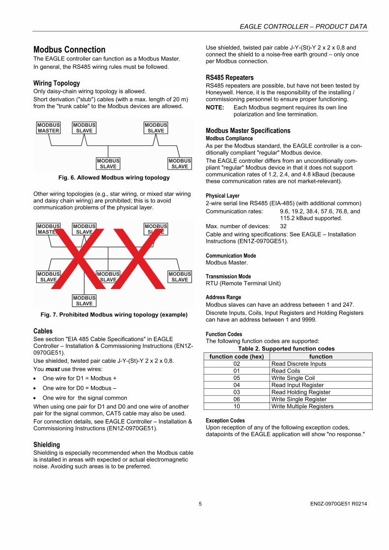
Modbus Connection The EAGLE controller can function as a Modbus Master. In general, the RS485 wiring rules must be followed.
Wiring Topology Only daisy-chain wiring topology is allowed. Short derivation ("stub") cables (with a max. length of 20 m) from the "trunk cable" to the Modbus devices are allowed.
MODBUSMASTER
MODBUSSLAVE
MODBUSSLAVE
MODBUSSLAVE
MODBUSSLAVE
Fig. 6. Allowed Modbus wiring topology
Other wiring topologies (e.g., star wiring, or mixed star wiring and daisy chain wiring) are prohibited; this is to avoid communication problems of the physical layer.
MODBUSMASTER
MODBUSSLAVE
MODBUSSLAVE
MODBUSSLAVE
MODBUSSLAVE
MODBUSSLAVE
MODBUSSLAVE
Fig. 7. Prohibited Modbus wiring topology (example)
Cables See section "EIA 485 Cable Specifications" in EAGLE Controller – Installation & Commissioning Instructions (EN1Z-0970GE51). Use shielded, twisted pair cable J-Y-(St)-Y 2 x 2 x 0,8.
You must use three wires:
One wire for D1 = Modbus +
One wire for D0 = Modbus –
One wire for the signal common
When using one pair for D1 and D0 and one wire of another pair for the signal common, CAT5 cable may also be used. For connection details, see EAGLE Controller – Installation & Commissioning Instructions (EN1Z-0970GE51).
Shielding Shielding is especially recommended when the Modbus cable is installed in areas with expected or actual electromagnetic noise. Avoiding such areas is to be preferred.
Use shielded, twisted pair cable J-Y-(St)-Y 2 x 2 x 0,8 and connect the shield to a noise-free earth ground – only once per Modbus connection.
RS485 Repeaters RS485 repeaters are possible, but have not been tested by Honeywell. Hence, it is the responsibility of the installing / commissioning personnel to ensure proper functioning.
NOTE: Each Modbus segment requires its own line polarization and line termination.
Modbus Master Specifications Modbus Compliance As per the Modbus standard, the EAGLE controller is a con-ditionally compliant "regular" Modbus device. The EAGLE controller differs from an unconditionally com-pliant "regular" Modbus device in that it does not support communication rates of 1.2, 2.4, and 4.8 kBaud (because these communication rates are not market-relevant). Physical Layer 2-wire serial line RS485 (EIA-485) (with additional common) Communication rates: 9.6, 19.2, 38.4, 57.6, 76.8, and
115.2 kBaud supported. Max. number of devices: 32 Cable and wiring specifications: See EAGLE – Installation Instructions (EN1Z-0970GE51). Communication Mode Modbus Master. Transmission Mode RTU (Remote Terminal Unit) Address Range Modbus slaves can have an address between 1 and 247. Discrete Inputs, Coils, Input Registers and Holding Registers can have an address between 1 and 9999. Function Codes The following function codes are supported:
Table 2. Supported function codes function code (hex) function
02 Read Discrete Inputs 01 Read Coils 05 Write Single Coil 04 Read Input Register 03 Read Holding Register 06 Write Single Register 10 Write Multiple Registers
Exception Codes Upon reception of any of the following exception codes, datapoints of the EAGLE application will show "no response."
EAGLE CONTROLLER – PRODUCT DATA
EN0Z-0970GE51 R0214 6
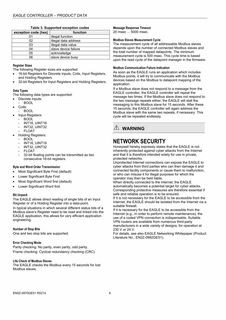
Table 3. Supported exception codes exception code (hex) function
01 illegal function 02 illegal data address 03 illegal data value 04 slave device failure 05 acknowledge 06 slave device busy
Register Sizes The following Register sizes are supported: 16-bit Registers for Discrete inputs, Coils, Input Registers,
and Holding Registers 32-bit Registers for Input Registers and Holding Registers. Data Types The following data types are supported: Discrete Inputs:
- BOOL Coils:
- BOOL Input Registers:
- BOOL - INT16, UINT16 - INT32, UINT32 - FLOAT
Holding Registers: - BOOL - INT16, UINT16 - INT32, UINT32 - FLOAT - 32-bit floating points can be transmitted as two
consecutive 16-bit registers. Byte and Word Order Transmission Most Significant Byte First (default)
Lower Significant Byte First
Most Significant Word first (default)
Lower Significant Word first Bit Unpack The EAGLE allows direct reading of single bits of an Input Register or of a Holding Register into a data-point. In typical situations in which several different status bits of a Modbus slave’s Register need to be read and linked into the EAGLE application, this allows for very efficient application engineering. Number of Stop Bits One and two stop bits are supported. Error Checking Mode Parity checking: No parity, even parity, odd parity. Frame checking: Cyclical redundancy checking (CRC). Life Check of Modbus Slaves The EAGLE checks the Modbus every 15 seconds for lost Modbus slaves.
Message Response Timeout 20 msec ... 5000 msec. Modbus Slaves Measurement Cycle The measurement cycle of all addressable Modbus slaves depends upon the number of connected Modbus slaves and the total number of mapped datapoints. The minimum measurement cycle is 500 msec. This cycle time is based upon the read cycle of the datapoint manager in the firmware. Modbus Communication Failure Indication As soon as the EAGLE runs an application which includes Modbus points, it will try to communicate with the Modbus devices based on the Modbus to datapoint mapping of the application. If a Modbus slave does not respond to a message from the EAGLE controller, the EAGLE controller will repeat the message two times. If the Modbus slave does not respond to the two message repeats either, the EAGLE will stall the messaging to this Modbus slave for 15 seconds. After these 15 seconds, the EAGLE controller will again address the Modbus slave with the same two repeats, if necessary. This cycle will be repeated endlessly.
WARNING
NETWORK SECURITY Honeywell hereby expressly states that the EAGLE is not inherently protected against cyber attacks from the Internet and that it is therefore intended solely for use in private, protected networks. Unprotected Internet connections can expose the EAGLE to cyber attacks from third parties who can then damage it and connected facility components or cause them to malfunction, or who can misuse it for illegal purposes for which the operator may then be held liable. When directly connected to the Internet, the EAGLE automatically becomes a potential target for cyber attacks. Corresponding protective measures are therefore essential if safe and reliable operation is to be ensured. If it is not necessary for the EAGLE to be accessible from the Internet, the EAGLE should be isolated from the Internet via a suitable firewall. If it is necessary for the EAGLE to be accessible from the Internet (e.g., in order to perform remote maintenance), the use of a coded VPN connection is indispensable. Suitable VPN routers are available from numerous third-party manufacturers in a wide variety of designs, for operation at 230 V or 24 V. For details, see also EAGLE Networking Whitepaper (Product Literature No.: EN2Z-0992GE51).
EAGLE CONTROLLER – PRODUCT DATA
EN0Z-0970GE51 R0214 7
CONTROLLER SPECIFICATIONS General
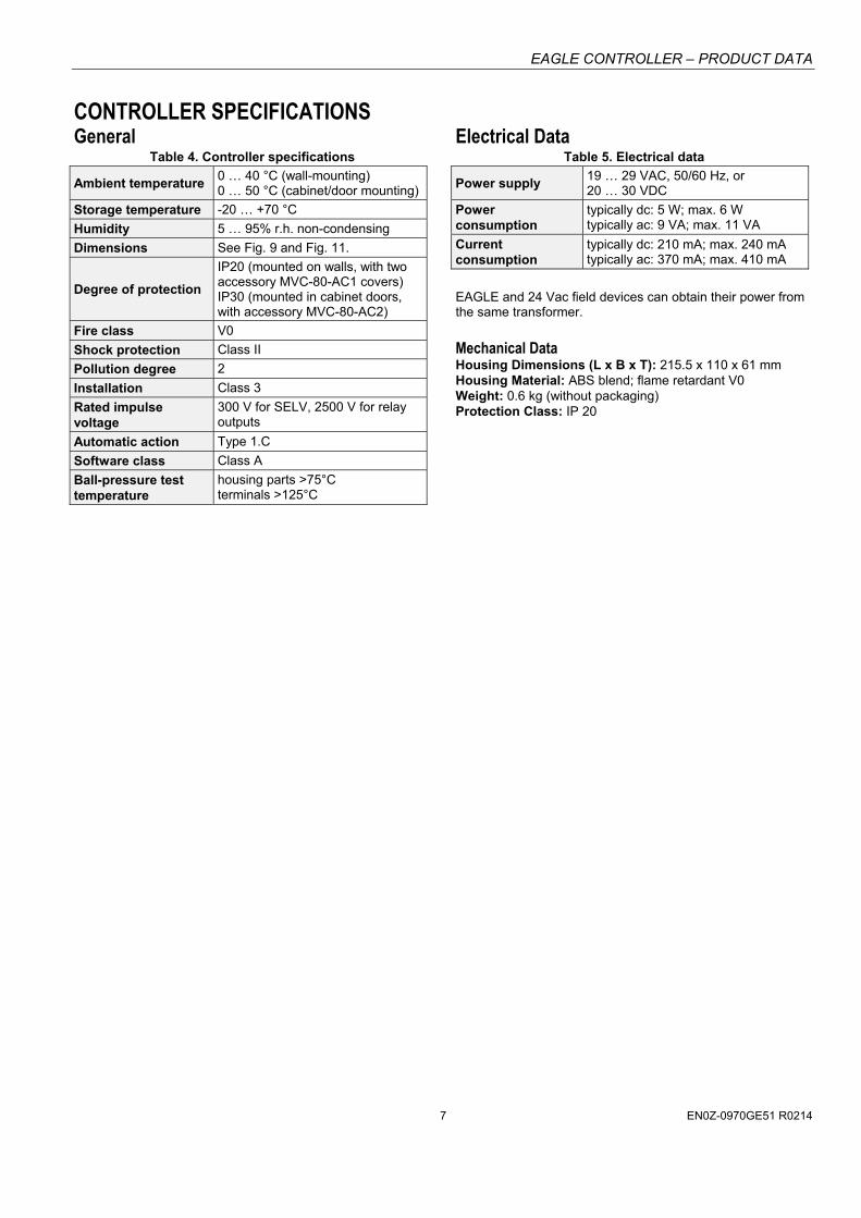
Table 4. Controller specifications
Ambient temperature 0 … 40 °C (wall-mounting) 0 … 50 °C (cabinet/door mounting)
Storage temperature -20 … +70 °C
Humidity 5 … 95% r.h. non-condensing
Dimensions See Fig. 9 and Fig. 11.
Degree of protection
IP20 (mounted on walls, with two accessory MVC-80-AC1 covers) IP30 (mounted in cabinet doors, with accessory MVC-80-AC2)
Fire class V0
Shock protection Class II
Pollution degree 2
Installation Class 3
Rated impulse voltage
300 V for SELV, 2500 V for relay outputs
Automatic action Type 1.C
Software class Class A
Ball-pressure test temperature
housing parts >75°C terminals >125°C
Electrical Data Table 5. Electrical data
Power supply 19 … 29 VAC, 50/60 Hz, or 20 … 30 VDC
Power consumption
typically dc: 5 W; max. 6 W typically ac: 9 VA; max. 11 VA
Current consumption
typically dc: 210 mA; max. 240 mA typically ac: 370 mA; max. 410 mA
EAGLE and 24 Vac field devices can obtain their power from the same transformer.
Mechanical Data Housing Dimensions (L x B x T): 215.5 x 110 x 61 mm Housing Material: ABS blend; flame retardant V0 Weight: 0.6 kg (without packaging) Protection Class: IP 20
EAGLE CONTROLLER – PRODUCT DATA
EN0Z-0970GE51 R0214 8
CPU Processor
ARM 9 32-bit processor, 450 MHz
Operating System
LINUX Memory 128 MB DDR2-RAM 1 GB Flash Memory Real-Time Clock accuracy: ± 2 minutes per year (at, typically, 25 °C) buffered typically for 72 h by gold capacitor
Standards, Approvals, etc. Device meets BTL, AMEV AS-A, EN 60730-1, EN 60730-
2-9, UL60730, and UL916. Refer to Code of Practice standards IEC 61000-5-1 and -2
for guidance. The device complies with Ethernet Protocol versions
IEEEC 802.3. The device supports BACnet IP and BACnet MS/TP
communications as per ANSI / ASHRAE 135-2010.
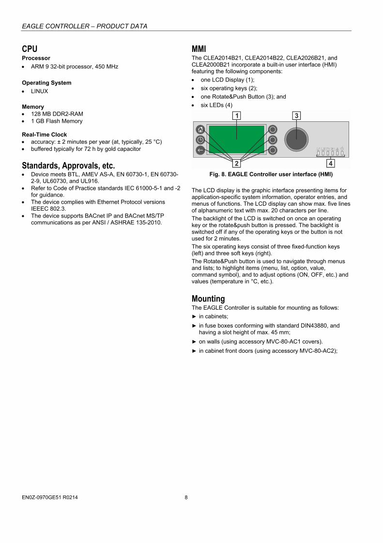
MMI The CLEA2014B21, CLEA2014B22, CLEA2026B21, and CLEA2000B21 incorporate a built-in user interface (HMI) featuring the following components:
one LCD Display (1);
six operating keys (2);
one Rotate&Push Button (3); and
six LEDs (4)
1 3
42
Fig. 8. EAGLE Controller user interface (HMI) The LCD display is the graphic interface presenting items for application-specific system information, operator entries, and menus of functions. The LCD display can show max. five lines of alphanumeric text with max. 20 characters per line. The backlight of the LCD is switched on once an operating key or the rotate&push button is pressed. The backlight is switched off if any of the operating keys or the button is not used for 2 minutes. The six operating keys consist of three fixed-function keys (left) and three soft keys (right). The Rotate&Push button is used to navigate through menus and lists; to highlight items (menu, list, option, value, command symbol), and to adjust options (ON, OFF, etc.) and values (temperature in °C, etc.).
Mounting The EAGLE Controller is suitable for mounting as follows:
in cabinets;
in fuse boxes conforming with standard DIN43880, and having a slot height of max. 45 mm;
on walls (using accessory MVC-80-AC1 covers).
in cabinet front doors (using accessory MVC-80-AC2);
EAGLE CONTROLLER – PRODUCT DATA
EN0Z-0970GE51 R0214 9
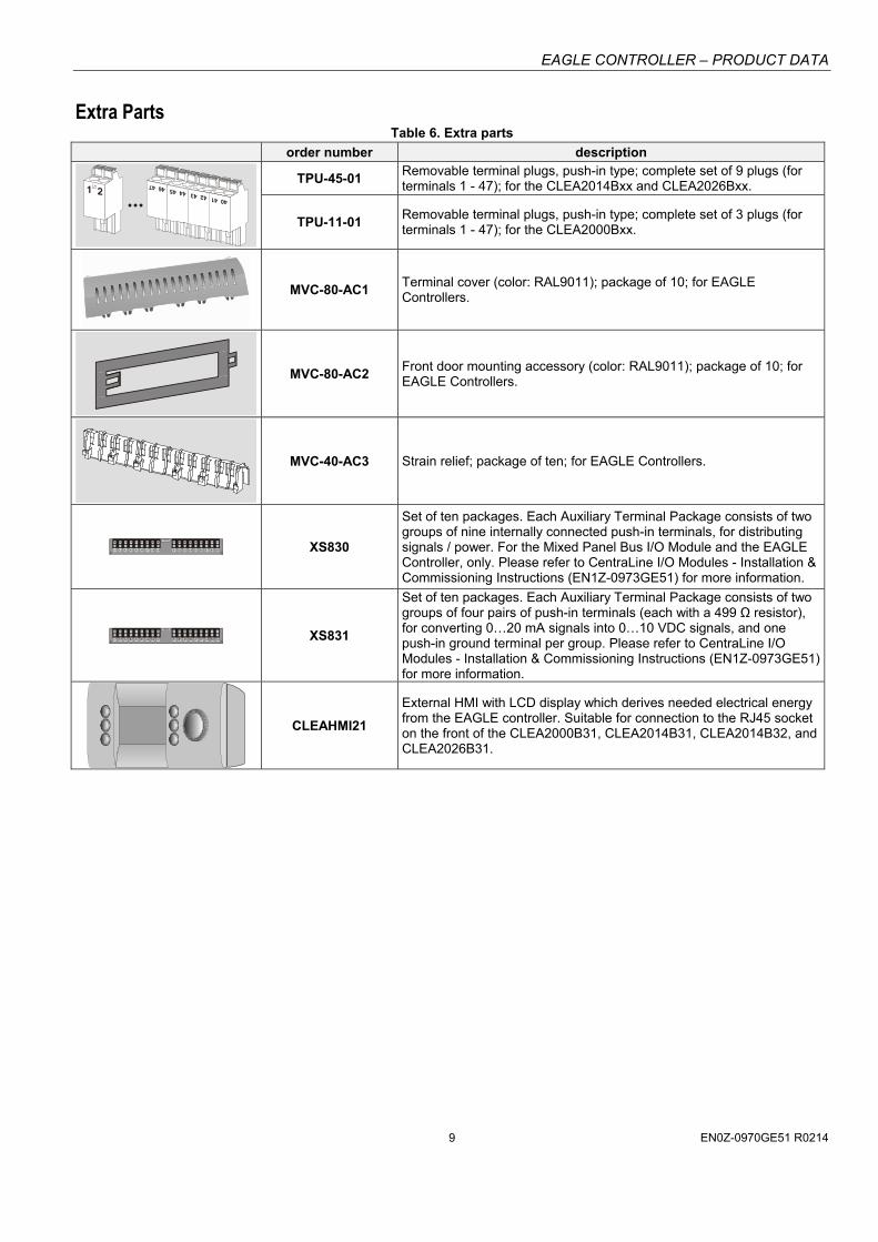
Extra Parts Table 6. Extra parts
order number description
TPU-45-01 Removable terminal plugs, push-in type; complete set of 9 plugs (for terminals 1 - 47); for the CLEA2014Bxx and CLEA2026Bxx.
TPU-11-01 Removable terminal plugs, push-in type; complete set of 3 plugs (for terminals 1 - 47); for the CLEA2000Bxx.
MVC-80-AC1 Terminal cover (color: RAL9011); package of 10; for EAGLE Controllers.
MVC-80-AC2 Front door mounting accessory (color: RAL9011); package of 10; for EAGLE Controllers.
MVC-40-AC3 Strain relief; package of ten; for EAGLE Controllers.
A1 A2 A3 A4 A5 A6 A7 A8 A9 B1 B2 B3 B4 B5 B6 B7 B8 B9 XS830
Set of ten packages. Each Auxiliary Terminal Package consists of two groups of nine internally connected push-in terminals, for distributing signals / power. For the Mixed Panel Bus I/O Module and the EAGLE Controller, only. Please refer to CentraLine I/O Modules - Installation & Commissioning Instructions (EN1Z-0973GE51) for more information.
A1 B1 A2 B2 A3 B3 A4 B4 G1 G2A5 B5 A6 B6 A7 B7 A8 B8 XS831
Set of ten packages. Each Auxiliary Terminal Package consists of two groups of four pairs of push-in terminals (each with a 499 Ω resistor), for converting 0…20 mA signals into 0…10 VDC signals, and one push-in ground terminal per group. Please refer to CentraLine I/O Modules - Installation & Commissioning Instructions (EN1Z-0973GE51) for more information.
CLEAHMI21
External HMI with LCD display which derives needed electrical energy from the EAGLE controller. Suitable for connection to the RJ45 socket on the front of the CLEA2000B31, CLEA2014B31, CLEA2014B32, and CLEA2026B31.
EAGLE CONTROLLER – PRODUCT DATA
EN0Z-0970GE51 R0214 10
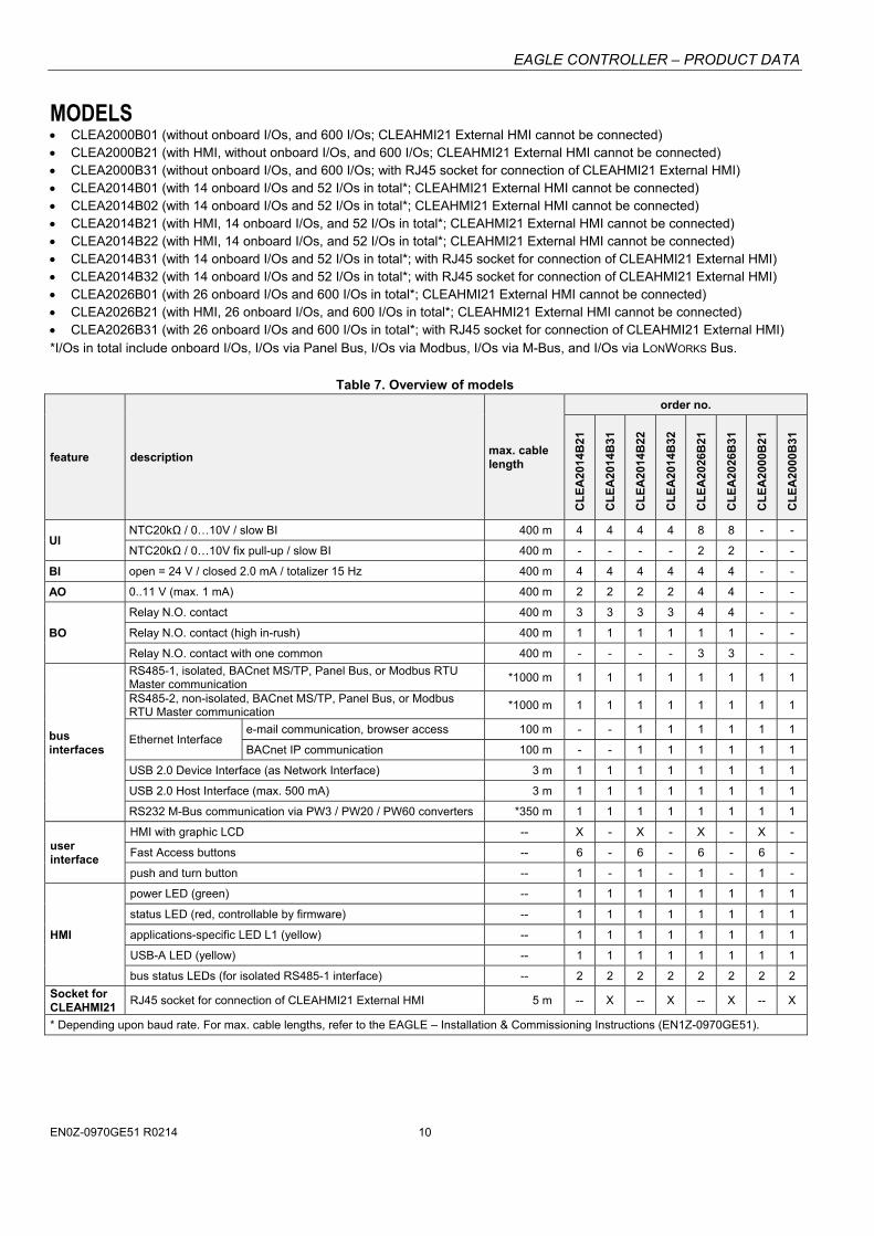
MODELS CLEA2000B01 (without onboard I/Os, and 600 I/Os; CLEAHMI21 External HMI cannot be connected) CLEA2000B21 (with HMI, without onboard I/Os, and 600 I/Os; CLEAHMI21 External HMI cannot be connected) CLEA2000B31 (without onboard I/Os, and 600 I/Os; with RJ45 socket for connection of CLEAHMI21 External HMI) CLEA2014B01 (with 14 onboard I/Os and 52 I/Os in total*; CLEAHMI21 External HMI cannot be connected) CLEA2014B02 (with 14 onboard I/Os and 52 I/Os in total*; CLEAHMI21 External HMI cannot be connected) CLEA2014B21 (with HMI, 14 onboard I/Os, and 52 I/Os in total*; CLEAHMI21 External HMI cannot be connected) CLEA2014B22 (with HMI, 14 onboard I/Os, and 52 I/Os in total*; CLEAHMI21 External HMI cannot be connected) CLEA2014B31 (with 14 onboard I/Os and 52 I/Os in total*; with RJ45 socket for connection of CLEAHMI21 External HMI) CLEA2014B32 (with 14 onboard I/Os and 52 I/Os in total*; with RJ45 socket for connection of CLEAHMI21 External HMI) CLEA2026B01 (with 26 onboard I/Os and 600 I/Os in total*; CLEAHMI21 External HMI cannot be connected) CLEA2026B21 (with HMI, 26 onboard I/Os, and 600 I/Os in total*; CLEAHMI21 External HMI cannot be connected) CLEA2026B31 (with 26 onboard I/Os and 600 I/Os in total*; with RJ45 socket for connection of CLEAHMI21 External HMI) *I/Os in total include onboard I/Os, I/Os via Panel Bus, I/Os via Modbus, I/Os via M-Bus, and I/Os via LONWORKS Bus.
Table 7. Overview of models
feature description max. cable length
order no.
CL
EA
2014
B21
CL
EA
2014
B31
CL
EA
2014
B22
CL
EA
2014
B32
CL
EA
2026
B21
CL
EA
2026
B31
CL
EA
2000
B21
CL
EA
2000
B31
UI NTC20kΩ / 0…10V / slow BI 400 m 4 4 4 4 8 8 - -
NTC20kΩ / 0…10V fix pull-up / slow BI 400 m - - - - 2 2 - -
BI open = 24 V / closed 2.0 mA / totalizer 15 Hz 400 m 4 4 4 4 4 4 - -
AO 0..11 V (max. 1 mA) 400 m 2 2 2 2 4 4 - -
BO
Relay N.O. contact 400 m 3 3 3 3 4 4 - -
Relay N.O. contact (high in-rush) 400 m 1 1 1 1 1 1 - -
Relay N.O. contact with one common 400 m - - - - 3 3 - -
bus interfaces
RS485-1, isolated, BACnet MS/TP, Panel Bus, or Modbus RTU Master communication
*1000 m 1 1 1 1 1 1 1 1
RS485-2, non-isolated, BACnet MS/TP, Panel Bus, or Modbus RTU Master communication
*1000 m 1 1 1 1 1 1 1 1
Ethernet Interface e-mail communication, browser access 100 m - - 1 1 1 1 1 1
BACnet IP communication 100 m - - 1 1 1 1 1 1
USB 2.0 Device Interface (as Network Interface) 3 m 1 1 1 1 1 1 1 1
USB 2.0 Host Interface (max. 500 mA) 3 m 1 1 1 1 1 1 1 1
RS232 M-Bus communication via PW3 / PW20 / PW60 converters *350 m 1 1 1 1 1 1 1 1
user interface
HMI with graphic LCD -- X - X - X - X -
Fast Access buttons -- 6 - 6 - 6 - 6 -
push and turn button -- 1 - 1 - 1 - 1 -
HMI
power LED (green) -- 1 1 1 1 1 1 1 1
status LED (red, controllable by firmware) -- 1 1 1 1 1 1 1 1
applications-specific LED L1 (yellow) -- 1 1 1 1 1 1 1 1
USB-A LED (yellow) -- 1 1 1 1 1 1 1 1
bus status LEDs (for isolated RS485-1 interface) -- 2 2 2 2 2 2 2 2
Socket for CLEAHMI21
RJ45 socket for connection of CLEAHMI21 External HMI 5 m -- X -- X -- X -- X
* Depending upon baud rate. For max. cable lengths, refer to the EAGLE – Installation & Commissioning Instructions (EN1Z-0970GE51).
EAGLE CONTROLLER – PRODUCT DATA
EN0Z-0970GE51 R0214 11
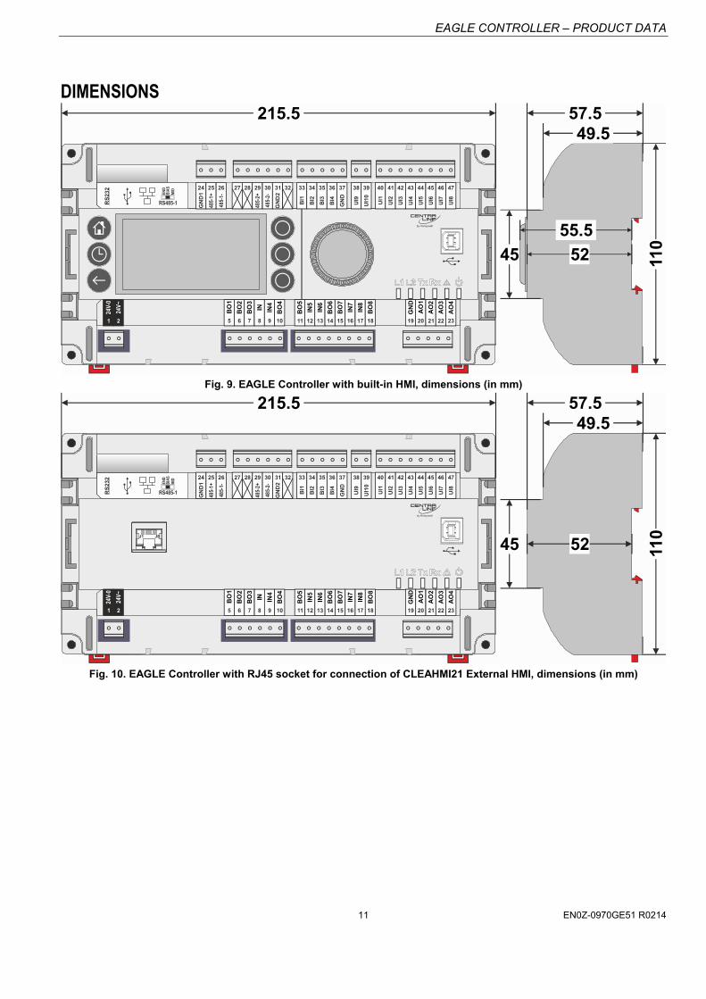
DIMENSIONS
110
215.5
45
BI1
BI2
BI3
BI4
GN
D
UI1
UI2
UI3
UI4
UI5
UI6
UI7
24 25 26 27 28 29 30 31 32 33 34 35 36 37 38 39 40 41 42 43 44 45 46
UI8
47
BO
1
BO
2
BO
3
IN IN4
BO
4
BO
5
IN5
IN6
BO
6
BO
7
IN7
IN8
BO
8
GN
D
AO
1
AO
2
AO
3
5 6 7 8 9 10 11 12 13 14 15 16 17 18 19 20 21 22
24V-
0
24V~
1
AO
4
23
GN
D1
485-
1+
485-
1-
GN
D2
485-
2+
485-
2-
UI9
UI1
0
2
52
49.557.5
55.5
RS
232
RS485-1
END
BIA
SM
ID
Fig. 9. EAGLE Controller with built-in HMI, dimensions (in mm)
110
215.5
5245
BI1
BI2
BI3
BI4
GN
D
UI1
UI2
UI3
UI4
UI5
UI6
UI7
24 25 26 27 28 29 30 31 32 33 34 35 36 37 38 39 40 41 42 43 44 45 46
UI8
47
BO
1
BO
2
BO
3
IN IN4
BO
4
BO
5
IN5
IN6
BO
6
BO
7
IN7
IN8
BO
8
GN
D
AO
1
AO
2
AO
3
5 6 7 8 9 10 11 12 13 14 15 16 17 18 19 20 21 22
24V-
0
24V~
1
AO
4
23
GN
D1
485-
1+
485-
1-
GN
D2
485-
2+
485-
2-
UI9
UI1
0
2
49.557.5
J1 J8
RS
232
RS485-1
END
BIA
SM
ID
Fig. 10. EAGLE Controller with RJ45 socket for connection of CLEAHMI21 External HMI, dimensions (in mm)
EAGLE CONTROLLER – PRODUCT DATA
Manufactured for and on behalf of the Environmental and Combustion Controls Division of Honeywell Technologies Sàrl, Rolle, Z.A. La Pièce 16, Switzerland by its Authorized Representative:
CentraLine Honeywell GmbH Böblinger Strasse 17 71101 Schönaich, Germany phone: +49 7031 637 845 fax: +49 7031 637 740 [email protected] www.centraline.com
Printed in Germany. Subject to change without notice. EN0Z-0970GE51 R0214
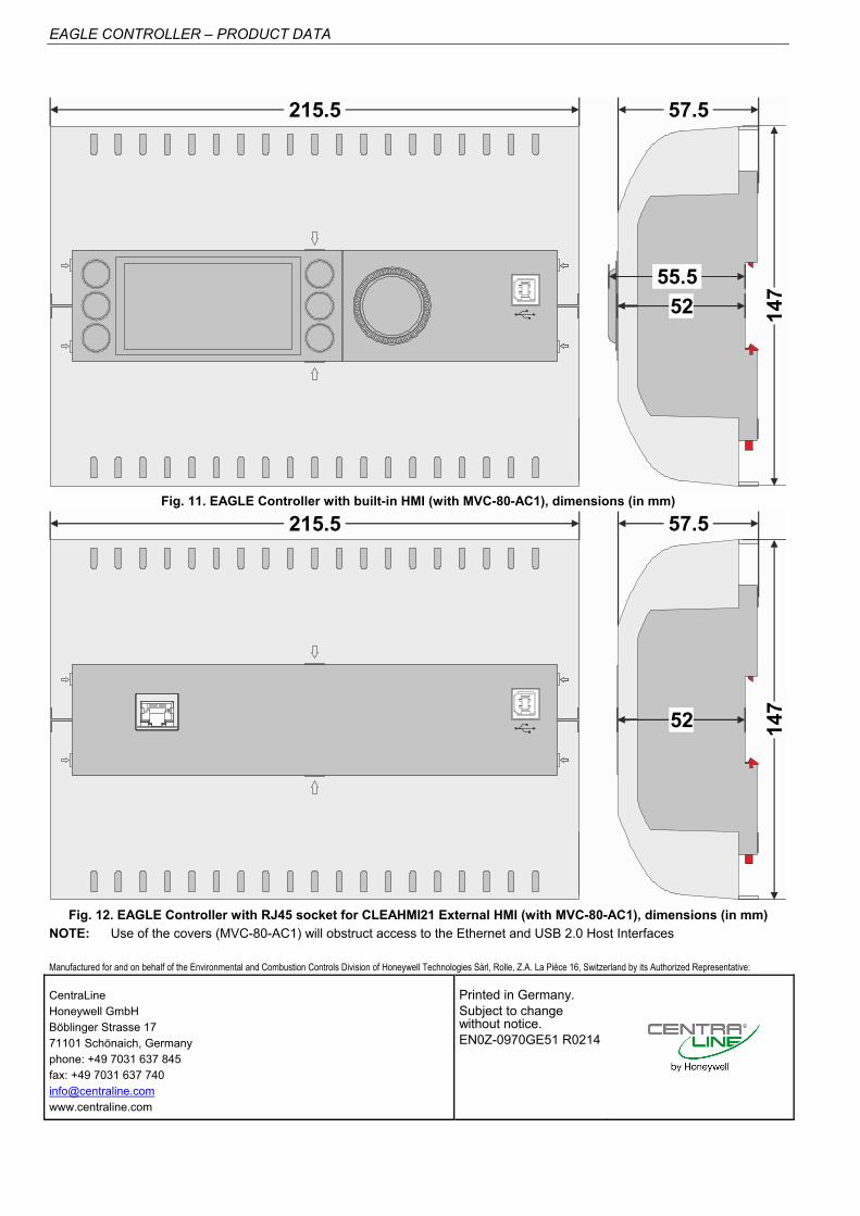
147
57.5215.5
52
55.5
Fig. 11. EAGLE Controller with built-in HMI (with MVC-80-AC1), dimensions (in mm)
147
57.5215.5
J1 J8
52
Fig. 12. EAGLE Controller with RJ45 socket for CLEAHMI21 External HMI (with MVC-80-AC1), dimensions (in mm)
NOTE: Use of the covers (MVC-80-AC1) will obstruct access to the Ethernet and USB 2.0 Host Interfaces