Embed Size (px)
Citation preview
www.mrd.com.au
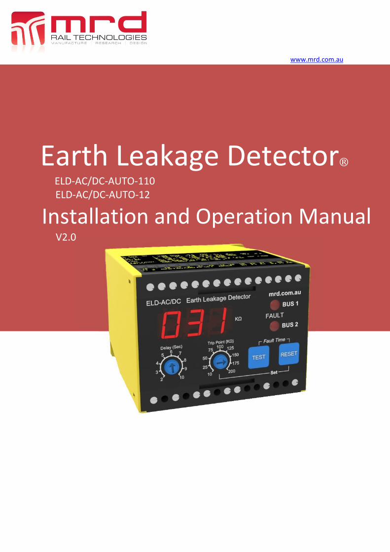
Earth Leakage Detector®
ELD-AC/DC-AUTO-110 ELD-AC/DC-AUTO-12
Installation and Operation Manual V2.0

Earth Leakage Detector (ELD) User Manual The software described in this manual is furnished under a license agreement and may be used only in accordance with the terms of that agreement.
Copyright Notice © 2012 MRD Rail Technologies Pty Ltd. All rights reserved.
Trademarks
The MRD logo is registered trademark of MRD Rail Technologies Pty Ltd.
All other trademarks or registered marks in this manual belong to their respective holders.
Disclaimer Information in this document is subject to change without notice and does not represent a commitment on the part of MRD Rail Technologies Pty Ltd.
MRD provides this document as is, without warranty of any kind, expressed or implied, including, but not limited to, its particular purpose. MRD reserves the right to make improvements and/or changes to this manual, or to the products and/or the programs described in this manual, at any time.
Information provided in this manual is intended to be accurate and reliable. However, MRD assumes no responsibility for its use, or for any infringements on the rights of third parties that may result from its use.
This manual, and the product it relates to, might include unintentional technical or typographical errors. Changes are periodically made to the information herein to correct such errors, and these changes are incorporated into new edition of the publication.
Technical Support Contact Information Tel: +61 7 3821 5151
Fax: +61 7 3821 5152
Email: [email protected]
Contents 1. Introduction ........................................................................................................................................ 1
2. General Description ............................................................................................................................ 1
3. Product Features ................................................................................................................................. 1
4. Wiring Diagram ................................................................................................................................... 2
5. Connectors .......................................................................................................................................... 5
6. Installation .......................................................................................................................................... 6
7. Functions ............................................................................................................................................. 7
8. Operation instructions for monitoring AC busbars ............................................................................. 8
9. Operation instructions for monitoring DC busbars ............................................................................ 9
10. Remote Monitoring ......................................................................................................................... 10
11. Technical Data ................................................................................................................................. 15
12. Ordering Information ...................................................................................................................... 15
Table of Contents

ELD™ User Manual Version 2.1 Page 1 of 14
Despite all the safety built into our electrical rail systems, failures can and do occur. MRD’s Earth Leakage Detectors (ELD’s) significantly reduce the likelihood of failure or accidents due to leakage faults.
• Panel Layout
Leakage from battery
The interlocking circuits in railway signalling are often supplied from a battery in which neither of the poles are
connected to earth. In the event of a single fault there is no danger, however, two or more faults occurring at the
same time could create a dangerous situation. Therefore, it is vitally important to supervise the battery supply
continuously to prevent this from happening.
Leakage from cables, lamp circuits, etc. Cables which run in parallel with AC electrified railways are subjected to induced voltages. If an earth leakage
occurs in the cable, these voltages can disturb devices which are connected to both cables. When earth faults
occur in both the supply and return wires yet another hazardous condition is created.
These faults are detected and indicated reliably with MRD’s Earth Leakage Detector.
• AC Supply or DC Supply versions.
• Auto detects & monitors AC or DC busbar voltages: 8 – 150V DC, 0 – 650V AC.
• Continuously displays fault level in KΩ – Remove leakages before critical level reached.
• Displays fault time – Helps track cause of fault.
• Adjustable sensitivity: 10 KΩ – 200 KΩ.
• Adjustable delay: 2 sec – 10 sec.
• Self-Test and Reset buttons.
• Power on and trip indications.
• Fail-safe or Non-Fail-safe trip contact operation.
• Compact Size - Din rail or Panel mounting.
• Remote reset.
• Remote interrogation via RS-485 Communications Link.
1. Introduction
2. General Description
3. Product Features

ELD™ User Manual Version 2.1 Page 2 of 14
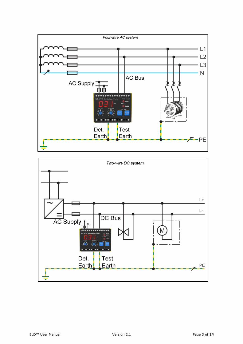
NOTE:
The use of fuses on the ELD Supply and ELD Busbar is recommended for electrical safety for signalling circuits
(1A or 2A fuse is recommended).
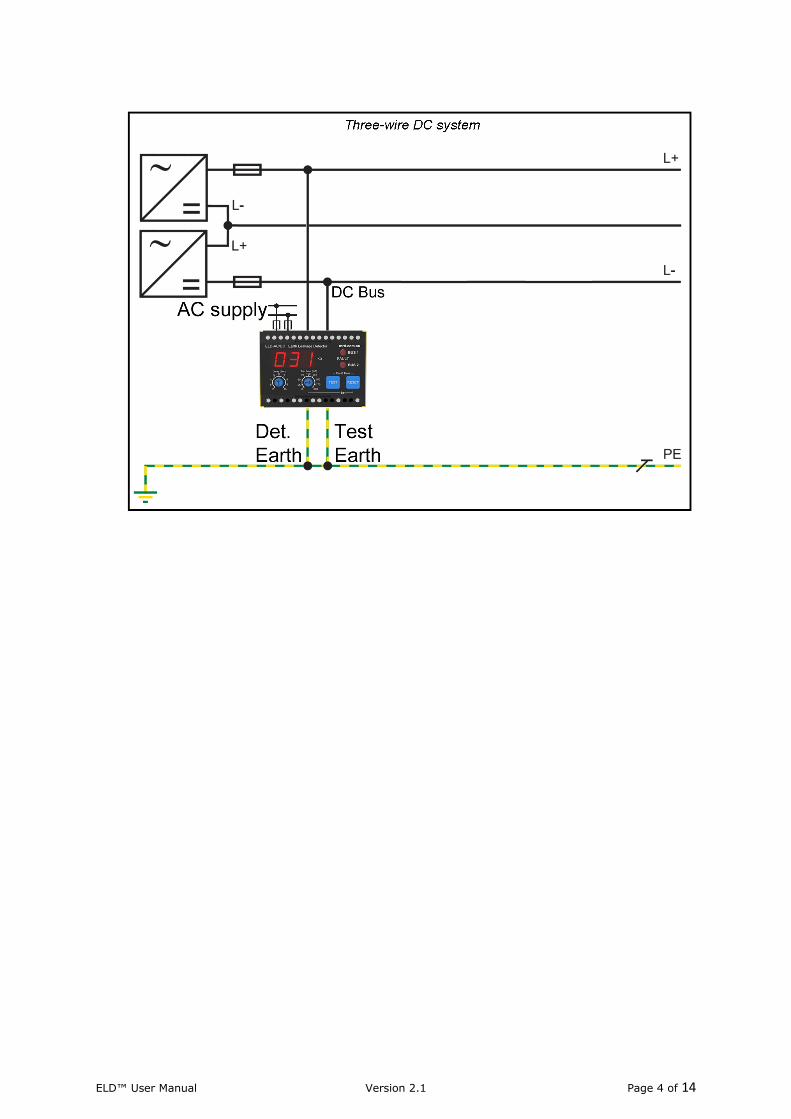
4. Wiring Diagram
ELD™ User Manual Version 2.1 Page 3 of 14
ELD™ User Manual Version 2.1 Page 4 of 14
ELD™ User Manual Version 2.1 Page 5 of 14
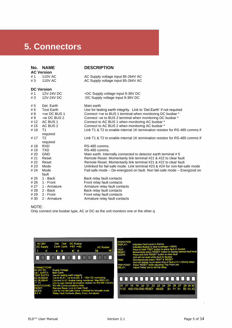
No. NAME DESCRIPTION AC Version # 1 110V AC AC Supply voltage input 85-264V AC # 3 110V AC AC Supply voltage input 85-264V AC
DC Version # 1 12V-24V DC +DC Supply voltage input 9-36V DC # 3 12V-24V DC -DC Supply voltage input 9-36V DC # 5 Det. Earth Main earth # 6 Test Earth Use for testing earth integrity. Link to ‘Det.Earth’ if not required # 8 +ve DC BUS 1 Connect +ve to BUS 1 terminal when monitoring DC busbar * # 9 -ve DC BUS 2 Connect -ve to BUS 2 terminal when monitoring DC busbar * # 12 AC BUS 1 Connect to AC BUS 1 when monitoring AC busbar * # 15 AC BUS 2 Connect to AC BUS 2 when monitoring AC busbar * # 16 T1 Link T1 & T2 to enable internal 1K termination resistor for RS-485 comms if
required # 17 T2 Link T1 & T2 to enable internal 1K termination resistor for RS-485 comms if
required # 18 RXD RS-485 comms. # 19 TXD RS-485 comms. # 20 GND Main earth. Internally connected to detector earth terminal # 5 # 21 Reset Remote Reset. Momentarily link terminal #21 & #22 to clear fault # 22 Reset Remote Reset. Momentarily link terminal #21 & #22 to clear fault # 23 Mode Unlinked for fail-safe mode. Link terminal #23 & #24 for non-fail-safe mode # 24 Mode Fail-safe mode – De-energized on fault. Non fail-safe mode – Energized on
fault # 25 1 - Back Back relay fault contacts # 26 1 - Front Front relay fault contacts # 27 1 - Armature Armature relay fault contacts # 28 2 - Back Back relay fault contacts # 29 2 - Front Front relay fault contacts # 30 2 - Armature Armature relay fault contacts
NOTE: Only connect one busbar type, AC or DC as the unit monitors one or the other.q
5. Connectors
ELD™ User Manual Version 2.1 Page 6 of 14
1. Mount detector on a din rail using the rail clip on base of unit. Alternatively the unit can be panel mounted using the two base holes as a mounting point. An optional Q-Style panel mount bracket is also available. 2. Make connections as shown in wiring diagrams. If monitoring AC busbar, wire as per AC diagram. If monitoring DC busbar, wire as per DC diagram. Note 1: Only monitors one busbar, AC or DC. Do not connect both. Note 2: Do not over loosen terminal screws as this may cause terminal holders to displace from terminal
block. 3. Test Earth / Detector Earth Connections. Our recommendation is to use a separate earth stake for test earth and detector earth.
Why? The separate test earth proves the detector earth connection when performing the self-test function (pressing the test button). This places an internal 10 KΩ resistor between the busbar and the test earth.
The leakage return path is between the test earth stake and the detector earth stake via a body of earth. If there is a problem with the detector earth connection this will be indicated by self-test function failure. The self-test function should be performed routinely as specified by signaling authority.
If the test earth and detector earth are connected together the unit will still function correctly, although pressing the self-test button will not check the validity of the detector earth. In fact the self-test will still work even if no connection to the main earth is made as long as a link is placed between the test and detector earths.
This defeats the purpose of the self-test function.
4. Adjust ‘Trip Point’ and ‘Trip Delay’ pots on the front panel to desired thresholds.
5. The unit is now connected for operation. Please follow operation instructions to ensure correct use of unit.
6. Installation
ELD™ User Manual Version 2.1 Page 7 of 14
Display: Indicates leakage level in KΩ. ‘---‘: Indicates busbar is clear & that the current leakage level is above 500 KΩ. Test: Press & hold test button to place 10 KΩ fault on busbar.
Once the set delay & trip thresholds have been reached the unit will trip and latch a fault. This is indicated by the illumination of bus fault LED’s. Displayed leakage level should also reach approximately 10 KΩ while performing test. Existing leakages will affect displayed leakage value when performing this test. TEST NOTES: Self-test will only operate correctly if low resistance connection between ‘Test Earth’ & ‘Detector Earth’ terminals exist. This connection is usually made through test stakes in the ground. Failure of unit to trip when performing self-test indicates a problem with the test earth or detector earth connections or an existing fault. Link the ‘Test Earth’ & ‘Detector Earth’ if not using test stakes or to prove unit. Pressing ‘Test’ for more than ten seconds at a time will cause unit to remove Test resistor from busbar to prevent over heating or damage to unit.
Reset: Momentarily press ‘RESET’ to display stored fault level. Press & hold reset in to clear fault. Unit will not reset while fault remains on busbar. If power is interrupted to unit, latched faults will be restored as stored in memory,
however, fault time will be lost & displayed as ‘00.0’. Fault Time: Simultaneously press ‘TEST’ & ‘RESET’. Unit will display count down time of fault in 0.1 (10 min) steps. Display will show ‘00.0’ until first ten minutes has lapsed. Eg.1. ‘00.1’ indicates fault occurred at minus 10 minutes. Eg.2. ‘11.1’ indicates fault occurred at minus 11 hours and ten minutes. If power is interrupted to unit, latched faults will be restored as stored in memory,
however, fault time will be lost & displayed as ‘00.0’. Trip Point: Press ‘RESET’ while adjusting ‘Trip Point’ pot. Display will show trip point setting. Trip point will not be displayed if there is a latched fault on busbar. Delay: Adjust ‘Delay’ pot to set trip delay.
7. Functions
ELD™ User Manual Version 2.1 Page 8 of 14
Step 1 – Initial Power Up When the unit is initially powered up it detects the busbar voltage being monitored. The unit will display ‘CAL’ during this procedure. Following detection of the AC busbar the unit will display ‘AC’ for 2 seconds.
NOTE: It is not necessary for the AC busbar being monitored to to be powered up for the AC busbar to be detected. It is only necessary for the unit to have a connection through the secondary winding of the AC busbar supply transformer being monitored. This is because the unit injects a DC voltage into one leg of the AC busbar and looks for a return voltage on the other leg. If the AC busbar is not connected the unit will trip indicating a fault condition which can only be reset once this connection is present. A power down condition on the AC busbar will not cause the unit to trip as long as this connection is made.
Step 2 – Trip Point & Trip Delay Adjust Adjust ‘Trip Point’ and ‘Trip Delay’ pots on the front panel to desired thresholds. For fine trip point adjustment, press and hold the ‘Reset’ button while adjusting the ‘Trip Point’ pot. The Display will show the set “Trip Point’ while the ‘Reset’ button is pressed unless there is a fault latched. If there is fault latched the display will show the level at which the trip occurred.
Step 3 – Display Interpretation The unit displays the current leakage level on the 3 digit 7-segment display in KΩ. When there is no leakage or the leakage is above 500 KΩ the unit displays ‘- - -‘. Display other than ‘- - -’ indicates an existing earth leakage.
Step 4 – Self Test The unit has a built in test facility which momentarily connects a 10 KΩ resistor between the busbar and test earth. Press & hold the ‘TEST” button to place a 10 KΩ fault on the busbar. Once the set delay and trip thresholds have been reached the unit will trip and latch the fault. This is indicated by the illumination of BUS1 and BUS2 fault LED’s and the trip relay contacts changing state. Displayed leakage level should also reach approximately 10 KΩ while performing test. Press and hold ‘Reset’ button to clear fault.
NOTE: Self-test function will only work when there is no existing latched fault. For this feature to operate correctly, a low resistance connection between the ‘Test Earth’ and ‘Detector Earth’ terminals must exist. This is usually made via test stakes in ground. Failure of unit to trip when performing self-test indicates a likely problem with test earth or detector earth connections or an already latched fault. Link the ‘Test Earth’ & ‘Detector Earth’ if not using test stakes or to prove unit. Pressing ‘Test’ for more than ten seconds at a time will cause unit to remove test resistor from busbar to prevent over heating or damage to unit.
Step 5 – Fault Reset When a leakage occurs that exceeds the set trip point and delay time, a fault is latched. Both fault LED’s illuminate and the trip relay contacts change state. Momentarily pressing the reset button will display the recorded trip level for 1 second without resetting the fault. Press and hold the reset button to reset a latched fault. Resetting the fault will cause both fault LED’s to extinguish and the trip relay contacts to change state.
NOTE: A latched fault can only be reset once the fault has been removed from the busbar.
monitoring AC busbars
8. Operation instructions for
ELD™ User Manual Version 2.1 Page 9 of 14
Step 1 – Initial Power Up When the unit is initially powered up it detects the busbar voltage being monitored. The unit will display ‘CAL’ during this procedure. Following detection of the DC busbar the unit will display the detected DC voltage for 2 seconds followed by ‘DC’ for 2 seconds.
NOTE: If the DC busbar is not present the unit will trip indicating a fault condition. This fault condition will automatically reset once the DC busbar is present.
Step 2 – Trip Point & Trip Delay Adjust Adjust ‘Trip Point’ and ‘Trip Delay’ pots on the front panel to desired thresholds. For fine trip point adjustment, press and hold the ‘Reset’ button while adjusting the ‘Trip Point’ pot. The Display will show the set “Trip Point’ while the ‘Reset’ button is pressed unless there is a fault latched. If there is fault latched the display will show the level at which the trip occurred.
Step 3 – Display Interpretation The unit displays the current leakage level on the 3 digit 7-segment display in KΩ. When there is no leakage or the leakage is above 500 KΩ the unit displays ‘- - -‘. Display other than ‘- - -’ indicates an existing earth leakage. The BUS 1 Fault LED indicates a latched fault on BUS 1 when continually illuminated. The BUS 2 Fault LED indicates a latched fault on BUS 2 when continually illuminated. Distinguished LED’s indicate the Busbar is clear.
Step 4 – Self Test The unit has a built in test facility which momentarily connects a 10 KΩ resistor between the busbar and test earth. Press & hold the ‘TEST” button to place a 10 KΩ fault on the busbar. Once the set delay and trip thresholds have been reached the unit will trip and latch the fault. This is indicated by the illumination of BUS1 or BUS2 fault LED’s and the trip relay contacts changing state. Displayed leakage level should also reach approximately 10 KΩ while performing test. Press and hold ‘Reset’ button to clear fault. Repeat this process for the alternate DC busbar.
NOTE: Self-test function will only work when there is no existing latched fault.
For this feature to operate correctly, a low resistance connection between the ‘Test Earth’ and ‘Detector Earth’ terminals must exist. This is usually made via test stakes in ground. Failure of unit to trip when performing self-test indicates a likely problem with test earth or detector earth connections or an already latched fault. Link the ‘Test Earth’ & ‘Detector Earth’ if not using test stakes or to prove unit. Pressing ‘Test’ for more than ten seconds at a time will cause unit to remove test resistor from busbar to prevent over heating or damage to unit.
Step 5 – Fault Reset When a leakage occurs that exceeds the set trip point and delay time, a fault is latched. BUS 1 and/or BUS 2 LED’s illuminate indicating which busbar the fault is on and the trip relay contacts change state. Momentarily pressing the reset button will display the recorded trip level for 1 second without resetting the fault. Press and hold the reset button to reset a latched fault. Resetting the fault will cause the Busbar fault LED’s to extinguish and the trip relay contacts to change state.
NOTE: A latched fault can only be reset once the fault has been removed from the busbar.
9. Operation instructions for
monitoring DC busbars
ELD™ User Manual Version 2.1 Page 10 of 14
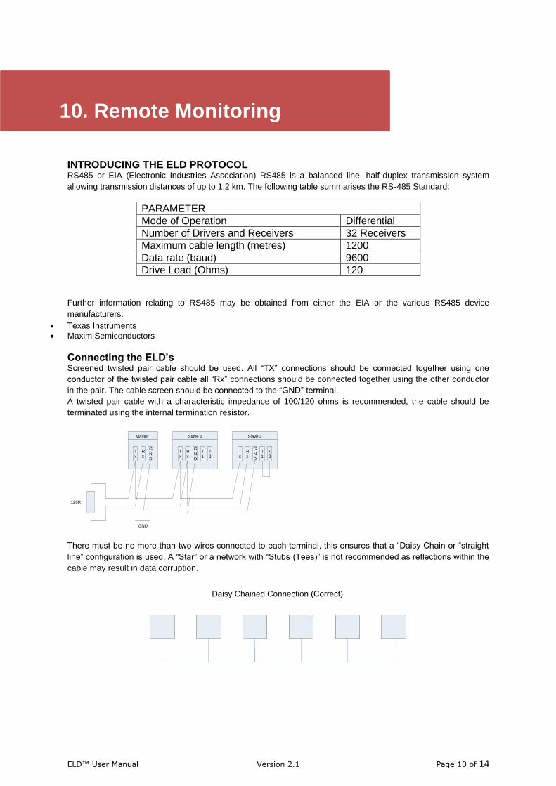
INTRODUCING THE ELD PROTOCOL RS485 or EIA (Electronic Industries Association) RS485 is a balanced line, half-duplex transmission system
allowing transmission distances of up to 1.2 km. The following table summarises the RS-485 Standard:
PARAMETER
Mode of Operation Differential
Number of Drivers and Receivers 32 Receivers
Maximum cable length (metres) 1200
Data rate (baud) 9600
Drive Load (Ohms) 120
Further information relating to RS485 may be obtained from either the EIA or the various RS485 device
manufacturers:
• Texas Instruments
• Maxim Semiconductors
Connecting the ELD’s Screened twisted pair cable should be used. All “TX” connections should be connected together using one
conductor of the twisted pair cable all “Rx” connections should be connected together using the other conductor
in the pair. The cable screen should be connected to the “GND” terminal.
A twisted pair cable with a characteristic impedance of 100/120 ohms is recommended, the cable should be
terminated using the internal termination resistor.
Slave 2
T
x
R
x
G
N
D
Master
T
x
R
x
G
N
D
T
1
T
2
Slave 1
T
x
R
x
G
N
D
T
1
T
2
120R
GND
There must be no more than two wires connected to each terminal, this ensures that a “Daisy Chain or “straight
line” configuration is used. A “Star” or a network with “Stubs (Tees)” is not recommended as reflections within the
cable may result in data corruption.
Daisy Chained Connection (Correct)
10. Remote Monitoring
ELD™ User Manual Version 2.1 Page 11 of 14
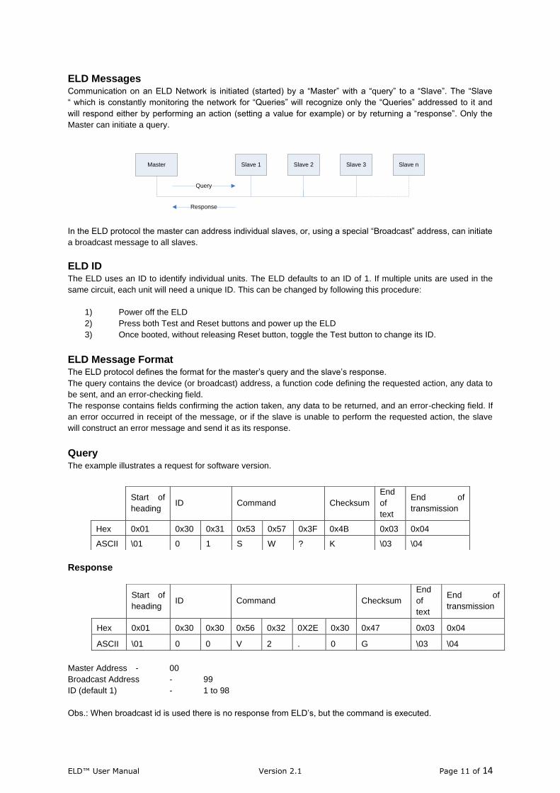
ELD Messages
Communication on an ELD Network is initiated (started) by a “Master” with a “query” to a “Slave”. The “Slave
“ which is constantly monitoring the network for “Queries” will recognize only the “Queries” addressed to it and
will respond either by performing an action (setting a value for example) or by returning a “response”. Only the
Master can initiate a query.
Master Slave 1 Slave 2 Slave 3 Slave n
Query
Response
In the ELD protocol the master can address individual slaves, or, using a special “Broadcast” address, can initiate
a broadcast message to all slaves.
ELD ID The ELD uses an ID to identify individual units. The ELD defaults to an ID of 1. If multiple units are used in the
same circuit, each unit will need a unique ID. This can be changed by following this procedure:
1) Power off the ELD
2) Press both Test and Reset buttons and power up the ELD
3) Once booted, without releasing Reset button, toggle the Test button to change its ID.
ELD Message Format The ELD protocol defines the format for the master’s query and the slave’s response.
The query contains the device (or broadcast) address, a function code defining the requested action, any data to
be sent, and an error-checking field.
The response contains fields confirming the action taken, any data to be returned, and an error-checking field. If
an error occurred in receipt of the message, or if the slave is unable to perform the requested action, the slave
will construct an error message and send it as its response.
Query The example illustrates a request for software version.
Response
Master Address - 00
Broadcast Address - 99
ID (default 1) - 1 to 98
Obs.: When broadcast id is used there is no response from ELD’s, but the command is executed.
Start of
heading ID Command Checksum
End
of
text
End of
transmission
Hex 0x01 0x30 0x31 0x53 0x57 0x3F 0x4B 0x03 0x04
ASCII \01 0 1 S W ? K \03 \04
Start of
heading ID Command Checksum
End
of
text
End of
transmission
Hex 0x01 0x30 0x30 0x56 0x32 0X2E 0x30 0x47 0x03 0x04
ASCII \01 0 0 V 2 . 0 G \03 \04
ELD™ User Manual Version 2.1 Page 12 of 14
Checksum
The ELD protocol uses an error checking process, the checksum sums up all the values from Start of heading to the end of command then the lower byte is sent, calculated and compared to the command received. Example: Software version command 0x01 + 0x30 + 0x30 + 0x56 + 0x32 + 0x2E + 0x30 = 0x147 0x147 = 00000001 01000111 High byte = 00000001 = 0x01 Lower byte = 01000111 = 0x47
ELD Commands
ID query: Command – D Response – Actual ID number This command sends back the ID number.
Edit ID: Command – EDID + “New ID” (Note: there is a space character between the command and the new ID) Response – ACK (\06) This command changes the default ID (1) number for a new ID. Example: EDID 2 - Set the ID number to 2.
Trip Point: Command – TP Response – 10 to 100 (Kohm) This command sends back the trip point level.
Bus Mode: Command – BM Response – 0 or 1 This command sends back the ELD operation mode AC (1) or DC (0).
Bus Leakage Status: Command – BL Response – 0, 1 or 2 This command sends back in which bus is the current fault. AC Mode: 0 - No Fault or 1 – Fault DC Mode: 0 – No Fault, 1 – Bus1 Fault, 2 – Bus2 Fault
Time Delay: Command – TD Response – 2 to 10 (seconds) This command sends back the time delay level.
DC Fault Time Bus1: Command – DCFT1 Response – (minutes) This command sends back the value in minutes when the fault occurred on Bus1. If the unit has been powered down this value becomes 0 (not recorded).
DC Fault Time Bus2:
Command – DCFT2
ELD™ User Manual Version 2.1 Page 13 of 14
Response – (minutes) This command sends back the value in minutes when the fault occurred on Bus2. If the unit has been powered down this value becomes 0 (not recorded).
AC Fault Time:
Command – ACFL Response – (minutes) This command sends back the value in minutes when the fault occurred on AC-Bus. If the unit has been powered down this value becomes 0 (not recorded).
DC Fault Level Bus1:
Command – DCFL1 Response – 0 to 200(Kohm) This command sends back the value of the fault level occurred on Bus1. If 201 there is no fault.
DC Fault Level Bus2:
Command – DCFL2 Response – 0 to 200(Kohm) This command sends back the value of the fault level occurred on Bus2. If 201 there is no fault.
AC Fault Level:
Command – ACFL Response – 0 to 200(Kohm) This command sends back the value of the fault level occurred on AC-Bus. If 201 there is no fault.
DC Voltage:
Command – V Response – (volts) This command sends back the value in volts of the DC Bus (0 when in AC Mode).
Resistor Leakage:
Command – RLE Response – 0 to 500(Kohm) This command sends back the value of the actual resistor leakage. If 1000 it is open circuit.
Self-test Leakage:
Command – TEST Response – ACK (\06) This command sets a 10Kohm resistor between a bus and GND. When in DC mode the resistor cycle between Bus 1 and 2.
Reset Trip Fault:
Command – RSTF Response – ACK (\06) This command resets the trip fault recorded in the EEPROM.
Reset Hardware:
Command – RESET
ELD™ User Manual Version 2.1 Page 14 of 14
Response – ACK (\06) This command resets the ELD hardware.
Software Version:
Command – SW? Response – current software version This command sends back the software version.
ELD™ User Manual Version 2.1 Page 15 of 14
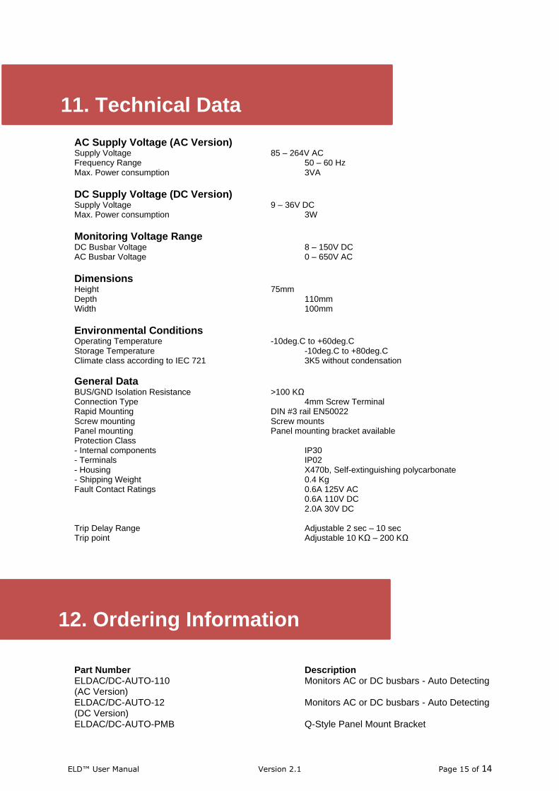
AC Supply Voltage (AC Version) Supply Voltage 85 – 264V AC Frequency Range 50 – 60 Hz Max. Power consumption 3VA
DC Supply Voltage (DC Version) Supply Voltage 9 – 36V DC Max. Power consumption 3W
Monitoring Voltage Range DC Busbar Voltage 8 – 150V DC AC Busbar Voltage 0 – 650V AC
Dimensions Height 75mm Depth 110mm Width 100mm
Environmental Conditions Operating Temperature -10deg.C to +60deg.C Storage Temperature -10deg.C to +80deg.C Climate class according to IEC 721 3K5 without condensation
General Data BUS/GND Isolation Resistance >100 KΩ Connection Type 4mm Screw Terminal Rapid Mounting DIN #3 rail EN50022 Screw mounting Screw mounts Panel mounting Panel mounting bracket available Protection Class - Internal components IP30 - Terminals IP02 - Housing X470b, Self-extinguishing polycarbonate - Shipping Weight 0.4 Kg Fault Contact Ratings 0.6A 125V AC 0.6A 110V DC 2.0A 30V DC Trip Delay Range Adjustable 2 sec – 10 sec Trip point Adjustable 10 KΩ – 200 KΩ
Part Number Description ELDAC/DC-AUTO-110 Monitors AC or DC busbars - Auto Detecting (AC Version) ELDAC/DC-AUTO-12 Monitors AC or DC busbars - Auto Detecting (DC Version) ELDAC/DC-AUTO-PMB Q-Style Panel Mount Bracket
11. Technical Data
12. Ordering Information